CN111795709A - Encoder, motor and robot - Google Patents
Encoder, motor and robot Download PDFInfo
- Publication number
- CN111795709A CN111795709A CN202010265653.8A CN202010265653A CN111795709A CN 111795709 A CN111795709 A CN 111795709A CN 202010265653 A CN202010265653 A CN 202010265653A CN 111795709 A CN111795709 A CN 111795709A
- Authority
- CN
- China
- Prior art keywords
- gear
- axis
- shaft
- encoder
- magnet
- Prior art date
- Legal status (The legal status is an assumption and is not a legal conclusion. Google has not performed a legal analysis and makes no representation as to the accuracy of the status listed.)
- Pending
Links
- 239000000758 substrate Substances 0.000 claims description 43
- 238000001514 detection method Methods 0.000 claims description 40
- 230000002093 peripheral effect Effects 0.000 description 15
- 230000003287 optical effect Effects 0.000 description 13
- 238000010586 diagram Methods 0.000 description 11
- 239000012636 effector Substances 0.000 description 6
- 238000000034 method Methods 0.000 description 5
- 238000012986 modification Methods 0.000 description 4
- 230000004048 modification Effects 0.000 description 4
- 238000009434 installation Methods 0.000 description 3
- 125000006850 spacer group Chemical group 0.000 description 3
- 238000001179 sorption measurement Methods 0.000 description 2
- 238000005299 abrasion Methods 0.000 description 1
- 238000012790 confirmation Methods 0.000 description 1
- 239000000470 constituent Substances 0.000 description 1
- 230000005484 gravity Effects 0.000 description 1
- 239000004519 grease Substances 0.000 description 1
- 230000005389 magnetism Effects 0.000 description 1
- 239000000463 material Substances 0.000 description 1
- 239000002184 metal Substances 0.000 description 1
- NJPPVKZQTLUDBO-UHFFFAOYSA-N novaluron Chemical compound C1=C(Cl)C(OC(F)(F)C(OC(F)(F)F)F)=CC=C1NC(=O)NC(=O)C1=C(F)C=CC=C1F NJPPVKZQTLUDBO-UHFFFAOYSA-N 0.000 description 1
- 238000005192 partition Methods 0.000 description 1
- 230000000149 penetrating effect Effects 0.000 description 1
- 239000000843 powder Substances 0.000 description 1
- 230000000007 visual effect Effects 0.000 description 1
Images


Classifications
-
- H—ELECTRICITY
- H02—GENERATION; CONVERSION OR DISTRIBUTION OF ELECTRIC POWER
- H02K—DYNAMO-ELECTRIC MACHINES
- H02K11/00—Structural association of dynamo-electric machines with electric components or with devices for shielding, monitoring or protection
- H02K11/20—Structural association of dynamo-electric machines with electric components or with devices for shielding, monitoring or protection for measuring, monitoring, testing, protecting or switching
- H02K11/21—Devices for sensing speed or position, or actuated thereby
- H02K11/215—Magnetic effect devices, e.g. Hall-effect or magneto-resistive elements
-
- B—PERFORMING OPERATIONS; TRANSPORTING
- B25—HAND TOOLS; PORTABLE POWER-DRIVEN TOOLS; MANIPULATORS
- B25J—MANIPULATORS; CHAMBERS PROVIDED WITH MANIPULATION DEVICES
- B25J13/00—Controls for manipulators
- B25J13/08—Controls for manipulators by means of sensing devices, e.g. viewing or touching devices
- B25J13/088—Controls for manipulators by means of sensing devices, e.g. viewing or touching devices with position, velocity or acceleration sensors
-
- G—PHYSICS
- G01—MEASURING; TESTING
- G01D—MEASURING NOT SPECIALLY ADAPTED FOR A SPECIFIC VARIABLE; ARRANGEMENTS FOR MEASURING TWO OR MORE VARIABLES NOT COVERED IN A SINGLE OTHER SUBCLASS; TARIFF METERING APPARATUS; MEASURING OR TESTING NOT OTHERWISE PROVIDED FOR
- G01D5/00—Mechanical means for transferring the output of a sensing member; Means for converting the output of a sensing member to another variable where the form or nature of the sensing member does not constrain the means for converting; Transducers not specially adapted for a specific variable
- G01D5/02—Mechanical means for transferring the output of a sensing member; Means for converting the output of a sensing member to another variable where the form or nature of the sensing member does not constrain the means for converting; Transducers not specially adapted for a specific variable using mechanical means
- G01D5/04—Mechanical means for transferring the output of a sensing member; Means for converting the output of a sensing member to another variable where the form or nature of the sensing member does not constrain the means for converting; Transducers not specially adapted for a specific variable using mechanical means using levers; using cams; using gearing
-
- G—PHYSICS
- G01—MEASURING; TESTING
- G01D—MEASURING NOT SPECIALLY ADAPTED FOR A SPECIFIC VARIABLE; ARRANGEMENTS FOR MEASURING TWO OR MORE VARIABLES NOT COVERED IN A SINGLE OTHER SUBCLASS; TARIFF METERING APPARATUS; MEASURING OR TESTING NOT OTHERWISE PROVIDED FOR
- G01D5/00—Mechanical means for transferring the output of a sensing member; Means for converting the output of a sensing member to another variable where the form or nature of the sensing member does not constrain the means for converting; Transducers not specially adapted for a specific variable
- G01D5/12—Mechanical means for transferring the output of a sensing member; Means for converting the output of a sensing member to another variable where the form or nature of the sensing member does not constrain the means for converting; Transducers not specially adapted for a specific variable using electric or magnetic means
- G01D5/14—Mechanical means for transferring the output of a sensing member; Means for converting the output of a sensing member to another variable where the form or nature of the sensing member does not constrain the means for converting; Transducers not specially adapted for a specific variable using electric or magnetic means influencing the magnitude of a current or voltage
- G01D5/142—Mechanical means for transferring the output of a sensing member; Means for converting the output of a sensing member to another variable where the form or nature of the sensing member does not constrain the means for converting; Transducers not specially adapted for a specific variable using electric or magnetic means influencing the magnitude of a current or voltage using Hall-effect devices
- G01D5/145—Mechanical means for transferring the output of a sensing member; Means for converting the output of a sensing member to another variable where the form or nature of the sensing member does not constrain the means for converting; Transducers not specially adapted for a specific variable using electric or magnetic means influencing the magnitude of a current or voltage using Hall-effect devices influenced by the relative movement between the Hall device and magnetic fields
-
- G—PHYSICS
- G01—MEASURING; TESTING
- G01D—MEASURING NOT SPECIALLY ADAPTED FOR A SPECIFIC VARIABLE; ARRANGEMENTS FOR MEASURING TWO OR MORE VARIABLES NOT COVERED IN A SINGLE OTHER SUBCLASS; TARIFF METERING APPARATUS; MEASURING OR TESTING NOT OTHERWISE PROVIDED FOR
- G01D5/00—Mechanical means for transferring the output of a sensing member; Means for converting the output of a sensing member to another variable where the form or nature of the sensing member does not constrain the means for converting; Transducers not specially adapted for a specific variable
- G01D5/12—Mechanical means for transferring the output of a sensing member; Means for converting the output of a sensing member to another variable where the form or nature of the sensing member does not constrain the means for converting; Transducers not specially adapted for a specific variable using electric or magnetic means
- G01D5/244—Mechanical means for transferring the output of a sensing member; Means for converting the output of a sensing member to another variable where the form or nature of the sensing member does not constrain the means for converting; Transducers not specially adapted for a specific variable using electric or magnetic means influencing characteristics of pulses or pulse trains; generating pulses or pulse trains
-
- G—PHYSICS
- G01—MEASURING; TESTING
- G01D—MEASURING NOT SPECIALLY ADAPTED FOR A SPECIFIC VARIABLE; ARRANGEMENTS FOR MEASURING TWO OR MORE VARIABLES NOT COVERED IN A SINGLE OTHER SUBCLASS; TARIFF METERING APPARATUS; MEASURING OR TESTING NOT OTHERWISE PROVIDED FOR
- G01D5/00—Mechanical means for transferring the output of a sensing member; Means for converting the output of a sensing member to another variable where the form or nature of the sensing member does not constrain the means for converting; Transducers not specially adapted for a specific variable
- G01D5/26—Mechanical means for transferring the output of a sensing member; Means for converting the output of a sensing member to another variable where the form or nature of the sensing member does not constrain the means for converting; Transducers not specially adapted for a specific variable characterised by optical transfer means, i.e. using infrared, visible, or ultraviolet light
- G01D5/32—Mechanical means for transferring the output of a sensing member; Means for converting the output of a sensing member to another variable where the form or nature of the sensing member does not constrain the means for converting; Transducers not specially adapted for a specific variable characterised by optical transfer means, i.e. using infrared, visible, or ultraviolet light with attenuation or whole or partial obturation of beams of light
- G01D5/34—Mechanical means for transferring the output of a sensing member; Means for converting the output of a sensing member to another variable where the form or nature of the sensing member does not constrain the means for converting; Transducers not specially adapted for a specific variable characterised by optical transfer means, i.e. using infrared, visible, or ultraviolet light with attenuation or whole or partial obturation of beams of light the beams of light being detected by photocells
- G01D5/347—Mechanical means for transferring the output of a sensing member; Means for converting the output of a sensing member to another variable where the form or nature of the sensing member does not constrain the means for converting; Transducers not specially adapted for a specific variable characterised by optical transfer means, i.e. using infrared, visible, or ultraviolet light with attenuation or whole or partial obturation of beams of light the beams of light being detected by photocells using displacement encoding scales
- G01D5/3473—Circular or rotary encoders
-
- G—PHYSICS
- G01—MEASURING; TESTING
- G01P—MEASURING LINEAR OR ANGULAR SPEED, ACCELERATION, DECELERATION, OR SHOCK; INDICATING PRESENCE, ABSENCE, OR DIRECTION, OF MOVEMENT
- G01P3/00—Measuring linear or angular speed; Measuring differences of linear or angular speeds
- G01P3/42—Devices characterised by the use of electric or magnetic means
- G01P3/44—Devices characterised by the use of electric or magnetic means for measuring angular speed
- G01P3/443—Devices characterised by the use of electric or magnetic means for measuring angular speed mounted in bearings
-
- G—PHYSICS
- G01—MEASURING; TESTING
- G01P—MEASURING LINEAR OR ANGULAR SPEED, ACCELERATION, DECELERATION, OR SHOCK; INDICATING PRESENCE, ABSENCE, OR DIRECTION, OF MOVEMENT
- G01P3/00—Measuring linear or angular speed; Measuring differences of linear or angular speeds
- G01P3/42—Devices characterised by the use of electric or magnetic means
- G01P3/44—Devices characterised by the use of electric or magnetic means for measuring angular speed
- G01P3/48—Devices characterised by the use of electric or magnetic means for measuring angular speed by measuring frequency of generated current or voltage
- G01P3/481—Devices characterised by the use of electric or magnetic means for measuring angular speed by measuring frequency of generated current or voltage of pulse signals
- G01P3/487—Devices characterised by the use of electric or magnetic means for measuring angular speed by measuring frequency of generated current or voltage of pulse signals delivered by rotating magnets
-
- H—ELECTRICITY
- H02—GENERATION; CONVERSION OR DISTRIBUTION OF ELECTRIC POWER
- H02K—DYNAMO-ELECTRIC MACHINES
- H02K11/00—Structural association of dynamo-electric machines with electric components or with devices for shielding, monitoring or protection
- H02K11/20—Structural association of dynamo-electric machines with electric components or with devices for shielding, monitoring or protection for measuring, monitoring, testing, protecting or switching
- H02K11/21—Devices for sensing speed or position, or actuated thereby
Abstract
The application provides an encoder, a motor and a robot, which can realize miniaturization along the direction of a motor rotating shaft. An encoder is provided with: the present invention relates to a rotary electric machine including a base portion, a main shaft gear attached to a shaft portion that rotates, a counter gear having a cylindrical gear portion that meshes with the main shaft gear, a magnet provided in the counter gear, and an annular bearing member provided in the base portion and supporting the counter gear, wherein when a straight line extending along the shaft portion is defined as a first axis and a straight line orthogonal to the first axis is defined as a second axis, the magnet is arranged so as to overlap the bearing member when viewed from a direction in which the second axis extends.
Description
Technical Field
The invention relates to an encoder, a motor and a robot.
Background
A battery-less encoder is known (for example, see patent document 1 below), which includes a main shaft gear and a counter gear, and calculates the number of rotations of the main shaft gear connected to a motor rotating shaft based on the phase of the main shaft gear and the detection result of each phase of the counter gear. The encoder includes a counter gear and a magnet provided on the counter gear, and the counter gear is supported by a bearing.
Patent document 1: japanese patent laid-open No. 2014-115234
Disclosure of Invention
In the encoder, since the counter gear, the magnet, and the bearing are arranged in line in the direction along the motor rotation shaft, a space for installing the counter gear, the magnet, and the bearing is required. Therefore, it is difficult to achieve miniaturization in the encoder.
In order to solve the above-described problem, an encoder according to a first aspect of the present invention includes: the present invention provides a rotary electric machine including a base portion, a main shaft gear attached to a shaft portion that rotates, a counter gear having a cylindrical gear portion that meshes with the main shaft gear, a magnet provided in the counter gear, and an annular bearing member provided in the base portion and supporting the counter gear, wherein the magnet is arranged so as to overlap with the bearing member when viewed in plan from a direction in which the second shaft extends, when a straight line extending along the shaft portion is taken as a first axis and a straight line orthogonal to the first axis is taken as a second axis.
An encoder according to a second aspect of the present invention is an encoder including: the present invention provides a rotary electric machine including a base portion, a main shaft gear attached to a shaft portion that rotates, a counter gear having a cylindrical gear portion that meshes with the main shaft gear, a magnet provided in the counter gear, and an annular bearing member provided in the base portion and supporting the counter gear, wherein the magnet is arranged so as to overlap the gear portion when viewed in plan from a direction in which a second axis extends when a straight line extending along the shaft portion is taken as the first axis and a straight line orthogonal to the first axis is taken as the second axis.
In the encoder according to the above aspect, it is preferable that the counter gear has a recess at a position overlapping the bearing member when viewed in a plan view from a direction in which the second shaft extends, and the magnet is disposed in the recess.
In the encoder according to the above aspect, it is preferable that the counter gear has a recess at a position overlapping the gear portion when viewed in a plan view from a direction in which the second shaft extends, and the magnet is disposed in the recess.
In the encoder according to the above aspect, it is preferable that the encoder further includes a magnetic detection substrate that detects a change in a magnetic field generated by the magnet, and the magnetic detection substrate is provided on the base portion.
In the encoder according to the above aspect, the base portion preferably includes a wall portion disposed between the magnetic detection substrate and the counter gear.
A motor according to a third aspect of the present invention is characterized by being provided with the encoder according to the first aspect or the second aspect.
A robot according to a fourth aspect of the present invention is characterized by including the motor according to the third aspect.
Drawings
Fig. 1 is a diagram showing an example of a configuration of a robot according to a first embodiment.
Fig. 2 is a perspective view showing a schematic configuration of a motor for the driving section.
Fig. 3 is a sectional view showing a main part configuration of the motor.
Fig. 4 is a plan view showing a configuration of a main part of the encoder.
Fig. 5A is a diagram illustrating a mounting method of an encoder.
Fig. 5B is a diagram illustrating a mounting method of the encoder.
Fig. 6A is a diagram illustrating a configuration according to a modification of the first embodiment.
Fig. 6B is a diagram showing a configuration according to a modification of the first embodiment.
Fig. 7 is a sectional view showing a configuration of a main part of a motor of the second embodiment.
Fig. 8A is a diagram illustrating a configuration according to a modification of the second embodiment.
Fig. 8B is a diagram illustrating a configuration according to a modification of the second embodiment.
Description of the reference numerals
1 … robot; 5 … shaft (shaft portion); 10. 10a … motor; 11. 11a … encoder; 12 … magnetic detection substrate; 20 … a base portion; 21 … gear; 21 … spindle gear; 22. 23, 24 … countershaft gears; 29. 22a2, 22b2 … recess; 32. 33, 34 … magnets; 42 … bearing (bearing component).
Detailed Description
Embodiments of the present invention will be described below with reference to the drawings. In the following drawings, the dimensions and angles of the layers and the members are different from those of the actual layers and the members in order to make the layers and the members recognizable.
First, the configuration of the robot according to the present embodiment will be described. In the present embodiment, a case where the robot is a SCARA robot will be described. SCARA robots are also known as horizontal multi-joint robots. Instead of the SCARA robot, the robot 1 may be another type of robot such as a vertical articulated robot. Here, the vertical articulated robot may be a single-arm robot having one arm, or may be a multi-arm robot having two or more arms. A multi-arm robot having two arms is also called a two-arm robot.
First embodiment
Fig. 1 is a diagram showing an example of the configuration of the robot according to the present embodiment.
As shown in fig. 1, the robot 1 includes a base 2, a movable portion 3, and a control device 4.
The base 2 supports the movable portion 3. The susceptor 2 is disposed on a predetermined mounting surface 100. The installation surface 100 is, for example, a floor surface of a room where the robot 1 performs work. Instead of the floor surface, the installation surface 100 may be another surface such as a wall surface of the room, a ceiling surface of the room, an upper surface of a table, a surface of a jig, and a surface of a pedestal.
The movable portion 3 includes: a first arm a1, a second arm a2, and a drive shaft portion S. The first arm a1 is supported to be rotatable about a first rotation axis AX1 with respect to the base 2. In addition, the first arm a1 is also movable in a direction parallel to the installation surface. The term "rotation" refers to a motion of rotating around a shaft, and includes a case where the rotation angle is less than 360 degrees, and a case where the rotation angle is 360 degrees or more. In addition, the present invention is not limited to the movement of rotating in one direction, and includes the movement of rotating in two directions.
The first arm a1 is rotated about the first rotation axis AX1 by a first driving portion M1 provided to the base 2. The first drive unit M1 is an actuator that rotates the first arm a1 about the first rotation axis AX 1. That is, in the present embodiment, the first rotation axis AX1 is a virtual axis that coincides with the rotation axis of the first drive unit M1.
The second arm a2 is supported so as to be rotatable about a second rotation axis AX2 with respect to the first arm a 1. The second arm a2 is also movable in a direction parallel to the setting surface. The second arm a2 is rotated about the second rotation axis AX2 by the second drive portion M2 provided to the second arm a 2. In the present embodiment, the second rotation axis AX2 is a virtual axis that coincides with the rotation axis of the second drive unit M2.
The second arm a2 includes a third drive unit M3 and a fourth drive unit M4, and supports the drive shaft S. The drive shaft portion S is supported so as to be rotatable about the third rotation axis AX3 with respect to the second arm a2 and so as to be translatable in the axial direction of the third rotation axis AX 3. In the present embodiment, the third rotation axis AX3 is a virtual axis that coincides with the central axis of the drive shaft section S.
The drive shaft section S is a cylindrical shaft body. The outer peripheral surface of the drive shaft portion S is provided with a ball screw groove, not shown, and a spline groove, not shown, respectively. In the example shown in fig. 1, the drive shaft portion S is provided in a state of penetrating through an end portion on the opposite side from the first arm a1 among end portions of the second arm a 2.
An external device such as an end effector may be attached to the tip end S1 of the drive shaft portion S. Here, the front end S1 of the drive shaft portion S refers to one of two end portions that the drive shaft portion S has in the axial direction. The end effector is, for example, an end effector capable of holding an object by a finger. The end effector may be an end effector capable of holding an object by, for example, adsorption by air, adsorption by magnetism, or the like. In addition, the end effector may not be capable of holding an object. Here, holding the object means bringing the object into a state where it can be picked up.
The third driving portion M3 rotates a ball screw nut provided on the outer peripheral portion of the ball screw groove of the driving shaft portion S, for example, by a timing belt or the like. Thereby, the third driving portion M3 can move the drive shaft portion S in the axial direction.
The fourth driving portion M4 rotates a ball spline nut provided on the outer peripheral portion of the spline groove of the driving shaft portion S by a timing belt or the like, for example. Thereby, the fourth drive unit M4 rotates the drive shaft unit S about the third rotation axis AX 3.
In the present embodiment, each of the first to fourth driving units M1 to M4 has the same configuration. Hereinafter, the first to fourth driving units M1 to M4 are collectively referred to as a driving unit M. At least one of the driving portions M is constituted by a motor. The first to third rotational axes AX1 to AX3 are collectively referred to as a rotational axis AX.
An XYZ coordinate system will be used in the drawings used in the following description of the motor configuration. In the XYZ coordinate system, a plane including the X axis and the Y axis is horizontal, and the Z axis is vertical. That is, the Z axis is a straight line parallel to a vertical line, which is a straight line extending in a direction attracted by gravity, and the X axis and the Y axis are straight lines parallel to a horizontal line, which is a straight line perpendicular to the vertical line. In the following description, the positive side of the Z axis is referred to as "upper side", and the negative side of the Z axis is referred to as "lower side". The upper side and the lower side are names for explaining the relative positional relationship of the respective portions, and do not limit the actual arrangement relationship and the usage.
Fig. 2 is a perspective view showing a schematic configuration of a motor for the driving unit M. As shown in fig. 2, the motor 10 includes: a motor main body 9 composed of a servo motor, and an encoder 11 attached to an upper surface 9a of the motor main body 9. The motor main body 9 includes a shaft (shaft portion) 5 extending in the up-down direction. The center of the shaft 5 coincides with the center of the rotation axis AX of the drive unit M.
In this case, the Z axis is a straight line (first axis) extending along the axis 5. The X axis or the Y axis is a straight line (second axis) orthogonal to the Z axis. The first axis is not limited to the Z axis, and may be a straight line extending along the axis 5, for example, a straight line parallel to the Z axis. The second axis is not limited to the X axis or the Y axis, and may be a straight line perpendicular to the first axis, and may be, for example, a straight line parallel to the X axis or a straight line parallel to the Y axis.
The encoder 11 detects the rotation number of the shaft 5 in the motor main body 9. The encoder 11 is fixed to an upper surface 9a, which is an upper surface of the motor main body 9, by, for example, a screw member not shown. The encoder 11 detects the number of rotations of a part of the shaft 5 protruding from the upper surface 9a of the motor main body 9.
The motor 10 is controlled by the control device 4 shown in fig. 1. The control device 4 is electrically connected to the motor main body 9 and the encoder 11. The control device 4 calculates the number of rotations of the shaft 5 in the motor main body 9 based on the information transmitted from the encoder 11, and controls the driving of the motor main body 9 based on the number of rotations.
Fig. 3 is a sectional view showing a main part configuration of the motor. Fig. 4 is a plan view showing a main part configuration of the encoder 11. Fig. 4 is a diagram showing a top-view arrangement relationship of the respective members constituting the encoder 11, and is a diagram obtained by viewing the encoder 11 from the lower side toward the upper side. In fig. 3 and 4, for the sake of convenience of illustration, components not related to the description are not shown.
As shown in fig. 3 or 4, the encoder 11 includes a base portion 20, a main shaft gear 21, a plurality of counter shaft gears 22, 23, and 24, a plurality of magnets 32, 33, and 34, a plurality of bearings (bearing members) 42, 43, and 44, and a shaft bearing 45. The encoder 11 of the present embodiment further includes a magnetic detection substrate 12, an optical sensor substrate 13, and an encoder wheel 14.
The encoder 11 of the present embodiment has a partially unitized structure. Specifically, in the encoder 11, the base portion 20, the plurality of counter gears 22, 23, 24, the plurality of magnets 32, 33, 34, and the plurality of bearings 42, 43, 44 are unitized. Since a part of the encoder 11 is unitized in this manner, the work of attaching the encoder 11 to the motor 10, which will be described later, becomes easy.
Even when the supply of electric power is stopped, the encoder 11 of the present embodiment can calculate the number of rotations of the motor 10 and the absolute position of the rotation axis AX of the drive unit M by detecting the rotation angle of each of the gears 21 to 24 when electric power is supplied again after that. The encoder 11 of the present embodiment is a so-called battery-less encoder.
The base portion 20 is made of a material having a predetermined rigidity, such as plastic or metal. The base portion 20 holds the plurality of counter gears 22, 23, and 24, the plurality of magnets 32, 33, and 34, the plurality of bearings 42, 43, and 44, the shaft bearing 45, the magnetic detection substrate 12, and the optical sensor substrate 13.
The base portion 20 has a holding portion 25 and a peripheral wall portion 26. The holding portion 25 is provided orthogonal to the rotation axis AX and holds the plurality of counter gears 22, 23, and 24, the plurality of magnets 32, 33, and 34, the plurality of bearings 42, 43, and 44, the shaft bearing 45, and the magnetic detection substrate 12.
The main shaft gear 21 is attached to a root portion 5a of the shaft 5 protruding from the upper surface 9a of the motor main body 9. A plurality of counter gears 22, 23, 24 mesh with the main shaft gear 21. The number of teeth of each of the main shaft gear 21 and the counter shaft gears 22, 23, 24 is set to be different from each other.
The plurality of magnets 32, 33, and 34 are permanent magnets. The plurality of magnets 32, 33, and 34 are provided to correspond to the plurality of counter gears 22, 23, and 24, respectively. That is, the magnet 32 is provided on the counter gear 22, the magnet 33 is provided on the counter gear 23, and the magnet 34 is provided on the counter gear 24. Therefore, the magnets 32, 33, 34 rotate together with the corresponding counter gears 22, 23, 24.
The plurality of bearings 42, 43, and 44 are provided on the base portion 20 and support each of the plurality of counter gears 22, 23, and 24. The plurality of bearings 42, 43, 44 are provided so as to correspond to the plurality of counter gears 22, 23, 24, respectively. The plurality of bearings 42, 43, and 44 rotatably mount the plurality of counter gears 22, 23, and 24 to the base portion 20. That is, the bearing 42 has an annular shape, the counter gear 22 is rotatably attached to the base portion 20, the bearing 43 has an annular shape, the counter gear 23 is rotatably attached to the base portion 20, and the bearing 44 has an annular shape, the counter gear 23 is rotatably attached to the base portion 20.
In the present embodiment, the plurality of counter gears 22, 23, and 24 have the same configuration except that the outer diameters thereof are different depending on the number of teeth. The plurality of magnets 32, 33, and 34 have the same configuration. The plurality of bearings 42, 43, and 44 have the same configuration. The size of the plurality of magnets 32, 33, 34 may be different depending on the corresponding counter gears 22, 23, 24. The size of the plurality of bearings 42, 43, 44 may be different depending on the corresponding counter gears 22, 23, 24.
In the present embodiment, any one of the counter gears 22, 23, 24 corresponds to a "counter gear". For example, when the counter gear 22 corresponds to a counter gear, the bearing 42 corresponds to a "bearing member" corresponding to the counter gear 22, and the magnet 32 corresponds to a "magnet" corresponding to the counter gear 22.
The holding portion 25 of the base portion 20 has a first bearing holding portion 25a and a second bearing holding portion 25 b. The first bearing holding portion 25a is provided on the upper surface side of the holding portion 25. The second bearing holding portion 25b is provided on the lower surface side of the holding portion 25.
The first bearing holding portion 25a is a recess for holding the shaft bearing 45. The second bearing holding portion 25b is a recess for holding the bearings 42, 43, 44.
The first bearing holding portion 25a is formed with a through hole 25a1 into which the shaft 5 of the motor 10 is inserted. The inner diameter of the through hole 25a1 is larger than the outer diameter of the shaft 5. The shaft bearing 45 is fitted into the upper end of the through hole 25a1, that is, is held by press fitting. The shaft bearing 45 is provided to fill a gap generated between the inner surface of the through hole 25a1 and the outer surface of the shaft 5. The member for filling the gap between the inner surface of the through hole 25a1 and the outer surface of the shaft 5 is not limited to the shaft bearing 45, and may be, for example, an oil seal.
In the present embodiment, a part of the outer peripheral surface of the first bearing holding portion 25a also functions as a support member that supports the magnetic detection substrate 12. The magnetic detection substrate 12 is fixed to be fitted into the outer peripheral surface of the first bearing holding portion 25a, for example. According to the encoder 11 of the present embodiment, since the counter gears 22, 23, and 24 and the magnetic detection substrate 12 are fixed to the base portion 20, they are less susceptible to the influence of tolerance and thermal expansion than a structure in which these are supported by different members. Therefore, the assembly accuracy of the encoder 11 is improved, so that the magnetic detection substrate 12 can obtain high detection accuracy.
The magnetic detection substrate 12 includes a plurality of magnetic sensors 52, 53, 54. The magnetic sensor 52 detects a change in a magnetic field generated by the rotation of the counter gear 22, the magnetic field being generated by the magnet 32. The magnetic detection substrate 12 detects the rotation angle of the counter gear 22 from the change in the magnetic field detected by the magnetic sensor 52.
The magnetic sensor 53 detects a change in a magnetic field generated by the rotation of the counter gear 23, the magnetic field being generated by the magnet 33. The magnetic detection substrate 12 detects the rotation angle of the counter gear 23 from the change in the magnetic field detected by the magnetic sensor 53.
The magnetic sensor 54 detects a change in a magnetic field generated by the rotation of the counter gear 24, the magnetic field being generated by the magnet 34. The magnetic detection substrate 12 detects the rotation angle of the counter gear 24 from the change in the magnetic field detected by the magnetic sensor 54.
The magnetic detection substrate 12 is electrically connected to the control device 4. The magnetic detection substrate 12 transmits the detection results of the magnetic sensors 52, 53, and 54, that is, the rotation angles of the counter gears 22, 23, and 24 to the control device 4.
The peripheral wall portion 26 of the base portion 20 is a tubular portion connected to the outer edge portion of the holding portion 25. The holding portion 25 is located above the lower end surface 26a of the peripheral wall portion 26 and below the upper end surface 26b of the peripheral wall portion 26. That is, the holding portion 25 is recessed upward from the lower end surface 26a of the peripheral wall portion 26 and is recessed downward from the upper end surface 26b of the peripheral wall portion 26. The optical sensor substrate 13 is mounted on the upper end surface 26b of the peripheral wall 26. The optical sensor substrate 13 is attached to the upper end surface 26b by a screw member 17.
In a state where the encoder 11 is attached to the motor main body 9, a first space K1 surrounded by the optical sensor substrate 13, the peripheral wall portion 26, the holding portion 25, and the shaft bearing 45 and a second space K2 surrounded by the peripheral wall portion 26, the holding portion 25, and the upper surface 9a of the motor 10 are formed. That is, the first space K1 and the second space K2 are partitioned by at least the holding portion 25 of the base portion 20. The holding portion 25 corresponds to a "wall portion".
In the present embodiment, the first space K1 is a space in which the magnetic detection substrate 12 or the encoder wheel 14 is disposed, and the second space K2 is a space in which the main shaft gear 21 and the plurality of counter gears 22, 23, and 24 are disposed. Since the first space K1 and the second space K2 are separated from each other, for example, by retaining foreign matter such as grease applied to gears and abrasion powder generated by engagement of the main shaft gear 21 and the counter gears 22, 23, and 24 in the second space K2, it is possible to suppress entry of the foreign matter into the first space K1. Therefore, since the foreign matter is prevented from adhering to the magnetic detection substrate 12 or the encoder wheel 14 disposed in the first space K1, it is possible to prevent a failure such as a decrease in detection accuracy of the magnetic detection substrate 12 or a decrease in detection accuracy due to the encoder wheel 14 making it difficult for light to transmit therethrough.
When it is desired to suppress the adhesion of foreign matter to the encoder wheel 14, the holding portion 25 of the base portion 20 may be disposed between the encoder wheel 14 and the plurality of counter gears 22, 23, and 24. The member that partitions the first space K1 and the second space K2 is not limited to the holding portion 25 of the base portion 20, and may be partitioned by the holding portion 25 and the shaft bearing 45, the holding portion 25 and the bearing 42, or the holding portion 25, the shaft bearing 45, and the bearing 42, for example.
In addition, instead of the holder 25, the first space K1 and the second space K2 may be partitioned by a different member. When other different members are used, for example, the magnetic detection substrate 12 may be used as a spacer for the shaft bearing 4, the magnetic detection substrate 12 may be used as a spacer for the shaft bearing 42, or the magnetic detection substrate 12 may be used as a spacer for the shaft bearing 45 and the shaft bearing 42. When the magnetic detection substrate 12 is thus used for spacing, it is possible to suppress foreign matter from adhering to the encoder wheel 14.
The magnetic detection substrate 12 has a light source 16. The light source 16 is constituted by an LED, for example. The light source 16 irradiates light toward the encoder wheel 14. In the present embodiment, the encoder wheel 14 is attached to the distal end portion 5b of the shaft 5. The encoder wheel 14 is a wheel that transmits light emitted from the light source 16. The light transmitted through the encoder wheel 14 is incident on the optical sensor substrate 13.
The optical sensor substrate 13 has an optical sensor 15 that detects the transmitted light of the transmissive encoder wheel 14. The optical sensor 15 detects a change in transmitted light transmitted through the encoder wheel 14 rotating together with the shaft 5, thereby detecting the rotation angle (0 ° or more and less than 360 °) of the spindle gear 21 attached to the shaft 5 with high accuracy.
The optical sensor substrate 13 is electrically connected to the control device 4. The optical sensor board 13 transmits the detection result of the optical sensor 15, that is, the rotation angle of the spindle gear 21 to the control device 4.
In this way, the control device 4 obtains the rotation angle of the main shaft gear 21 and the rotation angles of the counter gears 22, 23, and 24. As described above, since the rotation angles of the respective counter gears 22, 23, and 24 are different from each other with respect to the rotation angle of the main shaft gear 21, the control device 4 calculates the number of rotations of the main shaft gear 21 from the combination of the rotation angles. That is, the control device 4 calculates the number of rotations of the shaft 5 of the motor 10 from the combination of the rotation angles of the main shaft gear 21 and the counter shaft gears 22, 23, and 24. The control device 4 controls the driving of the motor 10 using the calculated number of rotations of the shaft 5.
The second bearing holding portion 25b of the holding portion 25 has a plurality of recesses for holding the bearings 42, 43, 44. Although fig. 3 shows only the recess for holding the bearing 42 among the plurality of recesses constituting the second bearing holding portion 25b, the recess for holding the bearings 43 and 44 is also formed in an unillustrated region of the holding portion 25.
The counter gear 22, the magnet 32, and the bearing 42 shown in fig. 3 are given as an example, and a mounting structure for mounting the counter gear 22, the magnet 32, and the bearing 42 to the base portion 20 will be described below.
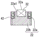
The counter gear 22 includes a support portion 22a inserted into the bearing 42 and a gear portion 22b that is cylindrical and has teeth formed on the outer periphery thereof. The bearing 42 is fitted into a recess constituting the second bearing holder 25 b. The bearing 42 may be held by being bonded to the recess 29.
In the present embodiment, at least a part of the bearing 42 and at least a part of the magnet 32 are disposed to overlap each other when the bearing 42 and the magnet 32 are viewed from the plane in the direction extending from the X axis or the Y axis. In other words, the magnet 32 is disposed in the annular bearing 42. Specifically, the magnet 32 is provided to the recess 22a2, wherein the recess 22a2 is provided to the upper surface 22a1 of the support portion 22a of the counter gear 22. In addition, when viewed from above in the direction extending from the X axis or the Y axis, the encoder 11 is viewed from above from a position away from the encoder 11 in the direction along the X axis or the Y axis.
The entire magnet 32 overlaps the bearing 42 attached to the support portion 22a of the counter gear 22. The upper surface 32a of the magnet 32 is in the same plane as the upper surface 42a of the bearing 42. In addition, the upper surface 32a of the magnet 32 is in the same plane as the upper surface 22a1 of the support portion 22 a. That is, the upper surface 32a of the magnet 32, the upper surface 22a1 of the support portion 22a, and the upper surface 42a of the bearing 42 are respectively in the same plane in the up-down direction.
In the present embodiment, the recess 22a2 corresponds to a "recess".
The same description is also applicable to the mounting structure of the counter gear 23, the magnet 33, and the bearing 43 to the base portion 20. That is, in the present embodiment, the bearing 43 and the magnet 33 are disposed so that at least a part thereof overlaps with each other when viewed from the direction extending from the X axis or the Y axis.
The same description is also made for the mounting structure of counter gear 24, magnet 34, and bearing 44 to base portion 20. That is, in the present embodiment, the bearing 44 and the magnet 34 are disposed so that at least a part thereof overlaps with each other when viewed from the plane in the direction extending along the X axis or the Y axis.
Next, a method of assembling the motor 10 of the present embodiment will be described. That is, a method of attaching the encoder 11 to the motor main body 9 will be described. Fig. 5A and 5B are diagrams illustrating a mounting method of the encoder 11.
As shown in fig. 5A, a unit body 20U having a base portion 20 to which a plurality of counter gears 22, 23, 24, a plurality of magnets 32, 33, 34, and a plurality of bearings 42, 43, 44 are attached is attached to an upper surface 9a of a motor main body 9. Specifically, the unit body 20U is attached to the upper surface 9a of the motor main body 9 by inserting the shaft 5 extending from the motor main body 9 into the through hole 25a1 provided in the first bearing holding portion 25a of the base portion 20.
When the unit body 20U is attached to the motor main body 9, a plurality of counter gears 22, 23, and 24 need to be engaged with the main shaft gear 21 attached to the shaft 5. However, since the plurality of counter gears 22, 23, 24 are attached to the lower side of the unit body 20U, the plurality of counter gears 22, 23, 24 cannot be visually recognized when the unit body 20U is attached.
For example, the inner diameter of the through hole 25a1 is set to substantially match the outer diameter of the shaft 5. In this case, that is, in the case where the shaft bearing 45 is not provided, the unit body 20U into which the shaft 5 is inserted into the through hole 25a1 cannot be moved in the radial direction of the shaft 5, and therefore, it is difficult to mesh the plurality of counter gears 22, 23, 24 and the main gear 21 without visually checking them. Therefore, the work of attaching the encoder 11 to the motor main body 9 becomes very troublesome.
In contrast, in the motor 10 of the present embodiment, as shown in fig. 5A, since the inner diameter of the through hole 25A1 is larger than the outer diameter of the shaft 5, the unit body 20U can move in the radial direction of the shaft 5 in a state where the shaft 5 is inserted into the through hole 25A 1.
Therefore, according to the present embodiment, by moving the unit body 20U in the radial direction of the shaft 5 in the state where the shaft 5 is inserted into the through hole 25a1, the plurality of counter gears 22, 23, 24 attached to the unit body 20U and the main shaft gear 21 attached to the shaft 5 can be easily brought into a meshed state without visual confirmation. Therefore, the work of attaching the encoder 11 to the motor main body 9 is facilitated.
Next, as shown in fig. 5B, the shaft bearing 45 into which the shaft 5 is inserted is fitted into the first bearing holding portion 25a in a state where the plurality of counter gears 22, 23, 24 are meshed with the main shaft gear 21. Thereby fixing the position of the shaft 5 and the base part 20. After the shaft bearing 45 is attached, the unit 20U is fixed to the motor main body 9 by a screw member not shown.
Next, the magnetic detection substrate 12 shown in fig. 3 is attached to the first bearing holding portion 25a of the base portion 20. According to the present embodiment, since the counter gears 22, 23, and 24 and the magnetic detection substrate 12 are fixed to the base portion 20, assembly tolerances can be suppressed as compared with a structure in which these are supported by different members.
Next, after the encoder wheel 14 shown in fig. 3 is mounted to the leading end portion 5b of the shaft 5, the optical sensor substrate 13 is mounted to the base portion 20 (the upper side end surface 26b of the peripheral wall portion 26), thereby completing the mounting of the encoder 11 to the motor main body 9.
According to the encoder 11 of the present embodiment, the magnets 32, 33, 34 are disposed in the bearings 42, 43, 44. That is, the bearings 42, 43, and 44 and the magnets 32, 33, and 34 are arranged to overlap when viewed from the X axis or the Y axis. Therefore, the dimension in the Z axis (first axis) extending in the axis 5 can be reduced as compared with the structure in which the magnets 32, 33, 34 are not disposed in the bearings 42, 43, 44. Therefore, the motor 10 including the encoder 11 is miniaturized in the direction in which the shaft 5 extends.
In addition, according to the robot 1 of the present embodiment, since the motor 10 which is miniaturized in the direction in which the shaft 5 extends is used as the driving unit M, the degree of freedom in designing the driving unit M can be improved.
In the motor 10 of the above embodiment, the case where the magnet 32 is disposed in the recess 22a2 such that the upper surface 32a of the magnet 32 and the upper surface 22a1 of the support portion 22a are in the same plane is exemplified, but the present invention is not limited thereto. The position of the upper surface 32a of the magnet 32 can be changed as appropriate depending on the distance from the magnetic detection substrate 12.
For example, as shown in fig. 6A, the upper surface 32a of the magnet 32 may be disposed in a state of protruding from the upper surface 22a1 of the support portion 22 a. As shown in fig. 6B, the magnet 32 may be completely embedded in the support portion 22a of the counter gear 22.
In the case where the recess 22a2 is formed up to the gear portion 22b, a part of the magnet 32 may overlap the gear portion 22b when viewed from the plane in the direction in which the X axis or the Y axis extends.
Second embodiment
Next, a motor according to a second embodiment will be described. The present embodiment differs from the above-described embodiments in the configuration of the encoder, and is common to the other embodiments. Therefore, the same reference numerals are given to the same components and constituent members as those of the above-described embodiment, and the description thereof will be omitted.
Fig. 7 is a sectional view showing a main part configuration of the motor of the present embodiment. Fig. 7 corresponds to fig. 3 of the first embodiment.
In the present embodiment, the counter gear 22, the magnet 32, and the bearing 42 shown in fig. 7 are also taken as an example, and a mounting structure for mounting the counter gear 22, the magnet 32, and the bearing 42 to the base portion 2 will be described.
As shown in fig. 7, in the encoder 11A of the present embodiment, the magnet 32 is provided in the recess 22b2, and the recess 22b2 is provided on the lower surface 22b1 of the gear portion 22b of the counter gear 22. The entire magnet 32 vertically overlaps with the gear portion 22b of the counter gear 22. The lower surface 32b of the magnet 32 is in the same plane as the upper surface 42a of the gear portion 22 b. In the present embodiment, the recess 22b2 corresponds to a "recess".
The same description applies to the mounting structure for mounting the counter gear 23, the magnet 33, and the bearing 43 to the base portion 20. That is, in the present embodiment, the gear portion of the counter gear 23 and the magnet 33 are arranged so that at least a part thereof overlaps with each other when viewed from the direction extending from the X axis or the Y axis.
The same description can be made for the mounting structure for mounting counter gear 24, magnet 34, and bearing 44 to base portion 20. That is, in the present embodiment, the gear portion of the counter gear 24 and the magnet 34 are arranged so that at least a part thereof overlaps with each other when viewed from the direction extending from the X axis or the Y axis.
According to the encoder 11A of the present embodiment, the magnets 32, 33, 34 are disposed in the respective gear portions of the counter gears 22, 23, 24. That is, when viewed from the plane in the direction extending from the X axis or the Y axis, the magnets 32, 33, and 34 are disposed to overlap the gear portions of the counter gears 22, 23, and 24. Therefore, the dimension in the Z axis (first axis) extending through the shaft 5 can be reduced as compared with a structure in which the magnets 32, 33, 34 are not disposed in the respective gear portions of the counter gears 22, 23, 24. Therefore, according to the motor 10A including the encoder 11A, miniaturization is achieved in the direction in which the shaft 5 extends.
By using the motor 10A for the driving unit of the robot, the degree of freedom in design of the driving unit of the robot can be improved.
In the motor 10A of the present embodiment, the case where the magnet 32 is disposed in the recess 22b2 such that the lower surface 32b of the magnet 32 and the lower surface 22b1 of the gear portion 22b are in one plane is exemplified, but the present invention is not limited to this. The position of the lower surface 32b of the magnet 32 can be changed as appropriate depending on the distance from the magnetic detection substrate 12.
For example, as shown in fig. 8A, the lower surface 32b of the magnet 32 may be disposed so as to protrude from the lower surface 22b1 of the gear portion 22 b. As shown in fig. 8B, the magnet 32 may be completely embedded in the gear portion 22B of the counter gear 22.
In addition, in the case where the recess 22b2 is formed up to the support portion 22a, a part of the magnet 32 may overlap the support portion 22a when viewed from the plane in the direction in which the X axis or the Y axis extends.
The present invention is not limited to the above-described embodiments, and can be modified as appropriate within the scope of the invention.
In the encoders 11 and 11A of the above-described embodiments, the main shaft gear 21 and the counter gears 22, 23, and 24 are disposed below the holding portion 25 of the base portion 20 as an example. That is, the configuration in which the main shaft gear 21 and the counter gears 22, 23, and 24 are disposed below the magnetic detection substrate 12 has been described, but the present invention is not limited to this. The encoder of the present invention may be applied to a case where the main shaft gear 21 and the counter gears 22, 23, and 24 are disposed above the holding portion 25 of the base portion 20, that is, may be applied to a mode where the main shaft gear 21 and the counter gears 22, 23, and 24 are disposed above the magnetic detection substrate 12.
Claims (8)
1. An encoder, comprising:
a base part;
a main shaft gear attached to a shaft portion that rotates;
a counter gear having a cylindrical gear portion meshing with the main gear;
a magnet provided to the counter gear; and
an annular bearing member provided on the base portion and supporting the counter gear,
when a straight line extending along the shaft portion is defined as a first axis and a straight line orthogonal to the first axis is defined as a second axis, the magnet is disposed so as to overlap the bearing member when viewed in plan from a direction in which the second axis extends.
2. The encoder according to claim 1,
the counter gear has a concave portion at a position overlapping with the bearing member when viewed from a direction in which the second shaft extends,
the magnet is disposed in the recess.
3. An encoder, comprising:
a base part;
a main shaft gear attached to a shaft portion that rotates;
a counter gear having a cylindrical gear portion meshing with the main gear;
a magnet provided to the counter gear; and
an annular bearing member provided on the base portion and supporting the counter gear,
when a straight line extending along the shaft portion is defined as a first axis and a straight line orthogonal to the first axis is defined as a second axis, the magnet is arranged to overlap the gear portion when viewed in a plan view from a direction in which the second axis extends.
4. The encoder according to claim 3,
the counter gear has a concave portion at a position overlapping with the gear portion when viewed from a direction in which the second shaft extends in a plan view,
the magnet is disposed in the recess.
5. The encoder according to any of the claims 1 to 4,
the encoder includes a magnetic detection substrate for detecting a change in a magnetic field generated by the magnet,
the magnetic detection substrate is provided to the base portion.
6. The encoder according to claim 5,
the base part is provided with a wall part,
the wall portion is disposed between the magnetic detection substrate and the counter gear.
7. A motor is characterized by comprising:
the encoder of any one of claims 1 to 6.
8. A robot is characterized by comprising:
the motor of claim 7.
Applications Claiming Priority (2)
| Application Number | Priority Date | Filing Date | Title |
|---|---|---|---|
| JP2019073589A JP7272075B2 (en) | 2019-04-08 | 2019-04-08 | Encoders, motors and robots |
| JP2019-073589 | 2019-04-08 |
Publications (1)
| Publication Number | Publication Date |
|---|---|
| CN111795709A true CN111795709A (en) | 2020-10-20 |
Family
ID=72661587
Family Applications (1)
| Application Number | Title | Priority Date | Filing Date |
|---|---|---|---|
| CN202010265653.8A Pending CN111795709A (en) | 2019-04-08 | 2020-04-07 | Encoder, motor and robot |
Country Status (3)
| Country | Link |
|---|---|
| US (1) | US11506679B2 (en) |
| JP (1) | JP7272075B2 (en) |
| CN (1) | CN111795709A (en) |
Cited By (1)
| Publication number | Priority date | Publication date | Assignee | Title |
|---|---|---|---|---|
| CN114543846A (en) * | 2020-11-26 | 2022-05-27 | 精工爱普生株式会社 | Encoder unit, drive device, and robot |
Families Citing this family (1)
| Publication number | Priority date | Publication date | Assignee | Title |
|---|---|---|---|---|
| DE102018214601A1 (en) * | 2018-08-29 | 2020-03-05 | Skf Motion Technologies Ab | System for detecting the position of a linear unit of a linear system |
Citations (12)
| Publication number | Priority date | Publication date | Assignee | Title |
|---|---|---|---|---|
| US20040078166A1 (en) * | 2002-10-18 | 2004-04-22 | Hyundai Mobis, Co., Ltd. | Detection apparatus for steering angle in vehicle |
| CN1929063A (en) * | 2005-09-07 | 2007-03-14 | 索尼株式会社 | Rotating encoder and driving device |
| CN101586940A (en) * | 2008-05-20 | 2009-11-25 | 阿尔卑斯电气株式会社 | Rotary angle detecting device |
| US20110207578A1 (en) * | 2010-02-23 | 2011-08-25 | Avago Technologies Ecbu (Singapore) Pte, Ltd. | Harmonic Gear Multi-Turn Encoder |
| CN102749026A (en) * | 2012-07-10 | 2012-10-24 | 万向钱潮(上海)汽车系统有限公司 | Detection device and method for absolute-type multi-circle rotation angle |
| CN102879024A (en) * | 2011-07-15 | 2013-01-16 | 山洋电气株式会社 | Encoder with gear mechanism and optical encoder device |
| JP2014115234A (en) * | 2012-12-12 | 2014-06-26 | Iai Corp | Mechanical absolute unit, mechanical absolute encoder, and actuator |
| WO2015004873A1 (en) * | 2013-07-10 | 2015-01-15 | パナソニックIpマネジメント株式会社 | Rotation angle detection device |
| US20150338241A1 (en) * | 2014-05-20 | 2015-11-26 | Aisan Kogyo Kabushiki Kaisha | Rotation angle detection apparatus |
| TWM545245U (en) * | 2017-03-28 | 2017-07-11 | 台達電子工業股份有限公司 | Encoder |
| CN206627126U (en) * | 2017-03-28 | 2017-11-10 | 台达电子工业股份有限公司 | Encoder |
| CN208187419U (en) * | 2018-06-07 | 2018-12-04 | 深圳布瑞特科技有限公司 | A kind of multi-turn absolute value encoder |
Family Cites Families (8)
| Publication number | Priority date | Publication date | Assignee | Title |
|---|---|---|---|---|
| JP2006234573A (en) | 2005-02-24 | 2006-09-07 | Tokai Rika Co Ltd | Apparatus for detecting rotation angle |
| JP6819078B2 (en) | 2016-05-30 | 2021-01-27 | セイコーエプソン株式会社 | Encoder, robot, and encoder-integrated motor |
| JP2018136257A (en) | 2017-02-23 | 2018-08-30 | セイコーエプソン株式会社 | Optical scale unit, method for manufacturing optical scale unit, encoder, driving device, robot, and printer |
| JP6934788B2 (en) | 2017-09-19 | 2021-09-15 | ミネベアミツミ株式会社 | Angle detection device, rotation amount identification unit and rotation drive unit |
| JP2019077008A (en) * | 2017-10-26 | 2019-05-23 | セイコーエプソン株式会社 | Scalar robot |
| JP7118628B2 (en) * | 2017-12-01 | 2022-08-16 | キヤノン株式会社 | ROBOT DEVICE AND ROBOT DEVICE CONTROL METHOD |
| JP2019203772A (en) * | 2018-05-23 | 2019-11-28 | ファナック株式会社 | Multi-rotational absolute rotational angle detector and gear |
| JP6770033B2 (en) * | 2018-09-06 | 2020-10-14 | ファナック株式会社 | Encoder rotating member mounting structure and encoder rotating member mounting method |
-
2019
- 2019-04-08 JP JP2019073589A patent/JP7272075B2/en active Active
-
2020
- 2020-04-07 CN CN202010265653.8A patent/CN111795709A/en active Pending
- 2020-04-07 US US16/841,749 patent/US11506679B2/en active Active
Patent Citations (12)
| Publication number | Priority date | Publication date | Assignee | Title |
|---|---|---|---|---|
| US20040078166A1 (en) * | 2002-10-18 | 2004-04-22 | Hyundai Mobis, Co., Ltd. | Detection apparatus for steering angle in vehicle |
| CN1929063A (en) * | 2005-09-07 | 2007-03-14 | 索尼株式会社 | Rotating encoder and driving device |
| CN101586940A (en) * | 2008-05-20 | 2009-11-25 | 阿尔卑斯电气株式会社 | Rotary angle detecting device |
| US20110207578A1 (en) * | 2010-02-23 | 2011-08-25 | Avago Technologies Ecbu (Singapore) Pte, Ltd. | Harmonic Gear Multi-Turn Encoder |
| CN102879024A (en) * | 2011-07-15 | 2013-01-16 | 山洋电气株式会社 | Encoder with gear mechanism and optical encoder device |
| CN102749026A (en) * | 2012-07-10 | 2012-10-24 | 万向钱潮(上海)汽车系统有限公司 | Detection device and method for absolute-type multi-circle rotation angle |
| JP2014115234A (en) * | 2012-12-12 | 2014-06-26 | Iai Corp | Mechanical absolute unit, mechanical absolute encoder, and actuator |
| WO2015004873A1 (en) * | 2013-07-10 | 2015-01-15 | パナソニックIpマネジメント株式会社 | Rotation angle detection device |
| US20150338241A1 (en) * | 2014-05-20 | 2015-11-26 | Aisan Kogyo Kabushiki Kaisha | Rotation angle detection apparatus |
| TWM545245U (en) * | 2017-03-28 | 2017-07-11 | 台達電子工業股份有限公司 | Encoder |
| CN206627126U (en) * | 2017-03-28 | 2017-11-10 | 台达电子工业股份有限公司 | Encoder |
| CN208187419U (en) * | 2018-06-07 | 2018-12-04 | 深圳布瑞特科技有限公司 | A kind of multi-turn absolute value encoder |
Cited By (2)
| Publication number | Priority date | Publication date | Assignee | Title |
|---|---|---|---|---|
| CN114543846A (en) * | 2020-11-26 | 2022-05-27 | 精工爱普生株式会社 | Encoder unit, drive device, and robot |
| US11845182B2 (en) | 2020-11-26 | 2023-12-19 | Seiko Epson Corporation | Encoder unit, drive device, and robot |
Also Published As
| Publication number | Publication date |
|---|---|
| JP2020173115A (en) | 2020-10-22 |
| JP7272075B2 (en) | 2023-05-12 |
| US11506679B2 (en) | 2022-11-22 |
| US20200319224A1 (en) | 2020-10-08 |
Similar Documents
| Publication | Publication Date | Title |
|---|---|---|
| JP5528207B2 (en) | Link actuator | |
| CN111795709A (en) | Encoder, motor and robot | |
| US20170001304A1 (en) | Actuator | |
| EP2821178A1 (en) | Robotic system | |
| US20190283242A1 (en) | Multi-directional drive device, robot joint mechanism, and multi-directional drive method | |
| US10870201B2 (en) | SCARA robot | |
| US20180215036A1 (en) | Robot | |
| WO2019049994A1 (en) | Work machine | |
| CN109668507A (en) | Sensor device | |
| KR101050583B1 (en) | Smart actuator | |
| JP6819078B2 (en) | Encoder, robot, and encoder-integrated motor | |
| JP2017100208A (en) | Robot and robot system | |
| WO2017026468A1 (en) | Work machine provided with parallel link mechanism | |
| JP7427933B2 (en) | drive device | |
| US10744639B2 (en) | Parallel link robot and operation apparatus | |
| US11796045B2 (en) | Strain wave gear with encoder integration | |
| CN108381541B (en) | robot | |
| CN106945031B (en) | Robot single-degree-of-freedom driving module | |
| EP3499690A1 (en) | Motor, actuator, semiconductor manufacturing device, and flat display manufacturing device | |
| JP2021092430A (en) | Encoder, fixing method of encoder cable, and robot | |
| EP3046236A1 (en) | Electric rotating machine | |
| WO2023246995A1 (en) | Robot drive unit for robot joint | |
| WO2015040676A1 (en) | Stopper mechanism, joint mechanism, and robot | |
| JP2023079110A (en) | Robot, method of assembling robot, and robot system | |
| JP2022064162A (en) | Grommet fitting device |
Legal Events
| Date | Code | Title | Description |
|---|---|---|---|
| PB01 | Publication | ||
| PB01 | Publication | ||
| SE01 | Entry into force of request for substantive examination | ||
| SE01 | Entry into force of request for substantive examination |