JP6818020B2 - Systems and methods for tube management - Google Patents
Systems and methods for tube management Download PDFInfo
- Publication number
- JP6818020B2 JP6818020B2 JP2018520107A JP2018520107A JP6818020B2 JP 6818020 B2 JP6818020 B2 JP 6818020B2 JP 2018520107 A JP2018520107 A JP 2018520107A JP 2018520107 A JP2018520107 A JP 2018520107A JP 6818020 B2 JP6818020 B2 JP 6818020B2
- Authority
- JP
- Japan
- Prior art keywords
- tube
- tissue
- flow
- switch
- tubes
- Prior art date
- Legal status (The legal status is an assumption and is not a legal conclusion. Google has not performed a legal analysis and makes no representation as to the accuracy of the status listed.)
- Active
Links
Images


Classifications
-
- A—HUMAN NECESSITIES
- A61—MEDICAL OR VETERINARY SCIENCE; HYGIENE
- A61M—DEVICES FOR INTRODUCING MEDIA INTO, OR ONTO, THE BODY; DEVICES FOR TRANSDUCING BODY MEDIA OR FOR TAKING MEDIA FROM THE BODY; DEVICES FOR PRODUCING OR ENDING SLEEP OR STUPOR
- A61M1/00—Suction or pumping devices for medical purposes; Devices for carrying-off, for treatment of, or for carrying-over, body-liquids; Drainage systems
- A61M1/60—Containers for suction drainage, adapted to be used with an external suction source
-
- A—HUMAN NECESSITIES
- A61—MEDICAL OR VETERINARY SCIENCE; HYGIENE
- A61M—DEVICES FOR INTRODUCING MEDIA INTO, OR ONTO, THE BODY; DEVICES FOR TRANSDUCING BODY MEDIA OR FOR TAKING MEDIA FROM THE BODY; DEVICES FOR PRODUCING OR ENDING SLEEP OR STUPOR
- A61M1/00—Suction or pumping devices for medical purposes; Devices for carrying-off, for treatment of, or for carrying-over, body-liquids; Drainage systems
- A61M1/71—Suction drainage systems
- A61M1/74—Suction control
- A61M1/743—Suction control by changing the cross-section of the line, e.g. flow regulating valves
-
- A—HUMAN NECESSITIES
- A61—MEDICAL OR VETERINARY SCIENCE; HYGIENE
- A61M—DEVICES FOR INTRODUCING MEDIA INTO, OR ONTO, THE BODY; DEVICES FOR TRANSDUCING BODY MEDIA OR FOR TAKING MEDIA FROM THE BODY; DEVICES FOR PRODUCING OR ENDING SLEEP OR STUPOR
- A61M1/00—Suction or pumping devices for medical purposes; Devices for carrying-off, for treatment of, or for carrying-over, body-liquids; Drainage systems
- A61M1/71—Suction drainage systems
- A61M1/77—Suction-irrigation systems
-
- A—HUMAN NECESSITIES
- A61—MEDICAL OR VETERINARY SCIENCE; HYGIENE
- A61M—DEVICES FOR INTRODUCING MEDIA INTO, OR ONTO, THE BODY; DEVICES FOR TRANSDUCING BODY MEDIA OR FOR TAKING MEDIA FROM THE BODY; DEVICES FOR PRODUCING OR ENDING SLEEP OR STUPOR
- A61M1/00—Suction or pumping devices for medical purposes; Devices for carrying-off, for treatment of, or for carrying-over, body-liquids; Drainage systems
- A61M1/89—Suction aspects of liposuction
- A61M1/892—Suction aspects of liposuction with treatment of the collected fat
-
- A—HUMAN NECESSITIES
- A61—MEDICAL OR VETERINARY SCIENCE; HYGIENE
- A61M—DEVICES FOR INTRODUCING MEDIA INTO, OR ONTO, THE BODY; DEVICES FOR TRANSDUCING BODY MEDIA OR FOR TAKING MEDIA FROM THE BODY; DEVICES FOR PRODUCING OR ENDING SLEEP OR STUPOR
- A61M39/00—Tubes, tube connectors, tube couplings, valves, access sites or the like, specially adapted for medical use
- A61M39/10—Tube connectors; Tube couplings
- A61M39/105—Multi-channel connectors or couplings, e.g. for connecting multi-lumen tubes
-
- A—HUMAN NECESSITIES
- A61—MEDICAL OR VETERINARY SCIENCE; HYGIENE
- A61M—DEVICES FOR INTRODUCING MEDIA INTO, OR ONTO, THE BODY; DEVICES FOR TRANSDUCING BODY MEDIA OR FOR TAKING MEDIA FROM THE BODY; DEVICES FOR PRODUCING OR ENDING SLEEP OR STUPOR
- A61M39/00—Tubes, tube connectors, tube couplings, valves, access sites or the like, specially adapted for medical use
- A61M39/22—Valves or arrangement of valves
- A61M39/28—Clamping means for squeezing flexible tubes, e.g. roller clamps
-
- A—HUMAN NECESSITIES
- A61—MEDICAL OR VETERINARY SCIENCE; HYGIENE
- A61B—DIAGNOSIS; SURGERY; IDENTIFICATION
- A61B17/00—Surgical instruments, devices or methods, e.g. tourniquets
- A61B2017/00743—Type of operation; Specification of treatment sites
- A61B2017/00792—Plastic surgery
-
- A—HUMAN NECESSITIES
- A61—MEDICAL OR VETERINARY SCIENCE; HYGIENE
- A61B—DIAGNOSIS; SURGERY; IDENTIFICATION
- A61B18/00—Surgical instruments, devices or methods for transferring non-mechanical forms of energy to or from the body
- A61B2018/00315—Surgical instruments, devices or methods for transferring non-mechanical forms of energy to or from the body for treatment of particular body parts
- A61B2018/00452—Skin
- A61B2018/00458—Deeper parts of the skin, e.g. treatment of vascular disorders or port wine stains
- A61B2018/00464—Subcutaneous fat, e.g. liposuction, lipolysis
-
- A—HUMAN NECESSITIES
- A61—MEDICAL OR VETERINARY SCIENCE; HYGIENE
- A61M—DEVICES FOR INTRODUCING MEDIA INTO, OR ONTO, THE BODY; DEVICES FOR TRANSDUCING BODY MEDIA OR FOR TAKING MEDIA FROM THE BODY; DEVICES FOR PRODUCING OR ENDING SLEEP OR STUPOR
- A61M1/00—Suction or pumping devices for medical purposes; Devices for carrying-off, for treatment of, or for carrying-over, body-liquids; Drainage systems
- A61M1/71—Suction drainage systems
- A61M1/79—Filters for solid matter
-
- A—HUMAN NECESSITIES
- A61—MEDICAL OR VETERINARY SCIENCE; HYGIENE
- A61M—DEVICES FOR INTRODUCING MEDIA INTO, OR ONTO, THE BODY; DEVICES FOR TRANSDUCING BODY MEDIA OR FOR TAKING MEDIA FROM THE BODY; DEVICES FOR PRODUCING OR ENDING SLEEP OR STUPOR
- A61M1/00—Suction or pumping devices for medical purposes; Devices for carrying-off, for treatment of, or for carrying-over, body-liquids; Drainage systems
- A61M1/89—Suction aspects of liposuction
- A61M1/895—Suction aspects of liposuction with means for reinjection of collected fat
-
- A—HUMAN NECESSITIES
- A61—MEDICAL OR VETERINARY SCIENCE; HYGIENE
- A61M—DEVICES FOR INTRODUCING MEDIA INTO, OR ONTO, THE BODY; DEVICES FOR TRANSDUCING BODY MEDIA OR FOR TAKING MEDIA FROM THE BODY; DEVICES FOR PRODUCING OR ENDING SLEEP OR STUPOR
- A61M2202/00—Special media to be introduced, removed or treated
- A61M2202/08—Lipoids
-
- C—CHEMISTRY; METALLURGY
- C12—BIOCHEMISTRY; BEER; SPIRITS; WINE; VINEGAR; MICROBIOLOGY; ENZYMOLOGY; MUTATION OR GENETIC ENGINEERING
- C12M—APPARATUS FOR ENZYMOLOGY OR MICROBIOLOGY; APPARATUS FOR CULTURING MICROORGANISMS FOR PRODUCING BIOMASS, FOR GROWING CELLS OR FOR OBTAINING FERMENTATION OR METABOLIC PRODUCTS, i.e. BIOREACTORS OR FERMENTERS
- C12M45/00—Means for pre-treatment of biological substances
- C12M45/02—Means for pre-treatment of biological substances by mechanical forces; Stirring; Trituration; Comminuting
Description
本出願は、2015年10月21日に出願された米国仮特許出願第62/244,398号の優先権を主張するものであり、参照によりその全体を本明細書に包含する。 This application claims the priority of US Provisional Patent Application No. 62 / 244,398 filed on October 21, 2015, which is incorporated herein by reference in its entirety.
外科手術には、患者と治療システムまたは装置間で、またはシステム及び装置の中で流体、ガス、及び/または組織を輸送するのにチューブ、ホース、または他の導管の使用を必要とするものがある。いくつかの外科手術は、入口及び出口ポートからホースを接続し取り外すことを必要とする多段階工程である。例えば、脂肪組織輸送システムを用いて、外科医は100を越える組み合わせのユーザ動作及び判断を実行する必要があり得る。これらのユーザ動作のいくつかは、吸引源の有効化すること及び無効化すること、または組織格納部及び治療容器への組織または洗浄液を追加することまたは除去することを含む。 Surgery may require the use of tubes, hoses, or other conduits to transport fluids, gases, and / or tissues between the patient and the treatment system or device, or within the system and device. is there. Some surgeries are multi-step processes that require connecting and disconnecting hoses from inlet and outlet ports. For example, using an adipose tissue transport system, the surgeon may need to perform more than 100 combinations of user actions and decisions. Some of these user actions include enabling and disabling the suction source, or adding or removing tissue or lavage fluid to the tissue enclosure and treatment vessel.
いくつかの外科手術においてチューブ接続の状態を追跡し続けることは、術者にとって負担となる。チューブ接続を管理するのに必要なユーザの手間は些細なものではなく、手術を実行する総時間を増加させることがある。色分けといった組織的技術が存在するが、それらは手術中の複数ポイントにおいて個々のチューブの状態を評価する必要性の負担をなくすことができない。 Keeping track of the condition of the tube connection in some surgeries is a burden to the surgeon. The user effort required to manage the tube connection is not trivial and can increase the total time required to perform surgery. Although systematic techniques such as color coding exist, they cannot eliminate the burden of assessing the condition of individual tubes at multiple points during surgery.
本発明の実施形態では、組織処理システムは容器及びチューブ管理装置を含む。容器は、組織保持のための内部容積を取り囲む外壁及び処理組織のためのフィルタを含む。チューブ管理装置は、複数のチューブ貫通孔を有するチューブリストリクタプレート及び複数のチューブ貫通孔を有するチューブスタビライザプレートを含む。複数の流量制限装置は、複数のチューブ貫通孔に隣接するチューブリストリクタプレート上に配置される。チューブ管理装置はさらに、多位置スイッチを含む。複数のチューブは、チューブ貫通孔を貫通する。さらに、多位置スイッチを第1位置に配置することで、患者から内部容積へと組織を輸送するよう複数の流量制限装置に複数のチューブの第1サブセットでの流れを制限させ、多位置スイッチを第2位置に配置することで、内部容積内で組織の処理を可能にするよう複数の流量制限装置に複数のチューブの第2サブセットでの流れを制限させ、かつ多位置スイッチを第3位置に配置することで、組織を内部容積から排出する輸送を可能にするよう複数の流量制限装置に複数のチューブの第3サブセットでの流れを制限させる。 In embodiments of the present invention, the tissue treatment system includes a container and tube management device. The container includes an outer wall surrounding the internal volume for tissue retention and a filter for treated tissue. The tube management device includes a tube restrictor plate having a plurality of tube through holes and a tube stabilizer plate having a plurality of tube through holes. The plurality of flow limiting devices are arranged on a tube restrictor plate adjacent to the plurality of tube through holes. The tube management device also includes a multi-position switch. The plurality of tubes penetrate the tube through holes. In addition, the multiposition switch is placed in the first position to allow multiple flow limiting devices to restrict flow in the first subset of multiple tubes to transport tissue from the patient to the internal volume, thus providing the multiposition switch. Placement in the second position allows multiple flow limiting devices to limit the flow of multiple tubes in the second subset to allow tissue processing within the internal volume, and the multiposition switch in the third position. The arrangement causes the plurality of flow limiting devices to restrict the flow in the third subset of the plurality of tubes so as to allow transport to expel the tissue from the internal volume.
本発明の実施形態では、手術導管の管理方法が記述される。方法は、複数のチューブ及び複数の流量制限装置を本体内に供給し、各流量制限装置は複数のチューブのうちの少なくとも1つの近位にある。方法はさらに、多位置スイッチが第1位置にある時に複数のチューブの第1サブセットでの流れが複数の流量制限装置によって制限され、かつ多位置スイッチが第2位置にある時に第1サブセットとは異なる複数のチューブの第2サブセットでの流れが複数の流量制限装置によって制限された多位置スイッチを供給する。方法はさらに、多位置スイッチの第1位置から多位置スイッチの第2位置に切り替える。 In embodiments of the present invention, methods of managing surgical conduits are described. The method supplies a plurality of tubes and a plurality of flow limiting devices into the body, each flow limiting device being proximal to at least one of the plurality of tubes. The method is further defined as the first subset when the multiposition switch is in the first position and the flow in the first subset of the tubes is restricted by multiple flow limiting devices and the multiposition switch is in the second position. Flow in the second subset of different tubes provides a multi-position switch restricted by multiple flow limiting devices. The method further switches from the first position of the multiposition switch to the second position of the multiposition switch.
本発明の実施形態では、チューブ管理装置は、複数のチューブ貫通孔を有するチューブリストリクタプレート及び複数のチューブ貫通孔を有するチューブスタビライザプレートを含む。複数の流量制限装置は、複数のチューブ貫通孔に隣接するチューブリストリクタプレート上に配置される。チューブ管理装置はさらに、多位置スイッチ及び複数のチューブ貫通孔を貫通する複数のチューブを含む。チューブ管理装置の多位置スイッチを第1位置に配置することで、複数の流量制限装置に複数のチューブの第1サブセットでの流れを制限させ、多位置スイッチを第2位置に配置することで、複数の流量制限装置に複数のチューブの第2サブセットでの流れを制限させ、かつ多位置スイッチを第3位置に配置することで、複数の流量制限装置に複数のチューブの第3サブセットでの流れを制限させる。 In the embodiment of the present invention, the tube management device includes a tube restrictor plate having a plurality of tube through holes and a tube stabilizer plate having a plurality of tube through holes. The plurality of flow limiting devices are arranged on a tube restrictor plate adjacent to the plurality of tube through holes. The tube management device further includes a multi-position switch and a plurality of tubes penetrating the plurality of tube through holes. By arranging the multi-position switch of the tube management device in the first position, the flow limiting devices can restrict the flow of the plurality of tubes in the first subset, and by arranging the multi-position switch in the second position, By restricting the flow in the second subset of multiple tubes to multiple flow limiting devices and arranging the multiposition switch in the third position, the flow limiting devices can flow in the third subset of multiple tubes. To limit.
例示的実施形態の説明
ここで本開示による特定の例示的実施形態を詳細に示し、特定の例が添付の図面に示される。可能な限り、同じ参照番号は同じかまたは類似の部分を指すものとして図面で用いられる。
Description of Exemplary Embodiments Here, specific exemplary embodiments according to the present disclosure are shown in detail, and specific examples are shown in the accompanying drawings. Wherever possible, the same reference numbers are used in the drawings to refer to the same or similar parts.
本出願では、単数形の使用は、特に明記されない限り、複数形を含む。本出願では、「or(または)」の使用は、特に明記されない限り、「and/or(及び/または)」を意味する。さらに、「including(含んでいる)」並びに「included(含まれる)」及び「includes(含む)」といった用語の使用は、限定的ではない。本明細書で用いられる見出しは、構成のためのものであり、記述される主題を限定するものと解釈されるべきではない。本出願に述べられる全ての文書、または文書の一部は、特許、特許出願、記事、書籍、及び論文を含むがこれらに限定せず、あらゆる目的のためにその全体が参照により明確に包含される。 In this application, the use of the singular includes the plural unless otherwise specified. In this application, the use of "or (or)" means "and / or (and / or)" unless otherwise specified. In addition, the use of terms such as "inclusion" and "included" and "includes" is not limiting. The headings used herein are for construction purposes only and should not be construed as limiting the subject matter described. All, or part of, documents referred to in this application, including but not limited to patents, patent applications, articles, books, and treatises, are expressly incorporated by reference in their entirety for any purpose. To.
本明細書に用いられる「脂肪組織」とは、例えば脂肪吸引及び/またはチューセメント脂肪吸引を含むあらゆる方法によって得られた脂肪組織を指す。さらに、脂肪組織は、無処理であってもよく、または、例えば生理食塩水、抗菌剤、洗浄剤、もしくは他の薬剤による洗浄、鎮痛剤、抗菌剤、及び抗炎症剤といった治療薬剤の追加、いくつかの細胞もしくは無細胞成分の除去、または例えば脂肪吸引もしくはチューセメント脂肪吸引中を含む収集処理自体により破壊または改変されてもよい。脂肪組織は、自己移植組織、同種異系組織、または異種組織(ブタの組織)であり得る。 As used herein, "adipose tissue" refers to adipose tissue obtained by any method, including, for example, liposuction and / or liposuction. In addition, the adipose tissue may be untreated, or the addition of therapeutic agents such as saline, antibacterial agents, cleaning agents, or cleaning with other agents, analgesics, antibacterial agents, and anti-inflammatory agents. It may be destroyed or modified by the removal of some cell or cell-free components, or by the collection process itself, including, for example, during liposuction or Chucement liposuction. Adipose tissue can be autotransplanted tissue, allogeneic tissue, or heterologous tissue (pig tissue).
前述のように、外科手術には、患者と治療システムもしくは装置間で、またはシステム及び装置の中で流体、ガス、及び/もしくは組織を輸送するのにチューブ、ホース、または他の導管の使用を必要とするものがある。多段階工程は一般的ではなく、入口及び出口ポートからホースの接続及び解除を必要としてもよい。例えば、脂肪組織輸送及び処理(例えば、脂肪洗浄)のためのシステムは、吸引源を有効化すること及び無効化すること、または組織格納部及び処理容器への組織または洗浄液を追加することまたは除去することを含む、100を越える組み合わせのユーザ動作及び判断を必要とし得る。医療処置中におけるチューブ管理及び確認は、処置が時間依存性構成要素を有する時に特に重要であり得る。 As mentioned above, surgery involves the use of tubes, hoses, or other conduits to transport fluids, gases, and / or tissues between the patient and the treatment system or device, or within the system and device. I have what I need. Multi-step steps are not common and may require the connection and disconnection of hoses from inlet and outlet ports. For example, a system for adipose tissue transport and treatment (eg, adipose lavage) enables and disables suction sources, or adds or removes tissue or lavage fluid to tissue reservoirs and treatment vessels. More than 100 combinations of user actions and judgments may be required, including doing so. Tube management and confirmation during a medical procedure can be particularly important when the procedure has time-dependent components.
様々なヒト及び動物の組織は、患者の治療のための生成物を生成するのに用いられ得る。例えば、様々な疾患及び/または構造的損傷(例えば、外傷、手術、退化、及び/または長期にわたる損耗及び変性)によって損傷を受けたかまたは失われたヒト組織の再生、修復、増大、補強、及び/または治療のために様々な組織生成物が生成されてきた。自己脂肪移植を含む脂肪移植は、美顔術、豊胸術、臀部増大/形成、他の組織部位の増大、腫瘍摘出後の欠陥修正、頭蓋顔面欠陥修正、及び脂肪吸引後の欠陥(窪み)修正を含む様々な医療適用に有用であり得る。 Various human and animal tissues can be used to produce products for the treatment of patients. For example, regeneration, repair, augmentation, reinforcement, and regeneration of human tissue damaged or lost due to various diseases and / or structural injuries (eg, trauma, surgery, degeneration, and / or long-term wear and degeneration). / Or various tissue products have been produced for treatment. Fat transplants, including autologous fat transplants, include facial surgery, breast augmentation, buttock enlargement / formation, enlargement of other tissue sites, defect correction after tumor removal, craniofacial defect correction, and defect (dent) correction after liposuction. Can be useful for a variety of medical applications, including.
自己脂肪移植のための組織を準備する際、組織洗浄及び処理の実行が必要である。移植の工程は通常、シリンジまたはカニューレでの患者からの組織除去といった工程を含む。この組織は、組織の未洗浄成分が分離され得る及び/または組織が様々な溶液を用いて洗浄され得る組織処理容器へと引き出される。一般的なシステムは、濾過及び分離のためのメッシュ、混合ブレードに連結されたクランク、及びいくつかの入口及び出口ポートを含んでもよい。一度組織が十分に準備されると、容器から取り出され、患者へと注入されるかまたは移植され得る。輸送工程中、吸引装置は組織の場所から場所への移動を補助する。しかしながら、処理工程中に吸引圧力を解除することが望まれる。さらに、あらゆる工程中において使用されていない組織輸送チューブは、システムの安定性を維持するために遮断されるべきである。 When preparing tissue for autologous fat transplantation, it is necessary to perform tissue lavage and treatment. The process of transplantation usually involves removing tissue from the patient with a syringe or cannula. This tissue is drawn into a tissue treatment vessel where unwashed components of the tissue can be separated and / or the tissue can be washed with various solutions. A general system may include a mesh for filtration and separation, a crank connected to a mixing blade, and several inlet and outlet ports. Once the tissue is well prepared, it can be removed from the container and injected or transplanted into the patient. During the transport process, the suction device assists in the movement of the tissue from place to place. However, it is desirable to release the suction pressure during the treatment process. In addition, tissue transport tubes that are not used during any process should be blocked to maintain system stability.
図1を参照すると、組織処理システム100の説明的実施形態が示される。示されるように、組織処理システム100は、内部容積を取り囲む外壁110を有する容器を含み得る。容器の内部は、フィルタ、混合ブレード、ホース、及び組織の洗浄及び調整を可能にする他の部品をさらに含み得る。システム100は、システム100の動作を促進するためのチューブ管理装置101を含み得る。チューブは、チューブ管理装置101のポート102を通りシステム100の外部から内部へと通ることができ、チューブ管理装置101内のチューブリストリクタ装置(以下に記述される)は、システム構成のためにチューブを開いたり遮断したりすることを制御し得る。システム構成は、多位置スイッチ103の配置によって決定される。いくつかの実施形態では、システム100は、ユーザが便利に扱うためのキャリーハンドルを備えて提供され得る。
With reference to FIG. 1, a descriptive embodiment of the
本明細書で用いられるとき、「チューブ」、「ホース」、「導管」、または類似の用語は、流体、ガス、及び/または組織生成物がそこを通ることができるよう構成された内腔を有するあらゆる通路と同じ意味で用いられ、それらを指すものと理解されるであろう。 As used herein, the term "tube", "hose", "conduit", or similar term refers to a cavity configured to allow fluids, gases, and / or tissue products to pass through. It is used interchangeably with any passage it has and will be understood to refer to them.
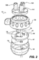
チューブ管理装置101の1つの実施形態における拡大図が図2に示される。チューブ管理装置101は、ポート102a、102b、102c及び多位置スイッチ103を含んでもよい。チューブは、ポート102a、102b、102cを通り、次いでチューブリストリクタプレート104及びチューブスタビライザプレート107を通り、装置101から出ることができる。多位置スイッチ103の位置に基づいて、チューブリストリクタプレート104上のリストリクタ要素105は、流れが各チューブを通すかまたは遮断することを可能にする。いくつかの実施形態では、チューブ管理装置101の内容は、本体を形成する外壁108内に含まれ得る。代替的実施形態では、チューブ管理装置101の部品は、容器110の構造に直接取り付けられ得る。
An enlarged view of one embodiment of the
ポート102a、102b、102cは、様々な構成を有し得る。様々な実施形態に従って、ポート102a、102b、102cは、直線的壁付きもしくは有刺状であるか、ねじ穴付きもしくはねじ穴なしであるか、取付部なし、ルアー取付部、カシメ取付部、または特定の適用に適したあらゆる他のタイプの連結具を有してもよい。ポート102a、102b、102cがチューブ管理装置101の本体から延び出ているように描写されるが、ポートは、孔もしくは窪みを貫通するかもしくは貫通していなくてもよく、または表面から装置101の本体へと内側に延びてもよい。図2では3つのポートのみが描写されるが、あらゆる数のポートが特定の適用に必要な数のチューブに一致するよう選択され得る。これらに限定はされないが、ガス、液体、化学溶液、及び生体組織を含む物質は、多位置スイッチの配置及び医療処置のあらゆる特定工程における必須要件に基づいてポート102a、102b、102cから流れ込む、または流れ出ることができる。
The ports 102a, 102b, 102c can have various configurations. According to various embodiments, the ports 102a, 102b, 102c are straight walled or barbed, threaded or unscrewed, no mounting, luer mounting, caulking, or. You may have any other type of connector suitable for a particular application. Ports 102a, 102b, 102c are depicted as extending from the body of the
多位置スイッチ103の配置は、異なる装置構成中のスイッチに用いられ得る。いくつかの実施形態では、多位置スイッチ103は、回転体またはノブ、及びスイッチ状態を決定する本体の回転角度である。様々な実施形態に従って、多位置スイッチ103は、適切なリンケージを通り、かつ装置を貫通するチューブの開放状態を変更し得るあらゆる機械的または電気的スイッチ(回転的または線形スロースイッチを含む)であってもよい。いくつかの実施形態では、多位置スイッチ103は、ユーザ、特に手術グローブを着用したユーザが容易に操作できるよう補助するノンスリップグリップまたは類似の機能、を含み得る。多位置スイッチ103の配置は、処置中の工程に対応してもよい。例えば、処置中の工程は、脂肪吸引/組織抽出、保持及び混合、潅注、及び吸引/洗浄工程を含んでもよい。
The arrangement of the
チューブリストリクタプレート104は、流量制限装置の使用を通じてプレートのチューブ貫通孔を貫通するチューブを通る流れを遮断するかまたは通すことを可能にする。様々な実施形態に従って、かつ図2及び図3に描写されるように、チューブリストリクタプレート104に、湾曲放射状スロットの形状で流量制限装置105が供給されてもよい。スロット105は、チューブリストリクタプレート104の各角度的配置のためにチューブ上のスロットにおける所望の動作に従って変更するスロット幅を有し得る。例えば、各スロット105は、チューブ内における非制限の流れに対応し、かつチューブ内の流れ遮断を完遂する2つのスロット幅を含んでもよい。あるいは、各スロットは、流量制限の異なるレベルに応じた範囲の幅を有してもよい。
The tube restrictor
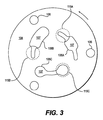
図3では、チューブリストリクタプレート104は、示されたスロット105a、105b、105cを備えたチューブスタビライザプレート107上に重なって示される。図3に示されるチューブリストリクタプレート104の例示的実施形態は、3つの配置を持つ多位置スイッチ103を有するチューブ管理装置101に適した湾曲放射状スロット105a、105b、105cの景況であるチューブ貫通孔を説明する。チューブリストリクタプレート104の湾曲放射状スロット105a、105b、105cは、チューブスタビライザプレート107のチューブ貫通孔115a、115b、115c上のこの上面図に重ねられている。この図では、チューブスタビライザプレート107に対するチューブリストリクタプレート104の配置は、スロット105a、105b、105cをチューブ貫通孔115a、115b、115c上の第1位置に配置する。多位置スイッチの起動により、チューブスタビライザプレート107を適所に置きながらチューブリストリクタプレート104を矢で示された方向に回転させる。その結果、放射状スロットは随時第2または第3位置に前進し得る。様々な実施形態に従って、システム100は、異なる工程を有する異なる処置のために異なる配置のスロット105a、105b、105cを有する複数のチューブリストリクタプレート104を備えて供給され得る。これらの実施形態では、ユーザは、適用に応じて装置101の本体108内に置くための複数のチューブリストリクタプレート104のうちの1つを選択してもよい。
In FIG. 3, the tube
チューブリストリクタプレート104は、多位置スイッチ103と内部係合し得る位置決め機構106を有してもよい。位置決め機構106は、湾曲放射状スロット105a、105b、105cがそれぞれのポート102a、102b、102cと適切に並ぶよう、ユーザがチューブリストリクタプレートを多位置スイッチ103と整列させ、チューブ管理装置101内に置くのを補助し得る。さらに、位置決め機構106は、スイッチの位置がチューブ管理装置101内の適切なチューブ状態を反映するように多位置スイッチの補完機構と一致し得る。いくつかの実施形態では、位置決め機構106は、スイッチが回転する時に同時に移動するよう多位置スイッチ103をチューブリストリクタプレート104に固定し得る。
The tube restrictor
チューブ管理装置101は、チューブスタビライザプレート107を有し得る。チューブスタビライザプレート107は、チューブが貫通できるチューブ貫通孔115を有してもよい。いくつかの実施形態では、チューブスタビライザプレート107における各チューブ貫通孔115の直径は、圧縮することなく各チューブの外側周囲に固定係合できる孔115を貫通する対応チューブの外径と等しいかまたはほぼ等しくてもよい。チューブスタビライザプレート107は、チューブリストリクタプレート104の動作または移動が、チューブの捻れ、再配向、または移動をさせないような位置にチューブを保持し得る。
The
前述のように、システム100は、脂肪組織輸送システムといった外科手術システムに用いられ得る。従って、脂肪組織輸送工程のための例示的判断マトリックス400は、図4に示される。判断マトリックスは、脂肪輸送処理のあらゆる工程中にシステムのあらゆるチューブの開/閉状態を判断するのに用いられてもよい。いくつかの実施形態では、図1に示されるものと類似した組織処理システム100は、医療処置の工程中に解放または遮断される4つのチューブ入口を有し得る。脂肪吸引または吸引402工程では、潅注チューブ及び換気チューブが閉鎖される一方で脂肪吸引カニューレ及び吸引チューブへのチューブは解放されてもよい。保持及び混合または洗浄404工程では、4つ全ての入口が遮断され得る。潅注または輸送406工程では、潅注チューブ及び換気チューブが解放され得る一方で脂肪吸引カニューレ及び吸引チューブへのチューブは閉鎖されてもよい。吸引/洗浄408工程では、吸引チューブ及び換気チューブが解放され得る一方で脂肪吸引カニューレ及び潅注チューブへのチューブは閉鎖されてもよい。
As mentioned above, the
チューブ管理装置501の代替的実施形態が図5に示される。チューブ管理装置501は、ポート502及び多位置スイッチ503を含んでもよい。チューブは、チューブリストリクタプレート504及びチューブスタビライザプレート507を通りポート502から出た後、装置501を通って出る。多位置スイッチの位置に基づいて、チューブリストリクタプレート504上のリストリクタ要素505は、流れが各チューブを通すかまたは遮断することを可能にする。チューブ管理装置501の内容は、本体を形成する外壁508内に含まれ得る。
An alternative embodiment of the
前述の実施形態のように、ポートは様々な構成を有し得る。例えば、ポート502は、直線的壁付きもしくは有刺状であるか、ねじ穴付きもしくはねじ穴なしであるか、取付部なし、ルアー取付部、カシメ取付部、または適用に特化した必須要件に求められるあらゆる他のタイプの連結具を有してもよい。この実施形態ではポート502がチューブ管理装置501の本体から延び出ているように描写されるが、ポートは、窪みもしくは孔を貫通するかもしくは貫通していなくてもよく、または表面から装置501の本体へと内側に延びてもよい。図5では3つのポートのみが描写されるが、あらゆる数のポートが特定の適用に必要な数のチューブに一致するよう選択され得る。これらに限定はされないが、ガス、液体、化学溶液、及び生体組織を含む物質は、多位置スイッチの配置及び手術処置のあらゆる特定工程における必須要件に応じてポート502から流れ込む、または流れ出ることができる。
As in the embodiments described above, the port can have various configurations. For example,
多位置スイッチ503の配置は、異なる装置構成中のスイッチに用いられ得る。いくつかの実施形態では、多位置スイッチ503は、回転体またはノブ、及びスイッチ状態を決定する本体の回転角度である。様々な実施形態に従って、多位置スイッチ503は、適切なリンケージを通り、装置を貫通するチューブの開放状態を変更し得るあらゆる機械的または電気的スイッチ(回転的または線形スロースイッチを含む)であってもよい。いくつかの実施形態では、多位置スイッチ503は、ユーザ、特に手術グローブを着用したユーザが容易に操作できるよう補助するノンスリップグリップまたは類似の機能、を含み得る。多位置スイッチ503の配置は、処置中の工程に対応してもよい。例えば、処置中の工程は、脂肪吸引/組織抽出、保持及び混合、潅注、ならびに吸引/洗浄工程を含んでもよい。
The arrangement of the
チューブリストリクタプレート504は、流量制限装置の使用を通じてプレートのチューブ貫通孔516を貫通するチューブを通る流れを遮断するかまたは通すことを可能にする。チューブリストリクタプレート504は、中心部504bと回転可能に係合する外部リング504aを含んでもよい。チューブは、流量制限装置に隣接するチューブ貫通孔516を通りチューブリストリクタプレート504を貫通し得る。様々な実施形態に従って、かつ図5に描写されるように、チューブリストリクタプレート504は、中心部504b上の湾曲中心ハブ512及び外部リング504aに取り付けられた一体型ばね514を介してハブ512に対してチューブを押し進めるスライディングブロック505の形状で流量制限装置が供給されてもよい。スライディングブロック505は、平面なプレート、シリンダ、楕円、球体、卵形構成、または適用に特化した必須要件を満たすあらゆる他の形状であってもよい。いくつかの実施形態では、湾曲中心ハブ512は、ポート502の数と等しい数の窪みを有してもよく、かつ各チューブは湾曲中心ハブの窪みに隣接するチューブ貫通孔516を貫通してもよい。一体型ばね512に取り付けられたスライディングブロック505が湾曲中心ハブ512の窪みと並ぶ時、ばねの力はスライディングブロックを延ばし、それをチューブに対して押し進めてもよい。いくつかの実施形態では、チューブリストリクションプレート504の中心部504bは、チューブスタビライザプレート507に固定して取り付けられてもよい。多位置スイッチ503が1つの位置から他の位置へと変化するにつれて、チューブリストリクションプレート504の外部リング504aは回転してもよい一方で湾曲した中心ハブ512を含む中心部504bはチューブスタビライザプレート507に対して回転しない。
The tube restrictor
様々な実施形態に従って、外部リング504aは、一方向ラチェット機構509を備えて供給されてもよい。ラチェット機構の歯は、外部リング504aの回転を一方向へは可能にしながらも反対方向への回転を防ぐように、チューブリストリクションプレート504の中心部504b上に配置された歯止め511と係合し得る。この実施形態では歯止め511が中心部504b上に配置されているように描写されるが、歯止めが多位置スイッチ503またはチューブスタビライザプレート507の内部といったチューブ管理装置501全体における他のポイントに取り付けられ得ることが当業者には明らかとなろう。
According to various embodiments, the outer ring 504a may be supplied with a one-
チューブ管理装置501はさらに、チューブスタビライザプレート507を有し得る。チューブスタビライザプレート507は、チューブが貫通できるチューブ貫通孔515を有してもよい。いくつかの実施形態では、チューブスタビライザプレート507における各チューブ貫通孔515の直径は、圧縮することなく各チューブの外側周囲に固定係合できる孔を貫通する対応チューブの外径と等しくてもよい。チューブスタビライザプレート507は、チューブリストリクタプレート504の動作または移動が、チューブの捻れ、再配向、または移動をさせないような位置にチューブを保持し得る。
The
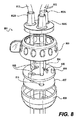
チューブ管理装置の他の実施形態が図6に示される。チューブ管理装置601は、ポート602及び多位置スイッチ603を含み得る。装置601は、チューブスタビライザプレート607及び流量制限装置を含むチューブリストリクタプレート604を含み得る。装置601の部品は、本体608内に収容され得る。
Another embodiment of the tube management device is shown in FIG. The
ポート602は、チューブ管理装置601と外界の間に接続される。様々な実施形態に従って、ポート602は、直線的壁付きもしくは有刺状であるか、ねじ穴付きもしくはねじ穴なしであるか、取付部なし、ルアー取付部、カシメ取付部、または適用に特化した必須要件に求められるあらゆる他のタイプの連結具を有してもよい。この実施形態ではポート602がチューブ管理装置601の本体から延び出ているように描写されるが、ポートは、孔を貫通するかまたは貫通していなくてもよく、または装置表面から装置601の本体へと内側に延びてもよい。図6では3つのポートのみが描写されるが、あらゆる数のポート602が特定の適用に必要な数のチューブと一致するよう選択され得ることが当業者には明らかとなるだろう。これらに限定はされないが、ガス、液体、化学溶液、及び生体組織を含む流体は、多位置スイッチの配置及び医療処置のあらゆる特定工程における必須要件に応じてポート602から流れ込む、または流れ出ることができる。
The
多位置スイッチ603の配置は、異なる装置構成中のスイッチに用いられ得る。いくつかの実施形態では、多位置スイッチ603は、回転体またはノブ、及びスイッチ状態を決定する本体の回転角度である。様々な実施形態に従って、多位置スイッチ603は、適切なリンケージを通り、装置を貫通するチューブの開放状態を変更し得るあらゆる機械的または電気的スイッチ(回転的または線形スロースイッチを含む)であってもよい。いくつかの実施形態では、多位置スイッチ603は、ユーザ、特に手術グローブを着用したユーザが容易に操作できるよう補助するノンスリップグリップまたは類似の機能、を含み得る。多位置スイッチ603の配置は、処置中の工程に対応してもよい。例えば、処置中の工程は、脂肪吸引/組織抽出、保持及び混合、潅注、ならびに吸引/洗浄工程を含んでもよい。
The arrangement of the
チューブリストリクタプレート604は、中心部604bと回転可能に係合する外部リング604aを含んでもよい。チューブは、流量制限装置に隣接するチューブ貫通孔616を貫通してもよい。様々な実施形態に従って、かつ図6に描写されるように、チューブリストリクタプレート604は、中心部604b上の湾曲中心ハブ612及び外部リング604aに取り付けられた一体型ばね614を介してハブ612に対してチューブを押し進めるスライディングブロック605の形状で流量制限装置を供給されてもよい。スライディングブロック605は、平面なプレート、シリンダ、楕円、球体、卵形、または適用に特化した必須要件を満たすあらゆる他の形状であってもよい。いくつかの実施形態では、湾曲中心ハブ612は、ポート602の数と等しい数の窪みを有してもよく、かつ各チューブは湾曲中心ハブの窪みに隣接するチューブ貫通孔616を貫通してもよい。一体型ばね612に取り付けられたスライディングブロック605が湾曲中心ハブ612の窪みと並ぶ時、ばねの力はスライディングブロックを延ばし、それをチューブに対して押し進めてもよい。多位置スイッチ603が1つの位置から他の位置へと変化するにつれて、チューブリストリクションプレート604の外部リング604aは回転してもよい一方で湾曲中心ハブ612を含む中心部604bはチューブスタビライザプレート607に対して回転しない。様々な実施形態に従って、スライディングブロック605及び一体型ばね614は、スペーサ604cを用いて異なる放射状深さで配置され得る。
The tube restrictor
チューブ管理装置601は、いくつかの実施形態ではチューブスタビライザプレート607を有し得る。チューブスタビライザプレート607は、チューブが貫通できるチューブ貫通孔615を有してもよい。好適な実施形態では、チューブスタビライザプレート607における各チューブ貫通孔615の直径は、圧縮することなく各チューブの外側周囲に固定係合できる孔を貫通する対応チューブの外径と等しいかまたはほぼ等しくてもよい。チューブスタビライザプレート607は、チューブリストリクタプレート604の動作または移動が、チューブの捻れ、再配向、または移動をさせないような位置にチューブを保持し得る。
The
図6の実施形態におけるチューブスタビライザプレート607に重なるチューブリストリクタプレート604の上面図が、図7に示される。様々な実施形態に従って、チューブリストリクタプレート604は、チューブが中心部604bの湾曲中心ハブ612に対して、かつ流量制限装置に関連して位置を変更できるようにスロット613を有し得る。この方法では、チューブリストリクタプレート604の単一実施形態は2つ以上の構成で用いられ得る。チューブが位置「内」にある時、チューブは湾曲中心ハブ612の窪み付近を通過し、外部リング604aから延びるスペーサ604cに取り付けられたスライディングブロック605によって閉鎖され得る。チューブが位置「外」にある時、チューブは湾曲中心ハブ612の延長部付近を通過する。この位置では、チューブは、一体型ばね614によって外部リング604aに直接取り付けられるスライディングブロック505によって閉鎖され得る。好適な実施形態では、スペーサ604cなしで外部リング604aに直接取り付けられたスライディングブロック605は、チューブを湾曲中心ハブ612の窪みに隣接するに至らせることができない。
A top view of the tube
様々な実施形態に従って、外部リング604aは、一方向ラチェット機構609を供給されてもよい。ラチェット機構の歯は、外部リング604aの回転を一方向へは可能にしながらも反対方向への回転を防ぐように、チューブリストリクションプレート604の中心部604b上に配置された歯止め611と係合し得る。この実施形態では歯止め611が中心部604b上に配置されているように描写されるが、歯止めが多位置スイッチ603またはチューブスタビライザプレート607の内部といったチューブ管理装置601全体における他のポイントに取り付けられ得ることが当業者には明らかとなるだろう。
According to various embodiments, the outer ring 604a may be supplied with a
手術導管を管理する方法がさらに発明者らによって想定される。方法は、本体内に複数のチューブ及び複数の流量制限装置を供給すること、ここで各流量制限装置はチューブの少なくとも1つの近位にあり、さらに多位置スイッチを供給すること、とを含み、スイッチが第1位置にある時に流れはチューブの第1サブセットで流量制限装置によって制限され、スイッチが第2位置にある時に流れは第1サブセットとは異なるチューブの第2サブセットで流量制限装置によって制限される。方法はさらに、多位置スイッチの第1位置から第2位置に切り替えることを含む。 Methods for managing surgical conduits are further envisioned by the inventors. The method comprises supplying multiple tubes and multiple flow limiting devices within the body, where each flow limiting device is at least one proximal to the tube and further supplies a multi-position switch. When the switch is in the first position, the flow is restricted by the flow limiting device in the first subset of the tube, and when the switch is in the second position, the flow is restricted by the flow limiting device in the second subset of the tube, which is different from the first subset. Will be done. The method further comprises switching from the first position to the second position of the multiposition switch.
各流量制限装置がチューブの少なくとも1つの近位にあるところで複数のチューブ及び複数の流量制限装置を本体内に供給する工程は、図1〜3に関連して前述のようにチューブがポート102を貫通してチューブ管理装置101の流量制限装置105を通過することを含んでもよいが、これに限定はされない。
The step of supplying the plurality of tubes and the plurality of flow rate limiting devices into the main body where each flow limiting device is at least one proximal to the tube is such that the tube connects the
スイッチが第1位置にある時に流れを流量制限装置によってチューブの第1サブセットで制限し、スイッチが第2位置にある時に流れを流量制限装置によって第1サブセットとは異なるチューブの第2サブセットで制限する、多位置スイッチを供給する工程は、図1〜3に関連して前述のようにチューブ管理装置101内に多位置スイッチ103を供給することを含んでもよいが、これに限定はされない。
When the switch is in the first position, the flow limiting device limits the flow with the first subset of tubes, and when the switch is in the second position, the flow limiting device limits the flow with a second subset of tubes different from the first subset. The step of supplying the multi-position switch may include, but is not limited to, supplying the
多位置スイッチの第1位置から第2位置へと切り替える工程は、図1及び2に関連して前述のように多位置スイッチ103を第1位置から第2位置へと切り替えることを含んでもよいが、これに限定はされない。
The step of switching from the first position to the second position of the multi-position switch may include switching the
チューブ管理装置801の代替的実施形態における拡大図が図8に示される。チューブ管理装置801は、ポート802a、802b、802c及び多位置スイッチ803を含んでもよい。チューブ812は、ポート802a、802b、802cを貫通し、その後、チューブリストリクタプレート804及びチューブスタビライザプレート807を通り、装置801から出る。多位置スイッチ803の位置に基づいて、チューブリストリクタプレート804上のリストリクタ要素805は、流れが各チューブ812を通すかまたは遮断することを可能にする。いくつかの実施形態では、チューブ管理装置801の内容は、本体を形成する外壁808内に含まれ得る。
An enlarged view of an alternative embodiment of the
ポート802a、802b、802cは、図2に関連して前述のように様々な構成を有し得る。様々な実施形態に従って、ポート802a、802b、802cは、直線的壁付きもしくは有刺状であるか、ねじ穴付きもしくはねじ穴なしであるか、取付部なし、ルアー取付部、カシメ取付部、または特定の適用に適したあらゆる他のタイプの連結具を有してもよい。ポート802a、802b、802cがチューブ管理装置801の本体から延び出ているように描写されるが、ポートは、孔または窪みを貫通するかまたは貫通していなくてもよく、または表面から装置801の本体へと内側に延びてもよい。図8では3つのポートのみが描写されるが、あらゆる数のポートが特定の適用に必要な数のチューブ812に一致するよう選択され得る。これらに限定はされないが、ガス、液体、化学溶液、及び生体組織を含む物質は、多位置スイッチの配置及び医療処置のあらゆる特定工程における必須要件に応じてポート802a、802b、802cを貫通するチューブ812から流れ出る、または流れ込むことができる。
The ports 802a, 802b, 802c may have various configurations as described above in connection with FIG. According to various embodiments, the ports 802a, 802b, 802c are straight walled or barbed, threaded or unscrewed, no mounting, luer mounting, caulking, or. You may have any other type of connector suitable for a particular application. Ports 802a, 802b, 802c are depicted as extending from the body of the
図2を参照して前述したように、多位置スイッチ803の配置は、異なる装置構成中のスイッチに用いられ得る。いくつかの実施形態では、多位置スイッチ803は、回転体またはノブ、及びスイッチ状態を決定する本体の回転角度である。様々な実施形態に従って、多位置スイッチ803は、適切なリンケージを通り、チューブ812の開放状態を変更し得るあらゆる機械的または電気的スイッチ(回転的または線形スロースイッチを含む)であってもよい。いくつかの実施形態では、多位置スイッチ803は、ユーザ、特に手術グローブを着用したユーザが容易に操作できるよう補助するノンスリップグリップまたは類似の機能を含み得る。多位置スイッチ803の配置は、処置中の工程に対応してもよい。例えば、処置中の工程は、脂肪吸引/組織抽出、保持及び混合、潅注、ならびに吸引/洗浄工程を含んでもよい。
As described above with reference to FIG. 2, the arrangement of the
チューブリストリクタプレート804は、流量制限装置の使用を通じてプレートを貫通するにつれてチューブ812を通る流れを遮断するかまたは通すことを可能にする。図2及び図3に描写される実施形態に類似して、チューブリストリクタプレート804は、湾曲放射状スロット805の形状で流量制限装置及びチューブ貫通孔を供給されてもよい。代替的実施形態では、流量制限装置は、図5及び図6の実施形態を参照して前述したものと類似し得る。スロット805は、チューブリストリクタプレート804の各角度的配置のためにチューブ812上のスロットにおける所望の動作に従って変更するスロット幅を有し得る。例えば、各スロット805は、チューブ812内における非制限の流れに対応し、かつチューブ812内の流れ遮断を完遂する2つのスロット幅を含んでもよい。あるいは、各スロットは、流量制限の異なるレベルに応じた範囲の幅を有してもよい。
The tube restrictor
チューブリストリクタプレート804は、多位置スイッチ803と内部係合し得る位置決め機構806を有してもよい。位置決め機構806は、湾曲放射状スロット805がそれぞれのポート802a、802b、802cと適切に並ぶよう、ユーザがチューブリストリクタプレート804を多位置スイッチ803と整列させ、チューブ管理装置801内に置くのを補助し得る。さらに、位置決め機構806は、スイッチの位置がチューブ管理装置801内の適切なチューブ状態を反映するように多位置スイッチの補完機構と一致し得る。いくつかの実施形態では、位置決め機構806は、スイッチが回転する時に同時に移動するよう多位置スイッチ803をチューブリストリクタプレート804に固定し得る。
The tube restrictor
チューブ管理装置801は、チューブスタビライザプレート807を有し得る。チューブスタビライザプレート807は、チューブが貫通できるチューブ貫通孔815を有してもよい。いくつかの実施形態では、チューブスタビライザプレート807における各チューブ貫通孔815の直径は、圧縮することなく各チューブの外側周囲に固定係合できる孔を貫通する対応チューブの外径と等しいかまたはほぼ等しくてもよい。チューブスタビライザプレート807は、チューブリストリクタプレート804の動作または移動が、チューブの捻れ、再配向、または移動をさせないような位置にチューブを保持し得る。
The
チューブ管理装置801のチューブ812は、適用に特化した必須要件を満たすあらゆる素材で作られ得る。チューブ812は、例えば、PVC、高密度ポリエチレン、ナイロン、ラテックス、シリコン、ポリウレタン、TYGON(登録商標)、またはあらゆる非反応性チューブまたはホースで作られ得るが、これらに限定はされない。図8に描写されるように、チューブ812は、ポート802a、802b、802cから出て延びてもよく、またはポート802a、802b、802c内もしくはそれらより下で終結してもよい。チューブ812は、例えば、ポート802a、802b、802cもしくは本体808といったチューブ管理装置801に永続的に取り付けられてもよく、またはチューブ812は取り外し可能及び/もしくは再配置可能であってもよい。様々な実施形態に従って、チューブ812は、複数処置のためにチューブ管理装置801の再利用を可能にするよう、各処置後に廃棄され、新しいチューブ812と取り替えられてもよい。
The
本発明が好適な実施形態に関連して本明細書に記述されてきたが、当業者は添付の特許請求の範囲及びそのあらゆる均等物の範囲内に含まれると意図される、本明細書に記載されるシステム及び方法への変更、置き換えまたは均等物を生じさせ得る。 Although the present invention has been described herein in the context of preferred embodiments, those skilled in the art are intended to be within the scope of the appended claims and all equivalents thereof. Changes, replacements or equivalents to the described systems and methods may occur.
Claims (12)
容器であって、
組織保持のための内部容積を取り囲む外壁と、
組織処理のためのフィルタとを含む、前記容器と、
チューブ管理装置であって、
複数のチューブ貫通孔を有するチューブリストリクタプレートと、
複数のチューブ貫通孔を有するチューブスタビライザプレートと、
複数の流量制限装置であって、前記複数のチューブ貫通孔に隣接する前記チューブリストリクタプレート上に配置された湾曲放射状スロットを含む複数の流量制限装置と、
多位置スイッチと含む、前記チューブ管理装置とを備える、前記システムであって、
複数のチューブは前記チューブ貫通孔を貫通し、かつ前記多位置スイッチを第1位置に配置することで、患者から前記内部容積へと組織を輸送するよう前記複数の流量制限装置に前記複数のチューブの第1サブセットでの流れを制限させ、前記多位置スイッチを第2位置に配置することで、前記内部容積内で前記組織の処理を可能にするよう前記複数の流量制限装置に前記複数のチューブの第2サブセットでの流れを制限させ、かつ前記多位置スイッチを第3位置に配置することで、前記組織を前記内部容積から排出する輸送を可能にするよう前記複数の流量制限装置に前記複数のチューブの第3サブセットでの流れを制限させる、前記システム。 It is an organizational processing system
It ’s a container,
The outer wall surrounding the internal volume for tissue retention,
The container, including a filter for tissue treatment, and
It is a tube management device
A tube restrictor plate with multiple tube through holes and
A tube stabilizer plate with multiple tube through holes and
A plurality of flow rate limiting devices including a curved radial slot arranged on the tube restrictor plate adjacent to the plurality of tube through holes.
The system comprising the tube management device, including a multi-position switch.
The plurality of tubes penetrate the tube through hole and the plurality of tubes are placed in the plurality of flow limiting devices so as to transport tissue from the patient to the internal volume by arranging the multi-position switch in the first position. The plurality of tubes in the plurality of flow limiting devices so as to allow processing of the tissue within the internal volume by limiting the flow in the first subset of and placing the multiposition switch in the second position. By limiting the flow in the second subset of the above and by arranging the multiposition switch in the third position, the plurality of flow limiting devices are provided with the plurality of flow limiting devices so as to enable transportation for discharging the tissue from the internal volume. The system that restricts flow in a third subset of tubes.
Applications Claiming Priority (3)
| Application Number | Priority Date | Filing Date | Title |
|---|---|---|---|
| US201562244398P | 2015-10-21 | 2015-10-21 | |
| US62/244,398 | 2015-10-21 | ||
| PCT/US2016/058158 WO2017070493A1 (en) | 2015-10-21 | 2016-10-21 | Systems and methods for tube management |
Related Child Applications (1)
| Application Number | Title | Priority Date | Filing Date |
|---|---|---|---|
| JP2020216317A Division JP2021058661A (en) | 2015-10-21 | 2020-12-25 | Systems and methods for tube management |
Publications (3)
| Publication Number | Publication Date |
|---|---|
| JP2018538024A JP2018538024A (en) | 2018-12-27 |
| JP2018538024A5 JP2018538024A5 (en) | 2019-10-31 |
| JP6818020B2 true JP6818020B2 (en) | 2021-01-20 |
Family
ID=57233901
Family Applications (2)
| Application Number | Title | Priority Date | Filing Date |
|---|---|---|---|
| JP2018520107A Active JP6818020B2 (en) | 2015-10-21 | 2016-10-21 | Systems and methods for tube management |
| JP2020216317A Withdrawn JP2021058661A (en) | 2015-10-21 | 2020-12-25 | Systems and methods for tube management |
Family Applications After (1)
| Application Number | Title | Priority Date | Filing Date |
|---|---|---|---|
| JP2020216317A Withdrawn JP2021058661A (en) | 2015-10-21 | 2020-12-25 | Systems and methods for tube management |
Country Status (12)
| Country | Link |
|---|---|
| US (2) | US10286122B2 (en) |
| EP (2) | EP3633027A1 (en) |
| JP (2) | JP6818020B2 (en) |
| KR (1) | KR20180072729A (en) |
| CN (1) | CN108350424A (en) |
| AU (1) | AU2016342002A1 (en) |
| BR (1) | BR112018008050A2 (en) |
| CA (1) | CA3002078A1 (en) |
| ES (1) | ES2775597T3 (en) |
| MX (1) | MX2018004956A (en) |
| RU (1) | RU2728767C2 (en) |
| WO (1) | WO2017070493A1 (en) |
Families Citing this family (6)
| Publication number | Priority date | Publication date | Assignee | Title |
|---|---|---|---|---|
| EP2834344B1 (en) | 2012-09-06 | 2016-07-20 | The GID Group, Inc. | Tissue processing apparatus and method for processing adipose tissue |
| US9248384B2 (en) | 2013-10-02 | 2016-02-02 | Allergan, Inc. | Fat processing system |
| CN108291201A (en) | 2015-10-21 | 2018-07-17 | 生命细胞公司 | System and method for medical treatment device control |
| US10472603B2 (en) | 2016-08-30 | 2019-11-12 | Lifecell Corporation | Systems and methods for medical device control |
| CN112739294A (en) * | 2018-09-19 | 2021-04-30 | 帝皇工业有限公司 | Pipe fitting connecting system for negative pressure wound treatment |
| KR20230146293A (en) * | 2022-04-12 | 2023-10-19 | 연세대학교 산학협력단 | Wound retractor inserter |
Family Cites Families (104)
| Publication number | Priority date | Publication date | Assignee | Title |
|---|---|---|---|---|
| US3791524A (en) * | 1972-04-13 | 1974-02-12 | Atomic Energy Commission | Tissue collector |
| US3855997A (en) * | 1973-07-11 | 1974-12-24 | Cinco Medical Health Supply Co | Sterile specimen trap |
| US4681571A (en) | 1981-04-23 | 1987-07-21 | C. R. Bard, Inc. | Suction canister with disposable liner and check valve |
| US4457339A (en) * | 1982-03-03 | 1984-07-03 | Coulter Electronics, Inc. | Multiprogrammable pinch valve module |
| JPS6040067A (en) * | 1983-08-15 | 1985-03-02 | テルモ株式会社 | Medical container |
| US5372945A (en) | 1985-06-06 | 1994-12-13 | Alchas; Paul G. | Device and method for collecting and processing fat tissue and procuring microvessel endothelial cells to produce endothelial cell product |
| US4753634A (en) | 1986-10-31 | 1988-06-28 | Johnson Gerald W | Fat collection syringe |
| US4821996A (en) * | 1987-01-28 | 1989-04-18 | Baxter Travenol Laboratories, Inc. | Fluid flow control valve and transfer set |
| SE8801098D0 (en) | 1988-03-24 | 1988-03-24 | Pharmacia Ab | APPARATUS AND METHOD FOR AUTOMATIC EXTRACTION OF EXTRA-CHROMOSOMAL DNA FROM A CELL SUSPENSION IN A CONTAINER |
| US4988623A (en) | 1988-06-30 | 1991-01-29 | The United States Of America As Represented By The Administrator Of The National Aeronautics And Space Administration | Rotating bio-reactor cell culture apparatus |
| US5301685A (en) | 1989-01-10 | 1994-04-12 | Guirguis Raouf A | Method and apparatus for obtaining a cytology monolayer |
| US5601707A (en) | 1990-07-13 | 1997-02-11 | Isco, Inc. | Apparatus and method for supercritical fluid extraction or supercritical fluid chromatography |
| US5336616A (en) | 1990-09-12 | 1994-08-09 | Lifecell Corporation | Method for processing and preserving collagen-based tissues for transplantation |
| NZ242533A (en) | 1991-05-03 | 1995-05-26 | Becton Dickinson Co | Device for collecting and processing fat tissue; vessel with rinsing and digesting chamber, drain chamber and isolation chamber |
| US5610074A (en) | 1993-02-24 | 1997-03-11 | Beritashvili; David R. | Centrifugal method and apparatus for isolating a substance from a mixture of substances in a sample liquid |
| US5409833A (en) | 1993-07-01 | 1995-04-25 | Baxter International Inc. | Microvessel cell isolation apparatus |
| RU2116802C1 (en) * | 1994-08-09 | 1998-08-10 | Московский областной научно-исследовательский клинический институт | Device for washing abdominal cavity |
| US5888409A (en) | 1995-06-07 | 1999-03-30 | Cedars-Sinai Medical Center | Methods for cell isolation and collection |
| US6200606B1 (en) | 1996-01-16 | 2001-03-13 | Depuy Orthopaedics, Inc. | Isolation of precursor cells from hematopoietic and nonhematopoietic tissues and their use in vivo bone and cartilage regeneration |
| US5785640A (en) | 1996-05-23 | 1998-07-28 | Kresch; Arnold J. | Method for treating female incontinence |
| US5901717A (en) | 1996-08-16 | 1999-05-11 | Dornoch Medical Systems, Inc. | Liquid waste disposal and canister flushing system and method |
| US5911700A (en) | 1997-03-11 | 1999-06-15 | Microaire Surgical Instruments | Power assisted liposuction and lipoinjection equipment |
| US5786207A (en) | 1997-05-28 | 1998-07-28 | University Of Pittsburgh | Tissue dissociating system and method |
| AU8476698A (en) | 1997-07-03 | 1999-01-25 | Osiris Therapeutics, Inc. | Human mesenchymal stem cells from peripheral blood |
| USD401336S (en) | 1997-07-24 | 1998-11-17 | Somnus Medical Technologies, Inc. | Tissue ablation device |
| JP3965796B2 (en) * | 1997-08-19 | 2007-08-29 | 株式会社ジェイ・エム・エス | Medical fluid flow switching device |
| US5853398A (en) * | 1997-12-19 | 1998-12-29 | Baxter International Inc. | Container with pivoting tube clamp |
| EP1060242A4 (en) | 1998-01-23 | 2003-09-17 | Imclone Systems Inc | Purified populations of stem cells |
| USD424194S (en) | 1998-10-16 | 2000-05-02 | Bio-Plexus, Inc. | Catheter needle assembly |
| US20010030152A1 (en) | 1999-12-20 | 2001-10-18 | Wright David A. | Compound mixer and filter for lapping machine |
| US6733537B1 (en) | 2000-06-02 | 2004-05-11 | Reconstructive Technologies, Inc. | Apparatus for tissue expansion using pulsatile motion |
| CN1187356C (en) | 2000-11-22 | 2005-02-02 | 南宁枫叶药业有限公司 | System for extracting tetradoxin with high yield |
| US6544788B2 (en) | 2001-02-15 | 2003-04-08 | Vijay Singh | Disposable perfusion bioreactor for cell culture |
| US6626890B2 (en) | 2001-06-06 | 2003-09-30 | Tony R. Brown | Fat removal device and method |
| US7172572B2 (en) | 2001-10-04 | 2007-02-06 | Boston Scientific Scimed, Inc. | Manifold system for a medical device |
| US7264608B2 (en) | 2001-12-05 | 2007-09-04 | Fenwal, Inc. | Manual processing systems and methods for providing blood components conditioned for pathogen inactivation |
| US7514075B2 (en) | 2001-12-07 | 2009-04-07 | Cytori Therapeutics, Inc. | Systems and methods for separating and concentrating adipose derived stem cells from tissue |
| US7595043B2 (en) | 2001-12-07 | 2009-09-29 | Cytori Therapeutics, Inc. | Method for processing and using adipose-derived stem cells |
| DK1921133T3 (en) | 2001-12-07 | 2015-08-24 | Cytori Therapeutics Inc | System for processing lipoaspiratceller |
| US7585670B2 (en) | 2001-12-07 | 2009-09-08 | Cytori Therapeutics, Inc. | Automated methods for isolating and using clinically safe adipose derived regenerative cells |
| US7651684B2 (en) | 2001-12-07 | 2010-01-26 | Cytori Therapeutics, Inc. | Methods of using adipose tissue-derived cells in augmenting autologous fat transfer |
| US9144583B2 (en) | 2002-03-29 | 2015-09-29 | Tissue Genesis, Inc. | Cell separation apparatus and methods of use |
| AU2003249642A1 (en) | 2002-05-24 | 2003-12-12 | Biomet Manufacturing Corp. | Apparatus and method for separating and concentrating fluids containing multiple components |
| US7361368B2 (en) | 2002-06-28 | 2008-04-22 | Advanced Cardiovascular Systems, Inc. | Device and method for combining a treatment agent and a gel |
| US7176034B2 (en) | 2002-07-03 | 2007-02-13 | St. Joseph's Healthcare | Apparatus and method for filtering biological samples |
| AU2003284558A1 (en) | 2002-11-19 | 2004-06-15 | Sekisui Chemical Co Ltd | Plasma or serum separation membrane and filter apparatus including the plasma or serum separation membrane |
| WO2004047651A2 (en) | 2002-11-25 | 2004-06-10 | Boston Scientific Limited | Injection device for treating mammalian body |
| KR100473568B1 (en) | 2003-01-25 | 2005-03-10 | 이희영 | Closed loop fat transplantation system |
| USD492995S1 (en) | 2003-04-03 | 2004-07-13 | Valera Pharmaceuticals, Inc. | Implanting device |
| DE10327254B4 (en) | 2003-06-17 | 2010-01-28 | Disetronic Licensing Ag | Modular infusion pump |
| CA2539177A1 (en) | 2003-09-22 | 2005-04-07 | Lawrence Bullen | Tissue dissociation device |
| EP1691885B1 (en) * | 2003-12-11 | 2014-04-02 | Gambro Lundia AB | Switching device and apparatus for controlling flow of a fluid |
| US7588732B2 (en) | 2004-03-30 | 2009-09-15 | Genesis Biosystems, Inc. | Autologus tissue harvesting and irrigation device |
| US20060051865A1 (en) | 2004-08-31 | 2006-03-09 | Higgins Joel C | Systems and methods for isolating stromal cells from adipose tissue and uses thereof |
| US20140193852A9 (en) | 2004-12-23 | 2014-07-10 | Erik Vossman | Adipose tissue collection and pre-processing devices for use in liposuction procedure |
| US7708152B2 (en) | 2005-02-07 | 2010-05-04 | Hanuman Llc | Method and apparatus for preparing platelet rich plasma and concentrates thereof |
| US7789872B2 (en) | 2005-03-23 | 2010-09-07 | Shippert Ronald D | Tissue transplantation method and apparatus |
| US7780649B2 (en) | 2005-03-23 | 2010-08-24 | Shippert Ronald D | Tissue transplantation method and apparatus |
| US7794449B2 (en) | 2005-03-23 | 2010-09-14 | Shippert Ronald D | Tissue transplantation method and apparatus |
| US8062286B2 (en) | 2005-03-23 | 2011-11-22 | Shippert Ronald D | Tissue transplantation method and apparatus |
| US8622997B2 (en) | 2005-03-23 | 2014-01-07 | Ronald D. Shippert | Tissue transfer method and apparatus |
| US7713232B2 (en) | 2005-11-04 | 2010-05-11 | Medrad, Inc. | System for washing and processing of cells for delivery thereof to tissue |
| US7758556B2 (en) | 2006-03-23 | 2010-07-20 | Perez-Cruet Miguelangelo J | Device for collecting bone material during a surgical procedure |
| US20090042267A1 (en) | 2006-04-07 | 2009-02-12 | Waste To Water Corporation | Food waste treatment device using microorganisms |
| US20070248575A1 (en) | 2006-04-19 | 2007-10-25 | Jerome Connor | Bone graft composition |
| US7732190B2 (en) | 2006-07-31 | 2010-06-08 | Advanced Cardiovascular Systems, Inc. | Modified two-component gelation systems, methods of use and methods of manufacture |
| USD575393S1 (en) | 2006-10-19 | 2008-08-19 | Medical Components, Inc. | Catheter tunneler adapter |
| WO2009055610A1 (en) | 2007-10-26 | 2009-04-30 | Cytori Therapeutics, Inc. | Syringe system for controlled delivery or removal of material |
| US8309342B2 (en) | 2007-12-04 | 2012-11-13 | Ingeneron, Inc. | Apparatus and methods for cell isolation |
| US20090181104A1 (en) | 2007-12-14 | 2009-07-16 | Gino Rigotti | Breast reconstruction or augmentation using computer-modeled deposition of processed adipose tissue |
| JP5078020B2 (en) * | 2008-02-13 | 2012-11-21 | オリンパス株式会社 | Centrifuge container |
| US20110009822A1 (en) | 2008-02-21 | 2011-01-13 | Poul Torben Nielsen | Dispenser for local anaesthetics and other liquids |
| EP2254991B1 (en) | 2008-02-29 | 2018-08-22 | Biomet Manufacturing, LLC | A system and process for separating a material |
| US8292839B2 (en) * | 2008-04-09 | 2012-10-23 | O'neill William G | Recirculation switch for blood cardioplegia |
| EP2326369B1 (en) | 2008-05-30 | 2018-04-18 | Allergan, Inc. | Injection device for soft-tissue augmentation fillers, bioactive agents and other biocompatible materials in liquid or gel form |
| WO2009149250A1 (en) | 2008-06-04 | 2009-12-10 | Kci Licensing, Inc. | Reduced-pressure, liquid-collection canister with multi-orientation filter |
| FR2943355B1 (en) | 2009-03-18 | 2011-04-08 | Sartorius Stedim Biotech Sa | RECIPIENT-MIXER WITH SHAFT BEARING IN SUPERIOR PART |
| US8293532B2 (en) | 2009-03-26 | 2012-10-23 | Dow AgroSciences, L.L.C. | Method and apparatus for tissue transfer |
| US8333740B2 (en) | 2009-05-01 | 2012-12-18 | Shippert Ronald D | Tissue transfer cannula |
| US8100874B1 (en) | 2009-05-22 | 2012-01-24 | Donnell Mark Jordan | Tissue refining device |
| US8366694B1 (en) | 2009-05-22 | 2013-02-05 | Donnell Mark Jordan | Tissue refining device |
| JP5368189B2 (en) | 2009-06-30 | 2013-12-18 | 株式会社イノアックコーポレーション | Air intake duct |
| KR101679671B1 (en) | 2009-10-27 | 2016-11-28 | 도병록 | System for extracting regenerative cells |
| KR101316573B1 (en) | 2009-10-27 | 2013-10-15 | 도병록 | System and unit for extracting regenerative cells |
| US20110117650A1 (en) | 2009-11-10 | 2011-05-19 | Riordan Neil H | Vessel and method for isolating cells from tissue portions |
| US20110198353A1 (en) | 2010-02-12 | 2011-08-18 | Tsao Yu-Yao | Waste liquid guide device with quickly replaceable inner bag |
| WO2013106655A1 (en) | 2012-01-11 | 2013-07-18 | The Gid Group, Inc. | Method for processing adipose tissue and processing apparatus |
| US9206387B2 (en) | 2010-07-09 | 2015-12-08 | The Gid Group, Inc. | Method and apparatus for processing adipose tissue |
| EP2590695A4 (en) | 2010-07-09 | 2017-09-06 | The Gid Group, Inc. | Apparatus and methods relating to collecting and processing human biological material containing adipose |
| JP6072684B2 (en) | 2010-08-06 | 2017-02-01 | ザ ジェネラル ホスピタル コーポレーション ディー/ビー/エイ マサチューセッツ ジェネラル ホスピタル | Cell treatment system and cell treatment apparatus |
| CA141113S (en) | 2010-12-23 | 2012-01-23 | Profibrix Bv | Dispenser for pharmaceutical powder formulations |
| EP2654824B1 (en) | 2010-12-23 | 2022-02-09 | Robert Krensky | Intra operative blood recovery system |
| US9314568B2 (en) | 2011-02-11 | 2016-04-19 | Lifecell Corporation | Devices and methods for tissue transfer |
| US9446189B2 (en) | 2011-02-11 | 2016-09-20 | Lifecell Corporation | Tissue transfer systems |
| US8632498B2 (en) | 2011-02-11 | 2014-01-21 | TauTona Group Research and Development Company, L.L.C. | Tissue transfer systems |
| WO2012116100A1 (en) | 2011-02-22 | 2012-08-30 | Sound Surgical Technologies Llc | Canister for autologous fat transfer |
| US8887770B1 (en) * | 2011-03-17 | 2014-11-18 | Ronald D. Shippert | Vessel fill control method and apparatus |
| WO2012139593A2 (en) | 2011-04-15 | 2012-10-18 | Rigshospitalet Copenhagen University Hospital | System and method for injecting a substance into a human body |
| USD687549S1 (en) | 2011-10-24 | 2013-08-06 | Ethicon Endo-Surgery, Inc. | Surgical instrument |
| USD679011S1 (en) | 2011-10-31 | 2013-03-26 | Olympus Medical Systems Corp. | Handle of surgical instrument |
| AU2012352199B2 (en) * | 2011-12-16 | 2017-08-17 | Stryker Corporation | Specimen trap with a removable catch tray for retrieving tissue samples from a fluid stream during a medical procedure |
| BR302012003126S1 (en) | 2011-12-23 | 2014-10-14 | Karls Storz Gmbh & Co Kg | CONFIGURATION APPLIED IN HANDLE FOR MEDICAL INSTRUMENT |
| CA2875363A1 (en) | 2012-05-30 | 2013-12-05 | Lifecell Corporation | Device for harvesting, processing, and transferring adipose tissue |
| US10472603B2 (en) | 2016-08-30 | 2019-11-12 | Lifecell Corporation | Systems and methods for medical device control |
-
2016
- 2016-10-21 EP EP19211591.3A patent/EP3633027A1/en not_active Withdrawn
- 2016-10-21 CA CA3002078A patent/CA3002078A1/en not_active Abandoned
- 2016-10-21 BR BR112018008050A patent/BR112018008050A2/en not_active IP Right Cessation
- 2016-10-21 KR KR1020187013846A patent/KR20180072729A/en unknown
- 2016-10-21 EP EP16791208.8A patent/EP3365430B1/en active Active
- 2016-10-21 US US15/299,966 patent/US10286122B2/en active Active
- 2016-10-21 MX MX2018004956A patent/MX2018004956A/en unknown
- 2016-10-21 ES ES16791208T patent/ES2775597T3/en active Active
- 2016-10-21 RU RU2018116602A patent/RU2728767C2/en active
- 2016-10-21 JP JP2018520107A patent/JP6818020B2/en active Active
- 2016-10-21 CN CN201680061475.9A patent/CN108350424A/en active Pending
- 2016-10-21 WO PCT/US2016/058158 patent/WO2017070493A1/en active Application Filing
- 2016-10-21 AU AU2016342002A patent/AU2016342002A1/en not_active Abandoned
-
2019
- 2019-03-29 US US16/369,491 patent/US20190224386A1/en not_active Abandoned
-
2020
- 2020-12-25 JP JP2020216317A patent/JP2021058661A/en not_active Withdrawn
Also Published As
| Publication number | Publication date |
|---|---|
| JP2018538024A (en) | 2018-12-27 |
| AU2016342002A1 (en) | 2018-05-10 |
| EP3365430A1 (en) | 2018-08-29 |
| JP2021058661A (en) | 2021-04-15 |
| US20190224386A1 (en) | 2019-07-25 |
| WO2017070493A1 (en) | 2017-04-27 |
| US20170112976A1 (en) | 2017-04-27 |
| BR112018008050A2 (en) | 2018-10-23 |
| CN108350424A (en) | 2018-07-31 |
| CA3002078A1 (en) | 2017-04-27 |
| RU2018116602A3 (en) | 2020-02-20 |
| US10286122B2 (en) | 2019-05-14 |
| KR20180072729A (en) | 2018-06-29 |
| ES2775597T3 (en) | 2020-07-27 |
| RU2728767C2 (en) | 2020-07-31 |
| EP3633027A1 (en) | 2020-04-08 |
| MX2018004956A (en) | 2018-09-12 |
| RU2018116602A (en) | 2019-11-21 |
| EP3365430B1 (en) | 2019-12-04 |
Similar Documents
| Publication | Publication Date | Title |
|---|---|---|
| JP6818020B2 (en) | Systems and methods for tube management | |
| JP6841823B2 (en) | Devices and methods for controlling medical devices | |
| US11091733B2 (en) | Systems and methods for medical device control | |
| EP3174479B1 (en) | Portable system for heating, washing and sucking liquids for laparoscopic and laparotomic surgery, gynecology and urology | |
| US10016560B2 (en) | Fluid management systems for surgical procedures | |
| JP7361605B2 (en) | Blood transfusion kits, blood transfusion systems, emergency transfusion blood transfusion kits |
Legal Events
| Date | Code | Title | Description |
|---|---|---|---|
| A521 | Request for written amendment filed |
Free format text: JAPANESE INTERMEDIATE CODE: A523 Effective date: 20190920 |
|
| A621 | Written request for application examination |
Free format text: JAPANESE INTERMEDIATE CODE: A621 Effective date: 20190920 |
|
| A977 | Report on retrieval |
Free format text: JAPANESE INTERMEDIATE CODE: A971007 Effective date: 20200730 |
|
| A131 | Notification of reasons for refusal |
Free format text: JAPANESE INTERMEDIATE CODE: A131 Effective date: 20200901 |
|
| A521 | Request for written amendment filed |
Free format text: JAPANESE INTERMEDIATE CODE: A523 Effective date: 20201127 |
|
| TRDD | Decision of grant or rejection written | ||
| A01 | Written decision to grant a patent or to grant a registration (utility model) |
Free format text: JAPANESE INTERMEDIATE CODE: A01 Effective date: 20201208 |
|
| A61 | First payment of annual fees (during grant procedure) |
Free format text: JAPANESE INTERMEDIATE CODE: A61 Effective date: 20201225 |
|
| R150 | Certificate of patent or registration of utility model |
Ref document number: 6818020 Country of ref document: JP Free format text: JAPANESE INTERMEDIATE CODE: R150 |