JP5078020B2 - Centrifuge container - Google Patents
Centrifuge container Download PDFInfo
- Publication number
- JP5078020B2 JP5078020B2 JP2008032452A JP2008032452A JP5078020B2 JP 5078020 B2 JP5078020 B2 JP 5078020B2 JP 2008032452 A JP2008032452 A JP 2008032452A JP 2008032452 A JP2008032452 A JP 2008032452A JP 5078020 B2 JP5078020 B2 JP 5078020B2
- Authority
- JP
- Japan
- Prior art keywords
- supernatant
- tip
- cell
- taper
- centrifuge container
- Prior art date
- Legal status (The legal status is an assumption and is not a legal conclusion. Google has not performed a legal analysis and makes no representation as to the accuracy of the status listed.)
- Expired - Fee Related
Links
Images


Classifications
-
- C—CHEMISTRY; METALLURGY
- C12—BIOCHEMISTRY; BEER; SPIRITS; WINE; VINEGAR; MICROBIOLOGY; ENZYMOLOGY; MUTATION OR GENETIC ENGINEERING
- C12M—APPARATUS FOR ENZYMOLOGY OR MICROBIOLOGY; APPARATUS FOR CULTURING MICROORGANISMS FOR PRODUCING BIOMASS, FOR GROWING CELLS OR FOR OBTAINING FERMENTATION OR METABOLIC PRODUCTS, i.e. BIOREACTORS OR FERMENTERS
- C12M33/00—Means for introduction, transport, positioning, extraction, harvesting, peeling or sampling of biological material in or from the apparatus
- C12M33/10—Means for introduction, transport, positioning, extraction, harvesting, peeling or sampling of biological material in or from the apparatus by centrifugation ; Cyclones
-
- C—CHEMISTRY; METALLURGY
- C12—BIOCHEMISTRY; BEER; SPIRITS; WINE; VINEGAR; MICROBIOLOGY; ENZYMOLOGY; MUTATION OR GENETIC ENGINEERING
- C12M—APPARATUS FOR ENZYMOLOGY OR MICROBIOLOGY; APPARATUS FOR CULTURING MICROORGANISMS FOR PRODUCING BIOMASS, FOR GROWING CELLS OR FOR OBTAINING FERMENTATION OR METABOLIC PRODUCTS, i.e. BIOREACTORS OR FERMENTERS
- C12M45/00—Means for pre-treatment of biological substances
- C12M45/05—Means for pre-treatment of biological substances by centrifugation
-
- C—CHEMISTRY; METALLURGY
- C12—BIOCHEMISTRY; BEER; SPIRITS; WINE; VINEGAR; MICROBIOLOGY; ENZYMOLOGY; MUTATION OR GENETIC ENGINEERING
- C12M—APPARATUS FOR ENZYMOLOGY OR MICROBIOLOGY; APPARATUS FOR CULTURING MICROORGANISMS FOR PRODUCING BIOMASS, FOR GROWING CELLS OR FOR OBTAINING FERMENTATION OR METABOLIC PRODUCTS, i.e. BIOREACTORS OR FERMENTERS
- C12M47/00—Means for after-treatment of the produced biomass or of the fermentation or metabolic products, e.g. storage of biomass
- C12M47/04—Cell isolation or sorting
Description
本発明は、遠心分離容器に関するものである。 The present invention relates to a centrifuge container.
従来、細胞懸濁液に含まれる細胞を洗浄するための容器として、略円筒形状の側壁と、円錐形状の底壁とを有し、その円錐形底壁の頂角が50°〜90°の細長遠心管が知られている(例えば、特許文献1参照。)。
この細長遠心管によれば、細胞懸濁液を貯留して遠心させることにより、遠心力の作用によって比重の大きな細胞が底壁に向かって移動し、円錐形状の底壁に沿ってその中央近傍に集められる。これにより、細胞懸濁液を円錐形状の底壁中央に溜まる細胞層とその上方の上清とに分離することができる。
Conventionally, as a container for washing cells contained in a cell suspension, it has a substantially cylindrical side wall and a conical bottom wall, and the apex angle of the conical bottom wall is 50 ° to 90 °. An elongated centrifuge tube is known (for example, refer to Patent Document 1).
According to this elongate centrifuge tube, by storing and centrifuging the cell suspension, a cell having a large specific gravity moves toward the bottom wall by the action of centrifugal force, and near the center along the conical bottom wall. To be collected. As a result, the cell suspension can be separated into a cell layer collected at the center of the conical bottom wall and a supernatant above the cell layer.
しかしながら、特許文献1に示されるような従来の遠心分離容器では、その円錐形底壁の頂角が50°〜90°と比較的広いので、底壁中央に溜まる細胞層は、上方に向かって広がる円錐状に形成され、その量の増加とともに上清との境界面が広くなっていく。このため、分離後に遠心分離容器内から上清を吸引すると、吸引に伴う上清の流動によって境界面から細胞層の一部の細胞が上清内に舞い上がり易く、上清とともに吸引、排出されてしまう不都合がある。その結果、細胞の収率が低下し、最終的に回収される細胞数が少なくなってしまうという問題がある。
However, in the conventional centrifuge container as shown in
本発明は上述した事情に鑑みてなされたものであって、上清の吸引によっても細胞層からの細胞の舞い上がりを抑制し、細胞の収率を向上することができる遠心分離容器を提供することを目的としている。 The present invention has been made in view of the above-described circumstances, and provides a centrifuge container capable of suppressing cell rising from a cell layer even by aspiration of a supernatant and improving cell yield. It is an object.
上記目的を達成するために、本発明は以下の手段を提供する。
本発明は、細胞懸濁液を貯留し、遠心力を作用させることで該細胞懸濁液を細胞層と上清とに分離する遠心分離容器であって、略円筒形状を有する第1の円筒内面と、該第1の円筒内面の先端に配置され、先端に向かって漸次先細になるテーパ内面と、該テーパ内面の先端に配置され、先端を閉塞された略円筒形状を有し、前記細胞層と前記上清との境界面をその軸方向の途中位置に形成する長さ寸法を有する第2の円筒内面と、前記境界面の上方において前記上清を吸引する上清吸引口とを備える遠心分離容器を提供する。
In order to achieve the above object, the present invention provides the following means.
The present invention is a centrifuge container for storing a cell suspension and separating the cell suspension into a cell layer and a supernatant by applying a centrifugal force, the first cylinder having a substantially cylindrical shape An inner surface, a tapered inner surface disposed at a tip of the inner surface of the first cylinder and gradually tapering toward the tip; a substantially cylindrical shape disposed at a tip of the tapered inner surface and closed at the tip; A second cylindrical inner surface having a length dimension that forms a boundary surface between the layer and the supernatant at an intermediate position in the axial direction, and a supernatant suction port for sucking the supernatant above the boundary surface A centrifuge container is provided.
本発明によれば、細胞懸濁液を貯留して遠心力を作用させると、比重の大きな細胞が先端に向かって移動し、テーパ内面によって中央に集められて、テーパ内面の先端に配置された第2の円筒内面部分に堆積させられる。これにより、細胞懸濁液は、第2の円筒内面の軸方向の途中位置に境界面を形成して細胞層とその上方の上清とに分離される。 According to the present invention, when a cell suspension is stored and centrifugal force is applied, cells having a large specific gravity move toward the tip, and are collected at the center by the taper inner surface and arranged at the tip of the taper inner surface. Deposited on the inner surface portion of the second cylinder. As a result, the cell suspension forms a boundary surface in the middle of the second cylindrical inner surface in the axial direction and is separated into the cell layer and the supernatant above it.
この場合において、第2の円筒内面は、第1の円筒内面から先細になるテーパ内面によって第1の円筒内面より十分に小さい口径の略円筒形状を有しているので、形成される境界面の面積を十分に小さくすることができる。また、第2の円筒内面は略円筒形状を有しているので、細胞数が変動しても、形成される境界面の面積の変動を小さく抑えることができる。その結果、境界面の近傍において上清を吸引しても、境界面から細胞が舞い上がり難くなり、細胞が上清とともに排出されてしまう不都合の発生を未然に防止することができる。また、前記境界面の上方において前記上清を吸引する上清吸引口を備えていることで、遠心分離により、上清と細胞層とを分離した後に、上清吸引口から上清を吸引することにより、境界面からの細胞の舞い上がりを抑えつつ、上清を吸引除去することができる。 In this case, the second cylindrical inner surface has a substantially cylindrical shape with a sufficiently smaller diameter than the first cylindrical inner surface by the tapered inner surface tapered from the first cylindrical inner surface. The area can be made sufficiently small. Moreover, since the second cylindrical inner surface has a substantially cylindrical shape, even if the number of cells varies, variation in the area of the boundary surface to be formed can be suppressed to a small value. As a result, even if the supernatant is aspirated in the vicinity of the boundary surface, it becomes difficult for cells to rise from the boundary surface, and it is possible to prevent inconvenience that the cells are discharged together with the supernatant. In addition, by providing a supernatant suction port for aspirating the supernatant above the boundary surface, the supernatant and the cell layer are separated by centrifugation, and then the supernatant is aspirated from the supernatant suction port. As a result, the supernatant can be removed by suction while suppressing the cell from rising from the boundary surface.
上記発明においては、前記第1の円筒内面および前記第2の円筒内面が、先端に向かって漸次先細になるように傾斜角度を有することとしてもよい。
このようにすることで、第1の円筒内面および第2の円筒内面に抜き勾配を形成し、成形により製造し易くすることができる。
In the above invention, the first cylindrical inner surface and the second cylindrical inner surface may have an inclination angle so as to be gradually tapered toward the tip.
By doing in this way, draft angle can be formed in the 1st cylindrical inner surface and the 2nd cylindrical inner surface, and it can make it easy to manufacture by molding.
また、本発明は、細胞懸濁液を貯留し、遠心力を作用させることで該細胞懸濁液を細胞層と上清とに分離する遠心分離容器であって、略円筒形状を有する円筒内面と、該円筒内面の先端に配置され、先端に向かって漸次先細になる第1のテーパ内面と、該第1のテーパ内面の先端に配置され、閉塞された先端に向かって漸次先細に形成され、前記第1のテーパ内面よりも小さいテーパ角度を有し、前記細胞層と前記上清との境界面をその軸方向の途中位置に形成する長さ寸法を有する第2のテーパ内面と、前記境界面の上方において前記上清を吸引する上清吸引口とを備える遠心分離容器を提供する。 The present invention also provides a centrifuge container for storing a cell suspension and separating the cell suspension into a cell layer and a supernatant by applying a centrifugal force, and has a substantially cylindrical inner surface. And a first taper inner surface which is disposed at the tip of the inner surface of the cylinder and gradually tapers toward the tip; and a taper which is disposed at the tip of the first taper inner surface and gradually tapers toward the closed tip. A second tapered inner surface having a taper angle smaller than that of the first tapered inner surface and having a length dimension that forms a boundary surface between the cell layer and the supernatant at an intermediate position in the axial direction ; Provided is a centrifuge container provided with a supernatant suction port for aspirating the supernatant above the boundary surface .
本発明によれば、第1のテーパ内面の先端に配置された第2のテーパ内面が、第1のテーパ内面より小さいテーパ角度を有するので、形成される境界面の面積を十分に小さくすることができ、また、細胞数が変動しても、形成される境界面の面積の変動を小さく抑えることができる。その結果、境界面の近傍において上清を吸引しても、境界面から細胞が舞い上がり難くなり、細胞が上清とともに排出されてしまう不都合の発生を未然に防止することができる。また、前記境界面の上方において前記上清を吸引する上清吸引口を備えていることで、遠心分離により、上清と細胞層とを分離した後に、上清吸引口から上清を吸引することにより、境界面からの細胞の舞い上がりを抑えつつ、上清を吸引除去することができる。 According to the present invention, since the second tapered inner surface disposed at the tip of the first tapered inner surface has a smaller taper angle than the first tapered inner surface, the area of the boundary surface to be formed can be made sufficiently small. In addition, even if the number of cells varies, variation in the area of the boundary surface to be formed can be kept small. As a result, even if the supernatant is aspirated in the vicinity of the boundary surface, it becomes difficult for cells to rise from the boundary surface, and it is possible to prevent inconvenience that the cells are discharged together with the supernatant. In addition, by providing a supernatant suction port for aspirating the supernatant above the boundary surface, the supernatant and the cell layer are separated by centrifugation, and then the supernatant is aspirated from the supernatant suction port. As a result, the supernatant can be removed by suction while suppressing the cell from rising from the boundary surface.
また、上記発明においては、前記第1のテーパ内面のテーパ角度が25°〜45°であり、前記第2のテーパ内面のテーパ角度が5°〜25°であることとしてもよい。
このようにすることで、遠心力を作用させることにより、第1のテーパ内面に沿って細胞を集めやすくすることができ、かつ、境界面の面積の増大を抑えて、細胞の収率を増加させることができる。
In the above invention, the taper angle of the first tapered inner surface may be 25 ° to 45 °, and the taper angle of the second tapered inner surface may be 5 ° to 25 °.
In this way, by applying a centrifugal force, cells can be easily collected along the inner surface of the first taper, and an increase in the area of the boundary surface is suppressed, and the yield of the cells is increased. Can be made.
また、上記発明においては、前記上清吸引口が、半径方向に開口していてもよい。
このようにすることで、上清が半径方向に吸引されるので、その下方に配されている境界面に対して及ぼされる吸引の影響を抑制することができる。
Moreover, in the said invention, the said supernatant suction port may open in the radial direction.
By doing in this way, since a supernatant is attracted | sucked to radial direction, the influence of the suction exerted on the boundary surface distribute | arranged to the downward direction can be suppressed.
また、上記発明においては、閉塞端近傍に配置され、細胞層を吸引する細胞吸引口を備えていてもよい。
このようにすることで、細胞吸引口から吸引することにより、閉塞端近傍に配置されている細胞層を残すことなく吸引して取り出すことができる。吸引に際しては、生理食塩水等を供給して再懸濁した細胞懸濁液を吸引することとしてもよい。
Moreover, in the said invention, you may provide the cell suction port which is arrange | positioned in the obstruction | occlusion end vicinity and aspirates a cell layer.
By doing in this way, by sucking from the cell suction port, it is possible to suck and take out without leaving the cell layer arranged near the closed end. At the time of aspiration, a resuspended cell suspension may be aspirated by supplying physiological saline or the like.
本発明によれば、上清の吸引によっても細胞層からの細胞の舞い上がりを抑制し、細胞の収率を向上することができるという効果を奏する。 According to the present invention, there is an effect that the yield of cells can be improved by suppressing the rising of cells from the cell layer even by aspiration of the supernatant.
本発明の一実施形態に係る遠心分離容器1について、図1〜図7を参照して以下に説明する。
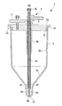
本実施形態に係る遠心分離容器1は、図1に示されるように、容器本体2と、該容器本体2の上部開口2aを閉塞する蓋体3と、該蓋体3に設けられた給排手段4と、前記蓋体2に設けられたフィルタ5とを備えている。
The
As shown in FIG. 1, the
容器本体2は、図2に示されるように、上部開口2aから延びる略円筒形状の第1の円筒内面2bと、該第1の円筒内面2bに滑らかに接続し、先端に向かって所定のテーパ角度で漸次先細になるテーパ内面2cと、該テーパ内面2cに滑らかに接続し、先端を閉塞された略円筒形状の第2の円筒内面2dとを備えている。第1の円筒内面2bおよび第2の円筒内面2dは、先端に向かって若干先細に形成されている。上部開口2aの半径方向外側には鍔部2eが設けられている。
As shown in FIG. 2, the
第2の円筒内面2dの軸方向長さは、細胞懸濁液Aを細胞層Bと上清Cとに分離したときに、細胞層Bと上清Cとの境界面Dが第2の円筒内面2dの軸方向の途中位置に形成される長さ寸法に設定されている。
The axial length of the second cylindrical
蓋体3は、容器本体2の上部開口2aに嵌合し、Oリング6によって上部開口2aを密閉するようになっている。また、蓋体3には、容器本体2の鍔部2eに係合して、蓋体3を容器本体2の上部開口2aに嵌合状態に維持するための係合突起3aが周方向に間隔をあけて複数設けられている。
The
給排手段4は、蓋体3の中央を厚さ方向に貫通する2重管状に形成され、蓋体3が容器本体2の上部開口2aを閉塞する位置に嵌合された状態で、その先端の開口部4aが第2の円筒内面2d先端の閉塞端2f近傍に配置される第1の管路4bと、その半径方向外方に同心に配置される第2の管路4cとを備えている。
第1の管路4bには、蓋体3の外側に配置される端部に、例えば、シリンジのような吸引手段を接続可能なポート4dが設けられている。図中、ポート4dはキャップ4eによって閉塞されている。このポート4dにシリンジを接続して吸引することにより、容器本体2の閉塞端2f近傍から内容物全てを吸引することができるようになっている。
The supply / discharge means 4 is formed in a double tubular shape penetrating the center of the
In the
第2の管路4cは、その先端において、第1の管路4bとの隙間が閉塞されているとともに、テーパ内面2cと第2の円筒内面2dとの境界線近傍の高さ位置において半径方向に貫通する貫通穴4fにより容器本体2内部の空間に開口している。第2の管路4cと第1の管路4bとの隙間には、蓋体3の外部において外部配管(図示略)が接続されるようになっている。
The
これにより、第1の配管4bと第2の配管4cとの間の円筒状の空間を介して、細胞懸濁液Aが容器本体2内に導入され、または、容器本体2の上清Cが吸引され、または、生理食塩水のような洗浄液が供給、排出されるようになっている。2重管状に形成された給排手段4は、蓋体3から軸方向に延びる筒状部3bによって支持されている。これにより、遠心分離容器1に遠心力が作用しても、給排手段4の位置が変動しないように保持され、第1の配管4bおよび第2の配管4cの先端の開口部4a,4fが位置決め状態に維持されるようになっている。
Thereby, the cell suspension A is introduced into the
フィルタ5は、外部からの外気Gを容器本体2に導入する際に、外気Gに含まれている塵埃や細菌等が容器本体2内に入らないように遮断する役割を有している。フィルタ5を介して外気Gを導入することにより、上清Cや細胞等の吸引時に容器本体2内部の空間が負圧になることを防止し、吸引動作をスムーズに行うことができるようになっている。
The
このように構成された本実施形態に係る遠心分離容器1の作用について以下に説明する。
本実施形態に係る遠心分離容器1を用いて細胞懸濁液Aから細胞を分離回収するには、容器本体2の上部開口2aを蓋体3によって密封した状態で、外部配管を介して第1の配管4bと第2の配管4cとの間の円筒状の空間から容器本体2内に細胞懸濁液Aを導入する。
The operation of the
In order to separate and recover cells from the cell suspension A using the
細胞懸濁液Aは、例えば、脂肪組織等の生体組織を消化液によって分解し、単離された細胞を消化液中に浮遊させたものである。
このようにして、図3に示されるように、容器本体2内に所定量の細胞懸濁液Aが貯留された状態で、図示しない遠心分離機により容器本体2の閉塞端2fが半径方向外側に配されるように回転させることにより、容器本体2内の細胞懸濁液Aに遠心力が作用し、比重の大きな細胞が閉塞端2fに向かって移動する。
The cell suspension A is obtained by, for example, decomposing a living tissue such as adipose tissue with a digestive fluid and suspending isolated cells in the digestive fluid.
In this way, as shown in FIG. 3, the
細胞は、移動の途中においては、テーパ内面2cを転がることにより、第2の円筒内面2dに向かって集められ、第2の円筒内面2dの閉塞端2fに堆積していく。そして、十分に遠心分離が進行すると、図4に示されるように、細胞層Bと上清Cとが明確に分離して、両者の間に境界面Dが形成される。
本実施形態においては、第2の円筒内面2dが、その軸方向の途中位置に境界面Dが形成されるような長さ寸法に形成されているので、図4に示されるように、境界面Dが形成され、第2の配管4cに設けた貫通穴4fが、境界面Dより上方の上清C内に開口するようになる。
In the middle of the movement, the cells are collected toward the second cylindrical
In the present embodiment, the second cylindrical
この状態で、第1の配管4bと第2の配管4cとの間の円筒状の空間を負圧に吸引すると、図5に示されるように貫通穴4fを介して容器本体2内の上清Cが吸引され、図6に示されるように、細胞層Bの上方に若干の上清Cが残るまで吸引される。
次いで、第1の配管4bと第2の配管4cとの間の円筒状の空間に洗浄液を供給し、容器本体2内に残った細胞層Bおよび若干の上清Cに混合することにより再懸濁する。そして、遠心分離、上清Cの吸引、洗浄液の供給・再懸濁を1回以上繰り返すことにより、細胞に付着している消化液が洗浄され、細胞懸濁液A内の消化酵素の濃度を低減することができる。
In this state, when the cylindrical space between the
Subsequently, the washing liquid is supplied to the cylindrical space between the
そして、十分に消化酵素の濃度が低減された状態で、分離された細胞層Bと若干の上清Cに対して少量の生理食塩水を供給して再懸濁することにより再懸濁液A′を調製し、図7に示されるように第1の配管4bの容器本体2外の端部に取り付けたシリンジ(図示略)によって吸引することにより、得られた再懸濁液A′を容器本体2内に残すことなくシリンジ内に吸引することができる。
Then, in a state in which the concentration of the digestive enzyme is sufficiently reduced, a small amount of physiological saline is supplied to the separated cell layer B and some of the supernatant C to resuspend the resuspension A. ′ And sucked by a syringe (not shown) attached to the end of the
この場合において、本実施形態に係る遠心分離容器1によれば、テーパ内面2cの先端に、十分に小さい口径を有する第2の円筒内面2dが設けられているので、上清Cから分離されて堆積した細胞層Bの上清Cとの境界面Dの面積を十分に小さく抑えることができる。また、上清Cを吸引する第2の配管4cに設けた貫通穴4fが、半径方向に貫通形成されているので、吸引される上清Cの流れが、境界面Dに直接影響を与えないように形成される。
In this case, according to the
その結果、上清Cが吸引される際の上清Cの流れによって、境界面Dから細胞が上清C内に舞い上がることを効果的に抑制することができ、上清Cとともに細胞が吸引・排出されてしまう不都合の発生を防止することができる。
すなわち、分離された細胞層Bから細胞の一部が排出されてしまう不都合を防止でき、細胞の収率を向上することができるという利点がある。
As a result, the flow of the supernatant C when the supernatant C is aspirated can effectively prevent cells from rising from the boundary surface D into the supernatant C. It is possible to prevent the occurrence of inconvenience that is discharged.
That is, there is an advantage that the inconvenience that a part of the cells is discharged from the separated cell layer B can be prevented, and the yield of the cells can be improved.
また、本実施形態に係る遠心分離容器1によれば、第2の円筒内面2dが略円筒形状を有しているので、異なる細胞懸濁液Aごとに、分離される細胞の細胞数が変動して、境界面Dの高さ位置が変動しても、境界面Dの面積の変動を極力抑えることができる。その結果、このような場合においても、境界面Dから細胞が上清C内に舞い上がることを効果的に防止することができる。
Moreover, according to the
また、本実施形態に係る遠心分離容器1によれば、上述したように、境界面Dの面積を抑制することにより境界面Dからの細胞の舞い上がりを防止するので、遠心分離時に作用させる遠心力を低減することができ、細胞に加わるダメージを低減して、細胞の健全性を維持することができるという利点がある。
Moreover, according to the
また、本実施形態に係る遠心分離容器1によれば、容器本体2の第1の円筒内面2bおよび第2の円筒内面2dが、いずれも先端に向かって若干先細となるような傾斜を有しているので、これを抜き勾配として使用し、樹脂射出成形のような方法によって、容易に製造することができる。
Moreover, according to the
なお、本実施形態においては、テーパ内面2cの先端に略円筒形状の第2の円筒内面2dを設けることとしたが、これに代えて、図8に示されるように、テーパ内面2cより十分に小さいテーパ角度を有する第2のテーパ内面2gを有することとしてもよい。
この場合、例えば、テーパ内面2cのテーパ角度を25°〜45°とし、第2のテーパ内面2gのテーパ角度を5°〜20°に設定することとすればよい。
In the present embodiment, the substantially cylindrical second cylindrical
In this case, for example, the taper angle of the taper
A 細胞懸濁液
B 細胞層
C 上清
D 境界面
1 遠心分離容器
2b 第1の円筒内面
2c テーパ内面(第1のテーパ内面)
2d 第2の円筒内面
2g 第2のテーパ内面
4a 開口部(細胞吸引口)
4f 貫通穴(上清吸引口)
A Cell suspension B Cell layer C Supernatant
2d 2nd cylindrical
4f Through hole (Supernatant suction port)
Claims (6)
略円筒形状を有する第1の円筒内面と、
該第1の円筒内面の先端に配置され、先端に向かって漸次先細になるテーパ内面と、
該テーパ内面の先端に配置され、先端を閉塞された略円筒形状を有し、前記細胞層と前記上清との境界面をその軸方向の途中位置に形成する長さ寸法を有する第2の円筒内面と、
前記境界面の上方において前記上清を吸引する上清吸引口とを備える遠心分離容器。 A centrifuge container that stores a cell suspension and separates the cell suspension into a cell layer and a supernatant by applying centrifugal force,
A first cylindrical inner surface having a substantially cylindrical shape;
A tapered inner surface disposed at the tip of the inner surface of the first cylinder and gradually tapering toward the tip;
A second cylinder having a substantially cylindrical shape disposed at the tip of the tapered inner surface and closed at the tip and having a length dimension that forms a boundary surface between the cell layer and the supernatant at an intermediate position in the axial direction. A cylindrical inner surface ;
A centrifuge container comprising a supernatant suction port for sucking the supernatant above the boundary surface .
略円筒形状を有する円筒内面と、
該円筒内面の先端に配置され、先端に向かって漸次先細になる第1のテーパ内面と、
該第1のテーパ内面の先端に配置され、閉塞された先端に向かって漸次先細に形成され、前記第1のテーパ内面よりも小さいテーパ角度を有し、前記細胞層と前記上清との境界面をその軸方向の途中位置に形成する長さ寸法を有する第2のテーパ内面と、
前記境界面の上方において前記上清を吸引する上清吸引口とを備える遠心分離容器。 A centrifuge container that stores a cell suspension and separates the cell suspension into a cell layer and a supernatant by applying centrifugal force,
A cylindrical inner surface having a substantially cylindrical shape;
A first tapered inner surface disposed at the tip of the cylindrical inner surface and gradually tapering toward the tip;
A boundary between the cell layer and the supernatant, which is disposed at the tip of the inner surface of the first taper, is gradually tapered toward the closed tip, has a smaller taper angle than the inner surface of the first taper. A second taper inner surface having a length dimension that forms the surface at an intermediate position in the axial direction ;
A centrifuge container comprising a supernatant suction port for sucking the supernatant above the boundary surface .
Priority Applications (1)
| Application Number | Priority Date | Filing Date | Title |
|---|---|---|---|
| JP2008032452A JP5078020B2 (en) | 2008-02-13 | 2008-02-13 | Centrifuge container |
Applications Claiming Priority (1)
| Application Number | Priority Date | Filing Date | Title |
|---|---|---|---|
| JP2008032452A JP5078020B2 (en) | 2008-02-13 | 2008-02-13 | Centrifuge container |
Publications (2)
| Publication Number | Publication Date |
|---|---|
| JP2009189282A JP2009189282A (en) | 2009-08-27 |
| JP5078020B2 true JP5078020B2 (en) | 2012-11-21 |
Family
ID=41071938
Family Applications (1)
| Application Number | Title | Priority Date | Filing Date |
|---|---|---|---|
| JP2008032452A Expired - Fee Related JP5078020B2 (en) | 2008-02-13 | 2008-02-13 | Centrifuge container |
Country Status (1)
| Country | Link |
|---|---|
| JP (1) | JP5078020B2 (en) |
Families Citing this family (23)
| Publication number | Priority date | Publication date | Assignee | Title |
|---|---|---|---|---|
| JP5090316B2 (en) * | 2008-11-12 | 2012-12-05 | オリンパス株式会社 | Centrifuge container |
| KR101679671B1 (en) * | 2009-10-27 | 2016-11-28 | 도병록 | System for extracting regenerative cells |
| KR101316573B1 (en) * | 2009-10-27 | 2013-10-15 | 도병록 | System and unit for extracting regenerative cells |
| JP2011125813A (en) * | 2009-12-18 | 2011-06-30 | National Cancer Center | Centrifugal separation container, adapter for retaining position of centrifugal separation container and centrifugal separation implement |
| US9206387B2 (en) | 2010-07-09 | 2015-12-08 | The Gid Group, Inc. | Method and apparatus for processing adipose tissue |
| US9296984B2 (en) | 2010-07-09 | 2016-03-29 | The Gid Group, Inc. | Tissue processing apparatus and method for processing adipose tissue |
| EP2590695A4 (en) | 2010-07-09 | 2017-09-06 | The Gid Group, Inc. | Apparatus and methods relating to collecting and processing human biological material containing adipose |
| WO2014039697A1 (en) | 2012-09-06 | 2014-03-13 | The Gid Group, Inc. | Tissue processing apparatus and method for processing adipose tissue |
| WO2013106655A1 (en) | 2012-01-11 | 2013-07-18 | The Gid Group, Inc. | Method for processing adipose tissue and processing apparatus |
| US9580678B2 (en) | 2013-06-21 | 2017-02-28 | The Regents Of The University Of California | Microfluidic tumor tissue dissociation device |
| EP3038629B1 (en) | 2013-09-05 | 2020-11-18 | GID BIO, Inc. | Method for processing adipose tissue |
| CA2938268A1 (en) * | 2014-01-31 | 2015-08-06 | Dsm Ip Assets B.V. | Adipose tissue processing centrifuge and methods of use |
| BR112016025266A2 (en) | 2014-05-02 | 2017-08-15 | Lifecell Corp | surgical instruments and adipose tissue transplantation method |
| JP2017035079A (en) * | 2015-08-11 | 2017-02-16 | 株式会社ジェイ・エム・エス | Microtube, cell housing recovery tool set, and cell recovery auxiliary tool |
| AU2016342012A1 (en) | 2015-10-21 | 2018-05-10 | Lifecell Corporation | Systems and methods for medical device control |
| MX2018004956A (en) * | 2015-10-21 | 2018-09-12 | Lifecell Corp | Systems and methods for tube management. |
| CA3008035A1 (en) | 2015-12-22 | 2017-06-29 | Lifecell Corporation | Syringe filling device for fat transfer |
| US10722540B1 (en) | 2016-02-01 | 2020-07-28 | The Regents Of The University Of California | Microfluidic device and method for shear stress-induced transformation of cells |
| WO2017214323A1 (en) | 2016-06-08 | 2017-12-14 | The Regents Of The University Of California | Method and device for processing tissues and cells |
| BR112019003871A2 (en) | 2016-08-30 | 2019-07-16 | Lifecell Corp | medical device control systems and methods |
| USD851777S1 (en) | 2017-01-30 | 2019-06-18 | Lifecell Corporation | Canister-type device for tissue processing |
| EP3655518A4 (en) | 2017-07-18 | 2021-07-14 | GID Bio, Inc. | Adipose tissue digestion system and tissue processing method |
| KR20210108048A (en) * | 2020-02-25 | 2021-09-02 | (주)시지바이오 | Centrifuging vessel |
Family Cites Families (5)
| Publication number | Priority date | Publication date | Assignee | Title |
|---|---|---|---|---|
| JPS5321986Y2 (en) * | 1974-05-25 | 1978-06-08 | ||
| US5491067A (en) * | 1993-07-15 | 1996-02-13 | Ortho Diagnostic Systems Inc. | Agglutination reaction and separation vessel |
| JPH08108096A (en) * | 1994-08-17 | 1996-04-30 | Toshiki Uchida | Vessel for centrifugal separation |
| JP3744298B2 (en) * | 1999-02-02 | 2006-02-08 | ニプロ株式会社 | Sperm cleaning and concentration tube and sperm cleaning and concentration method |
| JP2005238158A (en) * | 2004-02-27 | 2005-09-08 | Iwashiya Bio Science:Kk | Centrifugal pipe |
-
2008
- 2008-02-13 JP JP2008032452A patent/JP5078020B2/en not_active Expired - Fee Related
Also Published As
| Publication number | Publication date |
|---|---|
| JP2009189282A (en) | 2009-08-27 |
Similar Documents
| Publication | Publication Date | Title |
|---|---|---|
| JP5078020B2 (en) | Centrifuge container | |
| JP4399453B2 (en) | Method and apparatus for separating liquid components | |
| US9388377B2 (en) | Regenerative cell extraction unit and regenerative cell extraction system | |
| US10155083B2 (en) | Apheresis bowl with improved vibration characteristics | |
| JP2010043876A (en) | Centrifugal separation container | |
| WO2010035709A1 (en) | Centrifugal separation container | |
| CN1780583A (en) | Method and tool for filtrating specimen using specimen sampling container, and specimen sampling container | |
| US20110294203A1 (en) | Cell washing | |
| JP5090316B2 (en) | Centrifuge container | |
| EP1216099B1 (en) | Assembly comprising a centrifuge container and an adapter | |
| JP2010127708A (en) | Centrifugal separation vessel and centrifugal separation method | |
| JP2012044876A (en) | Centrifugal container | |
| JP2011004705A (en) | Cell separation device and cell separation method | |
| US10035118B2 (en) | Lipoaspirate stem cell separation system and methods thereof | |
| JP2012101138A (en) | Centrifugal separation vessel | |
| US8973213B2 (en) | Dust collection unit and vacuum cleaner with the same | |
| JP2010099616A (en) | Centrifugal separation vessel | |
| CN207227399U (en) | A kind of large volume urine DNA/RNA extraction systems | |
| IT9040130A1 (en) | SEPARATOR AND UNLOADER OF LIQUIDS AND SOLID PARTICLES, IN PARTICULAR FOR DENTAL SUCTION PLANTS | |
| JP2010104918A (en) | Separating equipment | |
| KR101588754B1 (en) | Centrifuge tube | |
| CN216296364U (en) | A centrifuging tube for cosmetics detect | |
| JP2010063440A (en) | Centrifugation vessel | |
| JP2007029889A (en) | Centrifugal container and centrifuge | |
| KR102583939B1 (en) | Device that Collects Garbage Using Bag |
Legal Events
| Date | Code | Title | Description |
|---|---|---|---|
| A621 | Written request for application examination |
Free format text: JAPANESE INTERMEDIATE CODE: A621 Effective date: 20110126 |
|
| A977 | Report on retrieval |
Free format text: JAPANESE INTERMEDIATE CODE: A971007 Effective date: 20120216 |
|
| A131 | Notification of reasons for refusal |
Free format text: JAPANESE INTERMEDIATE CODE: A131 Effective date: 20120321 |
|
| A521 | Written amendment |
Free format text: JAPANESE INTERMEDIATE CODE: A523 Effective date: 20120621 |
|
| TRDD | Decision of grant or rejection written | ||
| A01 | Written decision to grant a patent or to grant a registration (utility model) |
Free format text: JAPANESE INTERMEDIATE CODE: A01 Effective date: 20120807 |
|
| A01 | Written decision to grant a patent or to grant a registration (utility model) |
Free format text: JAPANESE INTERMEDIATE CODE: A01 |
|
| A61 | First payment of annual fees (during grant procedure) |
Free format text: JAPANESE INTERMEDIATE CODE: A61 Effective date: 20120823 |
|
| FPAY | Renewal fee payment (prs date is renewal date of database) |
Free format text: PAYMENT UNTIL: 20150907 Year of fee payment: 3 |
|
| R150 | Certificate of patent (=grant) or registration of utility model |
Free format text: JAPANESE INTERMEDIATE CODE: R150 |
|
| LAPS | Cancellation because of no payment of annual fees |