EP3365430B1 - Systems and methods for tube management - Google Patents
Systems and methods for tube management Download PDFInfo
- Publication number
- EP3365430B1 EP3365430B1 EP16791208.8A EP16791208A EP3365430B1 EP 3365430 B1 EP3365430 B1 EP 3365430B1 EP 16791208 A EP16791208 A EP 16791208A EP 3365430 B1 EP3365430 B1 EP 3365430B1
- Authority
- EP
- European Patent Office
- Prior art keywords
- tube
- flow
- tubes
- tissue
- position switch
- Prior art date
- Legal status (The legal status is an assumption and is not a legal conclusion. Google has not performed a legal analysis and makes no representation as to the accuracy of the status listed.)
- Active
Links
Images


Classifications
-
- A—HUMAN NECESSITIES
- A61—MEDICAL OR VETERINARY SCIENCE; HYGIENE
- A61M—DEVICES FOR INTRODUCING MEDIA INTO, OR ONTO, THE BODY; DEVICES FOR TRANSDUCING BODY MEDIA OR FOR TAKING MEDIA FROM THE BODY; DEVICES FOR PRODUCING OR ENDING SLEEP OR STUPOR
- A61M1/00—Suction or pumping devices for medical purposes; Devices for carrying-off, for treatment of, or for carrying-over, body-liquids; Drainage systems
- A61M1/60—Containers for suction drainage, adapted to be used with an external suction source
-
- A—HUMAN NECESSITIES
- A61—MEDICAL OR VETERINARY SCIENCE; HYGIENE
- A61M—DEVICES FOR INTRODUCING MEDIA INTO, OR ONTO, THE BODY; DEVICES FOR TRANSDUCING BODY MEDIA OR FOR TAKING MEDIA FROM THE BODY; DEVICES FOR PRODUCING OR ENDING SLEEP OR STUPOR
- A61M1/00—Suction or pumping devices for medical purposes; Devices for carrying-off, for treatment of, or for carrying-over, body-liquids; Drainage systems
- A61M1/71—Suction drainage systems
- A61M1/74—Suction control
- A61M1/743—Suction control by changing the cross-section of the line, e.g. flow regulating valves
-
- A—HUMAN NECESSITIES
- A61—MEDICAL OR VETERINARY SCIENCE; HYGIENE
- A61M—DEVICES FOR INTRODUCING MEDIA INTO, OR ONTO, THE BODY; DEVICES FOR TRANSDUCING BODY MEDIA OR FOR TAKING MEDIA FROM THE BODY; DEVICES FOR PRODUCING OR ENDING SLEEP OR STUPOR
- A61M1/00—Suction or pumping devices for medical purposes; Devices for carrying-off, for treatment of, or for carrying-over, body-liquids; Drainage systems
- A61M1/71—Suction drainage systems
- A61M1/77—Suction-irrigation systems
-
- A—HUMAN NECESSITIES
- A61—MEDICAL OR VETERINARY SCIENCE; HYGIENE
- A61M—DEVICES FOR INTRODUCING MEDIA INTO, OR ONTO, THE BODY; DEVICES FOR TRANSDUCING BODY MEDIA OR FOR TAKING MEDIA FROM THE BODY; DEVICES FOR PRODUCING OR ENDING SLEEP OR STUPOR
- A61M1/00—Suction or pumping devices for medical purposes; Devices for carrying-off, for treatment of, or for carrying-over, body-liquids; Drainage systems
- A61M1/89—Suction aspects of liposuction
- A61M1/892—Suction aspects of liposuction with treatment of the collected fat
-
- A—HUMAN NECESSITIES
- A61—MEDICAL OR VETERINARY SCIENCE; HYGIENE
- A61M—DEVICES FOR INTRODUCING MEDIA INTO, OR ONTO, THE BODY; DEVICES FOR TRANSDUCING BODY MEDIA OR FOR TAKING MEDIA FROM THE BODY; DEVICES FOR PRODUCING OR ENDING SLEEP OR STUPOR
- A61M39/00—Tubes, tube connectors, tube couplings, valves, access sites or the like, specially adapted for medical use
- A61M39/10—Tube connectors; Tube couplings
- A61M39/105—Multi-channel connectors or couplings, e.g. for connecting multi-lumen tubes
-
- A—HUMAN NECESSITIES
- A61—MEDICAL OR VETERINARY SCIENCE; HYGIENE
- A61M—DEVICES FOR INTRODUCING MEDIA INTO, OR ONTO, THE BODY; DEVICES FOR TRANSDUCING BODY MEDIA OR FOR TAKING MEDIA FROM THE BODY; DEVICES FOR PRODUCING OR ENDING SLEEP OR STUPOR
- A61M39/00—Tubes, tube connectors, tube couplings, valves, access sites or the like, specially adapted for medical use
- A61M39/22—Valves or arrangement of valves
- A61M39/28—Clamping means for squeezing flexible tubes, e.g. roller clamps
-
- A—HUMAN NECESSITIES
- A61—MEDICAL OR VETERINARY SCIENCE; HYGIENE
- A61B—DIAGNOSIS; SURGERY; IDENTIFICATION
- A61B17/00—Surgical instruments, devices or methods, e.g. tourniquets
- A61B2017/00743—Type of operation; Specification of treatment sites
- A61B2017/00792—Plastic surgery
-
- A—HUMAN NECESSITIES
- A61—MEDICAL OR VETERINARY SCIENCE; HYGIENE
- A61B—DIAGNOSIS; SURGERY; IDENTIFICATION
- A61B18/00—Surgical instruments, devices or methods for transferring non-mechanical forms of energy to or from the body
- A61B2018/00315—Surgical instruments, devices or methods for transferring non-mechanical forms of energy to or from the body for treatment of particular body parts
- A61B2018/00452—Skin
- A61B2018/00458—Deeper parts of the skin, e.g. treatment of vascular disorders or port wine stains
- A61B2018/00464—Subcutaneous fat, e.g. liposuction, lipolysis
-
- A—HUMAN NECESSITIES
- A61—MEDICAL OR VETERINARY SCIENCE; HYGIENE
- A61M—DEVICES FOR INTRODUCING MEDIA INTO, OR ONTO, THE BODY; DEVICES FOR TRANSDUCING BODY MEDIA OR FOR TAKING MEDIA FROM THE BODY; DEVICES FOR PRODUCING OR ENDING SLEEP OR STUPOR
- A61M1/00—Suction or pumping devices for medical purposes; Devices for carrying-off, for treatment of, or for carrying-over, body-liquids; Drainage systems
- A61M1/71—Suction drainage systems
- A61M1/79—Filters for solid matter
-
- A—HUMAN NECESSITIES
- A61—MEDICAL OR VETERINARY SCIENCE; HYGIENE
- A61M—DEVICES FOR INTRODUCING MEDIA INTO, OR ONTO, THE BODY; DEVICES FOR TRANSDUCING BODY MEDIA OR FOR TAKING MEDIA FROM THE BODY; DEVICES FOR PRODUCING OR ENDING SLEEP OR STUPOR
- A61M1/00—Suction or pumping devices for medical purposes; Devices for carrying-off, for treatment of, or for carrying-over, body-liquids; Drainage systems
- A61M1/89—Suction aspects of liposuction
- A61M1/895—Suction aspects of liposuction with means for reinjection of collected fat
-
- A—HUMAN NECESSITIES
- A61—MEDICAL OR VETERINARY SCIENCE; HYGIENE
- A61M—DEVICES FOR INTRODUCING MEDIA INTO, OR ONTO, THE BODY; DEVICES FOR TRANSDUCING BODY MEDIA OR FOR TAKING MEDIA FROM THE BODY; DEVICES FOR PRODUCING OR ENDING SLEEP OR STUPOR
- A61M2202/00—Special media to be introduced, removed or treated
- A61M2202/08—Lipoids
-
- C—CHEMISTRY; METALLURGY
- C12—BIOCHEMISTRY; BEER; SPIRITS; WINE; VINEGAR; MICROBIOLOGY; ENZYMOLOGY; MUTATION OR GENETIC ENGINEERING
- C12M—APPARATUS FOR ENZYMOLOGY OR MICROBIOLOGY; APPARATUS FOR CULTURING MICROORGANISMS FOR PRODUCING BIOMASS, FOR GROWING CELLS OR FOR OBTAINING FERMENTATION OR METABOLIC PRODUCTS, i.e. BIOREACTORS OR FERMENTERS
- C12M45/00—Means for pre-treatment of biological substances
- C12M45/02—Means for pre-treatment of biological substances by mechanical forces; Stirring; Trituration; Comminuting
Definitions
- Some surgical procedures require use of tubes, hoses, or other conduits to transfer fluids, gases, and/or tissue products between a patient and a treatment system or device, or among systems and devices. Some surgical procedures are multi-step processes requiring connection and disconnection of hoses from input and output ports. For example, using some adipose tissue transfer systems, surgical personnel may need to perform over one hundred combined user actions and decisions. Some of these user actions involve enabling and disabling a vacuum source or adding or removing tissue or washing solutions to a tissue storage and treatment container.
- a tissue treatment system in an embodiment of the present invention, includes a container and a tube management device.
- the container includes an exterior wall surrounding an interior volume for holding tissue and a filter for processing tissue.
- the tube management device includes a tube restrictor plate having a plurality of tube through-holes and a tube stabilizer plate having a plurality of tube through-holes.
- a plurality of flow-restricting devices is disposed on the tube restrictor plate adjacent to the plurality of tube through-holes.
- the tube management device further includes a multi-position switch. A plurality of tubes pass through the tube through-holes.
- setting the multi-position switch to a first position causes the plurality of flow-restricting devices to restrict the flow in a first subset of the plurality of tubes to transfer tissue from a patient to the interior volume
- setting the multi-position switch to a second position causes the plurality of flow-restricting devices to restrict the flow in a second subset of the plurality of tubes to allow processing of the tissue in the interior volume
- setting the multi-position switch to a third position causes the plurality of flow-restricting devices to restrict the flow in a third subset of the plurality of tubes to allow transfer of the tissue out of the interior volume.
- US3791524 describes a tissue collector designed especially for obtaining a fetus in a sterile condition.
- WO2013/090579 describes a cassette for use with a medical waste collection system.
- US8887770 describes methods and systems for filling a container with material to a desired level.
- a method of managing surgical conduits provides a plurality of tubes and a plurality of flow-restricting devices within a body, each of the flow-restricting devices proximal to at least one of the plurality of tubes.
- the method also provides a multi-position switch wherein flow in a first subset of the plurality of tubes is restricted by the plurality of flow-restricting devices when the multi-position switch is in a first position and flow in a second subset of the plurality of tubes different than the first subset is restricted by the plurality of flow-restricting devices when the multi-position switch is in a second position.
- the method also switches from the first position of the multi-position switch to the second position of the multi-position switch.
- a tube management device in an embodiment of the present invention, includes a tube restrictor plate having a plurality of tube through-holes and a tube stabilizer plate having a plurality of tube through-holes.
- a plurality of flow-restricting devices is disposed on the tube restrictor plate adjacent to the plurality of tube through-holes.
- the tube management device also includes a multi-position switch and a plurality of tubes that pass through the pluralities of tube through-holes.
- Setting the multi-position switch of the tube management device to a first position causes the plurality of flow-restricting devices to restrict the flow in a first subset of the plurality of tubes
- setting the multi-position switch to a second position causes the plurality of flow-restricting devices to restrict the flow in a second subset of the plurality of tubes
- setting the multi-position switch to a third position causes the plurality of flow-restricting devices to restrict the flow in a third subset of the plurality of tubes.
- adipose tissue refers to adipose tissue obtained by any means including, for example, liposuction and/or tumescent liposuction.
- the adipose tissue may be substantially intact or may be altered by, for example, washing with saline, antimicrobials, detergents, or other agents; the addition of therapeutic agents such an analgesics, antimicrobials, and anti-inflammatories; the removal of some cells or acellular components; or disruption or alteration by the collection process itself including, for example, during liposuction or tumescent liposuction.
- the adipose tissue can be autologous tissue, allogeneic tissue, or xenogenic tissue (e.g., porcine tissue).
- adipose tissue transfer and processing can require over one hundred combined user actions and decisions, including enabling and disabling vacuum sources or adding or removing tissue or washing solutions to a tissue storage and treatment container.
- the maintenance and verification of tube connections during a medical procedure can be non-trivial, especially when the procedure has a time-sensitive component.
- Various human and animal tissues can be used to produce products for treating patients.
- various tissue products have been produced for regeneration, repair, augmentation, reinforcement, and/or treatment of human tissues that have been damaged or lost due to various diseases and/or structural damage (e.g., from trauma, surgery, atrophy, and/or long-term wear and degeneration).
- Fat grafting including autologous fat grafting, can be useful for a variety of clinical applications including facial fillers, breast augmentation, buttock augmentation/sculpting, augmentation of other tissue sites, correction of lumpectomy defects, cranial-facial defect correction, and correction of lipoplasty defects (divots).
- tissue cleaning and processing must be performed.
- the process of grafting typically involves steps such as removal of tissue from a patient with a syringe or cannula. This tissue is pulled into a tissue processing container where unwanted components of the tissue can be separated and/or the tissue can be cleaned using various solutions.
- a typical system might include meshes for filtration and separation, cranks connected to mixing blades, and several input and output ports.
- vacuum devices help move the tissue from location to location. However, it is desirable to disconnect the vacuum pressure during processing steps.
- the tissue-carrying tubes that are not in use during any given step should be blocked to maintain the sterility of the system.
- the tissue treatment system 100 can include a container having an exterior wall 110 surrounding an interior volume.
- the interior of the container can also contain filters, mixing blades, hoses, and other components to enable washing and conditioning of tissue.
- the system 100 can include a tube management device 101 to facilitate operation of the system 100. Tubes can pass from the exterior of the system 100 to the interior through ports 102 of the tube management device 101, and tube restrictor devices (discussed below) within the tube management device 101 can control which tubes are open and which are blocked for a given system configuration.
- the system configuration is determined by the setting of a multi-position switch 103.
- the system 100 can be provided with a carry handle for convenient handling by a user.
- tube As used herein, the terms “tube,” “hose,” “conduit,” or similar language will be used interchangeably and will be understood to refer to any passageway having a lumen configured to allow passage or fluids, gases, and/or tissue products therethrough.
- the tube management device 101 may include ports 102a, 102b, 102c and a multi-position switch 103. Tubes can pass through the ports 102a, 102b, 102c and then through a tube restrictor plate 104 and a tube stabilizer plate 107 before passing out of the device 101. Based on the position of the multi-position switch 103, restrictor elements 105 on the tube restrictor plate 104 can allow or obstruct flow through each of the tubes.
- the contents of the tube management device 101 can be contained within an exterior wall 108 that forms a body. In alternate embodiments, the components of the tube management device 101 can be attached directly to the structure of the container 110.
- the ports 102a, 102b, 102c can have a variety of configurations.
- the ports 102a, 102b, 102c may be straight-walled or barbed; threaded or unthreaded; and have no fittings, luer fittings, swaged fittings, or any other type of connector suitable for a specific application.
- the ports 102a, 102b, 102c are depicted as extending out from the body of the tube management device 101, the ports may also be threaded or unthreaded holes or recesses or may extend inward from the surface into the body of the device 101. Although only three ports are depicted in FIG.
- any number of ports can be chosen to match the number of tubes needed in a particular application.
- Substances including, but not limited to, gases, liquids, chemical solutions, and biological tissues can flow into or out from the ports 102a, 102b, 102c depending upon the position of the multi-position switch and the requirements of any particular step of the medical procedure.
- the position of the multi-position switch 103 can be used to switch among different device configurations.
- the multi-position switch 103 is a rotating body or knob and the rotational angle of the body determines the switch state.
- the multi-position switch 103 may be any mechanical or electronic switch (including rotational or linear throw switches) that, through appropriate linkages, can alter the state of openness of tubes passing through the device.
- the multi-position switch 103 can include non-slip grips or similar features to facilitate easier operation by a user, in particular by a user wearing surgical gloves.
- the positions of the multi-position switch 103 may correspond to steps in a procedure.
- the steps in a procedure might include liposuction/tissue extraction, hold and mix, irrigation, and vacuum/clear steps.
- the tube restrictor plate 104 can block or allow flow through tubes that pass through the tube through-holes of the plate through the use of flow-restricting devices.
- the tube restrictor plate 104 may be provided with flow-restricting devices 105 in the form of contoured radial slots.
- the slots 105 can have a slot width that varies according to the desired action of the slot upon a tube for each angular position of the tube restrictor plate 104.
- each slot 105 may include two slot widths that correspond to unrestricted flow in a tube and complete blockage of flow in a tube.
- each slot may have a range of widths corresponding to different levels of flow restriction.
- a tube restrictor plate 104 is shown overlaid upon a tube stabilizer plate 107 with slots 105a, 105b, 105c indicated.
- the example embodiment of a tube restrictor plate 104 shown in FIG. 3 illustrates tube through-holes in the form of contoured radial slots 105a, 105b, 105c suitable for a tube management device 101 having a multi-position switch 103 with three positions.
- the contoured radial slots 105a, 105b, 105c of the tube restrictor plate 104 are overlaid in this top view on the tube through-holes 115a, 115b, 115c of the tube stabilizer plate 107.
- the position of tube restrictor plate 104 with respect to tube stabilizer plate 107 places slots 105a, 105b, 105c in the first position over tube through-holes 115a, 115b, 115c.
- Activation of the multi-position switch can cause the tube restrictor plate 104 to rotate in the direction shown by the arrow while the tube stabilizer plate 107 stays in place.
- the radial slots can advance to the second or third position as needed.
- the system 100 can be provided with a plurality of tube restrictor plates 104 having different arrangements of slots 105a, 105b, 105c intended for different procedures having different steps.
- the user may choose one of the plurality of tube restrictor plates 104 to place within the body 108 of the device 101 depending upon the application.
- the tube restrictor plate 104 may have locating features 106 that can interlock with the multi-position switch 103.
- the locating features 106 can help the user align the tube restrictor plate with the multi-position switch 103 and within the tube management device 101 so that the contoured radial slots 105a, 105b, 105c are properly in-line with their respective ports 102a, 102b, 102c.
- the locating features 106 can match with complementary features on the multi-position switch so that the switch's position reflects the proper tubing state within the tube management device 101.
- the locating features 106 can fix the multi-position switch 103 to the tube restrictor plate 104 such that they move in concert when the switch is rotated.
- the tube management device 101 can have a tube stabilizer plate 107.
- the tube stabilizer plate 107 may have tube through-holes 115 to allow tubes to pass therethrough.
- the diameter of each of the tube through-holes 115 in the tube stabilizer plate 107 may be equal or approximately equal to the outer diameter of the corresponding tube that passes through the hole 115 to provide a secure fit around the outside of each tube without compression.
- the tube stabilizer plate 107 can hold the tube in position so that activation or movement of the tube restrictor plate 104 cannot twist, reorient, or move the tubes.
- the system 100 can be used to operate surgical systems, such as adipose tissue transfer systems.
- an exemplary decision matrix 400 for an adipose tissue transfer process is shown in FIG. 4 .
- the decision matrix may be used to determine the open/closed status of any tubes in the system during any steps of an adipose transfer procedure.
- a tissue treatment system 100 similar to that shown in FIG. 1 can have 4 tube inputs that are either open or blocked during a given step of a medical procedure.
- the tube to the liposuction cannula and the vacuum tube may be open while the irrigation tube and vent tube are closed.
- a hold and mix or washing 404 step all 4 inputs can be blocked.
- the tube to the liposuction cannula and the vacuum tube may be closed while the irrigation tube and the vent tube can be open.
- a vacuum/clear 408 step the tube to the liposuction cannula and the irrigation tube may be closed while the vacuum tube and the vent tube can be open.
- the tube management device 501 can include ports 502 and a multi-position switch 503. Tubes can pass from the ports 502 through a tube restrictor plate 504 and a tube stabilizer plate 507 before passing out of the device 501. Based on the position of the multi-position switch, restrictor elements 505 on the tube restrictor plate 504 can allow or obstruct flow through each of the tubes.
- the contents of the tube management device 501 can be contained within an exterior wall 508 that forms a body.
- the ports can have a variety of configurations.
- the ports 502 may be straight-walled or barbed; threaded or unthreaded; and have no fittings, luer fittings, swaged fittings, or any other type of connector demanded by application-specific requirements.
- ports 502 are depicted in this embodiment as extending out from the body of the tube management device 501, the ports may also be threaded or unthreaded recesses or holes or may extend inward from the device surface into the body of the device 501.
- any number of ports can be chosen to match the number of tubes needed in a particular application.
- Substances including, but not limited to, gases, liquids, chemical solutions, and biological tissues can flow into or out from the ports 502 depending upon the position of the multi-position switch and the requirements of any particular step of the surgical procedure.
- the positions of the multi-position switch 503 can be used to switch among different device configurations.
- the multi-position switch 503 is a rotating body or knob and the rotational angle of the body determines the switch state.
- the multi-position switch 503 may be any mechanical or electronic switch (including rotational or linear throw switches) that, through appropriate linkages, can alter the state of openness of tubes passing through the device.
- the multi-position switch 503 can include non-slip grips or similar features to facilitate easier operation by a user, in particular by a user wearing surgical gloves.
- the positions of the multi-position switch 503 may correspond to steps in a procedure.
- the steps in a procedure might include liposuction/tissue extraction, hold and mix, irrigation, and vacuum/clear steps.
- the tube restrictor plate 504 can block or allow flow through the tubes that pass through the tube through-holes 516 of the plate through the use of flow-restricting devices.
- the tube restrictor plate 504 may include an external ring 504a that is rotatably engaged with a central portion 504b. Tubes can pass through the tube restrictor plate 504 through tube through-holes 516 adjacent to flow-restricting devices.
- the tube restrictor plate 504 may be provided with flow-restricting devices in the form of a contoured central hub 512 on the central portion 504b and sliding blocks 505 that force the tubes against the hub 512 via the integrated springs 514 attached to the external ring 504a.
- the sliding blocks 505 may be shaped as flat plates, cylinders, ovals, spheres, ovoid configuration, or any other shape that meets application-specific requirements.
- the contoured central hub 512 may have an equal number of recesses to the number of ports 502, and each tube may pass through a tube through-hole 516 adjacent to a recess of the contoured central hub.
- the force of the spring may extend the sliding block and force it against a tube.
- the central portion 504b of the tube restrictor plate 504 may be fixedly attached to the tube stabilizer plate 507. As the multi-position switch 503 changes from one position to another, the external ring 504a of the tube restriction plate 504 may rotate while the central portion 504b containing the contoured central hub 512 does not rotate relative to the tube stabilizer plate 507.
- the external ring 504a may be provided with a one-way ratcheting mechanism 509.
- the teeth of the ratcheting mechanism can engage with a pawl 511 positioned on the central portion 504b of the tube restriction plate 504 such that rotation of the external ring 504a is allowed in one direction but prevented in the opposite direction.
- the pawl 511 is depicted as being located on the central portion 504b in this embodiment, it will be apparent to those of ordinary skill in the art that the pawl could be attached at other points throughout the tube management device 501 such as the interior of the multi-position switch 503 or the tube stabilizer plate 507.
- the tube management device 501 can also include a tube stabilizer plate 507.
- the tube stabilizer plate 507 may have tube through-holes 515 to allow tubes to pass through.
- the diameter of each of the tube through-holes 515 in the tube stabilizer plate 507 may be equal to the outer diameter of the corresponding tube that passes through the hole to provide a secure fit around the outside of each tube without compression.
- the tube stabilizer plate 507 can hold the tube in position so that activation or movement of the tube restrictor plate 504 cannot twist, reorient, or move the tubes.
- the tube management device 601 can include ports 602 and a multi-position switch 603.
- the device 601 can include a tube stabilizer plate 607 and a tube restrictor plate 604 containing flow restriction devices.
- the components of the device 601 can be enclosed within a body 608.
- the ports 602 are the connection between the tube management device 601 and the exterior world.
- the ports 602 may be straight-walled or barbed; threaded or unthreaded; and have no fittings, luer fittings, swaged fittings, or any other type of connector demanded by application-specific requirements.
- the ports 602 are depicted in this embodiment as extending out from the body of the tube management device 601, the ports may also be threaded or unthreaded holes or may extend inward from the device surface into the body of the device 601.
- FIG. 6 it will be evident to one of ordinary skill in the art that any number of ports 602 can be chosen to match the number of tubes needed in a particular application.
- Fluids including, but not limited to, gases, liquids, chemical solutions, and biological tissues can flow into or out from the ports 602 depending upon the position of the multi-position switch and the requirements of any particular step of the medical procedure.
- the positions of the multi-position switch 603 can be used to switch among different device configurations.
- the multi-position switch 603 is a rotating body or knob and the rotational angle of the body determines the switch state.
- the multi-position switch 603 may be any mechanical or electronic switch (including rotational or linear throw switches) that, through appropriate linkages, can alter the state of openness of tubes passing through the device.
- the multi-position switch 603 can include non-slip grips or similar features to facilitate easier operation by a user, in particular by a user wearing surgical gloves.
- the positions of the multi-position switch 603 may correspond to steps in a procedure.
- the steps in a procedure might include liposuction/tissue extraction, hold and mix, irrigation, and vacuum/clear steps.
- the tube restrictor plate 604 may include an external ring 604a that is rotatably engaged with a central portion 604b. Tubes may pass through tube through-holes 616 adjacent to flow-restricting devices.
- the tube restrictor plate 604 may be provided with flow-restricting devices in the form of a contoured central hub 612 on the central portion 604b and sliding blocks 605 that force the tubes against the hub 612 via the integrated springs 614 attached to the external ring 604a.
- the sliding blocks 605 may be shaped as flat plates, cylinders, ovals, spheres, eggs, or any other shape that meets application-specific requirements.
- the contoured central hub 612 may have an equal number of recesses to the number of ports 602, and each tube may pass through a tube through-hole 616 adjacent to a recess of the contoured central hub.
- the force of the spring may extend the sliding block and force it against a tube.
- the external ring 604a of the tube restriction plate 604 may rotate while the central portion 604b containing the contoured central hub 612 does not rotate relative to the tube stabilizer plate 607.
- the sliding blocks 605 and integrated springs 614 can be placed at different radial depths using spacers 604c.
- the tube management device 601 can have a tube stabilizer plate 607 in some embodiments.
- the tube stabilizer plate 607 may have tube through-holes 615 to allow tubes to pass through.
- the diameter of each of the tube through-holes 615 in the tube stabilizer plate 607 may be equal to the outer diameter of the corresponding tube that passes through the hole to provide a secure fit around the outside of each tube without compression.
- the tube stabilizer plate 607 can hold the tube in position so that activation or movement of the tube restrictor plate 604 cannot twist, reorient, or move the tubes.
- FIG. 7 A top view of the tube restrictor plate 604 overlaid on tube stabilizer plate 607 of the embodiment of FIG. 6 is shown in FIG. 7 .
- the tube restrictor plate 604 can have slots 613 to allow the tubes to change position with respect to the contoured central hub 612 of the central portion 604b and the associated flow-restricting devices. In this way, a single embodiment of the tube restrictor plate 604 can be used in more than one configuration.
- the tube passes near a recess of the contoured central hub 612 and can be closed by sliding blocks 605 attached to spacers 604c extending from the external ring 604a.
- the tube When a tube is in an "out” position, the tube passes near an extended portion of the contoured central hub 612. In this position, the tube can be closed by sliding blocks 505 that are attached by integrated springs 614 directly to the external ring 604a. In a preferred embodiment, sliding blocks 605 attached directly to the external ring 604a without spacers 604c cannot reach tubes adjacent to recesses of the contoured central hub 612.
- the external ring 604a may be provided with a one-way ratcheting mechanism 609.
- the teeth of the ratcheting mechanism can engage with a pawl 611 positioned on the central portion 604b of the tube restriction plate 604 such that rotation of the external ring 604a is allowed in one direction but prevented in the opposite direction.
- the pawl 611 is depicted as being located on the central portion 604b in this embodiment, it will be apparent to those of ordinary skill in the art that the pawl could be attached at other points throughout the tube management device 601 such as the interior of the multi-position switch 603 or the tube stabilizer plate 607.
- a method of managing surgical conduits is also envisioned by the inventors.
- the method includes providing several tubes and several flow-restricting devices within a body where each of the flow-restricting devices is proximal to at least one of the tubes and providing a multi-position switch wherein the flow in a first subset of the tubes is restricted by the flow-restricting devices when the switch is in a first position and flow in a second subset of tubes different than the first subset is restricted by the flow-restricting devices when the switch is in a second position.
- the method concludes by switching from the first position of the multi-position switch to the second position.
- the step of providing several tubes and several flow-restricting devices within a body where each of the flow-restricting devices is proximal to at least one of the tubes may include, but is not limited to, passing tubes through ports 102 and past flow-restricting devices 105 in a tube management device 101 as described above in connection with FIGS. 1-3 .
- the step of providing a multi-position switch wherein the flow in a first subset of the tubes is restricted by the flow-restricting devices when the switch is in a first position and flow in a second subset of tubes different than the first subset is restricted by the flow-restricting devices when the switch is in a second position may include, but is not limited to, providing a multi-position switch 103 in a tube management device 101 as described above in connection with FIGS. 1-3 .
- the step of switching from the first position of the multi-position switch to the second position may include, but is not limited to, switching a multi-position switch 103 from a first position to a second position as described above in connection with FIGS. 1 and 2 .
- FIG. 8 An exploded view of an alternative embodiment of a tube management device 801 is shown in FIG. 8 .
- the tube management device 801 may include ports 802a, 802b, 802c and a multi-position switch 803. Tubes 812 pass through the ports 802a, 802b, 802c and then through a tube restrictor plate 804 and a tube stabilizer plate 807 before passing out of the device 801. Based on the position of the multi-position switch 803, restrictor elements 805 on the tube restrictor plate 804 can allow or obstruct flow through each of the tubes 812.
- the contents of the tube management device 801 can be contained within an exterior wall 808 that forms a body.
- the ports 802a, 802b, 802c can have a variety of configurations as described previously with respect to FIG. 2 .
- the ports 802a, 802b, 802c may be straight-walled or barbed; threaded or unthreaded; and have no fittings, luer fittings, swaged fittings, or any other type of connector suitable for a specific application.
- the ports 802a, 802b, 802c are depicted as extending out from the body of the tube management device 801, the ports may also be threaded or unthreaded holes or recesses or may extend inward from the surface into the body of the device 801. Although only three ports are depicted in FIG.
- any number of ports can be chosen to match the number of tubes 812 needed in a particular application.
- Substances including, but not limited to, gases, liquids, chemical solutions, and biological tissues can flow into or out of tubes 812 passing through the ports 802a, 802b, 802c depending upon the position of the multi-position switch and the requirements of any particular step of a medical procedure.
- the position of the multi-position switch 803 can be used to switch among different device configurations.
- the multi-position switch 803 is a rotating body or knob, and the rotational angle of the body determines the switch state.
- the multi-position switch 803 may be any mechanical or electronic switch (including rotational or linear throw switches) that, through appropriate linkages, can alter the state of openness of the tubes 812.
- the multi-position switch 803 can include non-slip grips or similar features to facilitate easier operation by a user, in particular by a user wearing surgical gloves.
- the positions of the multi-position switch 803 may correspond to steps in a procedure.
- the steps in a procedure might include liposuction/tissue extraction, hold and mix, irrigation, and vacuum/clear steps.
- the tube restrictor plate 804 can block or allow flow through the tubes 812 as they pass through the plate through the use of flow-restricting devices. Similar to the embodiments depicted in FIGS. 2 and 3 , the tube restrictor plate 804 may be provided with both flow-restricting devices and tube through-holes in the form of contoured radial slots 805. In alternative embodiments, the flow-restricting devices can be similar to those described above with reference to the embodiments of FIGS. 5 and 6 .
- the slots 805 can have a slot width that varies according to the desired action of the slot upon a tube 812 for each angular position of the tube restrictor plate 804. For example, each slot 805 may include two slot widths that correspond to unrestricted flow in a tube 812 and complete blockage of flow in a tube 812. Alternatively, each slot may have a range of widths corresponding to different levels of flow restriction.
- the tube restrictor plate 804 may have locating features 806 that can interlock with the multi-position switch 803.
- the locating features 806 can help the user align the tube restrictor plate 804 with the multi-position switch 803 and within the tube management device 801 so that the contoured radial slots 805 are properly in-line with their respective ports 802a, 802b, 802c.
- the locating features 806 can match with complementary features on the multi-position switch so that the switch's position reflects the proper tubing state within the tube management device 801.
- the locating features 806 can fix the multi-position switch 803 to the tube restrictor plate 804 such that they move in concert when the switch is rotated.
- the tube management device 801 can have a tube stabilizer plate 807.
- the tube stabilizer plate 807 may have tube through-holes 815 to allow tubes to pass therethrough.
- the diameter of each of the tube through-holes 815 in the tube stabilizer plate 807 may be equal or approximately equal to the outer diameter of the corresponding tube that passes through the hole to provide a secure fit around the outside of each tube without compression.
- the tube stabilizer plate 807 can hold the tube in position so that activation or movement of the tube restrictor plate 804 cannot twist, reorient, or move the tubes.
- the tubes 812 of tube management device 801 can be made of any material that meets application-specific requirements.
- the tubes 812 may be made of, for example but not limited to, PVC, high-density polyethylene, nylon, latex, silicone, polyurethane, TYGON®, or any non-reactive tubing or hose. As depicted in FIG. 8 , the tubes 812 may extend out of the ports 802a, 802b, 802c or may terminate within or below the ports 802a, 802b, 802c.
- the tubes 812 may be permanently attached to the tube management device 801, for example, at the ports 802a, 802b, 802c or body 808, or the tubes 812 may be removable and/or replaceable. In accordance with various embodiments, the tubes 812 may be disposed of after each procedure and replaced with new tubes 812 to allow for reuse of tube management device 801 for multiple procedures.
Description
- Some surgical procedures require use of tubes, hoses, or other conduits to transfer fluids, gases, and/or tissue products between a patient and a treatment system or device, or among systems and devices. Some surgical procedures are multi-step processes requiring connection and disconnection of hoses from input and output ports. For example, using some adipose tissue transfer systems, surgical personnel may need to perform over one hundred combined user actions and decisions. Some of these user actions involve enabling and disabling a vacuum source or adding or removing tissue or washing solutions to a tissue storage and treatment container.
- Keeping track of the state of tube connections in some surgical procedures creates a burden on the practitioner. The user effort needed to manage the tube connections is not negligible and can increase the total time to perform procedures. Although organizational technologies such as color-coding exist, they cannot eliminate the burden of needing to assess the state of each individual tube at multiple points throughout a procedure.
- In an embodiment of the present invention, a tissue treatment system includes a container and a tube management device. The container includes an exterior wall surrounding an interior volume for holding tissue and a filter for processing tissue. The tube management device includes a tube restrictor plate having a plurality of tube through-holes and a tube stabilizer plate having a plurality of tube through-holes. A plurality of flow-restricting devices is disposed on the tube restrictor plate adjacent to the plurality of tube through-holes. The tube management device further includes a multi-position switch. A plurality of tubes pass through the tube through-holes. Moreover, setting the multi-position switch to a first position causes the plurality of flow-restricting devices to restrict the flow in a first subset of the plurality of tubes to transfer tissue from a patient to the interior volume, setting the multi-position switch to a second position causes the plurality of flow-restricting devices to restrict the flow in a second subset of the plurality of tubes to allow processing of the tissue in the interior volume, and setting the multi-position switch to a third position causes the plurality of flow-restricting devices to restrict the flow in a third subset of the plurality of tubes to allow transfer of the tissue out of the interior volume.
-
US3791524 describes a tissue collector designed especially for obtaining a fetus in a sterile condition.WO2013/090579 describes a cassette for use with a medical waste collection system.US8887770 describes methods and systems for filling a container with material to a desired level. - In an embodiment of the present invention, a method of managing surgical conduits is described. The method provides a plurality of tubes and a plurality of flow-restricting devices within a body, each of the flow-restricting devices proximal to at least one of the plurality of tubes. The method also provides a multi-position switch wherein flow in a first subset of the plurality of tubes is restricted by the plurality of flow-restricting devices when the multi-position switch is in a first position and flow in a second subset of the plurality of tubes different than the first subset is restricted by the plurality of flow-restricting devices when the multi-position switch is in a second position. The method also switches from the first position of the multi-position switch to the second position of the multi-position switch.
- In an embodiment of the present invention, a tube management device includes a tube restrictor plate having a plurality of tube through-holes and a tube stabilizer plate having a plurality of tube through-holes. A plurality of flow-restricting devices is disposed on the tube restrictor plate adjacent to the plurality of tube through-holes. The tube management device also includes a multi-position switch and a plurality of tubes that pass through the pluralities of tube through-holes. Setting the multi-position switch of the tube management device to a first position causes the plurality of flow-restricting devices to restrict the flow in a first subset of the plurality of tubes, setting the multi-position switch to a second position causes the plurality of flow-restricting devices to restrict the flow in a second subset of the plurality of tubes, and setting the multi-position switch to a third position causes the plurality of flow-restricting devices to restrict the flow in a third subset of the plurality of tubes.
-
-
FIG. 1 illustrates a tissue treatment system according to various embodiments; -
FIG. 2 is an exploded view of a tube management device according to various embodiments; -
FIG. 3 is a top view of one embodiment of a tube restrictor plate and a tube stabilizer plate, which are components of a tube management system according to the present invention; -
FIG. 4 illustrates a decision matrix for determining the status of assorted system inputs in an exemplary tissue transfer system as described in various embodiments; -
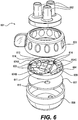
FIG. 5 is an exploded view of an alternative tube management device according to the present invention; -
FIG. 6 illustrates a variant of the tube management device displayed inFIG. 5 according to various embodiments; -
FIG. 7 is a top view of a tube restrictor plate and a tube stabilizer plate of the tube management device of the embodiment shown inFIG. 6 ; -
FIG. 8 illustrates a tube management device according to various embodiments. - Reference will now be made in detail to certain exemplary embodiments according to the present disclosure, certain examples of which are illustrated in the accompanying drawings. Wherever possible, the same reference numbers will be used throughout the drawings to refer to the same or like parts.
- In this application, the use of the singular includes the plural unless specifically stated otherwise. In this application, the use of "or" means "and/or" unless stated otherwise. Furthermore, the use of the term "including", as well as other forms such as "included" and "includes", is not limiting. The section headings used herein are for organizational purposes only and are not to be construed as limiting the subject matter described.
- As used herein, "adipose tissue" refers to adipose tissue obtained by any means including, for example, liposuction and/or tumescent liposuction. In addition, the adipose tissue may be substantially intact or may be altered by, for example, washing with saline, antimicrobials, detergents, or other agents; the addition of therapeutic agents such an analgesics, antimicrobials, and anti-inflammatories; the removal of some cells or acellular components; or disruption or alteration by the collection process itself including, for example, during liposuction or tumescent liposuction. The adipose tissue can be autologous tissue, allogeneic tissue, or xenogenic tissue (e.g., porcine tissue).
- As described above, some surgical procedures require use of tubes, hoses, or other conduits to transfer fluids, gases, and/or tissue products between a patient and a treatment system or device; or among systems and devices. Multi-step procedures are not uncommon and may require connection and disconnection of hoses from input and output ports. For example, a system for adipose tissue transfer and processing (e.g., adipose washing) can require over one hundred combined user actions and decisions, including enabling and disabling vacuum sources or adding or removing tissue or washing solutions to a tissue storage and treatment container. The maintenance and verification of tube connections during a medical procedure can be non-trivial, especially when the procedure has a time-sensitive component.
- Various human and animal tissues can be used to produce products for treating patients. For example, various tissue products have been produced for regeneration, repair, augmentation, reinforcement, and/or treatment of human tissues that have been damaged or lost due to various diseases and/or structural damage (e.g., from trauma, surgery, atrophy, and/or long-term wear and degeneration). Fat grafting, including autologous fat grafting, can be useful for a variety of clinical applications including facial fillers, breast augmentation, buttock augmentation/sculpting, augmentation of other tissue sites, correction of lumpectomy defects, cranial-facial defect correction, and correction of lipoplasty defects (divots).
- To prepare tissue for autologous fat grafting, tissue cleaning and processing must be performed. The process of grafting typically involves steps such as removal of tissue from a patient with a syringe or cannula. This tissue is pulled into a tissue processing container where unwanted components of the tissue can be separated and/or the tissue can be cleaned using various solutions. A typical system might include meshes for filtration and separation, cranks connected to mixing blades, and several input and output ports. Once the tissue is sufficiently prepared, it must be removed from the container and be injected or grafted back into the patient. During transfer steps, vacuum devices help move the tissue from location to location. However, it is desirable to disconnect the vacuum pressure during processing steps. In addition, the tissue-carrying tubes that are not in use during any given step should be blocked to maintain the sterility of the system.
- Turning to
FIG. 1 , an illustrative embodiment of atissue treatment system 100 is shown. As shown, thetissue treatment system 100 can include a container having anexterior wall 110 surrounding an interior volume. The interior of the container can also contain filters, mixing blades, hoses, and other components to enable washing and conditioning of tissue. Thesystem 100 can include atube management device 101 to facilitate operation of thesystem 100. Tubes can pass from the exterior of thesystem 100 to the interior throughports 102 of thetube management device 101, and tube restrictor devices (discussed below) within thetube management device 101 can control which tubes are open and which are blocked for a given system configuration. The system configuration is determined by the setting of amulti-position switch 103. In some embodiments, thesystem 100 can be provided with a carry handle for convenient handling by a user. - As used herein, the terms "tube," "hose," "conduit," or similar language will be used interchangeably and will be understood to refer to any passageway having a lumen configured to allow passage or fluids, gases, and/or tissue products therethrough.
- An exploded view of one embodiment of a
tube management device 101 is shown inFIG. 2 . Thetube management device 101 may include ports 102a, 102b, 102c and amulti-position switch 103. Tubes can pass through the ports 102a, 102b, 102c and then through a tuberestrictor plate 104 and atube stabilizer plate 107 before passing out of thedevice 101. Based on the position of themulti-position switch 103,restrictor elements 105 on the tuberestrictor plate 104 can allow or obstruct flow through each of the tubes. In some embodiments, the contents of thetube management device 101 can be contained within anexterior wall 108 that forms a body. In alternate embodiments, the components of thetube management device 101 can be attached directly to the structure of thecontainer 110. - The ports 102a, 102b, 102c can have a variety of configurations. In accordance with various embodiments, the ports 102a, 102b, 102c may be straight-walled or barbed; threaded or unthreaded; and have no fittings, luer fittings, swaged fittings, or any other type of connector suitable for a specific application. Although the ports 102a, 102b, 102c are depicted as extending out from the body of the
tube management device 101, the ports may also be threaded or unthreaded holes or recesses or may extend inward from the surface into the body of thedevice 101. Although only three ports are depicted inFIG. 2 , any number of ports can be chosen to match the number of tubes needed in a particular application. Substances including, but not limited to, gases, liquids, chemical solutions, and biological tissues can flow into or out from the ports 102a, 102b, 102c depending upon the position of the multi-position switch and the requirements of any particular step of the medical procedure. - The position of the
multi-position switch 103 can be used to switch among different device configurations. In some embodiments, themulti-position switch 103 is a rotating body or knob and the rotational angle of the body determines the switch state. In accordance with various embodiments, themulti-position switch 103 may be any mechanical or electronic switch (including rotational or linear throw switches) that, through appropriate linkages, can alter the state of openness of tubes passing through the device. In some embodiments, themulti-position switch 103 can include non-slip grips or similar features to facilitate easier operation by a user, in particular by a user wearing surgical gloves. The positions of themulti-position switch 103 may correspond to steps in a procedure. For example, the steps in a procedure might include liposuction/tissue extraction, hold and mix, irrigation, and vacuum/clear steps. - The tube restrictor
plate 104 can block or allow flow through tubes that pass through the tube through-holes of the plate through the use of flow-restricting devices. In accordance with various embodiments, and as depicted inFIGS. 2 and3 , the tuberestrictor plate 104 may be provided with flow-restrictingdevices 105 in the form of contoured radial slots. Theslots 105 can have a slot width that varies according to the desired action of the slot upon a tube for each angular position of the tuberestrictor plate 104. For example, eachslot 105 may include two slot widths that correspond to unrestricted flow in a tube and complete blockage of flow in a tube. Alternatively, each slot may have a range of widths corresponding to different levels of flow restriction. - In
FIG. 3 , a tuberestrictor plate 104 is shown overlaid upon atube stabilizer plate 107 with slots 105a, 105b, 105c indicated. The example embodiment of a tuberestrictor plate 104 shown inFIG. 3 illustrates tube through-holes in the form of contoured radial slots 105a, 105b, 105c suitable for atube management device 101 having amulti-position switch 103 with three positions. The contoured radial slots 105a, 105b, 105c of the tuberestrictor plate 104 are overlaid in this top view on the tube through-holes 115a, 115b, 115c of thetube stabilizer plate 107. In this figure, the position of tuberestrictor plate 104 with respect totube stabilizer plate 107 places slots 105a, 105b, 105c in the first position over tube through-holes 115a, 115b, 115c. Activation of the multi-position switch can cause the tuberestrictor plate 104 to rotate in the direction shown by the arrow while thetube stabilizer plate 107 stays in place. As a result, the radial slots can advance to the second or third position as needed. In accordance with various embodiments, thesystem 100 can be provided with a plurality oftube restrictor plates 104 having different arrangements of slots 105a, 105b, 105c intended for different procedures having different steps. In these embodiments, the user may choose one of the plurality oftube restrictor plates 104 to place within thebody 108 of thedevice 101 depending upon the application. - The tube restrictor
plate 104 may have locatingfeatures 106 that can interlock with themulti-position switch 103. The locating features 106 can help the user align the tube restrictor plate with themulti-position switch 103 and within thetube management device 101 so that the contoured radial slots 105a, 105b, 105c are properly in-line with their respective ports 102a, 102b, 102c. In addition, the locating features 106 can match with complementary features on the multi-position switch so that the switch's position reflects the proper tubing state within thetube management device 101. In some embodiments, the locating features 106 can fix themulti-position switch 103 to the tuberestrictor plate 104 such that they move in concert when the switch is rotated. - The
tube management device 101 can have atube stabilizer plate 107. Thetube stabilizer plate 107 may have tube through-holes 115 to allow tubes to pass therethrough. In some embodiments, the diameter of each of the tube through-holes 115 in thetube stabilizer plate 107 may be equal or approximately equal to the outer diameter of the corresponding tube that passes through thehole 115 to provide a secure fit around the outside of each tube without compression. Thetube stabilizer plate 107 can hold the tube in position so that activation or movement of the tuberestrictor plate 104 cannot twist, reorient, or move the tubes. - As discussed above, the
system 100 can be used to operate surgical systems, such as adipose tissue transfer systems. Accordingly, anexemplary decision matrix 400 for an adipose tissue transfer process is shown inFIG. 4 . The decision matrix may be used to determine the open/closed status of any tubes in the system during any steps of an adipose transfer procedure. In some embodiments, atissue treatment system 100 similar to that shown inFIG. 1 can have 4 tube inputs that are either open or blocked during a given step of a medical procedure. In a liposuction oraspiration 402 step, the tube to the liposuction cannula and the vacuum tube may be open while the irrigation tube and vent tube are closed. In a hold and mix or washing 404 step, all 4 inputs can be blocked. In an irrigation or transfer 406 step, the tube to the liposuction cannula and the vacuum tube may be closed while the irrigation tube and the vent tube can be open. In a vacuum/clear 408 step, the tube to the liposuction cannula and the irrigation tube may be closed while the vacuum tube and the vent tube can be open. - An alternate embodiment of a
tube management device 501 is shown inFIG. 5 . Thetube management device 501 can includeports 502 and amulti-position switch 503. Tubes can pass from theports 502 through a tuberestrictor plate 504 and atube stabilizer plate 507 before passing out of thedevice 501. Based on the position of the multi-position switch,restrictor elements 505 on the tuberestrictor plate 504 can allow or obstruct flow through each of the tubes. The contents of thetube management device 501 can be contained within anexterior wall 508 that forms a body. - As with the previously discussed embodiments, the ports can have a variety of configurations. For example, the
ports 502 may be straight-walled or barbed; threaded or unthreaded; and have no fittings, luer fittings, swaged fittings, or any other type of connector demanded by application-specific requirements. Althoughports 502 are depicted in this embodiment as extending out from the body of thetube management device 501, the ports may also be threaded or unthreaded recesses or holes or may extend inward from the device surface into the body of thedevice 501. Although only three ports are depicted inFIG. 5 , any number of ports can be chosen to match the number of tubes needed in a particular application. Substances including, but not limited to, gases, liquids, chemical solutions, and biological tissues can flow into or out from theports 502 depending upon the position of the multi-position switch and the requirements of any particular step of the surgical procedure. - The positions of the
multi-position switch 503 can be used to switch among different device configurations. In some embodiments, themulti-position switch 503 is a rotating body or knob and the rotational angle of the body determines the switch state. In accordance with various embodiments, themulti-position switch 503 may be any mechanical or electronic switch (including rotational or linear throw switches) that, through appropriate linkages, can alter the state of openness of tubes passing through the device. In some embodiments, themulti-position switch 503 can include non-slip grips or similar features to facilitate easier operation by a user, in particular by a user wearing surgical gloves. The positions of themulti-position switch 503 may correspond to steps in a procedure. For example, the steps in a procedure might include liposuction/tissue extraction, hold and mix, irrigation, and vacuum/clear steps. - The tube restrictor
plate 504 can block or allow flow through the tubes that pass through the tube through-holes 516 of the plate through the use of flow-restricting devices. The tube restrictorplate 504 may include an external ring 504a that is rotatably engaged with a central portion 504b. Tubes can pass through the tuberestrictor plate 504 through tube through-holes 516 adjacent to flow-restricting devices. In accordance with various embodiments and as depicted inFIG. 5 , the tuberestrictor plate 504 may be provided with flow-restricting devices in the form of a contouredcentral hub 512 on the central portion 504b and slidingblocks 505 that force the tubes against thehub 512 via theintegrated springs 514 attached to the external ring 504a. The slidingblocks 505 may be shaped as flat plates, cylinders, ovals, spheres, ovoid configuration, or any other shape that meets application-specific requirements. In some embodiments, the contouredcentral hub 512 may have an equal number of recesses to the number ofports 502, and each tube may pass through a tube through-hole 516 adjacent to a recess of the contoured central hub. When a slidingblock 505 attached to anintegrated spring 512 is in line with a recess of the contouredcentral hub 512, the force of the spring may extend the sliding block and force it against a tube. In some embodiments, the central portion 504b of the tuberestrictor plate 504 may be fixedly attached to thetube stabilizer plate 507. As themulti-position switch 503 changes from one position to another, the external ring 504a of thetube restriction plate 504 may rotate while the central portion 504b containing the contouredcentral hub 512 does not rotate relative to thetube stabilizer plate 507. - In accordance with various embodiments, the external ring 504a may be provided with a one-
way ratcheting mechanism 509. The teeth of the ratcheting mechanism can engage with apawl 511 positioned on the central portion 504b of thetube restriction plate 504 such that rotation of the external ring 504a is allowed in one direction but prevented in the opposite direction. Although thepawl 511 is depicted as being located on the central portion 504b in this embodiment, it will be apparent to those of ordinary skill in the art that the pawl could be attached at other points throughout thetube management device 501 such as the interior of themulti-position switch 503 or thetube stabilizer plate 507. - The
tube management device 501 can also include atube stabilizer plate 507. Thetube stabilizer plate 507 may have tube through-holes 515 to allow tubes to pass through. In some embodiments, the diameter of each of the tube through-holes 515 in thetube stabilizer plate 507 may be equal to the outer diameter of the corresponding tube that passes through the hole to provide a secure fit around the outside of each tube without compression. Thetube stabilizer plate 507 can hold the tube in position so that activation or movement of the tuberestrictor plate 504 cannot twist, reorient, or move the tubes. - Another embodiment of a tube management device is shown in
FIG. 6 . Thetube management device 601 can includeports 602 and amulti-position switch 603. Thedevice 601 can include atube stabilizer plate 607 and a tuberestrictor plate 604 containing flow restriction devices. The components of thedevice 601 can be enclosed within abody 608. - The
ports 602 are the connection between thetube management device 601 and the exterior world. In accordance with various embodiments, theports 602 may be straight-walled or barbed; threaded or unthreaded; and have no fittings, luer fittings, swaged fittings, or any other type of connector demanded by application-specific requirements. Although theports 602 are depicted in this embodiment as extending out from the body of thetube management device 601, the ports may also be threaded or unthreaded holes or may extend inward from the device surface into the body of thedevice 601. Although only three ports are depicted inFIG. 6 , it will be evident to one of ordinary skill in the art that any number ofports 602 can be chosen to match the number of tubes needed in a particular application. Fluids including, but not limited to, gases, liquids, chemical solutions, and biological tissues can flow into or out from theports 602 depending upon the position of the multi-position switch and the requirements of any particular step of the medical procedure. - The positions of the
multi-position switch 603 can be used to switch among different device configurations. In some embodiments, themulti-position switch 603 is a rotating body or knob and the rotational angle of the body determines the switch state. In accordance with various embodiments, themulti-position switch 603 may be any mechanical or electronic switch (including rotational or linear throw switches) that, through appropriate linkages, can alter the state of openness of tubes passing through the device. In some embodiments, themulti-position switch 603 can include non-slip grips or similar features to facilitate easier operation by a user, in particular by a user wearing surgical gloves. The positions of themulti-position switch 603 may correspond to steps in a procedure. For example, the steps in a procedure might include liposuction/tissue extraction, hold and mix, irrigation, and vacuum/clear steps. - The tube restrictor
plate 604 may include an external ring 604a that is rotatably engaged with a central portion 604b. Tubes may pass through tube through-holes 616 adjacent to flow-restricting devices. In accordance with various embodiments and as depicted inFIG. 6 , the tuberestrictor plate 604 may be provided with flow-restricting devices in the form of a contouredcentral hub 612 on the central portion 604b and slidingblocks 605 that force the tubes against thehub 612 via theintegrated springs 614 attached to the external ring 604a. The slidingblocks 605 may be shaped as flat plates, cylinders, ovals, spheres, eggs, or any other shape that meets application-specific requirements. In some embodiments, the contouredcentral hub 612 may have an equal number of recesses to the number ofports 602, and each tube may pass through a tube through-hole 616 adjacent to a recess of the contoured central hub. When a slidingblock 605 attached to anintegrated spring 612 is in line with a recess of the contouredcentral hub 612, the force of the spring may extend the sliding block and force it against a tube. As themulti-position switch 603 changes from one position to another, the external ring 604a of thetube restriction plate 604 may rotate while the central portion 604b containing the contouredcentral hub 612 does not rotate relative to thetube stabilizer plate 607. In accordance with various embodiments, the slidingblocks 605 andintegrated springs 614 can be placed at different radial depths using spacers 604c. - The
tube management device 601 can have atube stabilizer plate 607 in some embodiments. Thetube stabilizer plate 607 may have tube through-holes 615 to allow tubes to pass through. In preferred embodiments, the diameter of each of the tube through-holes 615 in thetube stabilizer plate 607 may be equal to the outer diameter of the corresponding tube that passes through the hole to provide a secure fit around the outside of each tube without compression. Thetube stabilizer plate 607 can hold the tube in position so that activation or movement of the tuberestrictor plate 604 cannot twist, reorient, or move the tubes. - A top view of the tube
restrictor plate 604 overlaid ontube stabilizer plate 607 of the embodiment ofFIG. 6 is shown inFIG. 7 . In accordance with various embodiments, the tuberestrictor plate 604 can haveslots 613 to allow the tubes to change position with respect to the contouredcentral hub 612 of the central portion 604b and the associated flow-restricting devices. In this way, a single embodiment of the tuberestrictor plate 604 can be used in more than one configuration. When a tube is in an "in" position, the tube passes near a recess of the contouredcentral hub 612 and can be closed by slidingblocks 605 attached to spacers 604c extending from the external ring 604a. When a tube is in an "out" position, the tube passes near an extended portion of the contouredcentral hub 612. In this position, the tube can be closed by slidingblocks 505 that are attached byintegrated springs 614 directly to the external ring 604a. In a preferred embodiment, slidingblocks 605 attached directly to the external ring 604a without spacers 604c cannot reach tubes adjacent to recesses of the contouredcentral hub 612. - In accordance with various embodiments, the external ring 604a may be provided with a one-
way ratcheting mechanism 609. The teeth of the ratcheting mechanism can engage with apawl 611 positioned on the central portion 604b of thetube restriction plate 604 such that rotation of the external ring 604a is allowed in one direction but prevented in the opposite direction. Although thepawl 611 is depicted as being located on the central portion 604b in this embodiment, it will be apparent to those of ordinary skill in the art that the pawl could be attached at other points throughout thetube management device 601 such as the interior of themulti-position switch 603 or thetube stabilizer plate 607. - A method of managing surgical conduits is also envisioned by the inventors. The method includes providing several tubes and several flow-restricting devices within a body where each of the flow-restricting devices is proximal to at least one of the tubes and providing a multi-position switch wherein the flow in a first subset of the tubes is restricted by the flow-restricting devices when the switch is in a first position and flow in a second subset of tubes different than the first subset is restricted by the flow-restricting devices when the switch is in a second position. The method concludes by switching from the first position of the multi-position switch to the second position.
- The step of providing several tubes and several flow-restricting devices within a body where each of the flow-restricting devices is proximal to at least one of the tubes may include, but is not limited to, passing tubes through
ports 102 and past flow-restrictingdevices 105 in atube management device 101 as described above in connection withFIGS. 1-3 . - The step of providing a multi-position switch wherein the flow in a first subset of the tubes is restricted by the flow-restricting devices when the switch is in a first position and flow in a second subset of tubes different than the first subset is restricted by the flow-restricting devices when the switch is in a second position may include, but is not limited to, providing a
multi-position switch 103 in atube management device 101 as described above in connection withFIGS. 1-3 . - The step of switching from the first position of the multi-position switch to the second position may include, but is not limited to, switching a
multi-position switch 103 from a first position to a second position as described above in connection withFIGS. 1 and2 . - An exploded view of an alternative embodiment of a
tube management device 801 is shown inFIG. 8 . Thetube management device 801 may include ports 802a, 802b, 802c and amulti-position switch 803.Tubes 812 pass through the ports 802a, 802b, 802c and then through a tuberestrictor plate 804 and atube stabilizer plate 807 before passing out of thedevice 801. Based on the position of themulti-position switch 803,restrictor elements 805 on the tuberestrictor plate 804 can allow or obstruct flow through each of thetubes 812. In some embodiments, the contents of thetube management device 801 can be contained within anexterior wall 808 that forms a body. - The ports 802a, 802b, 802c can have a variety of configurations as described previously with respect to
FIG. 2 . In accordance with various embodiments, the ports 802a, 802b, 802c may be straight-walled or barbed; threaded or unthreaded; and have no fittings, luer fittings, swaged fittings, or any other type of connector suitable for a specific application. Although the ports 802a, 802b, 802c are depicted as extending out from the body of thetube management device 801, the ports may also be threaded or unthreaded holes or recesses or may extend inward from the surface into the body of thedevice 801. Although only three ports are depicted inFIG. 8 , any number of ports can be chosen to match the number oftubes 812 needed in a particular application. Substances including, but not limited to, gases, liquids, chemical solutions, and biological tissues can flow into or out oftubes 812 passing through the ports 802a, 802b, 802c depending upon the position of the multi-position switch and the requirements of any particular step of a medical procedure. - As described above with reference to
FIG. 2 , the position of themulti-position switch 803 can be used to switch among different device configurations. In some embodiments, themulti-position switch 803 is a rotating body or knob, and the rotational angle of the body determines the switch state. In accordance with various embodiments, themulti-position switch 803 may be any mechanical or electronic switch (including rotational or linear throw switches) that, through appropriate linkages, can alter the state of openness of thetubes 812. In some embodiments, themulti-position switch 803 can include non-slip grips or similar features to facilitate easier operation by a user, in particular by a user wearing surgical gloves. The positions of themulti-position switch 803 may correspond to steps in a procedure. For example, the steps in a procedure might include liposuction/tissue extraction, hold and mix, irrigation, and vacuum/clear steps. - The tube restrictor
plate 804 can block or allow flow through thetubes 812 as they pass through the plate through the use of flow-restricting devices. Similar to the embodiments depicted inFIGS. 2 and3 , the tuberestrictor plate 804 may be provided with both flow-restricting devices and tube through-holes in the form of contouredradial slots 805. In alternative embodiments, the flow-restricting devices can be similar to those described above with reference to the embodiments ofFIGS. 5 and6 . Theslots 805 can have a slot width that varies according to the desired action of the slot upon atube 812 for each angular position of the tuberestrictor plate 804. For example, eachslot 805 may include two slot widths that correspond to unrestricted flow in atube 812 and complete blockage of flow in atube 812. Alternatively, each slot may have a range of widths corresponding to different levels of flow restriction. - The tube restrictor
plate 804 may have locatingfeatures 806 that can interlock with themulti-position switch 803. The locating features 806 can help the user align the tuberestrictor plate 804 with themulti-position switch 803 and within thetube management device 801 so that the contouredradial slots 805 are properly in-line with their respective ports 802a, 802b, 802c. In addition, the locating features 806 can match with complementary features on the multi-position switch so that the switch's position reflects the proper tubing state within thetube management device 801. In some embodiments, the locating features 806 can fix themulti-position switch 803 to the tuberestrictor plate 804 such that they move in concert when the switch is rotated. - The
tube management device 801 can have atube stabilizer plate 807. Thetube stabilizer plate 807 may have tube through-holes 815 to allow tubes to pass therethrough. In some embodiments, the diameter of each of the tube through-holes 815 in thetube stabilizer plate 807 may be equal or approximately equal to the outer diameter of the corresponding tube that passes through the hole to provide a secure fit around the outside of each tube without compression. Thetube stabilizer plate 807 can hold the tube in position so that activation or movement of the tuberestrictor plate 804 cannot twist, reorient, or move the tubes. - The
tubes 812 oftube management device 801 can be made of any material that meets application-specific requirements. Thetubes 812 may be made of, for example but not limited to, PVC, high-density polyethylene, nylon, latex, silicone, polyurethane, TYGON®, or any non-reactive tubing or hose. As depicted inFIG. 8 , thetubes 812 may extend out of the ports 802a, 802b, 802c or may terminate within or below the ports 802a, 802b, 802c. Thetubes 812 may be permanently attached to thetube management device 801, for example, at the ports 802a, 802b, 802c orbody 808, or thetubes 812 may be removable and/or replaceable. In accordance with various embodiments, thetubes 812 may be disposed of after each procedure and replaced withnew tubes 812 to allow for reuse oftube management device 801 for multiple procedures.
Claims (15)
- A tissue treatment system (100), comprising:a container (110), including:an exterior wall surrounding an interior volume for holding tissue; anda filter for processing tissue;a tube management device (101, 501, 601, 801), including:a tube restrictor plate (104, 504, 604, 804) having a plurality of tube through-holes (105, 105a, 105b, 105c, 805);a tube stabilizer plate (107, 507, 607, 807) having a plurality of tube through-holes (115, 115a, 115b, 115c, 515, 615, 815);a plurality of flow-restricting devices disposed on the tube restrictor plate adjacent to the plurality of tube through-holes; anda multi-position switch (103, 503, 603, 803);wherein a plurality of tubes (812) passes through the plurality of tube through-holes, andwherein setting the multi-position switch (103, 503, 603, 803) to a first position causes the plurality of flow-restricting devices to restrict the flow in a first subset of the plurality of tubes (812) to transfer tissue from a patient to the interior volume, setting the multi-position switch (103, 503, 603, 803) to a second position causes the plurality of flow-restricting devices to restrict the flow in a second subset of the plurality of tubes (812) to allow processing of the tissue in the interior volume, and setting the multi-position switch (103, 503, 603, 803) to a third position causes the plurality of flow-restricting devices to restrict the flow in a third subset of the plurality of tubes (812) to allow transfer of the tissue out of the interior volume.
- The system of claim 1, wherein the plurality of flow-restricting devices includes contoured radial slots (105a, 105b, 105c, 805) located on the tube restrictor plate (104, 504, 604, 804).
- The system of claim 2, wherein the tube restrictor plate (104, 504, 604, 804) is chosen from a set of tube restrictor plates (104, 504, 604, 804) having at least two plates with differently contoured radial slots (105a, 105b, 105c, 805).
- The system of claim 1, wherein the one or more flow-restricting devices include a plurality of sliding blocks (505, 605), a subset of the plurality of sliding blocks being engaged to restrict flow within a first subset of the plurality of tubes (812).
- The system of claim 1, wherein the multi-position switch (103, 503, 603, 803) is configured to allow switching in only one direction.
- The system of claim 5, further comprising a ratchet mechanism (509, 609) to allow the multi-position switch (103, 503, 603, 803) to move in only one direction.
- The system of claim 1, further comprising at least one of a mixing blade or filter to facilitate tissue washing or treatment.
- The system of claim 1, wherein the positions of the multi-position switch (103, 503, 603, 803) correspond to process steps (402, 404, 406, 408) in a tissue washing or processing procedure.
- A method of managing surgical conduits of the tissue treatment system of claim 1, comprising:providing a plurality of tubes and a plurality of flow-restricting devices within a body, each of the flow-restricting devices proximal to at least one of the plurality of tubes (812);providing a multi-position switch (103, 503, 603, 803) wherein flow in a first subset of the plurality of tubes (812) is restricted by the plurality of flow-restricting devices when the multi-position switch (103, 503, 603, 803) is in a first position and flow in a second subset of the plurality of tubes (812) different than the first subset is restricted by the plurality of flow-restricting devices when the multi-position switch (103, 503, 603, 803) is in a second position; andswitching from the first position of the multi-position switch (103, 503, 603, 803) to the second position of the multi-position switch (103, 503, 603, 803).
- The method of claim 9, wherein the plurality of flow-restricting devices includes contoured radial slots (105a, 105b, 105c, 805) located on a tube restrictor plate (104, 504, 604, 804).
- The method of claim 10, further comprising a tube stabilizer plate (107, 507, 607, 807) through which the plurality of tubes (812) passes to stabilize the tubes.
- The method of claim 9, wherein the tube restrictor plate (104, 504, 604, 804) is chosen from a set of rotatable discs having at least two discs with differently contoured radial slots (105a, 105b, 105c, 805).
- The method of claim 9, wherein the one or more flow-restricting devices include a plurality of sliding blocks, a subset of the plurality of sliding blocks being engaged to restrict flow within a first subset of the plurality of tubes (812).
- The method of claim 13, further comprising performing a tissue aspiration step of a tissue washing or processing procedure when the multi-position switch (103, 503, 603, 803) is in the first position.
- The method of claim 13, further comprising performing a tissue washing step of a tissue washing or processing procedure when the multi-position switch (103, 503, 603, 803) is in the second position, OR comprising performing a tissue transfer step of a tissue washing or processing procedure when the multi-position switch (103, 503, 603, 803) is in a third position.
Priority Applications (1)
| Application Number | Priority Date | Filing Date | Title |
|---|---|---|---|
| EP19211591.3A EP3633027A1 (en) | 2015-10-21 | 2016-10-21 | Methods for tube management |
Applications Claiming Priority (2)
| Application Number | Priority Date | Filing Date | Title |
|---|---|---|---|
| US201562244398P | 2015-10-21 | 2015-10-21 | |
| PCT/US2016/058158 WO2017070493A1 (en) | 2015-10-21 | 2016-10-21 | Systems and methods for tube management |
Related Child Applications (1)
| Application Number | Title | Priority Date | Filing Date |
|---|---|---|---|
| EP19211591.3A Division EP3633027A1 (en) | 2015-10-21 | 2016-10-21 | Methods for tube management |
Publications (2)
| Publication Number | Publication Date |
|---|---|
| EP3365430A1 EP3365430A1 (en) | 2018-08-29 |
| EP3365430B1 true EP3365430B1 (en) | 2019-12-04 |
Family
ID=57233901
Family Applications (2)
| Application Number | Title | Priority Date | Filing Date |
|---|---|---|---|
| EP19211591.3A Withdrawn EP3633027A1 (en) | 2015-10-21 | 2016-10-21 | Methods for tube management |
| EP16791208.8A Active EP3365430B1 (en) | 2015-10-21 | 2016-10-21 | Systems and methods for tube management |
Family Applications Before (1)
| Application Number | Title | Priority Date | Filing Date |
|---|---|---|---|
| EP19211591.3A Withdrawn EP3633027A1 (en) | 2015-10-21 | 2016-10-21 | Methods for tube management |
Country Status (12)
| Country | Link |
|---|---|
| US (2) | US10286122B2 (en) |
| EP (2) | EP3633027A1 (en) |
| JP (2) | JP6818020B2 (en) |
| KR (1) | KR20180072729A (en) |
| CN (1) | CN108350424A (en) |
| AU (1) | AU2016342002A1 (en) |
| BR (1) | BR112018008050A2 (en) |
| CA (1) | CA3002078A1 (en) |
| ES (1) | ES2775597T3 (en) |
| MX (1) | MX2018004956A (en) |
| RU (1) | RU2728767C2 (en) |
| WO (1) | WO2017070493A1 (en) |
Families Citing this family (6)
| Publication number | Priority date | Publication date | Assignee | Title |
|---|---|---|---|---|
| EP2834344B1 (en) | 2012-09-06 | 2016-07-20 | The GID Group, Inc. | Tissue processing apparatus and method for processing adipose tissue |
| US9248384B2 (en) | 2013-10-02 | 2016-02-02 | Allergan, Inc. | Fat processing system |
| CN108291201A (en) | 2015-10-21 | 2018-07-17 | 生命细胞公司 | System and method for medical treatment device control |
| US10472603B2 (en) | 2016-08-30 | 2019-11-12 | Lifecell Corporation | Systems and methods for medical device control |
| CN112739294A (en) * | 2018-09-19 | 2021-04-30 | 帝皇工业有限公司 | Pipe fitting connecting system for negative pressure wound treatment |
| KR20230146293A (en) * | 2022-04-12 | 2023-10-19 | 연세대학교 산학협력단 | Wound retractor inserter |
Family Cites Families (104)
| Publication number | Priority date | Publication date | Assignee | Title |
|---|---|---|---|---|
| US3791524A (en) * | 1972-04-13 | 1974-02-12 | Atomic Energy Commission | Tissue collector |
| US3855997A (en) * | 1973-07-11 | 1974-12-24 | Cinco Medical Health Supply Co | Sterile specimen trap |
| US4681571A (en) | 1981-04-23 | 1987-07-21 | C. R. Bard, Inc. | Suction canister with disposable liner and check valve |
| US4457339A (en) * | 1982-03-03 | 1984-07-03 | Coulter Electronics, Inc. | Multiprogrammable pinch valve module |
| JPS6040067A (en) * | 1983-08-15 | 1985-03-02 | テルモ株式会社 | Medical container |
| US5372945A (en) | 1985-06-06 | 1994-12-13 | Alchas; Paul G. | Device and method for collecting and processing fat tissue and procuring microvessel endothelial cells to produce endothelial cell product |
| US4753634A (en) | 1986-10-31 | 1988-06-28 | Johnson Gerald W | Fat collection syringe |
| US4821996A (en) * | 1987-01-28 | 1989-04-18 | Baxter Travenol Laboratories, Inc. | Fluid flow control valve and transfer set |
| SE8801098D0 (en) | 1988-03-24 | 1988-03-24 | Pharmacia Ab | APPARATUS AND METHOD FOR AUTOMATIC EXTRACTION OF EXTRA-CHROMOSOMAL DNA FROM A CELL SUSPENSION IN A CONTAINER |
| US4988623A (en) | 1988-06-30 | 1991-01-29 | The United States Of America As Represented By The Administrator Of The National Aeronautics And Space Administration | Rotating bio-reactor cell culture apparatus |
| US5301685A (en) | 1989-01-10 | 1994-04-12 | Guirguis Raouf A | Method and apparatus for obtaining a cytology monolayer |
| US5601707A (en) | 1990-07-13 | 1997-02-11 | Isco, Inc. | Apparatus and method for supercritical fluid extraction or supercritical fluid chromatography |
| US5336616A (en) | 1990-09-12 | 1994-08-09 | Lifecell Corporation | Method for processing and preserving collagen-based tissues for transplantation |
| NZ242533A (en) | 1991-05-03 | 1995-05-26 | Becton Dickinson Co | Device for collecting and processing fat tissue; vessel with rinsing and digesting chamber, drain chamber and isolation chamber |
| US5610074A (en) | 1993-02-24 | 1997-03-11 | Beritashvili; David R. | Centrifugal method and apparatus for isolating a substance from a mixture of substances in a sample liquid |
| US5409833A (en) | 1993-07-01 | 1995-04-25 | Baxter International Inc. | Microvessel cell isolation apparatus |
| RU2116802C1 (en) * | 1994-08-09 | 1998-08-10 | Московский областной научно-исследовательский клинический институт | Device for washing abdominal cavity |
| US5888409A (en) | 1995-06-07 | 1999-03-30 | Cedars-Sinai Medical Center | Methods for cell isolation and collection |
| US6200606B1 (en) | 1996-01-16 | 2001-03-13 | Depuy Orthopaedics, Inc. | Isolation of precursor cells from hematopoietic and nonhematopoietic tissues and their use in vivo bone and cartilage regeneration |
| US5785640A (en) | 1996-05-23 | 1998-07-28 | Kresch; Arnold J. | Method for treating female incontinence |
| US5901717A (en) | 1996-08-16 | 1999-05-11 | Dornoch Medical Systems, Inc. | Liquid waste disposal and canister flushing system and method |
| US5911700A (en) | 1997-03-11 | 1999-06-15 | Microaire Surgical Instruments | Power assisted liposuction and lipoinjection equipment |
| US5786207A (en) | 1997-05-28 | 1998-07-28 | University Of Pittsburgh | Tissue dissociating system and method |
| AU8476698A (en) | 1997-07-03 | 1999-01-25 | Osiris Therapeutics, Inc. | Human mesenchymal stem cells from peripheral blood |
| USD401336S (en) | 1997-07-24 | 1998-11-17 | Somnus Medical Technologies, Inc. | Tissue ablation device |
| JP3965796B2 (en) * | 1997-08-19 | 2007-08-29 | 株式会社ジェイ・エム・エス | Medical fluid flow switching device |
| US5853398A (en) * | 1997-12-19 | 1998-12-29 | Baxter International Inc. | Container with pivoting tube clamp |
| EP1060242A4 (en) | 1998-01-23 | 2003-09-17 | Imclone Systems Inc | Purified populations of stem cells |
| USD424194S (en) | 1998-10-16 | 2000-05-02 | Bio-Plexus, Inc. | Catheter needle assembly |
| US20010030152A1 (en) | 1999-12-20 | 2001-10-18 | Wright David A. | Compound mixer and filter for lapping machine |
| US6733537B1 (en) | 2000-06-02 | 2004-05-11 | Reconstructive Technologies, Inc. | Apparatus for tissue expansion using pulsatile motion |
| CN1187356C (en) | 2000-11-22 | 2005-02-02 | 南宁枫叶药业有限公司 | System for extracting tetradoxin with high yield |
| US6544788B2 (en) | 2001-02-15 | 2003-04-08 | Vijay Singh | Disposable perfusion bioreactor for cell culture |
| US6626890B2 (en) | 2001-06-06 | 2003-09-30 | Tony R. Brown | Fat removal device and method |
| US7172572B2 (en) | 2001-10-04 | 2007-02-06 | Boston Scientific Scimed, Inc. | Manifold system for a medical device |
| US7264608B2 (en) | 2001-12-05 | 2007-09-04 | Fenwal, Inc. | Manual processing systems and methods for providing blood components conditioned for pathogen inactivation |
| US7514075B2 (en) | 2001-12-07 | 2009-04-07 | Cytori Therapeutics, Inc. | Systems and methods for separating and concentrating adipose derived stem cells from tissue |
| US7595043B2 (en) | 2001-12-07 | 2009-09-29 | Cytori Therapeutics, Inc. | Method for processing and using adipose-derived stem cells |
| DK1921133T3 (en) | 2001-12-07 | 2015-08-24 | Cytori Therapeutics Inc | System for processing lipoaspiratceller |
| US7585670B2 (en) | 2001-12-07 | 2009-09-08 | Cytori Therapeutics, Inc. | Automated methods for isolating and using clinically safe adipose derived regenerative cells |
| US7651684B2 (en) | 2001-12-07 | 2010-01-26 | Cytori Therapeutics, Inc. | Methods of using adipose tissue-derived cells in augmenting autologous fat transfer |
| US9144583B2 (en) | 2002-03-29 | 2015-09-29 | Tissue Genesis, Inc. | Cell separation apparatus and methods of use |
| AU2003249642A1 (en) | 2002-05-24 | 2003-12-12 | Biomet Manufacturing Corp. | Apparatus and method for separating and concentrating fluids containing multiple components |
| US7361368B2 (en) | 2002-06-28 | 2008-04-22 | Advanced Cardiovascular Systems, Inc. | Device and method for combining a treatment agent and a gel |
| US7176034B2 (en) | 2002-07-03 | 2007-02-13 | St. Joseph's Healthcare | Apparatus and method for filtering biological samples |
| AU2003284558A1 (en) | 2002-11-19 | 2004-06-15 | Sekisui Chemical Co Ltd | Plasma or serum separation membrane and filter apparatus including the plasma or serum separation membrane |
| WO2004047651A2 (en) | 2002-11-25 | 2004-06-10 | Boston Scientific Limited | Injection device for treating mammalian body |
| KR100473568B1 (en) | 2003-01-25 | 2005-03-10 | 이희영 | Closed loop fat transplantation system |
| USD492995S1 (en) | 2003-04-03 | 2004-07-13 | Valera Pharmaceuticals, Inc. | Implanting device |
| DE10327254B4 (en) | 2003-06-17 | 2010-01-28 | Disetronic Licensing Ag | Modular infusion pump |
| CA2539177A1 (en) | 2003-09-22 | 2005-04-07 | Lawrence Bullen | Tissue dissociation device |
| EP1691885B1 (en) * | 2003-12-11 | 2014-04-02 | Gambro Lundia AB | Switching device and apparatus for controlling flow of a fluid |
| US7588732B2 (en) | 2004-03-30 | 2009-09-15 | Genesis Biosystems, Inc. | Autologus tissue harvesting and irrigation device |
| US20060051865A1 (en) | 2004-08-31 | 2006-03-09 | Higgins Joel C | Systems and methods for isolating stromal cells from adipose tissue and uses thereof |
| US20140193852A9 (en) | 2004-12-23 | 2014-07-10 | Erik Vossman | Adipose tissue collection and pre-processing devices for use in liposuction procedure |
| US7708152B2 (en) | 2005-02-07 | 2010-05-04 | Hanuman Llc | Method and apparatus for preparing platelet rich plasma and concentrates thereof |
| US7789872B2 (en) | 2005-03-23 | 2010-09-07 | Shippert Ronald D | Tissue transplantation method and apparatus |
| US7780649B2 (en) | 2005-03-23 | 2010-08-24 | Shippert Ronald D | Tissue transplantation method and apparatus |
| US7794449B2 (en) | 2005-03-23 | 2010-09-14 | Shippert Ronald D | Tissue transplantation method and apparatus |
| US8062286B2 (en) | 2005-03-23 | 2011-11-22 | Shippert Ronald D | Tissue transplantation method and apparatus |
| US8622997B2 (en) | 2005-03-23 | 2014-01-07 | Ronald D. Shippert | Tissue transfer method and apparatus |
| US7713232B2 (en) | 2005-11-04 | 2010-05-11 | Medrad, Inc. | System for washing and processing of cells for delivery thereof to tissue |
| US7758556B2 (en) | 2006-03-23 | 2010-07-20 | Perez-Cruet Miguelangelo J | Device for collecting bone material during a surgical procedure |
| US20090042267A1 (en) | 2006-04-07 | 2009-02-12 | Waste To Water Corporation | Food waste treatment device using microorganisms |
| US20070248575A1 (en) | 2006-04-19 | 2007-10-25 | Jerome Connor | Bone graft composition |
| US7732190B2 (en) | 2006-07-31 | 2010-06-08 | Advanced Cardiovascular Systems, Inc. | Modified two-component gelation systems, methods of use and methods of manufacture |
| USD575393S1 (en) | 2006-10-19 | 2008-08-19 | Medical Components, Inc. | Catheter tunneler adapter |
| WO2009055610A1 (en) | 2007-10-26 | 2009-04-30 | Cytori Therapeutics, Inc. | Syringe system for controlled delivery or removal of material |
| US8309342B2 (en) | 2007-12-04 | 2012-11-13 | Ingeneron, Inc. | Apparatus and methods for cell isolation |
| US20090181104A1 (en) | 2007-12-14 | 2009-07-16 | Gino Rigotti | Breast reconstruction or augmentation using computer-modeled deposition of processed adipose tissue |
| JP5078020B2 (en) * | 2008-02-13 | 2012-11-21 | オリンパス株式会社 | Centrifuge container |
| US20110009822A1 (en) | 2008-02-21 | 2011-01-13 | Poul Torben Nielsen | Dispenser for local anaesthetics and other liquids |
| EP2254991B1 (en) | 2008-02-29 | 2018-08-22 | Biomet Manufacturing, LLC | A system and process for separating a material |
| US8292839B2 (en) * | 2008-04-09 | 2012-10-23 | O'neill William G | Recirculation switch for blood cardioplegia |
| EP2326369B1 (en) | 2008-05-30 | 2018-04-18 | Allergan, Inc. | Injection device for soft-tissue augmentation fillers, bioactive agents and other biocompatible materials in liquid or gel form |
| WO2009149250A1 (en) | 2008-06-04 | 2009-12-10 | Kci Licensing, Inc. | Reduced-pressure, liquid-collection canister with multi-orientation filter |
| FR2943355B1 (en) | 2009-03-18 | 2011-04-08 | Sartorius Stedim Biotech Sa | RECIPIENT-MIXER WITH SHAFT BEARING IN SUPERIOR PART |
| US8293532B2 (en) | 2009-03-26 | 2012-10-23 | Dow AgroSciences, L.L.C. | Method and apparatus for tissue transfer |
| US8333740B2 (en) | 2009-05-01 | 2012-12-18 | Shippert Ronald D | Tissue transfer cannula |
| US8100874B1 (en) | 2009-05-22 | 2012-01-24 | Donnell Mark Jordan | Tissue refining device |
| US8366694B1 (en) | 2009-05-22 | 2013-02-05 | Donnell Mark Jordan | Tissue refining device |
| JP5368189B2 (en) | 2009-06-30 | 2013-12-18 | 株式会社イノアックコーポレーション | Air intake duct |
| KR101679671B1 (en) | 2009-10-27 | 2016-11-28 | 도병록 | System for extracting regenerative cells |
| KR101316573B1 (en) | 2009-10-27 | 2013-10-15 | 도병록 | System and unit for extracting regenerative cells |
| US20110117650A1 (en) | 2009-11-10 | 2011-05-19 | Riordan Neil H | Vessel and method for isolating cells from tissue portions |
| US20110198353A1 (en) | 2010-02-12 | 2011-08-18 | Tsao Yu-Yao | Waste liquid guide device with quickly replaceable inner bag |
| WO2013106655A1 (en) | 2012-01-11 | 2013-07-18 | The Gid Group, Inc. | Method for processing adipose tissue and processing apparatus |
| US9206387B2 (en) | 2010-07-09 | 2015-12-08 | The Gid Group, Inc. | Method and apparatus for processing adipose tissue |
| EP2590695A4 (en) | 2010-07-09 | 2017-09-06 | The Gid Group, Inc. | Apparatus and methods relating to collecting and processing human biological material containing adipose |
| JP6072684B2 (en) | 2010-08-06 | 2017-02-01 | ザ ジェネラル ホスピタル コーポレーション ディー/ビー/エイ マサチューセッツ ジェネラル ホスピタル | Cell treatment system and cell treatment apparatus |
| CA141113S (en) | 2010-12-23 | 2012-01-23 | Profibrix Bv | Dispenser for pharmaceutical powder formulations |
| EP2654824B1 (en) | 2010-12-23 | 2022-02-09 | Robert Krensky | Intra operative blood recovery system |
| US9314568B2 (en) | 2011-02-11 | 2016-04-19 | Lifecell Corporation | Devices and methods for tissue transfer |
| US9446189B2 (en) | 2011-02-11 | 2016-09-20 | Lifecell Corporation | Tissue transfer systems |
| US8632498B2 (en) | 2011-02-11 | 2014-01-21 | TauTona Group Research and Development Company, L.L.C. | Tissue transfer systems |
| WO2012116100A1 (en) | 2011-02-22 | 2012-08-30 | Sound Surgical Technologies Llc | Canister for autologous fat transfer |
| US8887770B1 (en) * | 2011-03-17 | 2014-11-18 | Ronald D. Shippert | Vessel fill control method and apparatus |
| WO2012139593A2 (en) | 2011-04-15 | 2012-10-18 | Rigshospitalet Copenhagen University Hospital | System and method for injecting a substance into a human body |
| USD687549S1 (en) | 2011-10-24 | 2013-08-06 | Ethicon Endo-Surgery, Inc. | Surgical instrument |
| USD679011S1 (en) | 2011-10-31 | 2013-03-26 | Olympus Medical Systems Corp. | Handle of surgical instrument |
| AU2012352199B2 (en) * | 2011-12-16 | 2017-08-17 | Stryker Corporation | Specimen trap with a removable catch tray for retrieving tissue samples from a fluid stream during a medical procedure |
| BR302012003126S1 (en) | 2011-12-23 | 2014-10-14 | Karls Storz Gmbh & Co Kg | CONFIGURATION APPLIED IN HANDLE FOR MEDICAL INSTRUMENT |
| CA2875363A1 (en) | 2012-05-30 | 2013-12-05 | Lifecell Corporation | Device for harvesting, processing, and transferring adipose tissue |
| US10472603B2 (en) | 2016-08-30 | 2019-11-12 | Lifecell Corporation | Systems and methods for medical device control |
-
2016
- 2016-10-21 EP EP19211591.3A patent/EP3633027A1/en not_active Withdrawn
- 2016-10-21 CA CA3002078A patent/CA3002078A1/en not_active Abandoned
- 2016-10-21 BR BR112018008050A patent/BR112018008050A2/en not_active IP Right Cessation
- 2016-10-21 KR KR1020187013846A patent/KR20180072729A/en unknown
- 2016-10-21 EP EP16791208.8A patent/EP3365430B1/en active Active
- 2016-10-21 US US15/299,966 patent/US10286122B2/en active Active
- 2016-10-21 MX MX2018004956A patent/MX2018004956A/en unknown
- 2016-10-21 ES ES16791208T patent/ES2775597T3/en active Active
- 2016-10-21 RU RU2018116602A patent/RU2728767C2/en active
- 2016-10-21 JP JP2018520107A patent/JP6818020B2/en active Active
- 2016-10-21 CN CN201680061475.9A patent/CN108350424A/en active Pending
- 2016-10-21 WO PCT/US2016/058158 patent/WO2017070493A1/en active Application Filing
- 2016-10-21 AU AU2016342002A patent/AU2016342002A1/en not_active Abandoned
-
2019
- 2019-03-29 US US16/369,491 patent/US20190224386A1/en not_active Abandoned
-
2020
- 2020-12-25 JP JP2020216317A patent/JP2021058661A/en not_active Withdrawn
Non-Patent Citations (1)
| Title |
|---|
| None * |
Also Published As
| Publication number | Publication date |
|---|---|
| JP2018538024A (en) | 2018-12-27 |
| JP6818020B2 (en) | 2021-01-20 |
| AU2016342002A1 (en) | 2018-05-10 |
| EP3365430A1 (en) | 2018-08-29 |
| JP2021058661A (en) | 2021-04-15 |
| US20190224386A1 (en) | 2019-07-25 |
| WO2017070493A1 (en) | 2017-04-27 |
| US20170112976A1 (en) | 2017-04-27 |
| BR112018008050A2 (en) | 2018-10-23 |
| CN108350424A (en) | 2018-07-31 |
| CA3002078A1 (en) | 2017-04-27 |
| RU2018116602A3 (en) | 2020-02-20 |
| US10286122B2 (en) | 2019-05-14 |
| KR20180072729A (en) | 2018-06-29 |
| ES2775597T3 (en) | 2020-07-27 |
| RU2728767C2 (en) | 2020-07-31 |
| EP3633027A1 (en) | 2020-04-08 |
| MX2018004956A (en) | 2018-09-12 |
| RU2018116602A (en) | 2019-11-21 |
Similar Documents
| Publication | Publication Date | Title |
|---|---|---|
| EP3365430B1 (en) | Systems and methods for tube management | |
| US10314955B2 (en) | Systems and methods for medical device control | |
| US11091733B2 (en) | Systems and methods for medical device control | |
| US20180361035A1 (en) | Power assisted lipoplasty | |
| US20200182757A1 (en) | Devices, systems, and methods for tissue processing | |
| KR20190097862A (en) | Suction apparatus having a plurality of ports |
Legal Events
| Date | Code | Title | Description |
|---|---|---|---|
| STAA | Information on the status of an ep patent application or granted ep patent |
Free format text: STATUS: UNKNOWN |
|
| STAA | Information on the status of an ep patent application or granted ep patent |
Free format text: STATUS: THE INTERNATIONAL PUBLICATION HAS BEEN MADE |
|
| PUAI | Public reference made under article 153(3) epc to a published international application that has entered the european phase |
Free format text: ORIGINAL CODE: 0009012 |
|
| STAA | Information on the status of an ep patent application or granted ep patent |
Free format text: STATUS: REQUEST FOR EXAMINATION WAS MADE |
|
| 17P | Request for examination filed |
Effective date: 20180420 |
|
| AK | Designated contracting states |
Kind code of ref document: A1 Designated state(s): AL AT BE BG CH CY CZ DE DK EE ES FI FR GB GR HR HU IE IS IT LI LT LU LV MC MK MT NL NO PL PT RO RS SE SI SK SM TR |
|
| AX | Request for extension of the european patent |
Extension state: BA ME |
|
| RAP1 | Party data changed (applicant data changed or rights of an application transferred) |
Owner name: LIFECELL CORPORATION |
|
| DAV | Request for validation of the european patent (deleted) | ||
| DAX | Request for extension of the european patent (deleted) | ||
| GRAP | Despatch of communication of intention to grant a patent |
Free format text: ORIGINAL CODE: EPIDOSNIGR1 |
|
| STAA | Information on the status of an ep patent application or granted ep patent |
Free format text: STATUS: GRANT OF PATENT IS INTENDED |
|
| INTG | Intention to grant announced |
Effective date: 20190308 |
|
| GRAJ | Information related to disapproval of communication of intention to grant by the applicant or resumption of examination proceedings by the epo deleted |
Free format text: ORIGINAL CODE: EPIDOSDIGR1 |
|
| STAA | Information on the status of an ep patent application or granted ep patent |
Free format text: STATUS: REQUEST FOR EXAMINATION WAS MADE |
|
| INTC | Intention to grant announced (deleted) | ||
| GRAR | Information related to intention to grant a patent recorded |
Free format text: ORIGINAL CODE: EPIDOSNIGR71 |
|
| GRAS | Grant fee paid |
Free format text: ORIGINAL CODE: EPIDOSNIGR3 |
|
| STAA | Information on the status of an ep patent application or granted ep patent |
Free format text: STATUS: GRANT OF PATENT IS INTENDED |
|
| GRAJ | Information related to disapproval of communication of intention to grant by the applicant or resumption of examination proceedings by the epo deleted |
Free format text: ORIGINAL CODE: EPIDOSDIGR1 |
|
| GRAR | Information related to intention to grant a patent recorded |
Free format text: ORIGINAL CODE: EPIDOSNIGR71 |
|
| GRAS | Grant fee paid |
Free format text: ORIGINAL CODE: EPIDOSNIGR3 |
|
| GRAJ | Information related to disapproval of communication of intention to grant by the applicant or resumption of examination proceedings by the epo deleted |
Free format text: ORIGINAL CODE: EPIDOSDIGR1 |
|
| STAA | Information on the status of an ep patent application or granted ep patent |
Free format text: STATUS: REQUEST FOR EXAMINATION WAS MADE |
|
| GRAR | Information related to intention to grant a patent recorded |
Free format text: ORIGINAL CODE: EPIDOSNIGR71 |
|
| GRAS | Grant fee paid |
Free format text: ORIGINAL CODE: EPIDOSNIGR3 |
|
| STAA | Information on the status of an ep patent application or granted ep patent |
Free format text: STATUS: GRANT OF PATENT IS INTENDED |
|
| INTG | Intention to grant announced |
Effective date: 20190919 |
|
| INTC | Intention to grant announced (deleted) | ||
| GRAA | (expected) grant |
Free format text: ORIGINAL CODE: 0009210 |
|
| STAA | Information on the status of an ep patent application or granted ep patent |
Free format text: STATUS: THE PATENT HAS BEEN GRANTED |
|
| INTG | Intention to grant announced |
Effective date: 20191002 |
|
| AK | Designated contracting states |
Kind code of ref document: B1 Designated state(s): AL AT BE BG CH CY CZ DE DK EE ES FI FR GB GR HR HU IE IS IT LI LT LU LV MC MK MT NL NO PL PT RO RS SE SI SK SM TR |
|
| REG | Reference to a national code |
Ref country code: GB Ref legal event code: FG4D |
|
| REG | Reference to a national code |
Ref country code: CH Ref legal event code: EP |
|
| REG | Reference to a national code |
Ref country code: AT Ref legal event code: REF Ref document number: 1209429 Country of ref document: AT Kind code of ref document: T Effective date: 20191215 |
|
| REG | Reference to a national code |
Ref country code: DE Ref legal event code: R096 Ref document number: 602016025707 Country of ref document: DE |
|
| REG | Reference to a national code |
Ref country code: IE Ref legal event code: FG4D |
|
| REG | Reference to a national code |
Ref country code: NL Ref legal event code: MP Effective date: 20191204 |
|
| REG | Reference to a national code |
Ref country code: LT Ref legal event code: MG4D |
|
| PG25 | Lapsed in a contracting state [announced via postgrant information from national office to epo] |
Ref country code: FI Free format text: LAPSE BECAUSE OF FAILURE TO SUBMIT A TRANSLATION OF THE DESCRIPTION OR TO PAY THE FEE WITHIN THE PRESCRIBED TIME-LIMIT Effective date: 20191204 Ref country code: BG Free format text: LAPSE BECAUSE OF FAILURE TO SUBMIT A TRANSLATION OF THE DESCRIPTION OR TO PAY THE FEE WITHIN THE PRESCRIBED TIME-LIMIT Effective date: 20200304 Ref country code: LT Free format text: LAPSE BECAUSE OF FAILURE TO SUBMIT A TRANSLATION OF THE DESCRIPTION OR TO PAY THE FEE WITHIN THE PRESCRIBED TIME-LIMIT Effective date: 20191204 Ref country code: NO Free format text: LAPSE BECAUSE OF FAILURE TO SUBMIT A TRANSLATION OF THE DESCRIPTION OR TO PAY THE FEE WITHIN THE PRESCRIBED TIME-LIMIT Effective date: 20200304 Ref country code: GR Free format text: LAPSE BECAUSE OF FAILURE TO SUBMIT A TRANSLATION OF THE DESCRIPTION OR TO PAY THE FEE WITHIN THE PRESCRIBED TIME-LIMIT Effective date: 20200305 Ref country code: LV Free format text: LAPSE BECAUSE OF FAILURE TO SUBMIT A TRANSLATION OF THE DESCRIPTION OR TO PAY THE FEE WITHIN THE PRESCRIBED TIME-LIMIT Effective date: 20191204 Ref country code: SE Free format text: LAPSE BECAUSE OF FAILURE TO SUBMIT A TRANSLATION OF THE DESCRIPTION OR TO PAY THE FEE WITHIN THE PRESCRIBED TIME-LIMIT Effective date: 20191204 |
|
| PG25 | Lapsed in a contracting state [announced via postgrant information from national office to epo] |
Ref country code: RS Free format text: LAPSE BECAUSE OF FAILURE TO SUBMIT A TRANSLATION OF THE DESCRIPTION OR TO PAY THE FEE WITHIN THE PRESCRIBED TIME-LIMIT Effective date: 20191204 Ref country code: HR Free format text: LAPSE BECAUSE OF FAILURE TO SUBMIT A TRANSLATION OF THE DESCRIPTION OR TO PAY THE FEE WITHIN THE PRESCRIBED TIME-LIMIT Effective date: 20191204 |
|
| PG25 | Lapsed in a contracting state [announced via postgrant information from national office to epo] |
Ref country code: AL Free format text: LAPSE BECAUSE OF FAILURE TO SUBMIT A TRANSLATION OF THE DESCRIPTION OR TO PAY THE FEE WITHIN THE PRESCRIBED TIME-LIMIT Effective date: 20191204 |
|
| REG | Reference to a national code |
Ref country code: ES Ref legal event code: FG2A Ref document number: 2775597 Country of ref document: ES Kind code of ref document: T3 Effective date: 20200727 |
|
| PG25 | Lapsed in a contracting state [announced via postgrant information from national office to epo] |
Ref country code: EE Free format text: LAPSE BECAUSE OF FAILURE TO SUBMIT A TRANSLATION OF THE DESCRIPTION OR TO PAY THE FEE WITHIN THE PRESCRIBED TIME-LIMIT Effective date: 20191204 Ref country code: PT Free format text: LAPSE BECAUSE OF FAILURE TO SUBMIT A TRANSLATION OF THE DESCRIPTION OR TO PAY THE FEE WITHIN THE PRESCRIBED TIME-LIMIT Effective date: 20200429 Ref country code: RO Free format text: LAPSE BECAUSE OF FAILURE TO SUBMIT A TRANSLATION OF THE DESCRIPTION OR TO PAY THE FEE WITHIN THE PRESCRIBED TIME-LIMIT Effective date: 20191204 Ref country code: NL Free format text: LAPSE BECAUSE OF FAILURE TO SUBMIT A TRANSLATION OF THE DESCRIPTION OR TO PAY THE FEE WITHIN THE PRESCRIBED TIME-LIMIT Effective date: 20191204 Ref country code: CZ Free format text: LAPSE BECAUSE OF FAILURE TO SUBMIT A TRANSLATION OF THE DESCRIPTION OR TO PAY THE FEE WITHIN THE PRESCRIBED TIME-LIMIT Effective date: 20191204 |
|
| PG25 | Lapsed in a contracting state [announced via postgrant information from national office to epo] |
Ref country code: SK Free format text: LAPSE BECAUSE OF FAILURE TO SUBMIT A TRANSLATION OF THE DESCRIPTION OR TO PAY THE FEE WITHIN THE PRESCRIBED TIME-LIMIT Effective date: 20191204 Ref country code: SM Free format text: LAPSE BECAUSE OF FAILURE TO SUBMIT A TRANSLATION OF THE DESCRIPTION OR TO PAY THE FEE WITHIN THE PRESCRIBED TIME-LIMIT Effective date: 20191204 Ref country code: IS Free format text: LAPSE BECAUSE OF FAILURE TO SUBMIT A TRANSLATION OF THE DESCRIPTION OR TO PAY THE FEE WITHIN THE PRESCRIBED TIME-LIMIT Effective date: 20200404 |
|
| REG | Reference to a national code |
Ref country code: DE Ref legal event code: R097 Ref document number: 602016025707 Country of ref document: DE |
|
| REG | Reference to a national code |
Ref country code: AT Ref legal event code: MK05 Ref document number: 1209429 Country of ref document: AT Kind code of ref document: T Effective date: 20191204 |
|
| PLBE | No opposition filed within time limit |
Free format text: ORIGINAL CODE: 0009261 |
|
| STAA | Information on the status of an ep patent application or granted ep patent |
Free format text: STATUS: NO OPPOSITION FILED WITHIN TIME LIMIT |
|
| PG25 | Lapsed in a contracting state [announced via postgrant information from national office to epo] |
Ref country code: DK Free format text: LAPSE BECAUSE OF FAILURE TO SUBMIT A TRANSLATION OF THE DESCRIPTION OR TO PAY THE FEE WITHIN THE PRESCRIBED TIME-LIMIT Effective date: 20191204 |
|
| 26N | No opposition filed |
Effective date: 20200907 |
|
| PG25 | Lapsed in a contracting state [announced via postgrant information from national office to epo] |
Ref country code: PL Free format text: LAPSE BECAUSE OF FAILURE TO SUBMIT A TRANSLATION OF THE DESCRIPTION OR TO PAY THE FEE WITHIN THE PRESCRIBED TIME-LIMIT Effective date: 20191204 Ref country code: SI Free format text: LAPSE BECAUSE OF FAILURE TO SUBMIT A TRANSLATION OF THE DESCRIPTION OR TO PAY THE FEE WITHIN THE PRESCRIBED TIME-LIMIT Effective date: 20191204 Ref country code: AT Free format text: LAPSE BECAUSE OF FAILURE TO SUBMIT A TRANSLATION OF THE DESCRIPTION OR TO PAY THE FEE WITHIN THE PRESCRIBED TIME-LIMIT Effective date: 20191204 |
|
| PGFP | Annual fee paid to national office [announced via postgrant information from national office to epo] |
Ref country code: FR Payment date: 20201026 Year of fee payment: 5 Ref country code: GB Payment date: 20201027 Year of fee payment: 5 Ref country code: ES Payment date: 20201103 Year of fee payment: 5 Ref country code: IT Payment date: 20201023 Year of fee payment: 5 Ref country code: DE Payment date: 20201028 Year of fee payment: 5 |
|
| REG | Reference to a national code |
Ref country code: CH Ref legal event code: PL |
|
| PG25 | Lapsed in a contracting state [announced via postgrant information from national office to epo] |
Ref country code: LU Free format text: LAPSE BECAUSE OF NON-PAYMENT OF DUE FEES Effective date: 20201021 Ref country code: MC Free format text: LAPSE BECAUSE OF FAILURE TO SUBMIT A TRANSLATION OF THE DESCRIPTION OR TO PAY THE FEE WITHIN THE PRESCRIBED TIME-LIMIT Effective date: 20191204 |
|
| REG | Reference to a national code |
Ref country code: BE Ref legal event code: MM Effective date: 20201031 |
|
| PG25 | Lapsed in a contracting state [announced via postgrant information from national office to epo] |
Ref country code: LI Free format text: LAPSE BECAUSE OF NON-PAYMENT OF DUE FEES Effective date: 20201031 Ref country code: CH Free format text: LAPSE BECAUSE OF NON-PAYMENT OF DUE FEES Effective date: 20201031 Ref country code: BE Free format text: LAPSE BECAUSE OF NON-PAYMENT OF DUE FEES Effective date: 20201031 |
|
| PG25 | Lapsed in a contracting state [announced via postgrant information from national office to epo] |
Ref country code: IE Free format text: LAPSE BECAUSE OF NON-PAYMENT OF DUE FEES Effective date: 20201021 |
|
| REG | Reference to a national code |
Ref country code: DE Ref legal event code: R119 Ref document number: 602016025707 Country of ref document: DE |
|
| PG25 | Lapsed in a contracting state [announced via postgrant information from national office to epo] |
Ref country code: TR Free format text: LAPSE BECAUSE OF FAILURE TO SUBMIT A TRANSLATION OF THE DESCRIPTION OR TO PAY THE FEE WITHIN THE PRESCRIBED TIME-LIMIT Effective date: 20191204 Ref country code: MT Free format text: LAPSE BECAUSE OF FAILURE TO SUBMIT A TRANSLATION OF THE DESCRIPTION OR TO PAY THE FEE WITHIN THE PRESCRIBED TIME-LIMIT Effective date: 20191204 Ref country code: CY Free format text: LAPSE BECAUSE OF FAILURE TO SUBMIT A TRANSLATION OF THE DESCRIPTION OR TO PAY THE FEE WITHIN THE PRESCRIBED TIME-LIMIT Effective date: 20191204 |
|
| GBPC | Gb: european patent ceased through non-payment of renewal fee |
Effective date: 20211021 |
|
| PG25 | Lapsed in a contracting state [announced via postgrant information from national office to epo] |
Ref country code: MK Free format text: LAPSE BECAUSE OF FAILURE TO SUBMIT A TRANSLATION OF THE DESCRIPTION OR TO PAY THE FEE WITHIN THE PRESCRIBED TIME-LIMIT Effective date: 20191204 |
|
| PG25 | Lapsed in a contracting state [announced via postgrant information from national office to epo] |
Ref country code: GB Free format text: LAPSE BECAUSE OF NON-PAYMENT OF DUE FEES Effective date: 20211021 Ref country code: DE Free format text: LAPSE BECAUSE OF NON-PAYMENT OF DUE FEES Effective date: 20220503 |
|
| PG25 | Lapsed in a contracting state [announced via postgrant information from national office to epo] |
Ref country code: FR Free format text: LAPSE BECAUSE OF NON-PAYMENT OF DUE FEES Effective date: 20211031 |
|
| PG25 | Lapsed in a contracting state [announced via postgrant information from national office to epo] |
Ref country code: IT Free format text: LAPSE BECAUSE OF NON-PAYMENT OF DUE FEES Effective date: 20211021 |
|
| REG | Reference to a national code |
Ref country code: ES Ref legal event code: FD2A Effective date: 20230206 |
|
| PG25 | Lapsed in a contracting state [announced via postgrant information from national office to epo] |
Ref country code: ES Free format text: LAPSE BECAUSE OF NON-PAYMENT OF DUE FEES Effective date: 20211022 |