JP6817523B2 - Information processing device, control method of information processing device, and program - Google Patents
Information processing device, control method of information processing device, and program Download PDFInfo
- Publication number
- JP6817523B2 JP6817523B2 JP2019096621A JP2019096621A JP6817523B2 JP 6817523 B2 JP6817523 B2 JP 6817523B2 JP 2019096621 A JP2019096621 A JP 2019096621A JP 2019096621 A JP2019096621 A JP 2019096621A JP 6817523 B2 JP6817523 B2 JP 6817523B2
- Authority
- JP
- Japan
- Prior art keywords
- screen
- program
- definition
- preview
- definition information
- Prior art date
- Legal status (The legal status is an assumption and is not a legal conclusion. Google has not performed a legal analysis and makes no representation as to the accuracy of the status listed.)
- Active
Links
Images


Description
本発明は、プログラム自動生成装置を用いた開発であって、ビジネスロジック、データベースモデルなどのそれぞれのモジュールの開発が未完成であっても、確認したい画面を短時間で生成することを可能とする技術に関する。 The present invention is a development using an automatic program generation device, and it is possible to generate a screen to be confirmed in a short time even if the development of each module such as a business logic and a database model is incomplete. Regarding technology.
従来から、ウェブアプリケーションの開発を支援するため、ユーザはGUIレイアウト(プログラム実行時にHTMLとして表示される部分)や、ビジネスロジック、データベースモデルを自動生成するツール(製品)がある。これらの開発支援ツールを用いて、ウェブアプリケーションが表示する画面を作成する場合、入力フィールドやボタンなどの部品について、ツール(製品)毎に決められた定義を行う必要がある。画面作成を開発者などが容易に行うため、アプリケーションが表示するHTMLをグラフィカルに編集するエディタを搭載するツールもある。 Conventionally, in order to support the development of a web application, a user has a GUI layout (a part displayed as HTML at the time of program execution), a business logic, and a tool (product) that automatically generates a database model. When creating a screen to be displayed by a web application using these development support tools, it is necessary to define parts such as input fields and buttons that are determined for each tool (product). There is also a tool equipped with an editor that graphically edits the HTML displayed by the application so that developers can easily create screens.
しかしながら、従来のシステムにおいて、開発中(プログラム自動生成ツールでの規約に基づいたアプリケーションの定義)に最終的に生成されるHTMLを確認しようとすると、プログラム自動生成ツールとして、画面(HTML)と、ビジネスロジックやデータベースモデルなどを分割定義し、後で関連付けるようなツールを使用する必要があった。 However, in the conventional system, when trying to confirm the HTML that is finally generated during development (definition of the application based on the rules in the program automatic generation tool), the screen (HTML) and the screen (HTML) are displayed as the program automatic generation tool. It was necessary to use a tool that divides and defines business logic, database model, etc. and associates them later.
特許文献1には、表示項目などのオブジェクトであるフィールドと、ビヘイビアと呼ばれるフィールドにおけるイベントをアクション実行やエラーチェックとしてあわせて定義することによりウェブ画面を生成する、ウェブアプリケーションのオーサリングツールに関する技術が記載されている。オーサリングツールは、フィールドの配置とビヘイビアの定義をするための編集ビューを持ち、インスタンス化することでHTML、スクリプトのコードを生成し、動的なウェブページを生成可能とする。
しかしながら、特許文献1の技術においては、開発の途中段階で画面(HTML)の状態を確認できない場合がある。すなわち、画面(HTML)だけを先に開発することで、未完成なビヘイビアがない状態であるか、あるいは作成しかけたビヘイビアは、作成を完了させておく必要がある。すなわち、画面上の項目と関連付けられたイベントは、(最終的な完成物ではないにしても)一定レベルの動作を保証されていなければ、画面(HTML)の状態を確認することができない。
However, in the technique of
従って、画面(HTML)と、ビヘイビアと連携して開発しながらも、それぞれの連携が完全に取れていない段階では、画面(HTML)だけを確認できないという問題がある。 Therefore, there is a problem that it is not possible to check only the screen (HTML) at the stage where the cooperation between the screen (HTML) and the behavior is not completely established even though the development is performed in cooperation with the behavior.
また、そもそも特許文献1に記載のオーサリングツールは、クライアント(ウェブブラウザ)で動的に動作するためのHTMLを作成するものであるため、アプリケーションサーバとの連係で動作するビジネスロジックや、データモデルを含むスケールのウェブアプリケーションを考えたとき、ビジネスロジックのコンパイルや、データモデルの生成など、画面(HTML)に関するプログラムを生成した後でないと、画面(HTML)の状態を確認することはできないことになる。これでは、開発効率が低下するという問題を引き起こすことになる。
In addition, since the authoring tool described in
本発明の目的は、上記の問題に鑑み、画面項目の表示に係る定義情報を用いてプレビュー画面を生成してアプリケーションの開発効率を向上させることが可能なプログラム自動生成装置の技術を提供することである。
In view of the above problems, an object of the present invention is to provide a technique of an automatic program generator capable of generating a preview screen using definition information related to display of screen items to improve application development efficiency. Is.
本発明は、情報処理装置を、サーバで実行可能なプログラムを生成するための定義情報であって、前記プログラムが実行されることにより生成される画面情報に含まれる画面項目に係る定義情報を用いて、前記画面情報を生成するためのプログラムを生成するプログラム生成手段と、前記定義情報のうち前記画面項目の表示に係る定義情報を抽出する表示定義情報抽出手段と、前記プログラムが実行されることにより生成される画面情報に対応するプレビュー画面を、前記表示定義情報抽出手段により抽出される前記画面項目の表示に係る定義情報を用いて生成するプレビュー画面生成手段として機能させることを特徴とする。 The present invention uses definition information for generating a program that can be executed by a server in an information processing apparatus, and uses definition information related to screen items included in the screen information generated by executing the program. The program is executed , the program generating means for generating the program for generating the screen information, the display definition information extracting means for extracting the definition information related to the display of the screen item from the definition information, and the program. The preview screen corresponding to the screen information generated by is made to function as a preview screen generating means generated by using the definition information related to the display of the screen item extracted by the display definition information extracting means .
本発明により、画面項目の表示に係る定義情報を用いてプレビュー画面を生成してアプリケーションの開発効率を向上させることが可能となる。
According to the present invention, it is possible to generate a preview screen by using the definition information related to the display of screen items and improve the development efficiency of the application .
以下、本発明の実施の形態を、図面を参照して詳細に説明する。まず、図1〜図7を用いて、HTMLプレビュー生成の前提となるGUIレイアウトについて、説明する。 Hereinafter, embodiments of the present invention will be described in detail with reference to the drawings. First, the GUI layout that is a prerequisite for HTML preview generation will be described with reference to FIGS. 1 to 7.
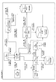
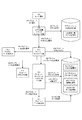
図1は、本発明の実施形態に係わる情報処理装置100の機能構成、および各機能の呼び出し関係を示す図である。図1において、ユーザ操作(101)は、GUI(グラフィカル・ユーザ・インタフェース)における定義画面(プログラム自動生成ツールにおいてプログラムの定義を行う画面)から行われる。具体的には、情報処理装置100にて動作しているプログラム自動生成ソフトにおけるGUIレイアウトタブ(図3)、項目一覧タブ(図4)でGUIレイアウト、または項目一覧の定義を行うが、タブの相互切り替えに際しての処理に関連するソフトウェア構成部品と、構成部品間の要求の図である。なお、GUIレイアウトタブおよび項目一覧タブに定義されている情報は、定義画面ヘッダの定義ファイル名(図3、図4の画面例では“USERREQ.wprx”)、あるいは当該画面を一意的に決定する情報により特定される。 FIG. 1 is a diagram showing a functional configuration of the information processing apparatus 100 according to the embodiment of the present invention and a calling relationship of each function. In FIG. 1, the user operation (101) is performed from a definition screen (a screen for defining a program in the automatic program generation tool) in the GUI (graphical user interface). Specifically, the GUI layout or the item list is defined on the GUI layout tab (Fig. 3) and the item list tab (Fig. 4) in the automatic program generation software running on the information processing device 100. It is a figure of the software component which is related to the process at the time of mutual switching, and the requirement between the component. The information defined in the GUI layout tab and the item list tab uniquely determines the definition file name of the definition screen header (“USEREQU.wprx” in the screen examples of FIGS. 3 and 4) or the screen. Identified by information.
ユーザ操作(101)により、項目一覧タブ選択要求121が、入出力定義エディタコントローラ部102に通知されると、入出力定義エディタコントローラ部102は、項目一覧モデル変換部103にレイアウトモデル変換要求122を通知する。
When the item list tab selection request 121 is notified to the input / output definition
項目一覧モデル変換部103は、GUIレイアウト定義を項目一覧定義に変換するため、現在のGUIレイアウト定義(GUIレイアウトタブで定義されたレイアウト定義でありレイアウト部品情報の定義の一覧)をレイアウトモデル記憶部107から取得する(レイアウトモデル変換時取得要求123)。さらに、項目一覧モデル変換部103は、取得した現在のGUIレイアウトを、項目一覧定義(項目情報の定義の一覧)に変換し、変換結果を項目一覧モデル記憶部104に登録する(既にある場合は更新する。項目一覧モデル更新要求124)。
In order to convert the GUI layout definition into the item list definition, the item list
入出力定義エディタコントローラ部102は、項目一覧定義の登録または更新後、当該登録または更新結果を取得する(項目一覧モデル表示時取得要求125)。入出力定義エディタコントローラ部102は、取得した項目一覧定義を項目一覧タブに表示するよう項目一覧表示部105に要求し、項目一覧表示部105は要求に従って項目一覧定義の表示を行う。
After registering or updating the item list definition, the input / output definition
ユーザ操作(101)により、レイアウトタブ選択要求141が、入出力定義エディタコントローラ部102に通知されると、入出力定義エディタコントローラ部102は、GUIレイアウトモデル変換部106に項目一覧モデル変換要求142を通知する。
When the layout tab selection request 141 is notified to the input / output definition
GUIレイアウトモデル変換部106は、項目一覧定義をGUIレイアウトモデル定義に変換するため、現在の項目一覧定義を項目一覧モデル記憶部104から取得する(項目一覧モデル変換時取得要求143)。さらに、GUIレイアウトモデル変換部106は、取得した現在の項目一覧定義を、GUIレイアウト定義に変換し、レイアウトモデル記憶部107に登録する(既にある場合は更新する。レイアウトモデル更新要求144)。
The GUI layout
入出力定義エディタコントローラ部102は、GUIレイアウト定義の登録または更新後、当該登録または更新結果を取得する(レイアウトモデル表示時取得要求145)。入出力定義エディタコントローラ部102は、取得したGUIレイアウト定義をGUIレイアウトタブに描画するための準備としてGUIレイアウトコントローラ部108にGUIレイアウト部品の生成を要求する(GUIレイアウト生成要求146)。
After registering or updating the GUI layout definition, the input / output definition
GUIレイアウト生成要求を受けたGUIレイアウトコントローラ部108は、レイアウトモデル記憶部107から取得したGUIレイアウト定義に基づき、描画するためのGUI部品などを生成する。まず、GUIレイアウト上のGUI部品(テキスト入力ボックスやボタンなど)を配置するためのベースとなる部品(ベース部品)を生成し、GUIレイアウト記憶部109(GUIレイアウト&部品記憶部)に追加する(GUIレイアウト追加要求147)。
The GUI
GUIレイアウトコントローラ部108は、さらにベース部品に配置するGUI部品を生成するため、ベース部品の直下のGUI部品ごとに、GUI部品生成要求148をGUI部品コントローラ部110に発行する。
The GUI
GUI部品コントローラ部110は、GUI部品生成要求148により要求されたGUI部品を、GUIレイアウト定義の個々の部品の定義(項目情報から変換された定義)に基づき生成する。GUIレイアウト定義において、GUI部品に入れ子のGUI部品(ベース部品の直下に配置される部品ではなく、GUI部品上に配置される子供となるGUI部品)が定義されている場合には、入れ子の部品を生成するようにGUI部品コントローラ部110に再帰的に要求を行う(GUI部品生成要求149)。生成したGUI部品は、GUIレイアウト記憶部109に追加する(GUI部品追加要求150)。
The GUI
GUIレイアウトコントローラ部108は、GUI部品(ベース部品を含む)の生成が完了すると、GUIレイアウト描画部111にGUIレイアウト描画要求151を発行する。この要求により、GUIレイアウト描画部111は、GUIレイアウトタブにGUIレイアウトの表示を行う。
When the generation of the GUI component (including the base component) is completed, the GUI
図2は、本発明の実施形態に係わる情報処理装置100(プログラム自動生成装置)のハードウェア構成の一例を示すブロック図である。 FIG. 2 is a block diagram showing an example of the hardware configuration of the information processing device 100 (program automatic generation device) according to the embodiment of the present invention.
図2に示すように、情報処理装置100は、システムバス204を介してCPU(Central Processing Unit)201、RAM(Random Access Memory)202、ROM(Read Only Memory)203、入力コントローラ205、ビデオコントローラ206、メモリコントローラ207、通信I/Fコントローラ208等が接続された構成を採る。 CPU201は、システムバス204に接続される各デバイスやコントローラを統括的に制御する。
As shown in FIG. 2, the information processing device 100 includes a CPU (Central Processing Unit) 201, a RAM (Random Access Memory) 202, a ROM (Read Only Memory) 203, an
また、ROM203あるいは外部メモリ211には、CPU201の制御プログラムであるBIOS(Basic Input/Output System)やOS(Operating System)や、各サーバあるいは各PCが実行する機能を実現するために必要な後述する各種プログラム等が記憶されている。また、本発明を実施するために必要な情報が記憶されている。なお外部メモリはデータベースであってもよい。
Further, the
RAM202は、CPU201の主メモリ、ワークエリア等として機能する。CPU201は、処理の実行に際して必要なプログラム等をROM203あるいは外部メモリ211からRAM202にロードし、ロードしたプログラムを実行することで各種動作を実現する。
The
また、入力コントローラ205は、キーボード(KB)209や不図示のマウス等のポインティングデバイス等からの入力を制御する。
Further, the
ビデオコントローラ206は、ディスプレイ210等の表示器への表示を制御する。尚、表示器は液晶ディスプレイ等の表示器でもよい。これらは、必要に応じて管理者が使用する。
The
メモリコントローラ207は、ブートプログラム、各種のアプリケーション、フォントデータ、ユーザファイル、編集ファイル、各種データ等を記憶する外部記憶装置(ハードディスク(HD))や、フレキシブルディスク(FD)、あるいは、PCMCIA(Personal Computer Memory Card International Association)カードスロットにアダプタを介して接続されるコンパクトフラッシュ(登録商標)メモリ等の外部メモリ211へのアクセスを制御する。
The
通信I/Fコントローラ208は、ネットワークを介して外部機器と接続・通信し、ネットワークでの通信制御処理を実行する。例えば、TCP/IP(Transmission Control Protocol/Internet Protocol)を用いた通信等が可能である。
The communication I /
尚、CPU201は、例えばRAM202内の表示情報用領域へアウトラインフォントの展開(ラスタライズ)処理を実行することにより、ディスプレイ210上に表示することが可能である。また、CPU201は、ディスプレイ210上のマウスカーソル(図示しない)等によるユーザ指示を可能とする。
The
本発明を実現するための後述する各種プログラムは、外部メモリ211に記録されており、必要に応じてRAM202にロードされることによりCPU201によって実行されるものである。さらに、上記プログラムの実行時に用いられる定義ファイルおよび各種情報テーブル等も、外部メモリ211に格納されており、これらについての詳細な説明についても後述する。
Various programs described later for realizing the present invention are recorded in the
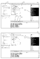
図3は、本発明の実施形態に係わるプログラム自動生成ツールのうちGUIレイアウトの定義を行う画面構成の一例である。GUIレイアウト定義画面は、主に次のエリアから構成されている。すなわち、定義された単位毎にフォルダ階層としてデータが格納される定義エクスプローラ領域301、1つのGUIレイアウト定義を視覚的に配置操作するためのキャンバス領域302、キャンバス領域302に配置するGUI部品(例えばテキストフィールド304)を選択するパレット領域303から構成されている。
FIG. 3 is an example of a screen configuration for defining a GUI layout among the automatic program generation tools according to the embodiment of the present invention. The GUI layout definition screen is mainly composed of the following areas. That is, the
また、開発者が様々な定義情報を記述するため、プログラム自動生成ツールの定義画面で共通に表示されるタブが配置されている。例えば、項目一覧タブ305、レイアウトタブ306であり、これらは図4の項目一覧定義画面でも表示される。本発明の実施形態では、GUIレイアウト定義画面(図3)と項目一覧定義画面(図4)を切り替えながら操作する。
In addition, tabs that are commonly displayed on the definition screen of the automatic program generation tool are arranged so that developers can describe various definition information. For example, there are an
また、本発明の実施形態では、定義エクスプローラ領域301にあるデータモデル308をパレット領域303のGUI部品と同様に、キャンバス領域302に配置することが可能である。すなわち、データモデル308から、データベースのテーブルに記載されたデータ項目(カラム)を1つまたは複数選択し、キャンバス領域302に配置する。そうすると、データベースのスキーマとして定義されたデータ項目(カラム)の情報(カラム名、データ種別、サイズなど)を抽出して、例えば、データ種別がテキストや数値である場合にはテキストフィールド、booleanである場合にはチェックボックスなどとして配置することができる。
Further, in the embodiment of the present invention, the
GUIレイアウト定義画面300bは、GUIレイアウト定義画面300aに対してテキストフィールド307を1つ追加し、名前を“ユーザID”と設定した場合を示している。タイトルや入力領域のサイズなどは、キャンバス領域302においてマウスでクリックして更新可能状態として交信してもよいし、またGUI部品をクリックする際に、GUIレイアウト定義画面300の左下の領域(“Property”定義領域)に、属性としてGUI部品に関連する情報の一覧を表示し、属性をキーボード入力により修正することも可能である。
The GUI
図4は、本発明の実施形態に係わるプログラム自動生成ツールのうち項目一覧の定義を行う画面構成の一例である。項目一覧定義画面は、主張な領域は、項目一覧設定領域401である。 FIG. 4 is an example of a screen configuration for defining an item list among the program automatic generation tools according to the embodiment of the present invention. In the item list definition screen, the asserting area is the item list setting area 401.
項目一覧設定領域401は表形式になっており、開発者は1行に1つの情報(例えばGUIレイアウトにおけるテキストフィールド、チェックボックス、ボタン、テキスト)などを詳細の属性と共に定義する。 The item list setting area 401 is in a tabular format, and the developer defines one piece of information per line (for example, a text field, a check box, a button, and a text in the GUI layout) together with detailed attributes.
項目一覧定義画面400bは、項目一覧定義画面400aに対して項目タイプ“入力”を1つ追加し、名前を“ユーザID”と設定した場合を示している(行402の定義)。行402の定義は、図3のテキストフィールド307に対応するものである。
The item
ここで、図3と図4の定義の関係を説明する。例えば図3のGUIレイアウト定義画面300aを表示しているときに、項目一覧タブ305を選択すると、表示は図4の項目一覧定義画面400aに切り替えられる。実質的に開発しているプログラムの同じ情報を定義している。図4において、前述の通り行402を追加して項目一覧定義画面400bとした後、レイアウトタブ306を選択すると、GUIレイアウト定義画面300bのようにレイアウト上でもテキストフィールド307が追加されて描画される。
Here, the relationship between the definitions of FIGS. 3 and 4 will be described. For example, if the
逆に、GUIレイアウト定義画面300aに対してレイアウト上でもテキストフィールド307を追加してGUIレイアウト定義画面300bとした後、項目一覧タブ305を選択すると、項目一覧定義画面400bのように項目一覧上でも行402の定義が追加される。
On the contrary, if the
すなわち、GUIレイアウト定義と項目一覧定義は、タブ(項目一覧タブ305およびレイアウトタブ306)の操作をトリガとして、同期がとられている。
That is, the GUI layout definition and the item list definition are synchronized with the operation of the tabs (
さらに、後述する図5の項目一覧定義を記憶するデータ構成rows[i]と、不図示のGUIレイアウト定義を記憶するデータ構成には、rowIndexとして各定義の定義順が記載されている。そのため、GUIレイアウト定義で最上部に定義されたGUI部品に対応する項目の定義は、項目一覧定義の1行目に表示される。これにより、定義の位置関係についても同期がとられ、いずれの定義を変更してもプログラムロジックとGUIレイアウトの関係が壊れてしまうことはない。 Further, in the data structure rows [i] for storing the item list definition of FIG. 5 to be described later and the data structure for storing the GUI layout definition (not shown), the definition order of each definition is described as rowIndex. Therefore, the definition of the item corresponding to the GUI component defined at the top in the GUI layout definition is displayed on the first line of the item list definition. As a result, the positional relationship of the definitions is also synchronized, and the relationship between the program logic and the GUI layout is not broken even if any definition is changed.
以上により、図3と図4の説明を完了する。このように、項目一覧における開発とGUIレイアウトにおける開発(すなわち項目の定義も部品の定義)において同期がとられることで、開発中のどのタイミングでもGUIレイアウトを確認可能とし、またプログラムロジックとGUIレイアウトのいずれを編集したとしても対応関係を修正する必要をなくすることにより、開発効率を向上させることが可能となるという効果を得ることができる。 This completes the description of FIGS. 3 and 4. In this way, by synchronizing the development in the item list and the development in the GUI layout (that is, the definition of the item is also the definition of the part), the GUI layout can be confirmed at any time during development, and the program logic and GUI layout can be confirmed. Regardless of which of the above is edited, it is possible to obtain the effect that the development efficiency can be improved by eliminating the need to modify the correspondence.
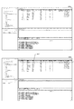
図5は、本発明の実施形態に係わるプログラム自動生成ツールで定義された項目一覧の情報を記憶する項目一覧モデル記憶部におけるデータ構成の一例を示す図である。記載したデータは、図4の項目一覧定義画面400の項目一覧設定領域401において定義した行のうち、例として5行を記載したものである。この情報は、RAM202上に一時的に記憶されていてもよいし、データベースに記憶してもよい。以下、RAM202に記憶されているイメージで説明する。
FIG. 5 is a diagram showing an example of a data structure in the item list model storage unit that stores the item list information defined by the program automatic generation tool according to the embodiment of the present invention. The described data describes 5 lines as an example among the lines defined in the item list setting area 401 of the item list definition screen 400 of FIG. This information may be temporarily stored in the
項目一覧定義は配列rowsの各項目定義は、rows[0]〜rows[4]に格納されている。rows[i](各要素)は、図5示すようにdataという要素を持ち、複数の属性値、例えば入力欄を示す“I”、項目IDを示す“USERID”、項目の名前を示す“ユーザID”などが設定される。 Item list definition is an array rows Each item definition is stored in rows [0] to rows [4]. Rows [i] (each element) has an element called data as shown in FIG. 5, and has a plurality of attribute values, for example, "I" indicating an input field, "USERID" indicating an item ID, and "user" indicating an item name. ID "etc. are set.
さらに、プログラム自動生成に使用される各種属性が定義されている。また、“owPropertyList”には、名前を表示する領域のサイズ“labelWidth”、テキスト入力欄の領域サイズ“fieldWidth”などが指定される。 In addition, various attributes used for automatic program generation are defined. In addition, the size of the area for displaying the name "labelWith", the area size of the text input field "fieldWith", and the like are specified in "owPropertyList".
以上で、項目一覧モデル記憶部104におけるデータ構成の説明を完了する。さらに、不図示ではあるが、図3のGUIレイアウトについても、レイアウトモデル記憶部107に記憶される。両者のデータ構成はほぼ同一のものである。本発明の実施形態では、項目一覧モデル記憶部104に記憶された情報を中心とするため、レイアウトモデル記憶部107におけるデータ構成は、各要素(レイアウト部品情報)が、対応する項目情報へのリンクを有すること、また項目情報(rows[i])における領域サイズの情報は、HTMLに変換した際のサイズを示すが、レイアウト部品譲歩においては、GUIレイアウト定義画面300のキャンバス領域302に表示する際に適したサイズに変換されている、など一部の情報が異なる。項目一覧モデル記憶部104、レイアウトモデル記憶部107のデータ構成はあくまで一例であって、他の構成の形式で定義されていてもよい。
This completes the description of the data structure in the item list
図6は、本発明の実施形態に係わるGUIレイアウトの定義を項目一覧の定義に同期するためのシーケンス図の一例である。図6のシーケンス図の各ステップは、情報処理装置100のCPU201により実行される。
FIG. 6 is an example of a sequence diagram for synchronizing the definition of the GUI layout according to the embodiment of the present invention with the definition of the item list. Each step of the sequence diagram of FIG. 6 is executed by the
S601において、ユーザ操作(101)により項目一覧タブが選択された際に、プログラム開発ツールから項目一覧タブ選択の要求が発行され、入出力定義エディタコントローラ部102が、定義画面を項目一覧タブ(図4)に切り替えるための要求を受け付ける(項目一覧タブ選択要求121)。
In S601, when the item list tab is selected by the user operation (101), the program development tool issues a request for selecting the item list tab, and the input / output definition
S602において、入出力定義エディタコントローラ部102が、GUIレイアウト定義を項目一覧定義に変換するように、項目一覧モデル変換部103に要求する(レイアウトモデル変換要求122)。ここで、いずれの定義に対する変換を要求するかは、図1で説明したとおり定義を一意的に決定する情報により特定される。
In S602, the input / output definition
S603において、項目一覧モデル変換部103が、GUIレイアウトの定義をレイアウトモデル記憶部107から取得する(レイアウトモデル変換時取得要求123)。
In S603, the item list
S604において、項目一覧モデル変換部103は、更に取得したGUIレイアウトを項目一覧定義に変換する。前述したように、GUIレイアウト定義では、GUIレイアウト定義画面300のキャンバス領域302に表示する際に適したサイズを保持しているため、それらのサイズをプログラム自動生成時に、HTMLの部品として生成するために適切なサイズに変換する、などの変換処理を行う。
In S604, the item list
S605において、項目一覧モデル変換部103は、取得した現在のGUIレイアウトを、項目一覧定義(項目情報の定義の一覧)に変換し、変換結果を項目一覧モデル記憶部104に登録する(既にある場合は更新する。項目一覧モデル更新要求124)。
In S605, the item list
S606において、入出力定義エディタコントローラ部102は、登録または更新された項目一覧定義を、項目一覧モデル記憶部104から取得する(項目一覧モデル表示時取得要求125)。
In S606, the input / output definition
S607において、入出力定義エディタコントローラ部102は、取得した項目一覧定義を項目一覧タブに表示するよう項目一覧表示部105に要求し、項目一覧表示部105は要求に従って項目一覧定義の表示を行う。
In S607, the input / output definition
図7は、本発明の実施形態に係わる項目一覧の定義をGUIレイアウトの定義に同期するためのシーケンス図の一例である。図6のシーケンス図の各ステップは、情報処理装置100のCPU201により実行される。
FIG. 7 is an example of a sequence diagram for synchronizing the definition of the item list according to the embodiment of the present invention with the definition of the GUI layout. Each step of the sequence diagram of FIG. 6 is executed by the
S701において、ユーザ操作(101)によりレイアウトタブが選択された際に、プログラム開発ツールからレイアウトタブ選択の要求が発行され、入出力定義エディタコントローラ部102が、定義画面をレイアウト定義タブ(図3)に切り替えるための要求を受け付ける(レイアウトタブ選択要求141)。
In S701, when the layout tab is selected by the user operation (101), the program development tool issues a request for selecting the layout tab, and the input / output definition
S702において、入出力定義エディタコントローラ部102は、GUIレイアウトモデル変換部106に項目一覧モデル変換要求142を通知する(項目一覧モデル変換要求142)。ここで、いずれの定義に対する変換を要求するかは、図1で説明したとおり定義を一意的に決定する情報により特定される。
In S702, the input / output definition
S703において、GUIレイアウトモデル変換部106は、項目一覧定義をGUIレイアウトモデル定義に変換するため、現在の項目一覧定義を項目一覧モデル記憶部104から取得する(項目一覧モデル変換時取得要求143)。
In S703, the GUI layout
S704において、GUIレイアウトモデル変換部106は、取得した現在の項目一覧定義を、GUIレイアウト定義に変換する。
In S704, the GUI layout
S705において、GUIレイアウトモデル変換部106は、変換したGUIレイアウト定義をレイアウトモデル記憶部107に登録する(既にある場合は更新する。レイアウトモデル更新要求144)。
In S705, the GUI layout
S706において、入出力定義エディタコントローラ部102は、GUIレイアウト定義の登録または更新後、当該登録または更新結果を取得する(レイアウトモデル表示時取得要求145)。
In S706, the input / output definition
S707において、入出力定義エディタコントローラ部102は、取得したGUIレイアウト定義をGUIレイアウトタブに描画するための準備としてGUIレイアウトコントローラ部108にGUIレイアウト部品の生成を要求する(GUIレイアウト生成要求146)。
In S707, the input / output definition
S708において、GUIレイアウト生成要求を受けたGUIレイアウトコントローラ部108は、レイアウトモデル記憶部107から取得したGUIレイアウト定義に基づき、描画するためのGUI部品などを生成する。まず、GUIレイアウト上のGUI部品(テキスト入力ボックスやボタンなど)を配置するためのベースとなる部品(ベース部品)を生成し、GUIレイアウト記憶部109(GUIレイアウト&部品記憶部)に追加する(GUIレイアウト追加要求147)。
In S708, the GUI
S709において、GUIレイアウトコントローラ部108は、さらにベース部品に配置するGUI部品を生成するため、ベース部品の直下のGUI部品ごとに、GUI部品生成要求148をGUI部品コントローラ部110に発行する。
In S709, the GUI
S710において、GUI部品コントローラ部110は、GUI部品生成要求148により要求されたGUI部品を、GUIレイアウト定義の個々の部品の定義(項目情報から変換された定義)に基づき生成する。GUIレイアウト定義において、GUI部品に入れ子のGUI部品(ベース部品の直下に配置される部品ではなく、GUI部品上に配置される子供となるGUI部品)が定義されている場合には、入れ子の部品を生成するようにGUI部品コントローラ部110に再帰的に要求を行う(GUI部品生成要求149)。生成したGUI部品は、GUIレイアウト記憶部109に追加する(GUI部品追加要求150)。
In S710, the GUI
S711において、GUIレイアウトコントローラ部108は、GUI部品(ベース部品を含む)の生成が完了すると、GUIレイアウト描画部111にGUIレイアウト描画要求151を発行する。この要求により、GUIレイアウト描画部111は、GUIレイアウトタブにGUIレイアウトの表示を行う。
In S711, the GUI
図6と図7のシーケンス図で説明したとおり、項目一覧タブとレイアウトタブを切り替えるユーザの操作をトリガとして、両者に表示されるデータ(項目一覧定義とGUIレイアウト定義)が再生成され、項目一覧定義(プログラムロジック)と、GUIレイアウト定義(HTML生成などのための画面情報)を、手動で対応付けるための操作や、対応情報の作成などを行う必要がなくなる。これにより、プログラム自動生成ツールによるプログラム定義の作業の生産性が向上するという効果が得られる。 As described in the sequence diagrams of FIGS. 6 and 7, the data (item list definition and GUI layout definition) displayed on both of them is regenerated by the user's operation of switching between the item list tab and the layout tab, and the item list is displayed. There is no need to manually associate the definition (program logic) with the GUI layout definition (screen information for HTML generation, etc.) or create correspondence information. This has the effect of improving the productivity of the program definition work by the automatic program generation tool.
次に、図8〜図12を用いて、プレビューHTML生成についての詳細な説明を行う。プレビューHTMLは、アプリケーションにいて、ビジネスロジック(コントローラ)、データベースモデルに対応するビューであるHTMLを、プレビューとして開発途中に生成し確認するためのHTML画面である。 Next, the preview HTML generation will be described in detail with reference to FIGS. 8 to 12. The preview HTML is an HTML screen for generating and confirming HTML, which is a view corresponding to the business logic (controller) and the database model, as a preview during development in the application.
図8は、本発明の実施形態に係わる情報処理装置のプレビューに関する機能構成、および各機能の呼び出し関係を示す図の一例である。また、図8では、各機能部や要求の概略だけを説明し、詳細は図12のフローチャートで説明する。 FIG. 8 is an example of a diagram showing a functional configuration related to a preview of the information processing apparatus according to the embodiment of the present invention and a calling relationship of each function. Further, in FIG. 8, only the outline of each functional unit and the requirement will be described, and the details will be described with reference to the flowchart of FIG.
まず、ユーザ操作(101)は、図1で説明したとおり、GUI(グラフィカル・ユーザ・インタフェース)における定義画面(プログラム自動生成ツールにおいてプログラムの定義を行う画面)から行われる。 First, the user operation (101) is performed from the definition screen (the screen for defining the program in the automatic program generation tool) in the GUI (graphical user interface) as described with reference to FIG.
具体的には、情報処理装置100にて動作しているプログラム自動生成ソフトにおけるGUIレイアウトタブ(図3)、項目一覧タブ(図4)で操作が行われる。プレビューHTML生成については、図3のプレビュータブ309をユーザが操作したタイミング(プレビュータブ選択831)で、当該操作のイベントが、入出力定義エディタコントローラ部102に通知される。
Specifically, the operation is performed on the GUI layout tab (FIG. 3) and the item list tab (FIG. 4) in the automatic program generation software operating in the information processing apparatus 100. Regarding the preview HTML generation, the event of the operation is notified to the input / output definition
入出力定義エディタコントローラ部102は、アプリケーション定義体記憶部のうち、処理に必要な項目一覧情報を取得する(入出力モデル取得832)。具体的には、プレビューHTML生成に必要な情報を項目一覧モデル記憶部104から取得する。言わば表示情報のフィルタリングを行う。ここで、図11を用いて、取得した項目一覧情報について説明する。
The input / output definition
図11は、本発明の実施形態に係わるプレビューHTMLを生成するために必要な定義情報をアプリケーション定義から取得した結果のデータ構成を示す図の一例である。データ構造としては図5で説明した“rows”とほぼ同様である。まず、開発中のアプリケーションを定義するデータとしては、ビジネスロジックの定義体、データベースモデルの定義体、その他アプリケーションの各種プロパティを定義体など、多くの定義体がある。入出力定義であっても、現在、プレビューHTMLを生成しようとしている入出力定義体と、それ以外の定義体がある。 FIG. 11 is an example of a diagram showing a data structure as a result of acquiring definition information necessary for generating preview HTML according to an embodiment of the present invention from an application definition. The data structure is almost the same as the “rows” described in FIG. First, as data that defines an application under development, there are many definition programs such as a business logic definition program, a database model definition program, and other application property definitions. Even for input / output definitions, there are input / output definitions that are currently trying to generate preview HTML and other definitions.
入出力定義エディタコントローラ部102は、まず必要な定義体のみを選択する。具体的には、例えば、図4の項目一覧定義が記載されているデータを含む定義体である。なお、ここで「定義体」という文言は便宜上用いている。実際には、1つの定義体が1ファイルに格納されていても良い。あるいは、1つのアプリケーション全体に関する定義体が1つのファイルに格納され、それぞれの(例えば1つの項目一覧)定義は、タグで判別可能としても良い。この場合は、当該タグの内容を意味する。また、開発中はファイルに格納されておらず、RAM202上にデータが展開されている、あるいはファイルではなくデータベースに格納されていても良い。従って、定義体という文言は、ここでは、1つの項目一覧情報を他の定義情報から区別するための便宜上の用語として使用する。
The input / output definition
1つの項目一覧情報を取得したものは、図5のrows500あるいは同等の情報を持つデータ構造で実装される定義体となる。さらに、図4の項目一覧定義においては、“少数”〜“データモデル項目コード”などはHTML画面の情報としては不要である。これらは、データベースとの連携を定義するものなどである。そこで、不要な列の削除を行う。図5のrows500で説明すると、例えば2行目の“−1”〜“@TEXT”などが不要になるので削除する。これらの処理の結果として、図11のfilteredRows1100が取得される。
The one that has acquired one item list information is a definition program implemented in the
ここで、画面情報(ビュー)に関連したビジネスロジック、データベースモデルなどが完成していない段階であっても、プレビューHTMLを生成することが可能であるので、柔軟なタイミングで画面を確認し、効率的な開発を進めるという効果を得ることが可能となる。また、プレビューHTML生成のために必要な情報を用いることで、アプリケーション全体をビルドしなくても画面イメージを確認できることにより、ビルド時間の効率化を得ることができる。 Here, even if the business logic, database model, etc. related to the screen information (view) are not completed, it is possible to generate the preview HTML, so the screen can be checked at a flexible timing and efficiency is achieved. It is possible to obtain the effect of advancing the development. Further, by using the information necessary for generating the preview HTML, the screen image can be confirmed without building the entire application, so that the efficiency of the build time can be obtained.
項目一覧情報の取得後、入出力定義エディタコントローラ部102は、プレビューコントローラ部811にプレビューHTML生成要求833を行う。
After acquiring the item list information, the input / output definition
概略として“プレビューテンプレート”という文言を説明すると“プレビューテンプレート”は、項目一覧情報からHTMLのタグの階層構造にマッピングを行うことが可能な、簡易言語であり、プレビューHTML生成部814に保持されている。プレビューテンプレートパラメータ生成部812は、プレビューHTML生成部814に渡すためのプレビューテンプレートパラメータを生成する。
To explain the word "preview template" as a summary, the "preview template" is a simple language that can map the item list information to the hierarchical structure of HTML tags, and is held in the preview
入出力定義エディタコントローラ部102は、まず、プレビューHTMLファイルを生成した後で格納するフルパス名を生成する。ファイル名は、予めユーザにより、プレビューHTML名記憶部821に定義し、プレビューHTML名取得834により取得する。
The input / output definition
図10は、本発明の実施形態に係わるプレビューHTMLのファイル保管場所(フォルダ)を指定するユーザ画面を示す図の一例である。このダイアログを表示し、ユーザにHTMLファイルを格納するフォルダ名を入力させる。前記取得したファイル名と合わせ、ファイルのフルパス名が決定する。 FIG. 10 is an example of a diagram showing a user screen for designating a file storage location (folder) of the preview HTML according to the embodiment of the present invention. Display this dialog and ask the user to enter the name of the folder that stores the HTML file. The full path name of the file is determined together with the acquired file name.
さらに、プレビューHTMLを生成するための情報を取得し、データ構成を生成するために、プレビューテンプレートパラメータ生成部812にプレビューテンプレートパラメータ生成要求835を行う。
Further, in order to acquire the information for generating the preview HTML and generate the data structure, the preview template
プレビューテンプレートパラメータ生成部812は、プレビューHTMLの生成に必要な情報であるプレビュープロパティを、プレビュープロパティ記憶部822から取得する(プレビュープロパティ取得836。プロパティの詳細については後述する)。さらにスタイル情報をスタイル情報記憶部823から取得する(スタイル情報取得837。スタイル情報は、HTMLのスタイルシートなどの情報であり、詳細は後述する)。
The preview template
図9は、本発明の実施形態に係わるプレビューHTMLのプレビュー状態を示す図の一例である。プレビューHTMLタブ900bでは、902にプロパティコードが設定されており、そのプロパティコードに従って、903の各プロパティが読み出され、プレビューHTMLが生成される。プレビューHTMLタブ900aでは、デフォルトのプロパティコード(不図示)を設定している。プレビューHTMLタブ900bのプロパティ903で指定される項目には、例えば“ロール”、(拡張ディレクトリ/)“言語”がある(図9の例には更に“表示データディレクトリ”があるが後述)。
FIG. 9 is an example of a diagram showing a preview state of the preview HTML according to the embodiment of the present invention. In the
例えば、“ロール”とは、組織の中の役割(役職や職種)を示すプロパティである。アプリケーションでは、本来同一である画面でも、役職などによって表示する項目の制御をすることがある。従って、プレビューHTMLの生成においても、ロールプロパティを設定することで、当該設定に応じた表示する項目の制御を行い、すなわち、同一の項目一覧定義からであっても、ロールによって異なる画面のプレビューHTMLを生成することを可能にするという効果を得られる。 For example, a "role" is a property that indicates a role (position or occupation) in an organization. In the application, even if the screen is originally the same, the items to be displayed may be controlled depending on the job title or the like. Therefore, even in the generation of the preview HTML, the items to be displayed are controlled according to the setting by setting the role property, that is, the preview HTML of the screen different depending on the role even from the same item list definition. You can get the effect of making it possible to generate.
また、(拡張ディレクトリ/)“言語”がある。言語プロパティについては、プログラム自動生成ツールが、英語/日本語などの複数の言語に対応している場合に、いずれの言語でプレビューHTML画面を生成するかを指定するものである。 There is also a (extended directory /) "language". Regarding the language property, when the program automatic generation tool supports a plurality of languages such as English / Japanese, which language is used to generate the preview HTML screen is specified.
更に、スタイル情報取得837により、スタイル情報記憶部823から、プレビューHTMLで使用するスタイルシートを取得する。スタイルシートには、ユーザ(開発者)が柔軟に変更可能な部分と、アプリケーション(あるいは、アプリケーション開発を管理するプロジェクト)で固定の部分があっても良い。例えば、文字サイズ、フォント、背景色、線の太さなどの定義である。 Further, the style information acquisition 837 acquires the style sheet used in the preview HTML from the style information storage unit 823. The style sheet may have a part that can be flexibly changed by the user (developer) and a fixed part in the application (or the project that manages the application development). For example, definitions such as character size, font, background color, and line thickness.
以上で、HTMLを生成するためのオブジェクト(入出力フィールド、ボタンなど)の情報は、HTMLの階層構造を反映する階層的なデータ構成、あるいは階層的なデータ構成と置換可能なデータ構成として格納されている。便宜上、前者の「HTMLの階層構造を反映する階層的なデータ構成」を前提として説明を継続するが、いずれの形式であっても、最終的にHTMLに変換可能である、同等の情報を持ったデータ構成であればよい。また、前記データ構造は、オブジェクトの配置や名称(例えば、テキストボックスの配置や「ユーザ名」などのタイトル)は情報として含んでいるが、実際の値(例えばユーザ名が「鈴木一郎」などの値)は含んでいないため、以下の説明では便宜上「プレビューテンプレート」と呼ぶことにする(前述の「テンプレート」と同一のもの)。しかしながら、「プレビューテンプレート」は、値(例では「ユーザ名」フィールドに対応する「鈴木一郎」)をどこに代入すればよいか、という情報は、プレビューテンプレートにパラメータ(あるいは変数)として含まれているものとする。 As described above, the information of the objects (input / output fields, buttons, etc.) for generating the HTML is stored as a hierarchical data structure that reflects the hierarchical structure of the HTML, or a data structure that can be replaced with the hierarchical data structure. ing. For convenience, the explanation will be continued on the premise of the former "hierarchical data structure that reflects the hierarchical structure of HTML", but any format has equivalent information that can be finally converted to HTML. Any data structure will do. Further, the data structure includes the arrangement and name of the object (for example, the arrangement of the text box and the title such as "user name") as information, but the actual value (for example, the user name is "Ichiro Suzuki") is included. Since the value) is not included, it will be referred to as a "preview template" for convenience in the following description (the same as the "template" described above). However, the information about where to assign the value (in the example, "Ichiro Suzuki" corresponding to the "Username" field) in the "Preview template" is included as a parameter (or variable) in the preview template. It shall be.
HTML画面用に定義した項目一覧を、前述のようなHTMLに変換可能な形式に格納し、後述するHTMLに実際に変換することは、プログラム自動生成ツールなどで周知の技術であるため詳細の説明は省略する。 The item list defined for the HTML screen is stored in a format that can be converted to HTML as described above, and the actual conversion to HTML described later is a well-known technique in a program automatic generation tool or the like, so a detailed explanation will be given. Is omitted.
プレビューテンプレートパラメータ生成部812は、プレビューデータ設定部813に対して、前述の「プレビューテンプレート」にサンプルの値を代入するための、プレビューデータ設定要求838を行う。プレビューデータ設定部813は、代入値データ記憶部824からデータを取得(代入値データ取得839)し、「プレビューテンプレートパラメータ」を作成する。
The preview template
これらの処理結果は、プレビューコントローラ部811に返され、プレビューコントローラ部811は、「プレビューテンプレートパラメータ」に基づきプレビューHTMLを生成するようプレビューHTML生成部814に要求(テンプレートHTML変換要求840)する。要求を受けた、841プレビューHTML生成部は保持するプレビューテンプレートとプレビューテンプレートパラメータをマッピングし、プレビューHTMLを生成する。更に、プレビューHTML表示要求841により、情報処理装置100の表示装置(開発ツールのプレビュータブ)にプレビューHTMLを表示する(図9の画面)。
These processing results are returned to the
前述の説明では、代入値データ記憶部824により「値が入ったプレビューテンプレートパラメータ」が作成される、と説明したが、プレビューHTMLタブ900aにおいては、「XXXX・・・」などの意味のない値が表示されている(901a)。これは、代入値データ記憶部824に代入するための情報が定義されているか、による。
In the above explanation, it has been explained that the "preview template parameter containing the value" is created by the substitution value data storage unit 824, but in the
具体的には、プロパティ903の“表示データディレクトリ”にフォルダが記載されていない、あるいは記載されていても(例では“C:¥PreviewData”)、そのフォルダ内にデータが格納されていない場合に、デフォルトとしてプレビューHTMLタブ900aの画面が表示される。これらのデフォルト値は、プログラム中にハードコーディングされていても良いし、デフォルト値記憶部(不図示)に保存されていても良い。デフォルト値であっても、例えば入力フィールドのタイプ(全角文字、半角英数字など)により、複数種類用意されていても良い。この場合、項目一覧定義体の各要素において、入力フィールドの定義が明示されている場合にはそのタイプに従う。
Specifically, when the folder is not described in the "display data directory" of the
一方、代入値データ記憶部824に代入するための値(例えばCSVファイルなどで用意する)がある場合には、プレビューHTMLタブ900bのように、ユーザに分かりやすい(人間にとって意味のある)値を表示させることが可能である(901b)。
On the other hand, if there is a value to be assigned to the substitution value data storage unit 824 (for example, prepared in a CSV file), a value that is easy for the user to understand (meaningful to humans), such as the
以上で、図8のプレビューHTML生成のための機能構成および各機能の呼び出し関係の説明を完了する。あわせて、図9〜図11の説明も完了する。 This completes the description of the function configuration for generating the preview HTML of FIG. 8 and the calling relationship of each function. At the same time, the description of FIGS. 9 to 11 is completed.
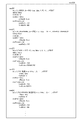
図12は、本発明の実施形態に係わるプレビューHTMLの生成処理を示すフローチャートの一例である。図12のフローチャートの各ステップは、情報処理装置100のCPU201により実行される。なお、機能構成図(図8)の説明において述べた部分については、具体的な詳細事項の説明を省略する場合がある。
FIG. 12 is an example of a flowchart showing a preview HTML generation process according to the embodiment of the present invention. Each step of the flowchart of FIG. 12 is executed by the
S1201においては、ユーザ操作(101)を、GUI(グラフィカル・ユーザ・インタフェース)における定義画面(プログラム自動生成ツールにおいてプログラムの定義を行う画面)から受け付ける。具体的には、情報処理装置100にて動作しているプログラム自動生成ソフトにおいて、ユーザがプレビュータブ309を選択したイベントを受け付ける。
In S1201, the user operation (101) is received from the definition screen (the screen for defining the program in the automatic program generation tool) in the GUI (graphical user interface). Specifically, in the program automatic generation software operating in the information processing apparatus 100, an event in which the user selects the
S1202からS1205の繰り返し処理においては、アプリケーション定義情報の全ての定義体から、プレビュー表示要求対象の画面に関連する情報を取得する。
S1203においては、アプリケーション定義体記憶部から取得する。
In the iterative process of S1202 to S1205, information related to the screen of the preview display request target is acquired from all the definition programs of the application definition information.
In S1203, it is acquired from the application definition program storage unit.
S1204においては、S1203で取得した定義体が、プレビュー表示要求対象の項目一覧の定義体であるか判定し、そうであれば繰り返し処理(S1202〜S1205)を抜ける。具体的には、当該定義体が、項目一覧モデル記憶部104から取得したものであり、更に、現在定義中(開発中)の項目一覧定義の定義体であるものを取得する。
In S1204, it is determined whether the definition program acquired in S1203 is the definition program of the item list of the preview display request target, and if so, the iterative process (S1202 to S1205) is exited. Specifically, the definition program is acquired from the item list
次に、S1206からS1209の繰り返し処理においては、前述で取得した項目一覧の定義体(例えば図5のrows500)から、要素を1つずつ取り出し、全ての要素に対して以下の処理を実行する。
Next, in the iterative processing of S1206 to S1209, elements are taken out one by one from the item list definition program (for example,
S1207においては、項目一覧の定義体(例えば図5のrows500)から、要素(row[i])を1つずつ取り出し、前述したとおり、図4の項目一覧定義における“少数”〜“データモデル項目コード”などHTML画面の情報としては不要な部分を除き、“項目タイプ”、“項目コード”〜“桁数”(図4参照)など、HTML画面のオブジェクトとして必要な情報を抽出する。
In S1207, elements (row [i]) are extracted one by one from the item list definition program (for example,
S1208においては、S1207で抽出した情報を、filteredRows1100に格納する(要素filteredRows[i])。このように、プレビューHTML生成においては、プログラム自動生成ツールで定義した定義体のうち、プレビューHTML生成に必要な情報のみを利用することで、ビジネスロジック、データベースモデルなどが完成していない段階であっても、プレビューHTMLを生成することが可能であり、柔軟なタイミングで画面を確認し、効率的な開発を進めるという効果を得ることが可能となる。また、プレビューHTML生成のために必要な情報を用いることで、アプリケーション全体をビルドしなくても画面イメージを確認できることにより、ビルド時間の効率化を得ることができる。 In S1208, the information extracted in S1207 is stored in the filtered Rows 1100 (element filtered Rows [i]). In this way, in the preview HTML generation, the business logic, database model, etc. are not completed by using only the information necessary for the preview HTML generation among the definition programs defined by the program automatic generation tool. However, it is possible to generate preview HTML, and it is possible to obtain the effect of confirming the screen at a flexible timing and advancing efficient development. Further, by using the information necessary for generating the preview HTML, the screen image can be confirmed without building the entire application, so that the efficiency of the build time can be obtained.
S1210においては、プレビューテンプレートを生成し、生成するプレビューHTMLファイルの名前を取得し、プレビューテンプレートに格納する。ここでプレビューテンプレートとは、前述したとおり、HTMLの構造を生成する直前の段階のデータ構成である。即ち、プレビューテンプレートは、HTMLのタグの階層構造にマッピングを行うことで、実際のHTMLを生成可能な情報を含むものである。 In S1210, a preview template is generated, the name of the generated preview HTML file is acquired, and the name is stored in the preview template. Here, the preview template is, as described above, the data structure at the stage immediately before the HTML structure is generated. That is, the preview template includes information that can generate an actual HTML by mapping to the hierarchical structure of HTML tags.
S1211においては、生成するプレビューHTMLファイルのプレビュープロパティを取得し、プレビューテンプレートに格納する。具体的には、図9の903において説明した。 In S1211, the preview property of the generated preview HTML file is acquired and stored in the preview template. Specifically, it was described with reference to 903 of FIG.
S1212は、プレビューHTMLのスタイル情報を取得する。具体的には、スタイルシートの情報である。 S1212 acquires the style information of the preview HTML. Specifically, it is the information of the style sheet.
S1213からS1215の繰り返し処理は、filteredRows1100の全要素に対して実行される。 The iterative process of S1213 to S1215 is executed for all the elements of the filtered Rows 1100.
S1214においては、filteredRows[i](項目一覧定義の1要素からHMTLの1オブジェクトに対応する表示に必要な情報を取り出したデータ)を、プレビューテンプレートに埋め込んでいく。ただし、S1214の処理が実行されるのは、“ロール”プロパティにより、表示すべきと判断されたfilteredRows[i]のみである。これにより、実質的にはプレビューHTMLと等価なデータ構造ができあがる。この段階で、フィールド部品に表示するユーザデータには値は入っていない。 In S1214, filtered Rows [i] (data obtained by extracting information necessary for display corresponding to one object of HMTL from one element of the item list definition) is embedded in the preview template. However, the process of S1214 is executed only for the filtered Rows [i] determined to be displayed by the "role" property. As a result, a data structure substantially equivalent to the preview HTML is completed. At this stage, there is no value in the user data displayed in the field part.
S1216においては、フィールド部品に、具体的な値は入をいれていく。具体的な値は、代入値データ記憶部824から取得する。代入値データ記憶部824には、例えばCSV形式のファイルなどにより、例えばフィールドの項目名(あるいは項目ID)に対応付けて、その入力フィールドに挿入したい値が定義されている。この値を、前述のプレビューテンプレートの変数パと置き換えていく。 In S1216, a specific value is entered in the field component. The specific value is acquired from the substitution value data storage unit 824. In the substitution value data storage unit 824, for example, a value to be inserted into the input field is defined in association with the item name (or item ID) of the field by, for example, a CSV format file. Replace this value with the variable parameter of the preview template described above.
S1217においては、一覧項目の名、型、代入値を、HTMLオブジェクトに変換し、プレビューHTMLファイルに埋め込んでいく。 In S1217, the name, type, and assigned value of the list item are converted into HTML objects and embedded in the preview HTML file.
S1218においては、生成されたプレビューHTMLファイルを、情報処理装置100の表示装置(開発ツールのプレビュータブ)にプレビューHTMLを表示する(図9の画面)。
以上で、図12のフローチャートの説明を完了する。
In S1218, the generated preview HTML file is displayed on the display device (preview tab of the development tool) of the information processing device 100 (screen of FIG. 9).
This completes the description of the flowchart of FIG.
なお、上述した各種データの構成及びその内容はこれに限定されるものではなく、用途や目的に応じて、様々な構成や内容で構成されることは言うまでもない。 It should be noted that the structure and contents of the various data described above are not limited to this, and it goes without saying that the structure and contents are various depending on the intended use and purpose.
以上、一実施形態について示したが、本発明は、例えば、システム、装置、方法、プログラムもしくは記録媒体等としての実施態様をとることが可能であり、具体的には、複数の機器から構成されるシステムに適用しても良いし、また、一つの機器からなる装置に適用しても良い。 Although one embodiment has been described above, the present invention can take an embodiment as a system, an apparatus, a method, a program, a recording medium, or the like, and specifically, is composed of a plurality of devices. It may be applied to a system or a device consisting of one device.
また、本発明におけるプログラムは、図6、図7に示すシーケンス図、図12のフローチャートの処理方法をコンピュータが実行可能なプログラムであり、本発明の記憶媒体は図6、図7に示すシーケンス図、図12のフローチャートの処理方法をコンピュータが実行可能なプログラムが記憶されている。なお、本発明におけるプログラムは図6、図7、図12のフローチャートに示すシーケンス図の各装置の処理方法ごとのプログラムであってもよい。 Further, the program in the present invention is a program in which a computer can execute the processing methods of the sequence diagrams shown in FIGS. 6 and 7, and the flowchart of FIG. 12, and the storage medium of the present invention is the sequence diagram shown in FIGS. 6 and 7. , A program in which a computer can execute the processing method of the flowchart of FIG. 12 is stored. The program in the present invention may be a program for each processing method of each device in the sequence diagram shown in the flowcharts of FIGS. 6, 7, and 12.
以上のように、前述した実施形態の機能を実現するプログラムを記録した記録媒体を、システムあるいは装置に供給し、そのシステムあるいは装置のコンピュータ(またはCPUやMPU)が記録媒体に格納されたプログラムを読出し実行することによっても、本発明の目的が達成されることは言うまでもない。 As described above, the recording medium on which the program that realizes the functions of the above-described embodiment is recorded is supplied to the system or the device, and the computer (or CPU or MPU) of the system or the device stores the program in the recording medium. Needless to say, the object of the present invention can be achieved by reading and executing.
この場合、記録媒体から読み出されたプログラム自体が本発明の新規な機能を実現することになり、そのプログラムを記憶した記録媒体は本発明を構成することになる。 In this case, the program itself read from the recording medium realizes the novel function of the present invention, and the recording medium storing the program constitutes the present invention.
コンピュータプログラムを供給するための記録媒体としては、例えば、フレキシブルディスク、ハードディスク、光ディスク、光磁気ディスク、CD−ROM、CD−R、DVD−ROM、磁気テープ、不揮発性のメモリカード、ROM、EEPROM、シリコンディスク、ソリッドステートドライブ等を用いることができる。 Recording media for supplying computer programs include, for example, flexible disks, hard disks, optical disks, magneto-optical disks, CD-ROMs, CD-Rs, DVD-ROMs, magnetic tapes, non-volatile memory cards, ROMs, EEPROMs, etc. A silicon disk, solid state drive, or the like can be used.
また、コンピュータが読み出したプログラムを実行することにより、前述した実施形態の機能が実現されるだけでなく、そのプログラムの指示に基づき、コンピュータ上で稼働しているOS(オペレーティングシステム)等が実際の処理の一部または全部を行い、その処理によって前述した実施形態の機能が実現される場合も含まれることは言うまでもない。 Further, by executing the program read by the computer, not only the function of the above-described embodiment is realized, but also the OS (operating system) or the like running on the computer is actually operated based on the instruction of the program. Needless to say, there are cases where a part or all of the processing is performed and the processing realizes the functions of the above-described embodiment.
さらに、記録媒体から読み出されたプログラムが、コンピュータに挿入された機能拡張ボードやコンピュータに接続された機能拡張ユニットに備わるメモリに書き込まれた後、そのプログラムコードの指示に基づき、その機能拡張ボードや機能拡張ユニットに備わるCPU等が実際の処理の一部または全部を行い、その処理によって前述した実施形態の機能が実現される場合も含まれることは言うまでもない。 Further, the program read from the recording medium is written to the memory provided in the function expansion board inserted in the computer or the function expansion unit connected to the computer, and then the function expansion board is based on the instruction of the program code. It goes without saying that there are cases where the CPU or the like provided in the function expansion unit performs a part or all of the actual processing, and the processing realizes the functions of the above-described embodiment.
また、本発明は、複数の機器から構成されるシステムに適用しても、1つの機器からなる装置に適用してもよい。また、本発明は、システムあるいは装置にプログラムを供給することによって達成される場合にも適応できることは言うまでもない。この場合、本発明を達成するためのプログラムを格納した記録媒体を該システムあるいは装置に読み出すことによって、そのシステムあるいは装置が、本発明の効果を享受することが可能となる。さらに、本発明を達成するためのプログラムをネットワーク上のサーバ、データベース等から通信プログラムによりダウンロードして読み出すことによって、そのシステムあるいは装置が、本発明の効果を享受することが可能となる。
なお、上述した各実施形態およびその変形例を組み合わせた構成も全て本発明に含まれるものである。
Further, the present invention may be applied to a system composed of a plurality of devices or a device composed of one device. It goes without saying that the present invention can also be applied when it is achieved by supplying a program to a system or device. In this case, by reading the recording medium in which the program for achieving the present invention is stored into the system or device, the system or device can enjoy the effect of the present invention. Further, by downloading and reading a program for achieving the present invention from a server, database, or the like on the network by a communication program, the system or device can enjoy the effect of the present invention.
It should be noted that all the configurations in which the above-described embodiments and modifications thereof are combined are also included in the present invention.
100 情報処理装置
102 入力定義エディタコントローラ部
103 項目一覧モデル変換部
104 項目一覧モデル記憶部
105 項目一覧表示部
106 GUIレイアウトモデル変換部
107 レイアウトモデル記憶部
108 GUIレイアウトコントローラ部
109 GUIレイアウト記憶部
110 GUIコントローラ部
111 GUIレイアウト描画部
811 プレビューコントローラ部
812 テンプレート生成部
813 プレビューデータ設定部
814 プレビューHTML生成部
815 プレビューHTML表示部
821 プレビューHTML名記憶部
822 プレビュープロパティ記憶部
823 プレビュースタイル情報記憶部
824 代入値データ記憶部
100
Claims (8)
サーバで実行可能なプログラムを生成するための定義情報であって、前記プログラムが実行されることにより生成される画面情報に含まれる画面項目に係る定義情報を用いて、前記画面情報を生成するためのプログラムを生成するプログラム生成手段と、
前記定義情報のうち前記画面項目の表示に係る定義情報を抽出する表示定義情報抽出手段と、
前記プログラムが実行されることにより生成される画面情報に対応するプレビュー画面を、前記表示定義情報抽出手段により抽出される前記画面項目の表示に係る定義情報を用いて生成するプレビュー画面生成手段
として機能させるためのプログラム。 Information processing device,
To generate the screen information by using the definition information related to the screen items included in the screen information generated by executing the program, which is the definition information for generating the program that can be executed by the server. Program generation means to generate the program of
Display definition information extraction means for extracting definition information related to the display of the screen item from the definition information,
The preview screen corresponding to the screen information generated by executing the program functions as a preview screen generating means for generating the preview screen corresponding to the screen information generated by using the definition information related to the display of the screen item extracted by the display definition information extracting means. Program to let you.
前記プレビュー画面生成手段は、前記表示定義情報抽出手段により抽出されたデータ種別に基づいたオブジェクトを配置すること
を特徴とする請求項1に記載のプログラム。 The display definition information extraction means extracts the data type of the definition information and
The program according to claim 1 , wherein the preview screen generation means arranges an object based on the data type extracted by the display definition information extraction means.
前記プレビュー画面生成手段は、
前記ユーザからの入力に従って変更された定義情報を用いて、前記プレビュー画面を生成すること
を特徴とする請求項1又は2に記載のプログラム。 The definition information can be changed according to the input from the user.
The preview screen generation means
The program according to claim 1 or 2 , wherein the preview screen is generated by using the definition information changed according to the input from the user.
前記プレビュー画面生成手段は、
前記値記憶手段により記憶されている値が設定された前記画面項目を含む前記プレビュー画面を生成すること
を特徴とする請求項1乃至3のいずれか1項に記載のプログラム。 Further function as a value storage means for storing values set for screen items included in the preview screen.
The preview screen generation means
The program according to any one of claims 1 to 3 , wherein the preview screen including the screen item in which the value stored by the value storage means is set is generated.
前記値記憶手段に記憶されている値に基づき、前記値記憶手段に記憶されている値を設定する画面項目に対しては、前記値記憶手段に記憶されている当該画面項目に対応する値を設定し、一方、前記値記憶手段に記憶されている値を設定しない画面項目に対しては、当該画面項目に対応するデフォルト値を設定し、プレビュー画面を生成すること
を特徴とする請求項4に記載のプログラム。 The preview screen generation means
For the screen item for setting the value stored in the value storage means based on the value stored in the value storage means, the value corresponding to the screen item stored in the value storage means is set. The fourth aspect of the present invention is that a default value corresponding to the screen item is set and a preview screen is generated for the screen item which is set but the value stored in the value storage means is not set. The program described in.
として更に機能させ、
前記値記憶手段は、エンドユーザのロール又は表示言語の少なくともいずれか1つを記憶し、
前記プレビュー画面生成手段は、
前記値記憶手段により記憶されているエンドユーザのロール又は表示言語の少なくともいずれか1つを用いて、前記プレビュー画面制御手段に応じて項目の表示を制御したプレビュー画面を生成すること
を特徴とする請求項4又は5のいずれか1項に記載のプログラム。 Further function as a preview screen control means for controlling an item to be displayed according to at least one of the role of the end user viewing the preview screen generated by the preview screen generation means or the display language.
The value storage means stores at least one of the end user's role or display language.
The preview screen generation means
It is characterized in that a preview screen in which the display of items is controlled according to the preview screen control means is generated by using at least one of the end user's role or the display language stored by the value storage means. The program according to any one of claims 4 or 5 .
サーバで実行可能なプログラムを生成するための定義情報であって、前記プログラムが実行されることにより生成される画面情報に含まれる画面項目に係る定義情報を用いて、前記画面情報を生成するためのプログラムを生成するプログラム生成ステップと、
前記定義情報のうち前記画面項目の表示に係る定義情報を抽出する表示定義情報抽出ステップと、
前記プログラムが実行されることにより生成される画面情報に対応するプレビュー画面を、前記表示定義情報抽出ステップにより抽出される前記画面項目の表示に係る定義情報を用いて生成するプレビュー画面生成ステップと、
を実行することを特徴とする処理方法。 Information processing device
To generate the screen information by using the definition information related to the screen items included in the screen information generated by executing the program, which is the definition information for generating the program that can be executed by the server. Program generation step to generate the program of
A display definition information extraction step for extracting definition information related to the display of the screen item from the definition information, and
A preview screen generation step that generates a preview screen corresponding to the screen information generated by executing the program using the definition information related to the display of the screen item extracted by the display definition information extraction step, and a preview screen generation step.
A processing method characterized by executing.
前記定義情報のうち前記画面項目の表示に係る定義情報を抽出する表示定義情報抽出手段と、
前記プログラムが実行されることにより生成される画面情報に対応するプレビュー画面を、前記表示定義情報抽出手段により抽出される前記画面項目の表示に係る定義情報を用いて生成するプレビュー画面生成手段と、
を備えることを特徴とする情報処理装置。
To generate the screen information by using the definition information related to the screen items included in the screen information generated by executing the program, which is the definition information for generating the program that can be executed by the server. Program generation means to generate the program of
Display definition information extraction means for extracting definition information related to the display of the screen item from the definition information,
A preview screen generating means that generates a preview screen corresponding to the screen information generated by executing the program by using the definition information related to the display of the screen item extracted by the display definition information extracting means .
An information processing device characterized by being equipped with.
Priority Applications (1)
| Application Number | Priority Date | Filing Date | Title |
|---|---|---|---|
| JP2019096621A JP6817523B2 (en) | 2019-05-23 | 2019-05-23 | Information processing device, control method of information processing device, and program |
Applications Claiming Priority (1)
| Application Number | Priority Date | Filing Date | Title |
|---|---|---|---|
| JP2019096621A JP6817523B2 (en) | 2019-05-23 | 2019-05-23 | Information processing device, control method of information processing device, and program |
Related Parent Applications (1)
| Application Number | Title | Priority Date | Filing Date |
|---|---|---|---|
| JP2018089328A Division JP6531855B2 (en) | 2018-05-07 | 2018-05-07 | INFORMATION PROCESSING APPARATUS, CONTROL METHOD FOR INFORMATION PROCESSING APPARATUS, AND PROGRAM |
Publications (3)
| Publication Number | Publication Date |
|---|---|
| JP2019153340A JP2019153340A (en) | 2019-09-12 |
| JP2019153340A5 JP2019153340A5 (en) | 2020-08-20 |
| JP6817523B2 true JP6817523B2 (en) | 2021-01-20 |
Family
ID=67946703
Family Applications (1)
| Application Number | Title | Priority Date | Filing Date |
|---|---|---|---|
| JP2019096621A Active JP6817523B2 (en) | 2019-05-23 | 2019-05-23 | Information processing device, control method of information processing device, and program |
Country Status (1)
| Country | Link |
|---|---|
| JP (1) | JP6817523B2 (en) |
-
2019
- 2019-05-23 JP JP2019096621A patent/JP6817523B2/en active Active
Also Published As
| Publication number | Publication date |
|---|---|
| JP2019153340A (en) | 2019-09-12 |
Similar Documents
| Publication | Publication Date | Title |
|---|---|---|
| US7165073B2 (en) | Dynamic, hierarchical data exchange system | |
| US20060015839A1 (en) | Development of software systems | |
| US7236982B2 (en) | Computer systems and methods for platform independent presentation design | |
| GB2373085A (en) | Method, computer program and system for style sheet generation. | |
| JP2004005568A (en) | Updating of high-speed gui style of legacy application | |
| KR101275871B1 (en) | System and method for producing homepage in SaaS ENVIRONMENT, A computer-readable storage medium therefor | |
| CN108762743B (en) | Data table operation code generation method and device | |
| US20140136958A1 (en) | Relating to distributed access infrastructure for a database | |
| US6636774B2 (en) | CAD supporting apparatus, and CAD supporting program storage medium | |
| US20150278190A1 (en) | Web server system, dictionary system, dictionary call method, screen control display method, and demonstration application generation method | |
| KR101552914B1 (en) | Web server application framework web application processing method using the framework and computer readable medium processing the method | |
| US20070094289A1 (en) | Dynamic, hierarchical data exchange system | |
| JP6817523B2 (en) | Information processing device, control method of information processing device, and program | |
| JP6331307B2 (en) | Information processing apparatus, information processing apparatus control method, and program | |
| JP6531855B2 (en) | INFORMATION PROCESSING APPARATUS, CONTROL METHOD FOR INFORMATION PROCESSING APPARATUS, AND PROGRAM | |
| JPH11288412A (en) | Method and system for preparing document, and computer readable recording medium for recording document preparation program | |
| JP2001125855A (en) | Dynamic web page generation program | |
| JP2015049645A (en) | Information processing device, information processing device control method, and program | |
| JP6836077B2 (en) | Information processing device and its processing method and program | |
| JP2005078119A (en) | Support system and method for software development support, program, and recording medium | |
| JP2001134424A (en) | Method and device for preparing system parameter and computer readable storage medium recording system parameter preparation program and computer readable storage medium storing system parameter preparation data | |
| JP7121313B2 (en) | Information processing device and its processing method and program | |
| JPH11203282A (en) | Data processor, method for processing contents data for data processor and storage medium stored with computer readable program | |
| JP7381900B2 (en) | Information processing system, its control method and program | |
| JPH1055339A (en) | On-line business processing system |
Legal Events
| Date | Code | Title | Description |
|---|---|---|---|
| A621 | Written request for application examination |
Free format text: JAPANESE INTERMEDIATE CODE: A621 Effective date: 20190614 |
|
| A521 | Request for written amendment filed |
Free format text: JAPANESE INTERMEDIATE CODE: A523 Effective date: 20200413 |
|
| A521 | Request for written amendment filed |
Free format text: JAPANESE INTERMEDIATE CODE: A523 Effective date: 20200703 |
|
| A131 | Notification of reasons for refusal |
Free format text: JAPANESE INTERMEDIATE CODE: A131 Effective date: 20200728 |
|
| A521 | Request for written amendment filed |
Free format text: JAPANESE INTERMEDIATE CODE: A523 Effective date: 20200928 |
|
| TRDD | Decision of grant or rejection written | ||
| A01 | Written decision to grant a patent or to grant a registration (utility model) |
Free format text: JAPANESE INTERMEDIATE CODE: A01 Effective date: 20201124 |
|
| A61 | First payment of annual fees (during grant procedure) |
Free format text: JAPANESE INTERMEDIATE CODE: A61 Effective date: 20201207 |
|
| R151 | Written notification of patent or utility model registration |
Ref document number: 6817523 Country of ref document: JP Free format text: JAPANESE INTERMEDIATE CODE: R151 |
|
| R250 | Receipt of annual fees |
Free format text: JAPANESE INTERMEDIATE CODE: R250 |