JP6815906B2 - Overhead module - Google Patents
Overhead module Download PDFInfo
- Publication number
- JP6815906B2 JP6815906B2 JP2017046707A JP2017046707A JP6815906B2 JP 6815906 B2 JP6815906 B2 JP 6815906B2 JP 2017046707 A JP2017046707 A JP 2017046707A JP 2017046707 A JP2017046707 A JP 2017046707A JP 6815906 B2 JP6815906 B2 JP 6815906B2
- Authority
- JP
- Japan
- Prior art keywords
- switch
- lamp
- sunroof
- microcomputer
- lamp body
- Prior art date
- Legal status (The legal status is an assumption and is not a legal conclusion. Google has not performed a legal analysis and makes no representation as to the accuracy of the status listed.)
- Active
Links
- 239000000758 substrate Substances 0.000 claims description 21
- 238000000034 method Methods 0.000 description 5
- 238000010586 diagram Methods 0.000 description 3
- 238000001514 detection method Methods 0.000 description 2
- 238000004891 communication Methods 0.000 description 1
- 230000005669 field effect Effects 0.000 description 1
- 230000010363 phase shift Effects 0.000 description 1
Images


Classifications
-
- H—ELECTRICITY
- H05—ELECTRIC TECHNIQUES NOT OTHERWISE PROVIDED FOR
- H05B—ELECTRIC HEATING; ELECTRIC LIGHT SOURCES NOT OTHERWISE PROVIDED FOR; CIRCUIT ARRANGEMENTS FOR ELECTRIC LIGHT SOURCES, IN GENERAL
- H05B47/00—Circuit arrangements for operating light sources in general, i.e. where the type of light source is not relevant
- H05B47/10—Controlling the light source
-
- B—PERFORMING OPERATIONS; TRANSPORTING
- B60—VEHICLES IN GENERAL
- B60J—WINDOWS, WINDSCREENS, NON-FIXED ROOFS, DOORS, OR SIMILAR DEVICES FOR VEHICLES; REMOVABLE EXTERNAL PROTECTIVE COVERINGS SPECIALLY ADAPTED FOR VEHICLES
- B60J7/00—Non-fixed roofs; Roofs with movable panels, e.g. rotary sunroofs
- B60J7/08—Non-fixed roofs; Roofs with movable panels, e.g. rotary sunroofs of non-sliding type, i.e. movable or removable roofs or panels, e.g. let-down tops or roofs capable of being easily detached or of assuming a collapsed or inoperative position
- B60J7/12—Non-fixed roofs; Roofs with movable panels, e.g. rotary sunroofs of non-sliding type, i.e. movable or removable roofs or panels, e.g. let-down tops or roofs capable of being easily detached or of assuming a collapsed or inoperative position foldable; Tensioning mechanisms therefor, e.g. struts
-
- B—PERFORMING OPERATIONS; TRANSPORTING
- B60—VEHICLES IN GENERAL
- B60Q—ARRANGEMENT OF SIGNALLING OR LIGHTING DEVICES, THE MOUNTING OR SUPPORTING THEREOF OR CIRCUITS THEREFOR, FOR VEHICLES IN GENERAL
- B60Q3/00—Arrangement of lighting devices for vehicle interiors; Lighting devices specially adapted for vehicle interiors
- B60Q3/70—Arrangement of lighting devices for vehicle interiors; Lighting devices specially adapted for vehicle interiors characterised by the purpose
- B60Q3/74—Arrangement of lighting devices for vehicle interiors; Lighting devices specially adapted for vehicle interiors characterised by the purpose for overall compartment lighting; for overall compartment lighting in combination with specific lighting, e.g. room lamps with reading lamps
-
- B—PERFORMING OPERATIONS; TRANSPORTING
- B60—VEHICLES IN GENERAL
- B60Q—ARRANGEMENT OF SIGNALLING OR LIGHTING DEVICES, THE MOUNTING OR SUPPORTING THEREOF OR CIRCUITS THEREFOR, FOR VEHICLES IN GENERAL
- B60Q3/00—Arrangement of lighting devices for vehicle interiors; Lighting devices specially adapted for vehicle interiors
- B60Q3/80—Circuits; Control arrangements
Description
本発明は、オーバヘッドモジュールに関する。 The present invention relates to an overhead module.
従来、オーバヘッドモジュールに用いられるスイッチは、単独のメカニカルスイッチをバスバーで接続されることで構成されている。そして、それぞれのスイッチの出力は、多くのpin数のコネクタや多数のハーネスを用いてサンルーフモータやランプに接続される。 Conventionally, the switch used in the overhead module is configured by connecting a single mechanical switch with a bus bar. Then, the output of each switch is connected to the sunroof motor or the lamp by using a large number of pins or a large number of harnesses.
そのため、従来のオーバヘッドモジュールにおいては、スイッチからサンルーフモータやランプへの配線が複雑化するため、配線の省線化が望まれている。 Therefore, in the conventional overhead module, the wiring from the switch to the sunroof motor or the lamp becomes complicated, and it is desired to save the wiring.
本発明は、このような事情に鑑みてなされたもので、その目的は、配線の省線化が可能なオーバヘッドモジュールを提供することである。 The present invention has been made in view of such circumstances, and an object of the present invention is to provide an overhead module capable of saving wiring.
本発明の一態様は、車室内のルーフ部に設けられ、車室内側に臨む外壁に開口を有するハウジングと、灯体と、メカニカルスイッチであり、前記灯体を点消灯する灯体用スイッチと、前記灯体の点消灯を制御する灯体用回路と、メカニカルスイッチであり、前記ルーフ部に設けられたサンルーフを開閉するサンルーフ用スイッチと、を備え、前記灯体、前記灯体用スイッチ、前記灯体用回路及び前記サンルーフ用スイッチは、前記ハウジング内の一つの基板上に設けられ、前記基板上には、前記サンルーフ用スイッチと接続されたマイコンが設けられ、前記マイコンは、前記サンルーフを駆動させるサンルーフ駆動装置に対して通信接続されたオーバヘッドモジュールである。 One aspect of the present invention is a housing provided on the roof portion of the vehicle interior and having an opening in the outer wall facing the vehicle interior side , a lamp body, and a mechanical switch, which is a lamp body switch for turning on and off the lamp body. The lamp body, the lamp body switch, which is a mechanical switch and is a sunroof switch for opening and closing the sunroof provided on the roof portion, is provided with the lamp body circuit for controlling the turning on and off of the lamp body . The lamp circuit and the sunroof switch are provided on one substrate in the housing, and a microcomputer connected to the sunroof switch is provided on the substrate, and the microcomputer has the sunroof. It is an overhead module that is communication-connected to the sunroof drive device to be driven.
本発明の一態様は、上述のオーバヘッドモジュールであって、前記マイコンは、前記灯体用回路と前記灯体用スイッチとにそれぞれ接続される。 One aspect of the present invention is the overhead module described above, in which the microcomputer is connected to the lamp circuit and the lamp switch, respectively.
本発明の一態様は、上述のオーバヘッドモジュールであって、前記マイコンは、前記サンルーフ駆動装置から送信された信号を受信し、受信した信号に応じて前記灯体の点消灯を制御する。 One aspect of the present invention is the overhead module described above, in which the microcomputer receives a signal transmitted from the sunroof drive device and controls turning on and off of the lamp body according to the received signal.
本発明の一態様は、上述のオーバヘッドモジュールであって、前記灯体はLEDであり、前記マイコンによるPWM制御により点消灯が制御される。 One aspect of the present invention is the overhead module described above, wherein the lamp body is an LED, and turning on and off is controlled by PWM control by the microcomputer.
本発明の一態様は、車室内のルーフ部に設けられ、車室内側に臨む外壁に開口を有するハウジングと、灯体と、前記灯体を点消灯する灯体用スイッチと、前記灯体の点消灯を制御する灯体用回路と、前記ハウジングの外部に設けられた外部装置を駆動する外部装置用スイッチと、を備え、前記灯体、前記灯体用スイッチ、前記灯体用回路及び前記サンルーフ用スイッチは、前記ハウジング内の一つの基板上に設けられ、前記基板には、前記外部装置用スイッチと接続されたマイコンが設けられ、前記マイコンは、前記外部装置に対して通信接続されたオーバヘッドモジュールである。 One aspect of the present invention includes a housing provided on the roof portion of the vehicle interior and having an opening in the outer wall facing the vehicle interior side , a lamp body , a lamp body switch for turning on and off the lamp body, and the lamp body. comprising a fixture circuit that controls a point off, and a switch external device for driving an external device provided outside of said housing, said lamp body, the lamp-body switches, the lamp-body circuit and the switch sunroof is provided on a single substrate within the housing, the substrate, the external device switches the connected microcomputer is provided with the microcomputer, communicatively connected to said external device It is an overhead module.
本発明の一態様は、車室内のルーフ部に設けられ、車室内側に臨む外壁に開口を有するハウジングと、灯体と、メカニカルスイッチであり、車両の乗員が操作可能なスイッチと、前記灯体の点消灯を制御する灯体用回路と、を備え、前記灯体、前記スイッチ及び前記灯体用回路は、前記ハウジング内の一つの基板上に設けられ、前記スイッチは前記灯体を点消灯する灯体用スイッチのみが設けられ、前記基板には、前記ハウジングの外部に設けられた外部装置を駆動する外部装置用回路と通信接続されたマイコンが設けられ、前記マイコンは、前記外部装置との間で信号を送受信するオーバヘッドモジュールである。 One aspect of the present invention is provided in the roof portion of the vehicle interior, a housing having an opening in the outer wall facing the vehicle interior side, and light body, a mechanical switch, and the switch occupant that is operable for vehicles, wherein comprising a fixture circuit that controls the turn off point of the lamp body, wherein the lamp body, the switch and the lamp-body circuit is provided on a single substrate within said housing, said switch said lamp body Only a lamp switch for turning on and off is provided, and the substrate is provided with a microcomputer communication-connected with an external device circuit for driving an external device provided outside the housing, and the microcomputer is the external device. It is an overhead module that sends and receives signals to and from the device.
以上説明したように、本発明によれば、配線の省線化が可能となる。 As described above, according to the present invention, it is possible to save wiring.
以下、発明の実施の形態を通じて本発明を説明するが、以下の実施形態は特許請求の範囲にかかる発明を限定するものではない。また、実施形態の中で説明されている特徴の組み合わせの全てが発明の解決手段に必須であるとは限らない。なお、図面において、同一又は類似の部分には同一の符号を付して、重複する説明を省く場合がある。また、図面における要素の形状及び大きさなどはより明確な説明のために誇張されることがある。 Hereinafter, the present invention will be described through embodiments of the invention, but the following embodiments do not limit the inventions claimed in the claims. Also, not all combinations of features described in the embodiments are essential to the means of solving the invention. In the drawings, the same or similar parts may be designated by the same reference numerals to omit duplicate explanations. In addition, the shape and size of elements in the drawings may be exaggerated for a clearer explanation.
明細書の全体において、ある部分がある構成要素を「含む」、「有する」や「備える」とする時、これは、特に反対の記載がない限り、他の構成要素を除くものではなく、他の構成要素をさらに含むことができるということを意味する。 When a part of the specification is to "include", "have", or "provide" a component, this does not exclude other components unless otherwise stated. It means that it can further include the components of.
(第1実施形態)
以下、本発明の第1実施形態に係るオーバヘッドモジュールを、図面を用いて説明する。
(First Embodiment)
Hereinafter, the overhead module according to the first embodiment of the present invention will be described with reference to the drawings.
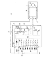
図1は、本発明の第1実施形態に係るオーバヘッドモジュール2を備えたサンルーフシステムAの概略構成の一例を示す図である。図2は、本発明の第1実施形態に係るオーバヘッドモジュール2の外観のイメージ図である。
サンルーフシステムAは、サンルーフ駆動装置1及びオーバヘッドモジュール2を備える。
サンルーフ駆動装置1は、オーバヘッドモジュール2に通信可能に接続されている。
サンルーフ駆動装置1は、サンルーフコントローラ10及びサンルーフモータ11を備える。サンルーフコントローラ10は、オーバヘッドモジュール2と有線又は無線で通信する。サンルーフコントローラ10は、オーバヘッドモジュール2からのモータ駆動信号に基づいて、サンルーフモータ11の回転駆動を制御する。
このサンルーフモータ11は、サンルーフを開閉駆動するモータである。
FIG. 1 is a diagram showing an example of a schematic configuration of a sunroof system A provided with an
The sunroof system A includes a sunroof drive device 1 and an
The sunroof drive device 1 is communicably connected to the
The sunroof drive device 1 includes a
The sunroof motor 11 is a motor that opens and closes the sunroof.
オーバヘッドモジュール2は、例えば、運転席と助手席の間の天井面に設けられている。オーバヘッドモジュール2は、ハウジング(不図示)、基板21、灯体22、灯体用スイッチ23、灯体用回路24、サンルーフ用スイッチ25、マイコン(Central Processing Unit)26及び報知部27を備える。これらの灯体22、灯体用スイッチ23、灯体用回路24、サンルーフ用スイッチ25、マイコン26及び報知部27は一つの基板21上に設けられている。
ハウジングは、車室内のルーフ部に設けられ、車室内側に臨む外壁に開口を有する。基板21は、このハウジング内に設けられている。
The
The housing is provided on the roof portion of the vehicle interior and has an opening on the outer wall facing the vehicle interior side. The
灯体22は、車両用のルームランプである。灯体22は、AS側ランプ221及びDR側ランプ222を備える。例えば、灯体22は、LED(light emitting diode)である。
AS側ランプ221は、アノードが抵抗R1を介してバッテリBTに接続され、カソードが灯体用回路24に接続されている。
DR側ランプ222は、アノードが抵抗R2を介してバッテリBTに接続され、カソードが灯体用回路24に接続されている。
The
In the
In the
灯体用スイッチ23は、ユーザ(車両の乗員)が灯体22を点灯又は消灯(以下、「点消灯」という。)をさせる場合に操作されるスイッチである。灯体用スイッチ23は、マイコン26に接続されている。
灯体用スイッチ23は、AS側ランプスイッチSW1及びDR側ランプスイッチSW2を備える。
AS側ランプスイッチSW1は、ユーザがAS側ランプ221を点消灯させる場合に操作されるスイッチである。AS側ランプスイッチSW1は、ユーザによりAS側ランプ221が操作されると、その操作されたことを示すスイッチ信号がマイコン26に入力される。
The
The
The AS side lamp switch SW1 is a switch that is operated when the user turns on and off the
DR側ランプスイッチSW2は、ユーザがDR側ランプ222を点消灯させる場合に操作されるスイッチである。DR側ランプスイッチSW2は、ユーザによりDR側ランプ222が操作されると、その操作されたことを示すスイッチ信号がマイコン26に入力される。
The DR side lamp switch SW2 is a switch operated when the user turns on and off the
灯体用回路24は、灯体22の点消灯を駆動する駆動回路である。灯体用回路24は、スイッチング素子241及びスイッチング素子242を備える。
スイッチング素子241,242は、FET(FieldEffectiveTransistor;電界効果トランジスタ)、又はIGBT(InsulatedGateBipolarTransistor;絶縁ゲートバイポーラトランジスタ)等である。
The
The switching elements 241,242 are FETs (FieldEffective Transistors; field effect transistors), IGBTs (InsulatedGate Bipolar Transistors; Insulated Gate Bipolar Transistors), and the like.
スイッチング素子241は、マイコン26からの制御信号に基づいて、AS側ランプ221のカソードとGNDとの間を導通状態又は非導通状態に制御する。スイッチング素子242は、マイコン26からの制御信号に基づいて、DR側ランプ222のカソードとGNDとの間を導通状態又は非導通状態に制御する。この制御信号とは、PWM(Pulse Width Modulation)信号である。すなわち、スイッチング素子241及びスイッチング素子242は、マイコン26によるPWM制御により導通状態又は非導通状態が制御される。これにより、灯体22の光量を状況やニーズに合わせて細やかに変化させ、車室内の快適性や居心地を向上させることができる。
The switching
サンルーフ用スイッチ25は、ルーフ部に設けられたサンルーフを開閉するスイッチである。サンルーフ用スイッチ25は、マイコン26に接続されている。
例えば、サンルーフ用スイッチ25は、サンルーフ開スイッチSW3、サンルーフ閉スイッチSW4、オート操作スイッチSW5、傾斜スイッチSW6、リア開SW7及びリア閉SW8を備える。
The
For example, the
サンルーフ開スイッチSW3は、サンルーフを全開させる場合に操作されるスイッチである。このサンルーフ開スイッチSW3は、マイコン26に接続されている。
サンルーフ閉スイッチSW4は、サンルーフを全閉させる場合に操作されるスイッチである。このサンルーフ閉スイッチSW4は、マイコン26に接続されている。
The sunroof open switch SW3 is a switch that is operated when the sunroof is fully opened. The sunroof open switch SW3 is connected to the
The sunroof closing switch SW4 is a switch that is operated when the sunroof is fully closed. The sunroof closing switch SW4 is connected to the
オート操作スイッチSW5は、サンルーフを自動で開閉させる場合に操作されるスイッチである。このオート操作スイッチSW5は、マイコン26に接続されている。
傾斜スイッチSW6は、サンルーフの傾斜を変更する場合に操作されるスイッチである。この傾斜スイッチSW6は、マイコン26に接続されている。
The automatic operation switch SW5 is a switch that is operated when the sunroof is automatically opened and closed. The automatic operation switch SW5 is connected to the
The tilt switch SW6 is a switch that is operated when changing the tilt of the sunroof. The tilt switch SW6 is connected to the
リア開SW7は、サンルーフのリア側を開状態にさせる場合に操作されるスイッチである。このリア開SW7は、マイコン26に接続されている。
リア閉SW8は、サンルーフのリア側を閉状態にさせる場合に操作されるスイッチである。このリア閉SW8は、マイコン26に接続されている。
The rear open SW7 is a switch that is operated when the rear side of the sunroof is opened. The rear open SW7 is connected to the
The rear closing SW8 is a switch that is operated when the rear side of the sunroof is closed. The rear closed SW8 is connected to the
これらのサンルーフ開スイッチSW3、サンルーフ閉スイッチSW4、オート操作スイッチSW5、傾斜スイッチSW6、リア開SW7及びリア閉SW8は、ユーザにより、オン/オフ(スイッチ接点のON/OFF)の操作がされることで、マイコン26に各スイッチ信号が入力する。
These sunroof open switch SW3, sunroof close switch SW4, auto operation switch SW5, tilt switch SW6, rear open SW7 and rear close SW8 are turned on / off (switch contact ON / OFF) by the user. Then, each switch signal is input to the
マイコン26は、灯体用スイッチ23からスイッチ信号を入力されると、そのスイッチ信号に基づいて、PWM制御による灯体22の点消灯を制御する。
また、マイコン26は、サンルーフ用スイッチ25からスイッチ信号を入力されると、そのスイッチ信号に基づいて、サンルーフコントローラ10と通信し、サンルーフモータ11の回転駆動を制御する。
When a switch signal is input from the
Further, when the switch signal is input from the
報知部27は、マイコン26からの報知信号に基づいて、報知する。この報知とは、この報知は、ブザーでもよいし、音声でもよいし、表示でもよいし、それらの組み合わせでもよい。
The
次に、本実施形態に係るサンルーフシステムAに動作について、説明する。
ユーザは、灯体22を点灯させる場合には、灯体用スイッチ23をON状態に操作する。これにより、マイコン26には、灯体用スイッチ23が接続された入力端子にスイッチ信号が入力される。したがって、マイコン26は、スイッチング素子241,242に制御信号を出力することで、灯体22を点灯させる。一方、ユーザは、灯体22を消灯させる場合には、灯体用スイッチ23をOFF状態に操作する。これにより、灯体用スイッチ23が接続された入力端子に入力していたスイッチ信号が消灯する。したがって、マイコン26は、スイッチング素子241,242に対する制御信号の出力を停止するため、灯体22を消灯させる。
Next, the operation of the sunroof system A according to the present embodiment will be described.
When the
また、ユーザは、サンルーフを開状態にする場合には、サンルーフ開スイッチSW3をONに操作する。これにより、マイコン26には、サンルーフ開スイッチSW3が接続された入力端子にスイッチ信号が入力される。したがって、マイコン26は、サンルーフコントローラ10と通信し、正転駆動を示すモータ駆動信号をサンルーフコントローラ10に出力することでサンルーフモータ11を正転駆動させる。
一方、ユーザは、サンルーフを閉状態にする場合には、サンルーフ閉スイッチSW4をONに操作する。これにより、マイコン26には、サンルーフ閉スイッチSW4が接続された入力端子にスイッチ信号が入力される。したがって、マイコン26は、サンルーフコントローラ10と通信し、逆転駆動を示すモータ駆動信号をサンルーフコントローラ10に出力することでサンルーフモータ11を逆転駆動させる。
このように、サンルーフシステムAでは、スイッチの出力を多くのpin数のコネクタや多数のハーネスを用いてサンルーフ駆動装置1に接続する必要がなく、配線の省線化及びシステムの薄型化が可能となる。
Further, when the sunroof is to be opened, the user operates the sunroof open switch SW3 to ON. As a result, the switch signal is input to the input terminal to which the sunroof open switch SW3 is connected to the
On the other hand, when the sunroof is closed, the user operates the sunroof closing switch SW4 to ON. As a result, the switch signal is input to the input terminal to which the sunroof closing switch SW4 is connected to the
In this way, in the sunroof system A, it is not necessary to connect the output of the switch to the sunroof drive device 1 by using a large number of pins or a large number of harnesses, and it is possible to save wiring and make the system thinner. Become.
また、マイコン26は、ユーザがサンルーフを開状態にしたまま、イグニッションスイッチIGSWをオフした場合には、報知部27に報知信号を出力する。これにより、マイコン26は、サンルーフが開状態であることをユーザに報知することができる。また、マイコン26は、ユーザがサンルーフを開状態にしたまま、イグニッションスイッチIGSWをオフした場合には、灯体22を点灯させるように制御してもよい。これにより、マイコン26は、サンルーフが開状態であることをユーザに報知することができる。このように、マイコン26は、サンルーフの動作と連動して、報知部27の動作や灯体22の点消灯を制御することができる。なお、マイコン26は、サンルーフコントローラ10からサンルーフモータ11の回転位置を示す信号を取得することで、サンルーフの位置を検出することができる。そのため、マイコン26は、サンルーフコントローラ10から出力された信号に基づいて、サンルーフが開状態か否かを判別することができる。
Further, when the user turns off the ignition switch IGSW while the sunroof is open, the
上述したように、本実施形態に係るオーバヘッドモジュール2は、車室内のルーフ部に設けられ、車室内側に臨む外壁に開口を有するハウジングを備える。また、灯体22と、灯体22を点消灯する灯体用スイッチ23と、灯体22の点消灯を駆動する灯体用回路24と、ルーフ部に設けられたサンルーフを開閉するサンルーフ用スイッチ25と、がそのハウジング内の一つの基板21上に設けられている。また、この基板21には、サンルーフ用スイッチ25と接続されたマイコン26が設けられ、このマイコン26は、サンルーフを駆動させるサンルーフモータ11と通信接続される。これにより、サンルーフ用スイッチ25スイッチの出力を多くのpin数のコネクタや多数のハーネスを用いてサンルーフ駆動装置1に接続する必要がなく、配線の省線化が可能となる。
As described above, the
マイコン26は、さらに、灯体用回路24と灯体用スイッチ23とに接続されている。
そして、マイコン26は、サンルーフモータ11から送信された信号をマイコン26が受信し、受信した信号に応じて灯体22の点消灯を制御する。これにより、マイコン26は、サンルーフの動作と連動して、灯体22の点消灯を制御することができる。
The
Then, the
以上、この発明の第1実施形態について図面を参照して詳述してきたが、具体的な構成はこの第1実施形態に限られるものではなく、この発明の要旨を逸脱しない範囲の設計等も含まれる。
例えば、図3に示すように、本実施形態のオーバヘッドモジュール2は、サンルーフ駆動装置1以外にも、テールゲートを開閉するテールゲート駆動装置100や車体の後方を映し出すカメラ装置200に対しても連動して動作可能である。このカメラ装置200は、テールゲートに設けられたカメラが撮影した映像を車室内のモニタに表示する装置である。例えば、オーバヘッドモジュール2は、テールゲート駆動装置100とカメラ装置200とにそれぞれ通信接続されている。オーバヘッドモジュール2は、テールゲート駆動装置100からの信号により、テールゲートの開動作を検出する。そして、オーバヘッドモジュール2は、そのテールゲートの開動作を検出した場合には、カメラ装置200と通信することで車体の後方のモニタ表示を停止させ、ルームミラーに切り替えるように制御してもよい。このように、オーバヘッドモジュール2は、車両に設けられた複数の外部装置にそれぞれ通信可能に設けれられており、各外部装置の動作を集中監視している。これにより、オーバヘッドモジュール2は、外部装置間の連動を制御することができる。
Although the first embodiment of the present invention has been described in detail with reference to the drawings, the specific configuration is not limited to the first embodiment, and the design and the like within a range not deviating from the gist of the present invention are also included. included.
For example, as shown in FIG. 3, the
また、オーバヘッドモジュール2は、外部装置を駆動する外部装置用スイッチと、この外部装置用スイッチと接続されたマイコンとが一つの基板に実装され、このマイコンは、外部装置に対して通信接続されるように構成されてもよい。
なお、本実施形態の基板21には、スイッチとして、灯体22を点消灯する灯体用スイッチのみが設けられてもよい。そして、この場合には、マイコン26は、ハウジングの外部に設けられた上記外部装置を駆動する外部装置用回路と通信接続することで、その外部装置との間で信号を送受信することができる。
Further, in the
The
上述のオーバヘッドモジュール2Bは、サンルーフ駆動装置1以外にも、他の車両に設けられた外部装置(例えば、テールゲート駆動装置100、カメラ装置200、スライドドアの駆動装置、パワーウインドの駆動装置)にも適用可能である。
The
(第2実施形態)
次に、この発明の第2実施形態を図4に基づいて説明する。なお、第1実施形態と同一態様には、同一符号を付して説明する。
図4は、本発明の第2実施形態に係るオーバヘッドモジュール2Bを備えたサンルーフシステムBの概略構成の一例を示す図である。
この第2実施形態において、オーバヘッドモジュール2Bは、車室内のルーフ部に設けられ、車室内側に臨む外壁に開口を有するハウジングを備え、灯体22と灯体22を点消灯する灯体用スイッチ23と灯体22の点消灯を制御する灯体用回路24とルーフ部に設けられたサンルーフを開閉するサンルーフ用スイッチ25とがハウジング内の一つの基板21上に設けられた点、基板21上には、サンルーフ用スイッチ25と接続されたマイコン26が設けられている点等の基本的構成は前述した第1実施形態と同様である。
(Second Embodiment)
Next, a second embodiment of the present invention will be described with reference to FIG. The same embodiment as that of the first embodiment will be described with the same reference numerals.
FIG. 4 is a diagram showing an example of a schematic configuration of a sunroof system B provided with an
In the second embodiment, the
ここで、図4に示すように、第2実施形態と第1実施形態との相違点は、第2実施形態のサンルーフシステムBはサンルーフコントローラ10を備えておらず、第2実施形態のマイコン26とサンルーフモータ111とは通信接続されていない点にある。
Here, as shown in FIG. 4, the difference between the second embodiment and the first embodiment is that the sunroof system B of the second embodiment does not include the
より詳しくは、サンルーフモータ111は、コイルが巻回された回転軸と、回転軸に設けられ、コイルが接続されるセグメントと、セグメントに摺接するブラシとを備えている。サンルーフモータ111は車両に設けられた電源と電源用回路で接続されており、マイコン26は、サンルーフモータ111と電源用回路によって接続されている。
More specifically, the
ここで、サンルーフモータ111において、セグメントは回転軸の径方向に沿って複数個並設され、各セグメント同士の間には所定の隙間が設けられている。このため、サンルーフモータ111が駆動し、ブラシが回転するセグメントに摺接する際には、ブラシが複数のセグメントを跨いで通電する時と跨がないで通電する時とで抵抗値が変化する。よって、サンルーフモータ111に接続された電源回路の出力側の電流には、ブラシとセグメントの位置関係によってリップル電流が生じる。このリップル電流を電流検出部301で検出し、位相シフト部302によってパルス信号化し、このパルス信号がマイコンに入力される。このパルス信号は、各パルスが、ブラシとセグメントとの接触の切り替わりに対応している。したがって、マイコン26はパルス信号化されたサンルーフモータ111のリップル電流を検出し、そのパルスをカウントすることでサンルーフモータ111の回転速度や回転角度を算出することができる。
Here, in the
これにより、マイコン26とサンルーフモータ111とを通信接続せず、さらにサンルーフコントローラ10やサンルーフモータ111の回転位置検出用素子を備えない構成であっても、第1実施形態と同様に、マイコン26はサンルーフの挟み込み防止や、サンルーフと灯体22との連動した制御が可能になる。
As a result, even if the
なお、上述の実施形態において、一つの基板とは、ハウジング内に設けられた複数ある基板のうちの一つの基板でもよいし、ハウジング内に一つだけ設けられた基板であってもよい。 In the above-described embodiment, the one substrate may be one of a plurality of substrates provided in the housing, or may be only one substrate provided in the housing.
特許請求の範囲、明細書、及び図面中において示した装置、システム、プログラム、及び方法における動作、手順、ステップ、及び段階等の各処理の実行順序は、特段「より前に」、「先立って」等と明示しておらず、また、前の処理の出力を後の処理で用いるのでない限り、任意の順序で実現しうることに留意すべきである。特許請求の範囲、明細書、及び図面中の動作フローに関して、便宜上「まず、」、「次に、」等を用いて説明したとしても、この順で実施することが必須であることを意味するものではない。 The execution order of each process such as operation, procedure, step, and step in the device, system, program, and method shown in the claims, the specification, and the drawings is particularly "before" and "prior to". It should be noted that it can be realized in any order unless the output of the previous process is used in the subsequent process. Even if the scope of claims, the specification, and the operation flow in the drawings are explained using "first", "next", etc. for convenience, it means that it is essential to carry out in this order. It's not a thing.
A サンルーフシステム
1 サンルーフ駆動装置
2 オーバヘッドモジュール
21 基板
22 灯体
23 灯体用スイッチ
24 灯体用回路
25 サンルーフ用スイッチ
26 マイコン
27 報知部
A Sunroof system 1
Claims (6)
灯体と、
メカニカルスイッチであり、前記灯体を点消灯する灯体用スイッチと、
前記灯体の点消灯を制御する灯体用回路と、
メカニカルスイッチであり、前記ルーフ部に設けられたサンルーフを開閉するサンルーフ用スイッチと、
を備え、
前記灯体、前記灯体用スイッチ、前記灯体用回路及び前記サンルーフ用スイッチは、前記ハウジング内の一つの基板上に設けられ、
前記基板上には、前記サンルーフ用スイッチと接続されたマイコンが設けられ、
前記マイコンは、前記サンルーフを駆動させるサンルーフ駆動装置に対して通信接続されたオーバヘッドモジュール。 A housing that is installed on the roof of the passenger compartment and has an opening on the outer wall facing the passenger compartment .
And a light body,
A mechanical switch, a switch for a lamp that turns on and off the lamp, and a switch for the lamp .
A lamp circuit that controls turning on and off of the lamp ,
A mechanical switch, a sunroof switch that opens and closes the sunroof provided on the roof, and a sunroof switch .
With
The lamp body, the lamp body switch, the lamp body circuit, and the sunroof switch are provided on one substrate in the housing .
A microcomputer connected to the sunroof switch is provided on the board.
The microcomputer is an overhead module that is communication-connected to a sunroof drive device that drives the sunroof.
灯体と、
メカニカルスイッチであり、前記灯体を点消灯する灯体用スイッチと、
前記灯体の点消灯を制御する灯体用回路と、
前記ハウジングの外部に設けられた外部装置を駆動する外部装置用スイッチと、
を備え、
前記灯体、前記灯体用スイッチ、前記灯体用回路及び前記外部装置用スイッチは、前記ハウジング内の一つの基板上に設けられ、
前記基板には、前記外部装置用スイッチと接続されたマイコンが設けられ、
前記マイコンは、前記外部装置に対して通信接続されたオーバヘッドモジュール。 A housing that is installed on the roof of the passenger compartment and has an opening on the outer wall facing the passenger compartment .
And a light body,
A mechanical switch, a switch for a lamp that turns on and off the lamp, and a switch for the lamp .
A lamp circuit that controls turning on and off of the lamp ,
A switch for an external device that drives an external device provided outside the housing ,
With
The lamp body, the lamp body switch, the lamp body circuit, and the external device switch are provided on one substrate in the housing .
A microcomputer connected to the switch for the external device is provided on the board.
The microcomputer is an overhead module that is communication-connected to the external device.
灯体と、
メカニカルスイッチであり、車両の乗員が操作可能なスイッチと、
前記灯体の点消灯を制御する灯体用回路と、
を備え、
前記灯体、前記スイッチ及び前記灯体用回路は、前記ハウジング内の一つの基板上に設けられ、
前記スイッチは前記灯体を点消灯する灯体用スイッチのみが設けられ、
前記基板には、前記ハウジングの外部に設けられた外部装置を駆動する外部装置用回路と通信接続されたマイコンが設けられ、
前記マイコンは、前記外部装置との間で信号を送受信するオーバヘッドモジュール。 A housing that is installed on the roof of the passenger compartment and has an opening on the outer wall facing the passenger compartment .
With the lamp
Is a mechanical switch, and the switch crew of the possible operation of vehicles,
And light body for a circuit to control the off point before Symbol lamp body,
With
The lamp body, the switch, and the lamp body circuit are provided on one substrate in the housing .
The switch is provided only with a lamp switch for turning on and off the lamp.
The substrate is provided with a microcomputer that is communication-connected with a circuit for an external device that drives an external device provided outside the housing.
The microcomputer is an overhead module that transmits and receives signals to and from the external device.
Priority Applications (3)
| Application Number | Priority Date | Filing Date | Title |
|---|---|---|---|
| JP2017046707A JP6815906B2 (en) | 2017-03-10 | 2017-03-10 | Overhead module |
| CN201880013328.3A CN110325403B (en) | 2017-03-10 | 2018-02-28 | Overhead module |
| PCT/JP2018/007534 WO2018163933A1 (en) | 2017-03-10 | 2018-02-28 | Overhead module |
Applications Claiming Priority (1)
| Application Number | Priority Date | Filing Date | Title |
|---|---|---|---|
| JP2017046707A JP6815906B2 (en) | 2017-03-10 | 2017-03-10 | Overhead module |
Publications (2)
| Publication Number | Publication Date |
|---|---|
| JP2018149887A JP2018149887A (en) | 2018-09-27 |
| JP6815906B2 true JP6815906B2 (en) | 2021-01-20 |
Family
ID=63448916
Family Applications (1)
| Application Number | Title | Priority Date | Filing Date |
|---|---|---|---|
| JP2017046707A Active JP6815906B2 (en) | 2017-03-10 | 2017-03-10 | Overhead module |
Country Status (3)
| Country | Link |
|---|---|
| JP (1) | JP6815906B2 (en) |
| CN (1) | CN110325403B (en) |
| WO (1) | WO2018163933A1 (en) |
Families Citing this family (1)
| Publication number | Priority date | Publication date | Assignee | Title |
|---|---|---|---|---|
| CN112285556A (en) * | 2020-09-27 | 2021-01-29 | 芜湖莫森泰克汽车科技股份有限公司 | Quick detection method for skylight speed regulating motor |
Family Cites Families (9)
| Publication number | Priority date | Publication date | Assignee | Title |
|---|---|---|---|---|
| JPH0645303B2 (en) * | 1987-05-12 | 1994-06-15 | 株式会社大井製作所 | Sun roof controller |
| FR2847526B1 (en) * | 2002-11-26 | 2005-08-26 | Dav | BI-FUNCTIONAL CEILING LAMP, IN PARTICULAR FOR MOTOR VEHICLE |
| JP4003672B2 (en) * | 2003-03-12 | 2007-11-07 | 株式会社デンソー | Sound switch |
| JP2005075267A (en) * | 2003-09-03 | 2005-03-24 | Auto Network Gijutsu Kenkyusho:Kk | Control system in cabin |
| JP5519487B2 (en) * | 2010-12-28 | 2014-06-11 | 小島プレス工業株式会社 | Switch device and vehicle interior lighting device |
| JP6499870B2 (en) * | 2015-01-23 | 2019-04-10 | 矢崎総業株式会社 | Car interior lighting system |
| CN105939153B (en) * | 2015-03-02 | 2022-04-22 | 福特全球技术公司 | Proximity switch with false touch adaptive learning and method |
| CN204641539U (en) * | 2015-03-30 | 2015-09-16 | 北京汽车研究总院有限公司 | A kind of ceiling light control panel and automobile |
| CN106274744A (en) * | 2016-08-29 | 2017-01-04 | 芜湖安瑞光电有限公司 | Roof light skylight controls assembly and control method thereof |
-
2017
- 2017-03-10 JP JP2017046707A patent/JP6815906B2/en active Active
-
2018
- 2018-02-28 CN CN201880013328.3A patent/CN110325403B/en active Active
- 2018-02-28 WO PCT/JP2018/007534 patent/WO2018163933A1/en active Application Filing
Also Published As
| Publication number | Publication date |
|---|---|
| JP2018149887A (en) | 2018-09-27 |
| CN110325403A (en) | 2019-10-11 |
| WO2018163933A1 (en) | 2018-09-13 |
| CN110325403B (en) | 2023-06-13 |
Similar Documents
| Publication | Publication Date | Title |
|---|---|---|
| US6529123B1 (en) | Automatically deployable and stowable display monitor | |
| US8994524B2 (en) | Pulsed indication unit for vehicle | |
| US10857934B2 (en) | Vehicle lighting system | |
| JP6815906B2 (en) | Overhead module | |
| CN110300832B (en) | Opening/closing body drive motor and opening/closing body drive system | |
| KR20180044604A (en) | Memory power seat controlling apparatus in vehicle, and controlling method thereof | |
| JP2006327580A (en) | Outer rearview mirror unit for automobile with shape memory driving means | |
| JP2007008409A (en) | Power source controller | |
| JP5128250B2 (en) | Destination setting control circuit | |
| US9190883B2 (en) | Current switching pulse servo | |
| JP4984291B2 (en) | Air conditioner for vehicles | |
| JP4494990B2 (en) | Control device | |
| JP4737075B2 (en) | In-vehicle headlamp light distribution control device and in-vehicle headlamp | |
| US20220266799A1 (en) | In-vehicle power supply system | |
| WO2022249284A1 (en) | Load control device, load control system, and load control method | |
| US20060290308A1 (en) | Switch Assembly for Driving Load and Load Driving Apparatus Including the Same | |
| WO2021020175A1 (en) | In-vehicle power supply system | |
| JP6984542B2 (en) | Open / close member control device | |
| JP3855948B2 (en) | Actuator system | |
| US20160368420A1 (en) | Vehicle mirror device | |
| WO2022194314A1 (en) | Vehicle, additional unit for vehicle and method of switching of the vehicle vent control | |
| KR20170045449A (en) | Circuit for switch use for power window of a car having a prevention of malfunction | |
| JP2005008030A (en) | Motor actuator | |
| KR0150932B1 (en) | Roomlamp aiming device of a car | |
| JP2003212067A (en) | Control device for vehicle |
Legal Events
| Date | Code | Title | Description |
|---|---|---|---|
| RD03 | Notification of appointment of power of attorney |
Free format text: JAPANESE INTERMEDIATE CODE: A7423 Effective date: 20181026 |
|
| A621 | Written request for application examination |
Free format text: JAPANESE INTERMEDIATE CODE: A621 Effective date: 20190916 |
|
| A131 | Notification of reasons for refusal |
Free format text: JAPANESE INTERMEDIATE CODE: A131 Effective date: 20200519 |
|
| A521 | Request for written amendment filed |
Free format text: JAPANESE INTERMEDIATE CODE: A523 Effective date: 20200707 |
|
| TRDD | Decision of grant or rejection written | ||
| A01 | Written decision to grant a patent or to grant a registration (utility model) |
Free format text: JAPANESE INTERMEDIATE CODE: A01 Effective date: 20201215 |
|
| A61 | First payment of annual fees (during grant procedure) |
Free format text: JAPANESE INTERMEDIATE CODE: A61 Effective date: 20201223 |
|
| R150 | Certificate of patent or registration of utility model |
Ref document number: 6815906 Country of ref document: JP Free format text: JAPANESE INTERMEDIATE CODE: R150 |
|
| S111 | Request for change of ownership or part of ownership |
Free format text: JAPANESE INTERMEDIATE CODE: R313113 |
|
| R350 | Written notification of registration of transfer |
Free format text: JAPANESE INTERMEDIATE CODE: R350 |
|
| R250 | Receipt of annual fees |
Free format text: JAPANESE INTERMEDIATE CODE: R250 |