JP6814552B2 - Washing machine - Google Patents

Washing machine Download PDF

Info

Publication number
JP6814552B2
JP6814552B2 JP2016102665A JP2016102665A JP6814552B2 JP 6814552 B2 JP6814552 B2 JP 6814552B2 JP 2016102665 A JP2016102665 A JP 2016102665A JP 2016102665 A JP2016102665 A JP 2016102665A JP 6814552 B2 JP6814552 B2 JP 6814552B2
Authority
JP
Japan
Prior art keywords
lid
spring
washing machine
end portion
reinforcing member
Prior art date
Legal status (The legal status is an assumption and is not a legal conclusion. Google has not performed a legal analysis and makes no representation as to the accuracy of the status listed.)
Active
Application number
JP2016102665A
Other languages
Japanese (ja)
Other versions
JP2017209174A (en
Inventor
和則 神沢
和則 神沢
翔悟 山村
翔悟 山村
良典 臼井
良典 臼井
Current Assignee (The listed assignees may be inaccurate. Google has not performed a legal analysis and makes no representation or warranty as to the accuracy of the list.)
Toshiba Lifestyle Products and Services Corp
Original Assignee
Toshiba Lifestyle Products and Services Corp
Priority date (The priority date is an assumption and is not a legal conclusion. Google has not performed a legal analysis and makes no representation as to the accuracy of the date listed.)
Filing date
Publication date
Application filed by Toshiba Lifestyle Products and Services Corp filed Critical Toshiba Lifestyle Products and Services Corp
Priority to JP2016102665A priority Critical patent/JP6814552B2/en
Publication of JP2017209174A publication Critical patent/JP2017209174A/en
Application granted granted Critical
Publication of JP6814552B2 publication Critical patent/JP6814552B2/en
Active legal-status Critical Current
Anticipated expiration legal-status Critical

Links

Images

Landscapes

  • Main Body Construction Of Washing Machines And Laundry Dryers (AREA)

Description

本発明の実施形態は、洗濯機に関する。 Embodiments of the present invention relate to washing machines.

従来の縦型洗濯機に用いられる洗濯蓋の構造は、ヒンジ部を板金部品によるベースに、シャフトとねじりコイルばねとダンパを用いて回動を制御する構成である。しかし、ねじりコイルバネとして、硬いバネを使用する場合が多く、このためバネを容易に取り付けることが困難であった。 The structure of the washing lid used in the conventional vertical washing machine is such that the hinge portion is used as a base made of sheet metal parts, and the rotation is controlled by using a shaft, a torsion coil spring and a damper. However, a hard spring is often used as the torsion coil spring, which makes it difficult to easily attach the spring.

特開2007−195781号公報JP-A-2007-195781

そこで、バネの動きを規制し、また、バネの取り回しの自由度を高くすることで、蓋のヒンジ部のバネを取り付けやすくした洗濯機を提供することを目的とする。 Therefore, it is an object of the present invention to provide a washing machine in which the movement of the spring is regulated and the degree of freedom of handling the spring is increased so that the spring of the hinge portion of the lid can be easily attached.

実施形態に係る冷蔵庫は、洗濯機本体と、前記洗濯機本体の上部に設けられた洗濯物出入用の開口部と、前記開口部を開閉する蓋と、前記蓋を回動可能に支持する支持部材と、を備え、前記支持部材は、前記蓋の回動軸となるシャフトと、前記蓋の開放側に付勢力を付与するバネと、前記シャフト、及び前記バネが装着される補強部材と、を備えており、前記バネは、内側に前記シャフトが挿入されたコイル部と、直線状の第1の端部及び第2の端部と、を備え、前記補強部材は、少なくとも、前記第1の端部が前記補強部材に装着された状態で前記第1の端部に当接して前記第1の端部の後方向の動きを規制する後規制部と、前記後規制部と前記コイル部との間に位置し前記第1の端部が前記補強部材に装着された状態で前記第1の端部に当接して前記第1の端部の前方向の動きを規制する前規制部と、を備え、前記後規制部は、前記補強部材に設けられた穴部に形成されている。 The refrigerator according to the embodiment includes a washing machine main body, an opening for entering and exiting laundry provided in the upper part of the washing machine main body, a lid for opening and closing the opening, and a support for rotatably supporting the lid. The support member includes a shaft that serves as a rotation axis of the lid, a spring that applies an urging force to the open side of the lid, the shaft, and a reinforcing member to which the spring is mounted. The spring includes a coil portion into which the shaft is inserted , a linear first end portion and a second end portion, and the reinforcing member is at least the first. a restricting unit after the end regulates the movement after the said first end portion in a state of being attached to the reinforcing member in contact with said first end of said and the rear restricting portion coil portion With the pre-regulatory portion located between the first end portion and abutting the first end portion in a state where the first end portion is attached to the reinforcing member to regulate the forward movement of the first end portion. , And the post-regulatory portion is formed in a hole provided in the reinforcing member.

本実施形態に係る洗濯機の構成例を示すものであり、蓋が閉じられた閉状態を示す洗濯機の斜視図A configuration example of the washing machine according to the present embodiment is shown, and a perspective view of the washing machine showing a closed state in which the lid is closed. 本実施形態に係る洗濯機の構成例を示すものであり、蓋が開いた開状態を示す洗濯機の斜視図A configuration example of the washing machine according to the present embodiment is shown, and a perspective view of the washing machine showing an open state with the lid open. 開状態における洗濯機の側面図Side view of the washing machine in the open state 閉状態における洗濯機の上部を示す縦断側面図Longitudinal side view showing the upper part of the washing machine in the closed state 蓋及び回動軸部の外観構成を示す斜視図A perspective view showing the external configuration of the lid and the rotating shaft portion. 回動軸部内部の概略構成を示す斜視図A perspective view showing a schematic configuration inside the rotating shaft portion. バネ周りの概略構成を示す正面図Front view showing the schematic configuration around the spring バネ周りの概略構成を示す上方からの斜視図A perspective view from above showing a schematic configuration around the spring バネ周りの概略構成を示す下方からの斜視図View from below showing the schematic configuration around the spring 図7のA−A線に沿った部分の概略構成を示す断面図Sectional drawing which shows the schematic structure of the part along the line AA of FIG. (a)は第1規制部の概略構成を拡大して示す上面図、(b)は第2規制部の概略構成を拡大して示す下面図(A) is an enlarged top view showing the schematic configuration of the first regulation unit, and (b) is an enlarged bottom view showing the schematic configuration of the second regulation unit. 実施形態の変形例に係るバネ周りの概略構成を示す上方からの斜視図A perspective view from above showing a schematic configuration around a spring according to a modified example of the embodiment. 図7のA−A線に沿った部分の概略構成を示す断面図Sectional drawing which shows the schematic structure of the part along the line AA of FIG. 第1規制部の概略構成を拡大して示す上面図Top view showing an enlarged schematic configuration of the first regulation section

以下、実施形態による洗濯機を、図面を参照しながら説明する。なお、実施形態において実質的に同一の構成部位には同一の符号を付し、説明を省略する。
図1から図4に例示する洗濯機1は、洗濯槽の回転軸が縦方向であるいわゆる縦軸型の洗濯機である。洗濯機1は、洗濯機本体2、及び、洗濯機本体2の上部に矩形板状の蓋3を備える。蓋3の左右方向の幅は、洗濯機本体2の左右方向の幅とほぼ同じ寸法となっている。なお、以下、「ほぼ同じ寸法」とは、両者が完全に一致する寸法である場合を含み、また、両者の寸法が同一と見做せるほど僅かに異なる場合も含む。
Hereinafter, the washing machine according to the embodiment will be described with reference to the drawings. In the embodiment, substantially the same constituent parts are designated by the same reference numerals, and the description thereof will be omitted.
The washing machine 1 illustrated in FIGS. 1 to 4 is a so-called vertical axis type washing machine in which the rotation axis of the washing tub is in the vertical direction. The washing machine 1 includes a washing machine main body 2 and a rectangular plate-shaped lid 3 on the upper part of the washing machine main body 2. The width of the lid 3 in the left-right direction is substantially the same as the width of the washing machine main body 2 in the left-right direction. In the following, "almost the same size" includes a case where the two dimensions are completely the same, and also includes a case where the two dimensions are slightly different so as to be regarded as the same.

洗濯機本体2は、例えば鋼板により構成される矩形箱状の外箱4と、例えば合成樹脂により構成されるトップカバー5と、を備える。トップカバー5は、外箱4の上部に設けられている。即ち、トップカバー5は、洗濯機本体2の上部を構成する。 The washing machine main body 2 includes, for example, a rectangular box-shaped outer box 4 made of steel plate, and a top cover 5 made of, for example, synthetic resin. The top cover 5 is provided on the upper part of the outer box 4. That is, the top cover 5 constitutes the upper part of the washing machine main body 2.

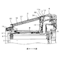
図4に例示するように、外箱4の内部には、洗濯水を溜める水槽6が、図示しない弾性吊持機構により弾性的に支持されている。そして、この水槽6の内部には、洗濯物が収容される洗濯槽7が回転可能に設けられている。洗濯槽7の回転軸は、洗濯機本体2の上下方向に延びる縦軸である。水槽6の上部には、内蓋8を有する水槽カバー9が設けられている。 As illustrated in FIG. 4, a water tank 6 for storing washing water is elastically supported inside the outer box 4 by an elastic suspension mechanism (not shown). A washing tub 7 for accommodating laundry is rotatably provided inside the water tub 6. The rotation axis of the washing tub 7 is a vertical axis extending in the vertical direction of the washing machine main body 2. A water tank cover 9 having an inner lid 8 is provided on the upper part of the water tank 6.

トップカバー5は、下面が開口し、上面が前方に向けて下降傾斜する薄形の中空箱状をなす。トップカバー5の中央部には、洗濯槽7の上方に位置して、洗濯物出入用の開口部10が設けられている。開口部10は、前側が円弧状に開口し、後側が矩形状に開口する。開口部10は、トップカバー5の上面から下面にかけて同じ形状、つまり、前側が円弧状、後側が矩形状となる、上下方向に深さを有した開口となっている。この場合、トップカバー5の上面は前方に向けて下降傾斜しているので、開口部10の深さは、前側よりも後側の方が深い。 The top cover 5 has a thin hollow box shape in which the lower surface is open and the upper surface is inclined downward toward the front. At the center of the top cover 5, an opening 10 for entering and exiting laundry is provided above the washing tub 7. The opening 10 opens in an arc shape on the front side and in a rectangular shape on the rear side. The opening 10 has the same shape from the upper surface to the lower surface of the top cover 5, that is, the opening has an arc shape on the front side and a rectangular shape on the rear side, and has a depth in the vertical direction. In this case, since the upper surface of the top cover 5 is inclined downward toward the front, the depth of the opening 10 is deeper on the rear side than on the front side.

開口部10を開閉する蓋3は、トップカバー5の上面において前後方向に回動可能に設けられている。即ち、蓋3の基端部には、左右方向に延びる回動軸部11が設けられている。回動軸部11は、洗濯機本体2に対し、蓋3を回動可能に支持する支持部材である。回動軸部11は、蓋3の基端部において当該蓋3の左右方向に延びる円筒状をなしている。 The lid 3 that opens and closes the opening 10 is provided on the upper surface of the top cover 5 so as to be rotatable in the front-rear direction. That is, a rotating shaft portion 11 extending in the left-right direction is provided at the base end portion of the lid 3. The rotation shaft portion 11 is a support member that rotatably supports the lid 3 with respect to the washing machine main body 2. The rotating shaft portion 11 has a cylindrical shape extending in the left-right direction of the lid 3 at the base end portion of the lid 3.

一方、トップカバー5の上部において開口部10よりも後側となる部分には、トップカバー5の左右方向に延びる凹部12が設けられている。凹部12は、円筒状の回動軸部11の形状に対応するように断面円弧状に窪んだ形状となっている。凹部12の左右方向の幅は、トップカバー5の左右方向の幅、換言すれば洗濯機本体2の左右方向の幅とほぼ同じ寸法となっている。従って、凹部12は、その左右方向の両端部が塞がれておらず、洗濯機本体2の側方に向けて露出した構成となっている。そして、蓋3の回動軸部11は、洗濯機本体2側の凹部12に収容される。これにより、蓋3は、洗濯機本体2の上部に回動可能に支持される。 On the other hand, a recess 12 extending in the left-right direction of the top cover 5 is provided in a portion of the upper portion of the top cover 5 that is behind the opening 10. The recess 12 has a shape recessed in an arc shape in cross section so as to correspond to the shape of the cylindrical rotating shaft portion 11. The width of the recess 12 in the left-right direction is substantially the same as the width of the top cover 5 in the left-right direction, in other words, the width of the washing machine main body 2 in the left-right direction. Therefore, both ends of the recess 12 in the left-right direction are not closed, and the recess 12 is exposed toward the side of the washing machine main body 2. The rotating shaft portion 11 of the lid 3 is housed in the recess 12 on the washing machine main body 2 side. As a result, the lid 3 is rotatably supported on the upper part of the washing machine main body 2.

トップカバー5の上部、換言すれば洗濯機本体2の上部には、開口部10を閉じた状態の蓋3を支持する蓋支持部13が設けられている。蓋支持部13は、開口部10の周囲において平面状に設けられている。この場合、蓋支持部13は、開口部10の前端部を除いて当該開口部10の周囲を囲むように形成されている。 A lid support portion 13 for supporting the lid 3 with the opening 10 closed is provided on the upper portion of the top cover 5, in other words, the upper portion of the washing machine main body 2. The lid support portion 13 is provided in a flat shape around the opening 10. In this case, the lid support portion 13 is formed so as to surround the periphery of the opening 10 except for the front end portion of the opening 10.

また、トップカバー5の前部の上部、換言すれば洗濯機本体2の前部の上部には、洗濯機1に各種の操作を入力するための操作パネル14が設けられている。操作パネル14は、蓋支持部13の前部において当該蓋支持部13に連続するように設けられている。蓋支持部13の上面と操作パネル14の上面は、面一となっている。これにより、開口部10の周囲は、蓋支持部13の上面と操作パネル14の上面とからなる、段差の無い連続した平面部によって囲まれた状態となっている。操作パネル14の後部の中央部には、開口部10の前側の開口形状に沿って円弧状に窪む窪み部15が設けられている。 Further, an operation panel 14 for inputting various operations to the washing machine 1 is provided on the upper part of the front part of the top cover 5, in other words, the upper part of the front part of the washing machine main body 2. The operation panel 14 is provided at the front portion of the lid support portion 13 so as to be continuous with the lid support portion 13. The upper surface of the lid support portion 13 and the upper surface of the operation panel 14 are flush with each other. As a result, the periphery of the opening 10 is surrounded by a continuous flat surface portion having no step, which is composed of the upper surface of the lid support portion 13 and the upper surface of the operation panel 14. In the central portion of the rear portion of the operation panel 14, a recess portion 15 that is recessed in an arc shape along the opening shape on the front side of the opening portion 10 is provided.

蓋3の本体部は、裏面カバー16とガラス面材17との間にガラス貼付部材18を備える。裏面カバー16は、例えば結晶性の合成樹脂材料により構成され、薄型の矩形箱状をなしている。裏面カバー16は、蓋3の裏面を構成する。蓋3の裏面は、図1に例示するように当該蓋3が開口部10を閉じた閉状態においては下面となり、図2に例示するように当該蓋3が開口部10を開いた開状態においては前面となる面である。 The main body of the lid 3 includes a glass sticking member 18 between the back cover 16 and the glass surface material 17. The back cover 16 is made of, for example, a crystalline synthetic resin material and has a thin rectangular box shape. The back cover 16 constitutes the back surface of the lid 3. The back surface of the lid 3 is the lower surface when the lid 3 is closed with the opening 10 as illustrated in FIG. 1, and the back surface is the lower surface when the lid 3 is open with the opening 10 as illustrated in FIG. Is the front surface.

ガラス貼付部材18は、例えば合成樹脂材料により構成され、裏面カバー16の内部に収容される。ガラス面材17は、例えば硬質ガラス板により構成され、矩形の薄板状をなしている。ガラス面材17は、着色されていてもよいし、透明であってもよい。ガラス面材17は、ガラス貼付部材18の上面に図示しない両面粘着テープを介して貼り付けられる。ガラス面材17は、蓋3の表面を構成する。蓋3の表面は、図1に例示するように当該蓋3が開口部10を閉じた閉状態においては上面となり、図2に例示するように当該蓋3が開口部10を開いた開状態においては後面となる面である。 The glass sticking member 18 is made of, for example, a synthetic resin material, and is housed inside the back cover 16. The glass surface material 17 is made of, for example, a hard glass plate and has a rectangular thin plate shape. The glass surface material 17 may be colored or may be transparent. The glass surface material 17 is attached to the upper surface of the glass attaching member 18 via a double-sided adhesive tape (not shown). The glass surface material 17 constitutes the surface of the lid 3. The surface of the lid 3 is the upper surface when the lid 3 is closed with the opening 10 as illustrated in FIG. 1, and is the upper surface when the lid 3 is open with the opening 10 as illustrated in FIG. Is the back surface.

そして、蓋3の先端部には、当該蓋3の左右方向、換言すれば洗濯機本体2の左右方向に延びる手掛部20が設けられている。手掛部20は、ユーザが蓋3を開閉する際に手指を掛けるためのものである。この場合、手掛部20は、蓋3の左右方向の幅、換言すれば洗濯機本体2の左右方向の幅とほぼ同じ寸法となっている。なお、手掛部20は、蓋3の左右方向の幅、換言すれば洗濯機本体2の左右方向の幅よりも短いものであってもよい。即ち、本実施形態に係る洗濯機は、蓋3の先端部の一部のみに手掛部を設ける構成も許容される。 The tip of the lid 3 is provided with a clue portion 20 extending in the left-right direction of the lid 3, in other words, in the left-right direction of the washing machine main body 2. The clasp portion 20 is for the user to hang his / her fingers when opening / closing the lid 3. In this case, the handle portion 20 has substantially the same dimensions as the width of the lid 3 in the left-right direction, in other words, the width of the washing machine main body 2 in the left-right direction. The handle portion 20 may be shorter than the width of the lid 3 in the left-right direction, in other words, the width of the washing machine main body 2 in the left-right direction. That is, the washing machine according to the present embodiment may have a configuration in which a handle portion is provided only on a part of the tip portion of the lid 3.

また、図4に例示するように、回動軸部11の内部には、蓋3の回動中心となる回動軸11aが設けられている。回動軸11aは、蓋3の表面と裏面の間に収まる範囲内に設けられている。回動軸11aは、蓋3が開口部10を閉じた状態であるのか開いた状態であるのかに関わらず、常に、開口部10の後端部よりも高い位置において、その高さが変動することなく維持される。回動軸部11にはダンパホルダ32が設けられており、ダンパホルダ32下部は、トップカバー5に設けられたホルダ保持部34に挿入されて保持されている。ホルダ保持部34は例えば金属製の補強板により構成されている。 Further, as illustrated in FIG. 4, a rotation shaft 11a serving as a rotation center of the lid 3 is provided inside the rotation shaft portion 11. The rotating shaft 11a is provided within a range that fits between the front surface and the back surface of the lid 3. The height of the rotation shaft 11a always fluctuates at a position higher than the rear end of the opening 10, regardless of whether the lid 3 is in the closed state or the open state. It is maintained without. A damper holder 32 is provided on the rotating shaft portion 11, and the lower portion of the damper holder 32 is inserted and held in the holder holding portion 34 provided on the top cover 5. The holder holding portion 34 is composed of, for example, a metal reinforcing plate.

一方、図2に例示するように、操作パネル14は、内部の基板23上にリードスイッチ24を備えている。リードスイッチ24は、蓋3が開口部10を閉じた閉状態において、磁石22を有する操作パネル対応部21により覆われる部分の下方に位置している。リードスイッチ24は、磁石22が所定距離以内に接近するとオンし、磁石22が所定距離以上離れるとオフする。洗濯機1の動作全般を制御する図示しない制御装置は、このリードスイッチ24のオン/オフに基づいて、蓋3の開閉を検知する。 On the other hand, as illustrated in FIG. 2, the operation panel 14 includes a reed switch 24 on an internal substrate 23. The reed switch 24 is located below the portion covered by the operation panel corresponding portion 21 having the magnet 22 in the closed state where the lid 3 closes the opening 10. The reed switch 24 is turned on when the magnet 22 approaches within a predetermined distance, and turns off when the magnet 22 is separated by a predetermined distance or more. A control device (not shown) that controls the overall operation of the washing machine 1 detects the opening / closing of the lid 3 based on the on / off of the reed switch 24.

また、図2および図5に示すように、蓋3の裏面には、裏面カバー16が設けられており、裏面カバー16には複数の弾性部材26が取り付けられている。これらの弾性部材26は、蓋3が閉じられる際に、洗濯機本体2の上面に接触する。これにより、弾性部材26は、蓋3が閉じられる際に発生する衝撃を吸収する。この場合、弾性部材26は、蓋3の裏面のうち蓋支持部13の上面に接触する部位のみに設けられており、蓋3の裏面のうち操作パネル14の上面に接触する部分には設けられていない。なお、弾性部材26は、蓋3の裏面のうち操作パネル14の上面に接触する部分にも設けてもよい。 Further, as shown in FIGS. 2 and 5, a back surface cover 16 is provided on the back surface of the lid 3, and a plurality of elastic members 26 are attached to the back surface cover 16. These elastic members 26 come into contact with the upper surface of the washing machine main body 2 when the lid 3 is closed. As a result, the elastic member 26 absorbs the impact generated when the lid 3 is closed. In this case, the elastic member 26 is provided only on the back surface of the lid 3 that contacts the upper surface of the lid support portion 13, and is provided on the back surface of the lid 3 that contacts the upper surface of the operation panel 14. Not. The elastic member 26 may also be provided on the back surface of the lid 3 which is in contact with the upper surface of the operation panel 14.

また、洗濯機1は、水準器27および蓋ロック機構部28を備える。水準器27は、洗濯機1の設置状態を水平に維持するための基準となるものである。蓋ロック機構部28は、蓋3の裏面に設けられた突起孔部29が挿入される挿入孔部30と、この挿入孔部30に挿入された蓋3の突起孔部29に係止する図示しない係止部と、を備える。蓋ロック機構部28は、蓋3が開口部10を閉じることに伴い挿入孔部30に挿入された突起孔部29に、図示しない係止部を係止させる。これにより、蓋ロック機構部28は、蓋3を、開口部10を閉じた状態で回動不能にロックする。 Further, the washing machine 1 includes a spirit level 27 and a lid lock mechanism portion 28. The spirit level 27 serves as a reference for maintaining the installation state of the washing machine 1 horizontally. The lid lock mechanism portion 28 is shown to be locked to an insertion hole portion 30 into which a protrusion hole portion 29 provided on the back surface of the lid 3 is inserted and a protrusion hole portion 29 of the lid 3 inserted into the insertion hole portion 30. It is provided with a locking portion that does not. The lid locking mechanism 28 locks a locking portion (not shown) in the protruding hole 29 inserted into the insertion hole 30 as the lid 3 closes the opening 10. As a result, the lid lock mechanism 28 locks the lid 3 so as not to rotate with the opening 10 closed.

水準器27および蓋ロック機構部28は、洗濯機本体2の上部において開口部10の前部を挟んで左右に分かれて配置されている。この場合、水準器27および蓋ロック機構部28は、何れも、洗濯機本体2の上部のうち蓋支持部13の前部に設けられている。 The spirit level 27 and the lid lock mechanism portion 28 are arranged separately on the left and right sides of the upper portion of the washing machine main body 2 with the front portion of the opening 10 interposed therebetween. In this case, the spirit level 27 and the lid lock mechanism portion 28 are both provided in the front portion of the lid support portion 13 in the upper portion of the washing machine main body 2.

図5は、蓋3及び、これとトップカバー5とを接続する回動軸部11の外観構成を示す斜視図である。図6は、回動軸部11内部の概略構成を示す斜視図である。図7、図8、図9は、それぞれバネ36周りの概略構成を示す正面図、上方からの斜視図、下方からの斜視図である。図10は、図7のA−A線に沿った部分の概略構成を示す断面図である。図11(a)は、第1規制部43の概略構成を拡大して示す上面図であり、図11(b)は、第2規制部44の概略構成を拡大して示す下面図である。 FIG. 5 is a perspective view showing the external configuration of the lid 3 and the rotating shaft portion 11 connecting the lid 3 and the top cover 5. FIG. 6 is a perspective view showing a schematic configuration inside the rotating shaft portion 11. 7, 8 and 9, respectively, are a front view showing a schematic configuration around the spring 36, a perspective view from above, and a perspective view from below. FIG. 10 is a cross-sectional view showing a schematic configuration of a portion along the line AA of FIG. FIG. 11A is an enlarged top view showing the schematic configuration of the first regulation unit 43, and FIG. 11B is an enlarged bottom view showing the schematic configuration of the second regulation unit 44.

図5に示すように、開口部10を開閉する蓋3の基端部には、左右方向に延びる回動軸部11が設けられており、ヒンジカバー31によって覆われている。回動軸部11は、洗濯機本体2のトップカバー5に設けられたホルダ保持部34(図4参照)に、ダンパホルダ32の下部32aを挿入して嵌合することにより保持され、これにより蓋3が洗濯機本体2に固定されている。ホルダ保持部34は、例えば金属製の補強板により構成されており、図4にも示されるように、洗濯機本体2のトップカバー5に設けられた補強板の受け穴部となっている。 As shown in FIG. 5, a rotating shaft portion 11 extending in the left-right direction is provided at the base end portion of the lid 3 that opens and closes the opening 10, and is covered with the hinge cover 31. The rotating shaft portion 11 is held by inserting and fitting the lower portion 32a of the damper holder 32 into the holder holding portion 34 (see FIG. 4) provided on the top cover 5 of the washing machine main body 2, whereby the lid is held. 3 is fixed to the washing machine main body 2. The holder holding portion 34 is composed of, for example, a metal reinforcing plate, and as shown in FIG. 4, is a receiving hole portion of the reinforcing plate provided in the top cover 5 of the washing machine main body 2.

ヒンジカバー31にはスリット31aが設けられており、回動軸部11内部に設けられたバネ36の第1バネ端部36aがスリット31aから突出している。バネ36は、蓋3の開放側に付勢力を付与している。バネ36及び第1バネ端部36aについては後述する。また、回動軸部11には、内部に設けられたシャフト38が露出する間隙部31bが設けられている。間隙部31bにおいて、トップカバー5に設けられた図示しないシャフト保持部によりシャフト38が保持されることにより、蓋3が回動可能に保持されている。 The hinge cover 31 is provided with a slit 31a, and the first spring end portion 36a of the spring 36 provided inside the rotating shaft portion 11 projects from the slit 31a. The spring 36 applies an urging force to the open side of the lid 3. The spring 36 and the first spring end 36a will be described later. Further, the rotating shaft portion 11 is provided with a gap portion 31b in which the shaft 38 provided inside is exposed. In the gap portion 31b, the lid 3 is rotatably held by holding the shaft 38 by a shaft holding portion (not shown) provided on the top cover 5.

図6に示すように、回動軸部11は、補強部材42を備えており、この補強部材42にダンパホルダ32、内部の図示しないダンパを保持するダンパカバー40、バネ36、シャフト38が備えられている。図10に示すように、補強部材42は断面の一部が略S字形状を有し、左右方向を長手方向とした金属製板材の部材であり、前面部42a、底面部42b及び背面部42gを有している。上記の略S字形状を備える個所は、後述する上部折り返し部42eが設けられる箇所である。補強部材42はネジ穴40bを備えており、図示しないネジにより蓋3に取り付けられている。補強部材42は、背面部42gの左右に、前方に突出し、通し穴38cを備えた一対のシャフト固定部38a、38bを備えており、このシャフト固定部38a、38bの通し穴38cにシャフト38が貫通して装着されている。 As shown in FIG. 6, the rotating shaft portion 11 is provided with a reinforcing member 42, and the reinforcing member 42 is provided with a damper holder 32, a damper cover 40 for holding a damper (not shown) inside, a spring 36, and a shaft 38. ing. As shown in FIG. 10, the reinforcing member 42 is a member of a metal plate material having a substantially S-shaped cross section and a longitudinal direction in the left-right direction, and has a front surface portion 42a, a bottom surface portion 42b, and a back surface portion 42g. have. The portion having the above-mentioned substantially S-shape is a portion where the upper folded portion 42e described later is provided. The reinforcing member 42 includes a screw hole 40b, and is attached to the lid 3 by a screw (not shown). The reinforcing member 42 is provided with a pair of shaft fixing portions 38a and 38b projecting forward to the left and right of the back surface portion 42g and having through holes 38c, and the shaft 38 is provided in the through holes 38c of the shaft fixing portions 38a and 38b. It is installed through.

また、補強部材42は、バネ36の第1バネ端部36aを係止するための第1規制部43を、前面部42aの上部において略直角に後方に折り曲げて形成された折り返し部である上部折り返し部42e、及び、前面部42a下部から後方略直角に折り曲げて形成された下部折り返し部42fに備えている。また、補強部材42は、バネ36の第2バネ端部36bを係止するための第2規制部44を、底面部42bに備えている。 Further, the reinforcing member 42 is an upper portion which is a folded portion formed by bending the first restricting portion 43 for locking the first spring end portion 36a of the spring 36 rearward at a substantially right angle on the upper portion of the front surface portion 42a. It is provided in the folded-back portion 42e and the lower folded-back portion 42f formed by bending from the lower portion of the front surface portion 42a at a substantially right angle to the rear. Further, the reinforcing member 42 is provided with a second regulating portion 44 for locking the second spring end portion 36b of the spring 36 on the bottom surface portion 42b.

バネ36は、ねじりコイルバネであり、金属線が巻回してなるコイル部36cと、その両端に、直線形状の第1バネ端部36a、及び第2バネ端部36bを備えて構成されている。第1バネ端部36aと第2バネ端部36bは、バネにねじり力を付加していない状態で、略180度の角度を有している。コイル部36cはコイル軸を中心にして直巻した金属線により構成されており、コイル軸に沿って空洞が形成されている。図7にも示されるように、バネ36は、コイル部36cのコイル軸の空洞にシャフト38を貫通させ、第1バネ端部36aを第1規制部43に係止し、第2バネ端部36bを第2規制部44に係止して保持されている。 The spring 36 is a torsion coil spring, and includes a coil portion 36c formed by winding a metal wire, a linear first spring end portion 36a, and a second spring end portion 36b at both ends thereof. The first spring end portion 36a and the second spring end portion 36b have an angle of approximately 180 degrees in a state where no torsional force is applied to the spring. The coil portion 36c is formed of a metal wire wound series around the coil shaft, and a cavity is formed along the coil shaft. As shown in FIG. 7, the spring 36 penetrates the shaft 38 into the cavity of the coil shaft of the coil portion 36c, locks the first spring end portion 36a to the first regulation portion 43, and has the second spring end portion. 36b is locked and held by the second regulating unit 44.

ダンパホルダ32は、ダンパカバー40内に保持される図示しないダンパの半分程度を内接して保持している。ダンパホルダ32は、ダンパを蓋3に固定するダンパカバー40によって一体的に蓋3に取り付けられている。ダンパカバー40はネジ40aにより補強部材42に螺設されている。ダンパホルダ32、及び、ダンパホルダ32内部に保持されるダンパはダンパ機構を構成する。ダンパホルダ32は、内部に保持するダンパを回転軸として、ダンパによる抵抗力を付与された状態で回動可能に構成されている。すなわち、ダンパ機構は、蓋3の開閉動作に抵抗力を付与することにより蓋3の動きを緩慢化させ、蓋3がゆっくり動作するようにしている。 The damper holder 32 internally holds about half of a damper (not shown) held in the damper cover 40. The damper holder 32 is integrally attached to the lid 3 by a damper cover 40 that fixes the damper to the lid 3. The damper cover 40 is screwed to the reinforcing member 42 by a screw 40a. The damper holder 32 and the damper held inside the damper holder 32 constitute a damper mechanism. The damper holder 32 is configured to be rotatable around a damper held inside as a rotation axis in a state where resistance is applied by the damper. That is, the damper mechanism slows down the movement of the lid 3 by applying a resistance force to the opening / closing operation of the lid 3, so that the lid 3 operates slowly.

バネ36の第1バネ端部36aは、図7から図9に示すように、第1規制部43に係止されている。図10及び図11(a)にも示されるように、第1規制部43は、後規制部43a、左規制部43b、右規制部43c、及び前規制部43dを備えている。なお、図11(a)は、第1規制部43を、図7から図10に示すD方向から視認した上面図である。前面部42aの上端には後方に略直角をなすように折り曲げた上部折り返し部42eが形成されており、上部折り返し部42eにコ字状に切欠き部42cを設け、このコ字状の切欠き部42cの内側の三方が後規制部43a、左規制部43b、及び右規制部43cとなるように構成されている。後規制部43a、左規制部43b、及び右規制部43cは、補強部材42の上端に位置して設けられており、上部折り返し部42eの同一平面上に位置している。コ字状の切欠き部42cの左規制部43bの前部は外方に開放されており、これを通して第1バネ端部36aの出し入れが可能となっている。 The first spring end portion 36a of the spring 36 is locked to the first regulating portion 43 as shown in FIGS. 7 to 9. As shown in FIGS. 10 and 11A, the first regulation unit 43 includes a rear regulation unit 43a, a left regulation unit 43b, a right regulation unit 43c, and a front regulation unit 43d. Note that FIG. 11A is a top view of the first regulation unit 43 viewed from the D direction shown in FIGS. 7 to 10. An upper folded portion 42e that is bent rearward so as to form a substantially right angle is formed at the upper end of the front surface portion 42a, and a U-shaped notch 42c is provided in the upper folded portion 42e, and this U-shaped notch is provided. The three inner sides of the portion 42c are configured to be the rear regulating portion 43a, the left regulating portion 43b, and the right regulating portion 43c. The rear regulating portion 43a, the left regulating portion 43b, and the right regulating portion 43c are provided at the upper ends of the reinforcing member 42, and are located on the same plane of the upper folded portion 42e. The front portion of the left regulating portion 43b of the U-shaped notch portion 42c is open to the outside, through which the first spring end portion 36a can be taken in and out.

後規制部43aは、後ろ方向に付勢される第1バネ端部36aを後方向から前方向に向かって当接し、第1バネ端部36aの後ろ方向への動きを規制している。左規制部43bは突起形状となって前方に張り出しており、その右側に側面を形成し、この側面形状により引っ掛かり部を構成している。左規制部43bはこの側面によって第1バネ端部36aに当接して左方向への動きを規制している。右規制部43cは後規制部43aの右側に位置する側面を構成し、第1バネ端部36aに当接して右方向への動きを規制している。なお、実施形態においては、右規制部43cを上部折り返し部42eの切欠き部42cに設けた例を示したが、これに限る必要はない。例えば、右規制部43cを下部折り返し部42fの穴部42dに、すなわち、前規制部43dに隣接する位置に設けることとしても良い。 The rear regulating portion 43a abuts the first spring end portion 36a urged in the rear direction from the rear direction to the front direction, and regulates the movement of the first spring end portion 36a in the rear direction. The left regulating portion 43b has a protruding shape and projects forward, and a side surface is formed on the right side thereof, and the hooking portion is formed by this side surface shape. The left regulating portion 43b abuts on the first spring end portion 36a by this side surface to regulate the movement to the left. The right regulating portion 43c constitutes a side surface located on the right side of the rear regulating portion 43a, and abuts on the first spring end portion 36a to regulate the movement to the right. In the embodiment, an example in which the right regulating portion 43c is provided in the cutout portion 42c of the upper folded portion 42e is shown, but the present invention is not limited to this. For example, the right regulating portion 43c may be provided in the hole portion 42d of the lower folded portion 42f, that is, at a position adjacent to the front regulating portion 43d.

後規制部43aの下方に位置する補強部材42に設けられた下部折り返し部42fには、穴部42dが形成されている。穴部42dの前方向の端部は前規制部43dを構成している。前規制部43dは第1バネ端部36aに前方から当接し、図10の矢印Eで示される第1バネ端部36aの前方向への動きを規制している。上述した後規制部43aと、この前規制部43dにより、第1バネ端部36aの前後方向の位置決めがなされる。組み立て時において、第1バネ端部36aは、穴部42d及び切欠き部42cを通されて第1規制部43に係止される。 A hole 42d is formed in the lower folded portion 42f provided on the reinforcing member 42 located below the rear regulating portion 43a. The front end of the hole 42d constitutes the front regulating 43d. The front regulating portion 43d abuts on the first spring end portion 36a from the front and restricts the forward movement of the first spring end portion 36a indicated by the arrow E in FIG. The rear regulating portion 43a and the front regulating portion 43d described above position the first spring end portion 36a in the front-rear direction. At the time of assembly, the first spring end portion 36a is locked to the first regulating portion 43 through the hole portion 42d and the notch portion 42c.

穴部42d及び切欠き部42cは大きく形成されている。穴部42d及び切欠き部42cが大きいほどバネ36の自由度が増し、取り回しが容易になるため、洗濯機1の組み立て時において、バネ36の取り付けが容易になる。 The hole portion 42d and the notch portion 42c are formed large. The larger the hole 42d and the notch 42c, the greater the degree of freedom of the spring 36, and the easier it is to handle. Therefore, the spring 36 can be easily attached when the washing machine 1 is assembled.

また、前規制部43dは、図10の矢印Eで示される第1バネ端部36aの前方向の動きを規制する。これにより、バネ36の付勢力によって、バネ36を前方向に押し出す付勢力が抑制される。従って、バネ36のコイル部36cの空洞部の内側が、シャフト38に接触することを抑制する。バネ36のシャフト38への接触を抑制することで、摩擦がなくなるため、蓋3の開閉時の開閉トルクを軽減することができ、これにより蓋3の開閉を円滑に行うことができる。 Further, the front regulating portion 43d regulates the forward movement of the first spring end portion 36a indicated by the arrow E in FIG. As a result, the urging force of the spring 36 suppresses the urging force of pushing the spring 36 forward. Therefore, it is possible to prevent the inside of the hollow portion of the coil portion 36c of the spring 36 from coming into contact with the shaft 38. By suppressing the contact of the spring 36 with the shaft 38, friction is eliminated, so that the opening / closing torque at the time of opening / closing the lid 3 can be reduced, whereby the lid 3 can be smoothly opened / closed.

また、第1バネ端部36aが後規制部43aに当接する位置は、前規制部43dに当接する位置と異なる。すなわち、図10に示されるように、バネ36のコイル部36cから第1バネ端部36aが後規制部43aに当接する位置までの長さL1は、バネ36のコイル部36cから前規制部43dに当接する位置までの長さL2よりも大きい、すなわち後規制部43aは前規制部43dよりもコイル部36cから離れた位置となっている。このように、第1バネ端部36aの後ろ方向への動きを規制する後規制部43aと、バネ36の付勢力を発生するバネ36のコイル部36cとの間に、第1バネ端部36aの前方向への動きを規制する前規制部43dが位置することで、てこの原理により、バネ36がその付勢力によりバネ36を前方向に押し出す動きを、有効に抑制することができる。これにより、バネ36のコイル軸の空洞部の内側が、シャフト38に接触することを抑制することができるため、接触による摩擦の発生が回避されることにより、蓋3の開閉時の開閉トルクが軽減されるため、蓋3の開閉を円滑に行うことができる。 Further, the position where the first spring end portion 36a abuts on the rear regulating portion 43a is different from the position where it abuts on the front regulating portion 43d. That is, as shown in FIG. 10, the length L1 from the coil portion 36c of the spring 36 to the position where the first spring end portion 36a abuts on the rear regulating portion 43a is from the coil portion 36c of the spring 36 to the front regulating portion 43d. The length to the position where it comes into contact with the coil is larger than L2, that is, the rear regulating portion 43a is located farther from the coil portion 36c than the front regulating portion 43d. In this way, the first spring end portion 36a is between the rear regulating portion 43a that regulates the backward movement of the first spring end portion 36a and the coil portion 36c of the spring 36 that generates the urging force of the spring 36. By locating the front regulating portion 43d that regulates the forward movement of the spring 36, the movement of the spring 36 pushing the spring 36 forward by its urging force can be effectively suppressed by the principle of the lever. As a result, it is possible to prevent the inside of the hollow portion of the coil shaft of the spring 36 from coming into contact with the shaft 38, so that the generation of friction due to the contact is avoided, and the opening / closing torque at the time of opening / closing the lid 3 is increased. Since it is reduced, the lid 3 can be opened and closed smoothly.

第2バネ端部36bは第2規制部44に係止されている。第2バネ端部36bが係止される第2規制部44は前方向に開放されたスリットになっている。洗濯機1の組み立て時において、第2バネ端部36bはスリットを通して脱着され、バネ36の取り付けが容易になる。 The second spring end portion 36b is locked to the second regulating portion 44. The second regulating portion 44 to which the second spring end portion 36b is locked is a slit opened in the forward direction. At the time of assembling the washing machine 1, the second spring end portion 36b is attached and detached through the slit, and the spring 36 can be easily attached.

第2規制部44は、図11(b)に示すように、底面部42bに設けられたスリット部44dであり、スリット部44dに、後規制部44a、左規制部44b、及び右規制部44cを備えている。なお、図11(b)は、第2規制部44を、図7から図10に示すF方向から視認した下面図である。 As shown in FIG. 11B, the second regulation portion 44 is a slit portion 44d provided on the bottom surface portion 42b, and the slit portion 44d has a rear regulation portion 44a, a left regulation portion 44b, and a right regulation portion 44c. It has. Note that FIG. 11B is a bottom view of the second regulation unit 44 viewed from the F direction shown in FIGS. 7 to 10.

後規制部44aは第2バネ端部36bの後ろ方向への動きを規制するものであり、左規制部44bは左方向の動きを、右規制部44cは右方向の動きを規制する。バネ36の装着時において、第2バネ端部36bは後ろ方向に付勢されて後規制部44aに密着しており、後規制部44a、左規制部44b、右規制部44cにより位置決めされている。 The rear regulating portion 44a regulates the backward movement of the second spring end portion 36b, the left regulating portion 44b regulates the leftward movement, and the right regulating portion 44c regulates the rightward movement. When the spring 36 is attached, the second spring end portion 36b is urged backward and is in close contact with the rear regulating portion 44a, and is positioned by the rear regulating portion 44a, the left regulating portion 44b, and the right regulating portion 44c. ..

スリット部44dは前方向に開放されており、第2バネ端部36bがトップカバー5に設けられた図示しない係止穴に係止された状態で蓋3が閉じられた際には、第2バネ端部36bはスリット部44dの前方向に回動する。 The slit portion 44d is opened in the forward direction, and when the lid 3 is closed with the second spring end portion 36b locked in a locking hole (not shown) provided in the top cover 5, the second spring portion 44d is opened. The spring end portion 36b rotates in the forward direction of the slit portion 44d.

図12から図14は実施形態に係る洗濯機1の変形例を示す図である。図12は図8相当図であり、図13は図10相当図であり、図14は図11(a)相当図である。変形例において異なる点は、図8において切欠き部42cとしていた箇所を、図12から図14に示すように、上部折り返し部42eに設けられた穴である穴部46とした点である。第1バネ端部36aは穴部46に通されることにより穴部46に係止される。第1バネ端部36aの装着時には、第1バネ端部36aはバネ36の後ろ方向への付勢力により、穴部46の後壁に付勢されている。その他の構成は図1から図11に記載した実施形態と同じである。 12 to 14 are views showing a modified example of the washing machine 1 according to the embodiment. 12 is a diagram corresponding to FIG. 8, FIG. 13 is a diagram corresponding to FIG. 10, and FIG. 14 is a diagram corresponding to FIG. 11 (a). The difference in the modified example is that the notched portion 42c in FIG. 8 is changed to the hole portion 46, which is a hole provided in the upper folded portion 42e, as shown in FIGS. 12 to 14. The first spring end portion 36a is locked to the hole portion 46 by being passed through the hole portion 46. When the first spring end portion 36a is attached, the first spring end portion 36a is urged to the rear wall of the hole portion 46 by the urging force in the rear direction of the spring 36. Other configurations are the same as those of the embodiments described in FIGS. 1 to 11.

この構成により、第1バネ端部36aの前後左右方向への動きが全方位的に規制されるため、蓋3の開閉時に第1バネ端部36aの穴部46からの脱落が防止される。これにより、第1バネ端部36aの前後左右方向の位置決めがされるため、シャフト38の取り付け時に、バネ36が前後左右に移動することを抑制でき、シャフト38の取り付け作業が容易となる。 With this configuration, the movement of the first spring end portion 36a in the front-rear and left-right directions is restricted in all directions, so that the first spring end portion 36a is prevented from falling out from the hole portion 46 when the lid 3 is opened and closed. As a result, the first spring end portion 36a is positioned in the front-rear and left-right directions, so that the spring 36 can be suppressed from moving in the front-rear and left-right directions when the shaft 38 is attached, and the attachment work of the shaft 38 becomes easy.

実施形態に係る洗濯機1によれば、以下の効果を奏する。
実施形態に係る洗濯機1において、バネ36の第1バネ端部36aは、後規制部43a及び前規制部43dに当接して係止されている。これにより、第1バネ端部36aは後規制部43aにより後ろ方向の動きを規制され、前規制部43dにより前方向への動きが規制される。従って、バネ36の開方向への付勢力によってバネ36が前方向に押される動きが抑制され、これによってバネ36のコイル部36cのコイル軸の空洞の内側がシャフト38に接触することを抑制する。従って、バネ36のシャフト38への接触が抑制されるため、蓋3の開閉時の開閉トルクを軽減することができ、これにより蓋3の開閉を円滑に行うことができる。
According to the washing machine 1 according to the embodiment, the following effects are obtained.
In the washing machine 1 according to the embodiment, the first spring end portion 36a of the spring 36 is in contact with the rear regulating portion 43a and the front regulating portion 43d and is locked. As a result, the rear regulating portion 43a regulates the backward movement of the first spring end portion 36a, and the front regulating portion 43d regulates the forward movement. Therefore, the urging force of the spring 36 in the opening direction suppresses the movement of the spring 36 being pushed forward, thereby suppressing the inside of the coil shaft cavity of the coil portion 36c of the spring 36 from coming into contact with the shaft 38. .. Therefore, since the contact of the spring 36 with the shaft 38 is suppressed, the opening / closing torque at the time of opening / closing the lid 3 can be reduced, whereby the lid 3 can be smoothly opened / closed.

また、実施形態に係る洗濯機1において、左規制部43bにより第1バネ端部36aの左方向への動きが規制される。これにより、第1バネ端部36aが左方向に外れることが防止される。右規制部43cにより第1バネ端部36aの右方向への動きが規制され、これにより、第1バネ端部36aが右方向に外れることが防止される。また、これにより、第1バネ端部36aの左右方向の位置決めがされるため、第1バネ端部36aの左右方向への脱落が防止される。更に、シャフト38の取り付け時に、バネ36が左右に移動することを抑制できるため、シャフト38の取り付け作業が容易となる。 Further, in the washing machine 1 according to the embodiment, the left regulating portion 43b restricts the movement of the first spring end portion 36a in the left direction. As a result, the first spring end portion 36a is prevented from coming off to the left. The right regulating portion 43c regulates the movement of the first spring end portion 36a to the right, thereby preventing the first spring end portion 36a from coming off to the right. Further, as a result, the first spring end portion 36a is positioned in the left-right direction, so that the first spring end portion 36a is prevented from falling off in the left-right direction. Further, since the spring 36 can be suppressed from moving to the left and right when the shaft 38 is attached, the attachment work of the shaft 38 becomes easy.

また、実施形態に係る洗濯機1において、左規制部43bの前部が外方に開放され、大きく形成された切欠き部42cを備えている。また、補強部材42に設けられた下部折り返し部42fには、穴部42dが形成され、穴部42dの前方向の端部は前規制部43dを構成している。これにより、洗濯機1の組み立て時に第1バネ端部36aを取り回す際に、左規制部43bの前部の開放された箇所、大きく形成された切欠き部42c、及び下部折り返し部42fに形成された穴部42dを利用することができる。このため、第1バネ端部36aを取り回す空間を大きく設定でき、シャフト38の挿入に適した位置にコイル部36cを配置しやすいため、バネ36の取り付けが容易になる。 Further, in the washing machine 1 according to the embodiment, the front portion of the left regulating portion 43b is opened to the outside, and a large notch portion 42c is provided. Further, a hole portion 42d is formed in the lower folded portion 42f provided on the reinforcing member 42, and the front end portion of the hole portion 42d constitutes the front regulating portion 43d. As a result, when the first spring end portion 36a is routed during the assembly of the washing machine 1, it is formed in the open portion of the front portion of the left regulating portion 43b, the large notch portion 42c, and the lower folded portion 42f. The made hole 42d can be used. Therefore, a large space around the first spring end portion 36a can be set, and the coil portion 36c can be easily arranged at a position suitable for inserting the shaft 38, so that the spring 36 can be easily attached.

また、実施形態における洗濯機1において、第1バネ端部36aは後規制部43a及び前規制部43dに当接することにより第1バネ端部36aの前方向、及び後ろ方向の動きが規制される。もし、前規制部43dが存在しない場合であって、第1バネ端部36aを補強部材42に取り付ける場合に、作業者は、バネ36の強い付勢力に対抗しながらバネ36を後ろ方向に押し付けて第1バネ端部36aを第1規制部43に当接させつつ、同時にシャフト38をバネ36に挿入してシャフト38をシャフト固定部38a、38bに固定する、という困難な作業を行うことになる。本実施形態に係る洗濯機1おいては、後規制部43a及び前規制部43dが存在するため、第1バネ端部36aをこれらに当接させれば、バネ36の前後方向の動きを規制することができる。従って、洗濯機1の組み立て時に、バネ36の強い付勢力に対抗しながらバネ36にシャフト38を挿入するなどの困難な作業が回避できるため、バネ36の補強部材42への取り付けが容易になる。また、洗濯機1の組み立て時に、コイル部36cの位置を適切な位置に容易に保持できるので、シャフト38をコイル部36cに通す作業が簡単になるため、組み立て容易性が向上する。 Further, in the washing machine 1 of the embodiment, the movement of the first spring end portion 36a in the front direction and the rear direction is restricted by abutting the first spring end portion 36a on the rear regulation portion 43a and the front regulation portion 43d. .. If the front regulating portion 43d does not exist and the first spring end portion 36a is attached to the reinforcing member 42, the operator presses the spring 36 backward while countering the strong urging force of the spring 36. The first spring end portion 36a is brought into contact with the first regulating portion 43, and at the same time, the shaft 38 is inserted into the spring 36 and the shaft 38 is fixed to the shaft fixing portions 38a and 38b. Become. In the washing machine 1 according to the present embodiment, since the rear regulation portion 43a and the front regulation portion 43d are present, if the first spring end portion 36a is brought into contact with them, the movement of the spring 36 in the front-rear direction is restricted. can do. Therefore, when assembling the washing machine 1, difficult work such as inserting the shaft 38 into the spring 36 while countering the strong urging force of the spring 36 can be avoided, so that the spring 36 can be easily attached to the reinforcing member 42. .. Further, since the position of the coil portion 36c can be easily held at an appropriate position when assembling the washing machine 1, the work of passing the shaft 38 through the coil portion 36c becomes easy, so that the ease of assembly is improved.

また、バネ36により蓋3の開方向側に付勢力が付与されるため、蓋3の開動作が容易になる。また、この際に、ダンパホルダ32、及び図示しないダンパによって構成されるダンパ機構によって、バネ36の付勢力による開動作に抵抗力が付与されるため、蓋3の開動作が緩慢になり、勢いよく蓋3が回動することが抑制されるため、円滑に蓋3の開動作を行うことが可能となる。また、蓋3の閉動作の際には、蓋3の重さによって勢いよく蓋3が閉まる動作に対して前記ダンパ機構により抵抗力が付与されるため、蓋3の閉動作が緩慢になり、円滑に蓋3の閉動作を行うことが可能となる。特に、実施形態のように、蓋3に質量が大きいガラス面材17を用いた場合には、蓋3の開放側へのバネ36の付勢力の付与によって開動作を補助する作用、及び、閉動作時のダンパ機構による抵抗力の付与によって閉動作を緩慢とする作用により、円滑な蓋3の操作を実現できるため、ユーザの嗜好に合致することとなる。 Further, since the spring 36 applies an urging force to the opening direction side of the lid 3, the opening operation of the lid 3 becomes easy. Further, at this time, the damper mechanism composed of the damper holder 32 and the damper (not shown) imparts a resistance force to the opening operation by the urging force of the spring 36, so that the opening operation of the lid 3 becomes slow and vigorous. Since the rotation of the lid 3 is suppressed, the lid 3 can be smoothly opened. Further, when the lid 3 is closed, the damper mechanism imparts resistance to the operation of closing the lid 3 vigorously due to the weight of the lid 3, so that the closing operation of the lid 3 becomes slow. It is possible to smoothly close the lid 3. In particular, when a glass surface material 17 having a large mass is used for the lid 3 as in the embodiment, the action of assisting the opening operation by applying the urging force of the spring 36 to the open side of the lid 3 and the closing operation. Since the lid 3 can be operated smoothly by the action of slowing down the closing operation by applying a resistance force by the damper mechanism during operation, the lid 3 can be smoothly operated, which matches the user's preference.

実施形態における洗濯機1によれば、回動軸部11(支持部材)は、蓋3の回動軸となるシャフト38と、蓋3の開放側に付勢力を付与するバネ36と、シャフト38、及びバネ36が装着される補強部材42と、を備えており、バネ36はコイル部36cと、直線状の第1バネ端部36a(第1の端部)及び第2バネ端部36b(第2の端部)と、を備え、補強部材42は、少なくとも、第1バネ端部36aの、後方向の動きを規制する後規制部43aと、前方向の動きを規制する前規制部43dと、を備えている。この構成により、バネ36が前方向に押される動きが抑制されるためバネ36のコイル部36cのシャフト38への接触が抑制され、蓋3の開閉時の開閉トルクを軽減することができる。 According to the washing machine 1 in the embodiment, the rotating shaft portion 11 (support member) includes a shaft 38 that serves as a rotating shaft of the lid 3, a spring 36 that applies an urging force to the open side of the lid 3, and a shaft 38. The spring 36 includes a coil portion 36c, a linear first spring end portion 36a (first end portion), and a second spring end portion 36b (the spring 36 includes a reinforcing member 42 to which the spring 36 is mounted. The reinforcing member 42 includes, at least, a rear regulating portion 43a that regulates the backward movement of the first spring end portion 36a, and a front regulating portion 43d that regulates the forward movement. And have. With this configuration, since the movement of the spring 36 being pushed forward is suppressed, the contact of the coil portion 36c of the spring 36 with the shaft 38 is suppressed, and the opening / closing torque at the time of opening / closing the lid 3 can be reduced.

実施形態における洗濯機1によれば、補強部材42は、第1バネ端部36aの左方向の動きを規制する左規制部43b、及び右方向の動きを規制する右規制部43cを備えている。これにより、第1バネ端部36aの左右方向の位置決めがされるため、第1バネ端部36aの左右方向への脱落が防止され、また、シャフト38の取り付け時に、バネ36が左右に移動することを抑制できるため、シャフト38の取り付け作業が容易となる。 According to the washing machine 1 in the embodiment, the reinforcing member 42 includes a left regulating portion 43b that regulates the left movement of the first spring end portion 36a and a right regulating portion 43c that regulates the right movement. .. As a result, the first spring end portion 36a is positioned in the left-right direction, so that the first spring end portion 36a is prevented from falling off in the left-right direction, and the spring 36 moves left and right when the shaft 38 is attached. Since this can be suppressed, the work of attaching the shaft 38 becomes easy.

実施形態における洗濯機1によれば、第1バネ端部36aが後規制部43aに当接する位置と、第1バネ端部36aが前規制部43dに当接する位置とが異なる。これにより、第1バネ端部36aが後規制部43aに当接する位置と、第1バネ端部36aが前規制部43dに当接する位置との間に距離の差ができるため、てこの原理により、バネ36がその付勢力によりバネ36を前方向に押し出す動きを、有効に抑制することができる。 According to the washing machine 1 in the embodiment, the position where the first spring end portion 36a abuts on the rear regulating portion 43a and the position where the first spring end portion 36a abuts on the front regulating portion 43d are different. As a result, there is a difference in distance between the position where the first spring end portion 36a abuts on the rear regulating portion 43a and the position where the first spring end portion 36a abuts on the front regulating portion 43d. , The movement of the spring 36 pushing the spring 36 forward by its urging force can be effectively suppressed.

実施形態における洗濯機1によれば、前規制部43d、又は後規制部43aのいずれかの規制部であって、コイル部36cから遠く離れた側に、左規制部43b、又は右規制部43cのうち少なくとも一方の規制部を設けることができる。 According to the washing machine 1 in the embodiment, it is a regulation unit of either the front regulation unit 43d or the rear regulation unit 43a, and the left regulation unit 43b or the right regulation unit 43c is on the side far away from the coil unit 36c. At least one of these regulatory parts can be provided.

仮に、左規制部43b及び右規制部43cを、近い側の規制部である下部折り返し部42fすなわち穴部42dに配置すると、よりコイル部36cに近い側での前側、右側、及び左側の動きが規制されるため、第1バネ端部36aの挿入作業が困難となる。これに対して、左規制部43b又は右規制部43cの一方を、遠い側の規制部である上部折り返し部42eに配置すると、近い側の規制部である穴部42dでの規制が左規制部43b又は右規制部43cの一方だけとなる。このため、その分だけ、穴部42dを左右方向に大きく形成することができ、バネ36の取り付け作業が容易になる。更に、左規制部43b及び右規制部43cを、遠い側の規制部に配置する場合は、近い側の規制部である穴部42dにおいて、左規制部43b及び右規制部43cを設ける必要がない。このため、穴部42dを左右方向により大きく形成することができ、バネ36の取り付け作業が更に容易になる。 If the left regulation portion 43b and the right regulation portion 43c are arranged in the lower folded portion 42f, that is, the hole portion 42d, which is the regulation portion on the near side, the movements of the front side, the right side, and the left side on the side closer to the coil portion 36c are generated. Since it is regulated, it becomes difficult to insert the first spring end portion 36a. On the other hand, when one of the left regulation portion 43b or the right regulation portion 43c is arranged in the upper folded portion 42e which is the regulation portion on the far side, the regulation in the hole portion 42d which is the regulation portion on the near side is regulated by the left regulation portion. Only one of 43b or the right regulation part 43c. Therefore, the hole portion 42d can be formed to be larger in the left-right direction by that amount, and the work of attaching the spring 36 becomes easier. Further, when the left regulation unit 43b and the right regulation unit 43c are arranged in the far side regulation unit, it is not necessary to provide the left regulation unit 43b and the right regulation unit 43c in the hole portion 42d which is the near side regulation unit. .. Therefore, the hole portion 42d can be formed larger in the left-right direction, and the work of attaching the spring 36 becomes easier.

実施形態における洗濯機1によれば、コイル部36cから遠く離れた前規制部43d、又は後規制部43aのいずれかの規制部は、補強部材42の上部折り返し部42eに形成されている。これにより、後規制部43a及び前規制部43dを含む第1規制部43を同じ補強部材42に設けることができるため、補強部材42の加工が容易となり、強度を向上させることができ、更に組み立て時に第1バネ端部36aの位置決めが容易となる。 According to the washing machine 1 in the embodiment, either the front regulation portion 43d or the rear regulation portion 43a far away from the coil portion 36c is formed in the upper folded portion 42e of the reinforcing member 42. As a result, the first regulating portion 43 including the rear regulating portion 43a and the front regulating portion 43d can be provided on the same reinforcing member 42, so that the reinforcing member 42 can be easily processed, the strength can be improved, and further assembly can be performed. Sometimes the positioning of the first spring end 36a becomes easy.

本発明のいくつかの実施形態を説明したが、これらの実施形態は、例として提示したものであり、発明の範囲を限定することは意図していない。これら新規な実施形態は、その他の様々な形態で実施されることが可能であり、発明の要旨を逸脱しない範囲で、種々の省略、置き換え、変更を行うことができる。これら実施形態やその変形は、発明の範囲や要旨に含まれるとともに、特許請求の範囲に記載された発明とその均等の範囲に含まれる。 Although some embodiments of the present invention have been described, these embodiments are presented as examples and are not intended to limit the scope of the invention. These novel embodiments can be implemented in various other embodiments, and various omissions, replacements, and changes can be made without departing from the gist of the invention. These embodiments and modifications thereof are included in the scope and gist of the invention, and are also included in the scope of the invention described in the claims and the equivalent scope thereof.

図面中、1は洗濯機、2は洗濯機本体、3は蓋、10は開口部、11は回動軸部、32はダンパホルダ(ダンパ機構)、34はホルダ保持部、36はバネ、36aは第1バネ端部(第1の端部)、36bは第2バネ端部(第2の端部)、36cはコイル部、38はシャフト、42は補強部材、42aは前面部、42eは上部折り返し部(第2の折り返し部)、42fは下部折り返し部(第1の折り返し部)、42gは背面部、43は第1規制部、43aは後規制部、43bは左規制部、43cは右規制部、43dは前規制部を示す。 In the drawing, 1 is a washing machine, 2 is a washing machine body, 3 is a lid, 10 is an opening, 11 is a rotating shaft, 32 is a damper holder (damper mechanism), 34 is a holder holding part, 36 is a spring, and 36a is. 1st spring end (1st end), 36b is 2nd spring end (2nd end), 36c is coil part, 38 is shaft, 42 is reinforcing member, 42a is front part, 42e is upper part Folded part (second folded part), 42f is the lower folded part (first folded part), 42g is the back part, 43 is the first regulation part, 43a is the rear regulation part, 43b is the left regulation part, 43c is the right. The regulation part, 43d, indicates the front regulation part.

Claims (6)

洗濯機本体と、
前記洗濯機本体の上部に設けられた洗濯物出入用の開口部と、
前記開口部を開閉する蓋と、
前記蓋を回動可能に支持する支持部材と、を備え、
前記支持部材は、前記蓋の回動軸となるシャフトと、前記蓋の開放側に付勢力を付与するバネと、前記シャフト、及び前記バネが装着される補強部材と、を備えており、
前記バネは、内側に前記シャフトが挿入されたコイル部と、直線状の第1の端部及び第2の端部と、を備え、
前記補強部材は、少なくとも、前記第1の端部が前記補強部材に装着された状態で前記第1の端部に当接して前記第1の端部の後方向の動きを規制する後規制部と、前記後規制部と前記コイル部との間に位置し前記第1の端部が前記補強部材に装着された状態で前記第1の端部に当接して前記第1の端部の前方向の動きを規制する前規制部と、を備え、
前記後規制部は、前記補強部材に設けられた穴部に形成されている洗濯機。
The washing machine body and
An opening for entering and exiting laundry provided at the top of the washing machine body,
A lid that opens and closes the opening,
A support member that rotatably supports the lid is provided.
The support member includes a shaft that serves as a rotation axis of the lid, a spring that applies an urging force to the open side of the lid, the shaft, and a reinforcing member to which the spring is mounted.
The spring includes a coil portion into which the shaft is inserted, and a linear first end portion and a second end portion.
The reinforcing member is at least, the regulating portion after the first end portion to restrict the movement after contact with said first end to said first end portion in a state of being attached to the reinforcing member And, located between the post-regulatory portion and the coil portion, the first end portion is attached to the reinforcing member and abuts on the first end portion in front of the first end portion. Equipped with a pre-regulatory department that regulates directional movement,
The post-regulatory portion is a washing machine formed in a hole provided in the reinforcing member.
洗濯機本体と、
前記洗濯機本体の上部に設けられた洗濯物出入用の開口部と、
前記開口部を開閉する蓋と、
前記蓋を回動可能に支持する支持部材と、を備え、
前記支持部材は、前記蓋の回動軸となるシャフトと、前記蓋の開放側に付勢力を付与するバネと、前記シャフト、及び前記バネが装着される補強部材と、を備えており、
前記バネは、内側に前記シャフトが挿入されたコイル部と、直線状の第1の端部及び第2の端部と、を備え、
前記補強部材は、少なくとも、前記第1の端部が前記補強部材に装着された状態で前記第1の端部に当接して前記第1の端部の方向の動きを規制する後規制部と、前記後規制部と前記コイル部との間に位置し前記第1の端部が前記補強部材に装着された状態で前記第1の端部に当接して前記第1の端部の前方向の動きを規制する前規制部と、を備え、
前記後規制部は、前記補強部材に設けられた前記第1の端部に対して前部が外方に開放した切欠き部に構成されている洗濯機。
The washing machine body and
An opening for entering and exiting laundry provided at the top of the washing machine body,
A lid that opens and closes the opening,
A support member that rotatably supports the lid is provided.
The support member includes a shaft that serves as a rotation axis of the lid, a spring that applies an urging force to the open side of the lid, the shaft, and a reinforcing member to which the spring is mounted.
The spring includes a coil portion into which the shaft is inserted, and a linear first end portion and a second end portion.
The reinforcing member is at least, the regulating portion after the first end portion to restrict the movement after contact with said first end to said first end portion in a state of being attached to the reinforcing member And, located between the post-regulatory portion and the coil portion, the first end portion is attached to the reinforcing member and abuts on the first end portion in front of the first end portion. Equipped with a pre-regulatory department that regulates directional movement,
The rear regulating portion is a washing machine configured in a notch portion whose front portion is open to the outside with respect to the first end portion provided on the reinforcing member.
前記補強部材は、第1の端部の、左方向の動きを規制する左規制部、及び右方向の動きを規制する右規制部を備える請求項1又は2に記載の洗濯機。 The washing machine according to claim 1 or 2, wherein the reinforcing member includes a left regulating portion that regulates leftward movement and a right regulating portion that regulates rightward movement of the first end portion. 前記第1の端部が前記後規制部に当接する位置と、前記第1の端部が前記前規制部に当接する位置とが異なる請求項2に記載の洗濯機。 The washing machine according to claim 2, wherein the position where the first end abuts on the rear regulating portion and the position where the first end abuts on the front regulating portion are different. 洗濯機本体と、
前記洗濯機本体の上部に設けられた洗濯物出入用の開口部と、
前記開口部を開閉する蓋と、
前記蓋を回動可能に支持する支持部材と、を備え、
前記支持部材は、前記蓋の回動軸となるシャフトと、前記蓋の開放側に付勢力を付与するバネと、前記シャフト、及び前記バネが装着される補強部材と、を備えており、
前記バネはコイル部と、直線状の第1の端部及び第2の端部と、を備え、
前記補強部材は、少なくとも、前記第1の端部の、後方向の動きを規制する後規制部と、前方向の動きを規制する前規制部と、左方向の動きを規制する左規制部と、右方向の動きを規制する右規制部と、を備え、
前記第1の端部が前記後規制部に当接する位置と、前記第1の端部が前記前規制部に当接する位置とが異なっており、
前記前後いずれかの規制部であって、前記コイル部から遠く離れた側に、前記左右いずれかの規制部のうち少なくとも一方の規制部を設けた洗濯機。
The washing machine body and
An opening for entering and exiting laundry provided at the top of the washing machine body,
A lid that opens and closes the opening,
A support member that rotatably supports the lid is provided.
The support member includes a shaft that serves as a rotation axis of the lid, a spring that applies an urging force to the open side of the lid, the shaft, and a reinforcing member to which the spring is mounted.
The spring comprises a coil portion and a linear first and second end portion.
The reinforcing member includes, at least, a rear regulating portion that regulates the backward movement, a front regulating portion that regulates the forward movement, and a left regulating portion that regulates the left movement of the first end portion. , With a right regulation section that regulates movement to the right,
The position where the first end abuts on the rear regulating portion and the position where the first end abuts on the front regulating portion are different.
A washing machine in which at least one of the left and right regulation parts is provided on a side far away from the coil part, which is one of the front and rear regulation parts.
前記補強部材は、背面部と、前記背面部から前方に折り返す第1の折り返し部と、第1の折り返し部から上方に延びる前面部と、前記前面部から後方に折り返す第2の折り返し部を備え、
前記コイル部から遠く離れた前後いずれかの前記規制部は、前記第2の折り返し部に形成された請求項4又は5に記載の洗濯機。
The reinforcing member includes a back surface portion, a first folded-back portion that folds forward from the back surface portion, a front surface portion that extends upward from the first folded-back portion, and a second folded-back portion that folds back from the front surface portion. ,
The washing machine according to claim 4 or 5, wherein the restricting portion either before or after being far away from the coil portion is formed in the second folded portion.
JP2016102665A 2016-05-23 2016-05-23 Washing machine Active JP6814552B2 (en)

Priority Applications (1)

Application Number Priority Date Filing Date Title
JP2016102665A JP6814552B2 (en) 2016-05-23 2016-05-23 Washing machine

Applications Claiming Priority (1)

Application Number Priority Date Filing Date Title
JP2016102665A JP6814552B2 (en) 2016-05-23 2016-05-23 Washing machine

Related Child Applications (1)

Application Number Title Priority Date Filing Date
JP2020051032A Division JP7185654B2 (en) 2020-03-23 2020-03-23 washing machine

Publications (2)

Publication Number Publication Date
JP2017209174A JP2017209174A (en) 2017-11-30
JP6814552B2 true JP6814552B2 (en) 2021-01-20

Family

ID=60474288

Family Applications (1)

Application Number Title Priority Date Filing Date
JP2016102665A Active JP6814552B2 (en) 2016-05-23 2016-05-23 Washing machine

Country Status (1)

Country Link
JP (1) JP6814552B2 (en)

Family Cites Families (2)

* Cited by examiner, † Cited by third party
Publication number Priority date Publication date Assignee Title
US3459462A (en) * 1967-10-04 1969-08-05 Whirlpool Co Receptacle
JP6072722B2 (en) * 2014-04-18 2017-02-01 日立アプライアンス株式会社 Electric washing machine

Also Published As

Publication number Publication date
JP2017209174A (en) 2017-11-30

Similar Documents

Publication Publication Date Title
JP4049046B2 (en) Opening and closing mechanism of storage device
JP6795916B2 (en) Washing machine
JP5955346B2 (en) Bullet ball machine
JP6742147B2 (en) Washing machine
JP7185654B2 (en) washing machine
JP6814552B2 (en) Washing machine
JP5624749B2 (en) Fixtures
JP5870683B2 (en) Recording material processing equipment
JP7117431B2 (en) washing machine
JP6938733B2 (en) Washing machine
CN107447454B (en) Washing machine
JP2011131816A (en) Mounting structure of glove box
JP2018033925A (en) Washing machine
JP4832382B2 (en) Game machine
JP6297809B2 (en) Power supply device
JP2018102753A (en) Electric washing machine
JP2017030384A (en) Cable guide mounting structure
JP7236608B2 (en) washing machine
JP2017218812A (en) Inside handle device of vehicle
JP6196876B2 (en) Key guide structure of keyboard instrument
JP5784102B2 (en) Fixtures
JP5484435B2 (en) Bullet ball machine
JP2012173352A (en) Toner container
JP5223100B2 (en) Game machine
JP6755115B2 (en) Washing machine

Legal Events

Date Code Title Description
A711 Notification of change in applicant

Free format text: JAPANESE INTERMEDIATE CODE: A711

Effective date: 20160630

A621 Written request for application examination

Free format text: JAPANESE INTERMEDIATE CODE: A621

Effective date: 20190412

A977 Report on retrieval

Free format text: JAPANESE INTERMEDIATE CODE: A971007

Effective date: 20200116

A131 Notification of reasons for refusal

Free format text: JAPANESE INTERMEDIATE CODE: A131

Effective date: 20200121

A521 Written amendment

Free format text: JAPANESE INTERMEDIATE CODE: A523

Effective date: 20200323

A02 Decision of refusal

Free format text: JAPANESE INTERMEDIATE CODE: A02

Effective date: 20200804

A521 Written amendment

Free format text: JAPANESE INTERMEDIATE CODE: A523

Effective date: 20201029

C60 Trial request (containing other claim documents, opposition documents)

Free format text: JAPANESE INTERMEDIATE CODE: C60

Effective date: 20201029

A911 Transfer to examiner for re-examination before appeal (zenchi)

Free format text: JAPANESE INTERMEDIATE CODE: A911

Effective date: 20201109

C21 Notice of transfer of a case for reconsideration by examiners before appeal proceedings

Free format text: JAPANESE INTERMEDIATE CODE: C21

Effective date: 20201110

TRDD Decision of grant or rejection written
A01 Written decision to grant a patent or to grant a registration (utility model)

Free format text: JAPANESE INTERMEDIATE CODE: A01

Effective date: 20201201

A61 First payment of annual fees (during grant procedure)

Free format text: JAPANESE INTERMEDIATE CODE: A61

Effective date: 20201221

R150 Certificate of patent or registration of utility model

Ref document number: 6814552

Country of ref document: JP

Free format text: JAPANESE INTERMEDIATE CODE: R150