JP4832382B2 - Game machine - Google Patents
Game machine Download PDFInfo
- Publication number
- JP4832382B2 JP4832382B2 JP2007214276A JP2007214276A JP4832382B2 JP 4832382 B2 JP4832382 B2 JP 4832382B2 JP 2007214276 A JP2007214276 A JP 2007214276A JP 2007214276 A JP2007214276 A JP 2007214276A JP 4832382 B2 JP4832382 B2 JP 4832382B2
- Authority
- JP
- Japan
- Prior art keywords
- frame
- transparent member
- member holding
- front frame
- holding frame
- Prior art date
- Legal status (The legal status is an assumption and is not a legal conclusion. Google has not performed a legal analysis and makes no representation as to the accuracy of the status listed.)
- Expired - Fee Related
Links
Images


Description
本発明は、前方が開放された機枠と、遊技盤を収納した前面枠と、透明部材が保持された透明部材保持枠とを備え、機枠内に前面枠の裏面側装備部品を収容可能とし、前面枠の表面側に透明部材保持枠を重合して遊技盤を透明部材により被覆可能としたパチンコ遊技機等の遊技機に関する。 The present invention includes a machine frame that is open at the front, a front frame that houses a game board, and a transparent member holding frame that holds a transparent member, and can accommodate equipment on the back side of the front frame in the machine frame. The present invention relates to a gaming machine such as a pachinko gaming machine in which a transparent member holding frame is superposed on the front side of the front frame so that the gaming board can be covered with the transparent member.
従来の遊技機、例えば、パチンコ遊技機においては、機枠に前面枠を開閉可能な状態で軸着するとともに、前面枠に透明部材保持枠を開閉可能な状態で軸着し、前面枠に収納した遊技盤を透明部材保持枠に保持した透明部材で被覆している。そして、前面枠に透明部材保持枠を軸着するヒンジ機構(軸着機構)に関して、透明部材保持枠の一側にヒンジピンをコイルばねにより付勢された状態で備え、前面枠にはヒンジピンが挿通可能なヒンジ受け穴を開設したものが提案されている。このヒンジ機構では、ヒンジピンをコイルばねの付勢力に抗して操作して透明部材保持枠内に引き入れ、この状態でヒンジ受け穴とヒンジピンとを位置合わせしてから操作を解除してヒンジピンをヒンジ受け穴へ挿通し、前面枠に透明部材保持枠を軸着することができる(例えば、特許文献1参照)。
ところで、近年では、パチンコ遊技機の構成部品点数、ひいては製造コストを削減することが望まれている。しかしながら、上記特許文献に記載の軸着機構や、従来の軸着機構をパチンコ遊技機に採用する場合には、機枠と前面枠とを軸着するためのものと、前面枠と透明部材保持枠とを軸着するためのものとを別個に設けなければならず、構成部品の削減に改善の余地を残している。 By the way, in recent years, it has been desired to reduce the number of components of a pachinko gaming machine, and thus the manufacturing cost. However, when the shaft attachment mechanism described in the above-mentioned patent document or the conventional shaft attachment mechanism is adopted in a pachinko gaming machine, the one for attaching the machine frame and the front frame, the front frame and the transparent member holding A frame for attaching the frame must be provided separately, leaving room for improvement in reducing the number of components.
そこで、本発明は、上記の事情に鑑みてなされたものであり、その目的は、機枠と前面枠とを軸着するための構成部品数と、前面枠と透明部材保持枠とを軸着するための構成部品数とを少なく抑えることができる遊技機を提供しようとするものである。 Therefore, the present invention has been made in view of the above circumstances, and the object thereof is the number of components for axially mounting the machine frame and the front frame, and the front frame and the transparent member holding frame. Therefore, an object of the present invention is to provide a gaming machine that can keep the number of component parts to be reduced.
本発明は、上記目的を達成するために提案されたものであり、請求項1に記載のものは、前方が開放された機枠と、遊技盤を収納した前面枠と、透明部材が保持された透明部材保持枠と、を備え、機枠内に前面枠の裏面側装備部品を収容可能とし、前面枠の表面側に透明部材保持枠を重合して遊技盤を透明部材により被覆可能とした遊技機において、
前記前面枠の一側の上端部および下端部には回動軸ユニットをそれぞれ設け、
該回動軸ユニットは、ベースプレートと、該ベースプレートの上部に立設された第1回動軸と、ベースプレートの下部から垂下された第2回動軸と、を備え、
前記透明部材保持枠の一側の上端部および下端部には、第1軸受孔が開設された第1軸受部をそれぞれ設け、
前記機枠の一側の上端部および下端部には、第2軸受孔が開設された第2軸受部をそれぞれ設け、
前記第1軸受孔に第1回動軸を挿通して前面枠の一側に透明部材保持枠を開閉自在な状態で軸着し、第2軸受孔に第2回動軸を挿通して機枠の一側に前面枠を開閉自在な状態で軸着し、
前記前面枠には、透明部材保持枠側へ向けて突出した突出部を設け、
前記透明部材保持枠には、前面枠の突出部を遊嵌可能な突出受部を設け、
前記突出部は、前面枠の表面側と透明部材保持枠の裏面側とが対向した姿勢で、当該突出部の先端が突出受部へ遊嵌可能な突出長さに設定され、
前記第1軸受孔に第1回動軸を挿通し、且つ突出受部内に突出部を遊嵌した状態で、突出部が突出受部内を第1回動軸の軸方向に沿って移動可能な距離を突出移動許容距離とし、
該突出移動許容距離を第1回動軸の長さよりも短く設定したことを特徴とする遊技機である。
The present invention has been proposed in order to achieve the above object, and according to the first aspect of the present invention, a machine frame whose front is opened, a front frame containing a game board, and a transparent member are held. A transparent member holding frame, and can accommodate equipment on the back side of the front frame in the machine frame, and the game board can be covered with the transparent member by superposing the transparent member holding frame on the front side of the front frame. In gaming machines,
A rotating shaft unit is provided at each of the upper end and the lower end on one side of the front frame,
The rotation shaft unit includes a base plate, a first rotation shaft erected on the upper portion of the base plate, and a second rotation shaft suspended from the lower portion of the base plate,
The upper and lower ends on one side of the transparent member holding frame are each provided with a first bearing portion having a first bearing hole,
The upper end and the lower end on one side of the machine frame are each provided with a second bearing portion having a second bearing hole,
A first rotating shaft is inserted into the first bearing hole, a transparent member holding frame is pivotally attached to one side of the front frame in a freely openable / closable state, and a second rotating shaft is inserted into the second bearing hole. Attach the front frame to one side of the frame so that it can be opened and closed .
The front frame is provided with a protruding portion that protrudes toward the transparent member holding frame,
The transparent member holding frame is provided with a protrusion receiving portion capable of loosely fitting the protrusion of the front frame,
The protruding portion is set to a protruding length that allows the front end of the protruding portion to be loosely fitted to the protruding receiving portion in a posture in which the front surface side of the front frame and the back surface side of the transparent member holding frame face each other.
The protrusion is movable along the axial direction of the first rotation shaft in a state where the first rotation shaft is inserted into the first bearing hole and the protrusion is loosely fitted in the protrusion reception portion. Let the distance be the protrusion movement allowable distance,
The gaming machine is characterized in that the protrusion movement allowable distance is set shorter than the length of the first rotation shaft .
本発明によれば、以下のような優れた効果を奏する。
請求項1に記載の発明によれば、前方が開放された機枠と、遊技盤を収納した前面枠と、透明部材が保持された透明部材保持枠と、を備え、機枠内に前面枠の裏面側装備部品を収容可能とし、前面枠の表面側に透明部材保持枠を重合して遊技盤を透明部材により被覆可能とした遊技機において、前面枠の一側の上端部および下端部には回動軸ユニットをそれぞれ設け、該回動軸ユニットは、ベースプレートと、該ベースプレートの上部に立設された第1回動軸と、ベースプレートの下部から垂下された第2回動軸とを備え、透明部材保持枠の一側の上端部および下端部には、第1軸受孔が開設された第1軸受部をそれぞれ設け、機枠の一側の上端部および下端部には、第2軸受孔が開設された第2軸受部をそれぞれ設け、第1軸受孔に第1回動軸を挿通して前面枠の一側に透明部材保持枠を開閉自在な状態で軸着し、第2軸受孔に第2回動軸を挿通して機枠の一側に前面枠を開閉自在な状態で軸着したので、機枠と前面枠とを軸着するための構成部品数と、前面枠と透明部材保持枠とを軸着するための構成部品数とを従来よりも少なく抑えることができる。したがって、機枠、前面枠、透明部材保持枠の軸着機構を簡略化することができ、ひいては、遊技機の製造コストの低減を図ることができる。
According to the present invention, the following excellent effects can be obtained.
According to the first aspect of the present invention, the front frame includes a machine frame that is open at the front, a front frame that houses the game board, and a transparent member holding frame that holds the transparent member. In the gaming machine that can accommodate the back side equipment parts of the front frame and superimpose the transparent member holding frame on the front side of the front frame so that the game board can be covered with the transparent member, Is provided with a rotation shaft unit, and the rotation shaft unit includes a base plate, a first rotation shaft erected on the upper portion of the base plate, and a second rotation shaft suspended from the lower portion of the base plate. In addition, a first bearing portion having a first bearing hole is provided on each of the upper end portion and the lower end portion on one side of the transparent member holding frame, and a second bearing is provided on the upper end portion and the lower end portion on one side of the machine frame. A second bearing portion having a hole is provided, and the first bearing hole is A transparent member holding frame is pivotally attached to one side of the front frame through the shaft so that it can be opened and closed, and a second rotating shaft is inserted into the second bearing hole to open and close the front frame to one side of the machine frame. The number of components for pivotally mounting the machine frame and the front frame and the number of components for pivotally mounting the front frame and the transparent member holding frame should be kept lower than before. Can do. Therefore, the pivoting mechanism of the machine frame, the front frame, and the transparent member holding frame can be simplified, and as a result, the manufacturing cost of the gaming machine can be reduced.
また、前面枠には、透明部材保持枠側へ向けて突出した突出部を設け、透明部材保持枠には、前面枠の突出部を遊嵌可能な突出受部を設け、突出部は、前面枠の表面側と透明部材保持枠の裏面側とが対向した姿勢で、当該突出部の先端が突出受部へ遊嵌可能な突出長さに設定され、第1軸受孔に第1回動軸を挿通し、且つ突出受部内に突出部を遊嵌した状態で、突出部が突出受部内を第1回動軸の軸方向に沿って移動可能な距離を突出移動許容距離とし、該突出移動許容距離を第1回動軸の長さよりも短く設定したので、透明部材保持枠の開き具合を異ならせることで、透明部材保持枠の着脱を規制することができる。したがって、例えば、遊技店の営業中に透明部材保持枠を近くの遊技者に当たらない程度に開いたときに、透明部材保持枠が前面枠から誤って外れてしまう不都合がないように設定することができる。 Further , the front frame is provided with a protruding portion that protrudes toward the transparent member holding frame, the transparent member holding frame is provided with a protruding receiving portion that can loosely fit the protruding portion of the front frame, In a posture in which the front surface side of the frame and the back surface side of the transparent member holding frame face each other, the leading end of the projecting portion is set to a projecting length that can be loosely fitted into the projecting receiving portion, and the first rotation shaft is inserted into the first bearing hole. The distance that the protrusion can move in the protrusion receiving portion along the axial direction of the first rotation shaft in the state where the protrusion is loosely fitted in the protrusion receiving portion is defined as the protrusion movement allowable distance. Since the permissible distance is set to be shorter than the length of the first rotation shaft, the attachment / detachment of the transparent member holding frame can be regulated by changing the degree of opening of the transparent member holding frame. Therefore, for example, when the transparent member holding frame is opened to the extent that it does not hit a nearby player during a game shop operation, the transparent member holding frame should be set so that there is no inconvenience that the transparent member holding frame may be accidentally detached from the front frame. Can do.
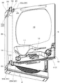
以下、代表的な遊技機であるパチンコ遊技機を例に挙げて本発明の実施の最良の形態を図面に基づき説明する。図1は前面側を開放したパチンコ遊技機の斜視図である。
パチンコ遊技機1は、前方が開放された矩形状の機枠(外枠)2の一側(図1中、左側)に前面枠(内枠)3を開閉可能な状態で軸着し、前面枠3のベースとなる略額縁状の前面枠本体4の表面側には、円形状の遊技領域5が区画形成された遊技盤6を収納し、前面枠本体4の裏面側には、球貯留タンクや球排出装置等の裏面側装備部品7を装着している。また、前面枠本体4の表面側の一側(図1中、左側)には透明部材保持枠9を開閉(回動)可能な状態で軸着し、該透明部材保持枠9に透視可能な透明部材10を収納し、透明部材保持枠9の下部には、遊技球を貯留可能な上皿ユニット11を備えている。そして、透明部材保持枠9を閉じて前面枠本体4の表側に透明部材保持枠9を重合すると、遊技盤6が透明部材保持枠9により被覆されるとともに、透明部材10が遊技領域5の前方に配置され、透明部材10を通して遊技領域5を前方から視認できるように構成されている。また、機枠2に対して前面枠本体4を閉じると、裏面側装備部品7が機枠2内に収容されるように構成されている。さらに、前面枠本体4のうち透明部材保持枠9の下方には、下皿ユニット12を上皿ユニット11とは左右方向にずれた位置に配置し、該下皿ユニット12の左側に灰皿14を備え、下皿ユニット12の右側には、発射装置(図示せず)を操作するための発射操作ユニット(発射操作ハンドル)15を備えている(図3参照)。
Hereinafter, the best mode for carrying out the present invention will be described with reference to the drawings, taking a pachinko gaming machine as a typical gaming machine as an example. FIG. 1 is a perspective view of a pachinko gaming machine with the front side opened.
The
次に、機枠2と前面枠本体4とを軸着するための構成、および前面枠本体4と透明部材保持枠9とを軸着するための構成について説明する。
前面枠本体4は、図2に示すように、当該前面枠本体4の一側(図2(a)中、左側)の上端部および下端部に金属製の回動軸ユニット20(上側回動軸ユニット20a、下側回動軸ユニット20b)をそれぞれ設け、該回動軸ユニット20を介して機枠2へ軸着されており、さらには、回動軸ユニット20を介して当該前面枠本体4の表面側に透明部材保持枠9を軸着している。回動軸ユニット20は、図2(b)に示すように、前面枠本体4の表面から透明部材保持枠9側へ向けて突出した舌片状のベースプレート21を横方向へ延在する姿勢で備え、該ベースプレート21の上部(上面)から第1回動軸23を立設し、ベースプレート21の下部からは第2回動軸24を第1回動軸23と同一直線上に位置する状態で垂下している。
Next, a configuration for pivotally mounting the
As shown in FIG. 2, the
また、透明部材保持枠9の一側(図2(a)中、左側)の上端部および下端部、詳しくは回動軸ユニット20寄りの側部の上端部および下端部には、金属製の第1軸受部26(上側第1軸受部26a、下側第1軸受部26b)を透明部材保持枠9の表面から前面枠本体4とは反対側へ向けてそれぞれ突出し、この突出部分に第1回動軸23が遊嵌可能な第1軸受孔27を上下方向へ貫通している。なお、透明部材保持枠9の上端部に設けられた上側第1軸受部26aの下方には、透明部材保持枠9の表裏方向へ貫通する保持枠切欠部28を回動軸ユニット20の上下高さ(第1回動軸23の上端から第2回動軸24の下端までの距離)よりも十分に広い上下幅で形成するとともに、保持枠切欠部28の側部(図2(a)中、左側部)を外方へ開放し、該保持枠切欠部28に回動軸ユニット20を支障なく挿通できるように構成されている。
Further, an upper end and a lower end on one side of the transparent member holding frame 9 (left side in FIG. 2A), more specifically, an upper end and a lower end on the side near the
さらに、図3に示すように、機枠2の一側(図3中、左側)の上端部および下端部、詳しくは回動軸ユニット20寄りの側部の上端部および下端部には金属製の第2軸受部32(上側第2軸受部32a、下側第2軸受部32b)をそれぞれ設け、該第2軸受部32の前縁部を機枠2の前縁部から前方(前面枠本体4側)へ突出し、この突出部分に第2回動軸24が遊嵌可能な第2軸受孔33を上下方向へ貫通している。なお、上側第2軸受部32aは、機枠2の上辺部2aと回動軸ユニット20側(図1中、左側)の側辺部2bとを連結する連結金具35の前側部を屈曲して形成されている。
Further, as shown in FIG. 3, the upper end and the lower end of one side of the machine frame 2 (left side in FIG. 3), more specifically, the upper end and the lower end of the side near the
そして、パチンコ遊技機1は、透明部材保持枠9の外れ止めとなる構成を備えている。具体的に説明すると、図2(a)および図4に示すように、前面枠本体4の上部のうちベースプレート21よりも遊技盤6寄り(図4中、左寄り)には、横長な平板状の突出部37を透明部材保持枠9側へ向けて突出している。また、透明部材保持枠9のうち突出部37に対向し得る箇所、言い換えると上側第1軸受部26aよりも透明部材10寄り(図4中、左寄り)には、突出部37を遊嵌可能な突出受部38を前面枠本体4側が開放した状態で設け、突出受部38と保持枠切欠部28とを横に並べて連通している。そして、突出部37の突出長さを、前面枠本体4(前面枠3)の表面側と透明部材保持枠9の裏面側とが対向した姿勢で当該突出部37の先端(特に回動軸ユニット20寄りの位置の先端)が突出受部38内へ遊嵌可能となる程度の長さに設定している。したがって、透明部材保持枠9を前面枠本体4に対して十分に重合して閉じた閉状態、あるいは閉状態から前面枠本体4に対して十分に開いた全開状態となるまでの途中の開放途中状態(例えば、前面枠本体4とのなす角が90度未満となる状態)で開くと、図1および図4に示すように、突出部37の先端が突出受部38内へ遊嵌する。また、透明部材保持枠9を全開状態、あるいは開放途中状態よりも大きく開いた状態(例えば、前面枠本体4とのなす角が90度以上となる状態)で開くと、突出部37が突出受部38から外れる。
The
さらに、図5に示すように、第1軸受孔27に第1回動軸23を挿通し、且つ突出受部38内に突出部37を遊嵌した状態では、突出受部38の底面と突出部37の下面との間に隙間d1を形成するとともに、突出受部38の天井面と突出部37の上面との間に隙間d2を形成している。したがって、突出受部38に対して突出部37を支障なく嵌脱することができ、透明部材保持枠9をスムーズに開閉することができるように構成されている。また、隙間d1を形成することにより突出部37が突出受部38内を第1回動軸23の軸方向に沿って移動することを許容しているが、この移動可能となる距離(突出移動許容距離)、すなわち隙間d1の寸法を第1回動軸23の長さよりも短く設定している。この結果、突出部37と突出受部38とが遊嵌している状態では、第1軸受部26が上下方向へガタついたとしても第1回動軸23の先端を越えることがないように、言い換えると第1回動軸23が第1軸受部26から外れないように設定されている。
Further, as shown in FIG. 5, in a state where the
また、パチンコ遊技機1は、前面枠本体4の外れ止めとなる構成をも備えている。具体的に説明すると、図1に示すように、上側第2軸受部32aが設けられた連結金具35のうち、第2軸受部32よりも上辺部2aの左右方向の中央寄りには、前面枠本体4の上方へ向けて延出した延出部42を設けている。そして、該延出部42の延出長さを、機枠2の開放口に前面枠本体4の裏面側を臨ませた姿勢で、当該延出部42の先端が前面枠本体4の上方に位置可能となる程度の長さに設定している。したがって、前面枠本体4を機枠2に対して十分に閉じた閉状態、あるいは閉状態から機枠2に対して十分に開いた全開状態となるまでの途中の開放途中状態(例えば、機枠2とのなす角が90度未満となる状態)で開くと、図1に示すように、延出部42の先端が前面枠本体4の上縁部の一部(詳しくは第2回動軸24の近傍の部分)を上方から被覆する。また、前面枠本体4を全開状態、あるいは開放途中状態よりも大きく開いた状態(例えば、機枠2とのなす角が90度以上となる状態)で開くと、前面枠本体4および透明部材保持枠9が延出部42の下方から外れる。
The
さらに、図5に示すように、第2軸受孔33に第2回動軸24を挿通し、且つ延出部42を前面枠本体4の上方に位置させた状態では、延出部42と前面枠本体4の上部との間(または透明部材保持枠9の上部との間)に隙間d3を形成している。したがって、延出部42が前面枠本体4に干渉することがなく、前面枠本体4をスムーズに開閉することができるように構成されている。また、隙間d3、すなわち延出部42と前面枠本体4との上下離間距離を第2回動軸24の長さよりも短く設定している。したがって、延出部42が前面枠本体4の上縁部の一部を上方から被覆している状態では、回動軸ユニット20が上下方向へガタついたとしても第2回動軸24の先端が第2軸受部32よりも上方へ移動することがないように、言い換えると第2回動軸24が第2軸受部32から外れないように設定されている。
Further, as shown in FIG. 5, in a state where the
このような構成を備えたパチンコ遊技機1において、前面枠本体4に透明部材保持枠9を取り付けるには、まず、図2(a)に示すように、前面枠本体4の前方に透明部材保持枠9を前面枠本体4に対して開放途中状態よりも大きく開いた姿勢(90度以上に開いた状態)に設定する。詳しくは、透明部材保持枠9の軸着端(第1軸受部26側)を回動軸ユニット20の前方に配置するとともに、透明部材保持枠9の自由端(透明部材10を挟んで第1軸受部26とは反対側)を第1軸受部26よりも前面枠本体4から離れた位置であって遊技盤6から側方へ外れた位置に配置する。このように透明部材保持枠9の姿勢を設定したならば、上側回動軸ユニット20aに上側第1軸受部26aを上方から近づけて第1軸受孔27に第1回動軸23を挿通する。このとき、透明部材保持枠9には保持枠切欠部28を形成しているので、透明部材保持枠9と上側回動軸ユニット20aとが干渉する虞がない。さらに、下側回動軸ユニット20bに下側第1軸受部26bを上方から近づけて第1軸受孔27に第1回動軸23を挿通する。この結果、透明部材保持枠9の側部が前面枠本体4の側部に回動自在な状態で軸着される。透明部材保持枠9を前面枠本体4へ軸着したならば、透明部材保持枠9を回動して閉状態へ変換し、前面枠本体4の表面側へ重合する。すると、図5に示すように、突出部37が突出受部38へ遊嵌し、透明部材保持枠9が上方へ移動して第1軸受部26が第1回動軸23から外れること、ひいては透明部材保持枠9が前面枠本体4から外れることを規制する。
In the
透明部材保持枠9を閉状態へ変換したならば、機枠2の前方に前面枠本体4を機枠2に対して開放途中状態よりも大きく開いた姿勢(90度以上に開いた状態であって、図3に示す開き具合よりもさらに開いた状態)に設定する。詳しくは、前面枠本体4の軸着端(回動軸ユニット20側)を第2軸受部32の前方に配置するとともに、前面枠本体4の自由端(遊技盤6を挟んで回動軸ユニット20とは反対側)を回動軸ユニット20よりも機枠2から離れた位置であって機枠2の開放口から側方へ外れた位置に配置する。このように前面枠本体4の姿勢を設定したならば、上側第2軸受部32aに上側回動軸ユニット20aを上方から近づけて第2軸受孔33に第2回動軸24を挿通する。さらに、下側第2軸受部32bに下側回動軸ユニット20bを上方から近づけて第2軸受孔33に第2回動軸24を挿通する。この結果、前面枠本体4の側部が機枠2の側部に回動自在な状態で軸着される。前面枠本体4を機枠2へ軸着したならば、前面枠本体4を閉状態へ変換(回動)して前面枠本体4の裏面側装備部品7を機枠2内へ収容する。すると、延出部42が前面枠本体4の上方に位置し、前面枠本体4が上方へ移動して第2回動軸24が第1軸受部26から外れること、ひいては前面枠本体4が機枠2から外れることを規制する。
If the transparent
このようにして、パチンコ遊技機1は、回動軸ユニット20を介して機枠2と前面枠本体4と透明部材保持枠9とを軸着するので、機枠2と前面枠本体4とを軸着するための構成部品数と、前面枠本体4と透明部材保持枠9とを軸着するための構成部品数とを従来よりも少なく抑えることができる。したがって、機枠2、前面枠本体4(前面枠3)、透明部材保持枠9の軸着機構を簡略化することができ、ひいては、パチンコ遊技機1の製造コストの低減を図ることができる。
In this way, the
また、突出部37の長さを、前面枠本体4の表面側と透明部材保持枠9の裏面側とが対向した姿勢で当該突出部37の先端が突出受部38へ遊嵌可能な長さに設定し、加えて、突出移動許容距離を第1回動軸23の長さよりも短く設定したので、透明部材保持枠9の開き具合を異ならせることで、透明部材保持枠9の着脱を規制することができる。したがって、例えば、遊技店の営業中に透明部材保持枠9を近くの遊技者に当たらない程度、具体的には前面枠本体4となす角が90度未満となる状態(開放途中状態)で開いたときに、透明部材保持枠9が前面枠本体4から誤って外れてしまう不都合がないように設定することができる。なお、透明部材保持枠9を閉じて突出受部38内に突出部37を遊嵌すると、回動軸ユニット20の近傍の隙間を突出部37の突出方向(透明部材保持枠9の表裏方向)に沿ってクランク状に屈曲した状態に設定するので、透明部材保持枠9と前面枠本体4との軸着部の近傍からピアノ線や薄いプラスチック片などの不正部材を侵入させる不正行為を未然に防ぐことができる。
Further, the length of the protruding
そして、延出部42の長さを、機枠2の開放口に前面枠本体4の裏面側を臨ませた姿勢で当該延出部42の先端が前面枠本体4の上方に位置可能な長さに設定し、加えて延出部42と前面枠本体4との上下離間距離を第2回動軸24の長さよりも短く設定したので、前面枠本体4の開き具合を異ならせることで、前面枠本体4の着脱を規制することができる。したがって、例えば、遊技店の営業中に前面枠本体4を近くの遊技者に当たらない程度、具体的には機枠2とのなす角が90度未満となる状態(開放途中状態)で開いたときに、前面枠本体4が機枠2から誤って外れてしまう不都合がないように設定することができる。
The length of the extended
ところで、上記実施形態では、回動軸ユニット20において、第1回動軸23と第2回動軸24とを同一直線上に配置していたが、本発明はこれに限定されない。例えば、第1回動軸23と第2回動軸24とをパチンコ遊技機1の前後方向にずらした状態で備え、前面枠本体4の回動中心線と透明部材保持枠9の回動中心線とがずれるように設定してもよい。また、前面枠本体4の上部のうち回動軸ユニット20の側方に突出部37を設け、透明部材保持枠9の上部のうち第1軸受部26の側方に突出受部38を設けたが、本発明はこれに限定されない。要は、前面枠の表面側と透明部材保持枠9の裏面側とが対向した姿勢で、突出部の先端が突出受部へ遊嵌可能であればどのように設定してもよい。例えば、突出部を前面枠本体4のうち上下両側の回動軸ユニット20の間に突設し、突出受部を透明部材保持枠9のうち上下両側の第1軸受部26の間に設けてもよい。
By the way, in the said embodiment, in the
そして、上記実施形態では、代表的な遊技機であるパチンコ遊技機を例にして説明したが、本発明はこれに限らず、前方が開放された機枠と、遊技盤を収納した前面枠と、透明部材が保持された透明部材保持枠とを備え、機枠内に前面枠の裏面側を収容可能とし、前面枠の表面側に透明部材保持枠を重合して遊技盤を透明部材により被覆可能とした遊技機であればどのような遊技機でもよい。例えば、アレンジボール式遊技機、雀球式遊技機等の遊技機であってもよい。 And in the said embodiment, although it demonstrated taking the case of the pachinko game machine which is a typical game machine, this invention is not restricted to this, The machine frame with which the front was open | released, The front frame which accommodated the game board, A transparent member holding frame that holds the transparent member, the rear side of the front frame can be accommodated in the machine frame, and the game board is covered with the transparent member by superposing the transparent member holding frame on the front side of the front frame Any gaming machine that can be used may be used. For example, a gaming machine such as an arrangement ball type gaming machine or a sparrow ball type gaming machine may be used.
なお、前記した実施の形態は全ての点で例示であって制限的なものではないと考えられるべきである。本発明は、上記した説明に限らず特許請求の範囲によって示され、特許請求の範囲と均等の意味及び範囲内での全ての変更が含まれるものである。 It should be understood that the above-described embodiment is illustrative in all respects and not restrictive. The present invention is not limited to the above description, but is defined by the scope of the claims, and includes all modifications within the scope and meaning equivalent to the scope of the claims.
1 パチンコ遊技機
2 機枠
3 前面枠
4 前面枠本体
6 遊技盤
7 裏面側装備部品
9 透明部材保持枠
20 回動軸ユニット
20a 上側回動軸ユニット
20b 下側回動軸ユニット
21 ベースプレート
23 第1回動軸
24 第2回動軸
26 第1軸受部
26a 上側第1軸受部
26b 下側第1軸受部
27 第1軸受孔
28 保持枠切欠部
32 第2軸受部
32a 上側第2軸受部
32b 下側第2軸受部
33 第2軸受孔
37 突出部
38 突出受部
42 延出部
DESCRIPTION OF
Claims (1)
前記前面枠の一側の上端部および下端部には回動軸ユニットをそれぞれ設け、
該回動軸ユニットは、ベースプレートと、該ベースプレートの上部に立設された第1回動軸と、ベースプレートの下部から垂下された第2回動軸と、を備え、
前記透明部材保持枠の一側の上端部および下端部には、第1軸受孔が開設された第1軸受部をそれぞれ設け、
前記機枠の一側の上端部および下端部には、第2軸受孔が開設された第2軸受部をそれぞれ設け、
前記第1軸受孔に第1回動軸を挿通して前面枠の一側に透明部材保持枠を開閉自在な状態で軸着し、第2軸受孔に第2回動軸を挿通して機枠の一側に前面枠を開閉自在な状態で軸着し、
前記前面枠には、透明部材保持枠側へ向けて突出した突出部を設け、
前記透明部材保持枠には、前面枠の突出部を遊嵌可能な突出受部を設け、
前記突出部は、前面枠の表面側と透明部材保持枠の裏面側とが対向した姿勢で、当該突出部の先端が突出受部へ遊嵌可能な突出長さに設定され、
前記第1軸受孔に第1回動軸を挿通し、且つ突出受部内に突出部を遊嵌した状態で、突出部が突出受部内を第1回動軸の軸方向に沿って移動可能な距離を突出移動許容距離とし、
該突出移動許容距離を第1回動軸の長さよりも短く設定したことを特徴とする遊技機。 A machine frame that is open at the front, a front frame that houses a game board, and a transparent member holding frame that holds a transparent member, and can accommodate equipment on the back side of the front frame inside the machine frame. In a gaming machine in which a transparent member holding frame is superposed on the surface side of the frame so that the game board can be covered with the transparent member,
A rotating shaft unit is provided at each of the upper end and the lower end on one side of the front frame,
The rotation shaft unit includes a base plate, a first rotation shaft erected on the upper portion of the base plate, and a second rotation shaft suspended from the lower portion of the base plate,
The upper and lower ends on one side of the transparent member holding frame are each provided with a first bearing portion having a first bearing hole,
The upper end and the lower end on one side of the machine frame are each provided with a second bearing portion having a second bearing hole,
A first rotating shaft is inserted into the first bearing hole, a transparent member holding frame is pivotally attached to one side of the front frame in a freely openable / closable state, and a second rotating shaft is inserted into the second bearing hole. Attach the front frame to one side of the frame so that it can be opened and closed .
The front frame is provided with a protruding portion that protrudes toward the transparent member holding frame,
The transparent member holding frame is provided with a protrusion receiving portion capable of loosely fitting the protrusion of the front frame,
The protruding portion is set to a protruding length that allows the front end of the protruding portion to be loosely fitted to the protruding receiving portion in a posture in which the front surface side of the front frame and the back surface side of the transparent member holding frame face each other.
The protrusion is movable along the axial direction of the first rotation shaft in a state where the first rotation shaft is inserted into the first bearing hole and the protrusion is loosely fitted in the protrusion reception portion. Let the distance be the protrusion movement allowable distance,
A gaming machine characterized in that the protrusion movement allowable distance is set shorter than the length of the first rotation shaft .
Priority Applications (1)
| Application Number | Priority Date | Filing Date | Title |
|---|---|---|---|
| JP2007214276A JP4832382B2 (en) | 2007-08-21 | 2007-08-21 | Game machine |
Applications Claiming Priority (1)
| Application Number | Priority Date | Filing Date | Title |
|---|---|---|---|
| JP2007214276A JP4832382B2 (en) | 2007-08-21 | 2007-08-21 | Game machine |
Related Child Applications (1)
| Application Number | Title | Priority Date | Filing Date |
|---|---|---|---|
| JP2011182682A Division JP5223100B2 (en) | 2011-08-24 | 2011-08-24 | Game machine |
Publications (2)
| Publication Number | Publication Date |
|---|---|
| JP2009045238A JP2009045238A (en) | 2009-03-05 |
| JP4832382B2 true JP4832382B2 (en) | 2011-12-07 |
Family
ID=40498034
Family Applications (1)
| Application Number | Title | Priority Date | Filing Date |
|---|---|---|---|
| JP2007214276A Expired - Fee Related JP4832382B2 (en) | 2007-08-21 | 2007-08-21 | Game machine |
Country Status (1)
| Country | Link |
|---|---|
| JP (1) | JP4832382B2 (en) |
Families Citing this family (2)
| Publication number | Priority date | Publication date | Assignee | Title |
|---|---|---|---|---|
| JP2015062811A (en) * | 2015-01-14 | 2015-04-09 | 株式会社三洋物産 | Game machine |
| JP2016193285A (en) * | 2016-08-22 | 2016-11-17 | 株式会社三洋物産 | Game machine |
Family Cites Families (4)
| Publication number | Priority date | Publication date | Assignee | Title |
|---|---|---|---|---|
| JPS5259586A (en) * | 1975-11-11 | 1977-05-17 | Nec Corp | Production of mesa type controlling and rectifying element |
| JP3302652B2 (en) * | 1999-02-12 | 2002-07-15 | 株式会社ダイドー | Ball game machine |
| JP3397174B2 (en) * | 1999-06-08 | 2003-04-14 | 豊丸産業株式会社 | Pachinko machine |
| JP2005013510A (en) * | 2003-06-26 | 2005-01-20 | Nk Parts Kogyo:Kk | Hinge mechanism |
-
2007
- 2007-08-21 JP JP2007214276A patent/JP4832382B2/en not_active Expired - Fee Related
Also Published As
| Publication number | Publication date |
|---|---|
| JP2009045238A (en) | 2009-03-05 |
Similar Documents
| Publication | Publication Date | Title |
|---|---|---|
| JP4005747B2 (en) | Door device | |
| JP4920633B2 (en) | Outer mirror | |
| JP4355953B2 (en) | Game machine | |
| US9126111B2 (en) | Portable electronic device | |
| US10576765B2 (en) | Printer door hinge assembly | |
| JP2015182616A (en) | Lid body opening/closing mechanism | |
| JP4832382B2 (en) | Game machine | |
| JPWO2011046042A1 (en) | Glove box for vehicle | |
| JP5666058B2 (en) | Electronics | |
| JP5223100B2 (en) | Game machine | |
| JP4376271B2 (en) | Overhead console device | |
| JP2006346230A (en) | Game machine | |
| JP2017205160A (en) | Washing machine | |
| JP4648090B2 (en) | Automotive console box | |
| JP4393796B2 (en) | Game machine | |
| JP2020084583A (en) | Lid opening/closing structure | |
| JP2008167969A (en) | Game machine | |
| JP5008696B2 (en) | Game machine | |
| JP5417212B2 (en) | Pachinko machine | |
| JP2008105490A (en) | Opening/closing mechanism | |
| JP2007007082A (en) | Game machine | |
| JP6239961B2 (en) | Upper hinge for gaming machine | |
| JP7185654B2 (en) | washing machine | |
| JP7117431B2 (en) | washing machine | |
| JP2008207584A (en) | Overhead console device |
Legal Events
| Date | Code | Title | Description |
|---|---|---|---|
| A621 | Written request for application examination |
Free format text: JAPANESE INTERMEDIATE CODE: A621 Effective date: 20081225 |
|
| A977 | Report on retrieval |
Free format text: JAPANESE INTERMEDIATE CODE: A971007 Effective date: 20110620 |
|
| A131 | Notification of reasons for refusal |
Free format text: JAPANESE INTERMEDIATE CODE: A131 Effective date: 20110628 |
|
| A521 | Written amendment |
Free format text: JAPANESE INTERMEDIATE CODE: A523 Effective date: 20110824 |
|
| TRDD | Decision of grant or rejection written | ||
| A01 | Written decision to grant a patent or to grant a registration (utility model) |
Free format text: JAPANESE INTERMEDIATE CODE: A01 Effective date: 20110913 |
|
| A01 | Written decision to grant a patent or to grant a registration (utility model) |
Free format text: JAPANESE INTERMEDIATE CODE: A01 |
|
| A61 | First payment of annual fees (during grant procedure) |
Free format text: JAPANESE INTERMEDIATE CODE: A61 Effective date: 20110920 |
|
| R150 | Certificate of patent or registration of utility model |
Ref document number: 4832382 Country of ref document: JP Free format text: JAPANESE INTERMEDIATE CODE: R150 Free format text: JAPANESE INTERMEDIATE CODE: R150 |
|
| FPAY | Renewal fee payment (event date is renewal date of database) |
Free format text: PAYMENT UNTIL: 20140930 Year of fee payment: 3 |
|
| FPAY | Renewal fee payment (event date is renewal date of database) |
Free format text: PAYMENT UNTIL: 20140930 Year of fee payment: 3 |
|
| R250 | Receipt of annual fees |
Free format text: JAPANESE INTERMEDIATE CODE: R250 |
|
| R250 | Receipt of annual fees |
Free format text: JAPANESE INTERMEDIATE CODE: R250 |
|
| R250 | Receipt of annual fees |
Free format text: JAPANESE INTERMEDIATE CODE: R250 |
|
| R250 | Receipt of annual fees |
Free format text: JAPANESE INTERMEDIATE CODE: R250 |
|
| R250 | Receipt of annual fees |
Free format text: JAPANESE INTERMEDIATE CODE: R250 |
|
| R250 | Receipt of annual fees |
Free format text: JAPANESE INTERMEDIATE CODE: R250 |
|
| LAPS | Cancellation because of no payment of annual fees |