JP6239961B2 - Upper hinge for gaming machine - Google Patents
Upper hinge for gaming machine Download PDFInfo
- Publication number
- JP6239961B2 JP6239961B2 JP2013253539A JP2013253539A JP6239961B2 JP 6239961 B2 JP6239961 B2 JP 6239961B2 JP 2013253539 A JP2013253539 A JP 2013253539A JP 2013253539 A JP2013253539 A JP 2013253539A JP 6239961 B2 JP6239961 B2 JP 6239961B2
- Authority
- JP
- Japan
- Prior art keywords
- support member
- rotation support
- hinge
- pin
- outer frame
- Prior art date
- Legal status (The legal status is an assumption and is not a legal conclusion. Google has not performed a legal analysis and makes no representation as to the accuracy of the status listed.)
- Active
Links
- 239000011521 glass Substances 0.000 claims description 57
- 229920003002 synthetic resin Polymers 0.000 claims description 7
- 239000000057 synthetic resin Substances 0.000 claims description 7
- 229910000831 Steel Inorganic materials 0.000 claims description 3
- 238000003825 pressing Methods 0.000 claims description 3
- 239000010959 steel Substances 0.000 claims description 3
- 238000004519 manufacturing process Methods 0.000 description 3
- 238000005452 bending Methods 0.000 description 2
- 239000000463 material Substances 0.000 description 1
- 238000000034 method Methods 0.000 description 1
Images


Description
本発明は、パチンコ機等の遊技機の外枠に対し表枠を開閉可能に取り付け、表枠に対しガラス枠を開閉可能に取り付ける遊技機用上部ヒンジに関する。 The present invention relates to an upper hinge for a gaming machine in which a table frame is attached to an outer frame of a gaming machine such as a pachinko machine so that the glass frame can be opened and closed.
パチンコ機等の遊技機には、外枠に対し、遊技盤などの機器を取り付けた表枠が第1ヒンジを介して開閉可能に取り付けられ、表枠に対し遊技盤を覆うガラス枠が第2ヒンジを介して開閉可能に取り付けられる。 In a gaming machine such as a pachinko machine, a table frame attached with a device such as a game board is attached to the outer frame through a first hinge so that it can be opened and closed, and a glass frame covering the game board is attached to the table frame. It can be opened and closed via a hinge.
従来、第1ヒンジ、第2ヒンジともに各種の構造のヒンジが製造され、遊技機に使用されているが、例えば、下記特許文献1には、外枠と表枠間及び表枠とガラス枠間に生じやすい隙間を小さくした構造のヒンジ装置が提案されている。
Conventionally, hinges of various structures have been manufactured for both the first hinge and the second hinge, and are used in gaming machines. For example, in
しかしながら、この従来のヒンジ装置は、第1ヒンジと第2ヒンジが別個に構成されて取り付けられ、各ヒンジに、複数のヒンジピンが取り付けられるため、ヒンジピンの本数が多く、また、ヒンジピンを保持する保持部材が上下摺動可能に取り付けられ、且つそれを上方に付勢するコイルばねが装着されるなど、構造が複雑化し、部品点数が増大している。また、ヒンジ装置の大きさを、比較的大型化する必要があるため、ヒンジ装置用のスペースが遊技機内の左縁部縦方向に相当量必要となるなどの課題があった。 However, in this conventional hinge device, the first hinge and the second hinge are separately configured and attached, and a plurality of hinge pins are attached to each hinge. Therefore, the number of hinge pins is large and the hinge pins are held. The structure is complicated and the number of parts is increased, for example, a member is attached so as to be slidable in the vertical direction and a coil spring that biases the member upward is attached. In addition, since it is necessary to relatively increase the size of the hinge device, there is a problem that a considerable amount of space for the hinge device is required in the vertical direction of the left edge portion in the gaming machine.
そこで、従来、外枠に対し表枠を開閉可能に取り付ける第1ヒンジと表枠に対しガラス枠を開閉可能に取り付ける第2ヒンジの上部ヒンジとを一体に構成した上部ヒンジ装置が、上記特許文献2により提案されている。この上部ヒンジ装置は、表枠の上角部に取り付けられ、複雑な構造のピン受け用ハウジング内に、外枠側ヒンジピンを軸受支持する第1軸受部を摺動可能に配設するとともに、ガラス枠側ヒンジピンを軸受支持する第2軸受部を摺動可能に配設する。さらに、この上部ヒンジ装置の第1軸受部、第2軸受部には、各々ガイドピンが嵌挿され、且つ第1軸受部、第2軸受部をヒンジピンの軸受側に付勢するコイルばねが各々に装着され、ガイドピンを保持するためのカラーがピン受け用ハウジングに取り付けられる。
Therefore, conventionally, an upper hinge device in which a first hinge that attaches a front frame to an outer frame so as to be opened and closed and an upper hinge of a second hinge that attaches a glass frame to the front frame so as to be opened and closed is integrally formed by the above-mentioned
このため、この従来のヒンジ装置は、ピン受け用ハウジングの構造が複雑化するとともに、第1軸受部、第2軸受部、2個のガイドピン、2本のコイルばね、及びカラーなど多くの部品を必要とし、組付工程も多く、製造コストが増大する課題があった。 For this reason, this conventional hinge device has a complicated structure for the pin receiving housing, and has many components such as a first bearing portion, a second bearing portion, two guide pins, two coil springs, and a collar. And there are many assembly processes, and there is a problem that the manufacturing cost increases.
本発明は、上記の点に鑑みてなされたもので、遊技機の外枠に対し表枠を開閉可能に取り付け、表枠に対しガラス枠を開閉可能に取り付けることができ、構造が簡単で、少ない部品点数で構成可能な遊技機用上部ヒンジを提供することを目的とする。 The present invention has been made in view of the above points, and can be attached to the outer frame of the gaming machine so that the table frame can be opened and closed, and the glass frame can be attached to the table frame so that the glass frame can be opened and closed. An object is to provide an upper hinge for a gaming machine that can be configured with a small number of parts.
上記目的を達成するために、本発明の遊技機用上部ヒンジは、遊技機の外枠に対し開閉可能に装着される表枠の上角部に取り付けられ、該外枠に対し表枠を開閉可能に支持し、該表枠に対しガラス枠を開閉可能に支持する遊技機用上部ヒンジにおいて、
上部ヒンジの外殻を形成し、上部に該外枠側の外枠ピンを軸受けする第1軸受部を設け、下部に該ガラス枠側のガラス枠ピンを軸受けする第2軸受部を設けたヒンジ本体と、
該ヒンジ本体内に回動可能に軸支され、該第1軸受部に嵌入された該外枠ピンを回動可能に保持する合成樹脂製の第1回動支持部材と、
該ヒンジ本体内に回動可能に軸支され、該第2軸受部に嵌入された該ガラス枠ピンを回動可能に保持する合成樹脂製の第2回動支持部材と、
該第1回動支持部材と該第2回動支持部材を共通軸として支持する支軸と、
を備え、
該第2回動支持部材にはばね弾性部が一体に設けられ、
該ばね弾性部は、該第1回動支持部材に当接して該第1回動支持部材が該外枠ピンを保持する側に該第1回動支持部材を付勢するとともに、該第2回動支持部材が該ガラス枠ピンを保持する側に該第2回動支持部材を付勢することを特徴とする。
In order to achieve the above object, the upper hinge for a gaming machine according to the present invention is attached to an upper corner portion of a table frame that can be opened and closed with respect to the outer frame of the gaming machine, and the table frame is opened and closed with respect to the outer frame. In an upper hinge for a gaming machine that supports the glass frame so that it can be opened and closed with respect to the front frame,
A hinge in which an outer shell of the upper hinge is formed, a first bearing portion for bearing the outer frame pin on the outer frame side is provided on the upper portion, and a second bearing portion for bearing the glass frame pin on the glass frame side is provided on the lower portion The body,
A first rotation support member made of synthetic resin that is pivotally supported in the hinge main body and rotatably holds the outer frame pin fitted in the first bearing portion;
A second rotation support member made of synthetic resin that is pivotally supported in the hinge body and rotatably holds the glass frame pin fitted in the second bearing portion;
A support shaft that supports the first rotation support member and the second rotation support member as a common shaft;
With
A spring elastic portion is integrally provided on the second rotation support member,
The spring elastic portion abuts on the first rotation support member and biases the first rotation support member toward the side where the first rotation support member holds the outer frame pin, and the second rotation support member The rotation support member biases the second rotation support member toward the side holding the glass frame pin.
この発明によれば、基本的には、ヒンジ本体、第1回動支持部材、第2回動支持部材、及び支軸のみから上部ヒンジを構成することができるので、構造が非常に簡単となり、少ない部品点数で安価に遊技機用上部ヒンジを製造することができる。また、従来の回動支持部材のように別部材としてコイルばねなどのばね部材を取り付ける必要がなく、製造時にばね部材を組み付ける工数を削減し、運搬時などにばね部材が外れたりする不具合を解消するができる。 According to the present invention, basically, the upper hinge can be configured only from the hinge body, the first rotation support member, the second rotation support member, and the support shaft, so the structure becomes very simple, An upper hinge for a gaming machine can be manufactured inexpensively with a small number of parts. In addition, there is no need to attach a spring member such as a coil spring as a separate member unlike conventional rotating support members, reducing the man-hours for assembling the spring member during manufacturing and eliminating the problem of the spring member coming off during transportation. I can do it.
ここで、上記第2回動支持部材には操作レバーを一体に設けることが好ましい。これによれば、操作レバーをもって第2回動支持部材を回動操作すれば、容易にガラス枠を傾動させてガラス枠ピンを外すことができる。また、第1回動支持部材の端部には操作部を上記ヒンジ本体から露出した状態で設けることが好ましい。これによれば、第1回動支持部材の操作部を持って第1回動支持部材を回動操作すれば、外枠ピンが第1軸受部から外れ、表枠を傾けて外枠ピンとの係合を外すことができる。 Here, it is preferable that an operation lever is provided integrally with the second rotation support member. According to this, if the second rotation support member is rotated with the operation lever, the glass frame pin can be easily tilted to remove the glass frame pin. Moreover, it is preferable to provide the operation part in the state exposed from the said hinge main body at the edge part of the 1st rotation support member. According to this, if the first rotation support member is rotated by holding the operation portion of the first rotation support member, the outer frame pin comes off from the first bearing portion, and the front frame is tilted to contact the outer frame pin. The engagement can be disengaged.
また、ここで、上記第1回動支持部材には、上記第2回動支持部材のばね弾性部が係合する係合凹部を設けるとともに、該係合凹部とは上記支軸に対し反対側の縁部に、該第2回動支持部材と係合する係合凸部を設けることが好ましい。 Further, here, the first rotation support member is provided with an engagement recess that engages with the spring elastic portion of the second rotation support member, and the engagement recess is opposite to the support shaft. It is preferable to provide an engagement convex portion that engages with the second rotation support member at the edge portion of the first rotation support member.
これによれば、簡単な構造により、第1回動支持部材には、第1軸受部に嵌入された外枠ピンを回動可能に保持させ、第2回動支持部材には、第2軸受部に嵌入されたガラス枠ピンを回動可能に保持させるように、第1回動支持部材と第2回動支持部材を動作させることができる。 According to this, with a simple structure, the first rotation support member holds the outer frame pin fitted in the first bearing portion in a rotatable manner, and the second rotation support member has the second bearing. The first rotation support member and the second rotation support member can be operated so that the glass frame pin fitted in the portion is rotatably held.
また、上記ヒンジ本体は鋼板をプレス加工して形成され、上記表枠の上角部に取り付けるための直角取付面を有する直角取付部を、ヒンジ本体に設けるとともに、ヒンジ本体の正面側の先端部に、内部をカバーするカバー部を設けることができる。これによれば、カバー部が正面位置で、ヒンジ本体内の第1回動支持部材及び第2回動支持部材をカバーするため、第1回動支持部材または第2回動支持部材を不正に動かすなどの不正行為を防止することができる。 The hinge body is formed by pressing a steel plate, and a right angle mounting portion having a right angle mounting surface for mounting on the upper corner of the front frame is provided on the hinge body, and a front end portion on the front side of the hinge body Further, a cover portion that covers the inside can be provided. According to this, since the cover portion covers the first rotation support member and the second rotation support member in the hinge body at the front position, the first rotation support member or the second rotation support member is illegally covered. Unauthorized actions such as moving can be prevented.
本発明の遊技機用上部ヒンジによれば、構造が簡単で、少ない部品点数で構成することができ、遊技機の外枠側の外枠ピンに対し表枠の上角部を簡単に着脱可能に軸支させることができるともに、表枠に対しガラス枠側のガラス枠ピンを簡単に着脱可能に軸支されることができる。 According to the upper hinge for gaming machine of the present invention, the structure is simple, it can be configured with a small number of parts, and the upper corner of the table frame can be easily attached to and detached from the outer frame pin on the outer frame side of the gaming machine. The glass frame pin on the glass frame side can be easily and detachably supported with respect to the front frame.
以下、本発明の実施の形態を図面に基づいて説明する。図1〜図3はパチンコ機などに使用される遊技機用上部ヒンジの斜視図を示し、その上部ヒンジ1は、遊技機の全体構成を示す図13のように、遊技機の表枠51の上角部に取り付けられるヒンジ器具である。
Hereinafter, embodiments of the present invention will be described with reference to the drawings. 1 to 3 are perspective views of an upper hinge for a gaming machine used in a pachinko machine or the like, and the
この上部ヒンジ1は、図10に示すように、その外殻を形成し、上部に外枠ピン8aを軸受けする第1軸受部21に設け、下部にガラス枠ピン9aを軸受けする第2軸受部22を設けたヒンジ本体2と、ヒンジ本体2内に回動可能に軸支され、第1軸受部21に嵌入された外枠ピン8aを回動可能に保持する合成樹脂製の第1回動支持部材3と、ヒンジ本体2内に回動可能に軸支され、第2軸受部22に嵌入されたガラス枠ピン9aを回動可能に保持する合成樹脂製の第2回動支持部材4と、第1回動支持部材3と第2回動支持部材4を共通軸として支持する支軸5と、を備えて構成される。
As shown in FIG. 10, the
上記外枠ピン8aは、図13に示す如く、遊技機の外枠50の上角部に取り付けられる外枠側ヒンジ8に下向きに突設され、上記ガラス枠ピン9aは遊技機のガラス枠52の上角部に取り付けられるガラス枠側ヒンジ9に上向きに突設される。
As shown in FIG. 13, the
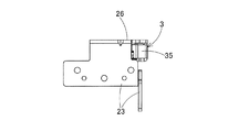
上部ヒンジ1のヒンジ本体2は、図10に示すように、鋼板をプレス加工により曲折して形成され、遊技機の表枠51の上角部に取り付けるために、その背面側に直角取付部23が設けられる。さらに、直角取付部23から正面側に突出するように、水平突出部25が設けられ、水平突出部25には第1軸受部21及び第2軸受部22が設けられる。直角取付部23は取付板を直角に曲折して形成され、一方の取付板に固定ねじ用の複数のねじ孔が設けられる。
As shown in FIG. 10, the
水平突出部25の内側には、第1回動支持部材3と第2回動支持部材4が、1本の縦方向の支軸5により回動可能に軸支される。ヒンジ本体2の水平突出部25には、上平面板部26が上面水平方向に延設され、上平面板部26の左側面に側壁部28が略直角に曲折して設けられる。側壁部28から上平面板部26にかけて、鈎型に曲折した溝状の第1軸受部21が、その開口部から内側に導入される外枠ピン8aを奥部の軸受部まで受入れ可能に形成される。第1軸受部21は、曲折したガイド溝の終端部まで外枠ピン8aを導入して、終端部に設けた半円形の軸受部で軸受けし、第1回動支持部材3の先端のピン支持部34により、外枠ピン8aを回動可能に軸受部で保持する構造となっている。
Inside the
また、ヒンジ本体2の水平突出部25の正面には、カバー部24が、上平面板部26の前端部を直角に曲折して先端部をカバーするように設けられる。さらに、側壁部28から内側に曲折するように下平面板部27が設けられ、この下平面板部27には、鈎状に曲折した溝状の第2軸受部22が、その内部にガラス枠ピン9aを受入れ可能に形成される。第2軸受部22は、曲折したガイド溝の終端部までガラス枠ピン9aを導入して終端部に設けた半円形の軸受部で軸受けし、回動可能に軸支した第2回動支持部材4の先端のピン支持部44により、その軸受部でガラス枠ピン9aを回動可能に支持する構造となっている。
Further, a
第1回動支持部材3及び第2回動支持部材4は、各々、合成樹脂材料により一体成形される。第1回動支持部材3は、上記のように、外枠ピン8aが第1軸受部21の曲折したガイド溝の終端部まで進入したとき、先端のピン支持部34により、付勢力をもって外枠ピン8aを回動可能に支持するように動作する。そのために、第2回動支持部材4に一体にばね弾性部41が設けられ、このばね弾性部41により、外枠ピン8aを支持する方向つまり第1軸受部21を閉じる側に付勢されるようになっている。
The first
なお、図11に示すように、第1回動支持部材3の元部(ピン支持部34と反対側)には、外枠ピン8aを外す際、第1回動支持部材3を回動操作するための操作部35が設けられ、この操作部35は、図7に示すように、ヒンジ本体2の切欠部から露出し、回動操作が可能である。
As shown in FIG. 11, when the
一方、第2回動支持部材4は、ガラス枠ピン9aが第2軸受部22の曲折したガイド溝の終端部まで進入したとき、先端のピン支持部44により、付勢力をもってガラス枠ピン9aを回動可能に支持するように動作する。そのために、第2回動支持部材4は、ばね弾性部41を介して第1回動支持部材3からばね弾性の反力を受け、ガラス枠ピン9aを支持する方向つまり第2軸受部22を閉じる側に付勢される。
On the other hand, when the
第1回動支持部材3と第2回動支持部材4は、図10に示すように、1本の共通軸としての支軸5により、共に回動可能に軸支されるが、図12に示すように、第2回動支持部材4は第1回動支持部材3の下側に抱き込むように挿入され、第2回動支持部材4の端部のばね弾性部41が第1回動支持部材3の係合凹部31内に入りその内側の当接面31aに、図3に示す如く当接する。
As shown in FIG. 10, the first
これにより、第1回動支持部材3は、図7、図11の時計方向つまり第1軸受部21を閉じる方向に付勢され、第2回動支持部材4は、ばね弾性部41を介して第1回動支持部材3から反力を受けるように、図11の反時計方向つまり第2軸受部22を閉じる方向に付勢される。
Accordingly, the first
また、図8〜図12に示すように、第1回動支持部材3の下縁部には、係合凸部32が突設され、第1回動支持部材3の下側に挿入される第2回動支持部材4の側部がこの係合凸部32に当接した状態となる。これにより、第1回動支持部材3と第2回動支持部材4がヒンジ本体2の内側に挿入されて支軸5により回動可能に軸支された状態で、図7、図8に示す如く、第1回動支持部材3の先端のピン支持部34は、第1軸受部21を閉じて外枠ピン8aを軸受可能とし、第2回動支持部材4の先端のピン支持部44は、第2軸受部22を閉じてガラス枠ピン9aを軸受可能とするようになっている。
Further, as shown in FIGS. 8 to 12, an engaging
なお、図7、図8に示すように、第1回動支持部材3と第2回動支持部材4はヒンジ本体2の内側定位置に挿入されて支軸5により回動可能に軸支された状態で、第1回動支持部材3の操作部35はヒンジ本体2の切欠端部に当接し、第2回動支持部材4の凸部45はヒンジ本体2の切欠端部に当接して、図1〜図3に示す如く定位置に保持される構造である。
As shown in FIGS. 7 and 8, the first
このように、上記構成の上部ヒンジ1は、ヒンジ本体2、第1回動支持部材3、第2回動支持部材4、及び支軸5のみから構成されるので、構造が非常に簡単となり、少ない部品点数で安価に遊技機用上部ヒンジを製造することができる。また、従来の回動支持部材のように別部材としてコイルばねなどのばね部材を取り付ける必要がなく、製造時にばね部材を組み付ける工数を削減し、運搬時などにばね部材が外れたりする不具合を解消するができる。
As described above, the
上記構成の上部ヒンジ1は、図13に示すように、遊技機の表枠51の上角部に、直角取付部23を用いてその水平突出部25を前方に突き出す形態で固定される。表枠51が開閉可能に装着される外枠50の上角部には、外枠側ヒンジ8が固定され、外枠側ヒンジ8には、外枠ピン8aが下向きに突設される。なお、図13に示すように、外枠50の下角部には、下部ヒンジ53が取り付けられ、下部ヒンジ53上には、下部ヒンジピン53aが上向きに突設される。表枠51の下角部には、下部ヒンジ54が固定され、下部ヒンジ54には下部ヒンジ軸受(軸孔)54aが設けられている。
As shown in FIG. 13, the
遊技機の外枠50の前面に、表枠51を開閉可能に取り付ける場合、図13のように、先ず、表枠51の下部ヒンジ54の下部ヒンジ軸受54aを、外枠50の下部ヒンジ53の下部ヒンジピン53aに、上から嵌入するように嵌め込み、次に、表枠51を傾けて、その上角部の上部ヒンジ1の第1軸受部21を、外枠50の外枠側ヒンジ8の外枠ピン8aに嵌め込むように動かす。このとき、外枠ピン8aが上部ヒンジ1の水平突出部25の側壁部28に設けた開口から第1軸受部21内に進入する。なお、図13では表枠51及びガラス枠52が閉鎖(角度)状態で図示されているが、実際に表枠51またはガラス枠52を着脱する場合、表枠51及びガラス枠52を開放した状態で、着脱操作は行なわれる。
When the
このとき、第1回動支持部材3の先端部が外枠ピン8aに押されて、図7の反時計方向に回動し、第1回動支持部材3が第1軸受部21のガイド溝から内側に外れ、外枠ピン8aはガイド溝を通りその終端部の第1軸受部21まで到達する。これに伴い、第1回動支持部材3がばね弾性部41の付勢力により元の位置(図7の位置)に戻り、第1軸受部21のガイド溝を閉じて、第1回動支持部材3のピン支持部34が外枠ピン8aを第1軸受部21内で回動可能に支持する状態となり、外枠ピン8aは第1軸受部21内で回動可能に軸支される。
At this time, the distal end portion of the first
表枠51の前面に、ガラス枠52を開閉可能に取り付ける場合、図13のように、先ず、ガラス枠52の下部ヒンジ55の下部ヒンジ軸受55aを、表枠51の中間ヒンジ56の中間ヒンジピン56aに、上から嵌入するように嵌め込み、次に、ガラス枠52を傾けて、表枠51の上角部の上部ヒンジ1の第2軸受部22に、ガラス枠52のガラス枠側ヒンジ9のガラス枠ピン9aを嵌め込むように動かす。このとき、ガラス枠ピン9aが上部ヒンジ1の下平面板部27に設けた開口からガイド溝を通り第2軸受部22内に進入する。
When the
このとき、第2回動支持部材4の先端部がガラス枠ピン9aに押されて、図8の反時計方向(ばね弾性部41の付勢力に抗する方向)に回動し、第2回動支持部材4が第2軸受部22のガイド溝から内側に外れ、ガラス枠ピン9aはガイド溝を通りその終端部の第2軸受部22まで到達する。これに伴い、第2回動支持部材4はばね弾性部41の付勢力により元の位置(図8の位置)に戻り、第2軸受部22のガイド溝を閉じて、第2回動支持部材4のピン支持部44がガラス枠ピン9aを第2軸受部22内で回動可能に支持する状態となり、ガラス枠ピン9aは第2軸受部22内で回動可能に軸支される。
At this time, the distal end portion of the second
一方、表枠51の上部ヒンジ1を外枠側ヒンジ8から外す場合、第1回動支持部材3の元部の操作部35を持って図1の矢印A方向(図7の反時計方向に)に、第1回動支持部材3を回動させる。これにより、第1回動支持部材3のピン支持部34が第1軸受部21のガイド溝から外れ、外枠ピン8aは第1軸受部21から離脱可能な状態となって、上部ヒンジ1が外枠側ヒンジ8から外される。
On the other hand, when the
一方、ガラス枠52のガラス枠側ヒンジ9を上部ヒンジ1から外す場合、操作レバー42を持って図3(図8)の矢印B方向に、第2回動支持部材4を回動させる。このとき、第2回動支持部材4がばね弾性部41の付勢力に抗して、図8の反時計方向に回動し、これにより、第2回動支持部材4のピン支持部44が第2軸受部22のガイド溝から外れ、ガラス枠ピン9aは第2軸受部22から離脱可能な状態となって、ガラス枠側ヒンジ9は表枠51の上角部の上部ヒンジ1から外される。
On the other hand, when the glass
このように、第2回動支持部材4に操作レバー42が一体に設けられ、操作レバー42をもって第2回動支持部材4を一方向に回動操作すれば、容易にガラス枠52を傾けてガラス枠ピン9aを外すことができる。また、第1回動支持部材3の操作部35を持って第1回動支持部材3を他方向に回動操作すれば、外枠ピン8aが第1軸受部21から外れ、表枠51の上角部の上部ヒンジ1を、外枠側ヒンジ8から外すことができる。
As described above, the
1 上部ヒンジ
2 ヒンジ本体
3 第1回動支持部材
4 第2回動支持部材
5 支軸
8 外枠側ヒンジ
8a 外枠ピン
9 ガラス枠側ヒンジ
9a ガラス枠ピン
21 第1軸受部
22 第2軸受部
23 直角取付部
24 カバー部
25 水平突出部
26 上平面板部
27 下平面板部
28 側壁部
31 係合凹部
31a 当接面
32 係合凸部
34 ピン支持部
35 操作部
41 弾性部
42 操作レバー
44 ピン支持部
45 凸部
50 外枠
51 表枠
52 ガラス枠
53 下部ヒンジ
53a 下部ヒンジピン
54 下部ヒンジ
54a 下部ヒンジ軸受
55 下部ヒンジ
55a 下部ヒンジ軸受
56 中間ヒンジ
56a 中間ヒンジピン
DESCRIPTION OF
Claims (5)
上部ヒンジの外殻を形成し、上部に該外枠側の外枠ピンを軸受けする第1軸受部を設け、下部に該ガラス枠側のガラス枠ピンを軸受けする第2軸受部を設けたヒンジ本体と、
該ヒンジ本体内に回動可能に軸支され、該第1軸受部に嵌入された該外枠ピンを回動可能に保持する合成樹脂製の第1回動支持部材と、
該ヒンジ本体内に回動可能に軸支され、該第2軸受部に嵌入された該ガラス枠ピンを回動可能に保持する合成樹脂製の第2回動支持部材と、
該第1回動支持部材及び該第2回動支持部材を共通軸として支持する支軸と、
を備え、
該第2回動支持部材にはばね弾性部が一体に設けられ、
該ばね弾性部は、該第1回動支持部材に当接して該第1回動支持部材が該外枠ピンを保持する側に該第1回動支持部材を付勢するとともに、該第2回動支持部材が該ガラス枠ピンを保持する側に該第2回動支持部材を付勢することを特徴とする遊技機用上部ヒンジ。 Attached to the upper corner of a table frame that can be opened and closed with respect to the outer frame of the gaming machine, supports the table frame so that it can be opened and closed, and supports the glass frame so that it can be opened and closed with respect to the outer frame. In the upper hinge for gaming machines,
A hinge in which an outer shell of the upper hinge is formed, a first bearing portion for bearing the outer frame pin on the outer frame side is provided on the upper portion, and a second bearing portion for bearing the glass frame pin on the glass frame side is provided on the lower portion The body,
A first rotation support member made of synthetic resin that is pivotally supported in the hinge main body and rotatably holds the outer frame pin fitted in the first bearing portion;
A second rotation support member made of synthetic resin that is pivotally supported in the hinge body and rotatably holds the glass frame pin fitted in the second bearing portion;
A support shaft that supports the first rotation support member and the second rotation support member as a common shaft;
With
A spring elastic portion is integrally provided on the second rotation support member,
The spring elastic portion abuts on the first rotation support member and biases the first rotation support member toward the side where the first rotation support member holds the outer frame pin, and the second rotation support member An upper hinge for a gaming machine, wherein the rotation support member biases the second rotation support member toward the side holding the glass frame pin.
Priority Applications (1)
| Application Number | Priority Date | Filing Date | Title |
|---|---|---|---|
| JP2013253539A JP6239961B2 (en) | 2013-12-06 | 2013-12-06 | Upper hinge for gaming machine |
Applications Claiming Priority (1)
| Application Number | Priority Date | Filing Date | Title |
|---|---|---|---|
| JP2013253539A JP6239961B2 (en) | 2013-12-06 | 2013-12-06 | Upper hinge for gaming machine |
Publications (2)
| Publication Number | Publication Date |
|---|---|
| JP2015109926A JP2015109926A (en) | 2015-06-18 |
| JP6239961B2 true JP6239961B2 (en) | 2017-11-29 |
Family
ID=53525363
Family Applications (1)
| Application Number | Title | Priority Date | Filing Date |
|---|---|---|---|
| JP2013253539A Active JP6239961B2 (en) | 2013-12-06 | 2013-12-06 | Upper hinge for gaming machine |
Country Status (1)
| Country | Link |
|---|---|
| JP (1) | JP6239961B2 (en) |
Families Citing this family (1)
| Publication number | Priority date | Publication date | Assignee | Title |
|---|---|---|---|---|
| JP6077071B1 (en) * | 2015-08-21 | 2017-02-08 | 株式会社新太陽 | Game machine |
Family Cites Families (3)
| Publication number | Priority date | Publication date | Assignee | Title |
|---|---|---|---|---|
| JP4817941B2 (en) * | 2006-04-05 | 2011-11-16 | 株式会社ニューギン | Game machine |
| JP5249142B2 (en) * | 2008-12-19 | 2013-07-31 | 次夫 近藤 | Hinge device for pachinko machine |
| JP5398281B2 (en) * | 2009-01-21 | 2014-01-29 | 株式会社Mrd | Hinge mechanism of gaming machine |
-
2013
- 2013-12-06 JP JP2013253539A patent/JP6239961B2/en active Active
Also Published As
| Publication number | Publication date |
|---|---|
| JP2015109926A (en) | 2015-06-18 |
Similar Documents
| Publication | Publication Date | Title |
|---|---|---|
| JP5547921B2 (en) | Electronic keyboard instrument keyboard device | |
| JP2011134188A (en) | Electronic apparatus | |
| JP6239961B2 (en) | Upper hinge for gaming machine | |
| US8506024B2 (en) | Electronic apparatus | |
| JP2006346230A (en) | Game machine | |
| JP5748809B2 (en) | Music stand for grand piano | |
| JP2008002111A (en) | Hinge mechanism for cover | |
| JP4947541B2 (en) | Game machine | |
| JP2022125796A5 (en) | ||
| JP2002035348A (en) | Pachinko game machine | |
| JP3901642B2 (en) | Pachinko machine | |
| JP3940129B2 (en) | Pachinko machine | |
| JP2009045238A (en) | Game machine | |
| JP2003334359A (en) | Hinge for game machine | |
| JP7117431B2 (en) | washing machine | |
| JP5413794B2 (en) | Keyboard instrument | |
| JP5720417B2 (en) | Lid support device | |
| WO2019193794A1 (en) | Washing machine | |
| JP7172424B2 (en) | electronic keyboard instrument | |
| JP5641277B2 (en) | Keyboard device | |
| JP4286606B2 (en) | Hinge for game console | |
| JP5660290B2 (en) | Keyboard instrument | |
| JP6407008B2 (en) | Latch device | |
| JP2013219486A (en) | Cover lock mechanism for electronic apparatus and electronic apparatus with the same | |
| JP2020014543A (en) | Upper hinge for game machine |
Legal Events
| Date | Code | Title | Description |
|---|---|---|---|
| A621 | Written request for application examination |
Free format text: JAPANESE INTERMEDIATE CODE: A621 Effective date: 20161205 |
|
| A977 | Report on retrieval |
Free format text: JAPANESE INTERMEDIATE CODE: A971007 Effective date: 20170925 |
|
| TRDD | Decision of grant or rejection written | ||
| A01 | Written decision to grant a patent or to grant a registration (utility model) |
Free format text: JAPANESE INTERMEDIATE CODE: A01 Effective date: 20171003 |
|
| A61 | First payment of annual fees (during grant procedure) |
Free format text: JAPANESE INTERMEDIATE CODE: A61 Effective date: 20171102 |
|
| R150 | Certificate of patent or registration of utility model |
Ref document number: 6239961 Country of ref document: JP Free format text: JAPANESE INTERMEDIATE CODE: R150 |
|
| R250 | Receipt of annual fees |
Free format text: JAPANESE INTERMEDIATE CODE: R250 |
|
| S531 | Written request for registration of change of domicile |
Free format text: JAPANESE INTERMEDIATE CODE: R313532 |
|
| R350 | Written notification of registration of transfer |
Free format text: JAPANESE INTERMEDIATE CODE: R350 |
|
| R250 | Receipt of annual fees |
Free format text: JAPANESE INTERMEDIATE CODE: R250 |