JP6812875B2 - Tape cassette - Google Patents
Tape cassette Download PDFInfo
- Publication number
- JP6812875B2 JP6812875B2 JP2017061393A JP2017061393A JP6812875B2 JP 6812875 B2 JP6812875 B2 JP 6812875B2 JP 2017061393 A JP2017061393 A JP 2017061393A JP 2017061393 A JP2017061393 A JP 2017061393A JP 6812875 B2 JP6812875 B2 JP 6812875B2
- Authority
- JP
- Japan
- Prior art keywords
- printing
- protective film
- medium
- tape cassette
- roller
- Prior art date
- Legal status (The legal status is an assumption and is not a legal conclusion. Google has not performed a legal analysis and makes no representation as to the accuracy of the status listed.)
- Active
Links
Images


Classifications
-
- B—PERFORMING OPERATIONS; TRANSPORTING
- B41—PRINTING; LINING MACHINES; TYPEWRITERS; STAMPS
- B41J—TYPEWRITERS; SELECTIVE PRINTING MECHANISMS, i.e. MECHANISMS PRINTING OTHERWISE THAN FROM A FORME; CORRECTION OF TYPOGRAPHICAL ERRORS
- B41J15/00—Devices or arrangements of selective printing mechanisms, e.g. ink-jet printers or thermal printers, specially adapted for supporting or handling copy material in continuous form, e.g. webs
- B41J15/04—Supporting, feeding, or guiding devices; Mountings for web rolls or spindles
- B41J15/044—Cassettes or cartridges containing continuous copy material, tape, for setting into printing devices
Description
本発明は、テープカセットに関するものである。 The present invention relates to a tape cassette.
従来、長尺な帯状の被印刷媒体に対し、任意の文字、図形、絵等の印刷を行ってから印刷部分を被印刷媒体から切り離すことで、印刷物としてのラベルを作成する印刷装置(ラベルプリンタ)及びこれに用いられる被印刷媒体を備えたテープカセットが知られている。
こうしたラベルプリンタで作成されるラベルの耐久性を高めるためには、印刷部によって印刷が施された印刷面がラミネートフィルム等の保護フィルムによって保護されていることが好ましい。
Conventionally, a printing device (label printer) that creates a label as a printed matter by printing arbitrary characters, figures, pictures, etc. on a long strip-shaped print medium and then separating the printed portion from the print medium. ) And the tape cassette provided with the printing medium used for this are known.
In order to increase the durability of the label produced by such a label printer, it is preferable that the printed surface printed by the printing unit is protected by a protective film such as a laminated film.
この点、例えば特許文献1には、ラベルプリンタにおいて、長尺な透明フィルムに印刷を行った後、印刷面側に両面粘着テープを貼り合わせることで印刷面を保護することができるラミネートタイプのテープカセットを用いる構成が提案されている。 In this regard, for example, in Patent Document 1, in a label printer, a laminated type tape capable of protecting the printed surface by printing on a long transparent film and then adhering a double-sided adhesive tape to the printed surface side. A configuration using a cassette has been proposed.
しかしながら、特許文献1に記載のラベルプリンタのように複数のテープを貼り合わせてラベルを作成するタイプのラベルプリンタの場合には、各テープは、貼り合わされた後に再剥離が困難な状態になる。
このため、例えば、テープの印刷開始位置を調整しようとしても、一旦テープ同士を貼り合わせた後は、これを巻き戻そうとすると、ローラによって巻取り動作を行ったときにテープカセットの中でテープが詰まったり引っかかる等、ジャムを生じてテープカセットが使えなくなるおそれもあり、また印刷装置の故障の原因ともなり得る。
However, in the case of a type of label printer such as the label printer described in Patent Document 1 in which a plurality of tapes are bonded to create a label, each tape is in a state of being difficult to be peeled off again after being bonded.
Therefore, for example, even if the printing start position of the tape is adjusted, if the tapes are once bonded to each other and then rewound, the tape is wound in the tape cassette when the winding operation is performed by the roller. There is a risk that the tape cassette cannot be used due to jamming such as clogging or catching, and it may also cause a malfunction of the printing apparatus.
本発明は以上のような事情に鑑みてなされたものであり、被印刷媒体と保護フィルムとを有するテープカセットにおいて、被印刷媒体と保護フィルムとの貼り合わせ状態を印刷装置により制御することができる利点を有するものである。 The present invention has been made in view of the above circumstances, and in a tape cassette having a print medium and a protective film, the bonding state of the print medium and the protective film can be controlled by a printing apparatus. It has advantages.
前記課題を解決するために、本発明のテープカセットは、
テープカセットであって、
印刷装置により印刷が行われる印刷面を有する被印刷媒体と、
接着剤が一方の面側に設けられた保護フィルムと、
前記被印刷媒体の前記印刷面と前記保護フィルムの前記一方の面側に設けられた前記接着剤とが対向して配置される位置に、前記印刷装置の可動部に接離可能に設けられ、前記印刷装置の前記可動部が前記被印刷媒体及び前記保護フィルムの一方を他方に押すように前記テープカセットの外部から押圧力を加えて圧着させるとき、前記印刷装置の前記可動部と、前記被印刷媒体及び前記保護フィルムとの間に介在し、前記押圧力を前記被印刷媒体へ伝える介在部材と、を備えることを特徴とする。
In order to solve the above problems, the tape cassette of the present invention is used.
It ’s a tape cassette,
A printable medium having a printing surface on which printing is performed by a printing device,
A protective film with adhesive on one side,
The printing surface of the printing medium and the adhesive provided on one surface side of the protective film are arranged so as to face each other, and are provided in contact with and detachable from the movable portion of the printing device . When the movable portion of the printing device presses one of the printing medium and the protective film against the other by applying a pressing force from the outside of the tape cassette, the movable portion of the printing device and the cover are pressed. It is characterized by comprising an intervening member interposed between the print medium and the protective film and transmitting the pressing force to the printable medium.
本発明によれば、被印刷媒体と保護フィルムとを有するテープカセットにおいて、被印刷媒体と保護フィルムとの貼り合わせ状態を印刷装置により制御することができる。 According to the present invention, in a tape cassette having a print medium and a protective film, the bonding state of the print medium and the protective film can be controlled by a printing apparatus.
図1から図21を参照しつつ、本発明に係るテープカセットの一実施形態について説明する。
なお、以下に述べる実施形態には、本発明を実施するために技術的に好ましい種々の限定が付されているが、本発明の範囲を以下の実施形態及び図示例に限定するものではない。
An embodiment of the tape cassette according to the present invention will be described with reference to FIGS. 1 to 21.
Although the embodiments described below are provided with various technically preferable limitations for carrying out the present invention, the scope of the present invention is not limited to the following embodiments and illustrated examples.
図1は、本実施形態に係るテープカセットが適用される印刷装置の外観を示す斜視図であり、図2は、印刷装置の開閉蓋を開放した状態を示す斜視図である。
なお、本実施形態において、被印刷媒体M(印刷テープ)の搬送される方向を「搬送方向X」とし、この搬送方向Xに直交する被印刷媒体M(印刷テープ)の幅方向を「媒体幅方向Y」とし、被印刷媒体M(印刷テープ)の厚み方向を「厚み方向Z」とする。これらX方向、Y方向、及びZ方向は、互いに直交する。
FIG. 1 is a perspective view showing the appearance of a printing apparatus to which the tape cassette according to the present embodiment is applied, and FIG. 2 is a perspective view showing a state in which the opening / closing lid of the printing apparatus is opened.
In the present embodiment, the transport direction of the printable medium M (printing tape) is defined as the “conveyance direction X”, and the width direction of the printable medium M (printing tape) orthogonal to the transport direction X is the “medium width”. The direction Y is defined, and the thickness direction of the print medium M (printing tape) is defined as the thickness direction Z. These X, Y, and Z directions are orthogonal to each other.
図1に示す印刷装置1は、長尺な帯状の被印刷媒体Mに印刷を行う印刷部の一例であるサーマルヘッド11を備え、例えばシングルパス方式で印刷を行うラベルプリンタである。被印刷媒体Mは、例えば、粘着面Msを有する基材Maと、粘着面Msを覆う剥離可能な剥離紙Mbとを有するテープ部材である(図5(a)及び図5(b)参照)。
本実施形態では、後述するように、基材Maの粘着面Msとは反対側の面(基材Maの表面。これを「印刷面MP」とする。図5(a)及び図5(b)参照)に印刷部であるサーマルヘッド11により印刷が行われる。なお、以降では、インクリボンを使用する熱転写方式のラベルプリンタを例にして説明するが、印刷方式は特に限定されず、例えば、感熱紙を使用する感熱方式であってもよい。
また、本実施形態では、後述するように、印刷部(本実施形態ではサーマルヘッド11)による印刷後、基材Maの表面である印刷面MPにラミネートフィルム等の保護フィルムFを貼着するようになっている。
以下においては、印刷前の被印刷媒体Mを被印刷媒体M1とし、印刷後保護フィルムFが貼着された状態の被印刷媒体Mを被印刷媒体M2(印刷物)とする。なお、印刷や保護フィルムFの貼着等の加工の前後を特に問わないときは単に被印刷媒体M(印刷テープ)ともいう。
なお、本実施形態では、被印刷媒体M2(印刷物)の一例として文字列等が印刷されたラベル(なお、長尺な被印刷媒体Mが切断されて単位印刷物となったものをラベルL(図21参照)とする。)を示して説明する。
The printing device 1 shown in FIG. 1 is a label printer including a
In the present embodiment, as will be described later, the surface of the base material Ma opposite to the adhesive surface Ms (the surface of the base material Ma. This is referred to as “printing surface MP”. FIGS. 5 (a) and 5 (b). ) Is printed by the
Further, in the present embodiment, as will be described later, after printing by the printing unit (
In the following, the printed medium M before printing is referred to as the printed medium M1, and the printed medium M in which the protective film F is attached after printing is referred to as the printed medium M2 (printed matter). In addition, when it does not matter before and after processing such as printing and sticking of the protective film F, it is simply referred to as a print medium M (printing tape).
In the present embodiment, as an example of the printed medium M2 (printed matter), a label on which a character string or the like is printed (note that a long printed medium M is cut into a unit printed matter is labeled L (FIG. FIG. 21) will be described.
《テープカセットの構成》
まず、図3から図7及び図7(b)を参照しつつ、本実施形態におけるテープカセット5について説明する。
図2に示すように本実施形態のテープカセット5は、印刷装置1のカセット収納部24に、テープカセット5における媒体幅方向Yを縦にした状態で着脱自在に収納される。
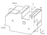
図3は、本実施形態におけるテープカセットの外観を示す斜視図であり、図4は、図3に示すテープカセットからカセットケースの上ケースを取り外してテープカセット5の内部を示した斜視図である。なお、図4ではテープカセット5内から被印刷媒体M、インクリボンR及び保護フィルムFを取り外した状態を図示している。また、図5(a)は、テープカセット内の各ローラに被印刷媒体M、インクリボンR及び保護フィルムFが巻回された状態を模式的に示した平面図である。また、図5(b)は、被印刷媒体Mの断面図であり、図5(c)は、保護フィルムFの断面図である。
<< Composition of tape cassette >>
First, the
As shown in FIG. 2, the
FIG. 3 is a perspective view showing the appearance of the tape cassette according to the present embodiment, and FIG. 4 is a perspective view showing the inside of the
テープカセット5は、図3から図5(a)に示すように、サーマルヘッド被挿入部511が形成されたカセットケース51を備えている。このカセットケース51は、下ケース51aと上ケース51bとを嵌め合わせることで形成されている。
サーマルヘッド被挿入部511は、テープカセット5を印刷装置1のカセット収納部24に収納した際に、サーマルヘッド11に対応する位置に形成された凹部である。
As shown in FIGS. 3 to 5 (a), the
The thermal
カセットケース51内には、印刷テープローラ52、インクリボン供給ローラ53、とインクリボン巻取りローラ54、保護フィルムローラ55が設けられている。
印刷テープローラ52は、前述のように駆動軸241と係合されており、搬送用モータ制御回路108によって制御されるステッピングモータ118によって駆動する駆動ローラである。
印刷テープローラ52の媒体幅方向Yの端部にはフランジ521が設けられており、全体的にボビン形状となっている。印刷テープローラ52には被印刷媒体Mがロール状に巻回されている。
本実施形態では、後述するように印刷動作前に搬送用モータ制御回路108の制御により被印刷媒体Mを巻き戻す動作を行うが、印刷テープローラ52の端部にフランジ521が設けられていることにより、被印刷媒体Mを巻き戻した際に被印刷媒体Mがずれにくく、円滑な巻き戻しが可能となる。
A
The
A
In the present embodiment, as will be described later, the operation of rewinding the print medium M is performed under the control of the transport
また、熱転写用のインクリボンRは、その先端がインクリボン巻取りローラ54に巻きつけられた状態で、インクリボン供給ローラ53にロール状に巻回されている。
インクリボン巻取りローラ54は、駆動軸242と係合されており、搬送用モータ制御回路108によって制御されるステッピングモータ118によって駆動する駆動ローラである。
Further, the ink ribbon R for thermal transfer is wound around the ink
The ink ribbon take-up
また、保護フィルムローラ55は、駆動軸243と係合されており、搬送用モータ制御回路108によって制御されるステッピングモータ118によって駆動する駆動ローラである。
印刷テープローラ52と同様に、保護フィルムローラ55の媒体幅方向Yの端部にはフランジ551が設けられており、全体的にボビン形状となっている。保護フィルムローラ55には保護フィルムFがロール状に巻回されている。
本実施形態における保護フィルムFは、図5(c)に示すように、押圧力の程度により復元可能な程度の仮圧着状態と復元不能な程度の本圧着状態とを取り得る接着剤FPが基材Gの一方の面に設けられており、仮圧着の状態では再剥離可能な再剥離型のフィルムとなっている。保護フィルムFは、例えばラミネートフィルム等であるが、これに限定されない。
本実施形態では、後述するように、保護フィルムFは、仮圧着ローラ56等で構成される仮圧着部において印刷後の被印刷媒体Mにおける印刷面MP上に押圧され復元可能な程度の仮圧着状態となる。
本実施形態では、印刷動作前に被印刷媒体Mを巻き戻す動作を行う際に、被印刷媒体Mにおける基材Maの印刷面MP上に仮圧着されている保護フィルムFもともに巻き戻すが、保護フィルムローラ55の端部にフランジ551が設けられていることにより、保護フィルムFを巻き戻した際に保護フィルムFがテープ幅方向にずれにくく、円滑な巻き戻しが可能となる。
Further, the
Similar to the
As shown in FIG. 5C, the protective film F in the present embodiment is based on an adhesive FP that can be in a temporarily crimped state that can be restored depending on the degree of pressing force and a main crimped state that cannot be restored. It is provided on one surface of the material G, and is a re-peelable film that can be re-peelable in the state of temporary pressure bonding. The protective film F is, for example, a laminated film or the like, but is not limited thereto.
In the present embodiment, as will be described later, the protective film F is temporarily crimped to the extent that it can be restored by being pressed onto the printing surface MP of the printing medium M after printing at the temporary crimping portion composed of the temporary crimping
In the present embodiment, when the operation of rewinding the printing medium M is performed before the printing operation, the protective film F temporarily pressure-bonded on the printing surface MP of the base material Ma in the printing medium M is also rewound. Since the
また、保護フィルムローラ55よりも被印刷媒体Mの搬送方向下流側であって後述するプラテンユニット12の突出部124に対応する位置には、仮圧着ローラ56が設けられている。
本実施形態では、被印刷媒体Mの印刷面MPとは逆側(すなわち、剥離紙Mb側)から被印刷媒体Mを押圧する第1の押圧部材としての突出部124と、被印刷媒体Mの印刷面MP側の固定された位置に設けられていて、被印刷媒体Mの印刷面MP側から保護フィルムFに接し、突出部124により被印刷媒体Mが剥離紙Mb側から押圧されることにより被印刷媒体Mを押圧する第2の押圧部材としての仮圧着ローラ56とにより仮圧着部が構成されている。
仮圧着ローラ56は、本圧着ローラ17による押圧力よりも弱い力で保護フィルムFを被印刷媒体Mにおける基材Maの印刷面MPに押圧し、再剥離可能な状態で仮固定する。
仮圧着ローラ56の回転軸561には、搬送用モータ制御回路108によって制御されるステッピングモータ118が接続されており、仮圧着ローラ56は、搬送用モータ制御回路108の制御に応じて回転駆動する駆動ローラである。
Further, a temporary crimping
In the present embodiment, the projecting
The temporary crimping
A stepping
カセットケース51における、仮圧着ローラ56とプラテンユニット12の突出部124との間となる位置には、透明な樹脂等の透明材料で形成された透明プレート57が、被印刷媒体Mのテープ幅方向に延在して配置されている。
この透明プレート57は、被印刷媒体Mの裏面(すなわち、剥離紙Mbの設けられている面)に対向する面を備える板状の形状を有する部材である。
透明プレート57は、被印刷媒体Mの印刷面MPと保護フィルムFの一方の面側に設けられた接着剤FPとが対向して配置される位置において、印刷装置1が被印刷媒体M及び保護フィルムFの一方を他方に押すように押圧力を加えて圧着させるとき、被印刷媒体M及び保護フィルムFと、印刷装置1との間に介在している介在部材である。
介在部材である透明プレート57は、被印刷媒体Mの印刷面MPと保護フィルムFにおける接着剤FPとが対向して配置される箇所において、被印刷媒体Mの印刷面MPと反対側の裏面(すなわち、剥離紙Mbの設けられている面)と対向する位置に設けられ、被印刷媒体Mの裏面に接触可能で、印刷面MPの面方向と交差する方向(図6において上下方向)に移動可能となっている。
より具体的には、この透明プレート57は、第1の押圧部材である突出部124と第2の押圧部材である仮圧着ローラ56との間に配置可能とされた介在部材であり、突出部124と第2の押圧部材である仮圧着ローラ56との間に介在し、第1の押圧部材である突出部124の押圧力を被印刷媒体Mに伝える押圧板である。
At a position in the
The
In the
The
More specifically, the
図6は、仮圧着部の突出部124及び仮圧着ローラ56と介在部材である透明プレート57を拡大した要部拡大図である。
図6に示すように、透明プレート57は、カセットケース51の一部のプレート挿入部を構成する部材58における、内側に突出した突起58bで構成される挿入空間58c内に挿入されており、透明プレート57の厚さは挿入空間58cの高さより小さく、透明プレート57の横幅は、この挿入空間58cのの横幅より小さく、且つ、対向する突起58bの間の幅より大きく、これにより透明プレート57は挿入空間58c内にとどまるとともに、挿入空間58c内において少なくとも上下に自由に動けるようになっている。このため、透明プレート57は、突出部124より押圧力を受けていないときには、その自重で被印刷媒体Mの裏面上に乗っているだけであり、実質的に被印刷媒体Mを保護フィルムFに押しつけてはいない状態となっている。一方、透明プレート57は、突出部124より押圧力を受けているときには、その押圧力により、被印刷媒体Mを保護フィルムFに押しつける状態になる。
図6に示すように、印刷時には、被印刷媒体Mがこの透明プレート57と仮圧着ローラ56との間に搬送される。透明プレート57はプラテンユニット12の突出部124によって仮圧着ローラ56の側に押圧されており、被印刷媒体Mの基材Maと保護フィルムFとは透明プレート57と仮圧着ローラ56との間で押圧されることにより、仮固定される。
FIG. 6 is an enlarged view of a main part of the protruding
As shown in FIG. 6, the
As shown in FIG. 6, at the time of printing, the printing medium M is conveyed between the
なお、後述するテープ先端検出センサ16は透明プレート57に対応する位置に配置されている。
透明プレート57は、被印刷媒体Mの裏面と対向する側とは反対側から、当該透明プレート57を介して被印刷媒体Mを視認可能とする透過性を有している。これによりテープ先端検出センサ16はテープカセット5側の部材等に遮られることなく、透明プレート57の下を通過する被印刷媒体Mの先端部を検出することができる。
The tape
The
なお、本実施形態では、保護フィルムFを備えないテープカセット5も適用することが可能となっている。この場合、介在部材として透明プレート57を備えると、透明プレート57が突出部124によって仮圧着ローラ56の側に押圧されることで被印刷媒体Mの搬送を円滑に行うことができない。
このため、本実施形態では、介在部材として、保護フィルムFが使用されないとき、透明プレート57に代えて、被印刷媒体Mを印刷装置1から加えられる押圧力を受けない状態(すなわち、被印刷媒体Mを第1の押圧部材としての突出部124の押圧力を受けない状態)で通過させる枠状部材59が用意されている。
保護フィルムFが使用されないときには、この枠状部材59を透明プレート57に代えて配置することにより、被印刷媒体Mの搬送を円滑に行うことができる。
本実施形態において、透明プレート57と枠状部材59とは保護フィルムFの有無に応じて選択的に装着可能となっている。
In this embodiment, the
Therefore, in the present embodiment, when the protective film F is not used as the intervening member, the printing medium M is not subjected to the pressing force applied from the printing device 1 instead of the transparent plate 57 (that is, the printing medium). A frame-shaped
When the protective film F is not used, the frame-shaped
In the present embodiment, the
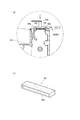
図7(a)は、突出部124と仮圧着ローラ56との間に介在部材として枠状部材59を配置した状態を示す要部拡大図であり、図7(b)は、枠状部材59の斜視図である。
枠状部材59は、透明プレート57と同様に透明な樹脂等の透明材料で形成されており、挿入空間58c内に設けられ、その厚さは挿入空間58cの高さより小さく、その横幅は挿入空間58cのの横幅より小さく、且つ、対向する突起58bの間の幅より大きく、透明プレート57と同様に、挿入空間58c内にとどまるとともに、挿入空間58c内において少なくとも上下に自由に動けるようになっている。
枠状部材59は、被印刷媒体Mのテープ幅方向に延在して配置されており、延在方向と直交する被印刷媒体Mの搬送方向に沿って挿通する挿通溝部591を有している。
保護フィルムFを備えないテープカセット5を用いて印刷を行う場合には、図7(a)に示すように、被印刷媒体Mが枠状部材59の挿通溝部591内に挿通され、突出部124の押圧力を受けずに通過できるようにする。
なお、枠状部材59は、透明プレート57と同様に、被印刷媒体Mの裏面と対向する側とは反対側から、当該枠状部材59を介して被印刷媒体Mを視認可能とする透過性を有している。
これにより、枠状部材59を設けた場合でも、テープ先端検出センサ16はテープカセット5側の部材等に遮られることなく、枠状部材59の挿通溝部591内を通過する被印刷媒体Mの先端部を検出することができる。
FIG. 7A is an enlarged view of a main part showing a state in which the frame-shaped
The frame-shaped
The frame-shaped
When printing is performed using the
Similar to the
As a result, even when the frame-shaped
また、本実施形態では、筐体2のカセット収納部24内に、テープカセット5の種類(テープカセット5の内部に収められている被印刷媒体M(印刷テープ)の種類)を検出するためのテープ種類検出センサ18が配置されており、カセットケース51には、テープ種類検出センサ18によって検出される図示しない識別マーク等が付されている。
なお、識別マーク等はテープ種類検出センサ18によって読み取り可能なものであればよく、例えばカセットケース51の外側に形成された凹凸である。この場合には、テープ種類検出センサ18は凹凸の配置やパターンを読み取ることでテープの種類を検出する。なお、識別マーク等は立体的なものに限定されず、例えばバーコードのようなものでもよい。この場合にはテープ種類検出センサ18としてバーコードリーダを備える。なお、テープカセット5に付される識別マーク等及びこれを読み取るテープ種類検出センサ18の構成はここに例示したものに限定されない。
Further, in the present embodiment, in order to detect the type of the tape cassette 5 (the type of the printable medium M (printing tape) housed inside the tape cassette 5) in the
The identification mark or the like may be any one that can be read by the tape
《印刷装置の構成》
次に、図1、図2等を参照しつつ、本実施形態の印刷装置1の構成について詳説する。
図1に示すように、印刷装置1は、筐体2と、この筐体2に開閉自在に取り付けられた開閉蓋3とを備えている。図2に示すように、筐体2は、内部に後述するテープカセット5を収容するカセット収納部24を備えている。
筐体2の上面には、電源ボタン21の他、各種操作を行う操作ボタン22、開閉蓋3を開放させる蓋開閉ボタン23等が配置されている。
外部電源D(図12参照)が接続されている状態(すなわちACアダプタ接続状態)で電源ボタン21が押下されると、電源回路107(図12参照)に信号が送られて印刷装置1の電源がONとなる。
また、操作ボタン22や蓋動作ボタン23が押下されると、操作入力制御回路106(図12参照)に信号が送られて各ボタン操作に応じた処理が行われる。
なお、本実施形態の蓋開閉ボタン23は、開閉蓋3を開放させるだけのものであり、開閉蓋3を閉じる際にはユーザが手動にて開閉蓋3を閉じる。
また、図示はしないが、筐体2には、電源コード接続端子、外部機器接続端子、記憶媒体挿入口等が設けられている。なお、印刷装置1が電池等の内部電源で動作するものである場合には、電源コード接続端子はなくてもよい。また、印刷装置1がパーソナルコンピュータや各種の端末装置等の外部機器との接続を行わずに使用するものである場合や、外部機器と無線で接続可能に構成されている場合には、外部機器接続端子を備えていなくてもよい。
<< Configuration of printing device >>
Next, the configuration of the printing apparatus 1 of the present embodiment will be described in detail with reference to FIGS. 1, 2 and the like.
As shown in FIG. 1, the printing apparatus 1 includes a
In addition to the
When the
Further, when the
The lid opening /
Further, although not shown, the
開閉蓋3は、カセット収納部24の上部を覆うように開閉可能に配置されている。開閉蓋3は、蓋開閉ボタン23が押下されることにより開放される。
本実施形態において、開閉蓋3の内側面(すなわち、カセット収納部24側の面)には、筐体2内部に突出する突起部31が設けられており、開閉蓋3が閉じられた際にこの突起部31に対応する部分には、突起部31を検知する蓋開閉センサ25が設けられている。蓋開閉センサ25により開閉蓋3が閉じられたことが検出されると、検出結果が後述する本体制御装置10のセンサ入力回路113(図12参照)に出力される。
また、開閉蓋3の内側面(すなわち、カセット収納部24側の面)には、筐体2内部に突出する係止爪32が設けられており、開閉蓋3が閉じられた際にこの係止爪32に対応する部分には、係止爪32を係止させる係止凹部26が設けられている。開閉蓋3が閉じられると、係止爪32が係止凹部26に係止され、誤って開閉蓋3が開放されない状態となる。開閉蓋3が閉じられているときに蓋開閉ボタン23が押下されると、操作入力制御回路106(図12参照)にこれに応じた信号が出力されて、図示しない動作機構により係止爪32の係止状態が解除されて、開閉蓋3が開放される。
また、開閉蓋3には、この開閉蓋3が閉じた状態でもカセット収納部24にテープカセット5(図3から図5(a)参照)が収納されているか否かを目視で確認可能とするために、窓部33が形成されている。
さらに、開閉蓋3の内側面(すなわち、カセット収納部24側の面)には、カセット収納部24にテープカセット5が収容された際にこれを押えるカセット押え34が設けられている。カセット押え34は、開閉蓋3が閉められた状態においてテープカセット5を上方から押えてテープカセット5の位置ずれや浮き上がり等を防ぐようになっている。なお、テープカセット5は、その内部に装着されている被印刷媒体M1(印刷テープ)の幅によって厚みが異なり、カセット収納部24に収容された際の上面の高さが異なる。このため、各種の高さに対応可能であるように、カセット押え34は多少のバネ性を有する構成となっていることが好ましい。
The opening /
In the present embodiment, the inner side surface of the opening / closing lid 3 (that is, the surface on the
Further, a locking
Further, the opening /
Further, on the inner side surface of the opening / closing lid 3 (that is, the surface on the
また、開閉蓋3の内側面(すなわち、カセット収納部24側の面)には、筐体2内部に突出する押圧突起部28が設けられている。押圧突起部28の先端部は、楔型に切り欠かれている(図11(a)〜図11(d)参照)。
開閉蓋3が閉じられた際にこの押圧突起部28の先端部に対応する部分には、押圧突起部28が挿入される開口部29が形成されている。開口部29の下方(図2において下方)には、後述する本圧着ローラ17(上側ローラ17a)を動作させる動作軸部173が配置されるようになっており、後述するように、押圧突起部28が開口部29内に挿入されることで動作軸部173が動作して本圧着ローラ17(上側ローラ17a)を動作させるようになっている(図8(a)及び図8(b)から図11(a)〜図11(d)参照)。
Further, on the inner side surface of the opening / closing lid 3 (that is, the surface on the
An
カセット収納部24内には、内部に収容されたテープカセット5の種類(テープカセット5の内部に収められている被印刷媒体M(印刷テープ)の種類)を検出するためのテープ種類検出センサ18(図12参照)が配置されている。
テープ種類検出センサ18は、例えば、テープカセット5のカセットケース51(図3及び図4参照)に付された識別マーク等を読み取ることで、当該テープカセット5の内部に収められている被印刷媒体M(印刷テープ)の幅等のテープ種類を検出するようになっている。
テープ種類検出センサ18によって検出された検出結果は、センサ入力回路113に出力され、これにより印刷装置1の本体制御装置10は筐体2内に収納されているテープカセット5の種類を自動的に取得することができる。なお、テープ種類検出センサ18はテープカセット5の種類を識別できるものであればよく、具体的な配置、構成等は特に限定されない。
Inside the
The tape
The detection result detected by the tape
また、カセット収納部24内であって後述するテープカセット5の印刷テープローラ52、インクリボン巻取りローラ54、保護フィルムローラ55の軸中心に対応する位置に、それぞれ駆動軸241,242,243が設けられている。
すなわち、カセット収納部24内にテープカセット5を収納した状態において、駆動軸241には印刷テープローラ52が係合し、駆動軸242にはインクリボン巻取りローラ54が係合し、駆動軸243には保護フィルムローラ55が係合する。
これら駆動軸241,242,243には、後述する搬送用モータ制御回路108によって制御されるステッピングモータ118が接続されており、搬送用モータ制御回路108の制御に応じて回転駆動するようになっている。これにより駆動軸241,242,243に係合している印刷テープローラ52、インクリボン巻取りローラ54、保護フィルムローラ55が回転する。
Further, drive
That is, in a state where the
A stepping
また、カセット収納部24内には、本実施形態における印刷部としてのサーマルヘッド11が配置されている。
サーマルヘッド11は、搬送部を構成するプラテンローラ122等により搬送される被印刷媒体Mの搬送経路上に配置され、当該被印刷媒体Mに印刷を行う印刷部である。
サーマルヘッド11は、例えば、主走査方向(被印刷媒体M1(印刷テープ)の搬送方向Xに直交する媒体幅方向Y)に配列された複数の発熱素子を有する。サーマルヘッド11は、後述するヘッド制御回路112(図12参照)の制御により、印刷データに応じて複数の発熱素子が選択的に通電されることで、熱転写により被印刷媒体Mに一ラインずつ印刷を行う。
Further, in the
The
The
印刷時に被印刷媒体Mを挟んでこのサーマルヘッド11に対応する位置には、プラテンユニット12(図5(a)、図14〜図19等参照)が設けられている。プラテンユニット12は、昇降用モータ116(図12参照)によって昇降するプラテンユニット昇降機構125(図12参照)により、サーマルヘッド11に対して接離する方向に昇降するようになっている。
プラテンユニット昇降機構125の具体的な構成は特に限定されないが、例えば、図1に示すように、プラテンユニット12における被印刷媒体Mの搬送方向Xの上流側に設けられた回動軸121を昇降用モータ116(図12参照)によって動作させることにより、この回動軸121を支点としてプラテンユニット12全体が回動するようになっている。
なお、本実施形態においてプラテンユニット昇降機構125の動作は、開閉蓋3の開閉と同期している。
すなわち、開閉蓋3が閉じられたことを蓋開閉センサ25が検出すると、昇降用モータ116を制御する昇降用モータ制御回路110(図12参照)がプラテンユニット12をサーマルヘッド11側に近づける方向に昇降用モータ116を制御する。また、開閉蓋3が開放されたことを蓋開閉センサ25が検出すると、昇降用モータ制御回路110(図12参照)がプラテンユニット12をサーマルヘッド11から離間する方向に昇降用モータ116を制御する。
A platen unit 12 (see FIGS. 5 (a), 14 to 19 and the like) is provided at a position corresponding to the
The specific configuration of the platen
In this embodiment, the operation of the platen
That is, when the lid open /
本実施形態では、プラテンユニット12内であって、印刷時にサーマルヘッド11と対向する位置には、プラテンローラ122(図5(a)、図14〜図19等参照)が配置されている。本実施形態のプラテンローラ122は、被印刷媒体Mの媒体幅方向Yに延在してプラテンユニット12内に設けられている回転軸123に軸支されている。回転軸123は後述する搬送用モータ制御回路108(図12参照)により制御されるステッピングモータ114により回転駆動するようになっており、プラテンローラ122は回転軸123が回転することにより図1に示す矢印方向に回転する。
開閉蓋3が閉じてプラテンユニット12がサーマルヘッド11側に近づいた際には、プラテンローラ122蓋開閉ボタンが被印刷媒体Mを介してサーマルヘッド11に当接し、サーマルヘッド11が被印刷媒体Mに対してほぼ均一な力で接するように押圧しながら一定の速度で被印刷媒体Mを搬送方向Xに搬送するようになっている。
なお、本実施形態では、後述するように、印刷開始前に被印刷媒体Mを巻き戻すようになっており、この巻き戻し時には、開閉蓋3の開閉に関わりなく、プラテンユニット12をサーマルヘッド11から離間する方向に動作させ、プラテンローラ122が被印刷媒体Mを介してサーマルヘッド11に当接しないように昇降用モータ116を制御する。これにより、被印刷媒体Mの巻き戻し時にプラテンローラ122が抵抗とならず、円滑に巻き戻し動作を行うことができる。
In the present embodiment, the platen roller 122 (see FIGS. 5 (a), 14 to 19 and the like) is arranged in the
When the opening /
In the present embodiment, as will be described later, the print medium M is rewound before the start of printing. At the time of rewinding, the
さらに、本実施形態では、プラテンユニット12における被印刷媒体Mの搬送方向Xの下流側であって、後述する仮圧着ローラ56に対応する位置には、仮圧着ローラ56に対して被印刷媒体Mを押圧する突出部124(図5(a)、図6、図14〜図19等参照)が設けられている。
突出部124の形状等は特に限定されないが、被印刷媒体Mを仮圧着ローラ56に対してできるだけ均一な力で押圧することができるように、被印刷媒体Mの媒体幅方向Yにある程度長く延在する板状の部材であるか、もしくは被印刷媒体Mの媒体幅方向Yに複数配置されたボスであることが好ましい。また、突起部15として複数のボスを設ける場合には、できるだけ押圧力に偏りが生じないように、ほぼ等間隔でボスを配置することが好ましい。
Further, in the present embodiment, the printed medium M is located downstream of the transport direction X of the printed medium M in the
The shape of the protruding
被印刷媒体Mの搬送経路上であって、サーマルヘッド11よりも搬送方向Xの下流側であり、後述の仮圧着部と本圧着部との間には、印刷後の帯状の被印刷媒体Mを切断して単位印刷物に切り分ける切断部13(図14〜図19等参照)が設けられている。
切断部13には、フルカット機構14とハーフカット機構15とが含まれている。
切断部13において切断される被印刷媒体Mは、表面側に印刷面MPを有し印刷面MPとは逆側の面に粘着面Msを有する基材Maと、基材Maの粘着面Ms側に重畳される剥離紙Mbとを備えている。また、本実施形態では、印刷後に、基材Maの印刷面MP側に保護フィルムFを貼り合わせるようになっており、切断部13には、保護フィルムF、基材Ma、剥離紙Mbの3層からなる被印刷媒体M2が搬送される。
ここで、フルカット機構14によって行われるフルカットとは、被印刷媒体Mの保護フィルムF、基材Maを剥離紙Mbとともに媒体幅方向Yに沿って切断する動作のことであり、ハーフカット機構15によって行われるハーフカットとは、被印刷媒体Mのうち剥離紙Mbを残して保護フィルムF及び基材Maのみを媒体幅方向Yに沿って切断する動作のことである。
It is on the transport path of the print medium M, downstream of the
The cutting
The printing medium M to be cut in the cutting
Here, the full cut performed by the
切断部13におけるフルカット機構14及びハーフカット機構15は、それぞれ被印刷媒体Mの切断位置まで下降するカッター141,151を備えている。すなわち、フルカット機構14のカッター141は、保護フィルムF、基材Ma、剥離紙Mbの3層すべてを切断する厚み方向Zの位置まで下降する。また、ハーフカット機構15のカッター151は、保護フィルムF及び基材Maの2層のみを切断する厚み方向Zの位置まで下降する。
フルカット機構14及びハーフカット機構15のカッター141,151は、後述するカッターモータ制御回路111により動作制御されるカッターモータ117(図12参照)によって、被印刷媒体Mに対して接離する方向に動作するようになっている。
カッター141,151の下降位置はカッターモータ制御回路111によるカッターモータ117の制御によって行われてもよいし、ハーフカット機構15に、保護フィルムF及び基材Maの2層のみを切断する厚み方向Zの位置でカッター151が停止しそれ以上下降しないように、図示しないストッパが設けられていてもよい。
The full-
The
The lowering positions of the
被印刷媒体Mの搬送経路上であって、仮圧着部である突出部124・仮圧着ローラ56と、本圧着部である本圧着ローラ17(17a,17b)との間には、被印刷媒体Mにおける搬送方向Xの先端部(搬送方向先端部)を検出するテープ先端検出センサ16(図14〜図19等参照)が設けられている。
テープ先端検出センサ16によって検出された検出結果は、本体制御装置10のセンサ入力回路113に出力される。
On the transport path of the medium M to be printed, the projecting
The detection result detected by the tape
また、仮圧着ローラ56及び切断部13よりも被印刷媒体Mの搬送経路の下流側には、一対の本圧着ローラ17(上側ローラ17a及び下側ローラ17b)が配置されている。
本圧着ローラ17は印刷後の基材Maの表面(すなわち、印刷面MP)に保護フィルムFを圧着固定するものである。
本実施形態の保護フィルムFは、一定以上の圧力を加えることで元の状態に戻らない程度に貼着(本圧着)されるが、これよりも弱い力で押圧しても仮固定(仮圧着)されるだけで元に戻すことができ、貼り直しが可能な再剥離型の接着剤FPが基材Gの一方の面に設けられているフィルムである。本実施形態では、仮圧着ローラ56を通過した時点で保護フィルムFが基材Maの表面(すなわち、印刷面MP)に仮固定(仮圧着)され、本圧着ローラ17による押圧により本圧着されるようになっている。
本圧着ローラ17は、上側ローラ17a及び下側ローラ17b、又はそのいずれか一方が、排出用モータ制御回路109により制御されるステッピングモータ115と接続されており、ステッピングモータ115により回転駆動する駆動ローラである。
なお、本実施形態では、上側ローラ17aは下側ローラ17bに対して接離する方向に移動可能となっている。
Further, a pair of main crimping rollers 17 (
The crimping
The protective film F of the present embodiment is attached (mainly crimped) to the extent that it does not return to its original state by applying a certain pressure or more, but it is temporarily fixed (temporarily crimped) even if it is pressed with a weaker force than this. ) Is a film in which a removable adhesive FP that can be restored and reattached is provided on one surface of the base material G. In the present embodiment, the protective film F is temporarily fixed (temporarily crimped) to the surface of the base material Ma (that is, the printing surface MP) when it passes through the temporary crimping
In the crimping
In the present embodiment, the
ここで、上側ローラ17aを下側ローラ17bに対して接離する方向に移動させる構成について説明する。
図8(a)、図9(a)、図10(a)は、印刷装置1の筐体内であって本圧着ローラ17が設けられている部分を示す要部平面図であり、図示の都合上、本来は筐体2の内壁部分の下方にあって視認できない上側ローラ17aを下側ローラ17b及び上側ローラ17aを動作させる機構を実線で示している。
図8(b)、図9(b)、図10(b)は、それぞれ図8(a)、図9(a)、図10(a)に対応する上側ローラ17aの動作状態を示した平面図である。
また、図11(a)から図11(d)は、開閉蓋3側に設けられている押圧突起部28の動きと、これにより動作する上側ローラ17aの動作軸部173との関係を示す説明図である。
なお、図9(a)、図10(a)及び図11(b)から図11(d)では、動作軸部173の初期位置(押圧突起部28に押されていない状態においてとる位置、図8(a)、図11(a)参照)を二点鎖線で示している。
図8(a)及び図8(b)等に示すように、本実施形態において、本圧着ローラ17のうち上側ローラ17aは、コイルバネ171が取り付けられたローラ支持軸172に支持されている。コイルバネ171は、押し縮められることで上側ローラ17aを下側ローラ17bに対して押圧する付勢部材である。
ローラ支持軸172には、支点174を回動中心として搖動する動作軸部173が取り付けられている。動作軸部173の一端側はコイルバネ171と接しており、支点174を回動中心として搖動することで、動作軸部173の一端側においてコイルバネ171を押し縮めたり開放したりする。
動作軸部173の他端側は、図11(a)に示すように、前述の開口部29の下方に位置しており、開閉蓋3が閉じられることで押圧突起部28が開口部29内に挿入されると、押圧突起部28の先端部に押圧されて動作軸部173が動作するようになっている。
Here, a configuration for moving the
8 (a), 9 (a), and 10 (a) are plan views of a main part showing a portion of the housing of the printing apparatus 1 in which the crimping
8 (b), 9 (b), and 10 (b) are planes showing the operating states of the
11 (a) to 11 (d) show the relationship between the movement of the
9 (a), 10 (a), and 11 (b) to 11 (d) show the initial position of the operation shaft portion 173 (position taken when not pressed by the pressing protrusion 28). 8 (a) and FIG. 11 (a)) are shown by alternate long and short dash lines.
As shown in FIGS. 8A and 8B, in the present embodiment, the
An operating
As shown in FIG. 11A, the other end side of the operating
具体的には、図11(b)及び図11(c)に示すように、押圧突起部28の先端部が開口部29内に挿入されると、押圧突起部28の先端部の傾斜面に押されて、動作軸部173が徐々にスライド移動する。これにより、動作軸部173の初期位置(図8(a)及び図11(a)参照)においては図8(b)に示すように上側ローラ17aが下側ローラ17bから離間していた状態から、徐々に上側ローラ17aが下側ローラ17bを押圧した状態となる。
そして、図11(d)に示すように、開閉蓋3が閉じられて、押圧突起部28の先端部が完全に開口部29内に挿入されると、図10(a)及び図10(b)、に示すように、コイルバネ171が強く押し縮められて、上側ローラ17aが下側ローラ17bに密着した状態となる。
Specifically, as shown in FIGS. 11B and 11C, when the tip of the
Then, as shown in FIG. 11D, when the opening /
筐体2の側面であって被印刷媒体Mの搬送方向Xの下流側に位置する部分には、排出口27が形成されている。印刷装置1内においてサーマルヘッド11による印刷が完了した被印刷媒体Mは、本圧着ローラ17により押圧されることで保護フィルムFが基材Maの表面(すなわち、印刷面MP)に圧着固定されるとともに、排出口27から装置外へと排出される。
A
《印刷装置の制御構成》
次に、本実施形態における印刷装置1の制御構成について説明する。
図12は、印刷装置1の制御構成を示すブロック図である。
図12に示すように、印刷装置1は、上述の各種ローラ等で構成される本体駆動装置の各部を制御する本体制御装置10を備えている。
本体制御装置10は、CPU101、ROM102、RAM104等を備えるコンピュータである。CPU101は、バス130により印刷装置1の回路各部等と接続されており、CPU101は、ROM102に記憶されているプログラムをRAM104に展開し実行することで、印刷装置1の回路各部の動作を制御する。
<< Control configuration of printing device >>
Next, the control configuration of the printing apparatus 1 in the present embodiment will be described.
FIG. 12 is a block diagram showing a control configuration of the printing apparatus 1.
As shown in FIG. 12, the printing device 1 includes a main
The main
ROM102には、装置各部を統括制御するためのシステムプログラム103の他、被印刷媒体Mに印刷を行う印刷プログラム、印刷プログラムの実行に必要な各種データ(例えば、フォント等)等が記憶されている。
RAM104は、被印刷媒体Mに印刷される印刷内容についての情報を記憶する入力データメモリとして機能する。また、RAM104は、ユーザにより入力された印刷内容についての情報に基づいて生成される、印刷内容を表す印刷用パターンデータ(以降、印刷データ105という)を記憶する印刷データメモリとしても機能する。
In the
The
操作入力制御回路106は、印刷装置1の各種操作ボタン22や蓋開閉ボタン23が操作されたときに、操作に応じた信号を受け付ける。
操作入力制御回路106は、受け付けた操作信号をCPU101等に出力する。
電源回路107は、ACアダプタ等を介して外部電源Dと接続され、電源ボタン21のON/OFFにしたがって、印刷装置1の各部への電源供給を制御する。
The operation
The operation
The
搬送用モータ制御回路108は、被印刷媒体Mの搬送を行う搬送用のステッピングモータ118の動作を制御する。
ステッピングモータ118は、クラッチ機構118aを介して、プラテンローラ122(プラテンローラ122の回転軸123)、インクリボン巻取りローラ54(インクリボン巻取りローラ54と係合する駆動軸242)、仮圧着ローラ56(仮圧着ローラ56の回転軸561)、印刷テープローラ52(印刷テープローラ52と係合する駆動軸241)、保護フィルムローラ55(保護フィルムローラ55と係合する駆動軸243)と接続されている。クラッチ機構118aは、例えば機械的なワンウェイクラッチである。
The transport
The stepping
被印刷媒体Mを通常の搬送方向である順方向に搬送する場合には、クラッチ機構118aによりステッピングモータ118の回転を順方向に切り替えて、プラテンローラ122、インクリボン巻取りローラ54、仮圧着ローラ56に伝えることにより、プラテンローラ122、インクリボン巻取りローラ54、仮圧着ローラ56がステッピングモータ118の動力によって一定速度で回転し、被印刷媒体Mが搬送方向Xの上流側から下流側に向かって送り出される。
このように、本実施形態では、ステッピングモータ118、クラッチ機構118a、プラテンローラ122、インクリボン巻取りローラ54、仮圧着ローラ56により、帯状の被印刷媒体Mを搬送経路に沿って上流側から下流側に向かう順方向に搬送する順搬送部が構成される。
また、被印刷媒体Mを巻き戻すために通常の搬送方向とは逆の方向に搬送する場合には、ステッピングモータ118の回転を逆方向に切り替えて、印刷テープローラ52、保護フィルムローラ55に伝えることにより、印刷テープローラ52、保護フィルムローラ55がステッピングモータ118の動力によって回転し、被印刷媒体M及び保護フィルムFが搬送方向Xの下流側から上流側に向かって巻き戻される。
このように、本実施形態では、ステッピングモータ118、クラッチ機構118a、印刷テープローラ52、保護フィルムローラ55により、順方向とは逆方向に被印刷媒体Mを搬送可能であり、本圧着部における本圧着前に被印刷媒体Mを所定の印刷位置まで逆方向に巻き戻す逆搬送部が構成される。
When the medium M to be printed is conveyed in the forward direction, which is the normal transfer direction, the rotation of the stepping
As described above, in the present embodiment, the strip-shaped printed medium M is moved from the upstream side to the downstream side along the transport path by the stepping
Further, when the printing medium M is conveyed in the direction opposite to the normal conveying direction in order to rewind, the rotation of the stepping
As described above, in the present embodiment, the printing medium M can be conveyed in the direction opposite to the forward direction by the stepping
排出用モータ制御回路109は、被印刷媒体Mを排出させる排出用のステッピングモータ115の動作を制御する。
ステッピングモータ115は、本圧着ローラ17と接続されてこれを駆動させるものであり、本圧着ローラ17は、ステッピングモータ115の動力によって回転し、印刷後の被印刷媒体Mを搬送方向Xに搬送し印刷装置1外へと排出する。
The discharge
The stepping
昇降用モータ制御回路110は、昇降用モータ116の動作を制御する。
昇降用モータ116は、プラテンユニット昇降機構125と接続されてこれを駆動させるものである。
本実施形態では、開閉蓋3が閉じて被印刷媒体Mへの印刷を行う際に、昇降用モータ制御回路110がプラテンユニットをサーマルヘッド11に近接する方向に移動させるようにプラテンユニット昇降機構125を昇降用モータ116の動力によって動作させる。
また、開閉蓋3が開放された際や、被印刷媒体Mへの印刷前に被印刷媒体M等の巻き戻しを行う際には、昇降用モータ制御回路110がプラテンユニットをサーマルヘッド11から離間する方向に移動させるようにプラテンユニット昇降機構125を昇降用モータ116の動力によって動作させる。
The elevating
The elevating
In the present embodiment, when the opening /
Further, when the opening /
カッターモータ制御回路111は、カッターモータ117の動作を制御する。
カッターモータ117は、本実施形態における切断部13を構成するフルカット機構14及びハーフカット機構15と接続されてこれを駆動させるものである。
本実施形態では、印刷後の被印刷媒体Mに対して、切断部13においてフルカット、ハーフカットのいずれかの切断動作を行うか否かがユーザの入力指示等にしたがって決定され、切断動作を行う場合には、フルカット機構14及びハーフカット機構15のうちの選択された方のカッター141,151を被印刷媒体Mの切断位置まで下降させる。すなわち、フルカットを行う場合には、カッター141を、保護フィルムF、基材Ma、剥離紙Mbの3層すべてを切断する厚み方向Zの位置まで下降させる。また、ハーフカットを行う場合には、カッター151を、保護フィルムF及び基材Maの2層のみを切断する厚み方向Zの位置まで下降させる。
The cutter
The
In the present embodiment, whether or not to perform a full-cut or half-cut cutting operation on the printed medium M after printing is determined according to a user's input instruction or the like, and the cutting operation is performed. When doing so, the
ヘッド制御回路112は、本実施形態における印刷部であるサーマルヘッド11の動作を制御する。すなわち、ヘッド制御回路112は、RAM104に記憶された印刷データ105に基づいてサーマルヘッド11を制御する。
The
また、センサ入力回路113には、テープ先端検出センサ16、テープ種類検出センサ18、蓋開閉センサ25といった本実施形態の印刷装置1に設けられている各種センサから検出結果が出力される。
センサ入力回路113は、受け付けた検出結果をCPU101等に出力する。
Further, the
The
《テープカセットの作用及び印刷方法》
次に、図13から図21を参照しつつ、本実施形態におけるテープカセット5の作用及び印刷方法について説明する。
図13は、本実施形態のテープカセット5を用いた印刷装置1による印刷方法の一例を示すフローチャートであり、保護フィルムFを備えるテープカセット5を用いた場合の印刷方法を示している。図14から図19は、図13の主なステップにおける装置の動作状態を模式的に示した説明図である。
<< Operation of tape cassette and printing method >>
Next, the operation of the
FIG. 13 is a flowchart showing an example of a printing method by the printing apparatus 1 using the
図13は、本実施形態の印刷装置1による印刷方法の一例を示すフローチャートである。
本実施形態の印刷装置1によって単位印刷物であるラベルLを形成する際には、ユーザは、まず印刷装置1の電源をONとしたのち、印刷装置1の開閉蓋3を開ける。開閉蓋3が開くと、図14に示すようにプラテンユニット12が開き、プラテンローラ122がサーマルヘッド11から離間した状態となるとともに、切断部13のカッター141,151及び本圧着ローラ17の上側ローラ17aと下側ローラ17bとが離間した状態となる。なお、図14では、カセット収納部24に収納されていない状態のテープカセット5を二点鎖線で示している。
ユーザは、カセット収納部24内にテープカセット5を収納して開閉蓋3を閉じる。
開閉蓋3が締められると、蓋開閉センサ25がその旨を検出してセンサ入力回路113に出力する。これにより、プラテンユニット12が下がり、プラテンローラ122がサーマルヘッド11に当接した状態となる。
FIG. 13 is a flowchart showing an example of a printing method by the printing apparatus 1 of the present embodiment.
When forming the label L, which is a unit printed matter, by the printing device 1 of the present embodiment, the user first turns on the power of the printing device 1 and then opens the opening /
The user stores the
When the opening /
こうして印刷可能な状態となると、図13及び図15に示すように、本体制御装置10は、開閉蓋3は閉じたままで、一旦昇降用モータ116をONとしてプラテンユニット12を上げ、プラテンローラ122がサーマルヘッド11から離間した状態とする(ステップS1)。このとき、透明プレート57は突出部124より押圧力を受けておらず、被印刷媒体Mを押し付けていない状態であり、図15では便宜上、透明プレート57が被印刷媒体Mから離間しているように示している。図16、図19においても同様である。そして、テープ先端検出センサ16をONとして(ステップS2)、被印刷媒体Mの搬送方向端部の検出を開始させるとともに、ステッピングモータ118の回転方向を逆方向に切り替えて、ステッピングモータ118をONとする。これにより、印刷テープローラ52、保護フィルムローラ55が逆方向に回転し、図16に示すように、被印刷媒体Mと保護フィルムFの巻き戻しが行われる(ステップS3)。なお、図示はしないが、この巻き戻しの際にインクリボンRが被印刷媒体Mとともに巻き戻し方向に移動したりずれたりしないように、インクリボン巻取りローラ54に逆回転を防ぐストッパ機構等を設けることが好ましい。
この巻戻し動作によって巻き戻された被印刷媒体Mは印刷テープローラ52に巻き取られ、保護フィルムFは保護フィルムローラ55にそれぞれ巻き取られる。
図16に示す巻戻し動作は、被印刷媒体M及び保護フィルムFが仮圧着ローラ56を通過後、印刷処理後の被印刷媒体M及び保護フィルムFが切断された後(すなわち、巻き戻される被印刷媒体M及び保護フィルムFの先端部が本圧着ローラ17に到達前)に行われる。このため、保護フィルムFは被印刷媒体Mから再剥離可能な状態であり、元通りの状態で被印刷媒体Mは印刷テープローラ52に、保護フィルムFは保護フィルムローラ55にそれぞれ巻き取られる(なお、図中被印刷媒体M及び保護フィルムFの巻取り方向を白抜き矢印で示す。)。また、巻き戻し対象となる被印刷媒体M及び保護フィルムFの先端部は、未印刷状態の部分であるため、保護フィルムFを被印刷媒体Mから剥離する際にインクが保護フィルムFの粘着層に付いてしまうこともない。
When the printable state is obtained, as shown in FIGS. 13 and 15, the main
The print medium M rewound by this rewinding operation is wound around the
The rewinding operation shown in FIG. 16 is performed after the print medium M and the protective film F have passed through the temporary pressure-
本体制御装置10は、テープ先端検出センサ16が被印刷媒体Mの搬送方向端部を検出したか否かを判断し(ステップS4)、被印刷媒体Mの搬送方向端部が検出されない場合(ステップS4;NO)には、処理を繰り返す。
他方、テープ先端検出センサ16が被印刷媒体Mの搬送方向端部を検出した場合(ステップS4;YES)には、検出された時点から経過時間を計時し、規定の時間が経過するまで被印刷媒体Mと保護フィルムFの巻戻し状態を維持する(ステップS5)。
ここで既定の時間とは、被印刷媒体Mと保護フィルムFが適切な位置まで巻き戻されるまでの時間である。本実施形態では、仮圧着ローラ56よりも上流側まで巻き戻されると被印刷媒体Mと保護フィルムFの端部を保持する手段がなくなり、被印刷媒体Mと保護フィルムFが搬送経路を外れてしまう。このため、テープ先端検出センサ16による検出位置からどの程度の時間が経過すると被印刷媒体Mと保護フィルムFの端部が仮圧着ローラ56に係る位置まで巻き戻されるかを予め装置側で取得しておき、当該時間が経過するまで巻戻し動作を行う。
なお、本実施形態のように、巻き戻しにステッピングモータ118を用いている場合には、経過時間ではなく、巻き戻しに必要なステッピングモータ118のステップ数を予め取得しておき、テープ先端検出センサ16による検出位置から当該所定のステップ数だけ巻き戻すようにしてもよい。
所定時間が経過すると、本体制御装置10はステッピングモータ118を停止させ(ステップS6)、昇降用モータをONとして、プラテンユニット12を降下させる(ステップS7)。そして、サーマルヘッド11をONとし(ステップS8)、ステッピングモータ118のクラッチ機構118aを順方向に切り替え、ステッピングモータ118をONとする。これにより、プラテンローラ122、仮圧着ローラ56、本圧着ローラ17が順方向に回転し、図17に示すように、被印刷媒体Mへの印刷動作及び被印刷媒体Mへの保護フィルムFの圧着動作(仮圧着)が行われる(ステップS9)。
The main
On the other hand, when the tape
Here, the default time is the time until the print medium M and the protective film F are rewound to appropriate positions. In the present embodiment, when the film is rewound to the upstream side of the temporary crimping
When the stepping
When the predetermined time elapses, the main
本体制御装置10は、印刷が終了したか否かを判断し(ステップS10)、終了していない場合(ステップS10;NO)には処理を繰り返す。
他方、印刷が終了した場合(ステップS10;YES)には、本体制御装置10はステッピングモータ118を停止させ(ステップS11)、カッターモータ117をONとして、被印刷媒体Mを切断する(ステップS12)。図18では、フルカット機構14によって、被印刷媒体Mを切断する場合を例示している。
切断が行われると、本体制御装置10は、昇降用モータをONとして、図19に示すように、プラテンユニット12を上昇させる(ステップS13)。
さらに、本体制御装置10は、ステッピングモータ118をONとして、本圧着ローラ17を順回転させる。これにより、切断され単位印刷物となった印刷後の被印刷媒体M(M2)であるラベルLは、本圧着ローラ17によって装置の排出口まで搬送される。このとき、本圧着ローラ17により被印刷媒体Mへの保護フィルムFの圧着動作(本圧着)が行われ、保護フィルムFは、復元不能な程度に被印刷媒体Mの印刷面MPに圧着固定される(ステップS14)。
The main
On the other hand, when printing is completed (step S10; YES), the main
When the disconnection is performed, the main
Further, the main
図20は、保護フィルムFを備えないテープカセット5を用いて巻戻し動作及び印刷処理を行う場合の処理を示すフローチャートである。
ステップS21及びステップS22は図19のステップS1及びステップS2と同じであるため説明を省略する。
巻戻し動作を行う際はステッピングモータ118を逆方向に動作させ、印刷テープローラ52を逆回転させて、被印刷媒体の巻戻しを行う(ステップS23)。この巻戻し動作によって巻き戻された被印刷媒体Mは印刷テープローラ52に巻き取られる。
FIG. 20 is a flowchart showing a process when the rewinding operation and the printing process are performed using the
Since steps S21 and S22 are the same as steps S1 and S2 in FIG. 19, description thereof will be omitted.
When performing the rewinding operation, the stepping
本体制御装置10は、テープ先端検出センサ16が被印刷媒体Mの搬送方向端部を検出したか否かを判断し(ステップS24)、被印刷媒体Mの搬送方向端部が検出されない場合(ステップS24;NO)には、処理を繰り返す。
他方、テープ先端検出センサ16が被印刷媒体Mの搬送方向端部を検出した場合(ステップS24;YES)には、検出された時点から経過時間を計時し、規定の時間が経過するまで被印刷媒体Mと保護フィルムFの巻戻し状態を維持する(ステップS25)。
ここで既定の時間とは、被印刷媒体Mが適切な位置まで巻き戻されるまでの時間である。本実施形態では、仮圧着部に配置されている介在部材である枠状部材59から被印刷媒体Mが外れなければ被印刷媒体Mが搬送経路を外れることはない。
このため、図19及び図16で示した保護フィルムFを有するテープカセット5の場合と異なり、仮圧着ローラ56の設けられている位置よりもさらに搬送方向上流側まで被印刷媒体Mを巻き戻すことができ、無駄となる余白部分をより少なくすることができる。
The main
On the other hand, when the tape
Here, the default time is the time until the print medium M is rewound to an appropriate position. In the present embodiment, the printed medium M does not deviate from the transport path unless the printed medium M is disengaged from the frame-shaped
Therefore, unlike the case of the
なお、以降のステップS26からステップS34は、被印刷媒体Mへの保護フィルムFの圧着が行われないことを除いて同様の処理となるため、その説明を省略する。 Since the following steps S26 to S34 are the same processing except that the protective film F is not crimped to the print medium M, the description thereof will be omitted.
図21は、被印刷媒体M(保護フィルムFを備える場合には保護フィルムFが仮圧着された被印刷媒体M)の巻き戻しと余白部分の減少との関係を説明する説明図である。
前回の印刷時における切断位置に被印刷媒体Mがある状態のまま、印刷開始位置から印刷を開始した場合には、図21の上側に示すように、単位印刷物であるラベルLには印刷が施された印刷領域の前に大きな余白部分ができてしまう。
この点、本実施形態で示したように、印刷前に前回の印刷時における切断位置から搬送方向上流側に被印刷媒体Mを所定の印刷開始位置の近傍の位置まで巻き戻した場合には、図21の下側に示すように、巻戻しを行わなかった場合と比較して、巻戻し長さα分だけ、単位印刷物であるラベルLの余白部分を少なくすることができる。
FIG. 21 is an explanatory diagram illustrating the relationship between the rewinding of the print medium M (the print medium M to which the protective film F is temporarily pressed when the protective film F is provided) and the reduction of the margin portion.
When printing is started from the printing start position while the print medium M is at the cutting position at the time of the previous printing, the label L, which is a unit printed matter, is printed as shown in the upper side of FIG. A large margin is created in front of the printed area.
In this respect, as shown in the present embodiment, when the printed medium M is rewound to a position near a predetermined printing start position on the upstream side in the transport direction from the cutting position at the time of the previous printing before printing, As shown on the lower side of FIG. 21, the margin portion of the label L, which is a unit printed matter, can be reduced by the rewind length α as compared with the case where the rewinding is not performed.
以上のように、本実施形態によれば、被印刷媒体Mの印刷面を被覆する保護フィルムFが、押圧力の程度により復元可能な程度の仮圧着状態と復元不能な程度の本圧着状態とを取り得る接着剤FPが一方の面に設けられており、保護フィルムFを被印刷媒体Mに仮圧着させる仮圧着部(仮圧着ローラ56等)、被印刷媒体Mを切断する切断部13、保護フィルムFを被印刷媒体Mに本圧着させる本圧着部(本圧着ローラ17)を搬送経路に沿って、搬送方向上流側から下流側に向かって配置している。
これにより、本圧着される前であれば保護フィルムFを貼り替え・貼り直しすることができ、便宜である。
また、本実施形態では、被印刷媒体Mを切断部13において切断した後、次の印刷が行われる前に被印刷媒体Mの巻戻し動作を行う。
このため、被印刷媒体Mに印刷部であるサーマルヘッド11により形成される印刷領域の前に生じる余白部分を極力少なくすることができる。これにより、印刷装置1によるラベルLの作成後にユーザが自ら余白部分を切り取る等の手間を省くことができるとともに、無駄な余白部分として捨てられてしまう部分を極力減らして省資源化を図ることができる。
また、巻戻しは本圧着部に搬送される前に行われる。このため、保護フィルムFが復元可能な状態で巻き戻すことができ、巻戻しの際に保護フィルムFが引っ掛かったりジャム等を起こすことがない。このため、保護フィルムFを被印刷媒体Mに貼着して印刷面の補強を図るラベルLを形成する印刷装置1においても円滑に巻戻し動作を行って余白部分を少なくすることができる。
また、被印刷媒体Mは、保護フィルムFが印刷面上に仮圧着された状態で所定の印刷位置まで巻き戻される。このため、薄いフィルムである保護フィルムFを巻き戻しても皺や撚れを生じにくく、再度被印刷媒体Mに貼着するのに問題のない品質のまま巻き戻すことができる。
また、本実施形態では、仮圧着部と本圧着部との間に、帯状の被印刷媒体Mを切断して単位印刷物に切り分ける切断部13を備えている。
As described above, according to the present embodiment, the protective film F covering the print surface of the print medium M is in a temporarily crimped state that can be restored depending on the degree of pressing force and a main crimped state that cannot be restored. A temporary crimping portion (temporary crimping
As a result, the protective film F can be reattached and reattached before the main crimping, which is convenient.
Further, in the present embodiment, after the print medium M is cut by the cutting
Therefore, it is possible to minimize the marginal portion generated in front of the print region formed by the
Further, the rewinding is performed before being conveyed to the main crimping portion. Therefore, the protective film F can be rewound in a recoverable state, and the protective film F is not caught or jammed during rewinding. Therefore, even in the printing apparatus 1 that forms the label L that reinforces the printing surface by attaching the protective film F to the printing medium M, the rewinding operation can be smoothly performed and the margin portion can be reduced.
Further, the printing medium M is rewound to a predetermined printing position with the protective film F temporarily pressed onto the printing surface. Therefore, even if the protective film F, which is a thin film, is rewound, wrinkles and twists are unlikely to occur, and the protective film F can be rewound with a quality that does not cause a problem when it is reattached to the print medium M.
Further, in the present embodiment, a cutting
なお、以上本発明の実施形態について説明したが、本発明は、かかる実施形態に限定されず、その要旨を逸脱しない範囲で、種々変形が可能であることは言うまでもない。 Although the embodiments of the present invention have been described above, it goes without saying that the present invention is not limited to such embodiments and can be variously modified without departing from the gist thereof.
例えば、本実施形態では、保護フィルムFが押圧力の違いで仮圧着状態と本圧着状態とをとり得るものである場合を例示したが、保護フィルムFは仮圧着状態と本圧着状態という2段階の貼着状態をとり得るものであればよくその態様、構成はここに例示したものに限定されない。
例えば、単に押圧するのみのときは仮圧着状態となり、加熱しながら押圧すると本圧着状態となるようなものでもよい。この場合には本圧着部に加熱機構等を設ける。
For example, in the present embodiment, the case where the protective film F can take a temporary crimping state and a main crimping state depending on the difference in pressing pressure is illustrated, but the protective film F has two stages of a temporary crimping state and a main crimping state. The mode and structure thereof are not limited to those exemplified here as long as they can be attached.
For example, a temporary crimping state may be obtained when simply pressing, and a main crimping state may be obtained when pressing while heating. In this case, a heating mechanism or the like is provided in the crimping portion.
以上本発明のいくつかの実施形態を説明したが、本発明の範囲は、上述の実施の形態に限定するものではなく、特許請求の範囲に記載された発明の範囲とその均等の範囲を含む。
以下に、この出願の願書に最初に添付した特許請求の範囲に記載した発明を付記する。付記に記載した請求項の項番は、この出願の願書に最初に添付した特許請求の範囲の通りである。
〔付記〕
<請求項1>
テープカセットであって、
印刷装置により印刷が行われる印刷面を有する被印刷媒体と、
接着剤が一方の面側に設けられた保護フィルムと、
前記被印刷媒体の前記印刷面と前記保護フィルムの前記一方の面側に設けられた前記接着剤とが対向して配置される位置において、前記印刷装置が前記被印刷媒体及び前記保護フィルムの一方を他方に押すように押圧力を加えて圧着させるとき、前記印刷装置と、前記被印刷媒体及び前記保護フィルムとの間に介在している介在部材と、
を備えることを特徴とするテープカセット。
<請求項2>
前記介在部材は、前記被印刷媒体の前記印刷面と前記保護フィルムの前記一方の面とが対向して配置される箇所において、前記被印刷媒体の前記印刷面と反対側の裏面と対向する位置に設けられ、前記被印刷媒体の前記裏面に接触可能で、前記印刷面の面方向と交差する方向に移動可能となっていることを特徴とする請求項1に記載のテープカセット。
<請求項3>
前記介在部材は、前記被印刷媒体の前記裏面に対向する面を備える板状の形状を有することを特徴とする請求項2に記載のテープカセット。
<請求項4>
前記介在部材は、前記被印刷媒体の前記裏面と対向する側とは反対側から、前記介在部材を介して前記被印刷媒体を視認可能とする透過性を有していることを特徴とする請求項2又は請求項3に記載のテープカセット。
<請求項5>
前記被印刷媒体及び前記保護フィルムを挟んで前記介在部材と対向する位置に設けられ、固定された回転軸を中心として回転するローラを有し、
前記ローラは、前記印刷装置より前記介在部材に前記押圧力が加えられたとき、前記介在部材との間に前記被印刷媒体と前記保護フィルムとを挟んで、前記被印刷媒体に前記保護フィルムを圧着することを特徴とする請求項1から請求項4のいずれか一項に記載のテープカセット。
<請求項6>
前記テープカセットが前記印刷装置に装着され、前記介在部材に前記押圧力が加えられて、前記被印刷媒体に前記保護フィルムが再剥離可能な状態に仮圧着された後、前記介在部材への前記押圧力の印加が解除されたとき、前記保護フィルムは、前記印刷面から剥離可能な状態になることを特徴とする請求項1から請求項5のいずれか一項に記載のテープカセット。
<請求項7>
前記被印刷媒体はロール状に巻回され、
前記保護フィルムはロール状に巻回され、
前記被印刷媒体に前記保護フィルムが再剥離可能な状態に仮圧着された後、前記介在部材への前記押圧力の印加が解除された状態で、前記保護フィルムを前記印刷面から剥離させて、前記被印刷媒体及び前記保護フィルムを巻き戻すことか可能な状態になることを特徴とする請求項6に記載のテープカセット。
<請求項8>
前記保護フィルムが使用されないとき、前記介在部材に代えて、前記被印刷媒体を前記印刷装置から加えられる押圧力を受けない状態で通過させる枠状部材が設けられることを特徴とする請求項1に記載のテープカセット。
<請求項9>
前記枠状部材は、前記被印刷媒体の前記裏面と対向する側とは反対側から、前記枠状部材を介して前記被印刷媒体を視認可能とする透過性を有していることを特徴とする請求項8に記載のテープカセット。
Although some embodiments of the present invention have been described above, the scope of the present invention is not limited to the above-described embodiments, but includes the scope of the invention described in the claims and the equivalent scope thereof. ..
The inventions described in the claims originally attached to the application of this application are added below. The claims in the appendix are as specified in the claims originally attached to the application for this application.
[Additional Notes]
<Claim 1>
It ’s a tape cassette,
A printable medium having a printing surface on which printing is performed by a printing device,
A protective film with adhesive on one side,
At a position where the printing surface of the printing medium and the adhesive provided on the one side of the protective film are arranged to face each other, the printing apparatus is placed on one of the printing medium and the protective film. When crimping is performed by applying a pressing force so as to push the other side, an intervening member interposed between the printing apparatus, the printing medium and the protective film, and
A tape cassette characterized by being provided with.
<Claim 2>
The intervening member is located at a position where the printing surface of the printing medium and the one surface of the protective film are arranged to face each other, and the position of the intervening member faces the back surface of the printing medium opposite to the printing surface. The tape cassette according to claim 1, wherein the tape cassette is provided in the above, is accessible to the back surface of the print medium, and is movable in a direction intersecting the surface direction of the print surface.
<Claim 3>
The tape cassette according to
<Claim 4>
The claim is characterized in that the intervening member has transparency that makes the printing medium visible through the intervening member from a side opposite to the side facing the back surface of the printing medium. The tape cassette according to
<Claim 5>
It has a roller that is provided at a position facing the intervening member with the printing medium and the protective film interposed therebetween and rotates about a fixed rotation axis.
When the pressing force is applied to the intervening member by the printing device, the roller sandwiches the printing medium and the protective film between the intervening member and puts the protective film on the printing medium. The tape cassette according to any one of claims 1 to 4, wherein the tape cassette is crimped.
<Claim 6>
The tape cassette is attached to the printing apparatus, the pressing force is applied to the intervening member, and the protective film is temporarily pressure-bonded to the printing medium so that the protective film can be re-peelable, and then the intervening member is pressed. The tape cassette according to any one of claims 1 to 5, wherein when the application of the pressing force is released, the protective film is in a state of being peelable from the printed surface.
<Claim 7>
The print medium is wound in a roll shape and rolled.
The protective film is wound into a roll and rolled.
After the protective film is temporarily pressure-bonded to the printing medium so that it can be re-peelable, the protective film is peeled off from the printing surface in a state where the application of the pressing force to the intervening member is released. The tape cassette according to claim 6, wherein the print medium and the protective film can be rewound or brought into a state where it can be rewound.
<Claim 8>
The first aspect of the present invention is characterized in that, when the protective film is not used, instead of the intervening member, a frame-shaped member for passing the printing medium without receiving the pressing force applied from the printing apparatus is provided. The tape cassette described.
<Claim 9>
The frame-shaped member is characterized in that it has a transparency that makes the printed medium visible through the frame-shaped member from a side opposite to the side facing the back surface of the printed medium. The tape cassette according to claim 8.
1 印刷装置
2 筐体
3 開閉蓋
5 テープカセット
10 本体制御装置
11 サーマルヘッド
12 プラテンユニット
13 切断部
16 テープ先端検出センサ
17 本圧着ローラ
24 カセット収納部
28 押圧突起部
29 開口部
52 印刷テープローラ
53 インクリボン供給ローラ
54 インクリボン巻取りローラ
55 保護フィルムローラ
56 仮圧着ローラ
57 透明プレート
58 枠状部材
124 突出部
581 挿通溝部
F 保護フィルム
L ラベル
M 被印刷媒体
1
Claims (14)
印刷装置により印刷が行われる印刷面を有する被印刷媒体と、
接着剤が一方の面側に設けられた保護フィルムと、
前記被印刷媒体の前記印刷面と前記保護フィルムの前記一方の面側に設けられた前記接着剤とが対向して配置される位置に、前記印刷装置の可動部に接離可能に設けられ、前記印刷装置の前記可動部が前記被印刷媒体及び前記保護フィルムの一方を他方に押すように前記テープカセットの外部から押圧力を加えて圧着させるとき、前記印刷装置の前記可動部と、前記被印刷媒体及び前記保護フィルムとの間に介在し、前記押圧力を前記被印刷媒体へ伝える介在部材と、を備えることを特徴とするテープカセット。 It ’s a tape cassette,
A printable medium having a printing surface on which printing is performed by a printing device,
A protective film with adhesive on one side,
The printing surface of the printing medium and the adhesive provided on one surface side of the protective film are arranged so as to face each other, and are provided in contact with and detachable from the movable portion of the printing device . When the movable portion of the printing device presses one of the printing medium and the protective film against the other by applying a pressing force from the outside of the tape cassette, the movable portion of the printing device and the cover are pressed. A tape cassette comprising an intervening member interposed between the print medium and the protective film and transmitting the pressing force to the printable medium.
前記ローラは、前記印刷装置より前記介在部材に前記押圧力が加えられたとき、前記介在部材との間に前記被印刷媒体と前記保護フィルムとを挟んで、前記被印刷媒体に前記保護フィルムを圧着することを特徴とする請求項1から請求項4のいずれか一項に記載のテープカセット。 It has a roller that is provided at a position facing the intervening member with the printing medium and the protective film interposed therebetween and rotates about a fixed rotation axis.
When the pressing force is applied to the intervening member by the printing device, the roller sandwiches the printing medium and the protective film between the intervening member and puts the protective film on the printing medium. The tape cassette according to any one of claims 1 to 4, wherein the tape cassette is crimped.
前記保護フィルムはロール状に巻回され、
前記被印刷媒体に前記保護フィルムが再剥離可能な状態に仮圧着された後、前記介在部材への前記押圧力の印加が解除された状態で、前記保護フィルムを前記印刷面から剥離させて、前記被印刷媒体及び前記保護フィルムを巻き戻すことか可能な状態になることを特徴とする請求項6又は請求項7に記載のテープカセット。 The print medium is wound in a roll shape and rolled.
The protective film is wound into a roll and rolled.
After the protective film is temporarily pressure-bonded to the printing medium so that it can be re-peelable, the protective film is peeled off from the printing surface in a state where the application of the pressing force to the intervening member is released. The tape cassette according to claim 6 or 7, wherein the print medium and the protective film can be rewound or brought into a state where it can be rewound.
印刷面を有する被印刷媒体と、
接着剤が一方の面側に設けられた保護フィルムと、
前記被印刷媒体の前記印刷面と前記保護フィルムの前記一方の面側に設けられた前記接着剤とが対向して配置される位置に、前記被印刷媒体の前記印刷面に印刷を行う印刷装置の可動部に接離可能に設けられ、前記印刷装置の前記可動部により前記被印刷媒体を前記保護フィルムの方向へ前記テープカセットの外部から押圧力を加えて圧着させる介在部材と、を備えることを特徴とするテープカセット。 It ’s a tape cassette,
A printable medium having a print surface and
A protective film with adhesive on one side,
A printing apparatus that prints on the printing surface of the printing medium at a position where the printing surface of the printing medium and the adhesive provided on one side of the protective film are arranged so as to face each other. The movable portion of the printing device is provided with an intervening member that presses and detaches the printing medium from the outside of the tape cassette in the direction of the protective film by the movable portion of the printing apparatus. A tape cassette featuring.
Priority Applications (2)
| Application Number | Priority Date | Filing Date | Title |
|---|---|---|---|
| JP2017061393A JP6812875B2 (en) | 2017-03-27 | 2017-03-27 | Tape cassette |
| PCT/JP2018/007226 WO2018180125A1 (en) | 2017-03-27 | 2018-02-27 | Tape cassette |
Applications Claiming Priority (1)
| Application Number | Priority Date | Filing Date | Title |
|---|---|---|---|
| JP2017061393A JP6812875B2 (en) | 2017-03-27 | 2017-03-27 | Tape cassette |
Publications (3)
| Publication Number | Publication Date |
|---|---|
| JP2018161850A JP2018161850A (en) | 2018-10-18 |
| JP2018161850A5 JP2018161850A5 (en) | 2019-12-05 |
| JP6812875B2 true JP6812875B2 (en) | 2021-01-13 |
Family
ID=62046997
Family Applications (1)
| Application Number | Title | Priority Date | Filing Date |
|---|---|---|---|
| JP2017061393A Active JP6812875B2 (en) | 2017-03-27 | 2017-03-27 | Tape cassette |
Country Status (2)
| Country | Link |
|---|---|
| JP (1) | JP6812875B2 (en) |
| WO (1) | WO2018180125A1 (en) |
Families Citing this family (3)
| Publication number | Priority date | Publication date | Assignee | Title |
|---|---|---|---|---|
| JP7167690B2 (en) * | 2018-12-19 | 2022-11-09 | カシオ計算機株式会社 | PRINTING DEVICE, CONTROL METHOD, AND PROGRAM |
| JP2020157479A (en) * | 2019-03-25 | 2020-10-01 | ブラザー工業株式会社 | cassette |
| JP7279537B2 (en) * | 2019-06-19 | 2023-05-23 | セイコーエプソン株式会社 | Mounting table and tape printing system |
Family Cites Families (9)
| Publication number | Priority date | Publication date | Assignee | Title |
|---|---|---|---|---|
| JPH02106555A (en) * | 1988-10-14 | 1990-04-18 | Brother Ind Ltd | Tape containing cassette |
| JPH0675748U (en) * | 1993-04-12 | 1994-10-25 | ブラザー工業株式会社 | Tape printer device |
| JP3590989B2 (en) * | 1994-04-22 | 2004-11-17 | ブラザー工業株式会社 | Tape printer |
| JP4617874B2 (en) * | 2004-12-27 | 2011-01-26 | ブラザー工業株式会社 | Tape printer |
| JP4840350B2 (en) * | 2007-12-20 | 2011-12-21 | ブラザー工業株式会社 | Printing tape and tape cassette |
| US20100329767A1 (en) * | 2009-06-30 | 2010-12-30 | Brother Kogyo Kabushiki Kaisha | Tape cassette |
| JP5310537B2 (en) * | 2009-12-28 | 2013-10-09 | ブラザー工業株式会社 | Tape printer |
| CN103568609A (en) * | 2012-07-30 | 2014-02-12 | 成都锐奕信息技术有限公司 | Ribbon cartridge system with high-quality printing effect |
| JP2016190378A (en) * | 2015-03-31 | 2016-11-10 | セイコーエプソン株式会社 | Kind detection mechanism |
-
2017
- 2017-03-27 JP JP2017061393A patent/JP6812875B2/en active Active
-
2018
- 2018-02-27 WO PCT/JP2018/007226 patent/WO2018180125A1/en active Application Filing
Also Published As
| Publication number | Publication date |
|---|---|
| WO2018180125A1 (en) | 2018-10-04 |
| JP2018161850A (en) | 2018-10-18 |
Similar Documents
| Publication | Publication Date | Title |
|---|---|---|
| JP6812874B2 (en) | Printing equipment and printing method | |
| JP6812875B2 (en) | Tape cassette | |
| US10828918B2 (en) | Tape cassette and printer | |
| US8072475B2 (en) | Recording device, control method for a recording device, and a control program | |
| JP5897656B2 (en) | Printer | |
| JP2008062632A (en) | Label printer | |
| CN109203719B (en) | Tape cartridge and printing apparatus | |
| JP5110926B2 (en) | cartridge | |
| US10633138B2 (en) | Printing apparatus, printing method and computer-readable medium | |
| JP5312001B2 (en) | Printer device | |
| JP4209825B2 (en) | Card supply mechanism and card supply method | |
| JP7060124B2 (en) | Printing equipment, printing methods and programs | |
| JP4787772B2 (en) | Thermal activation device, printer, thermal activation method, and adhesive label manufacturing method | |
| JP7060123B2 (en) | Printing equipment, printing methods and programs | |
| CN111689263B (en) | Printer with a printer body | |
| JP2008229894A (en) | Printing device and control method thereof | |
| CN109203726B (en) | Tape cartridge and printing apparatus | |
| JP5237067B2 (en) | Printed matter issuing apparatus, printed matter issuing method, printed matter issuing program | |
| JP7318254B2 (en) | PRINTING DEVICE, PRINT CONTROL METHOD, AND PROGRAM | |
| JP5159129B2 (en) | Cartridge and printing apparatus | |
| JP6972883B2 (en) | Printing device, control method of printing device, and program | |
| JP3684999B2 (en) | Mouse device with built-in printer | |
| JP6358759B2 (en) | Printer | |
| JP5464448B2 (en) | Printing device | |
| JP2006096458A (en) | Card supplying cassette and attaching method thereof |
Legal Events
| Date | Code | Title | Description |
|---|---|---|---|
| A521 | Written amendment |
Free format text: JAPANESE INTERMEDIATE CODE: A523 Effective date: 20191024 |
|
| A621 | Written request for application examination |
Free format text: JAPANESE INTERMEDIATE CODE: A621 Effective date: 20191024 |
|
| A131 | Notification of reasons for refusal |
Free format text: JAPANESE INTERMEDIATE CODE: A131 Effective date: 20200714 |
|
| A521 | Written amendment |
Free format text: JAPANESE INTERMEDIATE CODE: A523 Effective date: 20200907 |
|
| A131 | Notification of reasons for refusal |
Free format text: JAPANESE INTERMEDIATE CODE: A131 Effective date: 20200915 |
|
| A521 | Written amendment |
Free format text: JAPANESE INTERMEDIATE CODE: A523 Effective date: 20201106 |
|
| TRDD | Decision of grant or rejection written | ||
| A01 | Written decision to grant a patent or to grant a registration (utility model) |
Free format text: JAPANESE INTERMEDIATE CODE: A01 Effective date: 20201117 |
|
| A61 | First payment of annual fees (during grant procedure) |
Free format text: JAPANESE INTERMEDIATE CODE: A61 Effective date: 20201130 |
|
| R150 | Certificate of patent or registration of utility model |
Ref document number: 6812875 Country of ref document: JP Free format text: JAPANESE INTERMEDIATE CODE: R150 |