JP6811684B2 - tire - Google Patents
tire Download PDFInfo
- Publication number
- JP6811684B2 JP6811684B2 JP2017119984A JP2017119984A JP6811684B2 JP 6811684 B2 JP6811684 B2 JP 6811684B2 JP 2017119984 A JP2017119984 A JP 2017119984A JP 2017119984 A JP2017119984 A JP 2017119984A JP 6811684 B2 JP6811684 B2 JP 6811684B2
- Authority
- JP
- Japan
- Prior art keywords
- tire
- layer
- cord
- rubber
- carcass
- Prior art date
- Legal status (The legal status is an assumption and is not a legal conclusion. Google has not performed a legal analysis and makes no representation as to the accuracy of the status listed.)
- Expired - Fee Related
Links
Images
Classifications
-
- B—PERFORMING OPERATIONS; TRANSPORTING
- B60—VEHICLES IN GENERAL
- B60C—VEHICLE TYRES; TYRE INFLATION; TYRE CHANGING; CONNECTING VALVES TO INFLATABLE ELASTIC BODIES IN GENERAL; DEVICES OR ARRANGEMENTS RELATED TO TYRES
- B60C9/00—Reinforcements or ply arrangement of pneumatic tyres
- B60C9/18—Structure or arrangement of belts or breakers, crown-reinforcing or cushioning layers
- B60C9/20—Structure or arrangement of belts or breakers, crown-reinforcing or cushioning layers built-up from rubberised plies each having all cords arranged substantially parallel
-
- B—PERFORMING OPERATIONS; TRANSPORTING
- B60—VEHICLES IN GENERAL
- B60C—VEHICLE TYRES; TYRE INFLATION; TYRE CHANGING; CONNECTING VALVES TO INFLATABLE ELASTIC BODIES IN GENERAL; DEVICES OR ARRANGEMENTS RELATED TO TYRES
- B60C9/00—Reinforcements or ply arrangement of pneumatic tyres
- B60C9/18—Structure or arrangement of belts or breakers, crown-reinforcing or cushioning layers
- B60C9/26—Folded plies
- B60C9/263—Folded plies further characterised by an endless zigzag configuration in at least one belt ply, i.e. no cut edge being present
-
- B—PERFORMING OPERATIONS; TRANSPORTING
- B60—VEHICLES IN GENERAL
- B60C—VEHICLE TYRES; TYRE INFLATION; TYRE CHANGING; CONNECTING VALVES TO INFLATABLE ELASTIC BODIES IN GENERAL; DEVICES OR ARRANGEMENTS RELATED TO TYRES
- B60C9/00—Reinforcements or ply arrangement of pneumatic tyres
- B60C9/18—Structure or arrangement of belts or breakers, crown-reinforcing or cushioning layers
- B60C9/20—Structure or arrangement of belts or breakers, crown-reinforcing or cushioning layers built-up from rubberised plies each having all cords arranged substantially parallel
- B60C2009/2012—Structure or arrangement of belts or breakers, crown-reinforcing or cushioning layers built-up from rubberised plies each having all cords arranged substantially parallel with particular configuration of the belt cords in the respective belt layers
- B60C2009/2019—Structure or arrangement of belts or breakers, crown-reinforcing or cushioning layers built-up from rubberised plies each having all cords arranged substantially parallel with particular configuration of the belt cords in the respective belt layers comprising cords at an angle of 30 to 60 degrees to the circumferential direction
-
- B—PERFORMING OPERATIONS; TRANSPORTING
- B60—VEHICLES IN GENERAL
- B60C—VEHICLE TYRES; TYRE INFLATION; TYRE CHANGING; CONNECTING VALVES TO INFLATABLE ELASTIC BODIES IN GENERAL; DEVICES OR ARRANGEMENTS RELATED TO TYRES
- B60C9/00—Reinforcements or ply arrangement of pneumatic tyres
- B60C9/18—Structure or arrangement of belts or breakers, crown-reinforcing or cushioning layers
- B60C9/20—Structure or arrangement of belts or breakers, crown-reinforcing or cushioning layers built-up from rubberised plies each having all cords arranged substantially parallel
- B60C2009/2012—Structure or arrangement of belts or breakers, crown-reinforcing or cushioning layers built-up from rubberised plies each having all cords arranged substantially parallel with particular configuration of the belt cords in the respective belt layers
- B60C2009/2022—Structure or arrangement of belts or breakers, crown-reinforcing or cushioning layers built-up from rubberised plies each having all cords arranged substantially parallel with particular configuration of the belt cords in the respective belt layers comprising cords at an angle of 60 to 90 degrees to the circumferential direction
-
- B—PERFORMING OPERATIONS; TRANSPORTING
- B60—VEHICLES IN GENERAL
- B60C—VEHICLE TYRES; TYRE INFLATION; TYRE CHANGING; CONNECTING VALVES TO INFLATABLE ELASTIC BODIES IN GENERAL; DEVICES OR ARRANGEMENTS RELATED TO TYRES
- B60C9/00—Reinforcements or ply arrangement of pneumatic tyres
- B60C9/18—Structure or arrangement of belts or breakers, crown-reinforcing or cushioning layers
- B60C9/26—Folded plies
- B60C9/263—Folded plies further characterised by an endless zigzag configuration in at least one belt ply, i.e. no cut edge being present
- B60C2009/266—Folded plies further characterised by an endless zigzag configuration in at least one belt ply, i.e. no cut edge being present combined with non folded cut-belt plies
Landscapes
- Engineering & Computer Science (AREA)
- Mechanical Engineering (AREA)
- Tires In General (AREA)
Description
本発明はタイヤに関し、詳しくは、クラウン部に、補強コードを螺旋状に巻回して上層と下層とを形成した螺旋状コード層と、そのタイヤ半径方向外側に配置された補助ベルト層と、を設けたタイヤの改良に関する。 The present invention relates to a tire, and more specifically, a spiral cord layer in which a reinforcing cord is spirally wound around a crown portion to form an upper layer and a lower layer, and an auxiliary belt layer arranged on the outer side in the radial direction of the tire. Regarding the improvement of the provided tires.
従来より、タイヤの補強部材に関しては、種々検討がなされてきている。例えば、乗用車用タイヤの補強部材であるベルトの構造としては、タイヤの骨格部材となるカーカスのクラウン部タイヤ半径方向外側に、補強コードのコード方向が互いに交錯する2層以上のベルト交錯層を配設した構造が一般的である。これ以外にも、ベルトの構造として、上下2層のベルト層を補強コードを互いに交差するように配置するとともに、補強コードをベルト層端部で折り返して、一方から他方のベルト層に延在する螺旋巻き構造とする形態も知られている。 Conventionally, various studies have been made on tire reinforcing members. For example, as a structure of a belt that is a reinforcing member of a passenger car tire, two or more belt crossing layers in which the cord directions of the reinforcing cords intersect with each other are arranged on the outer side of the crown portion of the carcass, which is the skeleton member of the tire, in the radial direction of the tire. The installed structure is common. In addition to this, as a belt structure, two upper and lower belt layers are arranged so that the reinforcing cords intersect with each other, and the reinforcing cords are folded back at the end of the belt layer and extend from one to the other belt layer. A form having a spiral winding structure is also known.
このような構造として、例えば、特許文献1には、トレッド部におけるカーカス層の外周側に、タイヤ周方向に対して実質的に0度の角度で補強コードを巻回してなる環状の芯体ベルト層と、その周りに補強コードを螺旋状に巻き付けてなる被覆ベルト層とからなるベルト構造体を配置した空気入りラジアルタイヤが開示されており、ベルト構造体の外周側には、必要に応じてベルト保護層が設けられることも開示されている。
As such a structure, for example, in
特許文献1に開示されているように、カーカス層の外周側に、補強コードを螺旋状に巻回して実質的に上層と下層との2層からなる螺旋状コード層を配置することは知られている。しかしながら、螺旋状コード層のタイヤ半径方向外側に補助ベルト層を配置した場合、走行中の繰り返し入力により螺旋状コード層の補強コードの角度が変化して、螺旋状コード層と補助ベルト層のタイヤ幅方向端との間でセパレーションが発生する場合があった。
As disclosed in
そこで本発明の目的は、タイヤクラウン部に補強コードからなる螺旋状コード層を備えるタイヤにおいて、そのタイヤ半径方向外側に補助ベルト層を配置した場合における、螺旋状コード層と補助ベルト層との間でのセパレーションの発生を抑制することにある。 Therefore, an object of the present invention is that in a tire having a spiral cord layer made of a reinforcing cord on the tire crown portion, between the spiral cord layer and the auxiliary belt layer when the auxiliary belt layer is arranged on the outer side in the radial direction of the tire. The purpose is to suppress the occurrence of separation in the tire.
本発明者は、上記課題を解消するために鋭意検討した結果、螺旋状コード層のタイヤ半径方向外側に配置する補助ベルト層について、ベルトコードの角度を所定に規定することで、上記課題を解決できることを見出して、本発明を完成するに至った。 As a result of diligent studies to solve the above problems, the present inventor solves the above problems by predetermining the angle of the belt cord for the auxiliary belt layer arranged outside the spiral cord layer in the tire radial direction. We have found what we can do and have completed the present invention.
すなわち、本発明のタイヤは、一対のビード部間にトロイド状に延在するカーカスと、該カーカスのクラウン部タイヤ半径方向外側に配置され、補強コードを螺旋状に巻回して上層と下層とを形成した螺旋状コード層と、を備えるタイヤであって、
前記螺旋状コード層の上層と下層との間に芯材コード層を備えるとともに、前記螺旋状コード層のタイヤ半径方向外側に1層の補助ベルト層が配置され、該芯材コード層の芯材コードのタイヤ周方向に対する角度が40°〜90°の範囲であって、かつ、該補助ベルト層のベルトコードのタイヤ周方向に対する角度が、30°以上90°以下の範囲であることを特徴とするものである。
That is, in the tire of the present invention, a carcass extending in a toroid shape between a pair of bead portions and a crown portion of the carcus are arranged on the outer side in the radial direction of the tire, and a reinforcing cord is spirally wound to form an upper layer and a lower layer. A tire comprising a formed spiral cord layer.
A core material cord layer is provided between the upper layer and the lower layer of the spiral cord layer, and one auxiliary belt layer is arranged outside the spiral cord layer in the tire radial direction, and the core material of the core material cord layer is provided. The feature is that the angle of the cord with respect to the tire circumferential direction is in the range of 40 ° to 90 °, and the angle of the belt cord of the auxiliary belt layer with respect to the tire circumferential direction is in the range of 30 ° or more and 90 ° or less. It is something to do.
本発明のタイヤにおいては、前記螺旋状コード層の補強コードの、タイヤ周方向に対する角度が30°未満であることが好ましい。また、本発明のタイヤにおいては、前記補助ベルト層のベルトコードのタイヤ周方向に対する角度が30°以上45°未満の範囲であることが好ましい。 In the tire of the present invention, the angle of the reinforcing cord of the spiral cord layer with respect to the tire circumferential direction is preferably less than 30 °. Further, in the tire of the present invention, the angle of the belt cord of the auxiliary belt layer with respect to the tire circumferential direction is preferably in the range of 30 ° or more and less than 45 °.
本発明によれば、タイヤクラウン部に補強コードからなる螺旋状コード層を備えるタイヤにおいて、そのタイヤ半径方向外側に補助ベルト層を配置した場合における、螺旋状コード層と補助ベルト層との間でのセパレーションの発生を抑制することが可能となった。 According to the present invention, in a tire provided with a spiral cord layer made of a reinforcing cord on the tire crown portion, between the spiral cord layer and the auxiliary belt layer when the auxiliary belt layer is arranged on the outer side in the radial direction of the tire. It has become possible to suppress the occurrence of separation.
以下、本発明について、図面を用いて詳細に説明する。
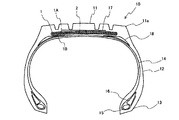
図1は、本発明のタイヤの一例のトラック・バス用タイヤを示すタイヤ幅方向断面図である。図示するタイヤ10は、接地部を形成するトレッド部11と、このトレッド部11の両側部に連続してタイヤ半径方向内方へ延びる一対のサイドウォール部12と、各サイドウォール部12の内周側に連続するビード部13と、を備えている。トレッド部11、サイドウォール部12およびビード部13は、一方のビード部13から他方のビード部13にわたってトロイド状に延在する一枚のカーカスプライからなるカーカス14により補強されている。また、図示するトラック・バス用タイヤ10においては、一対のビード部13にはそれぞれビードコア15が埋設され、カーカス14は、このビードコア15の周りにタイヤ内側から外側に折り返して係止されている。さらに、ビードコア15のタイヤ半径方向外側には、ビードフィラー16が配置されている。
Hereinafter, the present invention will be described in detail with reference to the drawings.
FIG. 1 is a cross-sectional view in the tire width direction showing a truck / bus tire as an example of the tire of the present invention. The illustrated
また、本発明のタイヤは、カーカス14のクラウン部タイヤ半径方向外側に、補強コードを螺旋状に巻回して上層1Aと下層1Bとを形成してなる構造を有する螺旋状コード層1を備えている。また、図1に示す例では、螺旋状コード層1の上層1Aと下層1Bとの間に、芯材コード層2が配置されている。
Further, the tire of the present invention includes a
本発明においては、螺旋状コード層1のタイヤ半径方向外側に補助ベルト層17が配置され、この補助ベルト層17のベルトコードのタイヤ周方向に対する角度が30°以上90°以下の範囲である点が重要である。これにより、走行時における補助ベルト層17のベルトコードの角度変化を抑制して、補助ベルト層17のタイヤ幅方向端に生ずる歪を低減することができるので、結果として、螺旋状コード層と補助ベルト層との間でのセパレーションの発生を抑制することができる。
In the present invention, the
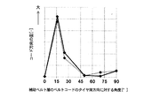
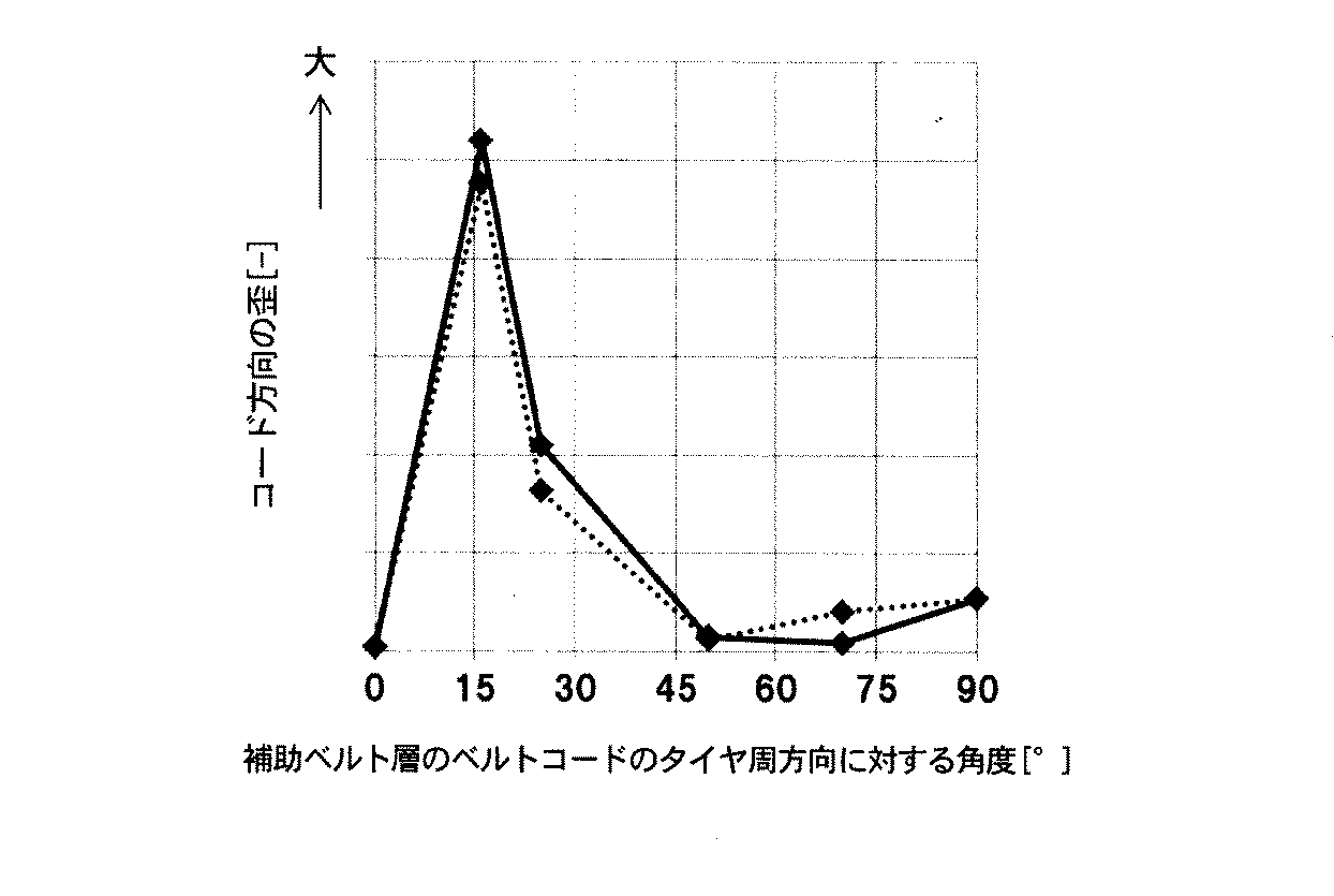
図4に、補助ベルト層17のベルトコードのタイヤ周方向に対する角度と、補助ベルト層17のタイヤ幅方向端におけるコード方向の歪との関係を示すグラフを示す。実線は補助ベルト層17のベルトコードのタイヤ周方向に対する傾斜方向が、螺旋状コード層1の上層1Aと同方向である場合を示し、点線は補助ベルト層17のベルトコードのタイヤ周方向に対する傾斜方向が、螺旋状コード層1の上層1Aと逆方向である場合を示す。図示するように、補助ベルト層17のタイヤ幅方向端におけるコード方向の歪は、補助ベルト17のベルトコードのタイヤ周方向に対する角度が0°〜30°程度の範囲、すなわち、補助ベルト17のベルトコードの方向がタイヤ周方向に近い場合に顕著に高くなっている。これは、補助ベルト層17のコード方向がタイヤ周方向に近いと、走行時の繰り返し入力に起因する螺旋状コード層1の上層1Aの補強コードの角度の変化量と補助ベルト層17のベルトコードの角度の変化量とに差が生じて、補助ベルト層17の幅方向端部のゴムに歪が集中するためと考えられる。これに対し、本発明においては、補助ベルト層17のベルトコードのタイヤ周方向に対する角度を30°以上90°以下の範囲としたことで、走行時にタイヤ周方向に応力がかかっても、補助ベルト層17のベルトコードの角度が螺旋状コード層1の補強コードの角度変化とともに変化するので、補助ベルト層17の幅方向端部のゴムに歪が生じ難くなって、この歪に起因するセパレーションの発生を効果的に抑えることが可能となる。
FIG. 4 shows a graph showing the relationship between the angle of the belt cord of the
本発明においては、補助ベルト層17のベルトコードのタイヤ周方向に対する角度を30°以上90°以下の範囲とするものであれば、補助ベルト17の幅方向端部におけるセパレーション発生の抑制効果を得ることができるが、さらに、螺旋状コード層1の補強コードおよび芯材コード層2の芯材コードのうち少なくともいずれか一方の、タイヤ周方向に対する角度を30°未満、特には12°以上30°未満とすることが好ましい。これにより、タイヤ周方向に近いこれらコードのうちのいずれかに張力を負担させることができるので、補助ベルト層17にかかる張力を低減して、セパレーションの抑制効果をより向上することができる。
In the present invention, if the angle of the belt cord of the
ここで、図4から、補助ベルト層17のベルトコードのタイヤ周方向に対する角度を45°以上90°以下の範囲として、タイヤ幅方向により近い範囲とする場合には、補助ベルト層17の幅方向端部における歪量はかなり低くなるので、螺旋状コード層1および芯材コード層2のコード角度はあまり問題にならないと考えられる。これに対し、補助ベルト層17のベルトコードのタイヤ周方向に対する角度が30°以上45°未満の範囲である場合には、上記のように、螺旋状コード層1の補強コードおよび芯材コード層2の芯材コードのうち少なくともいずれか一方の、タイヤ周方向に対する角度を30°未満とすることが、セパレーションの抑制効果をより良好に得ることができるために、好ましい。
Here, from FIG. 4, when the angle of the belt cord of the
本発明のタイヤにおいては、螺旋状コード層1のタイヤ半径方向外側に設ける補助ベルト層17について、上記ベルトコード角度の条件を満足する点のみが重要であり、これにより本発明の所期の効果を得ることができる。それ以外の構成については特に制限はなく、常法に従い適宜構成することが可能である。本発明においては、補助ベルト層に相当する層を2層以上設ける場合には、螺旋状コード層のタイヤ半径方向外側に隣り合って配設された補助ベルト層のみが上記ベルトコード角度の条件を満足するものであれば、本発明の所期の効果を得ることができる。
In the tire of the present invention, it is important that the
本発明において、螺旋状コード層1は、補強コードを1本または複数本、例えば、2〜100本で並列に引き揃えて、ゴムにより被覆してなるゴム−コード複合体を、螺旋状に巻回して平坦な帯状体とするか、または、芯材コード層2の周囲に螺旋状に巻き付けることにより形成される。螺旋状コード層1における補強コードの打ち込み数は、例えば、5〜60本/50mmの範囲が好ましい。
In the present invention, the
また、本発明において、螺旋状コード層1の補強コードの角度は、タイヤ周方向に対し12°〜90°の範囲であることが好ましい。螺旋状コード層1は、タイヤ幅方向端部において上層1Aと下層1Bとが切り離されていないので、タイヤの内圧負荷時に張力を発揮し、径成長しにくいという特性を有し、その結果、螺旋状コード層1を設けるとクラウン部が丸くなる傾向にあるが、螺旋状コード層1の補強コードの角度を12°以上とすることで、内圧負荷時における径成長を許容範囲内とすることができ、ショルダー部における摩耗の発生を抑制することができる。なお、本発明において、螺旋状コード層1の補強コードの角度は、タイヤ赤道面上で測定した値を用いることができる。この角度は、好適には12°〜45°の範囲である。なお、前述したように、芯材コード層2の芯材コードの角度を30°未満としない場合には、螺旋状コード層1の補強コードの角度は、タイヤ周方向に対し30°未満の範囲とすることが好ましい。
Further, in the present invention, the angle of the reinforcing cord of the
図示する例では、螺旋状コード層1は、上層1Aと下層1Bとの間に芯材コード層2を備え、すなわち、芯材コード層2に対し補強コードが螺旋状に巻き付けられて螺旋状コード層1が形成されているが、本発明においては、これに制限されず、芯材コード層2は設けなくてもよい。芯材コード層2を備えると、タイヤ周方向の剛性が高くなってタガ効果が向上する半面、上述した螺旋状コード層1のタイヤ幅方向端部における補強コードのタイヤ周方向の張力が高まりやすくなる。芯材コード層2を設ける場合、芯材コード層2は1層で設けてもよく、複数層、例えば、2〜10層で積層して設けることもできる。ここで、芯材コード層2は、芯材コードを多数本並行に引き揃え、この上下に未加硫ゴムを配置して、芯材コードをゴム被覆することにより製造される。芯材コード層2における芯材コードの打ち込み数は、例えば、5〜60本/50mmの範囲が好ましい。
In the illustrated example, the
本発明において、芯材コード層2の芯材コードのタイヤ周方向に対する角度は、40°〜90°の範囲であるものとすることができる。芯材コードの角度を上記範囲とすることで、芯材コードの張力が低下して、芯材コードの破断に至るまでの余剰が多くなる。その結果、障害物の入力を受けても芯材コードは破断しにくくなる。このような効果を良好に得るためには、芯材コード層2の芯材コードの傾斜角度は、50°〜90°であることがより好ましい。一方で、芯材コード層2の芯材コードのタイヤ周方向に対する角度が、上記の通りタイヤ幅方向に近くなると、前述した螺旋状コード層1のタイヤ幅方向端部における補強コードの張力の上昇の課題が顕著となるので、特に本発明の適用が有用といえる。なお、芯材コード層2を複数層設ける場合には、複数層の芯材コード層2が交錯ベルト層を構成してもよい。なお、前述したように、螺旋状コード層1の補強コードの角度を30°未満としない場合には、芯材コード層2の芯材コードの角度は、タイヤ周方向に対し30°未満の範囲とすることが好ましい。
In the present invention, the angle of the core
本発明において、螺旋状コード層1の補強コードおよび芯材コード層2の芯材コードの材質としては、特に制限はなく、従来汎用の各種の金属コードや有機繊維コードなどを適宜用いることができる。具体的には例えば、金属コードとしては、スチールフィラメントや、スチールフィラメントを複数本撚り合わせたスチールコードを用いることができる。この場合、コードの撚り構造についても種々の設計が可能であり、断面構造、撚りピッチ、撚り方向、隣接するフィラメント同士の距離も様々なものが使用できる。断面構造としては、単撚り、層撚り、複撚りなど様々な撚り構造を採用することができ、また、断面形状が偏平のコードを使用することもできる。なお、スチールコードを構成するスチールフィラメントは、鉄を主成分とし、炭素、マンガン、ケイ素、リン、硫黄、銅、クロムなど種々の微量成分を含んでいてもよい。また、スチールフィラメントの表面には、ゴムとの接着性を改善するため、ブラスめっきが施されていてもよい。
In the present invention, the material of the reinforcing cord of the
有機繊維としては、アラミド繊維(芳香族ポリアミド繊維)、ポリケトン(PK)繊維、ポリパラフェニレンベンゾビスオキサゾール(PBO)繊維、ポリアリレート繊維等を用いることができる。また、ポリアクリロニトリル(PAN)系炭素繊維やピッチ系炭素繊維、レーヨン系炭素繊維等の炭素繊維(カーボンファイバー)、ガラス繊維(グラスファイバー)、玄武岩繊維や安山岩繊維等の岩石繊維(ロックウール)などを用いることもできる。なお、これらの補強コードには、接着剤処理を施してゴムとの接着性を向上させることが好ましい。この接着剤処理は、RFL系接着剤等の汎用の接着剤を用いて、常法に従って行うことができる。さらに、上記のうちのいずれか2種以上からなるハイブリッドコードを用いてもよい。 As the organic fiber, aramid fiber (aromatic polyamide fiber), polyketone (PK) fiber, polyparaphenylene benzobisoxazole (PBO) fiber, polyallylate fiber and the like can be used. In addition, polyacrylonitrile (PAN) -based carbon fiber, pitch-based carbon fiber, carbon fiber (carbon fiber) such as rayon-based carbon fiber, glass fiber (glass fiber), rock fiber (rock wool) such as genbu rock fiber and anshan rock fiber, etc. Can also be used. It is preferable that these reinforcing cords are subjected to an adhesive treatment to improve the adhesiveness with rubber. This adhesive treatment can be carried out according to a conventional method using a general-purpose adhesive such as an RFL adhesive. Further, a hybrid code composed of any two or more of the above may be used.
本発明において、螺旋状コード層1や芯材コード層2のコーティングゴムに用いるゴム組成物としては、既知のものを用いることができ、特に制限されない。例えば、コーティングゴムに用いられるゴム組成物のゴム成分としては、天然ゴムの他;ビニル芳香族炭化水素/共役ジエン共重合体、ポリイソプレンゴム、ブタジエンゴム、ブチルゴム、ハロゲン化ブチルゴム、エチレン−プロピレンゴム等の合成ゴム等の公知のゴム成分の全てを用いることができる。ゴム成分は1種単独で用いても、2種以上を併用してもよい。金属コードとの接着特性およびゴム組成物の破壊特性の観点からは、ゴム成分としては、天然ゴムおよびポリイソプレンゴムの少なくとも一方よりなるか、50質量%以上の天然ゴムを含み残部が合成ゴムからなるものが好ましい。
In the present invention, as the rubber composition used for the coating rubber of the
本発明において、コーティングゴムに用いられるゴム組成物には、カーボンブラックやシリカ等の充填剤、アロマオイル等の軟化剤、ヘキサメチレンテトラミン、ペンタメトキシメチルメラミン、ヘキサメチレンメチルメラミン等のメトキシメチル化メラミン等のメチレン供与体、加硫促進剤、加硫促進助剤、老化防止剤等のゴム業界で通常使用される配合剤を通常の配合量で適宜配合することができる。また、本発明においてコーティングゴムとして用いられるゴム組成物の調製方法に特に制限はなく、常法に従い、例えば、バンバリーミキサーやロール等を用いて、ゴム成分に、硫黄、有機酸コバルト塩および各種配合剤等を練り込んで調製すればよい。 In the present invention, the rubber composition used for the coated rubber includes fillers such as carbon black and silica, softeners such as aroma oil, and methoxymethylated melamines such as hexamethylenetetramine, pentamethoxymethylmelamine and hexamethylenemethylmelamine. Methylene donors such as, vulcanization accelerators, vulcanization accelerator aids, antiaging agents, and other compounding agents usually used in the rubber industry can be appropriately compounded in ordinary compounding amounts. Further, the method for preparing the rubber composition used as the coating rubber in the present invention is not particularly limited, and sulfur, an organic acid cobalt salt and various blends are added to the rubber component by using, for example, a Banbury mixer or a roll according to a conventional method. It may be prepared by kneading an agent or the like.
また、図示するトラック・バス用タイヤ10において、補助ベルト層17は、ベルトコードがタイヤ周方向に対し所定の角度をなす傾斜ベルトとすることができ、ベルトコードを多数本引き揃えて、ゴムにより被覆することによって形成される。傾斜ベルト層の補強コードとしては、例えば、金属コード、特にスチールコードを用いるのが最も一般的であるが、有機繊維コードを用いてもよい。スチールコードは鉄を主成分とし、炭素、マンガン、ケイ素、リン、硫黄、銅、クロムなど種々の微量含有物を含むスチールフィラメントからなるものを用いることができる。
Further, in the illustrated truck /
スチールコードとしては、複数のフィラメントを撚り合せたコード以外にも、スチールモノフィラメントコードを用いてもよい。なお、スチールコードの撚り構造も種々の設計が可能であり、断面構造、撚りピッチ、撚り方向、隣接するスチールコード同士の距離も様々なものが使用できる。また、異なる材質のフィラメントを撚り合せたコードを採用することもでき、断面構造としても特に限定されず、単撚り、層撚り、複撚りなど様々な撚り構造を取ることができる。また、補助ベルト層17の幅は、トレッド幅の40%〜115%とすることが好ましく、特に50%〜70%が好ましい。なお、螺旋状コード層1の端部のタイヤ径方向内側には、ベルトアンダークッションゴム18を設けることが好ましい。これにより、螺旋状コード層1の端部の歪・温度を低減して、タイヤ耐久性を向上させることができる。
As the steel cord, a steel monofilament cord may be used in addition to the cord obtained by twisting a plurality of filaments. Various designs of the twisted structure of the steel cords are possible, and various ones can be used with various cross-sectional structures, twisting pitches, twisting directions, and distances between adjacent steel cords. Further, a cord obtained by twisting filaments of different materials can be adopted, and the cross-sectional structure is not particularly limited, and various twisted structures such as single twist, layer twist, and double twist can be adopted. The width of the
本発明のトラック・バス用タイヤ10においては、カーカス14は従来構造を含めて種々の構成を採用することができ、ラジアル構造、バイアス構造のいずれであってもよい。カーカス14としては、スチールコード層からなるカーカスプライを1〜2層とすることが好ましい。また、例えば、タイヤ径方向におけるカーカス最大幅位置は、ビード部13側に近づけてもよく、トレッド部11側に近づけてもよい。例えば、カーカス14の最大幅位置は、ビードベース部からタイヤ径方向外側に、タイヤ高さ対比で50%〜90%の範囲に設けることができる。また、カーカス14は、図示するように、一対のビードコア15間を途切れずに延びる構造が一般的であり好ましいが、ビードコア15から延びてトレッド部11付近で途切れるカーカス片を一対用いて形成することもできる。
In the truck /
また、カーカス14の折り返し部は、さまざまな構造を採用することができる。例えば、カーカス14の折り返し端をビードフィラー16の上端よりもタイヤ径方向内側に位置させることができ、また、カーカス折り返し端をビードフィラー16の上端やタイヤ最大幅位置よりもタイヤ径方向外側まで延ばしてもよく、この場合、螺旋状コード層1のタイヤ幅方向端よりもタイヤ幅方向内側まで延ばすこともできる。さらに、カーカスプライが複数層の場合には、カーカス14の折り返し端のタイヤ径方向位置を異ならせることもできる。また、カーカス14の折り返し部を存在させずに、複数のビードコア部材で挟み込んだ構造としてもよく、ビードコア15に巻きつけた構造を採用することもできる。なお、カーカス14の打ち込み数としては、一般的には5〜60本/50mmの範囲であるが、これに限定されるものではない。
Further, various structures can be adopted for the folded portion of the
また、本発明のトラック・バス用タイヤ10においては、螺旋状コード層1および補助ベルト層17のタイヤ径方向外側に、周方向コード層(図示せず)を設けてもよい。
Further, in the truck /
本発明のトラック・バス用タイヤ10においては、サイドウォール部12の構成についても既知の構造を採用することができる。例えば、タイヤ最大幅位置は、ビードベース部からタイヤ径方向外側に、タイヤ高さ対比で50%〜90%の範囲に設けることができる。本発明のトラック・バス用タイヤ10においては、乗用車用タイヤとは異なり、リムフランジと接触する凹部が形成されずに、タイヤ幅方向に凸となる滑らかな曲線として形成されていることが好ましい。
In the truck /
また、ビードコア15は、円形や多角形状など、さまざまな構造を採用することができる。なお、上述のとおり、ビード部13としては、カーカス14をビードコア15に巻きつける構造のほか、カーカス14を複数のビードコア部材で挟みこむ構造としてもよい。図示するトラック・バス用タイヤ10においては、ビードコア15のタイヤ半径方向外側にビードフィラー16が配置されているが、このビードフィラー16は、タイヤ径方向に分かれた複数のゴム部材から構成されていてもよい。
Further, the
本発明のトラック・バス用タイヤ10においては、トレッドパターンとしては、リブ状陸部主体のパターン、ブロックパターン、非対称パターンでもよく、回転方向指定であってもよい。
In the truck /
リブ状陸部主体パターンは、一本以上の周方向溝もしくは周方向溝とトレッド端部によりタイヤ幅方向を区画された、リブ状陸部を主体とするパターンである。ここでリブ状陸部とはタイヤ幅方向に横断する横溝を有さずにタイヤ周方向に延びる陸部をいうが、リブ状陸部はサイプやリブ状陸部内で終端する横溝を有していてもよい。ラジアルタイヤは特に高内圧使用下において高接地圧となるため、周方向剪断剛性を増加させることによりウェット路面上での接地性が向上するためと考えられる。リブ状陸部を主体とするパターンの例としては、赤道面を中心とするトレッド幅の80%の領域においてリブ状陸部のみからなるトレッドパターン、すなわち、横溝を有さないパターンとすることができる。このようなパターンは、この領域における排水性能が特にウェット性能への寄与が大きい。 The rib-shaped land portion main pattern is a pattern mainly composed of a rib-shaped land portion in which the tire width direction is divided by one or more circumferential grooves or circumferential grooves and a tread end portion. Here, the rib-shaped land portion refers to a land portion that extends in the tire circumferential direction without having a lateral groove that crosses in the tire width direction, but the rib-shaped land portion has a lateral groove that terminates in a sipe or a rib-shaped land portion. You may. Since radial tires have a high ground pressure especially when using high internal pressure, it is considered that increasing the shear rigidity in the circumferential direction improves the ground contact on a wet road surface. As an example of a pattern mainly composed of a rib-shaped land portion, a tread pattern consisting of only a rib-shaped land portion in a region of 80% of the tread width centered on the equatorial plane, that is, a pattern having no lateral groove can be used. it can. In such a pattern, the drainage performance in this region greatly contributes to the wet performance.
ブロックパターンは、周方向溝と幅方向溝によって区画されたブロック陸部を有するパターンであり、ブロックパターンのタイヤは、基本的な氷上性能および雪上性能に優れている。 The block pattern is a pattern having a block land portion partitioned by a circumferential groove and a width direction groove, and the tire of the block pattern is excellent in basic ice performance and snow performance.
非対称パターンは、赤道面を境として左右のトレッドパターンが非対称のパターンである。例えば、装着方向指定のタイヤの場合には、赤道面を境とした車両装着方向内側と車両装着方向外側のタイヤ半部においてネガティブ率に差を設けたものでもよく、赤道面を境とした車両装着方向内側と車両装着方向外側のタイヤ半部において、周方向溝の数が異なる構成のものであってもよい。 The asymmetric pattern is a pattern in which the left and right tread patterns are asymmetric with respect to the equatorial plane. For example, in the case of a tire with a designated mounting direction, a difference in negative ratio may be provided between the inner half of the tire in the vehicle mounting direction and the outer side in the vehicle mounting direction with the equatorial plane as the boundary, and the vehicle with the equatorial plane as the boundary. The tire halves on the inner side in the mounting direction and the outer side in the vehicle mounting direction may have different numbers of circumferential grooves.
トレッドゴムとしては、特に制限はなく、従来から用いられているゴムを用いることができる。また、トレッドゴムはタイヤ径方向に異なる複数のゴム層で形成されていてもよく、例えば、いわゆるキャップ・ベース構造であってもよい。複数のゴム層としては正接損失、モジュラス、硬度、ガラス転移温度、材質等が異なっているものを使用することができる。また、複数のゴム層のタイヤ径方向の厚みの比率は、タイヤ幅方向に変化していてもよく、また周方向溝底のみ等をその周辺と異なるゴム層とすることもできる。 The tread rubber is not particularly limited, and conventionally used rubber can be used. Further, the tread rubber may be formed of a plurality of rubber layers different in the tire radial direction, and may have a so-called cap base structure, for example. As the plurality of rubber layers, those having different tangent loss, modulus, hardness, glass transition temperature, material, and the like can be used. Further, the ratio of the thicknesses of the plurality of rubber layers in the tire radial direction may change in the tire width direction, and only the circumferential groove bottom or the like may be a rubber layer different from the periphery thereof.
さらに、トレッドゴムはタイヤ幅方向に異なる複数のゴム層で形成されていてもよく、いわゆる、分割トレッド構造でもよい。上記の複数のゴム層としては正接損失、モジュラス、硬度、ガラス転移温度、材質等が異なっているものを使用することができる。また、複数のゴム層のタイヤ幅方向の長さの比率は、タイヤ径方向に変化していてもよく、また周方向溝近傍のみ、トレッド端近傍のみ、ショルダー陸部のみ、センター陸部のみといった限定された一部の領域のみをその周囲とは異なるゴム層とすることもできる。また、トレッド部は、タイヤ幅方向の端部に角部11aが形成されていることが好ましい。
Further, the tread rubber may be formed of a plurality of rubber layers different in the tire width direction, and may have a so-called split tread structure. As the above-mentioned plurality of rubber layers, those having different tangent loss, modulus, hardness, glass transition temperature, material, and the like can be used. Further, the ratio of the lengths of the plurality of rubber layers in the tire width direction may change in the tire radial direction, such as only in the vicinity of the circumferential groove, only in the vicinity of the tread end, only in the shoulder land portion, and only in the center land portion. It is also possible to make only a limited part of the area a rubber layer different from the surrounding area. Further, it is preferable that the tread portion has a
図1に示すタイヤはトラック・バス用タイヤであるが、本発明は、これに限られず、乗用車用、建設車両用、二輪車用、航空機用、農業用のタイヤ等にも好適に適用することができる。また、タイヤとしては、空気入りタイヤ以外に限定されず、ソリッドタイヤや非空気入りタイヤにも適用することができる。 The tire shown in FIG. 1 is a tire for trucks and buses, but the present invention is not limited to this, and the present invention may be suitably applied to tires for passenger cars, construction vehicles, motorcycles, aircraft, agriculture, and the like. it can. Further, the tire is not limited to the pneumatic tire, and can be applied to a solid tire and a non-pneumatic tire.
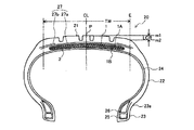
図2は、本発明の乗用車用タイヤの一構成例を示すタイヤ幅方向断面図である。図示する乗用車用タイヤ20は、接地部を形成するトレッド部21と、このトレッド部21の両側部に連続してタイヤ半径方向内方へ延びる一対のサイドウォール部22と、各サイドウォール部22の内周側に連続するビード部23と、を備えている。トレッド部21、サイドウォール部22およびビード部23は、一方のビード部23から他方のビード部23にわたってトロイド状に延びる一枚のカーカスプライからなるカーカス24により補強されている。また、図示する乗用車用タイヤ20においては、一対のビード部23にはそれぞれビードコア25が埋設され、カーカス24は、このビードコア25の周りにタイヤ内側から外側に折り返して係止されている。さらに、ビードコア25のタイヤ半径方向外側には、ビードフィラー26が配置されている。
FIG. 2 is a cross-sectional view in the tire width direction showing a configuration example of a passenger car tire of the present invention. The illustrated
図示する乗用車用タイヤ20においては、カーカス24のクラウン部タイヤ径方向外側に、補強コードを螺旋状に巻回して上層1Aと下層1Bとを形成してなる構造を有する螺旋状コード層1と、補助ベルト層27とが、順次配設されている。
In the illustrated
本発明においては、補助ベルト層27のベルトコードのタイヤ周方向に対する角度が上記条件を満足することが重要であり、これにより、本発明の所期の効果を得ることができる。ここで、図2に示す乗用車用タイヤの場合、補助ベルト層27としては、螺旋状コード層1の全幅以上にわたって配置されるキャップ層27a、または、螺旋状コード層1の両端部を覆う領域に配置されるレイヤー層27bが挙げられる。キャップ層27aおよびレイヤー層27bは、通常、多数本のコードを引き揃えてゴムにより被覆してなる一定幅のストリップを、螺旋状に巻回することにより形成される。キャップ層27aおよびレイヤー層27bはそれぞれ単独で設けてもよく、併用してもよい。または、2層以上のキャップ層や2層以上のレイヤー層の組み合わせであってもよい。
In the present invention, it is important that the angle of the belt cord of the
キャップ層27aおよびレイヤー層27bの補強コードとしては、種々の材質が採用可能であり、代表的な例としては、レーヨン、ナイロン、ポリエチレンナフタレート(PEN)、ポリエチレンテレフタレート(PET)、アラミド、ガラス繊維、炭素繊維、スチール等が挙げられる。軽量化の点から、有機繊維コードが特に好ましい。補強コードはモノフィラメントコードや、複数のフィラメントを撚り合せたコード、さらには異なる材質のフィラメントを撚り合せたハイブリットコードを採用することもできる。また、補強コードには、破断強度を高めるために波状のコードを用いてもよい。同様に破断強度を高めるために、例えば、破断時の伸びが4.5〜5.5%のハイエロンゲーションコードを用いてもよい。
Various materials can be used as the reinforcing cords for the
キャップ層27aおよびレイヤー層27bの打ち込み数は、一般的には20〜60本/50mmの範囲であるが、この範囲に限定されるものではない。また、キャップ層27aにおいては、タイヤ幅方向に剛性・材質・層数・打ち込み密度等の分布を持たせることもでき、例えばタイヤ幅方向端部のみ層数を増やすこともでき、一方でセンター部のみ層数を増やすこともできる。
The number of the
キャップ層27aおよびレイヤー層27bは、スパイラル層として構成することが製造の観点から特に有利である。この場合、平面内において互いに平行に配列された複数本のコアワイヤを、上記平行配列を維持したままラッピングワイヤによって束ねた、ストリップ状のコードによって形成してもよい。
It is particularly advantageous from the viewpoint of manufacturing that the
本発明の乗用車用タイヤ20においては、カーカス24は従来構造を含めて種々の構成を採用することができ、ラジアル構造、バイアス構造のいずれであってもよい。カーカス24としては、有機繊維コード層からなるカーカスプライを1〜2層とすることが好ましい。また、タイヤ径方向におけるカーカス24の最大幅位置は、例えば、ビード部23側に近づけてもよく、トレッド部21側に近づけてもよい。例えば、カーカス24の最大幅位置は、ビードベース部からタイヤ径方向外側に、タイヤ高さ対比で50%〜90%の範囲に設けることができる。また、カーカス24は、図示するように、一対のビードコア25間を途切れずに延びる構造が一般的であり好ましいが、ビードコア25から延びてトレッド部21付近で途切れるカーカスプライ片を一対用いて形成することもできる(図示せず)。
In the
また、カーカス24の折り返し部は、さまざまな構造を採用することができる。例えば、カーカス24の折り返し端をビードフィラー26の上端よりもタイヤ径方向内側に位置させることができ、また、カーカス24の折り返し端をビードフィラー26の上端やタイヤ最大幅位置よりもタイヤ径方向外側まで延ばしてもよく、この場合、螺旋状コード層1のタイヤ幅方向端よりもタイヤ幅方向内側まで伸ばすこともできる。さらに、カーカスプライが複数層の場合には、カーカス24の折り返し端のタイヤ径方向位置を異ならせることもできる。また、カーカス24の折り返し部を存在させずに、複数のビードコア部材で挟み込んだ構造としてもよく、ビードコア25に巻きつけた構造を採用することもできる。なお、カーカス24の打ち込み数としては、一般的には5〜60本/50mmの範囲であるが、これに限定されるものではない。
Further, various structures can be adopted for the folded portion of the
本発明の乗用車用タイヤ20において、トレッド部21の形状としては、狭幅大径サイズの乗用車用タイヤの場合には、タイヤ幅方向断面にて、タイヤ赤道面CLにおけるトレッド表面上の点Pを通りタイヤ幅方向に平行な直線をm1とし、接地端Eを通りタイヤ幅方向に平行な直線をm2として、直線m1と直線m2とのタイヤ径方向の距離を落ち高LCRとし、タイヤのトレッド幅をTWとするとき、比LCR/TWを0.045以下とすることが好ましい。比LCR/TWを上記の範囲とすることにより、タイヤのクラウン部がフラット化(平坦化)し、接地面積が増大して、路面からの入力(圧力)を緩和して、タイヤ径方向の撓み率を低減し、タイヤの耐久性および耐摩耗性を向上させることができる。また、トレッド端部がなめらかであることが好ましい。
In the
また、トレッドパターンとしては、フルラグパターン、リブ状陸部主体のパターン、ブロックパターン、非対称パターンでもよく、回転方向指定であってもよい。 Further, the tread pattern may be a full lug pattern, a rib-shaped land-based pattern, a block pattern, an asymmetric pattern, or a rotation direction designation.
フルラグパターンとしては、赤道面近傍から接地端までタイヤ幅方向に延びる幅方向溝を有するパターンとしてもよく、この場合に周方向溝を含まなくてもよい。このような横溝が主体のパターンは、特に雪上性能を効果的に発揮することができる。 The full lug pattern may be a pattern having a width direction groove extending in the tire width direction from the vicinity of the equatorial plane to the ground contact end, and in this case, the circumferential groove may not be included. Such a pattern mainly composed of lateral grooves can effectively exhibit performance on snow.
リブ状陸部主体パターンは、一本以上の周方向溝もしくは周方向溝とトレッド端部によりタイヤ幅方向を区画された、リブ状陸部を主体とするパターンである。ここでリブ状陸部とはタイヤ幅方向に横断する横溝を有さずにタイヤ周方向に延びる陸部をいうが、リブ状陸部はサイプやリブ状陸部内で終端する横溝を有していてもよい。ラジアルタイヤは特に高内圧使用下において高接地圧となるため、周方向剪断剛性を増加させることによりウェット路面上での接地性が向上するためと考えられる。リブ状陸部を主体とするパターンの例としては、赤道面を中心とするトレッド幅の80%の領域においてリブ状陸部のみからなるトレッドパターン、すなわち、横溝を有さないパターンとすることができる。このようなパターンは、この領域における排水性能が特にウェット性能への寄与が大きい。 The rib-shaped land portion main pattern is a pattern mainly composed of a rib-shaped land portion in which the tire width direction is divided by one or more circumferential grooves or circumferential grooves and a tread end portion. Here, the rib-shaped land portion refers to a land portion that extends in the tire circumferential direction without having a lateral groove that crosses in the tire width direction, but the rib-shaped land portion has a lateral groove that terminates in a sipe or a rib-shaped land portion. You may. Since radial tires have a high ground pressure especially when using high internal pressure, it is considered that increasing the shear rigidity in the circumferential direction improves the ground contact on a wet road surface. As an example of a pattern mainly composed of a rib-shaped land portion, a tread pattern consisting of only a rib-shaped land portion in a region of 80% of the tread width centered on the equatorial plane, that is, a pattern having no lateral groove can be used. it can. In such a pattern, the drainage performance in this region greatly contributes to the wet performance.
ブロックパターンは、周方向溝と幅方向溝によって区画されたブロック陸部を有するパターンであり、ブロックパターンのタイヤは、基本的な氷上性能および雪上性能に優れている。 The block pattern is a pattern having a block land portion partitioned by a circumferential groove and a width direction groove, and the tire of the block pattern is excellent in basic ice performance and snow performance.
非対称パターンは、赤道面を境として左右のトレッドパターンが非対称のパターンである。例えば、装着方向指定のタイヤの場合には、赤道面を境とした車両装着方向内側と車両装着方向外側のタイヤ半部においてネガティブ率に差を設けたものでもよく、赤道面を境とした車両装着方向内側と車両装着方向外側のタイヤ半部において、周方向溝の数が異なる構成のものであってもよい。 The asymmetric pattern is a pattern in which the left and right tread patterns are asymmetric with respect to the equatorial plane. For example, in the case of a tire with a designated mounting direction, a difference in negative ratio may be provided between the inner half of the tire in the vehicle mounting direction and the outer side in the vehicle mounting direction with the equatorial plane as the boundary, and the vehicle with the equatorial plane as the boundary. The tire halves on the inner side in the mounting direction and the outer side in the vehicle mounting direction may have different numbers of circumferential grooves.
トレッドゴムとしては、特に制限はなく、従来から用いられているゴムを用いることができ、発泡ゴムを用いてもよい。また、トレッドゴムはタイヤ径方向に異なる複数のゴム層で形成されていてもよく、例えば、いわゆるキャップ・ベース構造であってもよい。複数のゴム層としては正接損失、モジュラス、硬度、ガラス転移温度、材質等が異なっているものを使用することができる。また、複数のゴム層のタイヤ径方向の厚みの比率は、タイヤ幅方向に変化していてもよく、また周方向溝底のみ等をその周辺と異なるゴム層とすることもできる。 The tread rubber is not particularly limited, and conventionally used rubber can be used, and foam rubber may be used. Further, the tread rubber may be formed of a plurality of rubber layers different in the tire radial direction, and may have a so-called cap base structure, for example. As the plurality of rubber layers, those having different tangent loss, modulus, hardness, glass transition temperature, material, and the like can be used. Further, the ratio of the thicknesses of the plurality of rubber layers in the tire radial direction may change in the tire width direction, and only the circumferential groove bottom or the like may be a rubber layer different from the periphery thereof.
さらに、トレッドゴムはタイヤ幅方向に異なる複数のゴム層で形成されていてもよく、いわゆる、分割トレッド構造でもよい。上記の複数のゴム層としては正接損失、モジュラス、硬度、ガラス転移温度、材質等が異なっているものを使用することができる。また、複数のゴム層のタイヤ幅方向の長さの比率は、タイヤ径方向に変化していてもよく、また周方向溝近傍のみ、トレッド端近傍のみ、ショルダー陸部のみ、センター陸部のみといった限定された一部の領域のみをその周囲とは異なるゴム層とすることもできる。 Further, the tread rubber may be formed of a plurality of rubber layers different in the tire width direction, and may have a so-called split tread structure. As the above-mentioned plurality of rubber layers, those having different tangent loss, modulus, hardness, glass transition temperature, material, and the like can be used. Further, the ratio of the lengths of the plurality of rubber layers in the tire width direction may change in the tire radial direction, such as only in the vicinity of the circumferential groove, only in the vicinity of the tread end, only in the shoulder land portion, and only in the center land portion. It is also possible to make only a limited part of the area a rubber layer different from the surrounding area.
本発明の乗用車用タイヤ20においては、サイドウォール部22の構成についても既知の構造を採用することができる。例えば、タイヤ最大幅位置は、ビードベース部からタイヤ径方向外側に、タイヤ高さ対比で50%〜90%の範囲に設けることができる。また、リムガードを有する構造としてもよい。本発明の乗用車用タイヤ20においては、リムフランジと接触する凹部23aが形成されていることが好ましい。
In the
また、ビードコア25は、円形や多角形状など、さまざまな構造を採用することができる。なお、上述のとおり、ビード部23としては、カーカス24をビードコア25に巻きつける構造のほか、カーカス24を複数のビードコア部材で挟みこむ構造としてもよい。図示する乗用車用タイヤ20においては、ビードコア25のタイヤ半径方向外側に、ビードフィラー26が配置されているが、本発明の乗用車用タイヤ20においては、ビードフィラー26は設けなくてもよい。
Further, the
本発明の乗用車用タイヤは、図示はしないが、タイヤの最内層には通常インナーライナーが配置されていてもよい。インナーライナーは、ブチルゴムを主体としたゴム層のほか、樹脂を主成分とするフィルム層によって形成することができる。また、図示はしないが、タイヤ内面には、空洞共鳴音を低減するために、多孔質部材を配置したり、静電植毛加工を行うこともできる。さらに、タイヤ内面には、パンク時の空気の漏れを防ぐためのシーラント部材を備えることもできる。 Although not shown, the passenger car tire of the present invention may have an inner liner usually arranged in the innermost layer of the tire. The inner liner can be formed by a rubber layer mainly composed of butyl rubber or a film layer containing resin as a main component. Further, although not shown, a porous member may be arranged on the inner surface of the tire or electrostatic flocking may be performed in order to reduce the cavity resonance sound. Further, the inner surface of the tire may be provided with a sealant member for preventing air leakage during a puncture.
乗用車用タイヤ20は、特に用途は限定されない。サマー用、オールシーズン用、冬用といった用途のタイヤに適用することができる。また、サイドウォール部22に三日月型の補強ゴム層を有するサイド補強型ランフラットタイヤや、スタッドタイヤといった特殊な構造の乗用車用タイヤに使用することも可能である。
The use of the
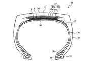
図3は、本発明の建設車両用タイヤの一構成例を示すタイヤ幅方向断面図である。図示する建設車両用タイヤ30においては、接地部を形成するトレッド部31と、このトレッド部31の両側部に連続してタイヤ半径方向内方へ延びる一対のサイドウォール部32と、各サイドウォール部32の内周側に連続するビード部33と、を備えている。トレッド部31、サイドウォール部32およびビード部33は、一方のビード部33から他方のビード部33にわたってトロイド状に延びる一枚のカーカスプライからなるカーカス34により補強されている。また、図示する建設車両タイヤ30においては、一対のビード部33にはそれぞれビードコア35が埋設され、カーカス34は、このビードコア35の周りにタイヤ内側から外側に折り返して係止されている。さらに、ビードコア35のタイヤ半径方向外側には、ビードフィラー36が配置されている。
FIG. 3 is a cross-sectional view in the tire width direction showing a configuration example of the tire for a construction vehicle of the present invention. In the illustrated
図示する建設車両用タイヤ30においては、カーカス34のクラウン領域のタイヤ径方向外側に、補強コードを螺旋状に巻回して上層1Aと下層1Bとを形成してなる構造を有する螺旋状コード層1と、4層のベルト層37a〜37dとが、順次配設されている。建設車両用タイヤ30においては、この4層のベルト層37が、本発明における補助ベルト層に対応する。一般に、建設車両用タイヤは、4層または6層のベルト層からなり、6層のベルト層からなる場合は、第1ベルト層と第2ベルト層とが内側交錯ベルト層群を、第3ベルト層と第4ベルト層とが中間交錯ベルト層群を、第5ベルト層と第6ベルト層とが外側交錯ベルト層群を、それぞれ形成している。本発明の建設車両用タイヤにおいては、内側交錯ベルト層群を螺旋状コード層1で置き換え、中間交錯ベルト層群および外側交錯ベルト層群として補助ベルト層37a〜37dを配置している。また、4層のベルト層からなる建設車両用タイヤの場合は、第1ベルト層および第2ベルト層を螺旋状コード層1と置き換え、第3ベルト層および第4ベルト層を補助ベルト層37a,37bとすればよい。
In the illustrated
なお、6層のベルト層の場合、トレッド幅方向において、螺旋状コード層1の幅は、トレッド踏面の幅の25%以上70%以下、補助ベルト層37a,37bの幅は、トレッド踏面の幅の55%以上90%以下、補助ベルト層37c,37dの幅は、トレッド踏面の幅の60%以上115%以下とすることができる。
In the case of the six belt layers, the width of the
本発明においては、補助ベルト層37のベルトコードのタイヤ周方向に対する角度が上記条件を満足することが重要であり、これにより、本発明の所期の効果を得ることができる。
In the present invention, it is important that the angle of the belt cord of the
本発明の建設車両用タイヤ30において、補助ベルト層37は、補強コードのゴム引き層からなり、タイヤ周方向に対し所定の角度をなす傾斜ベルトとすることができる。傾斜ベルト層の補強コードとしては、例えば、金属コード、特にスチールコードを用いるのが最も一般的であるが、有機繊維コードを用いてもよい。スチールコードは鉄を主成分とし、炭素、マンガン、ケイ素、リン、硫黄、銅、クロムなど種々の微量含有物を含むスチールフィラメントからなるものを用いることができる。
In the
スチールコードとしては、複数のフィラメントを撚り合せたコード以外にも、スチールモノフィラメントコードを用いてもよい。なお、スチールコードの撚り構造も種々の設計が可能であり、断面構造、撚りピッチ、撚り方向、隣接するスチールコード同士の距離も様々なものが使用できる。また、異なる材質のフィラメントを撚り合せたコードを採用することもでき、断面構造としても特に限定されず、単撚り、層撚り、複撚りなど様々な撚り構造を取ることができる。なお、他のベルト層の補強コードの傾斜角度は、タイヤ周方向に対して10°以上とすることが好ましい。また、補助ベルト層37のうち最も幅の大きい最大幅傾斜ベルト層の幅は、トレッド幅の90%〜115%とすることが好ましく、特に100%〜105%が好ましい。なお、補助ベルト層37端部のタイヤ径方向内側には、ベルトアンダークッションゴム39を設けることが好ましい。これにより、補助ベルト層37端部の歪・温度を低減して、タイヤ耐久性を向上させることができる。
As the steel cord, a steel monofilament cord may be used in addition to the cord obtained by twisting a plurality of filaments. Various designs of the twisted structure of the steel cords are possible, and various ones can be used with various cross-sectional structures, twisting pitches, twisting directions, and distances between adjacent steel cords. Further, a cord obtained by twisting filaments of different materials can be adopted, and the cross-sectional structure is not particularly limited, and various twisted structures such as single twist, layer twist, and double twist can be adopted. The inclination angle of the reinforcing cords of the other belt layers is preferably 10 ° or more with respect to the tire circumferential direction. The width of the maximum width inclined belt layer having the largest width among the auxiliary belt layers 37 is preferably 90% to 115% of the tread width, and particularly preferably 100% to 105%. It is preferable to provide the
本発明の建設車両用タイヤにおいては、カーカス34は従来構造を含めて種々の構成を採用することができ、ラジアル構造、バイアス構造のいずれであってもよい。カーカス34としては、スチールコード層からなるカーカスプライを1〜2層とすることが好ましい。また、例えば、タイヤ径方向におけるカーカス最大幅位置は、ビード部33側に近づけてもよく、トレッド部31側に近づけてもよい。例えば、カーカス34の最大幅位置は、ビードベース部からタイヤ径方向外側に、タイヤ高さ対比で50%〜90%の範囲に設けることができる。また、カーカス34は、図示するように、1対のビードコア35間を途切れずに延びる構造が一般的であり好ましいが、ビードコア35から延びてトレッド部31付近で途切れるカーカス片を一対用いて形成することもできる。
In the tire for a construction vehicle of the present invention, the
また、カーカス34の折り返し部は、さまざまな構造を採用することができる。例えば、カーカス34の折り返し端をビードフィラー36の上端よりもタイヤ径方向内側に位置させることができ、また、カーカス34の折り返し端をビードフィラー36の上端やタイヤ最大幅位置よりもタイヤ径方向外側まで伸ばしてもよく、この場合、螺旋状コード層1のタイヤ幅方向端よりもタイヤ幅方向内側まで伸ばすこともできる。さらに、カーカスプライが複数層の場合には、カーカス34の折り返し端のタイヤ径方向位置を異ならせることもできる。また、カーカス34の折り返し部を存在させずに、複数のビードコア部材で挟み込んだ構造としてもよく、ビードコア35に巻きつけた構造を採用することもできる。なお、カーカス34の打ち込み数としては、一般的には10〜60本/50mmの範囲であるが、これに限定されるものではない。
Further, various structures can be adopted for the folded portion of the
本発明の建設車両用タイヤ30においては、サイドウォール部32の構成についても既知の構造を採用することができる。例えば、タイヤ最大幅位置は、ビードベース部からタイヤ径方向外側に、タイヤ高さ対比で50%〜90%の範囲に設けることができる。本発明の建設車両用タイヤ30においては、リムフランジと接触する凹部が形成されていることが好ましい。
In the
また、ビードコア35は、円形や多角形状など、さまざまな構造を採用することができる。なお、上述のとおり、ビード部33としては、カーカス34をビードコア35に巻きつける構造のほか、カーカス34を複数のビードコア部材で挟みこむ構造としてもよい。図示する建設車両用タイヤ30においては、ビードコア35のタイヤ半径方向外側にビードフィラー36が配置されているが、このビードフィラー36は、タイヤ径方向に分かれた複数のゴム部材から構成されていてもよい。
Further, the
本発明の建設車両用タイヤ30においては、トレッドパターンとしては、ラグパターン、ブロックパターン、非対称パターンでもよく、回転方向指定であってもよい。
In the
ラグパターンとしては、赤道面近傍から接地端までタイヤ幅方向に延びる幅方向溝を有するパターンとしてもよく、この場合に周方向溝を含まなくてもよい。 The lug pattern may be a pattern having a width direction groove extending in the tire width direction from the vicinity of the equatorial plane to the ground contact end, and in this case, the circumferential groove may not be included.
ブロックパターンは、周方向溝と幅方向溝によって区画されたブロック陸部を有するパターンである。特に建設車両用タイヤの場合には、耐久性の観点からブロックを大きくすることが好ましく、例えば、ブロックのタイヤ幅方向に測った幅はトレッド幅の25%以上50%以下とすることが好ましい。 The block pattern is a pattern having a block land portion partitioned by a circumferential groove and a width groove. In particular, in the case of tires for construction vehicles, it is preferable to increase the size of the block from the viewpoint of durability. For example, the width of the block measured in the tire width direction is preferably 25% or more and 50% or less of the tread width.
非対称パターンは、赤道面を境として左右のトレッドパターンが非対称のパターンである。例えば、装着方向指定のタイヤの場合には、赤道面を境とした車両装着方向内側と車両装着方向外側のタイヤ半部においてネガティブ率に差を設けたものでもよく、赤道面を境とした車両装着方向内側と車両装着方向外側のタイヤ半部において、周方向溝の数が異なる構成のものであってもよい。 The asymmetric pattern is a pattern in which the left and right tread patterns are asymmetric with respect to the equatorial plane. For example, in the case of a tire with a designated mounting direction, a difference may be provided in the negative ratio between the inner half of the tire in the vehicle mounting direction and the outer side in the vehicle mounting direction with the equatorial plane as the boundary, and the vehicle with the equatorial plane as the boundary. The tire halves on the inner side in the mounting direction and the outer side in the vehicle mounting direction may have different numbers of circumferential grooves.
トレッドゴムとしては、特に制限はなく、従来から用いられているゴムを用いることができる。また、トレッドゴムはタイヤ径方向に異なる複数のゴム層で形成されていてもよく、例えば、いわゆるキャップ・ベース構造であってもよい。複数のゴム層としては正接損失、モジュラス、硬度、ガラス転移温度、材質等が異なっているものを使用することができる。また、複数のゴム層のタイヤ径方向の厚みの比率は、タイヤ幅方向に変化していてもよく、また周方向溝底のみ等をその周辺と異なるゴム層とすることもできる。 The tread rubber is not particularly limited, and conventionally used rubber can be used. Further, the tread rubber may be formed of a plurality of rubber layers different in the tire radial direction, and may have a so-called cap base structure, for example. As the plurality of rubber layers, those having different tangent loss, modulus, hardness, glass transition temperature, material, and the like can be used. Further, the ratio of the thicknesses of the plurality of rubber layers in the tire radial direction may change in the tire width direction, and only the circumferential groove bottom or the like may be a rubber layer different from the periphery thereof.
さらに、トレッドゴムはタイヤ幅方向に異なる複数のゴム層で形成されていてもよく、いわゆる、分割トレッド構造でもよい。上記の複数のゴム層としては正接損失、モジュラス、硬度、ガラス転移温度、材質等が異なっているものを使用することができる。また、複数のゴム層のタイヤ幅方向の長さの比率は、タイヤ径方向に変化していてもよく、また周方向溝近傍のみ、トレッド端近傍のみ、ショルダー陸部のみ、センター陸部のみといった限定された一部の領域のみをその周囲とは異なるゴム層とすることもできる。 Further, the tread rubber may be formed of a plurality of rubber layers different in the tire width direction, and may have a so-called split tread structure. As the above-mentioned plurality of rubber layers, those having different tangent loss, modulus, hardness, glass transition temperature, material, and the like can be used. Further, the ratio of the lengths of the plurality of rubber layers in the tire width direction may change in the tire radial direction, such as only in the vicinity of the circumferential groove, only in the vicinity of the tread end, only in the shoulder land portion, and only in the center land portion. It is also possible to make only a limited part of the area a rubber layer different from the surrounding area.
建設車両においては、トレッド部31のゴムゲージは耐久性の観点から厚い方が好ましく、タイヤ外径の1.5%以上4%以下が好ましく、より好ましくは2%以上3%以下である。また、トレッド部31の接地面に対する溝面積の割合(ネガティブ率)は、20%以下が好ましい。これは、建設車両用タイヤ30は、低速かつ乾燥地域での使用が主体であるため、排水性のためネガティブ率を大きくする必要がないためである。建設車両用タイヤのタイヤサイズとしては、例えばリム径が20インチ以上、特に大型とされるものはリム径が40インチ以上のものである。
In a construction vehicle, the rubber gauge of the
以下、本発明を、実施例を用いてより詳細に説明する。
1層の芯材コード層に対し補強コードを螺旋状に巻き付けて、螺旋状コード層の上層と下層との間に芯材コード層を備える構造の補強部材を作製した。この補強部材をカーカスのクラウン部タイヤ半径方向外側に配置し、さらに、そのタイヤ半径方向外側に補助ベルト層を配置して、タイヤサイズ275/80R22.5にて、図1に示すようなトラック・バス用タイヤを作製した。
Hereinafter, the present invention will be described in more detail with reference to examples.
A reinforcing cord was spirally wound around a core material cord layer of one layer to prepare a reinforcing member having a structure having a core material cord layer between the upper layer and the lower layer of the spiral cord layer. This reinforcing member is arranged outside the tire radial direction of the crown portion of the carcass, and further, an auxiliary belt layer is arranged outside the tire radial direction, and the truck has a tire size of 275 / 80R22.5 and is as shown in FIG. A bus tire was manufactured.
芯材コード層の芯材コードおよび補助ベルト層のベルトコードとしては、線径1.13mmのスチールフィラメントを用いた1+6構造のスチールコードを用いた。 As the core material cord of the core material cord layer and the belt cord of the auxiliary belt layer, a steel cord having a 1 + 6 structure using a steel filament having a wire diameter of 1.13 mm was used.
また、補助ベルト層のスチールコードの傾斜方向は、隣接する螺旋状コード層の上層の補強コードと同方向とし、芯材コード層のスチールコードの傾斜方向は逆方向とした。さらに、芯材コード層の打込み本数は18.06本/50mm、補助ベルト層の打込み本数は24.21本/50mmとした。 The inclination direction of the steel cord of the auxiliary belt layer was the same as that of the reinforcing cord of the upper layer of the adjacent spiral cord layer, and the inclination direction of the steel cord of the core material cord layer was opposite. Further, the number of core material cord layers to be driven was 18.06 / 50 mm, and the number of auxiliary belt layers to be driven was 24.21 / 50 mm.
<補助ベルト層の幅方向端部におけるセパレーションの評価>
以下のようにして、補助ベルト層の幅方向端部におけるセパレーションの状態について評価した。その結果を、下記の表中に併せて示す。
得られた各供試タイヤをリムに組み、規定内圧を充填した後、室温38℃、正規荷重の150%を負荷した状態でドラム上を時速65km/hで走行させ、螺旋状コード層と補助ベルト層との層間におけるセパレーションに起因する故障が発生するまでの走行距離を測定した。結果は、実施例1を100とする指数にて示した。数値が大きいほど走行距離が長く、結果は良好である。
<Evaluation of separation at the widthwise end of the auxiliary belt layer>
The state of separation at the widthwise end of the auxiliary belt layer was evaluated as follows. The results are also shown in the table below.
After assembling each of the obtained test tires on the rim and filling the specified internal pressure, the tire was run on the drum at a speed of 65 km / h with a room temperature of 38 ° C. and a load of 150% of the normal load, and the spiral cord layer and auxiliary were used. The mileage until a failure due to separation between the layers with the belt layer occurred was measured. The results are shown by an index with Example 1 as 100. The larger the number, the longer the mileage and the better the result.
<螺旋状コード層の補強コードとしてPAN系炭素繊維コードを適用した場合>
螺旋状コード層の補強コードとしてPAN系炭素繊維コード(コード構造:12000dtex/1)を用いた場合の評価結果を、下記の表1,2中に示す。螺旋状コード層の打込み本数は27.65本/50mmとした。
<When a PAN-based carbon fiber cord is applied as a reinforcing cord for the spiral cord layer>
The evaluation results when a PAN-based carbon fiber cord (cord structure: 12000 dtex / 1) is used as the reinforcing cord of the spiral cord layer are shown in Tables 1 and 2 below. The number of spiral cord layers to be driven was 27.65 / 50 mm.
*2)芯材コード層の芯材コードのタイヤ周方向に対する角度である。
*3)補助ベルト層のベルトコードのタイヤ周方向に対する角度である。
* 2) The angle of the core material cord of the core material cord layer with respect to the tire circumferential direction.
* 3) The angle of the belt cord of the auxiliary belt layer with respect to the tire circumferential direction.
<螺旋状コード層の補強コードとしてアラミドコードを適用した場合>
螺旋状コード層の補強コードとしてアラミドコード(コード構造:3340dtex//2/3)を用いた場合の評価結果を、下記の表3,4中に示す。螺旋状コード層の打込み本数は25本/50mmとした。
<When an aramid cord is applied as a reinforcing cord for the spiral cord layer>
The evaluation results when an aramid cord (cord structure: 3340 dtex // 2/3) is used as the reinforcing cord of the spiral cord layer are shown in Tables 3 and 4 below. The number of spiral cord layers to be driven was 25/50 mm.
上記表中に示すように、本発明によれば、タイヤクラウン部に補強コードからなる螺旋状コード層を備えるタイヤにおいて、そのタイヤ半径方向外側に補助ベルト層を配置した場合における、螺旋状コード層と補助ベルト層との間でのセパレーションの発生を抑制できることが確かめられた。 As shown in the above table, according to the present invention, in a tire having a spiral cord layer composed of a reinforcing cord on the tire crown portion, the spiral cord layer when the auxiliary belt layer is arranged on the outer side in the radial direction of the tire. It was confirmed that the occurrence of separation between the tire and the auxiliary belt layer can be suppressed.
1 螺旋状コード層
1A 上層
1B 下層
2 芯材コード層
10 トラック・バス用タイヤ
11,21,31 トレッド部
11a 角部
12,22,32 サイドウォール部
13,23,33 ビード部
14,24,34 カーカス
15,25,35 ビードコア
16,26,36 ビードフィラー
17,27,37,37a〜37d 補助ベルト層
27a キャップ層
27b レイヤー層
20 乗用車用タイヤ
23a 凹部
18,39 ベルトアンダークッションゴム
30 建設車両用タイヤ
1
Claims (3)
前記螺旋状コード層の上層と下層との間に芯材コード層を備えるとともに、前記螺旋状コード層のタイヤ半径方向外側に1層の補助ベルト層が配置され、該芯材コード層の芯材コードのタイヤ周方向に対する角度が40°〜90°の範囲であって、かつ、該補助ベルト層のベルトコードのタイヤ周方向に対する角度が、30°以上90°以下の範囲であることを特徴とするタイヤ。 A carcass extending in a toroid shape between a pair of bead portions, a spiral cord layer arranged outside the crown portion of the carcass in the radial direction of the tire, and a spiral cord layer formed by spirally winding a reinforcing cord to form an upper layer and a lower layer. It is a tire equipped with
A core material cord layer is provided between the upper layer and the lower layer of the spiral cord layer, and one auxiliary belt layer is arranged outside the spiral cord layer in the tire radial direction, and the core material of the core material cord layer is provided. The feature is that the angle of the cord with respect to the tire circumferential direction is in the range of 40 ° to 90 °, and the angle of the belt cord of the auxiliary belt layer with respect to the tire circumferential direction is in the range of 30 ° or more and 90 ° or less. Tires to do.
Priority Applications (5)
| Application Number | Priority Date | Filing Date | Title |
|---|---|---|---|
| JP2017119984A JP6811684B2 (en) | 2017-06-19 | 2017-06-19 | tire |
| PCT/JP2018/020071 WO2018235520A1 (en) | 2017-06-19 | 2018-05-24 | PNEUMATIC |
| CN201880041013.XA CN110770039A (en) | 2017-06-19 | 2018-05-24 | Tyre for vehicle wheels |
| US16/619,720 US20200198400A1 (en) | 2017-06-19 | 2018-05-24 | Tire |
| EP18820764.1A EP3643515A4 (en) | 2017-06-19 | 2018-05-24 | Tire |
Applications Claiming Priority (1)
| Application Number | Priority Date | Filing Date | Title |
|---|---|---|---|
| JP2017119984A JP6811684B2 (en) | 2017-06-19 | 2017-06-19 | tire |
Publications (3)
| Publication Number | Publication Date |
|---|---|
| JP2019001420A JP2019001420A (en) | 2019-01-10 |
| JP2019001420A5 JP2019001420A5 (en) | 2020-02-06 |
| JP6811684B2 true JP6811684B2 (en) | 2021-01-13 |
Family
ID=64737160
Family Applications (1)
| Application Number | Title | Priority Date | Filing Date |
|---|---|---|---|
| JP2017119984A Expired - Fee Related JP6811684B2 (en) | 2017-06-19 | 2017-06-19 | tire |
Country Status (5)
| Country | Link |
|---|---|
| US (1) | US20200198400A1 (en) |
| EP (1) | EP3643515A4 (en) |
| JP (1) | JP6811684B2 (en) |
| CN (1) | CN110770039A (en) |
| WO (1) | WO2018235520A1 (en) |
Families Citing this family (3)
| Publication number | Priority date | Publication date | Assignee | Title |
|---|---|---|---|---|
| CN117015480A (en) * | 2021-03-12 | 2023-11-07 | 浙江吉利控股集团有限公司 | Anti-flat spot tire and vehicle |
| JP7590274B2 (en) * | 2021-06-21 | 2024-11-26 | 株式会社ブリヂストン | tire |
| JP7590275B2 (en) * | 2021-06-21 | 2024-11-26 | 株式会社ブリヂストン | tire |
Family Cites Families (16)
| Publication number | Priority date | Publication date | Assignee | Title |
|---|---|---|---|---|
| US5332018A (en) * | 1989-09-01 | 1994-07-26 | The Goodyear Tire & Rubber Company | Folded belt reinforcing assembly including spirally wound strip for a pneumatic tire |
| JP3644728B2 (en) * | 1995-07-26 | 2005-05-11 | 横浜ゴム株式会社 | Pneumatic radial tire |
| JP3644744B2 (en) * | 1996-02-15 | 2005-05-11 | 横浜ゴム株式会社 | Pneumatic radial tire |
| JP3611395B2 (en) * | 1996-03-11 | 2005-01-19 | 横浜ゴム株式会社 | Pneumatic radial tire |
| JPH11321233A (en) * | 1998-05-18 | 1999-11-24 | Yokohama Rubber Co Ltd:The | Pneumatic radial tire |
| AU2001279773A1 (en) * | 2000-07-24 | 2002-02-05 | Michelin Recherche Et Technique S.A. | Tyre with aramid fibre protective crown ply |
| JP2003231403A (en) * | 2002-02-12 | 2003-08-19 | Bridgestone Corp | Pneumatic tire |
| JP2004001609A (en) | 2002-05-31 | 2004-01-08 | Yokohama Rubber Co Ltd:The | Pneumatic radial tire |
| JP2005319955A (en) * | 2004-05-11 | 2005-11-17 | Toyo Tire & Rubber Co Ltd | Pneumatic radial tire |
| JP2006069283A (en) * | 2004-08-31 | 2006-03-16 | Yokohama Rubber Co Ltd:The | Pneumatic tire |
| JP4295795B2 (en) * | 2007-12-07 | 2009-07-15 | 住友ゴム工業株式会社 | Pneumatic tire |
| JP4952864B1 (en) * | 2011-07-29 | 2012-06-13 | 横浜ゴム株式会社 | Pneumatic tire |
| KR101730941B1 (en) * | 2012-10-10 | 2017-04-27 | 요코하마 고무 가부시키가이샤 | Pneumatic tire |
| WO2016190152A1 (en) * | 2015-05-25 | 2016-12-01 | 株式会社ブリヂストン | Reinforcement member for tires, and tire using same |
| JP2018083595A (en) * | 2016-11-25 | 2018-05-31 | 株式会社ブリヂストン | tire |
| JPWO2018147450A1 (en) * | 2017-02-13 | 2019-12-12 | 株式会社ブリヂストン | tire |
-
2017
- 2017-06-19 JP JP2017119984A patent/JP6811684B2/en not_active Expired - Fee Related
-
2018
- 2018-05-24 CN CN201880041013.XA patent/CN110770039A/en active Pending
- 2018-05-24 US US16/619,720 patent/US20200198400A1/en not_active Abandoned
- 2018-05-24 WO PCT/JP2018/020071 patent/WO2018235520A1/en not_active Ceased
- 2018-05-24 EP EP18820764.1A patent/EP3643515A4/en not_active Withdrawn
Also Published As
| Publication number | Publication date |
|---|---|
| EP3643515A1 (en) | 2020-04-29 |
| CN110770039A (en) | 2020-02-07 |
| US20200198400A1 (en) | 2020-06-25 |
| EP3643515A4 (en) | 2021-02-17 |
| JP2019001420A (en) | 2019-01-10 |
| WO2018235520A1 (en) | 2018-12-27 |
Similar Documents
| Publication | Publication Date | Title |
|---|---|---|
| JP6718867B2 (en) | Reinforcing member for tire and tire using the same | |
| JP6704332B2 (en) | Rubber-cord composite, tire reinforcing member, and tire using the same | |
| JP6423312B2 (en) | Reinforcing member for tire and tire using the same | |
| JP6811684B2 (en) | tire | |
| JP6701060B2 (en) | Rubber-cord composite, tire reinforcing member, and tire using the same | |
| JP2019001197A (en) | Reinforcement member and tire using the same | |
| JPWO2018147450A1 (en) | tire | |
| WO2020121731A1 (en) | Tire | |
| CN109982866B (en) | Tyre for vehicle wheels | |
| WO2019116650A1 (en) | Tire | |
| WO2018097083A1 (en) | Tire | |
| JP2019001195A (en) | Reinforcement member and tire using the same | |
| US20200130415A1 (en) | Tire | |
| JPWO2019117010A1 (en) | tire | |
| CN109996686B (en) | tire | |
| CN110740877A (en) | Reinforcing member and tire using the same | |
| JPWO2019116841A1 (en) | Reinforcing members for tires and tires using them | |
| JP2019001421A (en) | tire | |
| JPWO2019116766A1 (en) | Reinforcing members for tires and tires using them |
Legal Events
| Date | Code | Title | Description |
|---|---|---|---|
| A521 | Request for written amendment filed |
Free format text: JAPANESE INTERMEDIATE CODE: A523 Effective date: 20191223 |
|
| A621 | Written request for application examination |
Free format text: JAPANESE INTERMEDIATE CODE: A621 Effective date: 20191223 |
|
| A131 | Notification of reasons for refusal |
Free format text: JAPANESE INTERMEDIATE CODE: A131 Effective date: 20200825 |
|
| A521 | Request for written amendment filed |
Free format text: JAPANESE INTERMEDIATE CODE: A523 Effective date: 20201026 |
|
| TRDD | Decision of grant or rejection written | ||
| A01 | Written decision to grant a patent or to grant a registration (utility model) |
Free format text: JAPANESE INTERMEDIATE CODE: A01 Effective date: 20201208 |
|
| A61 | First payment of annual fees (during grant procedure) |
Free format text: JAPANESE INTERMEDIATE CODE: A61 Effective date: 20201215 |
|
| R150 | Certificate of patent or registration of utility model |
Ref document number: 6811684 Country of ref document: JP Free format text: JAPANESE INTERMEDIATE CODE: R150 |
|
| R250 | Receipt of annual fees |
Free format text: JAPANESE INTERMEDIATE CODE: R250 |
|
| LAPS | Cancellation because of no payment of annual fees |