JP6809367B2 - Hydraulic pump abnormality diagnostic device - Google Patents
Hydraulic pump abnormality diagnostic device Download PDFInfo
- Publication number
- JP6809367B2 JP6809367B2 JP2017096948A JP2017096948A JP6809367B2 JP 6809367 B2 JP6809367 B2 JP 6809367B2 JP 2017096948 A JP2017096948 A JP 2017096948A JP 2017096948 A JP2017096948 A JP 2017096948A JP 6809367 B2 JP6809367 B2 JP 6809367B2
- Authority
- JP
- Japan
- Prior art keywords
- wear
- flow rate
- calculated
- hydraulic pump
- amount
- Prior art date
- Legal status (The legal status is an assumption and is not a legal conclusion. Google has not performed a legal analysis and makes no representation as to the accuracy of the status listed.)
- Active
Links
Images


Description
本発明は、油圧ポンプが異常であるか否かを診断する、油圧ポンプ異常診断装置に関する。 The present invention relates to a hydraulic pump abnormality diagnosing device for diagnosing whether or not a hydraulic pump is abnormal.
例えば特許文献1に記載の技術では、油圧ポンプの内部の摩耗により生じた金属粉が、金属センサで検出される。そして、金属センサで検出された金属の量に応じて、ポンプが故障であるかどうかが判定される。 For example, in the technique described in Patent Document 1, metal powder generated by wear inside the hydraulic pump is detected by a metal sensor. Then, it is determined whether or not the pump is out of order according to the amount of metal detected by the metal sensor.
同文献に記載の技術では、金属を含む作動油が、金属センサを通る。一般的に、金属センサを通る作動油の流量が、所定の範囲(適正流量範囲)から外れると、金属センサの検出の精度が悪くなる。そのため、ポンプが異常か否かの判定を適切に行えないおそれがある。 In the technique described in the same document, hydraulic fluid containing metal passes through a metal sensor. Generally, when the flow rate of hydraulic oil passing through the metal sensor deviates from a predetermined range (appropriate flow rate range), the detection accuracy of the metal sensor deteriorates. Therefore, it may not be possible to properly determine whether or not the pump is abnormal.
そこで本発明は、金属センサを通る作動油の流量が、適正流量範囲内でない場合でも、油圧ポンプが異常であるか否かを判定できる、油圧ポンプ異常診断装置を提供することを目的とする。 Therefore, an object of the present invention is to provide a hydraulic pump abnormality diagnostic device capable of determining whether or not a hydraulic pump is abnormal even when the flow rate of hydraulic oil passing through a metal sensor is not within an appropriate flow rate range.
本発明の油圧ポンプ異常診断装置は、油圧ポンプと、吐出圧力センサと、吐出量取得手段と、ドレン管と、金属センサと、金属センサ通過流量取得手段と、演算手段と、を備える。吐出圧力センサは、前記油圧ポンプの吐出圧力を検出する。前記吐出量取得手段は、前記油圧ポンプの吐出量を取得する。前記ドレン管には、前記油圧ポンプからリークする作動油が流入する。前記金属センサは、前記ドレン管に接続され、前記ドレン管を流れる作動油中の金属の量を検出する。前記金属センサ通過流量取得手段は、前記金属センサを通る作動油の流量を取得する。前記演算手段は、金属センサ通過流量判定処理と、摩耗係数算出処理と、検出摩耗量カウント処理と、演算摩耗量カウント処理と、合算摩耗量算出処理と、異常判定処理と、を実行する。前記金属センサ通過流量判定処理は、前記金属センサ通過流量取得手段に取得された流量が、予め設定された適正流量範囲内であるか否かを判定する処理である。前記摩耗係数算出処理は、前記金属センサ通過流量判定処理で適正流量範囲内であると判定された場合、摩耗係数を算出する処理である。前記摩耗係数算出処理は、前記吐出圧力センサに検出された吐出圧力と、前記吐出量取得手段に取得された吐出量と、前記金属センサに検出された金属の量と、を用いて摩耗係数を算出する処理である。前記検出摩耗量カウント処理は、前記金属センサ通過流量判定処理で適正流量範囲内であると判定された場合、前記金属センサに検出された金属の量を検出摩耗量としてカウントする処理である。前記演算摩耗量カウント処理は、前記金属センサ通過流量判定処理で適正流量範囲内でないと判定された場合、前記摩耗係数を用いて算出した金属の量を演算摩耗量としてカウントする処理である。合算摩耗量算出処理は、前記検出摩耗量および前記演算摩耗量を合算した合算摩耗量を算出する処理である。異常判定処理は、前記合算摩耗量が、予め設定された異常判定閾値を超えたか否かを判定することで、前記油圧ポンプが異常であるか否かを判定する処理である。 The hydraulic pump abnormality diagnosis device of the present invention includes a hydraulic pump, a discharge pressure sensor, a discharge amount acquisition means, a drain pipe, a metal sensor, a metal sensor passing flow rate acquisition means, and a calculation means. The discharge pressure sensor detects the discharge pressure of the hydraulic pump. The discharge amount acquisition means acquires the discharge amount of the hydraulic pump. The hydraulic oil leaking from the hydraulic pump flows into the drain pipe. The metal sensor is connected to the drain pipe and detects the amount of metal in the hydraulic oil flowing through the drain pipe. The metal sensor passing flow rate acquisition means acquires the flow rate of hydraulic oil passing through the metal sensor. The calculation means executes a metal sensor passing flow rate determination process, a wear coefficient calculation process, a detected wear amount count process, a calculated wear amount count process, a total wear amount calculation process, and an abnormality determination process. The metal sensor passing flow rate determination process is a process of determining whether or not the flow rate acquired by the metal sensor passing flow rate acquisition means is within a preset appropriate flow rate range. The wear coefficient calculation process is a process of calculating the wear coefficient when it is determined in the metal sensor passing flow rate determination process that the wear coefficient is within an appropriate flow rate range. In the wear coefficient calculation process, the wear coefficient is calculated by using the discharge pressure detected by the discharge pressure sensor, the discharge amount acquired by the discharge amount acquisition means, and the amount of metal detected by the metal sensor. It is a process to calculate. The detected wear amount counting process is a process of counting the amount of metal detected by the metal sensor as the detected wear amount when it is determined by the metal sensor passing flow rate determination process that the flow rate is within the appropriate flow rate range. The calculated wear amount counting process is a process of counting the amount of metal calculated using the wear coefficient as the calculated wear amount when it is determined by the metal sensor passing flow rate determination process that the flow rate is not within the appropriate flow rate range. The total wear amount calculation process is a process of calculating the total wear amount by adding the detected wear amount and the calculated wear amount. The abnormality determination process is a process for determining whether or not the hydraulic pump is abnormal by determining whether or not the total wear amount exceeds a preset abnormality determination threshold value.
上記構成により、金属センサを通る作動油の流量が、適正流量範囲内でない場合でも、油圧ポンプが異常であるか否かを判定できる。 With the above configuration, it is possible to determine whether or not the hydraulic pump is abnormal even when the flow rate of the hydraulic oil passing through the metal sensor is not within the appropriate flow rate range.
図1〜図5を参照して、図1に示す油圧ポンプ異常診断装置1について説明する。 The hydraulic pump abnormality diagnosis device 1 shown in FIG. 1 will be described with reference to FIGS. 1 to 5.
油圧ポンプ異常診断装置1は、油圧ポンプ11が異常であるか否かを診断する装置である。油圧ポンプ異常診断装置1は、建設機械に設けられる。この建設機械は、油圧アクチュエータ(図示なし)を備えるものであり、例えば油圧ショベルなどである。油圧ポンプ異常診断装置1は、油圧ポンプ装置10と、エンジン21と、ドレン管23と、コントロールバルブ25と、操作部27と、作動油タンク30と、モニタ41と、コントローラ50と、センサ70と、を備える。
The hydraulic pump abnormality diagnosis device 1 is a device for diagnosing whether or not the
油圧ポンプ装置10は、油圧ポンプ11を備える。油圧ポンプ装置10は、複数の油圧ポンプ11を備え、図1に示す例では3つの油圧ポンプ11を備える。油圧ポンプ装置10を構成する油圧ポンプ11の数は、1、2、または4以上でもよい。
The
油圧ポンプ11は、作動油を吐出する。油圧ポンプ11は、可変容量型であり、傾転角が変えられることで容量が変わるものである。油圧ポンプ11が使用されると、油圧ポンプ11の内部の摩耗により、金属粉が生じる。
The
エンジン21は、油圧ポンプ11を駆動させる。油圧ポンプ11の駆動源の全部または一部は、電気モータでもよい。
The
ドレン管23は、油圧ポンプ11からリークする作動油が流入する管である。ドレン管23には、油圧ポンプ11で生じた金属粉を含む作動油が流れる。
The
コントロールバルブ25は、作動油の流れの方向を制御する。コントロールバルブ25は、油圧ポンプ11が吐出した作動油を、油圧アクチュエータ(図示なし)に供給する。コントロールバルブ25は、油圧ポンプ11が吐出した作動油を、作動油タンク30に流す。コントロールバルブ25は、油圧アクチュエータから排出された作動油を、作動油タンク30に流す。コントロールバルブ25は、操作部27により操作(制御)される。操作部27は、建設機械の操作者に操作され、例えば操作レバーである。
The
作動油タンク30は、作動油を貯留する。作動油タンク30は、吸込油路30aを介して油圧ポンプ11につながれ、ドレン管23につながれ、戻り油路30bを介してコントロールバルブ25につながれる。戻り油路30bに熱交換器30cが設けられてもよい。例えば、作動油タンク30は、フィルタ室31と、エアブリーザ33と、を備える。フィルタ室31に設けられるフィルタ31fは、戻り油路30bから作動油タンク30に流入した作動油をろ過する。エアブリーザ33は、作動油タンク30の外から中に入る空気をろ過する。
The
モニタ41は、油圧ポンプ11の異常を報知する手段(報知手段)であり、表示を行う表示装置である。なお、報知手段は、モニタ41でなくてもよく、光および音の少なくともいずれかなどを用いて油圧ポンプ11の異常を報知するものでもよい。
The
コントローラ50は、電気信号の入出力、情報の記憶、および演算などを行う。コントローラ50には、センサ70の検出信号(検出結果を伝達する信号)が入力される。コントローラ50は、油圧ポンプ11に容量の指令(傾転指令)を出力し、エンジン21に回転数の指令(回転指令)を出力し、コントロールバルブ25に開口指令を出力し、モニタ41に報知に関する指令(演算指令など)を出力する。コントローラ50は、吐出量取得手段M1を構成し、金属センサ通過流量取得手段M2を構成し、演算手段M3を構成する。
The
センサ70には、回転センサ71と、吐出圧力センサ73と、温度センサ75と、金属センサ77と、差圧センサ79と、がある。
The
回転センサ71は、エンジン21の出力軸の回転数を検出する。エンジン21の出力軸は、油圧ポンプ11に接続される軸である。回転センサ71は、検出信号である回転信号をコントローラ50に出力する。
The rotation sensor 71 detects the rotation speed of the output shaft of the
吐出圧力センサ73は、油圧ポンプ11の吐出圧力Pを検出する。油圧ポンプ11が複数設けられる場合、吐出圧力センサ73は、例えば油圧ポンプ11ごとに吐出圧力Pを検出する。吐出圧力センサ73は、検出信号である圧力信号をコントローラ50に出力する。
The
温度センサ75は、金属センサ77を通る作動油の温度tを検出する。温度センサ75は、ドレン管23を流れる作動油の温度tを検出することで、金属センサ77を通る作動油の温度tを検出する。温度センサ75は、ドレン管23に接続され、例えば差圧センサ79よりも上流側(油圧ポンプ11側、作動油タンク30とは反対側)に接続される。温度センサ75は、検出信号である温度信号をコントローラ50に出力する。温度センサ75は、金属センサ通過流量取得手段M2を構成する。
The
金属センサ77は、ドレン管23を流れる作動油中の金属の量を検出する。金属センサ77は、油圧ポンプ11の金属の摩耗量を検出する。金属センサ77は、ドレン管23に接続され、油圧ポンプ11と作動油タンク30との間(ドレン管23の途中)に設けられる。上記「間」は、管路における間を意味する。金属センサ77は、検出信号である金属摩耗量信号を出力する。
The
差圧センサ79は、金属センサ77の上流と下流との差圧を検出する。差圧センサ79は、金属センサ77よりも上流側のドレン管23と、金属センサ77よりも下流側の例えば作動油タンク30と、に接続される。差圧センサ79は、金属センサ77よりも下流側のドレン管23に接続されてもよい。差圧センサ79は、金属センサ通過流量取得手段M2を構成する。
The
(作動)
油圧ポンプ異常診断装置1の作動は以下の通りである。上記の油圧ポンプ異常診断装置1を構成する機器および配管については図1を参照して説明する。図2〜図4に、油圧ポンプ異常診断装置1の作動のフローチャートを示す。なお、各ステップの順序は変更されてもよい。
(Operation)
The operation of the hydraulic pump abnormality diagnosis device 1 is as follows. The equipment and piping constituting the hydraulic pump abnormality diagnosis device 1 will be described with reference to FIG. 2 to 4 show a flowchart of the operation of the hydraulic pump abnormality diagnosis device 1. The order of each step may be changed.
ステップS11(図2参照)では、機械キーがオンにされる。機械キーは、建設機械を起動させるスイッチであり、エンジン21を起動させるスイッチである。その結果、電力が、センサ70に供給される。図2に示すステップS13では、センサ70での検出(計測)が開始される。ステップS15では、コントローラ50が、前回の(過去の)合算金属摩耗量W合算n-1(詳細は後述)を取得する。以下、情報の記憶、判定、および演算などは、コントローラ50により行われる。
In step S11 (see FIG. 2), the machine key is turned on. The machine key is a switch for starting a construction machine and a switch for starting an
ステップS17(金属センサ通過流量取得処理)では、金属センサ通過流量取得手段M2により、金属センサ77を通る作動油の流量が取得される。金属センサ通過流量取得手段M2は、コントローラ50と、温度センサ75と、差圧センサ79と、により実現される。金属センサ77を通る作動油の流量は、温度センサ75に検出された温度tと、金属センサ77の開口面積と、差圧センサ79に検出された差圧と、を用いて、コントローラ50により演算(算出)される。金属センサ77の開口面積は、例えばコントローラ50に予め設定(記憶)される。
In step S17 (metal sensor passing flow rate acquisition process), the metal sensor passing flow rate acquisition means M2 acquires the flow rate of the hydraulic oil passing through the
ステップS21(金属センサ通過流量判定処理)では、次の処理が行われる。金属センサ77を通る作動油の流量(S17で取得された流量)が、適正流量範囲内であるか否かが判定される。適正流量範囲は、コントローラ50に予め設定される。適正流量範囲は、金属センサ77を通る作動油の流量の範囲であって、金属センサ77が適正な精度(所定の精度)で金属の量を検出可能な範囲である。適正流量範囲は、金属センサ77の仕様として指定された範囲(仕様範囲)であり、金属センサ77の定格流量範囲である。例えば、適正流量範囲は、0リットル/分以上、10リットル/分以下などである。金属センサ77を通る作動油の流量が、適正流量範囲内の場合(S21でYESの場合)、適正流量範囲内の場合の処理(S30)に進む。金属センサ77を通る作動油の流量が、適正流量範囲内でない場合(S21でNOの場合)、適正流量範囲内でない場合の処理(S60)に進む。
In step S21 (metal sensor passing flow rate determination process), the following process is performed. It is determined whether or not the flow rate of the hydraulic oil passing through the metal sensor 77 (the flow rate acquired in S17) is within the appropriate flow rate range. The appropriate flow rate range is preset in the
(適正流量範囲内の場合の処理(S30))
金属センサ77を通る作動油の流量が、適正流量範囲内の場合(S21でYESの場合)は、金属センサ77で適正な精度で金属の量を検出できる。図3を参照して、この場合の処理を説明する。
(Processing within the appropriate flow rate range (S30))
When the flow rate of the hydraulic oil passing through the
ステップS31(摩耗係数算出処理、摩耗係数更新処理)では、摩耗係数Kが算出される。摩耗係数Kは、吐出圧力Pと、吐出量Vと、検出摩耗量W検出nと、温度tと、に基づいて、コントローラ50により算出される。吐出圧力Pは、油圧ポンプ11の吐出圧力(面圧)であり、吐出圧力センサ73に検出される。吐出量Vは、所定時間Tあたりの油圧ポンプ11の吐出量(すべり速度)であり、吐出量取得手段M1に取得される(後述)。検出摩耗量W検出nは、金属センサ77に検出された金属の量である。温度tは、金属センサ77を通る作動油の温度であり、温度センサ75に検出される。なお、摩耗係数Kなどの変数の初期値を、例えば0とする。例えば、摩耗係数Kは、次の式により算出される。
Kn=W検出n/(P×V×T×t) (式1)
In step S31 (wear coefficient calculation process, wear coefficient update process), the wear coefficient K is calculated. The wear coefficient K is calculated by the
K n = W detection n / (P × V × T × t) (Equation 1)
所定時間Tは、数秒でもよく、数分でもよい。摩耗係数Kの算出に、温度tは用いられなくてもよい。この場合、例えば、摩耗係数Kは次の式により算出されてもよい。
Kn=W検出n/(P×V×T) (式1’)
The predetermined time T may be several seconds or several minutes. The temperature t may not be used in calculating the wear coefficient K. In this case, for example, the wear coefficient K may be calculated by the following formula.
K n = W detection n / (P × V × T) (Equation 1')
添え字として「n」を付した値は、n回目のフロー(一連の処理)の値であることを表し、今回のフローの値であることを表し、現在の値であることを表す。添え字として「n−1」を付した値は、n−1回目のフローの値であることを表し、前回のフローの値であることを表し、過去の値であることを表す。1回分のフローが終了すると、ステップSe(図2および図4参照)でnが1だけ増える。なお、n、n−1などの添え字は適宜変更されてもよい。例えば、n−1の添え字が、n−2やn−3などに置き換えられてもよい。 The value with "n" as a subscript indicates that it is the value of the nth flow (series of processing), indicates that it is the value of the current flow, and indicates that it is the current value. The value with "n-1" as a subscript indicates that it is the value of the n-1th flow, indicates that it is the value of the previous flow, and indicates that it is a past value. When the flow for one time is completed, n is increased by 1 in step Se (see FIGS. 2 and 4). Subscripts such as n and n-1 may be changed as appropriate. For example, the subscript of n-1 may be replaced with n-2, n-3, or the like.
上記の式1および式1’の、所定時間Tあたりの油圧ポンプ11の吐出量Vは、吐出量取得手段M1により取得される。吐出量取得手段M1は、コントローラ50により実現される。所定時間Tあたりの油圧ポンプ11の吐出量Vは、油圧ポンプ11の容量と、油圧ポンプ11の回転数と、を用いて、コントローラ50により算出される。例えば、所定時間Tあたりの油圧ポンプ11の吐出量Vは、次の式により算出される。
所定時間Tあたりの油圧ポンプ11の吐出量V
=油圧ポンプ11の容量×所定時間Tあたりの油圧ポンプ11の回転数 (式2)
The discharge amount V of the
Discharge amount V of the
= Capacity of hydraulic pump 11 x number of revolutions of
式2の油圧ポンプ11の容量は、コントローラ50から油圧ポンプ11への傾転指令から取得される。式2の油圧ポンプ11の回転数は、コントローラ50からエンジン21への回転指令、または、回転センサ71の回転信号により取得される。
The capacity of the
(摩耗係数更新処理)
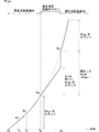
摩耗係数Kは、例えば油圧ポンプ11が経年劣化していく過程などで、変化する。そこで、このステップS31では、過去に算出された摩耗係数Kが、新たに算出された摩耗係数Kに更新される(摩耗係数更新処理)。さらに詳しくは、図5に示すように、ある時刻を時刻T1(第1時刻)とし、時刻T1よりも後の、ある時刻を時刻T2(第2時刻)とする。このとき、時刻T1に(過去に)摩耗係数算出処理(S31、図3参照)で算出した摩耗係数K1が、時刻T2に(新たに)摩耗係数算出処理(S31)で算出した摩耗係数K2に更新される。
(Wear coefficient update process)
The wear coefficient K changes, for example, in the process in which the
補正処理(S40、図3参照)の詳細は後述する。図3に示すように、ステップS41(後述)でNOの場合、ステップS50に進む。 Details of the correction process (S40, see FIG. 3) will be described later. As shown in FIG. 3, if NO in step S41 (described later), the process proceeds to step S50.
ステップS50(検出摩耗量カウント処理)では、金属センサ77に検出された金属の量が、検出摩耗量W検出nとしてカウントされる。カウントされるとは、コントローラ50に値が記憶されることである。
In step S50 (detected wear amount counting process), the amount of metal detected by the
(適正流量範囲内でない場合の処理(S60))
金属センサ77を通る作動油の流量が、適正流量範囲内でない場合(図2のS21でNOの場合)は、金属センサ77で適正な精度で金属の量を検出できない場合がある。この場合の処理について、図4を参照して説明する。
(Processing when the flow rate is not within the appropriate flow rate range (S60))
If the flow rate of the hydraulic oil passing through the
ステップS61では、摩耗係数Kが算出されているか否かが判定される。過去に(今回のフローまでに)摩耗係数Kが算出されたか否かが判定される。例えば、摩耗係数Kn-1が初期値(例えば0)の場合、摩耗係数Kn-1が算出されていないと判定される。摩耗係数Kn-1が初期値でない場合、摩耗係数Kn-1が算出されていると判定される。摩耗係数Kn-1が算出されていない場合(S61でNOの場合)、今回のフローを終了し(ステップSe)、nを1だけ増やし、ステップS15(図2参照)に進み、次回のフローが開始される。摩耗係数Kn-1が算出されている場合(S61でYESの場合)、ステップS63に進む。 In step S61, it is determined whether or not the wear coefficient K has been calculated. It is determined whether or not the wear coefficient K has been calculated in the past (by the current flow). For example, when the wear coefficient K n-1 is an initial value (for example, 0), it is determined that the wear coefficient K n-1 has not been calculated. If the wear coefficient K n-1 is not the initial value, it is determined that the wear coefficient K n-1 has been calculated. If the wear coefficient K n-1 has not been calculated (NO in S61), the current flow is terminated (step Se), n is increased by 1, the process proceeds to step S15 (see FIG. 2), and the next flow. Is started. If the wear coefficient K n-1 has been calculated (YES in S61), the process proceeds to step S63.
ステップS63(演算摩耗量カウント処理)では、図4に示すように、摩耗係数Kを用いて算出(推定)した金属の量を演算摩耗量W演算nとしてカウントする。例えば、演算摩耗量W演算nは次の式により算出される。
W演算n=Kn-1×P×V×T×t (式3)
In step S63 (calculated wear amount counting process), as shown in FIG. 4, the amount of metal calculated (estimated) using the wear coefficient K is counted as the calculated wear amount W calculation n . For example, the calculated wear amount W calculation n is calculated by the following formula.
W operation n = K n-1 × P × V × T × t (Equation 3)
演算摩耗量W演算nの算出に、温度tは用いられなくてもよい。この場合、例えば、演算摩耗量W演算nは、次の式により算出される。
W演算n=Kn-1×P×V×T (式3’)
The temperature t may not be used in the calculation of the calculated wear amount W calculation n . In this case, for example, the calculated wear amount W calculation n is calculated by the following formula.
W operation n = K n-1 x P x V x T (Equation 3')
金属センサ77を通る作動油の流量が適正流量範囲内ではない状態が連続する間(図2に示すステップS21でNOの状態が連続する間)、演算摩耗量W演算nが積算される。積算された演算摩耗量W演算nは、図3に示す補正処理(S40)での補正に使われる(詳細は後述)。次に、ステップS70に進む。
While the flow rate of the hydraulic oil passing through the
ステップS70(合算摩耗量算出処理)では、図2に示すように、合算摩耗量W合算nが算出される。合算摩耗量W合算nは、検出摩耗量W検出および演算摩耗量W演算を合算(積算)した値である。さらに詳しくは、合算摩耗量W合算nは、過去の検出摩耗量W検出および過去の演算摩耗量W演算を合算した値(合算摩耗量W合算n-1)と、今回のフローの検出摩耗量W検出nまたは今回のフローの演算摩耗量W演算nと、を合算した値である。例えば、演算摩耗量W演算nは、次の式により算出される。
W合算n=W合算n-1+W検出n+W演算n (式4)
In step S70 (total wear amount calculation process), as shown in FIG. 2, the total wear amount W total n is calculated. The total wear amount W total n is a value obtained by totaling (integrating) the detected wear amount W detection and the calculated wear amount W calculation . More specifically, the total wear amount W total n is the sum of the past detected wear amount W detection and the past calculated wear amount W calculation (total wear amount W total n-1 ) and the detected wear amount of the current flow. It is a value obtained by adding W detection n or the calculated wear amount W calculation n of the current flow. For example, the calculated wear amount W calculation n is calculated by the following formula.
W total n = W total n-1 + W detection n + W operation n (Equation 4)
式4では、ステップS40(図3参照)からステップS70に進んだ場合、W検出nおよびW演算nは0である(詳細は後述)。ステップS50(図3参照)からステップS70に進んだ場合、W検出nはステップS50でカウントされた値であり、W演算nは0である。ステップS63(図4参照)からステップS70に進んだ場合、W演算nはステップS63でカウントされた値であり、W検出nは0である。 In Equation 4, when the process proceeds from step S40 (see FIG. 3) to step S70, W detection n and W operation n are 0 (details will be described later). When the process proceeds from step S50 (see FIG. 3) to step S70, W detection n is the value counted in step S50, and W operation n is 0. When the process proceeds from step S63 (see FIG. 4) to step S70, the W operation n is the value counted in step S63, and the W detection n is 0.
合算摩耗量W合算nの算出後、各値は次のようになる。添え字がnの値は、添え字がn−1の値に代入され、0にリセットされる。例えば、合算摩耗量W合算nの値は、合算摩耗量W合算n-1に代入され、0にリセットされる。ただし、今回のフローでステップS31の処理が行われず、摩耗係数Knが算出も更新もされなかった場合は、摩耗係数Kn-1の値は変更されない(保持、維持される)。 After calculating the total wear amount W and the total n , each value becomes as follows. A value with a subscript of n is assigned to a value with a subscript of n-1 and reset to 0. For example, the value of the combined wear amount W summing n is substituted into summing wear amount W sum n-1, is reset to 0. However, if the process of step S31 is not performed in this flow and the wear coefficient K n is neither calculated nor updated, the value of the wear coefficient K n-1 is not changed (held and maintained).
異常判定処理(S80)では、油圧ポンプ11が異常(例えば故障)であるか否かが判定される。まず、ステップS81では、合算摩耗量W合算nが、異常判定閾値を超えたか否かが判定される。異常判定閾値は、コントローラ50に予め設定される。例えば、異常判定閾値は、油圧ポンプ11で許容される摩耗量の上限値、またはその近傍の値などである。合算摩耗量W合算nが、異常判定閾値を超えた場合(S81でYESの場合)、油圧ポンプ11が異常であると判定される(ステップS83)。この場合、モニタ41が、異常を報知する。合算摩耗量W合算nが、異常判定閾値を超えない場合(S81でNOの場合)、油圧ポンプ11が正常であると判定される(ステップS85)。ステップS83またはステップS85の後、今回のフローを終了し(ステップSe)、nを1だけ増やし、ステップS15に進み、次回のフローが開始される。
In the abnormality determination process (S80), it is determined whether or not the
(補正処理(S40))
補正処理(S40)について、図5を参照して説明する。時刻T0から時刻Ta(第3時刻)まで、適正流量範囲内(図2のS21でYES)であるとする。時刻T0から時刻Taまでの時間は、検出摩耗量W検出(図3のS50)が、合算摩耗量W合算に合算される(図2のS70)。時刻Taに、摩耗係数算出処理(図3のS31)で摩耗係数Kaが算出される。
(Correction processing (S40))
The correction process (S40) will be described with reference to FIG. It is assumed that the flow rate is within the appropriate flow rate range (YES in S21 of FIG. 2) from the time T0 to the time Ta (third time). For the time from time T0 to time Ta, the detected wear amount W detection (S50 in FIG. 3) is added to the total wear amount W total (S70 in FIG. 2). At time Ta, the wear coefficient Ka is calculated by the wear coefficient calculation process (S31 in FIG. 3).
時刻Taの直後(時刻Taの次回のフロー)から、時刻Tb(第4時刻)の直前(時刻Tbの1回前のフロー)まで、適正流量範囲内ではない(S21でNO)状態が連続したとする。この間は、摩耗係数Kaを用いて算出された演算摩耗量W演算(図4のS63)が、合算摩耗量W合算に合算される(図2のS70)。また、この間は、摩耗係数Kaが更新されない(図3のS31の処理が行われない)(摩耗係数Kn-1が変更されない)。 From immediately after time Ta (next flow of time Ta) to immediately before time Tb (fourth time) (flow one time before time Tb), the state of not being within the proper flow rate range (NO in S21) continued. And. During this period, the calculated wear amount W calculation (S63 in FIG. 4) calculated using the wear coefficient Ka is added to the total wear amount W total (S70 in FIG. 2). Further, during this period, the wear coefficient Ka is not updated (the processing of S31 in FIG. 3 is not performed) (the wear coefficient K n-1 is not changed).
時刻Tb(第4時刻)に、適正流量範囲内ではない(S21でNO)状態から、適正流量範囲内(S21でYES)になったとする。この時刻Tbに摩耗係数算出処理(図3のS31)で摩耗係数Kbが算出される。 It is assumed that at time Tb (fourth time), the state of not being within the proper flow rate range (NO in S21) is changed to within the proper flow rate range (YES in S21). At this time Tb, the wear coefficient Kb is calculated by the wear coefficient calculation process (S31 in FIG. 3).
このとき、摩耗係数Kaと摩耗係数Kbとの差が小さいと(図3のS41でNOの場合)、演算摩耗量W演算nと実際の摩耗量(例えば二点鎖線で示す量)との誤差(乖離)が小さく、油圧ポンプ11が異常か否かの判定(図2のS80)を適切に行える。一方、摩耗係数Kaと摩耗係数Kbとの差が大きいと(図3のS41でYESの場合)、演算摩耗量W演算nと実際の摩耗量との誤差が大きいことにより、油圧ポンプ11が異常か否かの判定(図2のS80)を適切に行えない場合がある。
At this time, if the difference between the wear coefficient Ka and the wear coefficient Kb is small (NO in S41 in FIG. 3), the error between the calculated wear amount W calculation n and the actual wear amount (for example, the amount indicated by the alternate long and short dash line). (Deviation) is small, and it is possible to appropriately determine whether or not the
そこで、摩耗係数Kaを用いて算出された演算摩耗量W演算を補正し、補正摩耗量W補正を算出する(図3のS43、S45)。そして、図3に示すように、補正摩耗量W補正nを用いて、前回までの合算摩耗量W合算n-1を補正する(S47)。そして、補正された合算摩耗量W合算n-1を用いて、油圧ポンプ11が異常か否かの判定(図2のS80)を行う。以下、図3を参照して、補正処理(S40)の各ステップについて説明する。
Therefore, the calculated wear amount W calculation calculated using the wear coefficient Ka is corrected, and the corrected wear amount W correction is calculated (S43, S45 in FIG. 3). Then, as shown in FIG. 3, the corrected wear amount W correction n is used to correct the total wear amount W total n-1 up to the previous time (S47). Then, it is determined whether or not the
ステップS41では、摩耗係数差算出処理と、摩耗係数閾値判定処理と、が行われる。摩耗係数差算出処理では、摩耗係数Kn(図5のKb)と摩耗係数Kn-1(図5のKa)との差(乖離量、差分)が算出される。例えば、摩耗係数Kの差(摩耗係数差)は、次のように算出される。
摩耗係数差=Kn−Kn-1 (式5)
In step S41, the wear coefficient difference calculation process and the wear coefficient threshold value determination process are performed. In the wear coefficient difference calculation process, the difference (deviation amount, difference) between the wear coefficient K n (Kb in FIG. 5) and the wear coefficient K n-1 (Ka in FIG. 5) is calculated. For example, the difference in wear coefficient K (wear coefficient difference) is calculated as follows.
Wear coefficient difference = K n − K n-1 (Equation 5)
摩耗係数閾値判定処理では、摩耗係数差算出処理で(式5で)算出された摩耗係数差が、摩耗係数閾値を超えたか否かが判定される。摩耗係数閾値は、コントローラ50に予め設定される。摩耗係数閾値は、0でもよく、0以外の値でもよく、例えば0以上の値である。摩耗係数差が摩耗係数閾値を超えない場合(S41でNOの場合)、ステップS50に進む。この場合は、例えば、摩耗係数Kを補正する必要がない程度に、摩耗係数Kが変化していない、またはほぼ変化していない場合などである。なお、例えば、摩耗係数Kn-1が初期値(0)の場合は、摩耗係数差にかかわらずステップS50に進んでもよい。摩耗係数差が摩耗係数閾値を超えた場合(S41でYESの場合)、ステップS43に進む。
In the wear coefficient threshold value determination process, it is determined whether or not the wear coefficient difference calculated by the wear coefficient difference calculation process (in Equation 5) exceeds the wear coefficient threshold value. The wear coefficient threshold is preset in the
ステップS43(摩耗係数補正処理)では、摩耗係数Kが補正され、補正摩耗係数K補正が算出される。補正摩耗係数K補正は、図5に示す時刻Taに算出された摩耗係数Ka(摩耗係数Kn-1)と、時刻Tbに算出された摩耗係数Kb(摩耗係数Kn)と、を用いて算出される。補正摩耗係数K補正は、例えば次のように算出される。時刻Taの直後から時刻Tbの直前までの間に、摩耗係数Kが急上昇する場合がある。このとき、時刻Taから時刻Tbまでの間の、どのタイミングで摩耗係数Kが急上昇したかは分からない。そこで、例えば、下記の式6のように、摩耗係数Ka(式6ではKn-1)と摩耗係数Kb(式6ではKn)との平均値を、補正摩耗係数K補正(式6ではK補正n)とする。なお、補正摩耗係数K補正は、摩耗係数Kaと摩耗係数Kbとの平均値でなくてもよい。
K補正n=(Kn+Kn-1)/2 (式6)
In step S43 (wear coefficient correction process), the wear coefficient K is corrected and the corrected wear coefficient K correction is calculated. The correction wear coefficient K correction uses the wear coefficient Ka (wear coefficient K n-1 ) calculated at the time Ta shown in FIG. 5 and the wear coefficient Kb (wear coefficient K n ) calculated at the time Tb. It is calculated. The correction wear coefficient K correction is calculated as follows, for example. The wear coefficient K may rise sharply between immediately after the time Ta and immediately before the time Tb. At this time, it is unknown at what timing the wear coefficient K suddenly rises between the time Ta and the time Tb. Therefore, for example, as shown in the following equation 6, the average value of the wear coefficient Ka (K n-1 in the equation 6) and the wear coefficient Kb (K n in the equation 6) is set to the corrected wear coefficient K correction (in the equation 6). K correction n ). The corrected wear coefficient K correction does not have to be the average value of the wear coefficient Ka and the wear coefficient Kb.
K correction n = (K n + K n-1 ) / 2 (Equation 6)
ステップS45(図3参照、演算摩耗量補正処理)では、ステップS63(図4参照、演算摩耗量カウント処理)でカウントされた演算摩耗量W演算が補正される。そして、補正後の演算摩耗量W演算である補正摩耗量W補正が算出される。補正摩耗量W補正は、補正摩耗係数K補正を用いて算出される。補正摩耗量W補正nは、補正前の摩耗係数Kn-1および補正摩耗係数K補正nを用いて算出される。補正摩耗量W補正nは、補正摩耗係数K補正nを、補正前の摩耗係数Kn-1で割った値を用いて算出される。例えば、補正摩耗量W補正nは、次の式により算出される。
W補正n=W演算n-1/Kn-1×K補正n (式7)
In step S45 (see FIG. 3, calculated wear amount correction process), the calculated wear amount W calculation counted in step S63 (see FIG. 4, calculated wear amount counting process) is corrected. Then, the corrected wear amount W correction, which is the calculated wear amount W calculation after the correction, is calculated. The corrected wear amount W correction is calculated using the corrected wear coefficient K correction . The corrected wear amount W correction n is calculated by using the wear coefficient K n-1 before the correction and the corrected wear coefficient K correction n . The corrected wear amount W correction n is calculated by dividing the corrected wear coefficient K correction n by the wear coefficient K n-1 before the correction. For example, the corrected wear amount W correction n is calculated by the following formula.
W correction n = W operation n-1 / K n-1 × K correction n (Equation 7)
適正流量範囲内でない状態(図2のS21でNO)が連続した場合は、時刻Taの直後から時刻Tbの直前までの間に積算された演算摩耗量W演算が補正されてもよい。例えば、式7の「W演算n-1」を、積算された演算摩耗量W演算に代えてもよい(下記の式8についても同様)。 When the states that are not within the appropriate flow rate range (NO in S21 in FIG. 2) are continuous, the calculated wear amount W calculation accumulated between immediately after the time Ta and immediately before the time Tb may be corrected. For example, "W calculation n-1 " in Equation 7 may be replaced with the integrated calculated wear amount W calculation (the same applies to Equation 8 below).
ステップS47(図3参照、合算摩耗量補正処理)では、図3に示すステップS45で算出された補正摩耗量W補正nを用いて、合算摩耗量W合算n-1が補正される。例えば、補正後の合算摩耗量W合算n-1は、次の式により算出される。
補正後のW合算n-1
=補正前のW合算n-1−W演算n-1+W補正n (式8)
In step S47 (see FIG. 3, total wear amount correction process), the total wear amount W total n-1 is corrected by using the correction wear amount W correction n calculated in step S45 shown in FIG. For example, the corrected total wear amount W total n-1 is calculated by the following formula.
W total after correction n-1
= W total before correction n-1 −W operation n-1 + W correction n (Equation 8)
補正後のW合算n-1が算出された後、時刻Taから時刻Tbの直前までの間に積算されたW演算がリセットされる。なお、例えば、ステップS41でNOの場合、積算されたW演算がリセットされてもよい。ステップS41でYESであっても、演算摩耗量W演算が0であれば(図4のS63の処理を一度も行っていない場合など)、ステップS50に進んでもよい。補正処理(S40)の後、上記のステップS70(図2参照)に進む。補正処理(S40)の後、ステップS50に進んだ後、ステップS70(図2参照)に進んでもよい。 After the corrected W total n-1 is calculated, the W calculation accumulated between the time Ta and immediately before the time Tb is reset. For example, if NO in step S41, the integrated W operation may be reset. Even if YES in step S41, if the calculated wear amount W calculation is 0 (for example, when the process of S63 in FIG. 4 has never been performed), the process may proceed to step S50. After the correction process (S40), the process proceeds to step S70 (see FIG. 2). After the correction process (S40), the process may proceed to step S50 and then to step S70 (see FIG. 2).
(第1の発明の効果)
図1に示す油圧ポンプ異常診断装置1による効果は次の通りである。なお、油圧ポンプ異常診断装置1を構成する機器および配管については図1を参照して説明する。油圧ポンプ異常診断装置1は、油圧ポンプ11と、吐出圧力センサ73と、吐出量取得手段M1と、ドレン管23と、金属センサ77と、金属センサ通過流量取得手段M2と、コントローラ50(演算手段M3)と、を備える。吐出圧力センサ73は、油圧ポンプ11の吐出圧力Pを検出する。吐出量取得手段M1は、油圧ポンプ11の吐出量Vを取得する。ドレン管23は、油圧ポンプ11からリークする作動油が流入するものである。金属センサ77は、ドレン管23に接続され、ドレン管23を流れる作動油中の金属の量を検出する。金属センサ通過流量取得手段M2は、金属センサ77を通る作動油の流量を取得する。
(Effect of the first invention)
The effects of the hydraulic pump abnormality diagnosis device 1 shown in FIG. 1 are as follows. The equipment and piping constituting the hydraulic pump abnormality diagnosis device 1 will be described with reference to FIG. The hydraulic pump abnormality diagnosis device 1 includes a
コントローラ50は、金属センサ通過流量判定処理(図2のS17)と、摩耗係数算出処理(図3のS31)と、検出摩耗量カウント処理(S50)と、を実行する。コントローラ50は、演算摩耗量カウント処理(図4のS63)と、合算摩耗量算出処理(図2のS70)と、異常判定処理(S80)と、を実行する。金属センサ通過流量判定処理(図2のS17)は、金属センサ通過流量取得手段M2に取得された流量が、予め設定された適正流量範囲内であるか否かを判定する処理である。摩耗係数算出処理(図3のS31)は、金属センサ通過流量判定処理で適正流量範囲内であると判定された場合(図2のS21でYESの場合)、摩耗係数Kを算出する処理である。摩耗係数算出処理(図3のS31)は、吐出圧力センサ73に検出された吐出圧力Pと、吐出量取得手段M1に取得された吐出量Vと、金属センサ77に検出された金属の量(検出摩耗量W検出)と、を用いて摩耗係数Kを算出する処理である。検出摩耗量カウント処理(S50)は、金属センサ通過流量判定処理で適正流量範囲内であると判定された場合(図2のS21でYESの場合)、金属センサ77に検出された金属の量を検出摩耗量W検出としてカウントする処理である。
The
[構成1−1]演算摩耗量カウント処理(図4のS63)は、金属センサ通過流量判定処理で適正流量範囲内でないと判定された場合(図2のS21でNOの場合)、摩耗係数Kを用いて算出した金属の量を演算摩耗量W演算としてカウントする処理である。
[構成1−2]合算摩耗量算出処理(図2のS70)は、検出摩耗量W検出および演算摩耗量W演算を合算した合算摩耗量W合算を算出する処理である。異常判定処理(S90)は、合算摩耗量W合算が、予め設定された異常判定閾値を超えたか否かを判定することで、油圧ポンプ11が異常であるか否かを判定する処理である。
[Structure 1-1] In the calculated wear amount counting process (S63 in FIG. 4), when it is determined by the metal sensor passing flow rate determination process that the flow rate is not within the appropriate flow rate range (NO in S21 in FIG. 2), the wear coefficient K This is a process of counting the amount of metal calculated using the above as the calculated wear amount W calculation .
[Structure 1-2] The total wear amount calculation process (S70 in FIG. 2) is a process of calculating the total wear amount W total by adding the detected wear amount W detection and the calculated wear amount W calculation . The abnormality determination process (S90) is a process for determining whether or not the
油圧ポンプ異常診断装置1は、主に上記[構成1−1]を備える。よって、金属センサ77を通る作動油の流量が、予め設定された適正流量範囲内でないと判定された場合(S21でNOの場合)でも、摩耗係数Kを用いて金属の量(演算摩耗量W演算)が算出される。そして、上記[構成1−2]により、演算摩耗量W演算を用いて、油圧ポンプ11が異常であるか否かが判定される。よって、金属センサ77を通る作動油の流量が、適正流量範囲内でない場合でも、油圧ポンプ11が異常であるか否かを判定できる。例えば、金属センサ77を通る作動油の流量が適正流量範囲よりも高い流量(高流量条件下)であっても、油圧ポンプ11が故障したか否かを診断できる。
The hydraulic pump abnormality diagnosis device 1 mainly includes the above [configuration 1-1]. Therefore, even when it is determined that the flow rate of the hydraulic oil passing through the
(第2の発明の効果)
[構成2]コントローラ50は、摩耗係数更新処理(図3のS31)を実行する。摩耗係数更新処理(S31)は、図5に示す時刻T1に摩耗係数算出処理(図3のS31)で算出した摩耗係数K1を、時刻T1よりも後の時刻T2に摩耗係数算出処理(図3のS31)で算出した摩耗係数K2に更新する処理である。
(Effect of the second invention)
[Structure 2] The
上記[構成2]により、摩耗係数Kが変化しても、摩耗係数Kが新たな値に更新される。よって、演算摩耗量カウント処理(図4のS63)で、更新された摩耗係数K(K2)を用いて、演算摩耗量W演算を算出できる。その結果、油圧ポンプ11が異常であるか否かを適切に判定できる。
According to the above [Structure 2], even if the wear coefficient K changes, the wear coefficient K is updated to a new value. Thus, in operation the wear amount counting process (S63 in FIG. 4), using the updated wear coefficient K (K2), can be calculated calculation wear amount W operation. As a result, it can be appropriately determined whether or not the
(第3の発明の効果)
コントローラ50は、摩耗係数差算出処理(図3のS41の一部)と、演算摩耗量補正処理(図3のS45)と、を実行する。摩耗係数差算出処理は、時刻Taよりも後の時刻Tbに摩耗係数算出処理(図3のS31)で算出された摩耗係数Kbと、時刻Taに摩耗係数算出処理(S31)で算出された摩耗係数Kaと、の差を算出する処理である。
[構成3]摩耗係数差算出処理(図3のS31)で算出された差が、予め設定された摩耗係数閾値を超えた場合(図3のS41でYESの場合)、演算摩耗量カウント処理(図4のS63)でカウントした演算摩耗量W演算を補正する処理である。
(Effect of the third invention)
The
[Structure 3] When the difference calculated in the wear coefficient difference calculation process (S31 in FIG. 3) exceeds the preset wear coefficient threshold value (YES in S41 in FIG. 3), the calculated wear amount counting process (S). This is a process for correcting the calculated wear amount W calculation counted in S63) of FIG.
摩耗係数差算出処理で算出された差が、摩耗係数閾値を超えた場合(図3のS41でYESの場合)、演算摩耗量W演算と、実際の摩耗量と、の差異が大きく、油圧ポンプ11が異常であるか否かの判定を適切に行えない場合がある。そこで、油圧ポンプ異常診断装置1は、特に上記[構成3]を備える。よって、補正後の演算摩耗量W演算(補正摩耗量W補正)を用いて、油圧ポンプ11が異常であるか否かを適切に判定できる。いわば、過去に遡って、油圧ポンプ11の異常の判定ができる。
When the difference calculated by the wear coefficient difference calculation process exceeds the wear coefficient threshold value (YES in S41 of FIG. 3), the difference between the calculated wear amount W calculation and the actual wear amount is large, and the hydraulic pump It may not be possible to properly determine whether or not 11 is abnormal. Therefore, the hydraulic pump abnormality diagnosis device 1 particularly includes the above [configuration 3]. Therefore, it is possible to appropriately determine whether or not the
(第4の発明の効果)
[構成4]演算摩耗量補正処理(図3のS45)では、時刻Taに摩耗係数算出処理(図3のS31)で算出された摩耗係数Kaと、時刻Tbに摩耗係数算出処理(図3のS31)で算出された摩耗係数Kbと、を用いて、演算摩耗量W演算が補正される。
(Effect of Fourth Invention)
[Structure 4] In the calculated wear amount correction process (S45 in FIG. 3), the wear coefficient Ka calculated by the wear coefficient calculation process (S31 in FIG. 3) at time Ta and the wear coefficient calculation process at time Tb (FIG. 3). The calculated wear amount W calculation is corrected by using the wear coefficient Kb calculated in S31).
上記[構成4]により、摩耗係数Kaおよび摩耗係数Kbを用いることなく演算摩耗量W演算を補正する場合に比べ、より適切に演算摩耗量W演算を補正できる。 By the Configuration 4], compared with the case of correcting the calculation wear amount W operation without using the wear coefficient Ka and wear coefficients Kb, it can be corrected more appropriately calculating the wear amount W operation.
(第5の発明の効果)
[構成5]油圧ポンプ異常診断装置1は、金属センサ77を通る作動油の温度tを検出する温度センサ75を備える。
(Effect of Fifth Invention)
[Structure 5] The hydraulic pump abnormality diagnosis device 1 includes a
上記[構成5]により、温度センサ75に検出された温度tを、例えば、摩耗係数Kの算出、および、ドレン管23を流れる作動油の流量の算出、の少なくともいずれかなどに用いることができる。
According to the above [Structure 5], the temperature t detected by the
(第6の発明の効果)
[構成6]摩耗係数算出処理(図3のS31)では、温度センサ75に検出された温度tが、摩耗係数Kの算出に用いられる。
(Effect of the sixth invention)
[Structure 6] In the wear coefficient calculation process (S31 in FIG. 3), the temperature t detected by the
上記[構成6]により、金属センサ77を通る作動油の温度tに基づかずに算出した摩耗係数Kから摩耗量を算出する場合に比べ、演算摩耗量W演算(図4のS63参照)を適切に算出できる。例えば摩耗量の推定の精度を向上させることができる。
According to the above [Structure 6], the calculated wear amount W calculation (see S63 in FIG. 4) is more appropriate than the case where the wear amount is calculated from the wear coefficient K calculated without being based on the temperature t of the hydraulic oil passing through the
(第7の発明の効果)
[構成7]金属センサ77の上流と下流との差圧を検出する差圧センサ79を備える。金属センサ通過流量取得手段M2は、温度センサ75に検出された温度tと、金属センサ77の開口面積と、差圧センサ79された差圧と、に基づいてドレン管23を流れる作動油の流量を算出する。
(Effect of the seventh invention)
[Structure 7] A
上記[構成7]により、金属センサ77を通る作動油の流量を取得するために、流量センサを用いる必要がない。例えば、金属が多量に流量センサを通った場合、流量センサが故障(例えば破損)するおそれがあるところ、流量センサを用いない場合はこの問題が生じない。
According to the above [Structure 7], it is not necessary to use the flow rate sensor in order to acquire the flow rate of the hydraulic oil passing through the
(変形例)
上記実施形態の構成は様々に変形されてもよい。図1に示す構成要素の数が変更されてもよく、構成要素の一部が設けられなくてもよい。回路の接続は変更されてもよい。金属センサ77は、図1に示す例では、作動油タンク30に取り付けられるが、作動油タンク30に取り付けられなくてもよい(差圧センサ79も同様)。
(Modification example)
The configuration of the above embodiment may be variously modified. The number of components shown in FIG. 1 may be changed, and some of the components may not be provided. The circuit connections may be changed. In the example shown in FIG. 1, the
吐出量取得手段M1は、油圧ポンプ11が吐出した作動油の流量を検出する流量センサでもよい。金属センサ通過流量取得手段M2は、金属センサ77を通る(ドレン管23を流れる)作動油の流量を検出する流量センサでもよい。
The discharge amount acquisition means M1 may be a flow rate sensor that detects the flow rate of the hydraulic oil discharged by the
第1時刻と第3時刻は同じ時刻でもよく、第2時刻と第4時刻とは同じ時刻でもよい。さらに詳しくは、上記実施形態では、図5に示す時刻T1を第1時刻、時刻T2を第2時刻、時刻Taを第3時刻、時刻Tbを第4時刻というように、第1時刻〜第4時刻を4つの相違する時刻として説明した。一方、時刻Taを第1時刻(摩耗係数Kaが算出される時刻)とすれば、時刻Tbは、第2時刻(摩耗係数Kaが摩耗係数Kbに更新される時刻)である。 The first time and the third time may be the same time, and the second time and the fourth time may be the same time. More specifically, in the above embodiment, the time T1 shown in FIG. 5 is the first time, the time T2 is the second time, the time Ta is the third time, the time Tb is the fourth time, and so on. The time has been described as four different times. On the other hand, if the time Ta is the first time (the time when the wear coefficient Ka is calculated), the time Tb is the second time (the time when the wear coefficient Ka is updated to the wear coefficient Kb).
1 油圧ポンプ異常診断装置
11 油圧ポンプ
23 ドレン管
73 吐出圧力センサ
75 温度センサ
77 金属センサ
79 差圧センサ
M1 吐出量取得手段
M2 金属センサ通過流量取得手段
M3 演算手段
S21 金属センサ通過流量判定処理
S31 摩耗係数算出処理、摩耗係数更新処理
S41 摩耗係数差算出処理および差の判定
S45 演算摩耗量補正処理
S50 検出摩耗量カウント処理
S63 演算摩耗量カウント処理
S70 合算摩耗量算出処理
S80 異常判定処理
T1 時刻(第1時刻)
T2 時刻(第2時刻)
Ta 時刻(第3時刻)
Tb 時刻(第4時刻)
1 Hydraulic pump
T2 time (second time)
Ta time (3rd time)
Tb time (4th time)
Claims (7)
前記油圧ポンプの吐出圧力を検出する吐出圧力センサと、
前記油圧ポンプの吐出量を取得する吐出量取得手段と、
前記油圧ポンプからリークする作動油が流入するドレン管と、
前記ドレン管に接続され、前記ドレン管を流れる作動油中の金属の量を検出する金属センサと、
前記金属センサを通る作動油の流量を取得する金属センサ通過流量取得手段と、
演算手段と、
を備え、
前記演算手段は、
前記金属センサ通過流量取得手段に取得された流量が、予め設定された適正流量範囲内であるか否かを判定する金属センサ通過流量判定処理と、
前記金属センサ通過流量判定処理で適正流量範囲内であると判定された場合、前記吐出圧力センサに検出された吐出圧力と、前記吐出量取得手段に取得された吐出量と、前記金属センサに検出された金属の量と、を用いて摩耗係数を算出する摩耗係数算出処理と、
前記金属センサ通過流量判定処理で適正流量範囲内であると判定された場合、前記金属センサに検出された金属の量を検出摩耗量としてカウントする検出摩耗量カウント処理と、
前記金属センサ通過流量判定処理で適正流量範囲内でないと判定された場合、前記摩耗係数を用いて算出した金属の量を演算摩耗量としてカウントする演算摩耗量カウント処理と、
前記検出摩耗量および前記演算摩耗量を合算した合算摩耗量を算出する合算摩耗量算出処理と、
前記合算摩耗量が、予め設定された異常判定閾値を超えたか否かを判定することで、前記油圧ポンプが異常であるか否かを判定する異常判定処理と、
を実行する、
油圧ポンプ異常診断装置。 With a hydraulic pump
A discharge pressure sensor that detects the discharge pressure of the hydraulic pump and
Discharge amount acquisition means for acquiring the discharge amount of the hydraulic pump, and
A drain pipe into which hydraulic oil leaking from the hydraulic pump flows in,
A metal sensor connected to the drain pipe and detecting the amount of metal in the hydraulic oil flowing through the drain pipe,
A metal sensor passing flow rate acquisition means for acquiring the flow rate of hydraulic oil passing through the metal sensor,
Computational means and
With
The calculation means is
A metal sensor passing flow rate determination process for determining whether or not the flow rate acquired by the metal sensor passing flow rate acquisition means is within a preset appropriate flow rate range, and
When it is determined by the metal sensor passing flow rate determination process that the flow rate is within the appropriate flow rate range, the discharge pressure detected by the discharge pressure sensor, the discharge amount acquired by the discharge amount acquisition means, and the discharge amount detected by the metal sensor are detected. A wear coefficient calculation process that calculates the wear coefficient using the amount of metal that has been generated, and
When the metal sensor passing flow rate determination process determines that the flow rate is within the appropriate flow rate range, the detected wear amount counting process that counts the amount of metal detected by the metal sensor as the detected wear amount, and
When the metal sensor passing flow rate determination process determines that the flow rate is not within the appropriate flow rate range, the calculated wear amount counting process that counts the amount of metal calculated using the wear coefficient as the calculated wear amount, and
The total wear amount calculation process for calculating the total wear amount by adding the detected wear amount and the calculated wear amount, and
Abnormality determination processing for determining whether or not the hydraulic pump is abnormal by determining whether or not the total wear amount exceeds a preset abnormality determination threshold value.
To execute,
Hydraulic pump abnormality diagnostic device.
前記演算手段は、第1時刻に前記摩耗係数算出処理で算出した前記摩耗係数を、前記第1時刻よりも後の第2時刻に前記摩耗係数算出処理で算出した前記摩耗係数に更新する摩耗係数更新処理を実行する、
油圧ポンプ異常診断装置。 The hydraulic pump abnormality diagnostic device according to claim 1.
The calculation means updates the wear coefficient calculated by the wear coefficient calculation process at the first time to the wear coefficient calculated by the wear coefficient calculation process at the second time after the first time. Execute the update process,
Hydraulic pump abnormality diagnostic device.
前記演算手段は、
第3時刻よりも後の第4時刻に前記摩耗係数算出処理で算出された前記摩耗係数と、前記第3時刻に前記摩耗係数算出処理で算出された前記摩耗係数と、の差を算出する摩耗係数差算出処理と、
前記摩耗係数差算出処理で算出された差が、予め設定された摩耗係数閾値を超えた場合、前記演算摩耗量カウント処理でカウントした前記演算摩耗量を補正する演算摩耗量補正処理と、
を実行する、
油圧ポンプ異常診断装置。 The hydraulic pump abnormality diagnostic device according to claim 1 or 2.
The calculation means is
Wear for calculating the difference between the wear coefficient calculated by the wear coefficient calculation process at the fourth time after the third time and the wear coefficient calculated by the wear coefficient calculation process at the third time. Coefficient difference calculation processing and
When the difference calculated by the wear coefficient difference calculation process exceeds a preset wear coefficient threshold value, the calculated wear amount correction process for correcting the calculated wear amount counted by the calculated wear amount counting process and the calculated wear amount correction process.
To execute,
Hydraulic pump abnormality diagnostic device.
前記演算摩耗量補正処理では、前記第3時刻に前記摩耗係数算出処理で算出された前記摩耗係数と、前記第4時刻に前記摩耗係数算出処理で算出された前記摩耗係数と、を用いて前記演算摩耗量が補正される、
油圧ポンプ異常診断装置。 The hydraulic pump abnormality diagnostic device according to claim 3.
In the calculated wear amount correction process, the wear coefficient calculated by the wear coefficient calculation process at the third time and the wear coefficient calculated by the wear coefficient calculation process at the fourth time are used. Calculated wear is corrected,
Hydraulic pump abnormality diagnostic device.
前記金属センサを通る作動油の温度を検出する温度センサを備える、
油圧ポンプ異常診断装置。 The hydraulic pump abnormality diagnostic device according to any one of claims 1 to 4.
A temperature sensor for detecting the temperature of hydraulic oil passing through the metal sensor is provided.
Hydraulic pump abnormality diagnostic device.
前記摩耗係数算出処理では、前記温度センサに検出された温度が、前記摩耗係数の算出に用いられる、
油圧ポンプ異常診断装置。 The hydraulic pump abnormality diagnostic device according to claim 5.
In the wear coefficient calculation process, the temperature detected by the temperature sensor is used for calculating the wear coefficient.
Hydraulic pump abnormality diagnostic device.
前記金属センサの上流と下流との差圧を検出する差圧センサを備え、
前記金属センサ通過流量取得手段は、前記温度センサに検出された温度と、前記金属センサの開口面積と、前記差圧センサに検出された差圧と、に基づいて前記ドレン管を流れる作動油の流量を算出する、
油圧ポンプ異常診断装置。 The hydraulic pump abnormality diagnostic device according to claim 5 or 6.
A differential pressure sensor for detecting the differential pressure between the upstream and downstream of the metal sensor is provided.
The metal sensor passing flow rate acquisition means of the hydraulic oil flowing through the drain pipe based on the temperature detected by the temperature sensor, the opening area of the metal sensor, and the differential pressure detected by the differential pressure sensor. Calculate the flow rate,
Hydraulic pump abnormality diagnostic device.
Priority Applications (1)
| Application Number | Priority Date | Filing Date | Title |
|---|---|---|---|
| JP2017096948A JP6809367B2 (en) | 2017-05-16 | 2017-05-16 | Hydraulic pump abnormality diagnostic device |
Applications Claiming Priority (1)
| Application Number | Priority Date | Filing Date | Title |
|---|---|---|---|
| JP2017096948A JP6809367B2 (en) | 2017-05-16 | 2017-05-16 | Hydraulic pump abnormality diagnostic device |
Publications (2)
| Publication Number | Publication Date |
|---|---|
| JP2018193896A JP2018193896A (en) | 2018-12-06 |
| JP6809367B2 true JP6809367B2 (en) | 2021-01-06 |
Family
ID=64571486
Family Applications (1)
| Application Number | Title | Priority Date | Filing Date |
|---|---|---|---|
| JP2017096948A Active JP6809367B2 (en) | 2017-05-16 | 2017-05-16 | Hydraulic pump abnormality diagnostic device |
Country Status (1)
| Country | Link |
|---|---|
| JP (1) | JP6809367B2 (en) |
Families Citing this family (2)
| Publication number | Priority date | Publication date | Assignee | Title |
|---|---|---|---|---|
| JP7159922B2 (en) * | 2019-03-07 | 2022-10-25 | コベルコ建機株式会社 | OIL EQUIPMENT ABNORMALITY DETERMINATION DEVICE, OIL EQUIPMENT ABNORMALITY DETERMINATION METHOD, AND OIL EQUIPMENT ABNORMALITY DETERMINATION PROGRAM |
| CN116658413B (en) * | 2023-08-01 | 2023-10-03 | 山东鑫亚格林鲍尔燃油系统有限公司 | Hydraulic pump fault detection method |
Family Cites Families (5)
| Publication number | Priority date | Publication date | Assignee | Title |
|---|---|---|---|---|
| JPH0611376A (en) * | 1992-06-26 | 1994-01-21 | Komatsu Ltd | Detecting device for quantity of metal powder in hydraulic circuit |
| JP3414985B2 (en) * | 1997-06-02 | 2003-06-09 | 東芝機械株式会社 | Diagnosis device for hydraulic pump of injection molding machine |
| JP3476702B2 (en) * | 1999-02-24 | 2003-12-10 | 新キャタピラー三菱株式会社 | Pump failure diagnosis device |
| JP4542819B2 (en) * | 2004-05-21 | 2010-09-15 | 株式会社小松製作所 | Hydraulic machine, system and method for monitoring the health status of a hydraulic machine |
| JP2015080780A (en) * | 2013-10-24 | 2015-04-27 | 栗田工業株式会社 | Water treatment condition monitor, water treatment apparatus, method of monitoring water treatment condition, and water treatment method |
-
2017
- 2017-05-16 JP JP2017096948A patent/JP6809367B2/en active Active
Also Published As
| Publication number | Publication date |
|---|---|
| JP2018193896A (en) | 2018-12-06 |
Similar Documents
| Publication | Publication Date | Title |
|---|---|---|
| KR101668826B1 (en) | Fault detection system for actuator | |
| KR102028372B1 (en) | Pressure Flow Control System and More Detection Methods | |
| JP6815881B2 (en) | Fluid pressure drive | |
| KR20100091901A (en) | Flow controller | |
| JP6809367B2 (en) | Hydraulic pump abnormality diagnostic device | |
| JP6848874B2 (en) | Oil vibration diagnostic device and oil vibration diagnostic method | |
| JP2016053308A (en) | Fault diagnosis equipment for hydraulic pump | |
| JP2008063954A (en) | Abnormality diagnostic method of drainage pump and its device | |
| JP2013104369A (en) | Troubleshooting device for plunger pump | |
| JP4088149B2 (en) | Abnormality monitoring method for hydraulic system | |
| JP7457455B2 (en) | Fluid control valve diagnostic device, fluid control device, and fluid control valve diagnostic program | |
| JPWO2019235610A1 (en) | Construction machinery | |
| JP6342266B2 (en) | Fault diagnosis device for hydraulic pump | |
| JP2017223668A (en) | Pressure monitoring apparatus | |
| JP4614758B2 (en) | Drainage pump check valve abnormality detection system | |
| JP5515375B2 (en) | Construction equipment filter clogging detection device | |
| JP5971534B2 (en) | Flow measuring device | |
| JP7067505B2 (en) | Fuel pump diagnostic device | |
| JP2510736B2 (en) | Water removal control monitoring system for dialysis equipment | |
| JPH0568710A (en) | Ultrafiltration control and supervision system of dialyzator | |
| JP3924419B2 (en) | Pumping station monitoring system | |
| JP4008449B2 (en) | Evaluation method of scale adhesion | |
| KR101659567B1 (en) | Apparatus and Method for detecting leak | |
| JP6410293B2 (en) | Sensor calibration system, method, and program | |
| JP7453484B2 (en) | Pump monitoring system and method that correlates the current operating state of a pump system with one or more failure scenarios |
Legal Events
| Date | Code | Title | Description |
|---|---|---|---|
| A621 | Written request for application examination |
Free format text: JAPANESE INTERMEDIATE CODE: A621 Effective date: 20200114 |
|
| A977 | Report on retrieval |
Free format text: JAPANESE INTERMEDIATE CODE: A971007 Effective date: 20201023 |
|
| TRDD | Decision of grant or rejection written | ||
| A01 | Written decision to grant a patent or to grant a registration (utility model) |
Free format text: JAPANESE INTERMEDIATE CODE: A01 Effective date: 20201110 |
|
| A61 | First payment of annual fees (during grant procedure) |
Free format text: JAPANESE INTERMEDIATE CODE: A61 Effective date: 20201123 |
|
| R150 | Certificate of patent or registration of utility model |
Ref document number: 6809367 Country of ref document: JP Free format text: JAPANESE INTERMEDIATE CODE: R150 |