JP6806236B2 - Lighting equipment and methods, exposure equipment and methods, and device manufacturing methods - Google Patents
Lighting equipment and methods, exposure equipment and methods, and device manufacturing methods Download PDFInfo
- Publication number
- JP6806236B2 JP6806236B2 JP2019506258A JP2019506258A JP6806236B2 JP 6806236 B2 JP6806236 B2 JP 6806236B2 JP 2019506258 A JP2019506258 A JP 2019506258A JP 2019506258 A JP2019506258 A JP 2019506258A JP 6806236 B2 JP6806236 B2 JP 6806236B2
- Authority
- JP
- Japan
- Prior art keywords
- illumination
- illumination light
- light
- optical system
- mask
- Prior art date
- Legal status (The legal status is an assumption and is not a legal conclusion. Google has not performed a legal analysis and makes no representation as to the accuracy of the status listed.)
- Active
Links
- 238000000034 method Methods 0.000 title claims description 42
- 238000004519 manufacturing process Methods 0.000 title claims description 15
- 238000005286 illumination Methods 0.000 claims description 277
- 230000003287 optical effect Effects 0.000 claims description 181
- 238000009826 distribution Methods 0.000 claims description 51
- 239000000758 substrate Substances 0.000 claims description 23
- 239000013307 optical fiber Substances 0.000 claims description 20
- 230000004907 flux Effects 0.000 claims description 15
- 238000012545 processing Methods 0.000 claims description 6
- 230000003247 decreasing effect Effects 0.000 claims 1
- 239000000835 fiber Substances 0.000 description 32
- 238000002347 injection Methods 0.000 description 15
- 239000007924 injection Substances 0.000 description 15
- 238000010586 diagram Methods 0.000 description 14
- 239000004973 liquid crystal related substance Substances 0.000 description 11
- 230000000052 comparative effect Effects 0.000 description 7
- 239000011521 glass Substances 0.000 description 6
- 229920002120 photoresistant polymer Polymers 0.000 description 4
- 239000004065 semiconductor Substances 0.000 description 4
- QSHDDOUJBYECFT-UHFFFAOYSA-N mercury Chemical compound [Hg] QSHDDOUJBYECFT-UHFFFAOYSA-N 0.000 description 3
- 229910052753 mercury Inorganic materials 0.000 description 3
- 210000004027 cell Anatomy 0.000 description 2
- 238000007687 exposure technique Methods 0.000 description 2
- 238000012986 modification Methods 0.000 description 2
- 230000004048 modification Effects 0.000 description 2
- 238000000206 photolithography Methods 0.000 description 2
- 210000001747 pupil Anatomy 0.000 description 2
- 239000010409 thin film Substances 0.000 description 2
- 238000012546 transfer Methods 0.000 description 2
- 238000000018 DNA microarray Methods 0.000 description 1
- 230000005540 biological transmission Effects 0.000 description 1
- 239000003795 chemical substances by application Substances 0.000 description 1
- 210000002858 crystal cell Anatomy 0.000 description 1
- 230000007423 decrease Effects 0.000 description 1
- 230000000694 effects Effects 0.000 description 1
- 230000003760 hair shine Effects 0.000 description 1
- 238000003384 imaging method Methods 0.000 description 1
- 239000011159 matrix material Substances 0.000 description 1
- 239000000203 mixture Substances 0.000 description 1
- 230000002093 peripheral effect Effects 0.000 description 1
- 239000003504 photosensitizing agent Substances 0.000 description 1
- 230000001360 synchronised effect Effects 0.000 description 1
- 230000002194 synthesizing effect Effects 0.000 description 1
Images


Classifications
-
- G—PHYSICS
- G03—PHOTOGRAPHY; CINEMATOGRAPHY; ANALOGOUS TECHNIQUES USING WAVES OTHER THAN OPTICAL WAVES; ELECTROGRAPHY; HOLOGRAPHY
- G03F—PHOTOMECHANICAL PRODUCTION OF TEXTURED OR PATTERNED SURFACES, e.g. FOR PRINTING, FOR PROCESSING OF SEMICONDUCTOR DEVICES; MATERIALS THEREFOR; ORIGINALS THEREFOR; APPARATUS SPECIALLY ADAPTED THEREFOR
- G03F7/00—Photomechanical, e.g. photolithographic, production of textured or patterned surfaces, e.g. printing surfaces; Materials therefor, e.g. comprising photoresists; Apparatus specially adapted therefor
- G03F7/70—Microphotolithographic exposure; Apparatus therefor
- G03F7/70058—Mask illumination systems
- G03F7/70141—Illumination system adjustment, e.g. adjustments during exposure or alignment during assembly of illumination system
-
- G—PHYSICS
- G02—OPTICS
- G02B—OPTICAL ELEMENTS, SYSTEMS OR APPARATUS
- G02B19/00—Condensers, e.g. light collectors or similar non-imaging optics
-
- G—PHYSICS
- G03—PHOTOGRAPHY; CINEMATOGRAPHY; ANALOGOUS TECHNIQUES USING WAVES OTHER THAN OPTICAL WAVES; ELECTROGRAPHY; HOLOGRAPHY
- G03F—PHOTOMECHANICAL PRODUCTION OF TEXTURED OR PATTERNED SURFACES, e.g. FOR PRINTING, FOR PROCESSING OF SEMICONDUCTOR DEVICES; MATERIALS THEREFOR; ORIGINALS THEREFOR; APPARATUS SPECIALLY ADAPTED THEREFOR
- G03F7/00—Photomechanical, e.g. photolithographic, production of textured or patterned surfaces, e.g. printing surfaces; Materials therefor, e.g. comprising photoresists; Apparatus specially adapted therefor
- G03F7/20—Exposure; Apparatus therefor
-
- G—PHYSICS
- G03—PHOTOGRAPHY; CINEMATOGRAPHY; ANALOGOUS TECHNIQUES USING WAVES OTHER THAN OPTICAL WAVES; ELECTROGRAPHY; HOLOGRAPHY
- G03F—PHOTOMECHANICAL PRODUCTION OF TEXTURED OR PATTERNED SURFACES, e.g. FOR PRINTING, FOR PROCESSING OF SEMICONDUCTOR DEVICES; MATERIALS THEREFOR; ORIGINALS THEREFOR; APPARATUS SPECIALLY ADAPTED THEREFOR
- G03F7/00—Photomechanical, e.g. photolithographic, production of textured or patterned surfaces, e.g. printing surfaces; Materials therefor, e.g. comprising photoresists; Apparatus specially adapted therefor
- G03F7/70—Microphotolithographic exposure; Apparatus therefor
- G03F7/70058—Mask illumination systems
- G03F7/70091—Illumination settings, i.e. intensity distribution in the pupil plane or angular distribution in the field plane; On-axis or off-axis settings, e.g. annular, dipole or quadrupole settings; Partial coherence control, i.e. sigma or numerical aperture [NA]
- G03F7/701—Off-axis setting using an aperture
-
- G—PHYSICS
- G03—PHOTOGRAPHY; CINEMATOGRAPHY; ANALOGOUS TECHNIQUES USING WAVES OTHER THAN OPTICAL WAVES; ELECTROGRAPHY; HOLOGRAPHY
- G03F—PHOTOMECHANICAL PRODUCTION OF TEXTURED OR PATTERNED SURFACES, e.g. FOR PRINTING, FOR PROCESSING OF SEMICONDUCTOR DEVICES; MATERIALS THEREFOR; ORIGINALS THEREFOR; APPARATUS SPECIALLY ADAPTED THEREFOR
- G03F7/00—Photomechanical, e.g. photolithographic, production of textured or patterned surfaces, e.g. printing surfaces; Materials therefor, e.g. comprising photoresists; Apparatus specially adapted therefor
- G03F7/70—Microphotolithographic exposure; Apparatus therefor
- G03F7/70058—Mask illumination systems
- G03F7/7015—Details of optical elements
Description
本発明は、照明光で物体を照明する照明技術、照明技術を用いる露光技術、及び露光技術を用いるデバイス製造技術に関する。 The present invention relates to a lighting technique for illuminating an object with illumination light, an exposure technique using the lighting technique, and a device manufacturing technique using the exposure technique.
従来、液晶表示素子、半導体素子、薄膜磁気ヘッド等の電子デバイスを製造するためのフォトリソグラフィ工程で、照明装置により照明されたマスクのパターンを、投影光学系を介してフォトレジスト等の感光剤が塗布されたプレート等の基板に転写するために露光装置が用いられている。
従来の照明装置として、水銀ランプからの照明光束の断面形状を制御するための複数の円錐又は角錐状の光学部材からなる光学系を備え、輪帯照明を行う場合に照明光の利用効率を高めるために、輪帯状の照明光源の形状に応じて、その光学系を用いて照明光束の断面形状を制御する照明装置が使用されている(例えば特許文献1参照)。Conventionally, in a photolithography process for manufacturing electronic devices such as liquid crystal display elements, semiconductor elements, and thin film magnetic heads, a photosensitive agent such as a photoresist is applied to a mask pattern illuminated by an illumination device via a projection optical system. An exposure apparatus is used to transfer to a substrate such as a coated plate.
As a conventional lighting device, an optical system composed of a plurality of conical or prismatic optical members for controlling the cross-sectional shape of the illumination light flux from the mercury lamp is provided to improve the utilization efficiency of the illumination light when performing ring-shaped illumination. Therefore, a lighting device that controls the cross-sectional shape of the illuminating luminous flux by using the optical system according to the shape of the ring-shaped illuminating light source is used (see, for example, Patent Document 1).
露光装置では輪帯照明以外の照明方法も使用される。このような場合にも、照明光の利用効率を高めることを考慮することが望まれている。 Lighting methods other than ring-shaped lighting are also used in the exposure apparatus. Even in such a case, it is desired to consider increasing the utilization efficiency of the illumination light.
第1の態様によれば、マスクを照明する照明装置であって、照明光を発生する光源と、その照明光の傾き角を調整する光学系と、その光学系を介したその照明光を集光する第1集光光学系と、その光学系を介したその照明光を、その照明光のその傾き角を維持してその第1集光光学系に射出する光学部材と、その第1集光光学系から射出したその照明光の開口数を調整する開口絞りと、開口数が調整されたその照明光をそのマスクに導く第2集光光学系と、を備え、その光学部材は、その光学系を介したその照明光を、その照明光のその傾き角を維持して複数の光束に分岐し、 その第1集光光学系、その開口絞り、及びその第2集光光学系を、その光学部材で分岐されるその複数の光束に対応して複数組備え、そのマスクの複数の照明領域を照明する照明装置が提供される。 According to the first aspect, it is an illumination device that illuminates a mask, a light source that generates illumination light, an optical system that adjusts the tilt angle of the illumination light, and the illumination light that collects the illumination light via the optical system. The first condensing optical system that shines, the optical member that emits the illumination light through the optical system to the first condensing optical system while maintaining the tilt angle of the illumination light, and the first collection thereof. The optical member comprises an aperture throttle for adjusting the number of openings of the illumination light emitted from the optical optical system and a second condensing optical system for guiding the illumination light with the adjusted number of openings to the mask. The illumination light via the optical system is branched into a plurality of light beams while maintaining the inclination angle of the illumination light, and the first focusing optical system, the aperture aperture, and the second focusing optical system are divided into a plurality of light beams. plural sets provided corresponding to the plurality of light beams branched by the optical member, the illumination device is provided you illuminate a plurality of illumination regions of the mask.
第2の態様によれば、マスクのパターンを基板に露光する露光装置であって、第1の態様の照明装置と、その照明装置で照明されたそのマスクのパターンの像を基板に形成する投影光学系と、を備える露光装置が提供される。
第3の態様によれば、マスクを照明する照明方法であって、光源から発生された照明光の傾き角を調整することと、その傾き角が調整されたその照明光を、その照明光のその傾き角を維持する光学部材を介して射出することと、射出されたその照明光を集光することと、その照明光の開口数を調整することと、開口数が調整されたその照明光をそのマスクに導くことと、その光学部材を用いて、その傾き角が調整されたその照明光を複数の光束に分岐することと、を含み、その複数の光束を用いて、そのマスクの複数の照明領域を照明する照明方法が提供される。
According to the second aspect, it is an exposure device that exposes a mask pattern to a substrate, and is a projection that forms an image of the illumination device of the first aspect and the mask pattern illuminated by the illumination device on the substrate. An exposure apparatus comprising an optical system is provided.
According to the third aspect, it is an illumination method for illuminating a mask, in which the tilt angle of the illumination light generated from the light source is adjusted, and the illumination light for which the tilt angle is adjusted is used as the illumination light. Ejecting through an optical member that maintains the tilt angle, condensing the emitted illumination light, adjusting the number of openings of the illumination light, and adjusting the number of openings of the illumination light. and directing to the mask, with the optical member, the method comprising: branching the illumination light that the inclination angle is adjusted to a plurality of light beams, only containing, by using the plurality of light beams, the mask A lighting method for illuminating a plurality of lighting areas is provided.
第4の態様によれば、マスクのパターンを基板に露光する露光方法であって、第3の態様の照明方法を用いてそのマスクを照明することと、照明されたそのマスクのパターンの像を基板に形成することと、を含む露光方法が提供される。 According to the fourth aspect, it is an exposure method for exposing a mask pattern to a substrate, in which the mask is illuminated by using the illumination method of the third aspect, and an image of the illuminated mask pattern is displayed. An exposure method including forming on a substrate is provided.
一実施形態について、図1〜図9(B)を参照して説明する。図1は、本実施形態に係る露光装置EXを示す斜視図である。本実施形態では、露光装置EXが、複数の反射屈折型の部分投影光学系を有する投影光学系PLに対してマスクMと感光剤が塗布された基板としての平板状のプレートPとを同期移動させつつ、マスクMに形成されたパターンの像をプレートPに転写するステップ・アンド・スキャン方式の露光装置であるものとして説明する。 One embodiment will be described with reference to FIGS. 1 to 9 (B). FIG. 1 is a perspective view showing an exposure apparatus EX according to the present embodiment. In the present embodiment, the exposure apparatus EX synchronously moves the mask M and the flat plate-shaped plate P as the substrate coated with the photosensitizer with respect to the projection optical system PL having a plurality of reflection-refraction type partial projection optical systems. It will be described as a step-and-scan type exposure apparatus that transfers an image of a pattern formed on the mask M to the plate P.
以下では、図1において、プレートPに平行な平面内で直交するようにX軸、Y軸を取り、その平面(XY平面)に垂直にZ軸を取って説明する。一例として、XY平面が水平面に平行な面に設定され、Z軸が鉛直線に平行に設定される。また、この実施形態ではマスクM及びプレートPを同期移動させる方向である走査方向をX軸に平行な方向(X方向)に設定している。このとき、走査方向に直交する非走査方向はY軸に平行な方向(Y方向)である。 Hereinafter, in FIG. 1, the X-axis and the Y-axis are taken so as to be orthogonal to each other in a plane parallel to the plate P, and the Z-axis is taken perpendicular to the plane (XY plane). As an example, the XY plane is set to a plane parallel to the horizontal plane and the Z axis is set to be parallel to the vertical line. Further, in this embodiment, the scanning direction, which is the direction in which the mask M and the plate P are synchronously moved, is set to the direction parallel to the X axis (X direction). At this time, the non-scanning direction orthogonal to the scanning direction is a direction parallel to the Y axis (Y direction).
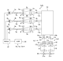
露光装置EXは、マスクステージMST(図3参照)に支持されたマスクMのパターン面(以下、マスク面ともいう)を均一な照度分布の照明光で照明するための照明装置ILAと、投影光学系PLと、装置全体の動作を制御するコンピュータよりなる制御部30とを備えている。照明装置ILAは、マスク面にY方向(非走査方向)に沿って配置された第1列の複数(ここでは4個)の照明領域21a,21c,21e,21gと、第1列の照明領域21a〜21gに対して走査方向(X方向)にずれた状態で、照明領域21a〜21gの間に位置する第2列の複数(ここでは3つ)の照明領域(不図示)とを照明する。このように照明装置ILAはマスク面の7つの照明領域を照明するが、照明領域の配置及び個数は任意である。
The exposure device EX includes an illumination device ILA for illuminating the pattern surface (hereinafter, also referred to as a mask surface) of the mask M supported by the mask stage MST (see FIG. 3) with illumination light having a uniform illuminance distribution, and projection optics. It includes a system PL and a
本実施形態では、後述のように投影光学系PL内に視野絞りが配置されているため、照明領域21a〜21gは、その視野絞りのマスク面における像よりもわずかに大きい形状であればよい。照明装置ILAは、図2に示すように、超高圧水銀ランプよりなる3つの光源2a,2b,2cを備えている。光源2a,2b,2cから射出した照明光3a,3b,3cは、それぞれ楕円鏡4a、4b,4cにより集光される。光源2a〜2cは、楕円鏡4a〜4cの第1焦点位置に配置されており、楕円鏡4a,4b,4cの第2焦点位置には光源2a,2b,2cの光源像5a,5b,5cが形成される。マスクMを照明しない期間では、楕円鏡4a,4b,4cの第2焦点の近くに配置されたシャッタ(不図示)によって照明光3a,3b,3cは遮光される。なお、光源2a,2b,2cの個数は任意であり、光源は一つ(例えば光源2aのみ)でもよい。
In the present embodiment, since the field diaphragm is arranged in the projection optical system PL as described later, the
光源像5a,5b,5cから発散光として射出される照明光3a,3b,3cは、それぞれ変倍光学系8a,8b,8cによりライトガイドファイバ10の入射端12a,12b,12cに集光される。変倍光学系8a,8b,8cは、それぞれ光源像5a,5b,5cの倍率が可変の像(以下、光源像という)9a,9b,9cを入射端12a,12b,12cの入射面に形成する。変倍光学系8a〜8cは、一例として駆動部6aによって光軸に沿って移動可能な前群レンズ系6、及び駆動部7aによって光軸に沿って移動可能な後群レンズ系7を有するズームレンズ(ズーム光学系)である。制御部30が、駆動部6a,7aを介して前群レンズ系6及び後群レンズ系7の位置を制御することで、変倍光学系8a〜8cの倍率を制御できる。
The
ここで、変倍光学系8aが最小倍率のときの光源像9aの高さ(像高)をy1、このときの光源像9aを形成する照明光3aの光軸に対する最大の傾き角をα1とする。また、変倍光学系8aの倍率がその倍率よりも高い最大倍率のときの光源像9aの高さをy2、このときの照明光3aの光軸に対する最大の傾き角をα2とする。最大の傾き角とは、いわゆる錐角の1/2でもある。なお、光源像9aの光強度分布が正規分布(ガウス分布)状である場合、光源像9aの高さとは、その光強度分布のうちで光強度が最大強度の例えば10%〜50%程度になる位置、又は例えば30%程度になる位置の間隔とみなすことも可能である。変倍光学系8aが正弦条件を満たすものとすると、次の関係が成立する。
Here, the height (image height) of the
y1・sinα1=y2・sinα2 …(1)
ここでは高さy2が高さy1より高いため、式(1)より、傾き角α2は傾き角α1よりも小さくなる。このことから、変倍光学系8a〜8cは、倍率可変の光源像9a〜9cを形成することによって、入射端12a〜12cに入射する照明光の最大の傾き角を制御又は調整できる光学系でもある。本実施形態では、変倍光学系8a〜8cは互いに同じ倍率になるように制御される。y1 ・ sinα1 = y2 ・ sinα2… (1)
Here, since the height y2 is higher than the height y1, the tilt angle α2 is smaller than the tilt angle α1 according to the equation (1). From this, the variable magnification
光伝送部材としてのライトガイドファイバ10は、多数の光ファイバ素線11(図5(A)参照)をランダムに束ねて構成されたファイババンドルであって、3つの入射端12a,12b,12cと、複数(ここでは7つ)の照明領域に対応した複数(ここでは7つ)の射出端(図2においては、射出端14a,14Bのみを示す。)とを有し、入射端12a〜12cから受光した照明光3a〜3cをその複数の射出端に分配する。これによって、各照明光3a〜3cの少なくとも一部は、それぞれその複数の射出端から射出され、照明装置ILAは、複数の光源2a〜2cから各々発せられる照明光を混合して射出することができる。ここでは、ライトガイドファイバ10は、入射端12a〜12cから受光した各照明光を複数の射出端へほぼ等しい光量比で分配して射出させるように構成されているものとする。
The
また、光ファイバ素線11は、それぞれ入射する光束の最大の傾き角と、射出される光束の最大の傾き角とがほぼ等しくなるように、入射する光束の傾き角を維持して射出させるものである。このため、ライトガイドファイバ10の入射端12a〜12cに入射する照明光3a〜3cの最大の傾き角と、その複数の射出端から射出される照明光の最大の傾き角とはほぼ等しい。また、一例として、変倍光学系8a〜8cから射出される照明光は、それぞれ主光線が光軸に平行になる状態で、すなわちいわゆるテレセントリックな状態で、対応する入射端12a〜12cに入射する。これによって、ライトガイドファイバ10の各光ファイバ素線11の伝送可能な入射角の範囲内に照明光を均一に入射させることができる。また、変倍光学系8a〜8cから射出される照明光の最大の傾き角は、光ファイバ素線11の伝送可能な最大の入射角(傾き角)よりも小さい範囲で制御される。
Further, the
ライトガイドファイバ10の複数の射出端14a,14b等から射出された照明光20a,20c等のそれぞれは、マスクMの部分的な照明領域21a,21c等を照明する複数(ここでは7つ)の互いに同じ構成の部分照明光学系IL1〜IL7(ただし、部分照明光学系IL2,IL4〜IL7は図示省略)に入射する。部分照明光学系IL1〜IL7は、後述する部分投影光学系PL1〜PL7にそれぞれ対応付けられ、走査方向に直交する非走査方向(Y方向)に沿って千鳥格子状に配置されている。
Each of the
部分照明光学系IL1,IL3では、ライトガイドファイバ10の射出端14a,14bから射出した照明光20a.20cは、それぞれコリメートレンズであるインプットレンズ15によって集光されて平行光束に変換された後、オプティカルインテグレータであるフライアイレンズ16に入射する。フライアイレンズ16に入射した照明光20a,20cは、フライアイレンズ16を構成する多数のレンズエレメントによって波面分割され、その射出面近傍の後側焦点面(照明光学系の射出瞳面)に複数の光源像からなる二次光源(面光源)を形成する。その後側焦点面に開口絞り17が配置されている。制御部30は、駆動部17aを介して開口絞り17の開口の大きさ及び形状を制御する。これによって、部分照明光学系IL1,IL3によってマスクMを照明する照明光の開口数NAを制御できる。以下では、照明光の開口数NAは、コヒーレンスファクタであるσ値(マスクを照明する照明光の開口数を、投影光学系のマスク側の開口数で割った値)を用いて表すものとする。このため、開口絞り17はσ絞りと呼ぶこともできる。なお、輪帯照明を行う場合には、開口絞り17を輪帯状の大きさ可変の開口を有する輪帯照明用の開口絞り(不図示)と交換してもよい。
In the partial illumination optical systems IL1 and IL3, the
開口絞り17の開口から射出された照明光20a,20cは、コンデンサーレンズ18を介して、マスクM上の対応する照明領域21a,21cをほぼ均一の照度分布で照明する。なお、図示しない部分照明光学系IL2,IL4〜IL7の構成は部分照明光学系IL1と同一であり、部分照明光学系IL2,IL4〜IL7も部分照明光学系IL1と同様に、マスクM上の各々対応する照明領域をほぼ均一の照度分布で照明する。
The illumination lights 20a and 20c emitted from the aperture of the
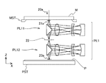
部分照明光学系IL1〜IL7のそれぞれに対応するマスクM上の照明領域21a〜21gからの照明光は、それぞれ部分投影光学系PL1〜PL7に入射する。図3は、部分投影光学系PL1の構成を示す図である。図3に示すように、部分投影光学系PL1は、マスク面の対応する照明領域21a内に設けられたパターンの中間像を視野絞り22の開口部に形成する第1反射屈折型光学系PL11と、この第1反射屈折型光学系PL11と協働して、プレートステージPSTに支持されたプレートPの露光領域23aにマスクMのパターンの像を等倍正立像として結像する第2反射屈折光学系PL12とを備えている。また、部分投影光学系PL2〜PL7は、部分投影光学系PL1と同一の構成を有しており、マスク面の各々対応する照明領域内に形成されたパターンの像をプレートP上に結像する。なお、部分投影光学系PL1〜PL7は、非走査方向に沿って千鳥格子状に配置されている。
Illumination light from the
図2において、制御部30には、光源2a〜2cに対して電力の供給を行う電源装置32が接続されている。制御部30は、プレートPの露光又は照明装置ILAのキャリブレーションを行う場合等に、電源装置32を介して光源2a〜2cを点灯させる。なお、必要露光量が小さい場合には、光源2a〜2cのうち少なくとも一つの光源のみを点灯させることも可能である。
In FIG. 2, a
露光時の基本的な動作として、制御部30は、照明光のσ値等及び変倍光学系8a〜8cの倍率を含む照明条件を設定し(詳細後述)、光源2a〜2cを点灯させる。そして、照明装置ILAによってマスクMを照明し、マスクMを支持するマスクステージMST及びプレートPを支持するプレートステージPSTを駆動して、マスクM及びプレートPを部分投影光学系PL1〜PL7に対して走査方向に同期移動させること(走査露光)と、プレートPを非走査方向又は走査方向に移動させること(ステップ移動)とを繰り返すことで、ステップ・アンド・スキャン方式でマスクMに形成されたパターンの像をプレートPの複数の被露光領域に露光する。
As a basic operation during exposure, the
また、照明装置ILAのキャリブレーションを行う場合には、一例として、照明領域21a〜21gのそれぞれの複数の位置に照度センサ(不図示)を配置する。そして、光源2a〜2cを点灯させて、σ値を変化させた場合、及び変倍光学系8a〜8cの倍率を変化させた場合において、そられの照度センサで計測される照度分布が目標とする分布に対して所定の許容範囲内に収まるように、変倍光学系8a〜8c及び部分照明光学系IL1〜IL7の調整を行うことで、照度分布が均一になる。
Further, when calibrating the lighting device ILA, as an example, illuminance sensors (not shown) are arranged at a plurality of positions of the
以下、本実施形態の照明装置ILAの照明条件の設定を含む照明方法及び露光装置EXを用いる露光方法の動作の一例につき図4のフローチャートを参照して説明する。その動作は制御部30によって制御される。
まず、光源2a〜2cを点灯させていない状態で、図4のステップ102において、露光対象のマスクMのパターンの種類及び微細度等に応じて、照明装置ILAの部分照明光学系IL1〜IL7の開口絞り17を用いて、照明光のσ値を制御する。なお、輪帯照明を行う場合には、開口絞り17を輪帯照明用の開口絞り(不図示)と交換してもよい。ここでは、図5(A)に示すように、開口絞り17の例えば円形の開口の直径を最大値にして、σ値を最大値NA1(例えば0.8〜0.9程度)に設定し、大σ照明を行うものとする。大σ照明を行う場合には、ライトガイドファイバ10の射出端14aから射出される照明光がインプットレンズ15を介して平行光束となってフライアイレンズ16の入射面の最も広い範囲(開口絞り17の最大の開口に対向する領域よりもわずかに広い範囲)を照明する必要がある。このため、射出端14aから射出される照明光の最大の傾き角を調整可能な範囲内の最大値に設定する必要がある。Hereinafter, an example of the operation of the lighting method including the setting of the lighting conditions of the lighting device ILA of the present embodiment and the operation of the exposure method using the exposure device EX will be described with reference to the flowchart of FIG. The operation is controlled by the
First, in the state where the light sources 2a to 2c are not turned on, in
そして、ステップ104において、開口絞り17によって設定されるσ値に応じて、変倍光学系8a〜8cの倍率、ひいてはライトガイドファイバ10の入射端12a〜12cに形成される光源像9a〜9cを形成する照明光3a〜3cの最大の傾き角を調整する。開口絞り17として輪帯照明用の開口絞りを使用する場合、そのσ値としては、輪帯状の開口の外径で定まるσ値を使用してもよい。ここでは、σ値が最大値NA1に設定されているため、変倍光学系8a〜8cの倍率は変倍可能な範囲で最小値に設定され、照明光3a〜3cの最大の傾き角は調整可能な範囲内で最大値α1に設定される。図5(A)において、変倍光学系8aの焦点距離はf1に設定され、光源像9aの高さは調整可能な範囲内の最小値y1に設定されている。
Then, in
ライトガイドファイバ10を構成する各光ファイバ素線11では、入射光束の最大の傾き角と、射出光束の最大の傾き角とはほぼ等しい。このため、開口絞り17の開口径を最大にした場合に、ライトガイドファイバ10の射出端14aから射出される照明光20aはインプットレンズ15を介してその最大の開口を照明可能なフライアイレンズ16の入射面の領域に入射する。また、入射端12aに形成される光源像9aの光強度分布(照度分布)D1は、ほぼ軸対称の正規分布状であり、中央部分が強く、周辺部分に向かって急激に弱くなっている。光源像9aの高さが最小値y1の場合、光強度分布D1は、最大値に対して10%程度以下の部分が入射端12aの入射面の外側に広がるが、入射する照明光3aの大部分(より正確には入射する照明光3a〜3cをランダムに合成した光束)が射出端14a等から射出される。
In each
射出端14aから射出される照明光20aのフライアイレンズ16の入射面での光強度分布C31は、光軸から離れるにつれてわずかに強くなり、その外側で急激に弱くなるほぼ軸対称の分布である。光強度分布C31は、開口絞り17の開口に対向する領域でほぼ均一な値とみなすことができ、開口絞り17の開口には、射出端14aから最大の傾き角がほぼα1で射出される照明光20aの大部分が入射する。このため、開口絞り17の開口を通過してコンデンサーレンズ18を介してマスクMに入射する照明光20aの、ライトガイドファイバ10に入射する照明光3aに対する割合である照明光の利用効率(以下、照明効率ともいう)は高くなっている。
The light intensity distribution C31 on the incident surface of the fly-
そして、ステップ106において、光源2a〜2cを点灯させ、照明装置ILAによって光源2a〜2cからの照明光3a〜3cで、変倍光学系8a〜8c、ライトガイドファイバ10、部分照明光学系IL1〜IL8のインプットレンズ15、フライアイレンズ16、開口絞り17、及びコンデンサーレンズ18を介してマスクMを照明する。そして、ステップ108において、投影光学系PLによってマスクMのパターンの像でプレートPを露光しつつ、マスクM及びプレートPを投影光学系PLに対して同期移動することで、プレートPが露光される。この際に、最大のσ値の照明光を用いて高い照明効率でマスクMを照明できるため、マスクMに形成されたパターンを高いスループット(生産性)で光精度にプレートPに露光できる。
Then, in
次に、例えば露光対象のマスクMのパターンがコンタクトホールのパターンのような微細な孤立パターンを含むような場合には、いわゆる小σ照明を行うために、ステップ102において、図5(B)に示すように、開口絞り17の例えば円形の開口の直径を最小値にして、σ値を最小値NA2(例えば0.05〜0.1程度)に設定する。この場合、射出端14aから射出される照明光はインプットレンズ15を介して平行光束となって、フライアイレンズ16の入射面の最も小さい領域(開口絞り17の最小の開口に対向する領域よりもわずかに広い領域)を照明すればよいため、射出端14aから射出される照明光の最大の傾き角は調整可能な範囲内の最小値α2に設定すればよい。そこで、ステップ104においては、変倍光学系8a〜8cの倍率は変倍可能な範囲で最大値に設定され、照明光3a〜3cの最大の傾き角は最小値α2に設定される。図5(B)において、変倍光学系8aの焦点距離はf2に設定され、光源像9aの高さは最大値y2に設定される。
Next, for example, when the pattern of the mask M to be exposed includes a fine isolated pattern such as a contact hole pattern, in order to perform so-called small σ illumination, in
この際に入射端12aに形成される光源像9aの光強度分布D2は、図5(A)の光強度分布D1を倍率比y2/y1で拡大したほぼ軸対称の正規分布状である。その光強度分布D2は、最大値に対して35%程度以下の部分が、入射端12aの入射面の外側に広がり、入射する照明光3a〜3cのうちの例えば60%程度が射出端14a等から射出される。光源像9aの高さy2を光強度が最大値のほぼ30%の部分の間隔とすると、高さy2の光源像9aは、入射端12aの幅よりもわずかに大きくなる。
The light intensity distribution D2 of the
しかしながら、この場合に、射出端14aから射出される照明光20aの最大の傾き角はほぼ最小値α2であり、照明光20aの大部分は、インプットレンズ15を介して、フライアイレンズ16の入射面において、開口絞り17の最小の開口に対向する領域に入射する。この場合、射出端14aから射出される照明光20aのフライアイレンズ16の入射面での光強度分布C11は、図5(A)の光強度分布C31を半径方向に圧縮したようなほぼ軸対称の分布である。光強度分布C11は、開口絞り17の最小の開口に対向する領域でほぼ均一な値とみなすことができ、開口絞り17の開口には、射出端14aから最大の傾き角がほぼα2で射出される照明光20aの大部分が入射する。このため、入射端12aに入射する照明光3aの光量損失がある程度生じても、開口絞り17の最小の開口を通過してコンデンサーレンズ18を介してマスクMに入射する照明光20aの照明光3aに対する利用効率は高くなっている。その後、ステップ106及び108を行うことで、例えば孤立的なパターンを含むパターンを高いスループットで高精度にプレートPに露光できる。
However, in this case, the maximum tilt angle of the
ここで、比較例として、図6(A)に示すように、変倍光学系8aの倍率を図5(A)の場合と同じく最小に設定して(照明光3aの最大の傾き角を最大値α1に設定して)、開口絞り17でσ値を最小値NA2に設定した場合を想定する。この比較例においては、射出端14aから射出される照明光20aのフライアイレンズ16の入射面での光強度分布C31は、開口絞り17の最小の開口に対向する領域の外側の領域16Aaでもかなり強くなっている。このため、射出端14aから射出される照明光20aのうちで開口絞り17の開口を通過できるのは例えば45%程度となる。
Here, as a comparative example, as shown in FIG. 6 (A), the magnification of the variable magnification
このため、本実施形態の図5(B)のように変倍光学系8aの倍率を高くした場合のマスクMに入射する照明光20aの照明効率は、図6(A)の比較例に対してほぼ30%(=(60/45−1)・100)程度改善されることになる。本実施形態では、3つの光源2a〜2cが使用されているが、照明効率が例えば30%改善される場合には、2つの光源2a,2bのみを点灯させて露光を行うことも可能になるため、光源2a〜2cの寿命を延ばすことも可能になる。
Therefore, the luminous efficiency of the
また、図6(B)は、図5(A)、(B)の入射端12aでの照明光3aの光強度分布D1,D2を相対光強度で表したものであり、図6(B)の横軸は入射端12aの中心位置を0として中心からの距離を相対値で表したものである。横軸の値が50の位置が、一例として入射端12aのエッジ部の位置である。また、図6(B)の光強度分布D3は、図6(A)の比較例の場合に、開口絞り17の開口を通過した照明光と、フライアイレンズ16に入射する照明光との光量比で光強度分布D1を圧縮した分布である。位置±50の内側で光強度分布D2を積分して得られる光量が本実施形態で得られる光量であり、光強度分布D3を積分して得られる光量が比較例で得られる光量であり、この結果からも本実施形態によって照明効率が改善されることが分かる。
Further, FIG. 6B shows the light intensity distributions D1 and D2 of the
また、図6(C)は、図5(A)、(B)のフライアイレンズ16の入射面での照明光20aの光強度分布C31,C11を相対光強度で表したものであり、図6(C)の横軸はその入射面の中心位置を0として中心からの距離をσ値で表したものである。光強度分布C31,C11は、σ値が0.88と0.65での値が等しくなるように相対強度が調整されている。この場合、σ値が0.5の位置での光強度分布C31,C11の値を平均光強度又は平均照度とすると、光強度分布C31,C11の平均照度はほぼ等しくなっている。
Further, FIG. 6C shows the light intensity distributions C31 and C11 of the
次に、ステップ102において、開口絞り17を用いてσ値を最大値NA1と最小値NA2との間の任意の値NA3に設定する場合には、ステップ104において、変倍光学系8a〜8cの倍率を図5(A)の場合の最小値(β1とする)と、図5(B)の場合の最大値(β2とする)との間の値β3に設定してもよい。一例としてβ3は次式で表されるように、σ値NA3が次第に小さくなるのに応じて、次第に大きく設定され、ライトガイドファイバ10に入射する照明光の最大の傾き角は次第に小さく設定される。
Next, in
β3=β1+(NA1−NA3)(β2−β1)/(NA1−NA2) …(2)
これによって、どのようなσ値で照明を行う場合でも、σ値(照明条件)に応じて高い照明効率でマスクMを照明することができ、マスクMのパターンを高いスループットで高精度にプレートPに露光できる。β3 = β1 + (NA1-NA3) (β2-β1) / (NA1-NA2)… (2)
As a result, the mask M can be illuminated with high illumination efficiency according to the σ value (illumination condition) regardless of the σ value, and the pattern of the mask M can be plated with high throughput and high accuracy. Can be exposed to.
また、図7(A)は図5(A)の部分照明光学系IL1を示す拡大図、図7(B)は図7(A)のライトガイドファイバ10の射出端14aを正面から見た拡大図であり、図7(A)においては、フライアイレンズ16を構成する一部の互いに同じ形状のレンズエレメント16aが拡大して示されている。図7(B)に示すように、射出端14aは、多数の光ファイバ素線11を規則的に束ねて構成されている。図7(A)において、射出端14aはインプットレンズ15及びレンズエレメント16aによって、レンズエレメント16aの射出面(開口絞り17の配置面であるいわゆる瞳面)に結像される。また、レンズエレメント16aの入射面は、レンズエレメント16a及びコンデンサーレンズ18によってマスクMの照明領域21aに結像されるため、照明領域21aが露光視野(図3の視野絞り22の開口と共役な領域)よりもわずかに大きくなるように、フライアイレンズ16の各レンズエレメント16aの形状が決定される。
Further, FIG. 7 (A) is an enlarged view showing the partial illumination optical system IL1 of FIG. 5 (A), and FIG. 7 (B) is an enlarged view of the
ライトガイドファイバ10の入射端12aの光強度分布は変倍光学系8aによって変更される。ここでは、一例として、大σ照明時の最大光強度の10%程度までの光強度の光が入射する光ファイバ素線11から射出される光によって、インプットレンズ15及びフライアイレンズ16を介して開口絞り17の配置面に形成される光源像を照明に寄与する有効な光源像とみなす。また、射出端14aの全部の光ファイバ素線11から射出される光がそれぞれ有効な光源像を形成する場合、その光が入射する範囲にあるフライアイレンズ16のレンズエレメント16aの射出面に形成される有効な光源像の数n1は、射出端14aを構成する光ファイバ素線11の数n2と同じである。
The light intensity distribution of the
以下では、レンズエレメント16aの射出面に形成される有効な光源像の数n1の、射出端14aを構成する光ファイバ素線11の数n2に対する比率(=n1/n2)を、レンズエレメント16aにおける光ファイバ素線11からの照明光の充填率γと称する。本実施形態では、一例として、充填率γが1(100%)を維持するように、変倍光学系8aの倍率(入射端12aに入射する照明光の最大の傾き角)が調整される。
このとき、輪帯照明、大σ照明、又は小σ照明を行う場合に、開口絞り17の開口内にあるフライアイレンズ16のレンズエレメント16aの射出面には、それぞれ図8(A)、図8(B)、又は図8(C)に示すように、互いに同じ最大の密度分布(図7(B)の光ファイバ素線11の密度分布に対応する分布)で有効な光源像24が形成される。なお、図8(A)では、開口絞り17の開口が輪帯状の開口17cに設定されている。輪帯照明又は大σ照明を行う場合、変倍光学系8a〜8cからライトガイドファイバ10の入射端12a〜12cに入射する照明光の最大の傾き角は、小σ照明を行う場合に比べて大きく設定される。In the following, the ratio (= n1 / n2) of the number n1 of the effective light source images formed on the emission surface of the
At this time, in the case of ring-shaped illumination, large σ illumination, or small σ illumination, the injection surfaces of the
また、説明の便宜上、図8(A)〜(C)、及び後述の図9(A)、(B)において、フライアイレンズ16の各レンズエレメント16aは、開口17b,17cに対して実際よりも大きく表されている。
このように、本実施形態では、輪帯照明、大σ照明、又は小σ照明を行う場合の光ファイバ素線11からの照明光の充填率γは共通に1となる範囲で、変倍光学系8aの倍率が調整されている。この場合、開口絞り17の開口内の有効な光源像14の数が最大であるため、マスクMにおける照度分布の均一性が良好である。なお、充填率γはほぼ1(例えば0.9〜1)でもよい。Further, for convenience of explanation, in FIGS. 8 (A) to 8 (C) and FIGS. 9 (A) and 9 (B) described later, the
As described above, in the present embodiment, the charge ratio γ of the illumination light from the
ただし、ライトガイドファイバ10の入射端12a〜12cに入射する照明光の光強度は中心部分が最大で、周辺に向かうほど小さくなっている。そのため、入射端12aを構成する多数の光ファイバ素線11のうちで、例えば大σ照明時の最大値に対して70%程度以上、70〜40%、及び40〜10%程度の光強度の照明光3aが入射する光ファイバ素線11からの照明光で形成される光源像をそれぞれ光源像24A,24B,24Cとする。このとき、図5(A)に示すように、σ値を大きく設定する場合には、フライアイレンズ16の射出面において、開口絞り17の開口17b内のレンズエレメント16aの射出面には、図9(A)に示すように、光源像24A,24B,24Cがランダムな配置で形成される。
However, the light intensity of the illumination light incident on the incident ends 12a to 12c of the
また、ライトガイドファイバ10の射出端14aから射出される照明光は、フライアイレンズ16の複数のレンズエレメント16a(光学要素)の入射口(大きい開口17b内にある部分の複数のレンズエレメント16aの入射面)の大きさよりも広い領域に分布している。
これに対して、図5(B)に示すように、σ値を小さく設定する場合には、フライアイレンズ16の射出面において、開口絞り17の開口17b内のレンズエレメント16aの射出面には、図9(B)に示すように、ほぼ中程度の光強度の光源像24Bが規則的な配置で形成される。また、ライトガイドファイバ10の射出端14aから射出される照明光は、小さい開口17b内にある部分のフライアイレンズ16の複数のレンズエレメント16aの入射口の大きさよりも広い領域に分布している。このため、小σ照明ではフライアイレンズ16の各レンズエレメント16aの射出面に形成される光源像24Bの光強度が図9(A)の場合より均一であるため、照度分布がより均一化されることになる。Further, the illumination light emitted from the
On the other hand, as shown in FIG. 5B, when the σ value is set small, the ejection surface of the fly-
また、比較例のように、開口数NA2の小σ照明を行う際に、図9(A)に点線で示すように、単に開口絞り17の開口17bを小さくする場合には、ライトガイドファイバ10から開口17bの外側に入射する照明光の多くが遮光されるため、照明光の利用効率は低下することになる。
Further, as in the comparative example, when performing small σ illumination with a numerical aperture of NA2, as shown by a dotted line in FIG. 9A, when simply reducing the
上述のように、本実施形態のマスクMを照明する照明装置ILAは、照明光を発生する光源2aと、ステップ104において照明光の最大の傾き角を調整する変倍光学系8aと、ステップ106において変倍光学系8aを介した照明光を集光して平行光束にするインプットレンズ15(以下、第1集光光学系ともいう)と、ステップ106において、変倍光学系8aを介した照明光を、その照明光の最大の傾き角を維持してインプットレンズ15に射出するライトガイドファイバ10(以下、光学部材ともいう)と、ステップ102において、その照明光の開口数(σ値)を調整する開口絞り17と、ステップ106において、その開口数が制御された照明光をマスクMに導くコンデンサーレンズ18(以下、第2集光光学系ともいう)とを備えている。
As described above, the illumination device ILA that illuminates the mask M of the present embodiment includes a light source 2a that generates illumination light, a variable magnification
本実施形態の照明装置ILAによれば、照明光の開口数を小さくした小σ照明を行う場合に、変倍光学系8aによってその照明光の最大の傾き角を小さくすることによって、開口絞り17の開口に入射する照明光の割合を大きくすることができ、照明光の利用効率を高めることができる。このため、マスクMをより大きい照度で照明できる。また、同じ照度でマスクMを照明する場合には、光源2aの寿命を長くできるとともに、複数の光源2a〜2cを使用する場合に、使用する光源の数を減らして照明装置ILAの小型化及び低コスト化を図ることができる。また、ライトガイドファイバ10を用いているため、光源2aとマスクMとを離すことができ、マスクMの熱膨張を抑制できる。
According to the illumination device ILA of the present embodiment, when performing small σ illumination in which the number of apertures of the illumination light is reduced, the maximum tilt angle of the illumination light is reduced by the variable magnification
また、本実施形態のマスクMのパターンをプレートPに露光する露光装置EXは、ステップ102〜106において、マスクMを照明する照明装置ILAと、ステップ108において、照明装置ILAで照明されたマスクMのパターンの像をプレートPに形成する投影光学系PLと、を備えている。露光装置EXによれば、照明装置ILAにおける照明光の利用効率が高いため、照明光の照度を高めることで、高いスループットで高精度にマスクMのパターンをプレートPに露光できる。また、照明光の照度が従来と同じ場合には、照明装置ILAを小型化及び低コスト化できるため、露光装置EXをより小型化及び低コスト化できる。
Further, the exposure device EX that exposes the pattern of the mask M of the present embodiment to the plate P is the lighting device ILA that illuminates the mask M in
また、ライトガイドファイバ10は複数の入射端12a〜12c及び複数の射出端14a,14b等を備えているため、複数の光源2a〜2cからの照明光をランダムに混合して、複数の部分照明光学系IL1〜IL7用の光束に容易に分岐できる。
また、複数のレンズエレメント16aを含むフライアイレンズ16を備えているため、マスクMの照明領域における照明光の照度分布をより均一にできる。Further, since the
Further, since the fly-
なお、上述の実施形態では、次のような変形が可能である。
上述の実施形態の変倍光学系8aとしては、図10(A)に示すように、3枚のレンズよりなる前群レンズ系6Aと、3枚のレンズよりなる後群レンズ系7Aとを有し、倍率調整時には、例えば後群レンズ系7Aの位置を調整する変倍光学系8Aaを使用することができる。In the above-described embodiment, the following modifications are possible.
As shown in FIG. 10A, the variable magnification
さらに、変倍光学系8aとしては、光源像5aと光源像9aとの間の光路上で、光源像の中間像を形成するタイプの光学系を使用することもできる。
また、上述の実施形態では、照明光の最大の傾き角を制御するために変倍光学系8aが使用されているが、変倍光学系8aの代わりに、図10(B)に示すように、光学系を部分的に交換して倍率を切り換える方式のリレー光学系8Baを使用してもよい。リレー光学系8Baは、前群レンズ系6Aと、レンズ7Ba及び2枚のレンズを有するレンズ群7Bbよりなる第1の後群レンズ系7Bと、レンズ7Ca及び7Cbよりなる第2の後群レンズ系7Cとを有する。そして、倍率が低いときには、前群レンズ系6Aと第1の後群レンズ系7Bとを用いて、光源像9aを形成し、倍率が高いときには、第1の後群レンズ系7Bの代わりに第2の後群レンズ系7Cを用いて光源像9aを形成する。このように交換式のリレー光学系8Baを使用する場合には、傾き角を制御するための光学系を安価に製造できる。Further, as the variable magnification
Further, in the above-described embodiment, the variable magnification
また、上述の実施形態の変倍光学系8aの例えば前群レンズ系6と後群レンズ系7との間に、米国特許第5,719,704号明細書に開示されているように、また、図10(A)に点線で示すように、2つの円錐状のプリズム状の光学部材7B1,7B2からなる光学系(アキシコン系)を設けてもよい。この際に、通常照明を行う場合には、その2つの光学部材7B1,7B2を密着させ、輪帯照明を行う場合には、その2つの光学部材7B1,7B2の間隔を調整して、前群レンズ系6と後群レンズ系7との間を通過する照明光3aの断面形状を大きさが可変の輪帯状としてもよい。この場合、ライトガイドファイバ10の射出端14aから射出される照明光20aはインプットレンズ15を介してフライアイレンズ16の入射面の輪帯状の領域に入射する。そして、輪帯照明を行う場合に、開口絞りの輪帯状の開口の大きさに応じてその2つの光学部材7B1,7B2の間隔を調整することで、輪帯照明を行う場合の照明光の利用効率をさらに改善できる。
Also, as disclosed in US Pat. No. 5,719,704, between, for example, the front group lens system 6 and the rear group lens system 7 of the dash-dotted
また、上述の実施形態では、オプティカルインテグレータとしてフライアイレンズ16が使用されているが、フライアイレンズ16の代わりにマイクロレンズアレイ、又はロッドインテグレータ等を使用してもよい。
上述の実施形態では、光源2a〜2cとして超高圧水銀ランプが使用されているが、光源2a〜2cとしては、他の任意の放電ランプ等のランプを使用できる。また、光源2a〜2cとして、発光ダイオード(LED)等を使用することも可能である。また、光源2a〜2cとして、固体レーザ、気体レーザ、又は半導体レーザ等のレーザ光源を使用してもよい。また、照明光としてレーザ光の高調波等を使用することも可能である。Further, in the above-described embodiment, the fly-
In the above-described embodiment, the ultra-high pressure mercury lamp is used as the light source 2a to 2c, but as the light source 2a to 2c, a lamp such as any other discharge lamp can be used. It is also possible to use light emitting diodes (LEDs) or the like as the light sources 2a to 2c. Further, as the light sources 2a to 2c, a laser light source such as a solid-state laser, a gas laser, or a semiconductor laser may be used. It is also possible to use a harmonic of a laser beam or the like as the illumination light.
そして、光源としてレーザ光源を使用して、照明光の最大の傾き角を大きく設定する場合には、一例として、図10(C)に示すように、レーザ光源(不図示)から発生する平行光束よりなるレーザビームLBの光路上に、微細な次第にピッチが小さくなる同心円状(ゾーンプレート状)の位相型の凹凸が形成された回折格子8Cを配置する。回折格子8Cの最小のピッチは、最大の傾き角に応じて規定される。
When a laser light source is used as the light source and the maximum tilt angle of the illumination light is set large, as an example, as shown in FIG. 10C, a parallel light beam generated from the laser light source (not shown). On the optical path of the laser beam LB composed of the laser beam LB, a
そして、レーザ光源を使用して照明光の最大の傾き角を小さく設定する場合には、レーザビームLBの光路上に、回折格子8Cと同様の同心円状の位相型の凹凸が形成されるとともに、その最小のピッチは回折格子8Cよりも大きい回折格子8Dを配置する。この変形例では、回折格子8Cを使用する場合には、最大の傾き角が大きい照明光を生成でき、回折格子8Dを使用する場合には、最大の傾き角が小さい照明光を生成できるため、上述の実施形態と同様の効果を得ることができる。
When the maximum tilt angle of the illumination light is set small by using a laser light source, concentric phase-type irregularities similar to those of the
また、上述の実施形態においては、マルチレンズ式の走査型露光装置を例として説明したが、走査型露光装置の他に、マスクMとプレートPとを静止した状態でマスクMのパターンを露光し、プレートPを順次ステップ移動させるステップ・アンド・リピート型の露光装置に上述の実施形態を適用することもできる。また、照明装置の光源として3つの光源を用いているが、照明装置が1つ、2つ、又は4つ以上の光源を備えていてもよい。また、上述の実施形態においては、ライトガイドファイバが7つの射出端を有しているが、ライトガイドファイバの射出端は、1つ以上あればその数はいくつでも良い。 Further, in the above-described embodiment, the multi-lens type scanning exposure apparatus has been described as an example, but in addition to the scanning exposure apparatus, the pattern of the mask M is exposed while the mask M and the plate P are stationary. The above-described embodiment can also be applied to a step-and-repeat type exposure apparatus in which the plate P is sequentially moved in steps. Further, although three light sources are used as the light sources of the lighting device, the lighting device may include one, two, or four or more light sources. Further, in the above-described embodiment, the light guide fiber has seven injection ends, but the number of injection ends of the light guide fiber may be any number as long as it is one or more.
また、上述の実施形態では、複数の光源2a〜2cからの照明光を複数の部分照明光学系IL1〜IL7用の光束に分岐しているが、一つの光源2aからの照明光で一つの部分照明光学系IL1を介してマスクMを照明し、マスクMのパターンを一つの結像光学系(例えば部分投影光学系PL1と同様の光学系)を介してプレートPに転写してもよい。この場合には、ライトガイドファイバ10を設けることなく、変倍光学系8aからの照明光3aを、直接にインプットレンズ15を介してフライアイレンズ16に入射させてもよい。
Further, in the above-described embodiment, the illumination light from the plurality of light sources 2a to 2c is branched into the light beams for the plurality of partial illumination optical systems IL1 to IL7, but one portion is provided by the illumination light from one light source 2a. The mask M may be illuminated via the illumination optical system IL1 and the pattern of the mask M may be transferred to the plate P via one imaging optical system (for example, an optical system similar to the partial projection optical system PL1). In this case, the
次に、上述の実施形態にかかる露光装置又は露光方法を用いたデバイス製造方法について説明する。図11は、液晶表示素子等の液晶デバイスの製造工程を示すフローチャートである。図11に示すように、液晶デバイスの製造工程では、パターン形成工程(ステップ200)、カラーフィルタ形成工程(ステップ202)、セル組立工程(ステップ204)、及びモジュール組立工程(ステップ206)を順次行う。 Next, a device manufacturing method using the exposure apparatus or the exposure method according to the above-described embodiment will be described. FIG. 11 is a flowchart showing a manufacturing process of a liquid crystal device such as a liquid crystal display element. As shown in FIG. 11, in the liquid crystal device manufacturing process, a pattern forming step (step 200), a color filter forming step (step 202), a cell assembling step (step 204), and a module assembling step (step 206) are sequentially performed. ..
ステップ200のパターン形成工程では、プレートとしてフォトレジストが塗布されたガラス基板上に、上述の露光装置又は露光方法を用いて回路パターンおよび電極パターン等の所定のパターンを形成する。このパターン形成工程には、上述の実施形態の露光装置又は露光方法を用いてフォトレジスト層にパターンを転写する露光工程と、パターンが転写されたプレートの現像を行い、パターンに対応する形状のフォトレジスト層をマスク層として生成する現像工程と、この現像されたフォトレジスト層を介してガラス基板の表面を加工する加工工程とが含まれている。
In the pattern forming step of
ステップ202のカラーフィルタ形成工程では、R(赤)、G(緑)、B(青)に対応する3つのドットの組をマトリクス状に多数配列するか、またはR、G、Bの3本のストライプのフィルタの組を水平走査方向に複数配列したカラーフィルタを形成する。
ステップ204のセル組立工程では、ステップ200によって所定パターンが形成されたガラス基板と、ステップ202によって形成されたカラーフィルタとを用いて液晶パネル(液晶セル)を組み立てる。具体的には、例えばガラス基板とカラーフィルタとの間に液晶を注入することで液晶パネルを形成する。In the color filter forming step of
In the cell assembly step of
ステップ206のモジュール組立工程では、ステップ204によって組み立てられた液晶パネルに対し、この液晶パネルの表示動作を行わせる電気回路およびバックライト等の各種部品を取り付ける。このように本実施形態のデバイス製造方法では、上述の実施形態の露光装置EX、又は露光方法を用いて、所定のパターンをガラス基板に形成することと、その所定のパターンを介してそのガラス基板を加工することと、を含んでいる。本実施形態の露光装置EX又は露光方法によれば、高い照明効率で露光を行うことができるため、電子デバイスを高いスループットで高精度に製造できる。
In the module assembly step of
また、上述の実施形態の露光装置EX又は露光方法は、半導体デバイスを製造する際にも適用できる。また、上述の実施形態は、半導体デバイス製造用又は液晶デバイス製造用の露光装置への適用に限定されることなく、例えば、プラズマディスプレイ等のディスプレイ装置用の露光装置や、撮像素子(CCD等)、マイクロマシーン、薄膜磁気ヘッド、及びDNAチップ等の各種デバイスを製造するための露光装置にも広く適用できる。更に、上述の実施形態は、各種デバイスの製造に用いるマスク(フォトマスク、レチクル等)をフォトリソグラフィ工程を用いて製造する際の露光装置にも適用することができる。 Further, the exposure apparatus EX or the exposure method of the above-described embodiment can also be applied when manufacturing a semiconductor device. Further, the above-described embodiment is not limited to application to an exposure device for manufacturing a semiconductor device or a liquid crystal device, for example, an exposure device for a display device such as a plasma display, an image sensor (CCD, etc.). , Micromachines, thin film magnetic heads, and exposure equipment for manufacturing various devices such as DNA chips. Further, the above-described embodiment can also be applied to an exposure apparatus for manufacturing a mask (photomask, reticle, etc.) used for manufacturing various devices by using a photolithography step.
2a,2b,2c…光源、4a,4b,4c…楕円鏡、8a〜8c…変倍光学系、10…ライトガイドファイバ、12a,12b,12c…入射端、14a,14b…射出端、15…インプットレンズ、16…フライアイレンズ、17…開口絞り、18…コンデンサーレンズ、30…制御部、32…電源装置、EX…露光装置、ILA…照明装置、IL1,IL3…部分照明光学系、PL…投影光学系、PL1〜PL7…部分投影光学系、M…マスク、P…プレート 2a, 2b, 2c ... light source, 4a, 4b, 4c ... elliptical mirror, 8a to 8c ... variable magnification optical system, 10 ... light guide fiber, 12a, 12b, 12c ... incident end, 14a, 14b ... emission end, 15 ... Input lens, 16 ... fly-eye lens, 17 ... aperture aperture, 18 ... condenser lens, 30 ... control unit, 32 ... power supply device, EX ... exposure device, ILA ... lighting device, IL1, IL3 ... partial illumination optical system, PL ... Projection optical system, PL1 to PL7 ... Partial projection optical system, M ... Mask, P ... Plate
Claims (27)
照明光を発生する光源と、
前記照明光の傾き角を調整する光学系と、
前記光学系を介した前記照明光を集光する第1集光光学系と、
前記光学系を介した前記照明光を、前記照明光の前記傾き角を維持して前記第1集光光学系に射出する光学部材と、
前記第1集光光学系から射出した前記照明光の開口数を調整する開口絞りと、
開口数が調整された前記照明光を前記マスクに導く第2集光光学系と、
を備え、
前記光学部材は、前記光学系を介した前記照明光を、前記照明光の前記傾き角を維持して複数の光束に分岐し、
前記第1集光光学系、前記開口絞り、及び前記第2集光光学系を、前記光学部材で分岐される前記複数の光束に対応して複数組備え、
前記マスクの複数の照明領域を照明する、照明装置。 A lighting device that illuminates a mask
A light source that generates illumination light and
An optical system that adjusts the tilt angle of the illumination light,
A first condensing optical system that condenses the illumination light via the optical system,
An optical member that emits the illumination light through the optical system to the first condensing optical system while maintaining the inclination angle of the illumination light.
An aperture diaphragm that adjusts the numerical aperture of the illumination light emitted from the first condensing optical system, and
A second condensing optical system that guides the illumination light with an adjusted numerical aperture to the mask,
Equipped with a,
The optical member branches the illumination light through the optical system into a plurality of luminous fluxes while maintaining the inclination angle of the illumination light.
A plurality of sets of the first condensing optical system, the aperture diaphragm, and the second condensing optical system are provided corresponding to the plurality of light fluxes branched by the optical member.
A lighting device that illuminates a plurality of lighting areas of the mask .
前記光学部材を通過した前記照明光は、前記第1集光光学系の複数の前記光学要素の入射口の大きさよりも広い領域に分布する、請求項1に記載の照明装置。 The first condensing optical system has an optical element group including a plurality of optical elements that make the illuminance distribution of the illumination light uniform.
The lighting device according to claim 1, wherein the illumination light that has passed through the optical member is distributed in a region wider than the size of the incident ports of the plurality of optical elements of the first condensing optical system.
前記光源及び前記光学系を、前記光学部材の前記複数の入射端に対応して複数組備える、請求項1に記載の照明装置。 The optical member has a plurality of incident ends and has a plurality of incident ends.
The lighting device according to claim 1 , further comprising a plurality of sets of the light source and the optical system corresponding to the plurality of incident ends of the optical member.
前記光学部材の射出端を構成する前記光ファイバ素線の数と、前記光学要素群の複数の前記光学要素のそれぞれの射出端に形成される光源像の数とがほぼ等しい範囲で、前記開口絞りで前記照明光の開口数を調整する、請求項2に記載の照明装置。 The optical member is configured by bundling a plurality of optical fiber strands.
The numerical aperture is within a range in which the number of the optical fiber strands constituting the emission end of the optical member and the number of light source images formed at the emission ends of the plurality of optical elements of the optical element group are substantially equal to each other. The lighting device according to claim 2, wherein the numerical aperture of the illumination light is adjusted by an optical fiber.
請求項1〜11のいずれか一項に記載の照明装置と、
前記照明装置で照明された前記マスクのパターンの像を基板に形成する投影光学系と、を備える露光装置。 An exposure device that exposes a mask pattern to a substrate.
The lighting device according to any one of claims 1 to 11 .
An exposure device including a projection optical system that forms an image of the mask pattern illuminated by the lighting device on a substrate.
前記投影光学系を、前記複数の照明領域に対応して複数備え、
前記複数の照明領域の配列方向に交差する方向に、前記マスクと前記基板とを相対的に走査するステージ装置を備える請求項12に記載の露光装置。 The illuminator illuminates a plurality of illumination areas of the mask.
A plurality of the projection optical systems are provided corresponding to the plurality of illumination areas.
The exposure apparatus according to claim 12 , further comprising a stage apparatus that relatively scans the mask and the substrate in a direction intersecting the arrangement directions of the plurality of illumination regions.
光源から発生された照明光の傾き角を調整することと、
前記傾き角が調整された前記照明光を、前記照明光の前記傾き角を維持する光学部材を介して射出することと、
射出された前記照明光を集光することと、
前記照明光の開口数を調整することと、
開口数が調整された前記照明光を前記マスクに導くことと、
前記光学部材を用いて、前記傾き角が調整された前記照明光を複数の光束に分岐することと、を含み、
前記複数の光束を用いて、前記マスクの複数の照明領域を照明する、照明方法。 It is a lighting method that illuminates the mask.
Adjusting the tilt angle of the illumination light generated from the light source
The illumination light whose tilt angle is adjusted is emitted through an optical member that maintains the tilt angle of the illumination light.
Condensing the emitted illumination light and
Adjusting the numerical aperture of the illumination light and
To guide the illumination light with the adjusted numerical aperture to the mask,
Using said optical member, seen containing a to branch, the said illumination light the inclination angle is adjusted to a plurality of light beams,
An illumination method for illuminating a plurality of illumination areas of the mask using the plurality of luminous fluxes .
前記光学部材を通過した前記照明光は、複数の前記光学要素の入射口の大きさよりも広い領域に分布する、請求項14に記載の照明方法。 Condensing the illumination light includes equalizing the illuminance distribution of the illumination light by using an optical element group including a plurality of optical elements.
The illumination method according to claim 14 , wherein the illumination light that has passed through the optical member is distributed in a region wider than the size of the incident ports of the plurality of optical elements.
前記照明光の開口数を大きくするか、又は前記照明光を用いて輪帯照明を行うときに、前記照明光の前記傾き角を大きくする、請求項16に記載の照明方法。 Adjusting the numerical aperture of the illumination light includes performing ring-shaped illumination using the illumination light.
The illumination method according to claim 16 , wherein the tilt angle of the illumination light is increased when the numerical aperture of the illumination light is increased or the ring-shaped illumination is performed using the illumination light.
前記照明光の開口数を大きくするか、又は前記照明光を用いて輪帯照明を行うときに、前記光源の像の倍率を小さくする、請求項19に記載の照明方法。 Adjusting the numerical aperture of the illumination light includes performing ring-shaped illumination using the illumination light.
The illumination method according to claim 19 , wherein the numerical aperture of the illumination light is increased, or the magnification of the image of the light source is decreased when the ring-shaped illumination is performed using the illumination light.
複数の前記光源からの前記照明光をそれぞれ前記傾き角を調整して前記複数の入射端に入射させることを含む、請求項14に記載の照明方法。 The optical member has a plurality of incident ends and has a plurality of incident ends.
The illumination method according to claim 14 , wherein the illumination light from the plurality of light sources is incident on the plurality of incident ends by adjusting the inclination angle of each.
前記光学部材の射出端を構成する前記光ファイバ素線の数と、前記光学要素群の複数の前記光学要素のそれぞれの射出端に形成される光源像の数とがほぼ等しい範囲で、前記照明光の開口数を調整する、請求項15に記載の照明方法。 The optical member is configured by bundling a plurality of optical fiber strands.
The illumination is provided in a range in which the number of optical fiber strands constituting the emission end of the optical member and the number of light source images formed at the emission ends of the plurality of optical elements of the optical element group are substantially equal to each other. The lighting method according to claim 15 , wherein the number of light openings is adjusted.
請求項14〜23のいずれか一項に記載の照明方法を用いて前記マスクを照明することと、
照明された前記マスクのパターンの像を基板に形成することと、
を含む露光方法。 An exposure method that exposes a mask pattern to a substrate.
Illuminating the mask using the illumination method according to any one of claims 14 to 23 .
Forming an image of the illuminated mask pattern on the substrate,
Exposure method including.
前記複数の照明領域の前記マスクのパターンの像をそれぞれ前記基板に形成することと、
前記複数の照明領域の配列方向に交差する方向に、前記マスクと前記基板とを相対的に走査することとを含む、請求項24に記載の露光方法。 The illumination method comprises illuminating a plurality of illumination areas of the mask.
Forming an image of the mask pattern in the plurality of illumination regions on the substrate, and
The exposure method according to claim 24 , which comprises relatively scanning the mask and the substrate in a direction intersecting the arrangement directions of the plurality of illumination regions.
前記所定のパターンを介して前記基板を加工することと、を含むデバイス製造方法。 Forming a predetermined pattern on a substrate by using the exposure apparatus according to claim 12 or 13 .
A device manufacturing method comprising processing the substrate through the predetermined pattern.
前記所定のパターンを介して前記基板を加工することと、を含むデバイス製造方法。 Forming a predetermined pattern on a substrate by using the exposure method according to claim 24 or 25 .
A device manufacturing method comprising processing the substrate through the predetermined pattern.
Applications Claiming Priority (3)
| Application Number | Priority Date | Filing Date | Title |
|---|---|---|---|
| JP2017052365 | 2017-03-17 | ||
| JP2017052365 | 2017-03-17 | ||
| PCT/JP2018/010204 WO2018168993A1 (en) | 2017-03-17 | 2018-03-15 | Illumination device and method, exposure device and method, and device manufacturing method |
Related Child Applications (1)
| Application Number | Title | Priority Date | Filing Date |
|---|---|---|---|
| JP2020201771A Division JP7116368B2 (en) | 2017-03-17 | 2020-12-04 | Illumination apparatus and method, exposure apparatus and method, and device manufacturing method |
Publications (2)
| Publication Number | Publication Date |
|---|---|
| JPWO2018168993A1 JPWO2018168993A1 (en) | 2019-12-19 |
| JP6806236B2 true JP6806236B2 (en) | 2021-01-06 |
Family
ID=63523155
Family Applications (2)
| Application Number | Title | Priority Date | Filing Date |
|---|---|---|---|
| JP2019506258A Active JP6806236B2 (en) | 2017-03-17 | 2018-03-15 | Lighting equipment and methods, exposure equipment and methods, and device manufacturing methods |
| JP2020201771A Active JP7116368B2 (en) | 2017-03-17 | 2020-12-04 | Illumination apparatus and method, exposure apparatus and method, and device manufacturing method |
Family Applications After (1)
| Application Number | Title | Priority Date | Filing Date |
|---|---|---|---|
| JP2020201771A Active JP7116368B2 (en) | 2017-03-17 | 2020-12-04 | Illumination apparatus and method, exposure apparatus and method, and device manufacturing method |
Country Status (4)
| Country | Link |
|---|---|
| JP (2) | JP6806236B2 (en) |
| KR (1) | KR102315115B1 (en) |
| CN (1) | CN110431487B (en) |
| WO (1) | WO2018168993A1 (en) |
Cited By (1)
| Publication number | Priority date | Publication date | Assignee | Title |
|---|---|---|---|---|
| JP2021047444A (en) * | 2017-03-17 | 2021-03-25 | 株式会社ニコン | Illumination apparatus and method, exposure apparatus and method, and device manufacturing method |
Families Citing this family (1)
| Publication number | Priority date | Publication date | Assignee | Title |
|---|---|---|---|---|
| CN110501868A (en) * | 2019-08-16 | 2019-11-26 | 银月光学(苏州)有限公司 | Optical projection system, exposure sources |
Family Cites Families (15)
| Publication number | Priority date | Publication date | Assignee | Title |
|---|---|---|---|---|
| US5719704A (en) | 1991-09-11 | 1998-02-17 | Nikon Corporation | Projection exposure apparatus |
| JP3360686B2 (en) * | 1990-12-27 | 2002-12-24 | 株式会社ニコン | Illumination optical apparatus, projection exposure apparatus, exposure method, and element manufacturing method |
| JP3005203B2 (en) * | 1997-03-24 | 2000-01-31 | キヤノン株式会社 | Illumination apparatus, exposure apparatus, and device manufacturing method |
| JP4051473B2 (en) * | 1998-12-17 | 2008-02-27 | 株式会社ニコン | Illumination optical apparatus and exposure apparatus provided with the illumination optical apparatus |
| EP1014196A3 (en) * | 1998-12-17 | 2002-05-29 | Nikon Corporation | Method and system of illumination for a projection optical apparatus |
| JP2000208396A (en) * | 1999-01-13 | 2000-07-28 | Nikon Corp | Visual field stop projection optical system and projection aligner |
| US6392742B1 (en) * | 1999-06-01 | 2002-05-21 | Canon Kabushiki Kaisha | Illumination system and projection exposure apparatus |
| JP2001155993A (en) | 1999-09-13 | 2001-06-08 | Nikon Corp | Illumination optical unit and projection aligner equipped with it |
| JP4649717B2 (en) * | 1999-10-01 | 2011-03-16 | 株式会社ニコン | Exposure method, exposure apparatus, and device manufacturing method |
| JP3605064B2 (en) * | 2001-10-15 | 2004-12-22 | 株式会社ルネサステクノロジ | Focus monitor photomask, focus monitor method, focus monitor device and device manufacturing method |
| JP3826047B2 (en) | 2002-02-13 | 2006-09-27 | キヤノン株式会社 | Exposure apparatus, exposure method, and device manufacturing method using the same |
| KR100629209B1 (en) * | 2002-05-23 | 2006-09-27 | 후지 샤신 필름 가부시기가이샤 | Laser apparatus, exposure head, exposure apparatus and method of connecting optical fiber |
| CN102084298B (en) | 2008-05-09 | 2013-08-21 | 卡尔蔡司Smt有限责任公司 | Illumination system comprising a fourier optical system |
| JP2014134591A (en) | 2013-01-08 | 2014-07-24 | Nikon Corp | Illumination device, exposure device, illumination method, and device manufacturing method |
| KR102315115B1 (en) | 2017-03-17 | 2021-10-21 | 가부시키가이샤 니콘 | Illumination apparatus and method, exposure apparatus and method, and device manufacturing method |
-
2018
- 2018-03-15 KR KR1020197026788A patent/KR102315115B1/en active IP Right Grant
- 2018-03-15 JP JP2019506258A patent/JP6806236B2/en active Active
- 2018-03-15 CN CN201880018873.1A patent/CN110431487B/en active Active
- 2018-03-15 WO PCT/JP2018/010204 patent/WO2018168993A1/en active Application Filing
-
2020
- 2020-12-04 JP JP2020201771A patent/JP7116368B2/en active Active
Cited By (2)
| Publication number | Priority date | Publication date | Assignee | Title |
|---|---|---|---|---|
| JP2021047444A (en) * | 2017-03-17 | 2021-03-25 | 株式会社ニコン | Illumination apparatus and method, exposure apparatus and method, and device manufacturing method |
| JP7116368B2 (en) | 2017-03-17 | 2022-08-10 | 株式会社ニコン | Illumination apparatus and method, exposure apparatus and method, and device manufacturing method |
Also Published As
| Publication number | Publication date |
|---|---|
| JP2021047444A (en) | 2021-03-25 |
| CN110431487B (en) | 2021-08-10 |
| KR102315115B1 (en) | 2021-10-21 |
| CN110431487A (en) | 2019-11-08 |
| WO2018168993A1 (en) | 2018-09-20 |
| KR20190117642A (en) | 2019-10-16 |
| JPWO2018168993A1 (en) | 2019-12-19 |
| JP7116368B2 (en) | 2022-08-10 |
Similar Documents
| Publication | Publication Date | Title |
|---|---|---|
| TWI450048B (en) | Illumination optical system, exposure apparatus and device manufacturing method | |
| JP2009093175A (en) | Spatial light modulation unit, illumination apparatus, exposure apparatus, and device manufacturing method | |
| US8330938B2 (en) | Solid-state array for lithography illumination | |
| TWI430046B (en) | Exposure charting device | |
| JP2006332077A (en) | Light source unit, illumination optical device, exposure device and exposure method | |
| KR102609105B1 (en) | Light source apparatus, illumination apparatus, exposure apparatus, and method for manufacturing object | |
| JP2021047444A (en) | Illumination apparatus and method, exposure apparatus and method, and device manufacturing method | |
| KR101506748B1 (en) | Optical integrator, illuminating optical device, exposure apparatus and device manufacturing method | |
| KR102144863B1 (en) | Illuminating apparatus, exposure apparatus, exposure method and device manufacturing method | |
| JP7353894B2 (en) | Light source device, illumination device, exposure device, and method for manufacturing articles | |
| JP2004047786A (en) | Illumination optical equipment, aligner and exposure method | |
| JP2022087705A (en) | Scanning exposure device and article production method | |
| JPH08162402A (en) | Illuminating optical system |
Legal Events
| Date | Code | Title | Description |
|---|---|---|---|
| A621 | Written request for application examination |
Free format text: JAPANESE INTERMEDIATE CODE: A621 Effective date: 20190830 |
|
| A131 | Notification of reasons for refusal |
Free format text: JAPANESE INTERMEDIATE CODE: A131 Effective date: 20200603 |
|
| A601 | Written request for extension of time |
Free format text: JAPANESE INTERMEDIATE CODE: A601 Effective date: 20200721 |
|
| A521 | Request for written amendment filed |
Free format text: JAPANESE INTERMEDIATE CODE: A523 Effective date: 20200929 |
|
| TRDD | Decision of grant or rejection written | ||
| A01 | Written decision to grant a patent or to grant a registration (utility model) |
Free format text: JAPANESE INTERMEDIATE CODE: A01 Effective date: 20201104 |
|
| A61 | First payment of annual fees (during grant procedure) |
Free format text: JAPANESE INTERMEDIATE CODE: A61 Effective date: 20201117 |
|
| R150 | Certificate of patent or registration of utility model |
Ref document number: 6806236 Country of ref document: JP Free format text: JAPANESE INTERMEDIATE CODE: R150 |
|
| R250 | Receipt of annual fees |
Free format text: JAPANESE INTERMEDIATE CODE: R250 |