JP6794271B2 - Spacer member and axle bearing device equipped with this - Google Patents
Spacer member and axle bearing device equipped with this Download PDFInfo
- Publication number
- JP6794271B2 JP6794271B2 JP2017001845A JP2017001845A JP6794271B2 JP 6794271 B2 JP6794271 B2 JP 6794271B2 JP 2017001845 A JP2017001845 A JP 2017001845A JP 2017001845 A JP2017001845 A JP 2017001845A JP 6794271 B2 JP6794271 B2 JP 6794271B2
- Authority
- JP
- Japan
- Prior art keywords
- inner ring
- core metal
- spacer member
- axle
- seal portion
- Prior art date
- Legal status (The legal status is an assumption and is not a legal conclusion. Google has not performed a legal analysis and makes no representation as to the accuracy of the status listed.)
- Active
Links
Images
Classifications
-
- B—PERFORMING OPERATIONS; TRANSPORTING
- B61—RAILWAYS
- B61F—RAIL VEHICLE SUSPENSIONS, e.g. UNDERFRAMES, BOGIES OR ARRANGEMENTS OF WHEEL AXLES; RAIL VEHICLES FOR USE ON TRACKS OF DIFFERENT WIDTH; PREVENTING DERAILING OF RAIL VEHICLES; WHEEL GUARDS, OBSTRUCTION REMOVERS OR THE LIKE FOR RAIL VEHICLES
- B61F15/00—Axle-boxes
- B61F15/20—Details
- B61F15/22—Sealing means preventing entrance of dust or leakage of oil
-
- F—MECHANICAL ENGINEERING; LIGHTING; HEATING; WEAPONS; BLASTING
- F16—ENGINEERING ELEMENTS AND UNITS; GENERAL MEASURES FOR PRODUCING AND MAINTAINING EFFECTIVE FUNCTIONING OF MACHINES OR INSTALLATIONS; THERMAL INSULATION IN GENERAL
- F16C—SHAFTS; FLEXIBLE SHAFTS; ELEMENTS OR CRANKSHAFT MECHANISMS; ROTARY BODIES OTHER THAN GEARING ELEMENTS; BEARINGS
- F16C19/00—Bearings with rolling contact, for exclusively rotary movement
- F16C19/22—Bearings with rolling contact, for exclusively rotary movement with bearing rollers essentially of the same size in one or more circular rows, e.g. needle bearings
- F16C19/34—Bearings with rolling contact, for exclusively rotary movement with bearing rollers essentially of the same size in one or more circular rows, e.g. needle bearings for both radial and axial load
- F16C19/38—Bearings with rolling contact, for exclusively rotary movement with bearing rollers essentially of the same size in one or more circular rows, e.g. needle bearings for both radial and axial load with two or more rows of rollers
-
- F—MECHANICAL ENGINEERING; LIGHTING; HEATING; WEAPONS; BLASTING
- F16—ENGINEERING ELEMENTS AND UNITS; GENERAL MEASURES FOR PRODUCING AND MAINTAINING EFFECTIVE FUNCTIONING OF MACHINES OR INSTALLATIONS; THERMAL INSULATION IN GENERAL
- F16C—SHAFTS; FLEXIBLE SHAFTS; ELEMENTS OR CRANKSHAFT MECHANISMS; ROTARY BODIES OTHER THAN GEARING ELEMENTS; BEARINGS
- F16C33/00—Parts of bearings; Special methods for making bearings or parts thereof
- F16C33/30—Parts of ball or roller bearings
- F16C33/58—Raceways; Race rings
-
- F—MECHANICAL ENGINEERING; LIGHTING; HEATING; WEAPONS; BLASTING
- F16—ENGINEERING ELEMENTS AND UNITS; GENERAL MEASURES FOR PRODUCING AND MAINTAINING EFFECTIVE FUNCTIONING OF MACHINES OR INSTALLATIONS; THERMAL INSULATION IN GENERAL
- F16C—SHAFTS; FLEXIBLE SHAFTS; ELEMENTS OR CRANKSHAFT MECHANISMS; ROTARY BODIES OTHER THAN GEARING ELEMENTS; BEARINGS
- F16C33/00—Parts of bearings; Special methods for making bearings or parts thereof
- F16C33/72—Sealings
- F16C33/76—Sealings of ball or roller bearings
-
- F—MECHANICAL ENGINEERING; LIGHTING; HEATING; WEAPONS; BLASTING
- F16—ENGINEERING ELEMENTS AND UNITS; GENERAL MEASURES FOR PRODUCING AND MAINTAINING EFFECTIVE FUNCTIONING OF MACHINES OR INSTALLATIONS; THERMAL INSULATION IN GENERAL
- F16J—PISTONS; CYLINDERS; SEALINGS
- F16J15/00—Sealings
- F16J15/02—Sealings between relatively-stationary surfaces
- F16J15/06—Sealings between relatively-stationary surfaces with solid packing compressed between sealing surfaces
- F16J15/10—Sealings between relatively-stationary surfaces with solid packing compressed between sealing surfaces with non-metallic packing
- F16J15/12—Sealings between relatively-stationary surfaces with solid packing compressed between sealing surfaces with non-metallic packing with metal reinforcement or covering
Landscapes
- Engineering & Computer Science (AREA)
- General Engineering & Computer Science (AREA)
- Mechanical Engineering (AREA)
- Rolling Contact Bearings (AREA)
- Sealing Of Bearings (AREA)
Description
本発明は、スペーサ部材およびこれを備える車軸用軸受装置に関する。 The present invention relates to a spacer member and an axle bearing device including the spacer member.
下記の特許文献1には、鉄道車両の車軸用軸受装置が開示されている。この車軸用軸受装置は、鉄道車両の車軸を回転自在に支持する転がり軸受と、転がり軸受の軸方向外側に配置され、車軸に対する転がり軸受の軸方向の相対的な位置決めを行う(転がり軸受の軸方向移動を規制する)一組の筒状部材とを備える。一組の筒状部材のうち、車軸の自由端側に配置される第1の筒状部材は“油切り”と、また、車軸の軸方向中央側に配置される第2の筒状部材は“後蓋”とも称され、両筒状部材は、炭素鋼等の機械的強度に優れた鉄系金属材料で形成されるのが一般的である。 Patent Document 1 below discloses an axle bearing device for a railway vehicle. This axle bearing device is arranged outside the axial direction of a rolling bearing that rotatably supports the axle of a railroad vehicle and the rolling bearing, and performs axial relative positioning of the rolling bearing with respect to the axle (rolling bearing shaft). It is provided with a set of tubular members (which regulate directional movement). Of the set of tubular members, the first tubular member arranged on the free end side of the axle is "oil drain", and the second tubular member arranged on the axial center side of the axle is. Also referred to as a "rear lid", both tubular members are generally made of an iron-based metal material having excellent mechanical strength such as carbon steel.
大きなラジアル荷重(曲げモーメント)が繰り返し作用する車軸を支持する上記の車軸用軸受装置において、転がり軸受の内輪と筒状部材とを直接接触させた場合、両者の接触部では、両者の微小な相対滑り振動(フレッティング)が繰り返されることに起因する金属の摩耗粉(フレッティング摩耗粉)が生じ易い。この摩耗粉が転がり軸受の内部空間に侵入すると、転がり軸受の内部空間に充填された潤滑剤の早期劣化、ひいては転がり軸受の短寿命化を招来する。このため、特許文献1の車軸用軸受装置は、内輪と筒状部材の間に配置された環状のスペーサ部材をさらに備える。 In the above-mentioned axle bearing device that supports an axle on which a large radial load (bending moment) repeatedly acts, when the inner ring of the rolling bearing and the tubular member are in direct contact with each other, the contact portion between the two is a minute relative to each other. Metal wear debris (fretting wear debris) is likely to occur due to repeated sliding vibrations (fretting). When this wear debris invades the internal space of the rolling bearing, it causes early deterioration of the lubricant filled in the internal space of the rolling bearing, and eventually shortens the life of the rolling bearing. Therefore, the axle bearing device of Patent Document 1 further includes an annular spacer member arranged between the inner ring and the tubular member.
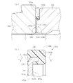
図9(a)に、特許文献1の車軸用軸受装置の部分拡大図を示し、図9(b)に、同車軸用軸受装置を構成するスペーサ部材の部分拡大図を示す。図9(a)(b)に示すように、特許文献1のスペーサ部材103は、銅合金等の軟質金属で形成された環状の芯金104と、芯金104の外周縁部に設けられた環状の弾性シール材105とを備える。芯金104は、互いに対向する内輪101の端面101a及び後蓋102の内径側端面102aにそれぞれ当接する第1及び第2の当接面104a,104bを有し、内輪101と後蓋102の直接接触に起因したフレッティング摩耗粉の発生を抑制する。また、弾性シール材105は、芯金104の軸方向両側にそれぞれ設けられた第1及び第2シール部105A,105Bを有し、第1シール部105A及び第2シール部105Bの端面は、内輪101の端面101a及び後蓋102の外径側端面102bにそれぞれ密着して(圧接されて)内輪101と後蓋102の間の開口部を密封する。これにより、仮にフレッティング摩耗粉が発生した場合でも、この摩耗粉が転がり軸受の内部空間に侵入するのを可及的に防止することができる。
FIG. 9A shows a partially enlarged view of the axle bearing device of Patent Document 1, and FIG. 9B shows a partially enlarged view of the spacer member constituting the axle bearing device. As shown in FIGS. 9A and 9B, the
鉄道車両の運転中、車軸はラジアル荷重を受けて撓みながら回転するため、スペーサ部材103には、その軸方向両側に配置された内輪101及び後蓋102から、図9(b)中に白抜き矢印で示すような軸方向の圧縮荷重(変動圧縮荷重)が繰り返し入力される。このような圧縮荷重がスペーサ部材103に入力された場合、弾性シール材105は、芯金104よりも低剛性の材料で形成されているため、芯金104よりも軸方向に大きく圧縮変形する。このため、スペーサ部材103に軸方向の圧縮荷重が繰り返し入力されると、弾性シール材105のうち特に軸方向の肉厚が薄い部分(第1シール部105Aの内径側領域106)は、内輪101と芯金104とで繰り返し挟まれることによって過大圧縮ひずみが生じ、この過大圧縮ひずみが生じた部分を起点として弾性シール材105が破損等し易くなる。弾性シール材105が破損した場合、弾性シール材105のシール機能(フレッティング摩耗粉の流出防止機能)が損なわれ、その結果、車軸用軸受装置の短寿命化を招来する。
Since the axle rotates while flexing under a radial load during operation of the railroad vehicle, the
上記の問題は、以上で説明したように、弾性シール材105の第1シール部105Aを内輪101に隣接配置した場合のみならず、図9(b)に示す弾性シール材105の左右を反転させ、第1シール部105Aを後蓋102に隣接配置した場合にも同様に生じ得る。
As described above, the above problem is not only when the
以上の実情に鑑み、本発明の課題は、シール機能(フレッティング摩耗粉の流出防止機能)を長期間に亘って安定的に発揮することができるシール付スペーサ部材を提供し、これにより、鉄道車両の車軸用軸受装置の耐久性及び信頼性向上に寄与することにある。 In view of the above circumstances, an object of the present invention is to provide a spacer member with a seal capable of stably exerting a sealing function (a function of preventing the outflow of fretting wear debris) for a long period of time, thereby providing a railway. The purpose is to contribute to improving the durability and reliability of the bearing device for the axle of a vehicle.
上記の課題を解決するために創案された本願の第1発明は、鉄道車両の車軸を回転自在に支持する転がり軸受と、転がり軸受の軸方向外側に配置される筒状部材とを備えた車軸用軸受装置のうち、転がり軸受の内輪と筒状部材の間に配置される環状のスペーサ部材であって、互いに対向する内輪及び筒状部材の端面にそれぞれ当接する第1及び第2当接面を有する環状の芯金と、芯金の外周縁部に設けられ、内輪と筒状部材の間の開口部を密封する環状の弾性シール材とを備え、芯金の軸方向両側にそれぞれ設けられた弾性シール材を構成する第1及び第2シール部のうち、第1シール部が内輪の前記端面に圧接される圧接面を有するスペーサ部材において、芯金が、第1当接面よりも圧接面との軸方向の離間距離が大きい環状の段差面を有し、段差面の少なくとも一部が第1シール部で被覆されていることを特徴する。なお、ここでいう「内輪の前記端面」とは、詳細には、芯金の第1当接面が当接する内輪の端面、である。 The first invention of the present application, which was devised to solve the above problems, is an axle provided with a rolling bearing that rotatably supports the axle of a railroad vehicle and a tubular member arranged outside the rolling bearing in the axial direction. Of the bearing devices for use, the first and second contact surfaces which are annular spacer members arranged between the inner ring of the rolling bearing and the tubular member and which come into contact with the end faces of the inner ring and the tubular member which face each other, respectively. It is provided with an annular core metal having an annular shape and an annular elastic sealing material provided on the outer peripheral edge portion of the core metal and sealing an opening between an inner ring and a tubular member, and provided on both sides of the core metal in the axial direction. Of the first and second sealing portions constituting the elastic sealing material, in the spacer member having a pressure contact surface in which the first sealing portion is pressed against the end surface of the inner ring, the core metal is pressed against the first contact surface. It is characterized by having an annular stepped surface having a large axial separation distance from the surface, and at least a part of the stepped surface is covered with a first seal portion. The "end surface of the inner ring" referred to here is, in detail, the end surface of the inner ring with which the first contact surface of the core metal contacts.
上記の構成によれば、スペーサ部材を含む車軸用軸受装置を車軸の外周に取り付けた状態において、内輪とスペーサ部材の芯金との間に介在する弾性シール材の第1シール部の軸方向寸法(第1シール部の軸方向の肉厚。以下同様。)を、図9(a)(b)に示す構成に比べて増すことができる。そのため、スペーサ部材に軸方向の圧縮荷重が繰り返し入力されても、弾性シール材(特に第1シール部)に圧縮ひずみが生じ難くなり、弾性シール材のシール機能を長期間に亘って安定的に維持することができる。 According to the above configuration, when the axle bearing device including the spacer member is attached to the outer periphery of the axle, the axial dimension of the first seal portion of the elastic sealing material interposed between the inner ring and the core metal of the spacer member. (Thickness of the first seal portion in the axial direction. The same shall apply hereinafter) can be increased as compared with the configuration shown in FIGS. 9A and 9B. Therefore, even if a compressive load in the axial direction is repeatedly input to the spacer member, compressive strain is less likely to occur in the elastic sealing material (particularly the first sealing portion), and the sealing function of the elastic sealing material is stable over a long period of time. Can be maintained.
弾性シール材の第1シール部に圧縮ひずみが生じる可能性を効果的に低減する上では、内輪の端面に対する第1シール部の潰し代(締め代)をa、第1シール部の軸方向寸法をbとしたとき、a/b<0.5の関係式を満たすようにするのが好ましく、a/b<0.2の関係式を満たすようにするのが一層好ましい。 In order to effectively reduce the possibility of compressive strain occurring in the first seal portion of the elastic seal material, the crushing allowance (tightening allowance) of the first seal portion with respect to the end face of the inner ring is a, and the axial dimension of the first seal portion. When b is, it is preferable that the relational expression of a / b <0.5 is satisfied, and it is more preferable that the relational expression of a / b <0.2 is satisfied.
また、内輪の端面と第1シール部の圧接面とを全周に亘って適切に密着させるため、第1シール部の軸方向寸法をb、第1シール部の内径寸法(内径面の直径寸法)をφd、芯金の外径寸法(最大外径寸法)をφeとしたとき、φe−φd>bの関係式を満たすようにするのが好ましく、φe−φd>2bの関係式を満たすようにするのが一層好ましい。 Further, in order to appropriately bring the end surface of the inner ring and the pressure contact surface of the first seal portion into close contact with each other over the entire circumference, the axial dimension of the first seal portion is b, and the inner diameter dimension of the first seal portion (diameter dimension of the inner diameter surface). ) Is φd and the outer diameter dimension (maximum outer diameter dimension) of the core metal is φe, it is preferable that the relational expression of φe−φd> b is satisfied, and the relational expression of φe−φd> 2b is satisfied. Is more preferable.
上記の第1発明は、第2シール部が、筒状部材に設けられた軸方向に延びる円筒状外周面に圧入される円筒状内周面を有する場合に好ましく適用することができる。 The above-mentioned first invention can be preferably applied when the second seal portion has a cylindrical inner peripheral surface that is press-fitted into a cylindrical outer peripheral surface extending in the axial direction provided in the tubular member.
また、上記の課題を解決するために創案された本願の第2発明は、鉄道車両の車軸を回転自在に支持する転がり軸受と、転がり軸受の軸方向外側に配置される筒状部材とを備えた車軸用軸受装置のうち、転がり軸受の内輪と筒状部材の間に配置される環状のスペーサ部材であって、互いに対向する筒状部材及び内輪の端面にそれぞれ当接する第1及び第2当接面を有する環状の芯金と、芯金の外周縁部に設けられ、筒状部材と内輪の間の開口部を密封する環状の弾性シール材とを備え、芯金の軸方向両側にそれぞれ設けられた弾性シール材を構成する第1及び第2シール部のうち、第1シール部が筒状部材の前記端面に圧接される圧接面を有するスペーサ部材において、芯金が、第1当接面よりも圧接面との軸方向の離間距離が大きい環状の段差面を有し、段差面の少なくとも一部が第1シール部で被覆されていることを特徴とする。なお、ここでいう「筒状部材の前記端面」とは、詳細には、芯金の第1当接面が当接する筒状部材の端面、である。 Further, the second invention of the present application, which was devised to solve the above problems, includes a rolling bearing that rotatably supports the axle of a railroad vehicle, and a tubular member arranged outside the rolling bearing in the axial direction. Among the axle bearing devices, the first and second annular spacer members arranged between the inner ring and the tubular member of the rolling bearing, which are in contact with the end faces of the tubular member and the inner ring facing each other, respectively. An annular core metal having a contact surface and an annular elastic sealing material provided on the outer peripheral edge of the core metal and sealing an opening between a tubular member and an inner ring are provided, and both sides of the core metal in the axial direction are provided. Of the first and second sealing portions constituting the provided elastic sealing material, in the spacer member having a pressure contact surface in which the first sealing portion is pressed against the end surface of the tubular member, the core metal comes into contact with the first contact. It is characterized by having an annular stepped surface having a larger axial separation distance from the pressure contact surface than the surface, and at least a part of the stepped surface is covered with the first seal portion. The "end surface of the tubular member" referred to here is, in detail, an end surface of the tubular member with which the first contact surface of the core metal comes into contact.
このような構成によれば、第1発明と同様の作用効果を享受することができる。 According to such a configuration, the same effects as those of the first invention can be enjoyed.
第2発明の構成においても、筒状部材の端面に対する第1シール部の潰し代(締め代)をa、第1シール部の軸方向寸法をbとしたとき、a/b<0.5の関係式を満たすようにするのが好ましく、a/b<0.2の関係式を満たすようにするのが一層好ましい。また、第1シール部の軸方向寸法をb、第1シール部の内径寸法をφd、芯金の外径寸法をφeとしたとき、φe−φd>bの関係式を満たすようにするのが好ましく、φe−φd>2bの関係式を満たすようにするのが一層好ましい。 Also in the configuration of the second invention, when the crushing allowance (tightening allowance) of the first seal portion with respect to the end face of the tubular member is a and the axial dimension of the first seal portion is b, a / b <0.5. It is preferable to satisfy the relational expression, and it is more preferable to satisfy the relational expression of a / b <0.2. Further, when the axial dimension of the first seal portion is b, the inner diameter dimension of the first seal portion is φd, and the outer diameter dimension of the core metal is φe, the relational expression of φe−φd> b is satisfied. It is preferable that the relational expression of φe−φd> 2b is satisfied.
第2発明は、第2シール部が、内輪に設けられた軸方向に延びる円筒状外周面に圧入される円筒状内周面を有する場合に好ましく適用することができる。 The second invention can be preferably applied when the second seal portion has a cylindrical inner peripheral surface that is press-fitted into a cylindrical outer peripheral surface that extends in the axial direction provided on the inner ring.
以上の構成において、第1シール部は、段差面の外径側の一部領域を被覆するように設けても良いし(例えば、図2)、段差面の全域を被覆するように設けても良い(例えば、図5)。 In the above configuration, the first seal portion may be provided so as to cover a part of the outer diameter side of the stepped surface (for example, FIG. 2), or may be provided so as to cover the entire area of the stepped surface. Good (eg, Figure 5).
また、以上の構成において、第1シール部の圧接面の全域は、芯金よりも外径側に設けることができる(例えば、図5)。このようにすれば、第1シール部に圧縮ひずみが生じる可能性を一層効果的に低減することができる。 Further, in the above configuration, the entire area of the pressure contact surface of the first seal portion can be provided on the outer diameter side of the core metal (for example, FIG. 5). In this way, the possibility of compressive strain occurring in the first seal portion can be further effectively reduced.
芯金には、潤滑剤を保持可能な潤滑剤保持部を設けることができる。潤滑剤保持部を設け、この潤滑剤保持部に潤滑剤を保持させておけば、内輪と筒状部材間の潤滑性が向上する他、芯金自体の摩耗も抑制することができるので、摩耗粉の発生を抑制する上で有利となる。 The core metal may be provided with a lubricant holding portion capable of holding the lubricant. If a lubricant holding portion is provided and the lubricant is held in the lubricant holding portion, the lubricity between the inner ring and the tubular member can be improved, and the wear of the core metal itself can be suppressed. It is advantageous in suppressing the generation of powder.
鉄道車両の車軸を回転可能に支持する転がり軸受と、転がり軸受の軸方向外側に配置された筒状部材とを備え、転がり軸受の内輪と筒状部材の間に本発明に係るスペーサ部材を配置してなる車軸用軸受装置は、本発明に係るスペーサ部材が前述したような作用効果を奏し得ることから、耐久性及び信頼性に富むものとなる。なお、転がり軸受は、ラジアル荷重およびアキシャル荷重の双方を支持することができ、かつこれらの荷重負荷能力に優れた複列円すいころ軸受とするのが好ましい。 A rolling bearing that rotatably supports the axle of a railroad vehicle and a tubular member arranged on the outer side in the axial direction of the rolling bearing are provided, and a spacer member according to the present invention is arranged between the inner ring of the rolling bearing and the tubular member. Since the spacer member according to the present invention can exert the above-mentioned action and effect, the bearing device for an axle is highly durable and reliable. The rolling bearing is preferably a double-row tapered roller bearing that can support both a radial load and an axial load and has excellent load-bearing capacity.
以上より、本発明によれば、弾性シール材に圧縮ひずみが生じ難くなり、弾性シール材の耐久性を高めることができるので、フレッティング摩耗粉の流出防止機能(シール機能)に優れたスペーサ部材(弾性シール付のスペーサ部材)を提供することができる。これにより、耐久性及び信頼性に富む車軸用軸受装置を実現することができる。 From the above, according to the present invention, the elastic sealing material is less likely to undergo compressive strain, and the durability of the elastic sealing material can be improved. Therefore, the spacer member having an excellent function of preventing the outflow of fretting wear powder (sealing function). (Spacer member with elastic seal) can be provided. As a result, it is possible to realize an axle bearing device having high durability and reliability.
以下、本発明の実施の形態を図面に基づいて説明する。 Hereinafter, embodiments of the present invention will be described with reference to the drawings.
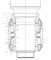
図1に、本発明の実施形態に係る車軸用軸受装置1の全体構造を示す。同図に示す車軸用軸受装置1は、鉄道車両の車軸2を回転自在に支持する転がり軸受3と、一対のシール装置10,10と、転がり軸受3の軸方向両側にそれぞれ配置された第1及び第2の筒状部材としての油切り8及び後蓋9と、転がり軸受3と後蓋9の間に配置された環状のスペーサ部材20とを備える。
FIG. 1 shows the overall structure of the axle bearing device 1 according to the embodiment of the present invention. The axle bearing device 1 shown in the figure includes a rolling
転がり軸受3は、複列の内側軌道面4a,4aを有し、車軸2の外周に装着された内輪4と、複列の外側軌道面5a,5aを有し、図示外の軸箱の内周に装着された外輪5と、対をなす軌道面4a,5a間に配置された複数の円すいころ6と、円すいころ6の各列を周方向所定間隔で保持する一対の保持器7,7とを備えた、いわゆる複列円すいころ軸受である。図示例では、転がり軸受3の軸方向中央部で突き合わされた一対の分割内輪で内輪4を構成しているが、内輪4として、一対の分割内輪の間に間座を介在させたものや、単一部材で構成されたものを用いることもできる。
The rolling
転がり軸受3の内部空間にはグリース等の潤滑剤が充填されており、該潤滑剤の外部漏洩及び軸受内部空間への異物侵入は、一対のシール装置10,10によって可及的に防止される。各シール装置10は、シール部材11と、外径側の端部が外輪5に固定され、内径側の端部が筒状部材に近接配置された段付き円筒状のシールカバー12とを備え、シール部材11はシールカバー12の内径面に取り付け固定される。シール部材11は、いわゆる接触タイプ又は非接触タイプの何れでも構わない。
The internal space of the rolling
油切り8は、車軸2の先端に締結される図示外のナットにより車軸2に固定され、転がり軸受3の内輪4と軸方向で係合している。後蓋9は、車軸2に設けた肩面2bと軸方向で係合することによって車軸2に固定され、スペーサ部材20を介して転がり軸受3の内輪4と軸方向で係合している。このような構成から、車軸2に対する転がり軸受3の軸方向の相対移動が規制され、転がり軸受3の軸方向の位置決めがなされる。
The oil drain 8 is fixed to the
図3にも示すように、本実施形態の転がり軸受3において、スペーサ部材20に隣接する内輪4の端面Mは、軸方向と直交する方向の平坦面に形成されている。また、スペーサ部材20に隣接する後蓋9の端面は、軸方向と直交する方向の平坦面に形成された内径側端面N1と、内径側端面N1よりも車軸2の軸方向中央側にシフトした位置に設けられ、軸方向と直交する方向の平坦面に形成された外径側端面N2とに区分され、両端面N1,N2は、軸方向に延びる円筒状外周面N3を介して連続している。
As shown in FIG. 3, in the rolling
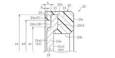
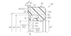
図2に、単体(取付け前)のスペーサ部材20の部分拡大図を示す。スペーサ部材20は、環状の芯金21と、芯金21の外周縁部に設けられた環状の弾性シール材22とからなる。
FIG. 2 shows a partially enlarged view of the
芯金21は、内径側環状部21aと、内径側環状部21aよりも車軸2の軸方向中央側に位置する外径側環状部21bとを一体に有する段付き円環状をなし、スペーサ部材20を含む車軸用軸受装置1を車軸2に取り付けた状態(図1及び図3参照)では、内径側環状部21aが内輪4と後蓋9とで軸方向両側から挟持される。従って、内径側環状部21aの一端面21a1及び他端面21a2は、それぞれ、本願の第1発明でいう第1当接面A1及び第2当接面A2を構成する。また、外径側環状部21bが上記態様で設けられていることにより、外径側環状部21bの一端面21b1は、第1当接面A1としての内径側環状部21aの一端面21a1よりも弾性シール材22の第1シール部23の圧接面C(詳細は後述する)との軸方向の離間距離が大きい。従って、外径側環状部21bの一端面21b1が本願の第1発明でいう段差面Bを構成する。
The
以上の構成を有する芯金21は、内輪4及び後蓋9よりも軟質の金属材料(例えば銅合金)で形成された薄板にプレス加工を施すことによって所定形状に成形された、いわゆるプレス成形品とされる。
The
弾性シール材22は、芯金21の軸方向両側にそれぞれ設けられた第1及び第2シール部23,24と、芯金21の外径側に設けられ、両シール部23,24を接続する接続部25とを一体に有する。第1シール部23は、芯金21の外径側環状部21bの一端面21b1(段差面B)のうち、外径側の一部領域を被覆するように設けられ、第2シール部24は、芯金21の外径側環状部21bの他端面21b2全域を被覆するように設けられている。第1シール部23の端面23aは、芯金21の内径側環状部21aの一端面21a1(第1当接面A1)よりも車軸2の自由端側に位置しており、スペーサ部材20を車軸2に取り付けた状態(図3参照)では、芯金21の第1当接面A1が当接する内輪4の端面Mの外径側領域に対して圧接される。従って、第1シール部23の端面23aが本願の第1発明でいう圧接面Cを構成する。
The
以上の構成を有する弾性シール材22は、例えば、ニトリルゴム、アクリルゴムおよびフッ素ゴムの群から選択される何れか一種を主成分とするゴム材料で形成され、本実施形態では、芯金21をインサート部品とした加硫成形によって芯金21と一体成形される。
The
以上の構成を有するスペーサ部材20は、図3に拡大して示すように、円筒面状に形成された弾性シール材22の第2シール部24の内周面(円筒状内周面)24bを後蓋9の円筒状外周面N3に圧入することによって車軸2の外周に取り付けられる。そして、車軸用軸受装置1を車軸2に取り付けた状態では、芯金21の内径側環状部21aの一端面21a1(第1当接面A1)が内輪4の端面M(の内径側領域)に当接すると共に、芯金21の内径側環状部21aの他端面21a2(第2当接面A2)が後蓋9の内径側端面N1に当接する。これにより、車軸2がラジアル荷重を受けて撓みながら回転する状況下においても、内輪4と後蓋9の直接接触が回避されるため、両者の直接接触が繰り返されることに由来するフレッティング摩耗粉の発生が可及的に防止される。
As shown in an enlarged view in FIG. 3, the
また、車軸用軸受装置1を車軸2に取り付けた状態では、第1シール部23の端面23aが内輪4の端面M(の外径側領域)に、また、第2シール部24の端面24aが後蓋9の外径側端面N2に対してそれぞれ圧接されるようにして、弾性シール材22が軸方向に圧縮変形した状態で内輪4と後蓋9の間に介在する。これにより、内輪4と後蓋9の間の開口部が密封されるため、仮に内輪4と芯金21の接触部や、後蓋9と芯金21の接触部で摩耗粉が発生した場合でも、その摩耗粉が、内輪4の外径側に流出して転がり軸受3の内部空間に侵入する可能性が効果的に低減される。
Further, in a state where the axle bearing device 1 is attached to the
本実施形態において、スペーサ部材20の芯金21は、内輪4の端面Mに当接する第1当接面A1よりも、圧接面Cとの軸方向の離間距離が大きい環状の段差面Bを有し、段差面Bの少なくとも一部が弾性シール材22を構成する第1シール部23で被覆されている。このような構成によれば、内輪4とスペーサ部材20の芯金21との間に介在する弾性シール材22の第1シール部23の軸方向寸法を、図9(b)に示す従来構成に比べて増すことができる。そのため、車軸2の回転に伴ってスペーサ部材20に軸方向の圧縮荷重が繰り返し入力されても、弾性シール材22の第1シール部23に圧縮ひずみが生じ難くなり、弾性シール材22のシール機能を長期間に亘って安定的に維持することができる。従って、長寿命で信頼性に富む車軸用軸受装置1を実現することができる。
In the present embodiment, the
なお、シール機能を担保する上では、内輪4の端面Mに対する弾性シール材22の第1シール部23の潰し代(締め代)a、すなわち、図2中に示す軸方向寸法a(スペーサ部材20単体の状態における、芯金21の第1当接面A1と弾性シール材22の圧接面Cの軸方向離間距離)は0.05mm以上(a≧0.05mm)とするのが好ましい。
In order to ensure the sealing function, the crushing allowance (tightening allowance) a of the
また、弾性シール材22の第1シール部23に圧縮ひずみが生じる可能性を効果的に低減する上では、内輪4の端面Mに対する弾性シール材22の潰し代aと、第1シール部23の軸方向寸法b(図2参照)との間に、a/b<0.5の関係式が成立するように、より好ましくはa/b<0.2の関係式が成立するように、段差面Bの軸方向位置を設定する。
Further, in order to effectively reduce the possibility of compression strain occurring in the
また、本実施形態では、弾性シール材22が、芯金21をインサート部品とした加硫成形によって芯金21と一体に型成形される。この場合、弾性シール材22の成形過程において、シール材成形用のゴム材料が芯金21の第1当接面A1に流出して硬化すると、図9(a)(b)を参照して説明した従来技術と同様の問題が生じるおそれもある。
Further, in the present embodiment, the
そのため、本実施形態では、弾性シール材22の第1シール部23を、芯金21の段差面Bのうち、外径側の一部領域のみを被覆するように設けた。このような形状を有する弾性シール材22を確実に成形可能とするため、芯金21の内径側環状部21aの外径寸法φc(図2参照)、および第1シール部23の内径寸法φd(図2参照)の値は、(φd−φc)/2>0.5mmの関係式が成立するように設定するのが好ましく、(φd−φc)/2>0.8mmの関係式が成立するように設定するのが一層好ましい。
Therefore, in the present embodiment, the
さらに、内輪4の端面Mと弾性シール材22の第1シール部23の端面23a(圧接面C)とを全周に亘って適切に密着させるため、芯金21の外径寸法をφe(図2参照)としたとき、第1シール部23の軸方向寸法bおよび内径寸法φdとの間に、φe−φd>bの関係式、より好ましくはφe−φd>2bの関係式が成立するように、各部の寸法を設定する。
Further, in order to appropriately bring the end surface M of the
以上で説明したスペーサ部材20を構成する芯金21のうち、内輪4の端面M及び後蓋9の内径側端面N1とそれぞれ当接する第1及び第2当接面A1,A2には、グリース等の潤滑剤を保持可能な潤滑剤保持部を設けることができる。図4(a)及び図4(b)はその具体例であり、図4(a)では、両当接面A1,A2に設けた溝部28で潤滑剤保持部を構成し、図4(b)では、両当接面A1,A2に設けた凹部(ディンプル)29で潤滑剤保持部を構成している。潤滑剤保持部は、これ以外にも、例えば両当接面A1,A2に開口する貫通穴で構成することも可能である。
Of the
上記のような潤滑剤保持部を設け、この潤滑剤保持部に適宜の潤滑剤(例えば、潤滑油)を保持させておけば、内輪4と芯金21の間及び後蓋9と芯金21の間の潤滑性を高めることができるので、フレッティング摩耗粉の発生を防止する上で有利となる。上述した潤滑剤保持部は、芯金21を所定形状に型成形(プレス成形)するのと同時に型成形することができ、また、後述する他の実施形態に係るスペーサ部材20においても採用することができる。
If the above-mentioned lubricant holding portion is provided and an appropriate lubricant (for example, lubricating oil) is held in the lubricant holding portion, the space between the
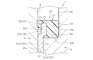
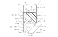
図5に、本願の第1発明の第2実施形態に係るスペーサ部材20の部分拡大図を示し、図6に、このスペーサ部材20を構成部品とする車軸用軸受装置1の部分拡大図を示す。図5及び図6に示すように、この実施形態では、スペーサ部材20を構成する芯金21及び弾性シール材22の形状が、図2等を参照して説明した第1実施形態のスペーサ部材20とは異なる。具体的に説明すると、この実施形態では、芯金21が、環状部(内径側環状部)21aと、内径側環状部21aの外径端部から軸方向に延びた筒状部21cとからなり、弾性シール材22は、芯金21の筒状部21c全体を被覆するように芯金21と一体的に設けられている。
FIG. 5 shows a partially enlarged view of the
この実施形態においても、スペーサ部材20の芯金21は、第1当接面A1(内径側環状部21aの一端面21a1)よりも圧接面Cとの軸方向の離間距離が大きい段差面Bを有し、段差面Bの少なくとも一部(本実施形態では段差面Bの全域)が弾性シール材22の第1シール部23で被覆されている。従って、図6に示す、車軸用軸受装置1を車軸2に取り付けた状態において、内輪4の端面Mと芯金21との間に介在する弾性シール材22の第1シール部23の軸方向寸法を、図9(a)(b)に示す従来構成よりも増すことができる。これにより、第1シール部23に圧縮ひずみが生じ難くなり、弾性シール材22のシール機能を長期間に亘って安定的に維持することができる。なお、本実施形態では、芯金21の内径側環状部21aの一端面21a1の外径端部を肉取りすることで段差面Bを形成している。
Also in this embodiment, the
また、本実施形態のスペーサ部材20において、内輪4の端面Mに対して圧接される弾性シール材22の第1シール部23の端面23a(圧接面C)は、その全域が芯金21の外径側に設けられている。すなわち、図5に示すように、第1シール部23のうち端面が圧接面Cとして機能する突出部の内径寸法をφd’とし、芯金21の外径寸法をφe’としたとき、φd’>φe’の関係式が成立する。この場合、車軸2の回転に伴って、スペーサ部材20に対して軸方向の圧縮荷重が繰り返し入力されても、第1シール部23には、内輪4と芯金21との間で挟み潰される部分が実質的になくなる。このため、第1シール部23に圧縮ひずみが生じる可能性は一層効果的に減じられる。
Further, in the
この実施形態においても、弾性シール材22のシール機能を担保する上では、内輪4の端面Mに対する第1シール部23の潰し代(締め代)a’、すなわち図5中に示す軸方向寸法a’は0.05mm以上(a’≧0.05mm)とするのが好ましい。
Also in this embodiment, in order to ensure the sealing function of the
また、第1シール部23に圧縮ひずみが生じる可能性を効果的に低減する上では、内輪4の端面Mに対する弾性シール材22(第1シール部23)の潰し代a’と、第1シール部23の軸方向寸法b’(図5参照)との間に、a’/b’<0.5の関係式が成立するようにするのが好ましく、a’/b’<0.2の関係式が成立するようにするのが一層好ましい。
Further, in order to effectively reduce the possibility of compressive strain occurring in the
この実施形態の弾性シール材22も、芯金21をインサート部品とした加硫成形により、芯金21と一体に型成形される。このシール材22の成形時に、シール材22成形用のゴム材料が芯金21の第1当接面A1及び第2当接面A2に流出しないようにするため、第1シール部23の内径寸法をφc’とし、第2シール部24の円筒状内周面24bの内径寸法をφf’としたとき(図5参照)、φc’=φf’に設定するのが好ましい。
The
以下、本願の第2発明の実施形態に係る車軸用軸受装置1を説明する。簡単に説明すると、第2発明の実施形態に係る車軸用軸受装置1は、スペーサ部材20を介して対向する内輪4の端面と筒状部材としての後蓋9の端面の形状が、第1発明の実施形態に係る車軸用軸受装置1とは反対となっている。
Hereinafter, the axle bearing device 1 according to the second embodiment of the present application will be described. Briefly, in the axle bearing device 1 according to the embodiment of the second invention, the shape of the end face of the
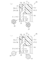
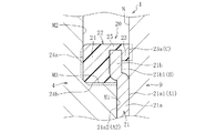
すなわち、第2発明の第1及び第2実施形態に係る車軸用軸受装置1では、図7及び図8にそれぞれ示すように、スペーサ部材20に隣接する後蓋9の端面Nが軸方向と直交する方向の平坦面に形成される一方で、スペーサ部材20に隣接する転がり軸受3の内輪4の端面が、軸方向と直交する方向の平坦面に形成された内径側端面M1と、内径側端面M1よりも車軸2の自由端側にシフトした位置に設けられ、軸方向と直交する方向の平坦面に形成された外径側端面M2とに区分される。内輪4の内径側端面M1と外径側端面M2とは、軸方向に延びた円筒状外周面M3を介して連続しており、この円筒状外周面M3に対してスペーサ部材20の弾性シール材22を構成する第2シール部24の円筒状内周面24bが圧入される。
That is, in the axle bearing device 1 according to the first and second embodiments of the second invention, as shown in FIGS. 7 and 8, the end surface N of the
図7に示す第2発明の第1実施形態に係る車軸用軸受装置1では、第1発明の第1実施形態に係る車軸用軸受装置1を構成するスペーサ部材20(図2参照)が、左右を反転させた状態で取り付けられる。このため、この車軸用軸受装置1を車軸2に取り付けた状態において、スペーサ部材20を構成する芯金21は、その内径側環状部21aの一端面21a1(第1当接面A1)及び他端面21a2(第2当接面A2)が後蓋9の端面N(の内径側領域)及び内輪4の内径側端面M1にそれぞれ当接し、スペーサ部材20を構成する弾性シール材22は、第1シール部23の端面23a(圧接面C)及び第2シール部24の端面24aが後蓋9の端面N(の外径側領域)及び内輪4の外径側端面M2に対してそれぞれ圧接されて、内輪4と後蓋9の間の開口部を密封する。
In the axle bearing device 1 according to the first embodiment of the second invention shown in FIG. 7, the spacer members 20 (see FIG. 2) constituting the axle bearing device 1 according to the first embodiment of the first invention are left and right. Can be installed in an inverted state. Therefore, in a state where the axle bearing device 1 is attached to the
この実施形態において、スペーサ部材20の芯金21は、第1当接面A1よりも圧接面Cとの軸方向の離間距離が大きい環状の段差面Bを有し、段差面Bの外径側領域が弾性シール材22の第1シール部23で被覆されている。従って、図3に示す第1発明の第1実施形態に係る車軸用軸受装置1と同様に、長寿命で信頼性に富む車軸用軸受装置1を実現することができる。なお、この実施形態のスペーサ部材20のその他の特徴的構成は、図2に示すスペーサ部材20に準ずるので詳細説明を省略する。
In this embodiment, the
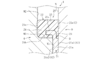
図8に示す第2発明の第2実施形態に係る車軸用軸受装置1では、図5に示すスペーサ部材20が左右を反転させた状態で取り付けられる。このため、この車軸用軸受装置1を車軸2に取り付けた状態においても、スペーサ部材20を構成する芯金21は、その内径側環状部21aの一端面21a1(第1当接面A1)及び他端面21a2(第2当接面A2)が後蓋9の端面N(の内径側領域)及び内輪4の内径側端面M1にそれぞれ当接し、スペーサ部材20を構成する弾性シール材22は、第1シール部23の端面23a(圧接面C)及び第シール部24の端面24aが後蓋9の端面N(の外径側領域)及び内輪4の外径側端面M2に対してそれぞれ圧接されて、内輪4と後蓋9の間の開口部を密封する。
In the axle bearing device 1 according to the second embodiment of the second invention shown in FIG. 8, the
この実施形態においても、スペーサ部材20の芯金21は、第1当接面A1よりも圧接面Cとの軸方向の離間距離が大きい環状の段差面Bを有し、段差面Bの全域が弾性シール材22の第1シール部23で被覆されている。従って、図6に示す第1発明の第2実施形態に係る車軸用軸受装置1と同様に、長寿命で信頼性に富む車軸用軸受装置1を実現することができる。なお、この実施形態のスペーサ部材20のその他の特徴的構成は、図5に示すスペーサ部材20に準ずるので詳細説明を省略する。
Also in this embodiment, the
以上では、本発明に係るスペーサ部材20を、転がり軸受3の内輪4と第2の筒状部材としての後蓋9との間にのみ配置した車軸用軸受装置1を説明したが、本発明に係るスペーサ部材20は、内輪4と第1の筒状部材としての油切り8との間に配置することももちろん可能である。すなわち、本発明は、内輪4と油切り8との間にのみスペーサ部材20が配置される車軸用軸受装置1や、内輪4と油切り8との間、および内輪4と後蓋9との間のそれぞれにスペーサ部材20が配置される車軸用軸受装置1にも適用することができる。
In the above, the axle bearing device 1 in which the
本発明は前述した実施形態に何ら限定されるものではなく、本発明の要旨を逸脱しない範囲内において、さらに種々の形態で実施し得ることは勿論のことである。本発明の範囲は、特許請求の範囲によって示され、さらに特許請求の範囲に記載の均等の意味、および範囲内のすべての変更を含む。 The present invention is not limited to the above-described embodiments, and it goes without saying that the present invention can be further implemented in various forms without departing from the gist of the present invention. The scope of the present invention is indicated by the scope of claims, and further includes the equal meaning described in the scope of claims, and all modifications within the scope.
1 車軸用軸受装置
2 車軸
3 転がり軸受
4 内輪
5 外輪
8 油切り(第1の筒状部材)
9 後蓋(第2の筒状部材)
10 シール装置
20 スペーサ部材
21 芯金
22 弾性シール材
23 第1シール部
24 第2シール部
28 溝部(潤滑剤保持部)
28 凹部(潤滑剤保持部)
A1 第1当接面
A2 第2当接面
B 段差面
C 圧接面
1
9 Rear lid (second tubular member)
10
28 Recess (lubricant holding part)
A1 1st contact surface A2 2nd contact surface B Step surface C Pressure contact surface
Claims (13)
互いに対向する前記内輪及び前記筒状部材の端面にそれぞれ当接する第1及び第2当接面を有する環状の芯金と、芯金の外周縁部に設けられ、前記内輪と前記筒状部材の間の開口部を密封する環状の弾性シール材とを備え、前記芯金の軸方向両側にそれぞれ設けられた弾性シール材を構成する第1及び第2シール部のうち、第1シール部が内輪の前記端面に圧接される圧接面を有するスペーサ部材において、
前記芯金が、前記第1当接面よりも前記圧接面との軸方向の離間距離が大きい環状の段差面を有し、該段差面の少なくとも一部が前記第1シール部で被覆され、
前記圧接面の全域が前記芯金よりも外径側に設けられ、前記第1シール部が、前記内輪と前記芯金との間で挟み潰される部分を有していないことを特徴とするスペーサ部材。 A rolling bearing rotatably supporting an axle of a railway vehicle, of the axle bearing apparatus provided with a tubular member disposed axially outward of the rolling bearing, between the cylindrical member and the inner ring of the rolling bearing An annular spacer member to be arranged
An annular core metal having first and second abutment surfaces abut the respective end face of the inner ring and the tubular member facing each other, provided on the outer periphery of the metal core, said inner ring and said tubular member and an annular elastic sealing member for sealing the opening between, of the first and second seal portions constituting the elastic sealing member respectively provided on both sides in the axial direction of the metal core, the first sealing portion is the inner ring In the spacer member having a pressure contact surface to be pressure-welded to the end surface of
The core metal, having said distance is larger annular step surface in the axial direction of the first said pressing surface than the abutment surface, at least a portion of the stepped surface is covered with the first sealing portion,
A spacer characterized in that the entire area of the pressure contact surface is provided on the outer diameter side of the core metal, and the first seal portion does not have a portion to be sandwiched between the inner ring and the core metal. Element.
互いに対向する前記筒状部材及び前記内輪の端面にそれぞれ当接する第1及び第2当接面を有する環状の芯金と、芯金の外周縁部に設けられ、前記筒状部材と前記内輪の間の開口部を密封する環状の弾性シール材とを備え、前記芯金の軸方向両側にそれぞれ設けられた弾性シール材を構成する第1及び第2シール部のうち、第1シール部が筒状部材の前記端面に圧接される圧接面を有するスペーサ部材において、
前記芯金が、前記第1当接面よりも前記圧接面との軸方向の離間距離が大きい環状の段差面を有し、該段差面の少なくとも一部が前記第1シール部で被覆され、
前記圧接面の全域が前記芯金よりも外径側に設けられ、前記第1シール部が、前記筒状部材と前記芯金との間で挟み潰される部分を有していないことを特徴とするスペーサ部材。 A rolling bearing rotatably supporting an axle of a railway vehicle, of the axle bearing apparatus provided with a tubular member disposed axially outward of the rolling bearing, between the cylindrical member and the inner ring of the rolling bearing An annular spacer member to be arranged
An annular core metal having first and second abutment surfaces abut to each of the tubular member and the end face of the inner ring facing each other, provided on the outer periphery of the core, the inner ring of the tubular member and an annular elastic sealing member for sealing the opening between, of the first and second seal portions constituting the elastic sealing member respectively provided on both sides in the axial direction of the metal core, the first seal portion is cylindrical In a spacer member having a pressure contact surface that is pressure-welded to the end surface of the shaped member,
The core metal, having said distance is larger annular step surface in the axial direction of the first said pressing surface than the abutment surface, at least a portion of the stepped surface is covered with the first sealing portion,
The entire area of the pressure contact surface is provided on the outer diameter side of the core metal, and the first seal portion does not have a portion to be sandwiched between the tubular member and the core metal. Spacer member to be used.
前記第2当接面の全域が同一平面上に位置している請求項1〜10の何れか一項に記載のスペーサ部材。 The stepped surface is formed by partially thinning one end surface of the core metal constituting the first contact surface.
The spacer member according to any one of claims 1 to 10, wherein the entire area of the second contact surface is located on the same plane .
Priority Applications (3)
| Application Number | Priority Date | Filing Date | Title |
|---|---|---|---|
| JP2017001845A JP6794271B2 (en) | 2017-01-10 | 2017-01-10 | Spacer member and axle bearing device equipped with this |
| PCT/JP2017/044344 WO2018131359A1 (en) | 2017-01-10 | 2017-12-11 | Spacer member and axle bearing device provided therewith |
| CN201780082836.2A CN110192042B (en) | 2017-01-10 | 2017-12-11 | Spacer member and axle bearing device provided with same |
Applications Claiming Priority (1)
| Application Number | Priority Date | Filing Date | Title |
|---|---|---|---|
| JP2017001845A JP6794271B2 (en) | 2017-01-10 | 2017-01-10 | Spacer member and axle bearing device equipped with this |
Publications (2)
| Publication Number | Publication Date |
|---|---|
| JP2018112220A JP2018112220A (en) | 2018-07-19 |
| JP6794271B2 true JP6794271B2 (en) | 2020-12-02 |
Family
ID=62840555
Family Applications (1)
| Application Number | Title | Priority Date | Filing Date |
|---|---|---|---|
| JP2017001845A Active JP6794271B2 (en) | 2017-01-10 | 2017-01-10 | Spacer member and axle bearing device equipped with this |
Country Status (3)
| Country | Link |
|---|---|
| JP (1) | JP6794271B2 (en) |
| CN (1) | CN110192042B (en) |
| WO (1) | WO2018131359A1 (en) |
Families Citing this family (1)
| Publication number | Priority date | Publication date | Assignee | Title |
|---|---|---|---|---|
| CN110998769B (en) | 2017-07-21 | 2022-07-01 | 日本精工株式会社 | Dye-sensitized photoelectric conversion element |
Family Cites Families (4)
| Publication number | Priority date | Publication date | Assignee | Title |
|---|---|---|---|---|
| JP4060232B2 (en) * | 2003-05-12 | 2008-03-12 | Ntn株式会社 | Railway vehicle bearing device |
| JP4593171B2 (en) * | 2004-05-24 | 2010-12-08 | Ntn株式会社 | Railway vehicle bearing device |
| CN201322044Y (en) * | 2009-03-10 | 2009-10-07 | 青岛四方车辆研究所有限公司 | High-occupancy railway wagon bearing |
| US8356941B2 (en) * | 2010-03-08 | 2013-01-22 | Amsted Rail Company, Inc. | Railway car bearing seal |
-
2017
- 2017-01-10 JP JP2017001845A patent/JP6794271B2/en active Active
- 2017-12-11 WO PCT/JP2017/044344 patent/WO2018131359A1/en not_active Ceased
- 2017-12-11 CN CN201780082836.2A patent/CN110192042B/en active Active
Also Published As
| Publication number | Publication date |
|---|---|
| CN110192042A (en) | 2019-08-30 |
| WO2018131359A1 (en) | 2018-07-19 |
| JP2018112220A (en) | 2018-07-19 |
| CN110192042B (en) | 2021-03-12 |
Similar Documents
| Publication | Publication Date | Title |
|---|---|---|
| JP2013194756A (en) | Sealing device, and rolling bearing device | |
| JP6214891B2 (en) | Bearing device with sealing device | |
| WO2017204058A1 (en) | Bearing sealing device | |
| JP6794271B2 (en) | Spacer member and axle bearing device equipped with this | |
| WO2016125516A1 (en) | Bearing device for railway vehicle | |
| CN111749982A (en) | Axle bearing device | |
| JP2018168986A (en) | Ball bearing | |
| JP2005226787A (en) | Sealing device for bearing | |
| JP4260935B2 (en) | Railway vehicle bearing device | |
| CN109661523A (en) | Axle bearing arrangement | |
| JP2015075218A (en) | Roller bearing with seal device | |
| JP3986775B2 (en) | Railway vehicle bearing unit | |
| JP2006017238A (en) | Rolling bearing | |
| JP2019082239A (en) | Wheel bearing device | |
| JP2019100505A (en) | Hub unit bearing and manufacturing method of hub unit bearing | |
| JP2017223283A (en) | Bearing device | |
| JP2010121725A (en) | Rolling bearing device | |
| JP2006002815A (en) | Bearing unit for rolling stock | |
| JP2021167647A (en) | Rolling bearing | |
| JP4748050B2 (en) | Sealed thrust ball bearing | |
| JP2001116055A (en) | Double row conical roller bearing | |
| JP6546034B2 (en) | Hub unit sealing device | |
| JP2010116107A (en) | Axle device for railway vehicle | |
| EP1975434B1 (en) | Rolling bearing device | |
| JP4905222B2 (en) | Rolling bearing device |
Legal Events
| Date | Code | Title | Description |
|---|---|---|---|
| A621 | Written request for application examination |
Free format text: JAPANESE INTERMEDIATE CODE: A621 Effective date: 20191226 |
|
| A131 | Notification of reasons for refusal |
Free format text: JAPANESE INTERMEDIATE CODE: A131 Effective date: 20200521 |
|
| A521 | Request for written amendment filed |
Free format text: JAPANESE INTERMEDIATE CODE: A523 Effective date: 20200703 |
|
| TRDD | Decision of grant or rejection written | ||
| A01 | Written decision to grant a patent or to grant a registration (utility model) |
Free format text: JAPANESE INTERMEDIATE CODE: A01 Effective date: 20201028 |
|
| A61 | First payment of annual fees (during grant procedure) |
Free format text: JAPANESE INTERMEDIATE CODE: A61 Effective date: 20201111 |
|
| R150 | Certificate of patent or registration of utility model |
Ref document number: 6794271 Country of ref document: JP Free format text: JAPANESE INTERMEDIATE CODE: R150 |
|
| R250 | Receipt of annual fees |
Free format text: JAPANESE INTERMEDIATE CODE: R250 |
|
| R250 | Receipt of annual fees |
Free format text: JAPANESE INTERMEDIATE CODE: R250 |
|
| R250 | Receipt of annual fees |
Free format text: JAPANESE INTERMEDIATE CODE: R250 |