JP6791932B2 - Holding structure of the device - Google Patents
Holding structure of the device Download PDFInfo
- Publication number
- JP6791932B2 JP6791932B2 JP2018209432A JP2018209432A JP6791932B2 JP 6791932 B2 JP6791932 B2 JP 6791932B2 JP 2018209432 A JP2018209432 A JP 2018209432A JP 2018209432 A JP2018209432 A JP 2018209432A JP 6791932 B2 JP6791932 B2 JP 6791932B2
- Authority
- JP
- Japan
- Prior art keywords
- main body
- bearing
- portions
- stand
- shaft portion
- Prior art date
- Legal status (The legal status is an assumption and is not a legal conclusion. Google has not performed a legal analysis and makes no representation as to the accuracy of the status listed.)
- Active
Links
Images


Description
本発明は、装置の姿勢を保持するための保持構造に関する。 The present invention relates to a holding structure for holding the posture of the device.
従来、表示装置を備えた略板状の情報処理装置の姿勢を、当該装置とは別のスタンドを用いて保持するものがある(例えば、特許文献1参照)。 Conventionally, there is a device that holds the posture of a substantially plate-shaped information processing device provided with a display device by using a stand different from the device (see, for example, Patent Document 1).
装置の姿勢を保持する構造としてユーザにとってより利便性のある構造が求められる。 As a structure for holding the posture of the device, a structure that is more convenient for the user is required.
それ故、本発明の目的は、装置の姿勢を保持することが可能な利便性ある保持構造を提供することである。 Therefore, an object of the present invention is to provide a convenient holding structure capable of holding the posture of the device.
上記の課題を解決すべく、本発明は、以下の構成を採用した。 In order to solve the above problems, the present invention has adopted the following configuration.
本発明の一例に係る保持構造は、装置が所定の載置面に載置されるときに当該装置の姿勢を保持する保持構造であって、軸部と前記軸部のまわりを回動可能であって、前記装置の姿勢を保持するための本体部と、係止部と、を備える。前記本体部は前記軸部のまわりを第1位置から第2位置まで回動可能であり、前記本体部が前記第1位置から前記第2位置まで回動する間に前記本体部の一部が前記係止部と接触する。前記係止部は、前記本体部の少なくとも一方向への回動を係止する。 The holding structure according to an example of the present invention is a holding structure that holds the posture of the device when the device is mounted on a predetermined mounting surface, and is rotatable around a shaft portion and the shaft portion. It is provided with a main body portion for holding the posture of the device and a locking portion. The main body can be rotated from a first position to a second position around the shaft, and a part of the main body is rotated while the main body rotates from the first position to the second position. Contact with the locking portion. The locking portion locks the rotation of the main body portion in at least one direction.
上記によれば、装置の姿勢を保持するための本体部が回動する過程で本体部の一部が係止部と接触し、係止部によって本体部の回動が係止される。これにより、本体部が意図せずに回動することを防止することができ、装置の姿勢を安定的に保持することで、保持構造の利便性を向上することができる。 According to the above, a part of the main body comes into contact with the locking portion in the process of rotating the main body for maintaining the posture of the device, and the rotation of the main body is locked by the locking portion. As a result, it is possible to prevent the main body portion from unintentionally rotating, and by stably holding the posture of the device, the convenience of the holding structure can be improved.
また、前記軸部は前記本体部の上部に配置されてもよい。前記本体部は、前記軸部から前記本体部の下端方向に伸びる前記装置を支持するための支持部と、前記支持部の上端から突出し、前記本体部が前記軸部のまわりを回動するときに前記係止部と接触する突出部とを含んでもよい。 Further, the shaft portion may be arranged on the upper part of the main body portion. When the main body portion projects from a support portion for supporting the device extending from the shaft portion toward the lower end direction of the main body portion and the upper end of the support portion, and the main body portion rotates around the shaft portion. May include a protruding portion that comes into contact with the locking portion.
上記によれば、上端方向に伸びる突出部によって本体部の回動を係止することができる。 According to the above, the rotation of the main body can be locked by the protrusion extending toward the upper end.
また、前記突出部の先端部には、傾斜部が設けられてもよい。 Further, an inclined portion may be provided at the tip end portion of the protruding portion.
上記によれば、突出部の先端部には傾斜部が設けられるため、本体部が係止部に接触する場合でも係止部を超えて本体部を回動させやすくすることができる。 According to the above, since the inclined portion is provided at the tip of the protruding portion, it is possible to easily rotate the main body portion beyond the locking portion even when the main body portion comes into contact with the locking portion.
また、前記装置が前記載置面に載置されるときに、前記本体部の下端部が前記載置面に接触し、前記下端部と反対側の前記本体部の上端部には、傾斜部が設けられてもよい。 Further, when the device is mounted on the previously described mounting surface, the lower end portion of the main body portion comes into contact with the previously described mounting surface, and the upper end portion of the main body portion opposite to the lower end portion has an inclined portion. May be provided.
上記によれば、本体部の上端部には傾斜部が設けられるため、本体部が係止部に接触する場合でも係止部を超えて本体部を回動させやすくすることができる。 According to the above, since the inclined portion is provided at the upper end portion of the main body portion, it is possible to easily rotate the main body portion beyond the locking portion even when the main body portion comes into contact with the locking portion.
また、前記傾斜部の傾斜面は、前記装置側を向いてもよい。 Further, the inclined surface of the inclined portion may face the device side.
上記によれば、傾斜部の面が前記装置側を向くため、例えば本体部が第1位置から第2位置まで回動するときに係止部と接触する場合でも本体部を回動させ易くすることができる。 According to the above, since the surface of the inclined portion faces the device side, for example, when the main body portion rotates from the first position to the second position, the main body portion can be easily rotated even when it comes into contact with the locking portion. be able to.
また、前記本体部の上端部と前記係止部の下端部とが接触してもよい。前記本体部が前記第1位置から前記第2位置に回動されるときに前記本体部の上端部は、前記装置に向かって移動してもよい。前記係止部は、少なくともその下端部が前記装置に向かって屈曲又は湾曲してもよい。 Further, the upper end portion of the main body portion and the lower end portion of the locking portion may come into contact with each other. When the main body is rotated from the first position to the second position, the upper end of the main body may move toward the device. At least the lower end of the locking portion may be bent or curved toward the device.
上記によれば、係止部の下端部は装置に向かって曲がるため、本体部と係止部とが接触する位置を、装置寄りにし、より装置側で本体部を係止することができる。 According to the above, since the lower end portion of the locking portion bends toward the device, the position where the main body portion and the locking portion contact is closer to the device, and the main body portion can be locked more on the device side.
また、前記本体部の下端部には、ストッパー部が設けられてもよい。前記ストッパー部は、前記本体部が前記第2位置に回動されて前記装置が前記載置面に載置されるときに前記載置面に接触可能であり、かつ、前記本体部の下端部よりも摩擦係数の大きな素材からなってもよい。 Further, a stopper portion may be provided at the lower end portion of the main body portion. The stopper portion is accessible to the previously described mounting surface when the main body portion is rotated to the second position and the device is mounted on the previously described mounting surface, and the lower end portion of the main body portion. It may be made of a material having a higher coefficient of friction than that of the material.
上記によれば、載置面が接触する本体部の下端部にはストッパー部が設けられるため、本体部が載置面に対して滑ることを防止することができる。 According to the above, since the stopper portion is provided at the lower end portion of the main body portion in contact with the mounting surface, it is possible to prevent the main body portion from slipping with respect to the mounting surface.
また、前記本体部が前記第1位置のときに前記本体部は閉状態となり、前記本体部が前記第2位置のときに前記本体部は開状態となり、前記本体部は、前記軸まわりに回動されて開状態になったときに前記載置面に対して前記装置の姿勢を保持してもよい。また、前記本体部の表面は、閉状態のときに前記装置のハウジングの背面と略平坦となってもよい。 Further, when the main body portion is in the first position, the main body portion is in a closed state, when the main body portion is in the second position, the main body portion is in an open state, and the main body portion is rotated around the axis. The posture of the device may be maintained with respect to the above-mentioned mounting surface when it is moved to the open state. Further, the surface of the main body may be substantially flat with the back surface of the housing of the device in the closed state.
上記によれば、本体部が閉状態のときには、本体部は装置のハウジングの背面と略平坦となる。言い換えると、本体部が閉状態のときには、本体部と、本体部以外の装置のハウジングの背面とは、ハウジングの背面に垂直な方向の高さが略一致し、本体部と、本体部以外のハウジングとの境界に段差を無くすことができる。 According to the above, when the main body is closed, the main body is substantially flat with the back surface of the housing of the device. In other words, when the main body is closed, the heights of the main body and the back surface of the housing of the device other than the main body are substantially the same in the direction perpendicular to the back surface of the housing, and the main body and the back surface of the device other than the main body are other than the main body. A step can be eliminated at the boundary with the housing.
また、前記本体部が前記第1位置のときに前記本体部は閉状態となり、前記本体部が前記第2位置のときに前記本体部は開状態となり、前記本体部が閉状態のときに、前記本体部は前記装置のハウジングの表面の一部を形成してもよい。前記本体部の横方向の幅は前記装置のハウジングの横方向の幅よりも短くてもよい。 Further, when the main body is in the first position, the main body is in the closed state, when the main body is in the second position, the main body is in the open state, and when the main body is in the closed state, the main body is in the closed state. The main body may form a part of the surface of the housing of the device. The lateral width of the main body may be shorter than the lateral width of the housing of the device.
上記によれば、装置のハウジングの表面の一部である本体部を回動させることで、装置の姿勢を保持することができる。 According to the above, the posture of the device can be maintained by rotating the main body portion which is a part of the surface of the housing of the device.
また、前記軸部は金属部材により形成されてもよい。 Further, the shaft portion may be formed of a metal member.
上記によれば、本体部が繰り返し回動されても軸部が磨耗することを防止することができる。 According to the above, it is possible to prevent the shaft portion from being worn even if the main body portion is repeatedly rotated.
また、前記装置が前記載置面に載置されるときに、前記本体部の下端部が前記載置面に接触し、前記本体部の下端部は、前記装置に向かって湾曲又は屈曲してもよい。 Further, when the device is mounted on the previously described mounting surface, the lower end portion of the main body portion comes into contact with the previously described mounting surface, and the lower end portion of the main body portion is curved or bent toward the device. May be good.
上記によれば、本体部の下端部は湾曲又は屈曲するため、本体部の下端部を載置面に対してより垂直に接触させることができ、本体部が載置面に対して滑ることを防止することができる。 According to the above, since the lower end portion of the main body portion is curved or bent, the lower end portion of the main body portion can be brought into contact with the mounting surface more perpendicularly, and the main body portion slides with respect to the mounting surface. Can be prevented.
また、前記係止部と分離可能に係合するホルダを備えてもよい。前記係止部は前記ホルダに係合されて前記装置に固定されてもよい。 Further, a holder that is separably engaged with the locking portion may be provided. The locking portion may be engaged with the holder and fixed to the device.
上記によれば、例えば係止部が本体部と繰り返し接触することによって磨耗した場合でも、係止部を交換することができる。 According to the above, even if the locking portion is worn due to repeated contact with the main body, for example, the locking portion can be replaced.
また、前記保持構造は、前記装置に設けられてもよい。 Further, the holding structure may be provided in the device.
上記によれば、前記装置の背面に保持構造が設けられるため、前記装置とは別の支持装置を用いることなく前記装置の姿勢を保持することができる。 According to the above, since the holding structure is provided on the back surface of the device, the posture of the device can be held without using a support device different from the device.
また、前記本体部が前記第1位置のときに前記本体部は閉状態となり、前記本体部が前記第2位置のときに前記本体部は開状態となり、前記本体部は、開状態のときに前記装置の姿勢を保持してもよい。前記本体部の裏側には、前記本体部が閉状態のときに前記装置に設けられた被係合部と係合するための少なくとも1つの係合部が設けられてもよい。 Further, when the main body portion is in the first position, the main body portion is in a closed state, when the main body portion is in the second position, the main body portion is in an open state, and when the main body portion is in an open state. The posture of the device may be maintained. At least one engaging portion for engaging with the engaged portion provided in the device may be provided on the back side of the main body portion when the main body portion is in the closed state.
上記によれば、本体部が閉状態のときに装置と係合させることができ、閉状態を維持することができる。 According to the above, when the main body is in the closed state, it can be engaged with the device, and the closed state can be maintained.
また、前記軸部を回動可能に支持する軸受部を有し、前記軸部は前記本体部に固定され、前記軸受部の径は前記軸部の径よりも小さくてもよい。 Further, it may have a bearing portion that rotatably supports the shaft portion, the shaft portion is fixed to the main body portion, and the diameter of the bearing portion may be smaller than the diameter of the shaft portion.
上記によれば、軸受部の径が軸部の径よりも小さいため、本体部が大きな力で回動されたときに、軸部および本体部が軸受部から比較的外れやすい。このため、上記保持構造や上記装置が破損することを防止することができる。 According to the above, since the diameter of the bearing portion is smaller than the diameter of the shaft portion, the shaft portion and the main body portion are relatively easy to come off from the bearing portion when the main body portion is rotated by a large force. Therefore, it is possible to prevent the holding structure and the device from being damaged.
本発明の他の例は、所定の載置面に載置されるときに自機の姿勢を保持するための保持構造を備える装置である。当該装置は、軸部と、前記軸部のまわりを回動可能であって、前記装置の姿勢を保持するための本体部と、係止部と、を備える。前記本体部は前記軸部のまわりを第1位置から第2位置まで回動可能であり、前記本体部が前記第1位置から前記第2位置まで回動する間に前記本体部の一部が前記係止部と接触する。前記係止部は、前記本体部の少なくとも一方向への回動を係止する。 Another example of the present invention is a device provided with a holding structure for holding the posture of the own machine when it is placed on a predetermined mounting surface. The device includes a shaft portion, a main body portion that is rotatable around the shaft portion and holds the posture of the device, and a locking portion. The main body can be rotated from a first position to a second position around the shaft, and a part of the main body is rotated while the main body rotates from the first position to the second position. Contact with the locking portion. The locking portion locks the rotation of the main body portion in at least one direction.
本発明によれば、装置の姿勢を保持する保持構造に、より利便性をもたせることができる。 According to the present invention, the holding structure for holding the posture of the device can be made more convenient.
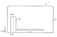
以下、本実施形態の一例に係る情報処理装置の姿勢を保持するための保持構造について説明する。図1は、本実施形態の情報処理装置の背面図の一例である。図2は、スタンド10を用いて情報処理装置1の姿勢が保持されているときの情報処理装置1の背面斜視図の一例である。
Hereinafter, a holding structure for holding the posture of the information processing apparatus according to an example of the present embodiment will be described. FIG. 1 is an example of a rear view of the information processing apparatus of this embodiment. FIG. 2 is an example of a rear perspective view of the
情報処理装置1は、略薄板状であり、横長の形状である。情報処理装置1は、アプリケーション(例えば、ゲームアプリケーション、その他の情報処理を行うためのアプリケーション等)を実行することが可能な装置であり、例えばゲーム装置、タブレット端末、スマートフォン等であってもよい。情報処理装置1は、例えば携帯型の装置であり、ユーザが両手又は片手で把持可能な大きさであってもよい。情報処理装置1の前面には、表示装置(図示せず)の画面が設けられる。また、情報処理装置1のハウジング2内にはバッテリーが設けられてもよい。
The
図1に示されるように、情報処理装置1の背面には、スタンド10が設けられる。スタンド10は、情報処理装置1の背面よりも上下方向(図1のx軸方向)の長さが短く、かつ、左右方向(図1のy軸方向)の長さが短い。例えば、スタンド10は、情報処理装置1を背面から見た場合に、左右方向における中央よりも左側に設けられる。
As shown in FIG. 1, a
スタンド10は、閉じられた状態では情報処理装置1の背面の一部を形成する。具体的には、図2に示されるように、情報処理装置1のハウジング2の背面の左下の領域には、スタンド10と略同じ大きさの収納部2aが形成されている。スタンド10は、閉じられた状態では収納部2aに収まる。ハウジング2の収納部2aの深さ(z軸方向の高さ)は、スタンド10の厚さ(z軸方向の厚さ)と略同じである。スタンド10が閉じられた状態では、スタンド10と、スタンド10以外のハウジング2の背面部分とは高さ(z軸方向の高さ)がほぼ一致する。すなわち、スタンド10が閉じられた状態では、ハウジング2の背面はスタンド10を含めて略平坦となり、スタンド10とスタンド10以外のハウジング2の背面との境界部分にはほぼ段差がない。
The
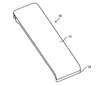
一方、スタンド10が開かれた状態では、図2に示されるように、スタンド10は背面方向に突出し、この突出したスタンド10によって、情報処理装置1の姿勢が保持される。
On the other hand, when the
図3は、情報処理装置1が載置面に載置され情報処理装置1の姿勢がスタンド10によって保持されたときの一例を示す図である。図3に示されるように、情報処理装置1の背面に設けられたスタンド10が開かれてテーブル等の載置面に載置された場合、情報処理装置1の前面(表示装置の画面)が、載置面に対して所定の角度を有するように斜め上方を向く。図3に示されるように、スタンド10の下端部には、滑り止めとなるストッパー部材12が設けられる。スタンド10は、その下端に行くにしたがって情報処理装置1に向かって情報処理装置1に向かって略円弧状に湾曲している。すなわち、スタンド10の下端部分は、R形状に形成されている。図3に示されるように、情報処理装置1の底面と背面との境界部分はR形状に形成されている。スタンド10が閉じられた状態では、スタンド10の下端部分におけるR形状の部分が、情報処理装置1の底面及び背面の境界部分のR形状の部分の一部を形成する。これにより、スタンド10を閉じたときに、情報処理装置1の底面および背面の境界部分は、情報処理装置1の左右方向(図3の紙面に垂直な方向)の略全体にわたってR形状となる。
FIG. 3 is a diagram showing an example when the
図4は、スタンド10を開いた状態で情報処理装置1を背面方向から見た図である。図5は、情報処理装置1の背面における収納部2aの部分拡大図である。
FIG. 4 is a view of the
図4に示されるように、情報処理装置1の背面の収納部2aには、メモリカード(例えば、microSDカード)を挿入するためのカードスロット3が設けられる。スタンド10は、カードスロット3のカバーとしても用いられる。すなわち、スタンド10は、開かれた状態では情報処理装置1を立たせてその姿勢を保持するために機能し、閉じられた状態ではカードスロット3のカバーとして機能する。
As shown in FIG. 4, a
図5に示されるように、情報処理装置1の背面の収納部2aには、一対の凹部4が形成される。この凹部4はスタンド10の突起部13(図7参照)と係合する係合部(被係合部)であり、情報処理装置1の凹部4とスタンド10の突起部13とが係合することにより、スタンド10を閉じた状態に維持する。
As shown in FIG. 5, a pair of
図6は、スタンド10を前面から見たときの斜視図である。図7は、スタンド10を背面から見たときの斜視図である。図8は、スタンド10の下端部の背面側の部分拡大図である。図9は、スタンド10が開いた状態から閉じた状態に移行する様子を示す図であってスタンド10の下端部および情報処理装置1のハウジング2の部分拡大図である。
FIG. 6 is a perspective view of the
図6〜図8に示されるように、スタンド10は、スタンド本体11と、スタンド本体11の下端部に設けられたストッパー部材12とを備える。また、スタンド本体11の下端部の背面側には、一対の突起部13が設けられる。また、スタンド本体11の上端部の背面側には、ヒンジ部14が設けられる。
As shown in FIGS. 6 to 8, the
スタンド本体11は、略長方形の薄板状の部材であり、下端部がスタンド本体11の背面方向(情報処理装置1の前面方向)に湾曲している。スタンド本体11は、例えばプラスチック等の合成樹脂によって形成される。なお、情報処理装置1のハウジング2も樹脂で形成される。突起部13は、スタンド本体11と一体的に形成される。突起部13は、スタンド10を閉じたときにハウジング2の凹部4と係合する係合部である。図9に示されるように、スタンド10が閉状態のときには、突起部13がハウジング2の凹部4に係合し、スタンド10を閉状態に維持する。
The stand
また、ストッパー部材12は、スタンド本体11よりも大きな摩擦係数を有する部材によって形成され、例えば、シリコンゴムによって形成される。具体的には、液状のシリコンゴムを用いてLIMS成形を行うことにより、スタンド本体11の下端部にシリコンゴムからなるストッパー部材12が密着形成される。
Further, the
ヒンジ部14は、金属(例えば鉄やアルミニウム等)によって形成されている。ヒンジ部14は、スタンド10全体を回動させるための部材である。ヒンジ部14は、ネジ17によってスタンド本体11に固定される。ヒンジ部14およびこれを回動可能に支持する構造については後述する。
The
次に、スタンド10の上端部分の詳細について説明する。
Next, the details of the upper end portion of the
図10は、情報処理装置1の断面の一例を示す図である。図10の(a)は、情報処理装置1の右側面図である。図10の(b)は、図10の(a)のB−B線断面図である。また、図11は、図10の(b)の破線部分を拡大した図である。
FIG. 10 is a diagram showing an example of a cross section of the
図10及び図11に示されるように、情報処理装置1の背面側のハウジング2には、スタンドホルダ15がネジによって固定される。スタンドホルダ15は、スタンド10を情報処理装置1に固定するための部材である。スタンドホルダ15は、例えば、プラスチック等の樹脂によって形成される。スタンドホルダ15は、例えば、スタンド本体11および情報処理装置1のハウジング2よりも硬い素材(強度の高い素材)によって形成されてもよい。
As shown in FIGS. 10 and 11, the
図11に示されるように、スタンドホルダ15は、クリッカ16(係止部)を情報処理装置1に固定する。図11に示されるように、スタンドホルダ15には2つの開口部が設けられ、この開口部にクリッカ16の一部が係合する。スタンドホルダ15とクリッカ16とは、異なる部材によって形成されており、これらは分離可能に形成される。クリッカ16は、ハウジング2およびスタンドホルダ15よりも柔らかい素材によって形成され、例えばエラストマー(例えば、TPE:Thermoplastic Elastomer)によって形成される。
As shown in FIG. 11, the
ヒンジ部14は、スタンド本体11の部分11aによって位置決めされ、ネジ17によってネジ止めされることでスタンド本体11に固定される。
The
スタンドホルダ15は、ヒンジ部14を回動可能に支持する。具体的には、スタンドホルダ15は、対向する一対の軸受部15a、15bを有する。ヒンジ部14は、左右方向に突出した一対の半球状の凸部14a、14bを有する。ヒンジ部14の凸部14aがスタンドホルダ15の軸受部15aに係合し、ヒンジ部14の凸部14bがスタンドホルダ15の軸受部15bに係合する。これにより、スタンドホルダ15は、ヒンジ部14及びスタンド本体11を、凸部14aと凸部14bとを結ぶ軸回りに回動可能に支持する。
The
より具体的には、図11に示されるように、スタンドホルダ15の軸受部15a、15bの内径は、ヒンジ部14の凸部14a、14bの外径よりも小さい。このため、スタンドホルダ15の軸受部15aによって、ヒンジ部14の凸部14aが完全に覆われることはない。すなわち、凸部14aの一部が軸受部15aに嵌合する。軸受部15bおよび凸部14bも同様である。
More specifically, as shown in FIG. 11, the inner diameters of the bearing
このようなスタンドホルダ15およびヒンジ部14の構造によって、ヒンジ部14を含めたスタンド本体11は、ヒンジ部14の凸部14aと凸部14bとを結ぶ軸回りに回動可能に支持される。ヒンジ部14の凸部14aおよび14bを結ぶ直線よりも下側のスタンド本体11の部分を情報処理装置1を支持する支持部11cとし、スタンド本体11における上記直線よりも上側の部分を突出部11bとすると、スタンド本体11が回動した場合、スタンド本体11の突出部11bの上端部は、クリッカ16に接触する。以下、スタンド本体11が回動するときのスタンド本体11の動きについて説明する。
Due to the structure of the
図12は、スタンド本体11が回動するときのスタンド本体11とクリッカ16との位置関係を示す図である。図12の下図ではスタンド本体11が閉状態(第1位置)から徐々に開状態(第2位置)に遷移する様子が示されている。図12の上図は下図の破線部分の拡大図である。図12においては、図1のA−A線断面図が示されているが、スタンド本体11およびクリッカ16の位置関係を説明するために必要な部分のみが示されており、その他の部分については簡略化されている。
FIG. 12 is a diagram showing a positional relationship between the
図12に示されるように、スタンド本体11は、ヒンジ部14の凸部14aおよび14bを結ぶ直線を回転軸として回動する。スタンド本体11が閉状態(図12の(a))からスタンド本体11を所定の角度(図12の(d)の状態よりも小さな角度)だけ反時計回りに回動させると、図12の(b)に示されるように、スタンド本体11の上端部(上記突出部11b。先端部ともいう)がクリッカ16と接触する。図12に示されるように、クリッカ16は、その下端部が情報処理装置1側(情報処理装置1の前面方向:z軸負方向)に向かって屈曲又は湾曲している。クリッカ16の下端部がz軸負方向に屈曲又は湾曲しているため、クリッカ16とスタンド本体10の上端部とが接触する位置は、クリッカ16が屈曲又は湾曲していない場合と比べて、図12の左寄りとなる。すなわち、クリッカ16が屈曲又は湾曲しているため、クリッカ16が屈曲又は湾曲していない場合と比べて、スタンド本体11をより大きく回転させなければスタンド本体11の上端部はクリッカ16と接触しない。
As shown in FIG. 12, the
図12の(b)の状態からスタンド本体11をさらに反時計回りに回動させると、クリッカ16がスタンド本体11の上端部によってz軸負方向に押されて弾性変形する。さらにスタンド本体11を回動させると、スタンド本体11の上端部がクリッカ16の下端部を越えて情報処理装置1の前面方向(z軸負方向)まで移動し、図12の(c)の状態となる。このときクリッカ16の変形が元に戻り、クリック音が鳴る。
When the
図12の(c)の状態からスタンド本体11をさらに回動させると、図12の(d)に示されるように、スタンド本体11の上端部がスタンドホルダ15の一部に当接する。具体的には、スタンド本体11の上端部は、スタンド本体11を閉じたときに斜めに傾斜する傾斜部を有する。この傾斜部の面は情報処理装置1側を向き、当該傾斜部の面がスタンドホルダ15の一部に当接する。図12の(d)の状態では、スタンド本体11はこれ以上回動しない。ここでは、スタンド本体11が最大限開かれた状態を「最大開状態(すなわち、図12の(d)に示す開状態)」ということにする。この最大開状態で図3に示すように情報処理装置1の姿勢が保持される。
When the stand
なお、上述のように、ヒンジ部14の凸部14a、bの外径はスタンドホルダ15の軸受部15a、bの内径よりも大きいため、ヒンジ部14はスタンドホルダ15から外れやすい。すなわち、ヒンジ部14の凸部14a、bは、その一部しか軸受部15a、bに嵌合しないため、ヒンジ部14に大きな力が加わると、ヒンジ部14はスタンドホルダ15から外れる。このため、図12の(d)の状態においてさらにスタンド10が開く方向(図12における反時計回り)に力が加わると、ヒンジ部14の凸部14a、bに力が加わり、その力がある限界を超えると、スタンド本体11を含むスタンド10の全体は、スタンドホルダ15から外れる。したがって、ユーザが、例えばスタンド10を強引に開いたり、スタンド10で情報処理装置1を立たせているときに情報処理装置1を踏んだりしても、スタンド10が情報処理装置1から外れるだけであり、スタンド10や情報処理装置1の背面におけるスタンド10を固定する部分が破損する可能性は低い。
As described above, since the outer diameters of the
このように、スタンド本体11が図12の(d)に示す最大開状態になる前に、スタンド本体11の上端部がクリッカ16に接触する。スタンド本体11の上端部がクリッカ16と接触することにより、ユーザは、スタンド本体11が最大開状態になる前に、スタンド本体11をどのくらい開くことができるかを認識することができる。また、本実施形態では、スタンド本体11の上端部がクリッカ16と接触する位置よりもさらにスタンド本体11が回動された場合、クリック音が鳴る。このクリック音によって、ユーザは最大開状態が近いことを認識することができる。すなわち、本実施形態では、スタンド本体11が最大開状態になる前にクリック音が鳴るため、ユーザは、スタンド本体11をどの位置まで開くことができるか容易に認識することができる。また、クリッカ16は、情報処理装置1の前面方向に屈曲又は湾曲しているため、スタンド本体11が最大開状態になる直前にクリック音が鳴る。これにより、スタンド10や情報処理装置1の背面におけるスタンド10を固定する部分が破損すること、又は/及び、スタンド10が情報処理装置1から外れてしまうことを防止することができる。
In this way, the upper end of the
また、図12の(d)に示されるように、スタンド本体11が最大開状態のときには、スタンド本体11の上端部はクリッカ16の下端部よりも情報処理装置1の前面方向側(z軸負方向側)に位置する。この状態からスタンド本体11が閉じる方向に回動されても、スタンド本体11の上端部がクリッカ16の下端部に接触し、クリッカ16は、スタンド本体11の時計回りへの回動(閉じる方向への回動)を係止する。
Further, as shown in FIG. 12D, when the stand
このように、スタンド本体11が最大開状態のときには、スタンド本体11が閉じる方向に回動することを抑制することができる。これにより、ユーザの意図に反してスタンド10が閉じることを防止することができ、情報処理装置1の姿勢を安定的に保持することができる。また、クリッカ16は、情報処理装置1の前面方向に屈曲又は湾曲しているため、スタンド本体11が最大開状態になっているときにあそびを小さくすることができる。すなわち、図12の(d)の状態のときのスタンド本体11とハウジング2とがなす角と、図12の(c)の状態のときのスタンド本体11とハウジング2とがなす角との差を小さくすることができる。これにより、スタンド本体11を用いて情報処理装置1を立たせているときに、情報処理装置1のぐらつきを小さくすることができる。なお、スタンド本体11が最大開状態のときにスタンド本体11の上端部がクリッカ16の下端部と接触するようにして、上記あそびを無くしてもよい。
As described above, when the stand
また、本実施形態ではヒンジ部14は金属で形成されるため、スタンド10の開閉が繰り返し行われてもヒンジ部14の凸部14a、bは磨耗しにくい。このため、スタンド10の開閉が繰り返し行われても、ヒンジ部14の凸部14a、bとスタンドホルダ15の軸受部15a、bとはしっかり係合し、スタンド本体11が外れやすくなったり、がたついたりすることを防止することができる。
Further, in the present embodiment, since the
また、本実施形態では、クリッカ16は弾性素材(例えばエラストマー)によって形成されるため、比較的変形し易く、スタンド本体11を開閉する際にスタンド本体11の上端部分がクリッカ16に接触してもユーザは比較的小さな力でスタンド本体11を開閉させることができる。
Further, in the present embodiment, since the
また、本実施形態では、スタンド本体11の上端部に傾斜部が設けられる。これにより、スタンド本体11の上端部がクリッカ16と接触する場合でも、クリッカ16を超えてスタンド本体11を回動させ易くすることができる。また、当該傾斜部がスタンドホルダ15の一部に面で接触するため、スタンド本体11を支え易く、スタンド本体11を最大開状態に維持させやすくすることができる。
Further, in the present embodiment, an inclined portion is provided at the upper end portion of the stand
また、本実施形態では、スタンド10の下端部にはストッパー部材12が設けられる。このため、スタンド10と載置面との摩擦を大きくすることができ、スタンド10が滑ることを防止することができる。また、スタンド10の下端部は、情報処理装置1の内側に向かって湾曲している(図3参照)。このため、ストッパー部材12が載置面と接触する接触面積を大きくすることができ、スタンド10が滑ることを防止することができる。
Further, in the present embodiment, the
また、本実施形態では、スタンドホルダ15、クリッカ16およびヒンジ部14は、それぞれ個別の部品として形成され、これらは分解可能に構成される。このため、例えば、繰り返しスタンド10の開閉が行われたことによってクリッカ16が磨耗した場合でも、クリッカ16を交換することができる。
Further, in the present embodiment, the
以上、本実施形態の情報処理装置1の姿勢を保持するためのスタンド10について説明したが、上記説明は単なる例示に過ぎず、種々の改良や変形が加えられてもよい。
The
例えば、上述したスタンド本体11、ストッパー部材12、ヒンジ部14、スタンドホルダ15、クリッカ16等の素材は単なる例示であり、これらの部材は他の素材によって形成されてもよい。また、これら各部材の形状は単なる例示であり、上述したものに限られない。
For example, the materials such as the
例えば、上記実施形態ではヒンジ部14は、凸部14aおよび14bを有し、略コの字型の形状としたが、ヒンジ部は他の形状でもよい。例えば、ヒンジ部は直線状の軸であってもよい。また、ヒンジ部は金属でなくてもよく樹脂によって形成されてもよい。
For example, in the above embodiment, the
また、上記実施形態では、クリッカ16は、情報処理装置1の前面方向に屈曲又は湾曲しているものとしたが、他の実施形態では、クリッカは直線状であってもよい。また、クリッカは、情報処理装置1の背面方向に屈曲又は湾曲してもよい。
Further, in the above embodiment, the
また、上記実施形態では、スタンド本体11は、回転軸(ヒンジ部14の凸部14aおよび14b)から上方に突出した突出部11bと、回転軸より下方の支持部11cとを有するものとし、突出部11bがクリッカ16と接触するように構成された。他の実施形態では、スタンド本体11の一部がクリッカ16と接触するように構成されていれば、スタンド本体11の形状はどのようなものでもよい。例えば、回転軸より下方にクリッカ16と接触する部分と、情報処理装置1を支持する支持部とが設けられてもよい。
Further, in the above embodiment, the stand
また、他の実施形態では、スタンド本体11にクリッカを設け、スタンド本体が回動するときに当該クリッカと接触する係止部が設けられてもよい。この場合、スタンド本体11に設けられたクリッカが変形することで上記クリック音が鳴ってもよい。
Further, in another embodiment, the stand
また、上記実施形態では、クリッカ16によってクリック音が鳴るものとしたが、必ずしもクリック音が鳴るものに限られない。例えば、スタンド本体が最大開状態になるまでにスタンド本体の一部が係止部に接触し、当該係止部によってスタンド本体の少なくとも一方向への回動が係止されていれば、ユーザにスタンド本体が最大開状態になる位置を認識させることはできる。
Further, in the above embodiment, the
また、上記実施形態では、図12の(d)に示されるように、スタンド本体11が最大開状態のときには、クリッカ16がスタンド本体11に接触しないようにして、いわゆる遊びを設けるようにした。他の実施形態では、スタンド本体11が最大開状態のときに、クリッカ16がスタンド本体11に接触してもよい。すなわち、図12の(d)の状態において、クリッカ16がスタンド本体11の上端部に接触するようにしてもよい。この場合において、クリッカ16がスタンド本体11の上端部を回動方向(スタンド本体11が閉状態(第1位置)から開状態(第2位置)になる方向。図12における反時計回り)に付勢するようにしてもよい。スタンド本体11が最大開状態のときにクリッカ16によってスタンド本体11が回動方向に付勢されることにより、スタンド本体11を最大開状態にしっかりと固定することができる。
Further, in the above embodiment, as shown in FIG. 12D, when the stand
1 情報処理装置
2 ハウジング
2a 収納部
3 メモリスロット
4 凹部
10 スタンド
11 スタンド本体
12 ストッパー部
13 突起部
14 ヒンジ部
14a、14b 凸部
15 スタンドホルダ
15a、15b 軸受部
16 クリッカ
1
Claims (19)
前記装置の姿勢を保持するための本体部と、当該本体部に固定され、前記装置の軸受部に着脱可能かつ回動可能に嵌合する軸部と、を備え、
前記軸部は、
前記軸受部に嵌合する曲面状の凸部を表面に有し、当該軸受部を結ぶ軸線に垂直な方向に延びる一対の第1部分と、
両端が前記一対の第1部分と接続する第2部分と、を有し、
前記凸部は、前記軸受部の開口部に嵌合する部分と、当該開口部から露出する部分とを有する、保持部材。 A holding member that is detachably attached to a device and holds the posture of the device.
A main body portion for holding the posture of the device and a shaft portion fixed to the main body portion and detachably and rotatably fitted to the bearing portion of the device are provided.
The shaft portion
A pair of first portions having a curved convex portion on the surface that fits into the bearing portion and extending in a direction perpendicular to the axis connecting the bearing portions.
A second portion having both ends connected to said pair of first portions, was closed,
The convex portion is a holding member having a portion that fits into the opening of the bearing portion and a portion that is exposed from the opening .
前記本体部は、
前記軸部から前記本体部の下端方向に伸びる前記装置を支持するための支持部と、
前記支持部の上端から突出し、前記本体部が前記軸部のまわりを回動するときに前記装置に固定された係止部と接触する突出部とを含む、請求項1から3の何れかに記載の保持部材。 The shaft portion is arranged on the upper part of the main body portion,
The main body
A support portion for supporting the device extending from the shaft portion toward the lower end of the main body portion, and a support portion.
One of claims 1 to 3 , which includes a protruding portion that protrudes from the upper end of the support portion and comes into contact with a locking portion fixed to the device when the main body portion rotates around the shaft portion. The holding member described.
前記本体部の下端部には、ストッパー部が設けられ、
前記ストッパー部は、前記本体部の下端部よりも摩擦係数の大きな素材からなる、請求項1から6の何れかに記載の保持部材。 The shaft portion is provided at the upper end portion of the main body portion, and is provided.
A stopper portion is provided at the lower end portion of the main body portion.
The holding member according to any one of claims 1 to 6 , wherein the stopper portion is made of a material having a friction coefficient larger than that of the lower end portion of the main body portion.
前記本体部の下端部は、前記装置に向かって湾曲又は屈曲する、請求項1から8の何れかに記載の保持部材。 The shaft portion is provided at the upper end portion of the main body portion, and is provided.
The holding member according to any one of claims 1 to 8 , wherein the lower end portion of the main body portion is curved or bent toward the device.
前記本体部は、開状態のときに前記装置の姿勢を保持し、
前記本体部の裏側には、前記本体部が閉状態のときに前記装置に設けられた被係合部と係合するための少なくとも1つの係合部が設けられる、請求項1から9の何れかに記載の保持部材。 The main body can rotate between the closed state and the open state.
The main body holds the posture of the device when it is in the open state.
Any of claims 1 to 9 , wherein at least one engaging portion for engaging with the engaged portion provided in the device is provided on the back side of the main body portion when the main body portion is in the closed state. Holding member described in Crab.
前記装置に着脱可能に取り付けられ、当該装置の姿勢を保持するための本体部と、
前記装置に固定された軸受部と、
前記本体部に固定され、前記軸受部に着脱可能かつ回動可能に嵌合する軸部と、を備え、
前記軸部は、
前記軸受部に嵌合する曲面状の凸部を表面に有し、当該軸受部を結ぶ軸線に垂直な方向に延びる一対の第1部分と、
両端が前記一対の第1部分と接続する第2部分と、を有し、
前記凸部は、前記軸受部の開口部に嵌合する部分と、当該開口部から露出する部分とを有する、保持構造。 A holding structure that holds the posture of the device
A main body that is detachably attached to the device and holds the posture of the device,
The bearing part fixed to the device and
A shaft portion fixed to the main body portion and detachably and rotatably fitted to the bearing portion is provided.
The shaft portion
A pair of first portions having a curved convex portion on the surface that fits into the bearing portion and extending in a direction perpendicular to the axis connecting the bearing portions.
A second portion having both ends connected to said pair of first portions, was closed,
The convex portion has a holding structure having a portion that fits into the opening of the bearing portion and a portion that is exposed from the opening .
前記装置の姿勢を保持するための本体部と、当該本体部に固定され、前記装置の軸受部に着脱可能かつ回動可能に嵌合する軸部と、を備え、
前記軸部は、
前記軸受部に嵌合する曲面状の凸部を表面に有し、当該軸受部を結ぶ軸線に垂直な方向に延びる一対の第1部分と、
両端が前記一対の第1部分と接続する第2部分と、を有し、
前記軸部における前記第2部分の中央部分が前記本体部に固定され、
前記軸部は略コの字状であり、前記本体部は、前記略コの字状の軸部の内側に沿うとともにネジ孔を備える位置決め部を有し、前記軸部は当該ネジ孔に挿入されるネジによって前記本体部に固定される、保持部材。 A holding member that is detachably attached to a device and holds the posture of the device.
A main body portion for holding the posture of the device and a shaft portion fixed to the main body portion and detachably and rotatably fitted to the bearing portion of the device are provided.
The shaft portion
A pair of first portions having a curved convex portion on the surface that fits into the bearing portion and extending in a direction perpendicular to the axis connecting the bearing portions.
A second portion having both ends connected to said pair of first portions, was closed,
The central portion of the second portion of the shaft portion is fixed to the main body portion,
The shaft portion has a substantially U-shape, and the main body portion has a positioning portion along the inside of the substantially U-shaped shaft portion and having a screw hole, and the shaft portion is inserted into the screw hole. A holding member that is fixed to the main body by screws .
前記装置に着脱可能に取り付けられ、当該装置の姿勢を保持するための本体部と、
前記装置に固定された軸受部と、
前記本体部に固定され、前記軸受部に着脱可能かつ回動可能に嵌合する軸部と、を備え、
前記軸部は、
前記軸受部に嵌合する曲面状の凸部を表面に有し、当該軸受部を結ぶ軸線に垂直な方向に延びる一対の第1部分と、
両端が前記一対の第1部分と接続する第2部分と、を有し、
前記軸部における前記第2部分の中央部分が前記本体部に固定され、
前記軸部は略コの字状であり、前記本体部は、前記略コの字状の軸部の内側に沿うとともにネジ孔を備える位置決め部を有し、前記軸部は当該ネジ孔に挿入されるネジによって前記本体部に固定される、保持構造。 A holding structure that holds the posture of the device
A main body that is detachably attached to the device and holds the posture of the device,
The bearing part fixed to the device and
A shaft portion fixed to the main body portion and detachably and rotatably fitted to the bearing portion is provided.
The shaft portion
A pair of first portions having a curved convex portion on the surface that fits into the bearing portion and extending in a direction perpendicular to the axis connecting the bearing portions.
A second portion having both ends connected to said pair of first portions, was closed,
The central portion of the second portion of the shaft portion is fixed to the main body portion,
The shaft portion has a substantially U-shape, and the main body portion has a positioning portion along the inside of the substantially U-shaped shaft portion and having a screw hole, and the shaft portion is inserted into the screw hole. A holding structure that is fixed to the main body by screws .
前記装置の姿勢を保持するための本体部と、当該本体部に固定され、前記装置の軸受部に着脱可能かつ回動可能に嵌合する軸部と、を備え、
前記軸部は、
前記軸受部に嵌合する曲面状の凸部を表面に有し、当該軸受部を結ぶ軸線に垂直な方向に延びる一対の第1部分と、
両端が前記一対の第1部分と接続する第2部分と、を有し、
前記軸部は前記本体部の上部に配置され、
前記本体部は、
前記軸部から前記本体部の下端方向に伸びる前記装置を支持するための支持部と、
前記支持部の上端から突出し、前記本体部が前記軸部のまわりを回動するときに前記装置に固定された係止部と接触する突出部とを含む、保持部材。 A holding member that is detachably attached to a device and holds the posture of the device.
A main body portion for holding the posture of the device and a shaft portion fixed to the main body portion and detachably and rotatably fitted to the bearing portion of the device are provided.
The shaft portion
A pair of first portions having a curved convex portion on the surface that fits into the bearing portion and extending in a direction perpendicular to the axis connecting the bearing portions.
A second portion having both ends connected to said pair of first portions, was closed,
The shaft portion is arranged on the upper part of the main body portion,
The main body
A support portion for supporting the device extending from the shaft portion toward the lower end of the main body portion, and a support portion.
A holding member including a protruding portion that protrudes from the upper end of the support portion and comes into contact with a locking portion fixed to the device when the main body portion rotates around the shaft portion .
前記装置に着脱可能に取り付けられ、当該装置の姿勢を保持するための本体部と、
前記装置に固定された軸受部と、
前記本体部に固定され、前記軸受部に着脱可能かつ回動可能に嵌合する軸部と、を備え、
前記軸部は、
前記軸受部に嵌合する曲面状の凸部を表面に有し、当該軸受部を結ぶ軸線に垂直な方向に延びる一対の第1部分と、
両端が前記一対の第1部分と接続する第2部分と、を有し、
前記軸部は前記本体部の上部に配置され、
前記本体部は、
前記軸部から前記本体部の下端方向に伸びる前記装置を支持するための支持部と、
前記支持部の上端から突出し、前記本体部が前記軸部のまわりを回動するときに前記装置に固定された係止部と接触する突出部とを含む、保持構造。 A holding structure that holds the posture of the device
A main body that is detachably attached to the device and holds the posture of the device,
The bearing part fixed to the device and
A shaft portion fixed to the main body portion and detachably and rotatably fitted to the bearing portion is provided.
The shaft portion
A pair of first portions having a curved convex portion on the surface that fits into the bearing portion and extending in a direction perpendicular to the axis connecting the bearing portions.
A second portion having both ends connected to said pair of first portions, was closed,
The shaft portion is arranged on the upper part of the main body portion,
The main body
A support portion for supporting the device extending from the shaft portion toward the lower end of the main body portion, and a support portion.
A holding structure including a protruding portion that protrudes from the upper end of the support portion and comes into contact with a locking portion fixed to the device when the main body portion rotates around the shaft portion .
前記装置の姿勢を保持するための本体部と、当該本体部の一面に固定され、前記装置の軸受部に着脱可能かつ回動可能に嵌合する軸部と、を備え、
前記軸部は、
前記軸受部に嵌合する、当該軸受部に向けて凸である一対の凸部と、
前記軸受部同士を結ぶ直線と平行に延びるように設けられる接続部分と、
前記接続部分の両端のそれぞれと、前記一対の凸部のそれぞれとを結ぶ一対のダンパー部分と、を有し、
前記一対のダンパー部分の全体が前記本体部の一面に覆われる、保持部材。 A holding member that is detachably attached to a device and holds the posture of the device.
A main body portion for holding the posture of the device and a shaft portion fixed to one surface of the main body portion and detachably and rotatably fitted to the bearing portion of the device are provided.
The shaft portion
A pair of convex portions that are fitted to the bearing portion and are convex toward the bearing portion,
A connecting portion provided so as to extend parallel to the straight line connecting the bearing portions,
It has a pair of damper portions connecting both ends of the connecting portion and each of the pair of convex portions.
A holding member in which the entire pair of damper portions is covered with one surface of the main body portion .
前記装置に着脱可能に取り付けられ、当該装置の姿勢を保持するための本体部と、
前記装置に固定された軸受部と、
前記本体部の一面に固定され、前記軸受部に着脱可能かつ回動可能に嵌合する軸部と、を備え、
前記軸部は、
前記軸受部に嵌合する、当該軸受部に向けて凸である一対の凸部と、
前記軸受部同士を結ぶ直線と平行に延びるように設けられる接続部分と、
前記接続部分の両端のそれぞれと、前記一対の凸部のそれぞれとを結ぶ一対のダンパー部分と、を有し、
前記一対のダンパー部分の全体が前記本体部の一面に覆われる、保持構造。 A holding structure that holds the posture of the device
A main body that is detachably attached to the device and holds the posture of the device,
The bearing part fixed to the device and
A shaft portion that is fixed to one surface of the main body portion and that is detachably and rotatably fitted to the bearing portion is provided.
The shaft portion
A pair of convex portions that are fitted to the bearing portion and are convex toward the bearing portion,
A connecting portion provided so as to extend parallel to the straight line connecting the bearing portions,
It has a pair of damper portions connecting both ends of the connecting portion and each of the pair of convex portions.
A holding structure in which the entire pair of damper portions is covered by one surface of the main body portion .
Priority Applications (1)
| Application Number | Priority Date | Filing Date | Title |
|---|---|---|---|
| JP2018209432A JP6791932B2 (en) | 2018-11-07 | 2018-11-07 | Holding structure of the device |
Applications Claiming Priority (1)
| Application Number | Priority Date | Filing Date | Title |
|---|---|---|---|
| JP2018209432A JP6791932B2 (en) | 2018-11-07 | 2018-11-07 | Holding structure of the device |
Related Parent Applications (1)
| Application Number | Title | Priority Date | Filing Date |
|---|---|---|---|
| JP2017001087A Division JP6684232B2 (en) | 2017-01-06 | 2017-01-06 | Device holding structure |
Publications (3)
| Publication Number | Publication Date |
|---|---|
| JP2019061687A JP2019061687A (en) | 2019-04-18 |
| JP2019061687A5 JP2019061687A5 (en) | 2020-02-13 |
| JP6791932B2 true JP6791932B2 (en) | 2020-11-25 |
Family
ID=66177473
Family Applications (1)
| Application Number | Title | Priority Date | Filing Date |
|---|---|---|---|
| JP2018209432A Active JP6791932B2 (en) | 2018-11-07 | 2018-11-07 | Holding structure of the device |
Country Status (1)
| Country | Link |
|---|---|
| JP (1) | JP6791932B2 (en) |
Families Citing this family (1)
| Publication number | Priority date | Publication date | Assignee | Title |
|---|---|---|---|---|
| JP7319323B2 (en) * | 2021-05-28 | 2023-08-01 | 任天堂株式会社 | Electronics and equipment holding systems |
Family Cites Families (8)
| Publication number | Priority date | Publication date | Assignee | Title |
|---|---|---|---|---|
| JPS59143079U (en) * | 1983-03-14 | 1984-09-25 | ソニー株式会社 | stand mechanism |
| JPS59182982U (en) * | 1983-05-24 | 1984-12-06 | 松下電器産業株式会社 | stand device |
| JP2005204005A (en) * | 2004-01-15 | 2005-07-28 | Nec Saitama Ltd | Main-body self-standing structure of mobile telephone wireless device and mobile telephone wireless device with main-body self-standing structure |
| CN101904661A (en) * | 2009-06-08 | 2010-12-08 | 鸿富锦精密工业(深圳)有限公司 | Equipment with bracket |
| TWI444033B (en) * | 2010-09-17 | 2014-07-01 | Htc Corp | Portable electronic device |
| JP5629602B2 (en) * | 2010-11-18 | 2014-11-26 | 株式会社ニフコ | Electronic equipment holder |
| JP5104939B2 (en) * | 2010-12-21 | 2012-12-19 | カシオ計算機株式会社 | Housing structure and electronic device |
| CN103883846A (en) * | 2012-12-24 | 2014-06-25 | 富泰华工业(深圳)有限公司 | support |
-
2018
- 2018-11-07 JP JP2018209432A patent/JP6791932B2/en active Active
Also Published As
| Publication number | Publication date |
|---|---|
| JP2019061687A (en) | 2019-04-18 |
Similar Documents
| Publication | Publication Date | Title |
|---|---|---|
| JP6684232B2 (en) | Device holding structure | |
| US7823747B2 (en) | Casing with flip cover | |
| US20100064475A1 (en) | Hinge assembly and electronic device using the same | |
| JP2017161066A (en) | Hinge assembly of electronic device | |
| EP2001207A2 (en) | Desktop charger holder | |
| US20210247814A1 (en) | Hinge structure and foldable electronic apparatus including the same | |
| KR20120138429A (en) | Cover case for portable device | |
| TW201331903A (en) | Multi-dimensional support structure of tablet display device | |
| TWI432128B (en) | Supporting apparatus of electronic device | |
| JP6103071B2 (en) | Electronic equipment and hinge unit | |
| JP6791932B2 (en) | Holding structure of the device | |
| US8149576B2 (en) | Information processing unit | |
| JP2017173433A (en) | Key guide structure for keyboard instrument | |
| JP2008132307A (en) | Compact container | |
| JP5473876B2 (en) | Touch pen | |
| JP4474568B2 (en) | Electronic device and rotatable display lock device | |
| US20070236109A1 (en) | Apparatus for positioning flipping cover and casing utilizing the same | |
| US8190218B2 (en) | Foldable handheld device | |
| JP5078804B2 (en) | Information processing device | |
| JP4016503B2 (en) | Electronic device having an open / close lid | |
| KR102298206B1 (en) | Tablet holder | |
| JP5331850B2 (en) | Hinge device and electronic device | |
| KR101565328B1 (en) | Support fixtures combine structrue and a reading desk having the same structrue | |
| CN218032373U (en) | Electronic equipment support | |
| JP2009152500A (en) | Portable apparatus |
Legal Events
| Date | Code | Title | Description |
|---|---|---|---|
| A521 | Request for written amendment filed |
Free format text: JAPANESE INTERMEDIATE CODE: A523 Effective date: 20191226 |
|
| A621 | Written request for application examination |
Free format text: JAPANESE INTERMEDIATE CODE: A621 Effective date: 20191226 |
|
| A977 | Report on retrieval |
Free format text: JAPANESE INTERMEDIATE CODE: A971007 Effective date: 20200731 |
|
| A131 | Notification of reasons for refusal |
Free format text: JAPANESE INTERMEDIATE CODE: A131 Effective date: 20200807 |
|
| A521 | Request for written amendment filed |
Free format text: JAPANESE INTERMEDIATE CODE: A523 Effective date: 20200907 |
|
| TRDD | Decision of grant or rejection written | ||
| A01 | Written decision to grant a patent or to grant a registration (utility model) |
Free format text: JAPANESE INTERMEDIATE CODE: A01 Effective date: 20201026 |
|
| A61 | First payment of annual fees (during grant procedure) |
Free format text: JAPANESE INTERMEDIATE CODE: A61 Effective date: 20201105 |
|
| R150 | Certificate of patent or registration of utility model |
Ref document number: 6791932 Country of ref document: JP Free format text: JAPANESE INTERMEDIATE CODE: R150 |
|
| R250 | Receipt of annual fees |
Free format text: JAPANESE INTERMEDIATE CODE: R250 |