JP6791663B2 - Filling device - Google Patents
Filling device Download PDFInfo
- Publication number
- JP6791663B2 JP6791663B2 JP2016127936A JP2016127936A JP6791663B2 JP 6791663 B2 JP6791663 B2 JP 6791663B2 JP 2016127936 A JP2016127936 A JP 2016127936A JP 2016127936 A JP2016127936 A JP 2016127936A JP 6791663 B2 JP6791663 B2 JP 6791663B2
- Authority
- JP
- Japan
- Prior art keywords
- speed
- sheet
- chute
- shutter
- contents
- Prior art date
- Legal status (The legal status is an assumption and is not a legal conclusion. Google has not performed a legal analysis and makes no representation as to the accuracy of the status listed.)
- Active
Links
Images
Landscapes
- Basic Packing Technique (AREA)
Description
本発明は、搬送方向に連続的に搬送されるシートに設けられた複数のポケット内に内容物を充填するための充填装置に関する。 The present invention relates to the filling equipment for filling the contents in a plurality of pockets provided in the sheet which is continuously transported in the transport direction.
特許文献1等の通り、プラスチック等のシートに設けられた複数のポケット内に、錠剤やカプセル剤等の固形薬剤、粒状の固形食品等の内容物を充填して、その後、アルミニウム箔等のカバーでポケットを覆う包装装置がある。包装装置は、搬送方向に連続的に搬送されるシートのポケット内に内容物を充填するための充填装置を備える。
As described in
特許文献2等の通り、充填装置は、搬送されるシートのポケット内に内容物を落下して充填するためのシュート部を備える。ポケットは、シートの搬送方向に連続的に直列されて、この直列が、搬送方向の直角方向に並列される。そのため、シュート部は、搬送方向の直角方向に並列された複数の案内路を備える。案内路の出口は、ポケットの開口に対応して配置され、案内路を通った内容物が、案内路の出口から落下してポケット内に充填される。 As described in Patent Document 2 and the like, the filling device includes a chute portion for dropping and filling the contents into the pocket of the sheet to be conveyed. The pockets are continuously serialized in the transport direction of the sheet, and the series is parallel in the direction perpendicular to the transport direction. Therefore, the chute portion includes a plurality of guide paths arranged in parallel in the direction perpendicular to the transport direction. The exit of the guideway is arranged corresponding to the opening of the pocket, and the contents passing through the guideway fall from the exit of the guideway and are filled in the pocket.
ところで、生産性を向上するために、内容物をポケット内に充填する速度を上げるという要望がある。その要望を満足するためには、シートの搬送速度を上げることが考えられる。その結果、内容物がポケット内に充填される速度が上がる。しかし、単にシートの搬送速度を上げるだけでは、ポケットの速度が速すぎるために、シュート部から落下する内容物がポケットから飛び出したり、内容物が割れたりする等の問題が生じる。 By the way, in order to improve productivity, there is a demand to increase the speed of filling the contents into the pocket. In order to satisfy the demand, it is conceivable to increase the sheet transport speed. As a result, the rate at which the contents are filled into the pocket is increased. However, simply increasing the sheet transport speed causes problems such as the contents falling from the chute popping out of the pockets and the contents cracking because the speed of the pocket is too high.
そこで、本発明が解決しようとする課題は、上記の問題点に鑑みて、内容物がポケットから飛び出したり割れたりすることなく、内容物をポケット内に充填する速度を上げることができる充填装置を提供することにある。 Therefore, an object of the present invention is to provide, in view of the above problems, without contents are cracked or jump out from the pocket, the filling equipment which can increase the rate of filling the contents into the pocket Is to provide.
上記の課題を解決するために、本発明に係る充填装置は、
搬送方向に搬送されるシートに設けられた複数のポケット内に内容物を充填するための充填装置であって、
シートを搬送方向に第1速度で連続的に搬送するための搬送機構と、
搬送方向に沿って所定間隔を置いて配置されると共に、搬送されるシートのポケット内に内容物を案内して落下するための複数のシュート部と、
各々のシュート部を搬送方向及び搬送方向の逆方向に往復移動するための移動機構と、
各々のシュート部の出口を開閉するためのシャッタ部と、を備え、
全て又は一部のシャッタ部が開き、シャッタ部が開かれたシュート部が、第1速度よりも遅い第2速度で、搬送方向に第1位置から第2位置へ進み、その後、シャッタ部の全部又は一部が閉じ、シャッタ部が閉じられたシュート部が、第3速度で、搬送方向の逆方向に第2位置から第1位置へ戻る動作を行い、動作を繰り返すことで、ポケット内に内容物が連続的に充填される。
In order to solve the above problems, the filling device according to the present invention
A filling device for filling a plurality of pockets provided in a sheet transported in the transport direction with the contents.
A transport mechanism for continuously transporting sheets at the first speed in the transport direction,
A plurality of chute portions for guiding the contents into the pockets of the sheets to be transported and dropping them while being arranged at predetermined intervals along the transport direction.
A moving mechanism for reciprocating each chute in the transport direction and in the opposite direction of the transport direction,
A shutter unit for opening and closing the outlet of each chute unit is provided.
All or part of the shutter part is opened , and the shoot part with the shutter part opened advances from the first position to the second position in the transport direction at a second speed slower than the first speed, and then all of the shutter part . or Ji partially closed, the chute portion shutter portion is closed, at a third speed, performs the operation returns from the second position in the direction opposite to the conveying direction to the first position, by repeating the operation, the pocket The contents are continuously filled.
好ましくは、
第2速度は、第1速度の1/2である。
Preferably,
The second speed is 1/2 of the first speed.
好ましくは、
第3速度は、第1速度よりも速い。
Preferably,
The third speed is faster than the first speed.
好ましくは、
各々のシュート部及び各々のシャッタ部は、それぞれが同じタイミングで動作を行う。
Preferably,
Each shoot unit and each shutter unit operate at the same timing.
好ましくは、
各々のシュート部及び各々のシャッタ部は、それぞれが異なるタイミングで動作を行う。
Preferably,
Each shoot unit and each shutter unit operate at different timings.
本発明に係る充填装置は、内容物がポケットから飛び出したり割れたりすることなく、内容物をポケット内に充填する速度を上げることができる。 The filling device according to the present invention can increase the speed of filling the contents into the pocket without the contents popping out or cracking from the pocket.
以下、図面に基づいて、本発明に係る充填装置の一実施形態を説明する。 Hereinafter, an embodiment of the filling device according to the present invention will be described with reference to the drawings.
[全体構成]
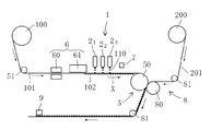
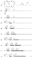
図1の通り、包装装置は、錠剤やカプセル剤等の固形薬剤、粒状の固形食品等の内容物110を包装する。包装装置は、プラスチック等のシート101がロール状に巻き取られてなるシートロール部100を備える。
[overall structure]
As shown in FIG. 1, the packaging device packages solid chemicals such as tablets and capsules, and
包装装置は、シート101に設けられた複数のポケット102内に内容物を充填するための充填装置1を備える。充填装置1は、シート101を搬送方向Xに搬送するために搬送機構5を備える。搬送機構5は、駆動ローラ50及び従動ローラ51を備える。各ローラ50,51は、シートロール部100からシート101を巻き出して、シート101を第1速度V1で停止することなく連続的に搬送する。
The packaging device includes a
包装装置は、シート101にポケット102を成形するためのポケット成形装置6を備える。ポケット成形装置6は、加熱装置60と成形装置61とを備える。加熱装置60は、シート101を加熱して軟らかくする。成形装置61は、凹部又は凸部を有する金型(不図示)を、加熱装置60で加熱されたシート101に押し当てて、シート101にポケット102を形成する。ポケット102は、シート101の搬送方向Xに連続的に直列されて、この直列が、搬送方向Xの直角方向Yに等間隔を置いて並列される(図2)。
The packaging device includes a pocket molding device 6 for molding the
充填装置1は、搬送方向Xに沿って配列された複数のシュート部21,22,23を備える。
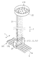
図2の通り、シュート部2(21,22,23)は、直角方向Yに等間隔を置いて配列された筒状の案内路20を備える。各案内路20は、上下方向Zに延設されており、ポケット102に対応して配置される。案内路20を通じる内容物110は、搬送されるシート101のポケット102内に落下して充填される。
The
As shown in FIG. 2, the chute portions 2 (2 1 , 2 2 , 2 3 ) include
シュート部2は、各案内路20に接続されたコイルスプリング21と、コイルスプリング21に接続されたパーツフィーダ22と、を備える。コイルスプリング21は、上下方向Zに延設されて、可撓性を有する。パーツフィーダ22は、複数の内容物110が収納されており、振動部(不図示)で振動される。パーツフィーダ22が振動することで、収納された内容物110が、コイルスプリング21内に導かれて落下する。
The chute portion 2 includes a
図1の通り、包装装置は、検査装置7を備える。検査装置7は、内容物110が各ポケット102内に確実に充填されているか否か、内容物110の形状や色等の異常の有無、異物がポケット102内に混入されているか否か等を検査する。後述する切断装置9で、シート101は所定長さごとに打ち抜かれるが、検査装置7で不良と判定されたポケット102を含むシート101は、排出装置(不図示)で排出される。
As shown in FIG. 1, the packaging device includes an
包装装置は、アルミニウム箔等のカバー201がロール状に巻き取られてなるカバーロール部200を備える。包装装置は、駆動ローラ80及び従動ローラ81を備える。各ローラ80,81は、カバーロール部200からカバー201を巻き出して、カバー201を搬送する。シート101及びカバー201は、ローラ50,80で重ねられて挟まれて搬送される。ローラ50,80は、熱源(不図示)を備えており、重ねられたシート101及びカバー201を加熱して密着する。
The packaging device includes a
包装装置は、切断装置9を備える。切断装置9は、カバー201で覆われたシート101を所定長さごとに打ち抜く。打抜かれたシート101は、落下して後処理装置(不図示)に搬送される。
The packaging device includes a
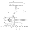
図3の通り、充填装置1は、シュート部2を搬送方向X及びその逆方向に往復移動するための移動機構3を備える。移動機構3は、シュート部2に支持されたステッピングモータ30と、モータ30に接続されたピニオン31と、を備える。また、移動機構3は、包装装置のフレームに固定されたラック32を備える。ラック32は、搬送方向Xに延設される。ラック32及びピニオン31は係合している。モータ30の正逆回転の出力によって、シュート部2は、ラック32及びピニオン31を介して、搬送方向X及びその逆方向に往復移動する。
As shown in FIG. 3, the filling
充填装置1は、シュート部2の案内路20の出口20aを開閉するためのシャッタ部4を備える。シャッタ部4は、シュート部2に支持されたアクチュエータ部40で往復移動する。シャッタ部4が出口20aを開けると、内容物110がポケット102内に充填可能となり、シャッタ部4が出口20aを閉じると、内容物110がポケット102内に充填不能となる。
The filling
[第1実施形態]
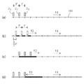
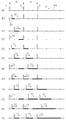
図4(a)の通り、本実施形態では、第1、第2及び第3シュート部21,22,23が等距離Pを置いて配置される。シート101の距離Pの間で、所定の複数のポケット102が配置されている。シート101は、一定の第1速度V1で連続的に搬送される。
図4(a)〜(d)は、それぞれ、シート101が距離Pだけ進んだ状態を示す。
[First Embodiment]
As FIG. 4 (a), in the present embodiment, first, second and third chute section 2 1, 2 2, 2 3 are arranged at equal distance P. A plurality of
4 (a) to 4 (d) show a state in which the
シャッタ部4が開いた状態で、各シュート部21,22,23は、第1速度V1の1/2の第2速度V2(=1/2×V1)で、シート101の搬送方向Xに、第1位置(図4(a))から中間位置(図4(b))を経て第2位置(図4(c))に進む。ここで、各シュート部21,22,23が第1位置及び第2位置に配置されるとき、各シュート部21,22,23の案内路20の出口20aの直下にポケット102が配置される。
With the
そのため、シュート部21,22,23が第1位置(図4(a))から中間位置(図4(b))に進む間では、シャッタ部4が開いた状態で、シート101は距離Pだけ進み、各シュート部21,22,23は距離1/2Pだけ進むので、シート101の距離1/2Pのポケット102に内容物110が充填される(図4(b)の太線部分)。
Therefore, while the shoot portions 2 1 , 2 2 , and 2 3 advance from the first position (FIG. 4 (a)) to the intermediate position (FIG. 4 (b)), the
また、シュート部21,22,23が第1位置(図4(a))から第2位置(図4(c))に進む間では、シャッタ部4が開いた状態で、シート101は距離2Pだけ進み、各シュート部21,22,23は距離Pだけ進むので、シート101の距離Pのポケット102に内容物110が充填される(図4(c)の太線部分)。
Further, while the shoot portions 2 1 , 2 2 , and 2 3 advance from the first position (FIG. 4 (a)) to the second position (FIG. 4 (c)), the
その後、シャッタ部4が閉じた状態で、各シュート部21,22,23は、第1速度V1より速い第3速度V3(>V1)で、搬送方向Xの逆方向に、第2位置(図4(c))から第1位置(図4(d))に戻る。
After that, with the
シュート部21,22,23が第2位置(図4(c))から第1位置(図4(d))に戻る間では、シート101は距離Pだけ進み、各シュート部21,22,23は距離Pだけ戻る。
なお、シート101と各シュート部21,22,23とが同一距離Pだけ移動するにも拘らず、第3速度V3が第1速度V1よりも速い理由は、第2位置(図4(c))でシャッタ部4を閉じる間、及び、第1位置(図4(d))でシャッタ部4を開く間、各シュート部21,22,23が短時間だけ停止して、時間ロスが生じるからである。
While the shoot portions 2 1 , 2 2 , and 2 3 return from the second position (FIG. 4 (c)) to the first position (FIG. 4 (d)), the
Note that regardless the
その後は、上記した通り、シャッタ部4が開いた状態で、シュート部21,22,23が第1位置(図4(a))から第2位置(図4(c))へ進み、その後、シャッタ部4が閉じた状態で、シュート部21,22,23が第2位置(図4(c))から第1位置(図4(d))へ戻る動作を1サイクルとして、この動作を繰り返し行うことで、ポケット102内に内容物110が連続的に充填される。そして、各シュート部21,22,23及びそのシャッタ部4は、それぞれ同じタイミングで同一動作を行う。
Thereafter, as described above, in a state where the
なお、シュート部21,22,23がポケット102内に内容物110を充填する間では、シート101の第1速度V1とシュート部21,22,23の第2速度V2(=1/2×V1)との相対速度は1/2×V1(=V1−V2=V1−1/2×V1)となる。そのため、シート101の第1速度V1が、従来の最大搬送速度V’の2倍であっても(V1=2×V’)、相対速度1/2×V1(=1/2×2×V’=V’)は、従来の最大搬送速度V’と同一である。
Incidentally, among the chute 2 1, 2 2, 2 3 fills the
即ち、シート101の第1速度V1を従来の最大搬送速度V’の2倍にしても、シュート部2とシート101との相対速度が従来の最大相対速度V’と同一である。そのため、内容物110がポケット102から飛び出したり割れたりすることなく、内容物110をポケット102に充填する速度を2倍できる。
That is, even if the first speed V1 of the
各シュート部21,22,23がそれぞれ同じタイミングで同一動作を行うので、移動機構3を各シュート部21,22,23に対して共通にできる。また、そのために、各シュート部21,22,23を一体とすることができる。
また、各シャッタ部4がそれぞれ同じタイミングで開閉を行うので、アクチュエータ部40を各シャッタ部4に対して共通にできる。また、そのために、各シャッタ部4を一体とすることができる。
Each chute section 2 1, 2 2, 2 3 performs the same operation at the same timing, respectively, can be a moving
Further, since each
[第2実施形態]
重複説明を避けるため、上記実施形態と同じ点は説明を省略することがある。
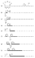
図5(a)の通り、本実施形態では、第1、第2及び第3シュート部21,22,23が等距離2×Pを置いて配置される。シート101は、一定の第1速度V1で連続的に搬送される。
図5(a)〜(j)は、それぞれ、シート101が距離Pだけ進んだ状態を示す。
[Second Embodiment]
In order to avoid duplicate explanations, the same points as in the above embodiment may be omitted.
As in FIG. 5 (a), in the present embodiment, first, second and third chute section 2 1, 2 2, 2 3 are spaced equidistant 2 × P. The
5 (a) to 5 (j) show a state in which the
第1シュート部21は、シャッタ部4が開いた状態で、第1速度V1の1/2の第2速度V2(=1/2×V1)で、シート101の搬送方向Xに、第1位置(図5(a))から中間位置(図5(b))を経て第2位置(図5(c))に進む。
The first shoot unit 2 1 is the first in the transport direction X of the
その後、第1シュート部21は、シャッタ部4が閉じた状態で、第1速度V1より速い第3速度V3(>V1)で、搬送方向Xの逆方向に、第2位置(図5(c))から第1位置(図5(d))に戻る。
Thereafter, the first chute section 2 1, in a state where the
その後は、第1シュート部21は、シャッタ部4が開いた状態で、第1位置(図5(d))から第2位置(図5(f))へ進み、その後、シャッタ部4が閉じた状態で、第2位置(図5(f))から第1位置(図5(g))へ戻る動作を1サイクルとして、この動作を繰り返し行う。
Thereafter, the first chute section 2 1, in a state where the
次に、第2シュート部22は、シャッタ部4が開いた状態で、第2速度V2で、搬送方向Xに、第1位置(図5(d))から中間位置(図5(e))を経て第2位置(図5(f))に進む。
Next, the second shoot portion 2 2 is in a state where the
その後、第2シュート部22は、シャッタ部4が閉じた状態で、第3速度V3で、搬送方向Xの逆方向に、第2位置(図5(f))から第1位置(図5(g))に戻る。
After that, the second shoot unit 2 2 is moved from the second position (FIG. 5 (f)) to the first position (FIG. 5) in the direction opposite to the transport direction X at the third speed V3 with the
その後は、第2シュート部22は、シャッタ部4が開いた状態で、第1位置(図5(g))から第2位置(図5(i))へ進み、その後、シャッタ部4が閉じた状態で、第2位置(図5(i))から第1位置(図5(j))へ戻る動作を1サイクルとして、この動作を繰り返し行う。
After that, the second shoot portion 2 2 advances from the first position (FIG. 5 (g)) to the second position (FIG. 5 (i)) with the
次に、第3シュート部23は、シャッタ部4が開いた状態で、第2速度V2で、搬送方向Xに、第1位置(図5(g))から中間位置(図5(h))を経て第2位置(図5(i))に進む。
Next, the third chute section 2 3, in a state where the
その後、第3シュート部23は、シャッタ部4が閉じた状態で、第3速度V3で、搬送方向Xの逆方向に、第2位置(図5(i))から第1位置(図5(j))に戻る。
Thereafter, the third chute section 2 3, in a state where the
その後は、第3シュート部23は、シャッタ部4が開いた状態で、第1位置(図5(j))から第2位置(図5(i))へ進み、その後、シャッタ部4が閉じた状態で、第2位置(図5(i))から第1位置(図5(j))へ戻る動作を1サイクルとして、この動作を繰り返し行う。
Thereafter, the third chute section 2 3, in a state where the
上記の通り、各シュート部21,22,23及びそのシャッタ部4は、動作の初期段階では、それぞれ異なるタイミングで同一動作を行い、その後の段階では、それぞれ同じタイミングで同一動作を行い、この動作を繰り返し行うことで、ポケット102内に内容物110が連続的に充填される。
As described above, each chute section 2 1, 2 2, 2 3, and the
[第3実施形態]
重複説明を避けるため、上記実施形態と同じ点は説明を省略することがある。
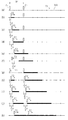
図6(a)の通り、本実施形態では、第1、第2及び第3シュート部21,22,23が等距離3×Pを置いて配置される。シート101は、一定の第1速度V1で連続的に搬送される。
図6(a)〜(l)は、それぞれ、シート101が距離Pだけ進んだ状態を示す。
[Third Embodiment]
In order to avoid duplicate explanations, the same points as in the above embodiment may be omitted.
As Figure 6 (a), in the present embodiment, first, second and third chute section 2 1, 2 2, 2 3 are spaced equidistant 3 × P. The
6 (a) to 6 (l) show a state in which the
第1シュート部21は、シャッタ部4が開いた状態で、第1速度V1の1/2の第2速度V2(=1/2×V1)で、シート101の搬送方向Xに、第1位置(図6(a))から中間位置(図6(b))を経て第2位置(図6(c))に進む。
The first shoot unit 2 1 is the first in the transport direction X of the
その後、第1シュート部21は、シャッタ部4が閉じた状態で、第1速度V1より速い第3速度V3(>V1)で、搬送方向Xの逆方向に、第2位置(図6(c))から第1位置(図6(d))に戻る。
Thereafter, the first chute section 2 1, in a state where the
その後は、第1シュート部21は、シャッタ部4が開いた状態で、第1位置(図6(d))から第2位置(図6(f))へ進み、その後、シャッタ部4が閉じた状態で、第2位置(図6(f))から第1位置(図6(g))へ戻る動作を1サイクルとして、この動作を繰り返し行う。
Thereafter, the first chute section 2 1, in a state where the
次に、第2シュート部22は、シャッタ部4が開いた状態で、第2速度V2で、搬送方向Xに、第1位置(図6(e))から中間位置(図6(f))を経て第2位置(図6(g))に進む。
Next, the second shoot portion 2 2 is in a state where the
その後、第2シュート部22は、シャッタ部4が閉じた状態で、第3速度V3で、搬送方向Xの逆方向に、第2位置(図6(g))から第1位置(図6(h))に戻る。
After that, the second shoot unit 2 2 is moved from the second position (FIG. 6 (g)) to the first position (FIG. 6) in the direction opposite to the transport direction X at the third speed V3 with the
その後は、第2シュート部22は、シャッタ部4が開いた状態で、第1位置(図6(h))から第2位置(図6(j))へ進み、その後、シャッタ部4が閉じた状態で、第2位置(図6(j))から第1位置(図6(k))へ戻る動作を1サイクルとして、この動作を繰り返し行う。
After that, the second shoot portion 2 2 advances from the first position (FIG. 6 (h)) to the second position (FIG. 6 (j)) with the
次に、第3シュート部23は、シャッタ部4が開いた状態で、第2速度V2で、搬送方向Xに、第1位置(図6(i))から中間位置(図6(j))を経て第2位置(図6(k))に進む。
Next, the third chute section 2 3, in a state where the
その後、第3シュート部23は、シャッタ部4が閉じた状態で、第3速度V3で、搬送方向Xの逆方向に、第2位置(図6(k))から第1位置(図6(l))に戻る。
Thereafter, the third chute section 2 3, in a state where the
その後は、第3シュート部23は、シャッタ部4が開いた状態で、第1位置(図6(l))から第2位置(図6(k))へ進み、その後、シャッタ部4が閉じた状態で、第2位置(図6(k))から第1位置(図6(l))へ戻る動作を1サイクルとして、この動作を繰り返し行う。
Thereafter, the third chute section 2 3, in a state where the
上記の通り、各シュート部21,22,23及びそのシャッタ部4は、それぞれ異なるタイミングで同一動作を行い、この動作を繰り返し行うことで、ポケット102内に内容物110が連続的に充填される。
As described above, each chute section 2 1, 2 2, 2 3 and the
[第4実施形態]
重複説明を避けるため、上記実施形態と同じ点は説明を省略することがある。
図7(a)の通り、本実施形態では、第1及び第2シュート部21,22が距離2×Pを置いて配置される。シート101は、一定の第1速度V1で連続的に搬送される。
図7(a)〜(i)は、それぞれ、シート101が距離Pだけ進んだ状態を示す。
[Fourth Embodiment]
In order to avoid duplicate explanations, the same points as in the above embodiment may be omitted.
As in FIG. 7 (a), in the present embodiment, the first and second chute section 2 1, 2 2 are arranged at a distance 2 × P. The
7 (a) to 7 (i) show a state in which the
第1シュート部21は、シャッタ部4が開いた状態で、第1速度V1の1/3の第2速度V2(=1/3×V1)で、シート101の搬送方向Xに、第1位置(図7(a))から中間位置(図7(b)及び(c))を経て第2位置(図7(d))に進む。
The first shoot unit 2 1 is the first in the transport direction X of the
その後、第1シュート部21は、シャッタ部4が閉じた状態で、第1速度V1より速い第3速度V3(>V1)で、搬送方向Xの逆方向に、第2位置(図7(d))から第1位置(図7(e))に戻る。
Thereafter, the first chute section 2 1, in a state where the
その後は、第1シュート部21は、シャッタ部4が開いた状態で、第1位置(図7(e))から第2位置(図7(h))へ進み、その後、シャッタ部4が閉じた状態で、第2位置(図7(h))から第1位置(図7(i))へ戻る動作を1サイクルとして、この動作を繰り返し行う。
Thereafter, the first chute section 2 1, in a state where the
次に、第2シュート部22は、シャッタ部4が開いた状態で、第2速度V2で、搬送方向Xに、第1位置(図7(e))から中間位置(図7(f)及び(g))を経て第2位置(図7(h))に進む。
Next, the second shoot unit 2 2 is in a state where the
その後、第2シュート部22は、シャッタ部4が閉じた状態で、第3速度V3で、搬送方向Xの逆方向に、第2位置(図7(h))から第1位置(図7(i))に戻る。
After that, the second shoot portion 2 2 is moved from the second position (FIG. 7 (h)) to the first position (FIG. 7) in the direction opposite to the transport direction X at the third speed V3 with the
その後は、第2シュート部22は、シャッタ部4が開いた状態で、第1位置(図7(i))から第2位置(図7(h))へ進み、その後、シャッタ部4が閉じた状態で、第2位置(図7(h))から第1位置(図7(i))へ戻る動作を1サイクルとして、この動作を繰り返し行う。
After that, the second shoot unit 2 2 advances from the first position (FIG. 7 (i)) to the second position (FIG. 7 (h)) with the
上記の通り、各シュート部21,22及びそのシャッタ部4は、それぞれ異なるタイミングで同一動作を行い、この動作を繰り返し行うことで、ポケット102内に内容物110が連続的に充填される。
As described above, each of the shoot portions 2 1 and 2 2 and the
なお、シュート部21,22がポケット102内に内容物110を充填する間では、シート101の第1速度V1とシュート部21,22の第2速度V2(=1/3×V1)との相対速度は2/3×V1(=V1−V2=V1−1/3×V1)となる。そのため、シート101の第1速度V1が、従来の最大速度V’の3/2倍であっても(V1=3/2×V’)、相対速度2/3×V1は、従来の最大速度V’と同一である。
Incidentally,
即ち、シート101の第1速度V1を従来の最大搬送速度V’の3/2倍にしても、シュート部2とシート101との相対速度が従来の最大相対速度V’と同一なので、内容物110がポケット102から飛び出したり割れたりすることがない。
That is, even if the first speed V1 of the
[第5実施形態]
重複説明を避けるため、上記実施形態と同じ点は説明を省略することがある。
図8(a)の通り、本実施形態では、第1及び第2シュート部21,22が距離3×Pを置いて配置される。シート101は、一定の第1速度V1で連続的に搬送される。
図8(a)〜(k)及び図9(a)〜(b)は、それぞれ、シート101が距離Pだけ進んだ状態を示す。
[Fifth Embodiment]
In order to avoid duplicate explanations, the same points as in the above embodiment may be omitted.
As in FIG. 8 (a), in the present embodiment, the first and second chute section 2 1, 2 2 are arranged at a
8 (a) to 8 (k) and FIGS. 9 (a) to 9 (b) show a state in which the
第1シュート部21は、シャッタ部4が開いた状態で、第1速度V1の1/4の第2速度V2(=1/4×V1)で、シート101の搬送方向Xに、第1位置(図8(a))から中間位置(図8(b)〜(d))を経て第2位置(図8(e))に進む。
The first chute section 2 1, in a state where the
その後、第1シュート部21は、シャッタ部4が閉じた状態で、第1速度V1より遅い第3速度V3(<V1)で、搬送方向Xの逆方向に、第2位置(図8(e))から中間位置(図8(f))を経て第1位置(図8(g))に戻る。
Thereafter, the first chute section 2 1, in a state where the
その後は、第1シュート部21は、シャッタ部4が開いた状態で、第1位置(図8(g))から第2位置(図8(k))へ進み、その後、シャッタ部4が閉じた状態で、第2位置(図8(k))から第1位置(図9(b))へ戻る動作を1サイクルとして、この動作を繰り返し行う。
Thereafter, the first chute section 2 1, in a state where the
次に、第2シュート部22は、シャッタ部4が開いた状態で、第2速度V2で、搬送方向Xに、第1位置(図8(g))から中間位置(図8(h)〜(j))を経て第2位置(図8(k))に進む。
Next, the second shoot unit 2 2 is in a state where the
その後、第2シュート部22は、シャッタ部4が閉じた状態で、第3速度V3で、搬送方向Xの逆方向に、第2位置(図8(k))から中間位置(図9(a))を経て第1位置(図9(b))に戻る。
After that, the second shoot unit 2 2 is in a state where the
その後は、第2シュート部22は、シャッタ部4が開いた状態で、第1位置(図9(b))から第2位置(図8(k))へ進み、その後、シャッタ部4が閉じた状態で、第2位置(図8(k))から第1位置(図9(b))へ戻る動作を1サイクルとして、この動作を繰り返し行う。
After that, the second shoot portion 2 2 advances from the first position (FIG. 9 (b)) to the second position (FIG. 8 (k)) with the
上記の通り、各シュート部21,22及びそのシャッタ部4は、それぞれ異なるタイミングで同一動作を行い、この動作を繰り返し行うことで、ポケット102内に内容物110が連続的に充填される。
As described above, each of the shoot portions 2 1 and 2 2 and the
なお、シュート部21,22がポケット102内に内容物110を充填する間では、シート101の第1速度V1とシュート部21,22の第2速度V2(=1/4×V1)との相対速度は3/4×V1(=V1−V2=V1−1/4×V1)となる。そのため、シート101の第1速度V1が、従来の最大速度V’の4/3倍であっても(V1=4/3×V’)、相対速度3/4×V1は、従来の最大速度V’と同一である。
Incidentally,
即ち、シート101の第1速度V1を従来の最大搬送速度V’の4/3倍にしても、シュート部2とシート101との相対速度が従来の最大相対速度V’と同一なので、内容物110がポケット102から飛び出したり割れたりすることがない。
また、第5実施形態では、第1〜第4実施形態よりも、シュート部2の第2速度V2及び第3速度V3が遅いので、移動機構3及びシャッタ部4の駆動の負荷を小さくできる。
That is, even if the first speed V1 of the
Further, in the fifth embodiment, since the second speed V2 and the third speed V3 of the shoot unit 2 are slower than those in the first to fourth embodiments, the drive load of the moving
以上、本発明の好ましい実施形態を説明したが、本発明の構成はこれらの実施形態に限定されるものではない。
・各シュート部は、等間隔でなく異なる間隔を置いて配置されてもよい。
・各シュート部及び各シャッタ部は、それぞれが異なるタイミング、第2速度及び第3速度で動作を行ってもよい。
・移動機構3は、サーボモータを用いたボールねじ機構など、様々な公知技術を採用できる。
・搬送機構5は、少なくとも内容物がポケット102内に充填される間で、連続的にシート101を搬送すればよく、その他の区間、例えば、シート101にポケット102が成形される間、又は、カバー201がシート101に密着される間では、間欠的にシート101を搬送してもよい。
Although the preferred embodiments of the present invention have been described above, the configuration of the present invention is not limited to these embodiments.
-Each chute may be arranged at different intervals rather than at equal intervals.
-Each shoot unit and each shutter unit may operate at different timings, second speed, and third speed.
-The
The
1 充填装置
2 シュート部
3 移動機構
4 シャッタ部
5 搬送機構
101 シート
102 ポケット
110 内容物
X 搬送方向
V1 第1速度
V2 第2速度
V3 第3速度
1 Filling device 2
Claims (5)
前記シートを前記搬送方向に第1速度で連続的に搬送するための搬送機構と、
前記搬送方向に沿って所定間隔を置いて配置されると共に、搬送される前記シートの前記ポケット内に前記内容物を案内して落下するための複数のシュート部と、
各々の前記シュート部を前記搬送方向及び前記搬送方向の逆方向に往復移動するための移動機構と、
各々の前記シュート部の出口を開閉するためのシャッタ部と、を備え、
全て又は一部の前記シャッタ部が開き、前記シャッタ部が開かれた前記シュート部が、前記第1速度よりも遅い第2速度で、前記搬送方向に第1位置から第2位置へ進み、その後、開かれた前記シャッタ部が閉じ、前記シャッタ部が閉じられた前記シュート部が、第3速度で、前記搬送方向の逆方向に前記第2位置から前記第1位置へ戻る動作を行い、前記動作を繰り返すことで、前記ポケット内に前記内容物が連続的に充填される
ことを特徴とする充填装置。 A filling device for filling a plurality of pockets provided in a sheet transported in the transport direction with the contents.
A transport mechanism for continuously transporting the sheet in the transport direction at the first speed, and
A plurality of chute portions for guiding and dropping the contents into the pockets of the sheets to be transported while being arranged at predetermined intervals along the transport direction.
A moving mechanism for reciprocating the respective front carboxymethyl chute portion in the opposite direction of the conveying direction and the conveying direction,
And a shutter portion for opening and closing the outlet of the pre-carboxymethyl chute portion of each
All or part of the shutter portion is opened , and the shoot portion with the shutter portion opened advances from the first position to the second position in the transport direction at a second speed slower than the first speed, and then. , Ji said shutter unit is closed opened, the chute portion in which the shutter unit is closed, at a third speed, performs the operation returns to the first position from the second position in the opposite direction of the conveying direction, A filling device characterized in that the contents are continuously filled in the pocket by repeating the operation.
ことを特徴とする請求項1に記載の充填装置。 The filling device according to claim 1, wherein the second speed is ½ of the first speed.
ことを特徴とする請求項1又は2に記載の充填装置。 The filling device according to claim 1 or 2, wherein the third speed is faster than the first speed.
ことを特徴とする請求項1〜3のいずれかに記載の充填装置。 Before carboxymethyl Yatta portion of the front alkoxy chute portion and each of the each of the filling device according to claim 1, each and performing the operation at the same timing.
ことを特徴とする請求項1〜3のいずれかに記載の充填装置。 Each of the front alkoxy chute portion and each of the front carboxymethyl Yatta unit, filling device according to any one of claims 1 to 3, each of which and performs the operation at different timings.
Priority Applications (1)
| Application Number | Priority Date | Filing Date | Title |
|---|---|---|---|
| JP2016127936A JP6791663B2 (en) | 2016-06-28 | 2016-06-28 | Filling device |
Applications Claiming Priority (1)
| Application Number | Priority Date | Filing Date | Title |
|---|---|---|---|
| JP2016127936A JP6791663B2 (en) | 2016-06-28 | 2016-06-28 | Filling device |
Publications (2)
| Publication Number | Publication Date |
|---|---|
| JP2018002186A JP2018002186A (en) | 2018-01-11 |
| JP6791663B2 true JP6791663B2 (en) | 2020-11-25 |
Family
ID=60947508
Family Applications (1)
| Application Number | Title | Priority Date | Filing Date |
|---|---|---|---|
| JP2016127936A Active JP6791663B2 (en) | 2016-06-28 | 2016-06-28 | Filling device |
Country Status (1)
| Country | Link |
|---|---|
| JP (1) | JP6791663B2 (en) |
-
2016
- 2016-06-28 JP JP2016127936A patent/JP6791663B2/en active Active
Also Published As
| Publication number | Publication date |
|---|---|
| JP2018002186A (en) | 2018-01-11 |
Similar Documents
| Publication | Publication Date | Title |
|---|---|---|
| EP2788260B1 (en) | Device for producing, handling and filling bags | |
| US9902566B2 (en) | Conveyor for an article handling unit, in particular for a folding unit for producing packages of pourable food products | |
| CN101636319B (en) | Linkage device, and measuring device, packaging device, and measuring/packaging system | |
| JP5114211B2 (en) | A device that groups packages on a route | |
| US20090313955A1 (en) | Loading apparatus and related method for loading edible items into trays | |
| TWI587789B (en) | Food billet extension device and food billet extension method | |
| EP2586719A1 (en) | Folding unit and method for producing pourable food product packages | |
| EP3378793A1 (en) | Bag-making and packaging machine | |
| JP3256751B2 (en) | Solid material transfer device | |
| CN103635394A (en) | Folding unit for producing folded packages of pourable food products from relative sealed packs | |
| JP2012166833A (en) | Packaging machine | |
| JP6791663B2 (en) | Filling device | |
| BRPI0701643A (en) | automatic machine for packaging a series of plastic film editorial products, packaging for a series of plastic product editorials, and method for packaging a series of plastic film editorial products | |
| JP2024544919A5 (en) | ||
| CN111448142A (en) | Method for processing and/or filling packages | |
| JP5064556B2 (en) | Tofu dough reversing device | |
| JP5818040B1 (en) | Alignment device for bag body with contents inserted | |
| JP2007230751A (en) | Grouping device | |
| JP2004523388A (en) | Apparatus and method for deriving individual objects from a sequence of objects | |
| JP6636709B2 (en) | A folding fixing device for the end seal part of the pillow package. | |
| KR100682410B1 (en) | Palletizing system for milk pack transfer | |
| CN108001734B (en) | Material manages material method | |
| JP3194251U (en) | Scratch prevention device for horizontal multi-stage forging machine | |
| DE102019134111A1 (en) | Separating device and method for separating packs and processing device for processing packs | |
| JPH06122404A (en) | Boxing device |
Legal Events
| Date | Code | Title | Description |
|---|---|---|---|
| A621 | Written request for application examination |
Free format text: JAPANESE INTERMEDIATE CODE: A621 Effective date: 20190626 |
|
| A977 | Report on retrieval |
Free format text: JAPANESE INTERMEDIATE CODE: A971007 Effective date: 20200515 |
|
| A131 | Notification of reasons for refusal |
Free format text: JAPANESE INTERMEDIATE CODE: A131 Effective date: 20200603 |
|
| A521 | Request for written amendment filed |
Free format text: JAPANESE INTERMEDIATE CODE: A523 Effective date: 20200709 |
|
| TRDD | Decision of grant or rejection written | ||
| A01 | Written decision to grant a patent or to grant a registration (utility model) |
Free format text: JAPANESE INTERMEDIATE CODE: A01 Effective date: 20201028 |
|
| A61 | First payment of annual fees (during grant procedure) |
Free format text: JAPANESE INTERMEDIATE CODE: A61 Effective date: 20201105 |
|
| R150 | Certificate of patent or registration of utility model |
Ref document number: 6791663 Country of ref document: JP Free format text: JAPANESE INTERMEDIATE CODE: R150 |
|
| R250 | Receipt of annual fees |
Free format text: JAPANESE INTERMEDIATE CODE: R250 |
|
| R250 | Receipt of annual fees |
Free format text: JAPANESE INTERMEDIATE CODE: R250 |
|
| R250 | Receipt of annual fees |
Free format text: JAPANESE INTERMEDIATE CODE: R250 |