JP6790439B2 - Calender roll and rubber strip manufacturing equipment - Google Patents
Calender roll and rubber strip manufacturing equipment Download PDFInfo
- Publication number
- JP6790439B2 JP6790439B2 JP2016089594A JP2016089594A JP6790439B2 JP 6790439 B2 JP6790439 B2 JP 6790439B2 JP 2016089594 A JP2016089594 A JP 2016089594A JP 2016089594 A JP2016089594 A JP 2016089594A JP 6790439 B2 JP6790439 B2 JP 6790439B2
- Authority
- JP
- Japan
- Prior art keywords
- roll
- rubber strip
- rolled surface
- rolled
- calendar
- Prior art date
- Legal status (The legal status is an assumption and is not a legal conclusion. Google has not performed a legal analysis and makes no representation as to the accuracy of the status listed.)
- Expired - Fee Related
Links
- 238000004519 manufacturing process Methods 0.000 title claims description 20
- 230000007423 decrease Effects 0.000 claims description 9
- 238000001125 extrusion Methods 0.000 description 6
- 230000000052 comparative effect Effects 0.000 description 5
- 238000005520 cutting process Methods 0.000 description 4
- 230000001105 regulatory effect Effects 0.000 description 3
- 230000033228 biological regulation Effects 0.000 description 2
- 238000010586 diagram Methods 0.000 description 2
- 238000000465 moulding Methods 0.000 description 2
- 238000005096 rolling process Methods 0.000 description 2
- 239000000853 adhesive Substances 0.000 description 1
- 230000001070 adhesive effect Effects 0.000 description 1
- 238000012790 confirmation Methods 0.000 description 1
- 238000004898 kneading Methods 0.000 description 1
- 238000012423 maintenance Methods 0.000 description 1
Images

Landscapes
- Tyre Moulding (AREA)
- Processing And Handling Of Plastics And Other Materials For Molding In General (AREA)
- Casting Or Compression Moulding Of Plastics Or The Like (AREA)
- Extrusion Moulding Of Plastics Or The Like (AREA)
Description
本発明は、均一性に優れたゴムストリップを効率よく製造することができるカレンダーロール及びゴムストリップ製造装置に関する。 The present invention relates to a calendar roll and a rubber strip manufacturing apparatus capable of efficiently manufacturing a rubber strip having excellent uniformity.
従来、ゴム押出機から予備成形されて押し出されるゴムストリップを圧延するカレンダーロールが知られている。通常、カレンダーロールを用いた成形では、上下一対のカレンダーロールによりゴムストリップの厚さを規制しつつ、カレンダーロールにより成形されたゴムストリップをナイフカット作業により所望の幅に規制していた。 Conventionally, a calender roll for rolling a rubber strip that is preformed and extruded from a rubber extruder is known. Usually, in molding using a calendar roll, the thickness of the rubber strip is regulated by a pair of upper and lower calendar rolls, and the rubber strip formed by the calendar roll is regulated to a desired width by a knife cutting operation.
生産性を向上させるために、例えば、下記特許文献1は、対向する一対のカレンダーロールの少なくとも一方に、凹み部分を凹設することで間隙部を形成し、当該間隙部をゴムストリップの断面形状に近似させるカレンダーロールを提案している。下記特許文献1では、凹み部分によりゴムストリップの断面形状を規制しているので、幅規制のためにナイフカット作業を要することなく、ゴムストリップを形成している。 In order to improve productivity, for example, in Patent Document 1 below, a gap is formed by denting a recessed portion in at least one of a pair of opposing calendar rolls, and the gap is formed into a cross-sectional shape of a rubber strip. We are proposing a calendar roll that approximates to. In Patent Document 1 below, since the cross-sectional shape of the rubber strip is regulated by the recessed portion, the rubber strip is formed without requiring knife cutting work for width regulation.
しかしながら、上記特許文献1のカレンダーロールは、凹み部分とゴムストリップとの接触面積が大きいので、ゴムストリップが凹み部分に粘着し、剥がれ難いという問題があった。このため、ゴムストリップは、部分的にカレンダーロールに粘着することがあり、ゴムストリップの幅や厚さが不均一になる原因となっていた。また、上記特許文献1のカレンダーロールでは、生産性をさらに向上させるためにカレンダーロールの回転速度を高速にすると、上述の粘着性の問題が顕著に発生し、ゴムストリップが切断されることがあった。 However, since the calendar roll of Patent Document 1 has a large contact area between the recessed portion and the rubber strip, there is a problem that the rubber strip adheres to the recessed portion and is difficult to peel off. For this reason, the rubber strip may partially adhere to the calendar roll, causing the width and thickness of the rubber strip to become uneven. Further, in the calendar roll of Patent Document 1, when the rotation speed of the calendar roll is increased in order to further improve the productivity, the above-mentioned problem of adhesiveness may occur remarkably and the rubber strip may be cut. It was.
本発明は、以上のような実状に鑑み案出されたもので、第1ロール及び第2ロールの圧延面がテーパ面を有することを基本として、均一性に優れたゴムストリップを効率よく製造することができるカレンダーロール及びゴムストリップ製造装置を提供することを主たる目的としている。 The present invention has been devised in view of the above circumstances, and based on the fact that the rolled surfaces of the first roll and the second roll have tapered surfaces, a rubber strip having excellent uniformity is efficiently produced. The main purpose is to provide a calendar roll and rubber strip manufacturing apparatus capable of capable.
本発明は、ゴム押出機から押し出されるゴムストリップを圧延するカレンダーロールであって、第1ロールと第2ロールとを含み、前記第1ロールの圧延面は、ロール軸方向の一方端から他方端に向かって前記圧延面の直径が漸減するテーパ面を有しており、前記第2ロールの圧延面は、前記第1ロールの前記圧延面に対向し、かつ、ロール軸方向の前記他方端から前記一方端に向かって前記圧延面の直径が漸減するテーパ面を有していることを特徴とする。 The present invention is a calender roll for rolling a rubber strip extruded from a rubber extruder, including a first roll and a second roll, and the rolled surface of the first roll is from one end to the other end in the roll axial direction. It has a tapered surface in which the diameter of the rolled surface gradually decreases toward, and the rolled surface of the second roll faces the rolled surface of the first roll and is from the other end in the roll axial direction. It is characterized by having a tapered surface in which the diameter of the rolled surface gradually decreases toward one end.
本発明に係るカレンダーロールにおいて、前記第1ロールの前記テーパ面と前記第2ロールの前記テーパ面とは、略平行に対向することで前記第1ロールと前記第2ロールとの間に間隙部を形成し、前記間隙部は、前記ゴムストリップの断面形状に近似しているのが望ましい。 In the calender roll according to the present invention, the tapered surface of the first roll and the tapered surface of the second roll face each other substantially in parallel to form a gap between the first roll and the second roll. It is desirable that the gap is close to the cross-sectional shape of the rubber strip.
本発明に係るカレンダーロールにおいて、前記第2ロールの前記圧延面の最大直径は、前記第1ロールの前記圧延面の最大直径よりも大きいのが望ましい。 In the calender roll according to the present invention, it is desirable that the maximum diameter of the rolled surface of the second roll is larger than the maximum diameter of the rolled surface of the first roll.
本発明に係るカレンダーロールにおいて、前記第2ロールの前記圧延面の最小直径は、前記第1ロールの前記圧延面の最大直径よりも大きいのが望ましい。 In the calender roll according to the present invention, it is desirable that the minimum diameter of the rolled surface of the second roll is larger than the maximum diameter of the rolled surface of the first roll.
本発明に係るカレンダーロールにおいて、前記第1ロール及び前記第2ロールの前記圧延面の最大直径は、それぞれ、前記第1ロール及び前記第2ロールの前記圧延面の最小直径の105%以上であるのが望ましい。 In the calender roll according to the present invention, the maximum diameter of the rolled surface of the first roll and the second roll is 105% or more of the minimum diameter of the rolled surface of the first roll and the second roll, respectively. Is desirable.
本発明は、ゴムストリップ製造装置であって、上記のいずれかに記載のカレンダーロールと前記ゴム押出機とを含むことを特徴とする。 The present invention is a rubber strip manufacturing apparatus, and is characterized by including the calendar roll according to any one of the above and the rubber extruder.
本発明の第1ロールの圧延面は、ロール軸方向の一方端から他方端に向かって圧延面の直径が漸減するテーパ面を有しており、第2ロールの圧延面は、第1ロールの圧延面に対向し、かつ、ロール軸方向の他方端から一方端に向かって圧延面の直径が漸減するテーパ面を有している。このような第1ロール及び第2ロールは、径の小さい圧延面から順次、ゴムストリップが剥がれていくので、ゴムストリップがいずれかのカレンダーロールに不必要に粘着されることを抑制することができ、幅及び高さが均一であるゴムストリップを The rolled surface of the first roll of the present invention has a tapered surface in which the diameter of the rolled surface gradually decreases from one end in the roll axis direction toward the other end, and the rolled surface of the second roll is of the first roll. It has a tapered surface that faces the rolled surface and whose diameter of the rolled surface gradually decreases from the other end in the roll axis direction toward one end. In such a first roll and a second roll, the rubber strips are sequentially peeled off from the rolled surface having a small diameter, so that it is possible to prevent the rubber strips from being unnecessarily adhered to one of the calendar rolls. , Rubber strips with uniform width and height
以上のように、本発明のカレンダーロールは、均一性に優れたゴムストリップを効率よく製造することができる。 As described above, the calendar roll of the present invention can efficiently produce a rubber strip having excellent uniformity.
以下、本発明の実施の一形態が図面に基づき説明される。
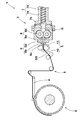
図1には、本実施形態のゴムストリップ製造装置1の概念図が断面図として示されている。図1に示されるように、本実施形態のゴムストリップ製造装置1は、ゴムGを予備成形して押し出すゴム押出機2と、ゴム押出機2から予備成形されて押し出されるゴムストリップGSを最終形状のゴムストリップGSに圧延成形する一対のカレンダーロール3とを含んでいる。カレンダーロール3から吐出されたゴムストリップGSは、例えば、コンベア4を含むアプリケータ5によって成形フォーマ6まで搬送されて巻き付けられることによりタイヤ用ゴム部材が製造される。
Hereinafter, embodiments of the present invention will be described with reference to the drawings.
FIG. 1 shows a conceptual diagram of the rubber strip manufacturing apparatus 1 of the present embodiment as a cross-sectional view. As shown in FIG. 1, the rubber strip manufacturing apparatus 1 of the present embodiment has a final shape of a
ゴム押出機2は、例えば、投入されたゴムGを混練りしながら一方向へ押すゴム押出機本体7と、ゴム押出機本体7の下流に配され、かつ定量的にゴムGを押し出すギヤポンプ8と、ギヤポンプ8から押し出されたゴムGを予備成形する押出ヘッド9とを備えている。
The
ゴム押出機本体7は、例えば、シリンダ7a内にスクリュ軸7bを収納した周知な構造を有している。スクリュ軸7bは、例えば、電動機(図示省略)により回転駆動されることによって、投入されたゴムGを混練しながらシリンダ7aの吐出口7cから吐出させる。
The rubber extruder main body 7 has, for example, a well-known structure in which the
ギヤポンプ8は、例えば、ケーシング8a内に一対の押出歯車8bが設けられた周知な構造の定容積押出機である。押出歯車8bは、例えば、電動機(図示省略)により回転駆動されることによって、混練りされたゴムGをケーシング8aから押出ヘッド9に吐出する。
The
押出ヘッド9は、例えば、ギヤポンプ8の下流側に交換可能に連結されたブロック状のヘッド本体9aと、このヘッド本体9aに交換自在に取り付けられるとともに予備成形口9cを開口させた口金9bとを備えている。従って、混練りされたゴムGは、押出ヘッド9によって、予備成形されたゴムストリップGSに成形される。
The
本実施形態の予備成形口9cは、横長矩形をなす比較的小さな開口である。また、ゴムGは、予備成形口9cとほぼ同じ矩形状の断面形状に成形されて外部に押し出され得る。このようなゴム押出機2は、比較的小出力のもので足りる。ただし、予備成形されたゴムストリップGSの断面形状は、上述のような矩形状に限定されるものではない。
The preformed opening 9c of the present embodiment is a relatively small opening forming a horizontally long rectangle. Further, the rubber G can be molded into a rectangular cross-sectional shape substantially the same as the preforming
本実施形態のカレンダーロール3は、例えば、上側に配される第1ロール10と、下側に配される第2ロール11とを含んでいる。第1ロール10及び第2ロール11は、実質的に回転軸が平行に配置されており、例えば、電動機(図示省略)により回転駆動されることによって、予備成形されたゴムストリップGSを最終形状のゴムストリップGSに成形している。
The
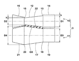
図2には、本実施形態のカレンダーロール3の正面図が示されている。図2に示されるように、本実施形態のカレンダーロール3は、例えば、形状が異なる第1ロール10と第2ロール11とが互いに対向して配されている。
FIG. 2 shows a front view of the
第1ロール10は、ゴムストリップGSに接触する圧延面12と、圧延面12よりロール軸方向の一方端13側の外側の第1支持面14と、圧延面12よりロール軸方向の他方端15側の外側の第2支持面16とを含んでいるのが望ましい。
The
第1ロール10の圧延面12は、例えば、ロール軸方向の一方端13から他方端15に向かって圧延面12の直径が漸減するテーパ面を有している。すなわち、第1ロール10の圧延面12の直径は、一方端13で最大直径D1となり、他方端15で最小直径D2となるのが望ましい。このような第1ロール10の圧延面12は、最小直径D2となる他方端15から順次、ゴムストリップGSが剥がれていくので、ゴムストリップGSが第1ロール10に不必要に粘着されることを抑制することができ、幅及び高さが均一であるゴムストリップGSを効率よく製造することができる。
The rolled
第1ロール10の第1支持面14は、例えば、略円筒形状を有している。第1ロール10の第2支持面16は、例えば、テーパ形状を有している。第1ロール10の第1支持面14及び第2支持面16は、ともに略円筒形状であってもよいし、ともにテーパ形状であってもよい。
The
第2ロール11は、ゴムストリップGSに接触する圧延面17と、圧延面17よりロール軸方向の一方端18側の外側の第3支持面19と、圧延面17よりロール軸方向の他方端20側の外側の第4支持面21とを含んでいるのが望ましい。
The
第2ロール11の圧延面17は、例えば、ロール軸方向の他方端20から一方端18に向かって圧延面17の直径が漸減するテーパ面を有している。すなわち、第2ロール11の圧延面17の直径は、一方端18で最小直径D3となり、他方端20で最大直径D4となるのが望ましい。このような第2ロール11の圧延面17は、最小直径D3となる一方端18から順次、ゴムストリップGSが剥がれていくので、ゴムストリップGSが第2ロール11に不必要に粘着されることを抑制することができ、幅及び高さが均一であるゴムストリップGSを効率よく製造することができる。
The rolled
第2ロール11の第3支持面19は、例えば、略円筒形状を有している。第2ロール11の第4支持面21は、例えば、テーパ形状を有している。第2ロール11の第3支持面19及び第4支持面21は、ともに略円筒形状であってもよいし、ともにテーパ形状であってもよい。
The
第2ロール11の圧延面17は、第1ロール10の圧延面12に対向しているのが望ましい。また、第1ロール10の圧延面12のテーパ面と第2ロール11の圧延面17のテーパ面とは、略平行に対向しているのが望ましい。このような第1ロール10と第2ロール11とは、第1ロール10と第2ロール11との間に間隙部22を形成することができる。
It is desirable that the rolled
ゴムストリップGSは、第1ロール10と第2ロール11との間で圧延されている。このため、間隙部22は、ゴムストリップGSの断面形状に近似しているのが望ましい。このような間隙部22を有するカレンダーロール3は、幅規制のためにナイフカット作業を要することなく、ゴムストリップGSを形成することができる。
The rubber strip GS is rolled between the
第1ロール10の圧延面12の最大直径D1は、好ましくは、第1ロール10の圧延面12の最小直径D2の105%以上である。第1ロール10の圧延面12の最大直径D1が最小直径D2の105%未満であると、第1ロール10の回転時、一方端13の表面速度と他方端15の表面速度との差が少なくなり、他方端15からゴムストリップGSが剥がれていかないおそれがある。
The maximum diameter D1 of the rolled
本実施形態では、第1ロール10の圧延面12のロール軸方向の一方端13での最大直径D1は、第1支持面14の一方端13での直径よりも小径である。また、第1ロール10の圧延面12のロール軸方向の他方端15での最小直径D2は、第2支持面16の他方端15での直径よりも小径である。第1ロール10の一方端13での圧延面12と第1支持面14との段差の高さhは、第1ロール10の他方端15での圧延面12と第2支持面16との段差の高さhに等しいのが望ましい。この高さhは、例えば、成形されるゴムストリップGSの厚さに応じて、適宜設定される。
In the present embodiment, the maximum diameter D1 of the rolled
第2ロール11の圧延面17の最大直径D4は、好ましくは、第2ロール11の圧延面17の最小直径D3の105%以上である。第2ロール11の圧延面17の最大直径D4が最小直径D3の105%未満であると、第2ロール11の回転時、一方端18の表面速度と他方端20の表面速度との差が少なくなり、一方端18からゴムストリップGSが剥がれていかないおそれがある。
The maximum diameter D4 of the rolled
第2ロール11の圧延面17の最大直径D4は、例えば、第1ロール10の圧延面12の最大直径D1よりも大きい。本実施形態では、第2ロール11の圧延面17の最小直径D3が、第1ロール10の圧延面12の最大直径D1よりも大きい。
The maximum diameter D4 of the rolled
このような第2ロール11は、直径が大きいことに伴い、ゴムストリップGSが粘着し易くなる。一方、第1ロール10は、一方端13及び他方端15に段差を有していることに伴い、ゴムストリップGSが粘着し易くなる。このため、第1ロール10及び第2ロール11に対するゴムストリップGSの粘着力は、略同一にコントロールされ得る。従って、カレンダーロール3は、ゴムストリップGSが第1ロール10又は第2ロール11に不必要に粘着されることを抑制することができ、幅及び高さが均一であるゴムストリップGSを効率よく製造することができる。
As the diameter of the
図3には、他の実施形態のカレンダーロール3Aの正面図が示されている。図3に示されるように、この実施形態のカレンダーロール3Aは、例えば、形状が同一の第1ロール23Aと第2ロール23Bとが互いに対向して配されている。
FIG. 3 shows a front view of the
第1ロール23Aは、例えば、ゴムストリップGSに接触する圧延面24Aと、圧延面24Aよりロール軸方向の一方端25A側の外側の第1支持面26Aと、圧延面24Aよりロール軸方向の他方端27A側の外側の第2支持面28Aとを含んでいる。第1ロール23Aの圧延面24Aは、例えば、ロール軸方向の一方端25Aから他方端27Aに向かって圧延面24Aの直径が漸減するテーパ面を有している。
The
第2ロール23Bは、第1ロール23Aと同一のものが用いられ、圧延面24Bと第1支持面26Bと第2支持面28Bとを含んでいる。第2ロール23Bは、ロール軸方向に対して、第1ロール23Aとは逆向きに配される。すなわち、第2ロール23Bの第1支持面26Bと第1ロール23Aの第2支持面28Aとが対向するとともに、第2ロール23Bの第2支持面28Bと第1ロール23Aの第1支持面26Aとが対向するように配されている。
As the
このようなカレンダーロール3Aは、第1ロール23Aと第2ロール23Bとに共通のロールを使用できるので、保守管理が容易になり、製造コストを低減することができる。
Since such a
以上、本発明の特に好ましい実施形態について詳述したが、本発明は図示の実施形態に限定されることなく、種々の態様に変形して実施し得る。 Although the particularly preferable embodiments of the present invention have been described in detail above, the present invention is not limited to the illustrated embodiments and can be modified into various embodiments.
図1に示されたゴムストリップ製造装置を用いてゴムストリップが製造され、製造時のゴムストリップトラブル発生率が評価された。また、ゴムストリップの均一性を評価するために、このゴムストリップを用いたサイズ235/45R18の空気入りタイヤが試作され、タイヤユニフォミティ性能が評価された。 A rubber strip was manufactured using the rubber strip manufacturing apparatus shown in FIG. 1, and the occurrence rate of rubber strip trouble during manufacturing was evaluated. Further, in order to evaluate the uniformity of the rubber strip, a pneumatic tire of size 235 / 45R18 using this rubber strip was prototyped, and the tire uniformity performance was evaluated.
<ゴムストリップトラブル発生率>
ゴムストリップ製造時におけるゴムストリップの切断、ローラへの粘着等、製造効率への影響があったトラブルの回数が測定された。結果は、比較例1のトラブル発生率を100とする指数であり、数値が小さい程、ゴムストリップトラブルが少ないことを示す。
<Rubber strip trouble occurrence rate>
The number of troubles that affected the manufacturing efficiency, such as cutting the rubber strip and sticking to the rollers during the manufacturing of the rubber strip, was measured. The result is an index with the trouble occurrence rate of Comparative Example 1 as 100, and the smaller the value, the less the rubber strip trouble.
<タイヤユニフォミティ性能>
各試供タイヤについて、コニシティが複数回測定され、それらの合計が求められた。結果は、比較例1のコニシティを100とする指数であり、数値が小さい程、タイヤユニフォミティが優れていることを示す。
<Tire uniformity performance>
For each test tire, the conicity was measured multiple times and the sum of them was calculated. The result is an index with the conicity of Comparative Example 1 as 100, and the smaller the value, the better the tire uniformity.
テストの結果が表1に示される。 The test results are shown in Table 1.

表1及び表2から明らかなように、実施例のゴムストリップは、比較例に比べて製造時のトラブル発生率が低く、タイヤユニフォミティが優れていることが確認された。 As is clear from Tables 1 and 2, it was confirmed that the rubber strips of the examples had a lower trouble occurrence rate during manufacturing and excellent tire uniformity as compared with the comparative examples.
次に、実施例のゴムストリップ製造装置を用いて、従来の比較例1に対して、カレンダーロールの回転速度を1.5倍の高速にした確認テストが行なわれた。 Next, using the rubber strip manufacturing apparatus of the example, a confirmation test was conducted in which the rotation speed of the calendar roll was 1.5 times faster than that of the conventional comparative example 1.
テストの結果が表2に示される。 The test results are shown in Table 2.
表2から明らかなように、実施例のゴムストリップ製造装置は、比較例に比べて、カレンダーロールの回転速度を高速にしても、製造時のトラブル発生率が低く、タイヤユニフォミティが優れていることが確認された。 As is clear from Table 2, the rubber strip manufacturing apparatus of the example has a low occurrence rate of troubles during manufacturing and excellent tire uniformity even if the rotation speed of the calendar roll is increased as compared with the comparative example. Was confirmed.
2 ゴム押出機
3 カレンダーロール
10 第1ロール
11 第2ロール
2
Claims (6)
第1ロールと第2ロールとを含み、
前記第1ロールの圧延面は、ロール軸方向の一方端から他方端に向かって前記圧延面の直径が漸減するテーパ面を有しており、
前記第2ロールの圧延面は、前記第1ロールの前記圧延面に対向し、かつ、ロール軸方向の前記他方端から前記一方端に向かって前記圧延面の直径が漸減するテーパ面を有しており、
前記第2ロールの前記圧延面の最大直径は、前記第1ロールの前記圧延面の最大直径よりも大きいことを特徴とするカレンダーロール。
A calender roll that rolls rubber strips extruded from a rubber extruder.
Including the first roll and the second roll
The rolled surface of the first roll has a tapered surface in which the diameter of the rolled surface gradually decreases from one end in the roll axis direction toward the other end.
The rolled surface of the second roll has a tapered surface that faces the rolled surface of the first roll and whose diameter of the rolled surface gradually decreases from the other end in the roll axis direction toward the one end. and,
A calendar roll characterized in that the maximum diameter of the rolled surface of the second roll is larger than the maximum diameter of the rolled surface of the first roll.
前記間隙部は、前記ゴムストリップの断面形状に近似している請求項1に記載のカレンダーロール。 The tapered surface of the first roll and the tapered surface of the second roll face each other substantially in parallel to form a gap between the first roll and the second roll.
The calendar roll according to claim 1, wherein the gap is close to the cross-sectional shape of the rubber strip.
前記第1支持面は、略円筒形状を有し、
前記第2支持面は、テーパ形状を有している請求項1又は2に記載のカレンダーロール。 The first roll includes a first support surface outside the one end side in the roll axis direction from the rolled surface of the first roll, and the other end side in the roll axis direction from the rolled surface of the first roll. Including the outer second support surface
The first support surface has a substantially cylindrical shape and has a substantially cylindrical shape.
The calendar roll according to claim 1 or 2, wherein the second support surface has a tapered shape .
請求項1乃至5のいずれかに記載のカレンダーロールと前記ゴム押出機とを含むことを特徴とするゴムストリップ製造装置。 It is a rubber strip manufacturing equipment
A rubber strip manufacturing apparatus comprising the calendar roll according to any one of claims 1 to 5 and the rubber extruder.
Priority Applications (1)
| Application Number | Priority Date | Filing Date | Title |
|---|---|---|---|
| JP2016089594A JP6790439B2 (en) | 2016-04-27 | 2016-04-27 | Calender roll and rubber strip manufacturing equipment |
Applications Claiming Priority (1)
| Application Number | Priority Date | Filing Date | Title |
|---|---|---|---|
| JP2016089594A JP6790439B2 (en) | 2016-04-27 | 2016-04-27 | Calender roll and rubber strip manufacturing equipment |
Publications (2)
| Publication Number | Publication Date |
|---|---|
| JP2017196804A JP2017196804A (en) | 2017-11-02 |
| JP6790439B2 true JP6790439B2 (en) | 2020-11-25 |
Family
ID=60238599
Family Applications (1)
| Application Number | Title | Priority Date | Filing Date |
|---|---|---|---|
| JP2016089594A Expired - Fee Related JP6790439B2 (en) | 2016-04-27 | 2016-04-27 | Calender roll and rubber strip manufacturing equipment |
Country Status (1)
| Country | Link |
|---|---|
| JP (1) | JP6790439B2 (en) |
-
2016
- 2016-04-27 JP JP2016089594A patent/JP6790439B2/en not_active Expired - Fee Related
Also Published As
| Publication number | Publication date |
|---|---|
| JP2017196804A (en) | 2017-11-02 |
Similar Documents
| Publication | Publication Date | Title |
|---|---|---|
| JPH06262663A (en) | Extruding device and method for unvulcanized rubber mixture | |
| EP3473420B1 (en) | Device and method for manufacturing multiple layer rubber strip | |
| EP1634690B1 (en) | Apparatus for producing a rubber strip | |
| JP3621879B2 (en) | Rubber strip manufacturing equipment | |
| JP6790439B2 (en) | Calender roll and rubber strip manufacturing equipment | |
| JP6763192B2 (en) | Calendar roll and rubber strip manufacturing equipment | |
| JP6699326B2 (en) | Calender roll and rubber strip manufacturing equipment | |
| CN104275795A (en) | Rubber component manufacturing apparatus | |
| KR20120095041A (en) | Vacuum dough noodle making machine | |
| CN105828629B (en) | Advanced gum formation | |
| JP2005238799A (en) | Device and method for molding rubber strip material for tire production and method for producing tire | |
| JP2013107370A (en) | Device and method for manufacturing rubber member | |
| WO2007046295A1 (en) | Pneumatic tire, tire molding apparatus and method of molding | |
| CN207615388U (en) | Mold for manufacturing plank and its die face | |
| EP3508324B1 (en) | Co-extrusion plant and method | |
| US20080265456A1 (en) | Method and System for Extruding Rubber Strip for Tire Constitutive Members | |
| EP2633984B1 (en) | Molding device and molding method for tire component | |
| JP2018030345A (en) | Production device for rubber member, and manufacturing method for pneumatic tire | |
| JP5881940B2 (en) | Tire manufacturing apparatus and manufacturing method | |
| CN215586409U (en) | Material extrusion forming equipment | |
| JP2015189159A (en) | Die plate for rubber extruder, rubber extrusion method and tire production method | |
| JP2014054804A (en) | Apparatus and method for producing rubber strip | |
| JP2019081288A (en) | Method of manufacturing tire rubber member | |
| CN216088565U (en) | Round steamed bun kneading and shaping structure | |
| JP2004249517A (en) | Extruder for thin-walled rubber and extrusion method using it |
Legal Events
| Date | Code | Title | Description |
|---|---|---|---|
| A621 | Written request for application examination |
Free format text: JAPANESE INTERMEDIATE CODE: A621 Effective date: 20190228 |
|
| A977 | Report on retrieval |
Free format text: JAPANESE INTERMEDIATE CODE: A971007 Effective date: 20200117 |
|
| A131 | Notification of reasons for refusal |
Free format text: JAPANESE INTERMEDIATE CODE: A131 Effective date: 20200303 |
|
| A521 | Request for written amendment filed |
Free format text: JAPANESE INTERMEDIATE CODE: A523 Effective date: 20200410 |
|
| TRDD | Decision of grant or rejection written | ||
| A01 | Written decision to grant a patent or to grant a registration (utility model) |
Free format text: JAPANESE INTERMEDIATE CODE: A01 Effective date: 20201006 |
|
| A61 | First payment of annual fees (during grant procedure) |
Free format text: JAPANESE INTERMEDIATE CODE: A61 Effective date: 20201019 |
|
| R150 | Certificate of patent or registration of utility model |
Ref document number: 6790439 Country of ref document: JP Free format text: JAPANESE INTERMEDIATE CODE: R150 |
|
| LAPS | Cancellation because of no payment of annual fees |