JP3621879B2 - Rubber strip manufacturing equipment - Google Patents
Rubber strip manufacturing equipment Download PDFInfo
- Publication number
- JP3621879B2 JP3621879B2 JP2000322887A JP2000322887A JP3621879B2 JP 3621879 B2 JP3621879 B2 JP 3621879B2 JP 2000322887 A JP2000322887 A JP 2000322887A JP 2000322887 A JP2000322887 A JP 2000322887A JP 3621879 B2 JP3621879 B2 JP 3621879B2
- Authority
- JP
- Japan
- Prior art keywords
- rubber
- width
- rubber strip
- screw
- internal pressure
- Prior art date
- Legal status (The legal status is an assumption and is not a legal conclusion. Google has not performed a legal analysis and makes no representation as to the accuracy of the status listed.)
- Expired - Lifetime
Links
Images


Classifications
-
- B—PERFORMING OPERATIONS; TRANSPORTING
- B29—WORKING OF PLASTICS; WORKING OF SUBSTANCES IN A PLASTIC STATE IN GENERAL
- B29C—SHAPING OR JOINING OF PLASTICS; SHAPING OF MATERIAL IN A PLASTIC STATE, NOT OTHERWISE PROVIDED FOR; AFTER-TREATMENT OF THE SHAPED PRODUCTS, e.g. REPAIRING
- B29C48/00—Extrusion moulding, i.e. expressing the moulding material through a die or nozzle which imparts the desired form; Apparatus therefor
- B29C48/25—Component parts, details or accessories; Auxiliary operations
- B29C48/30—Extrusion nozzles or dies
- B29C48/305—Extrusion nozzles or dies having a wide opening, e.g. for forming sheets
- B29C48/31—Extrusion nozzles or dies having a wide opening, e.g. for forming sheets being adjustable, i.e. having adjustable exit sections
-
- B—PERFORMING OPERATIONS; TRANSPORTING
- B29—WORKING OF PLASTICS; WORKING OF SUBSTANCES IN A PLASTIC STATE IN GENERAL
- B29C—SHAPING OR JOINING OF PLASTICS; SHAPING OF MATERIAL IN A PLASTIC STATE, NOT OTHERWISE PROVIDED FOR; AFTER-TREATMENT OF THE SHAPED PRODUCTS, e.g. REPAIRING
- B29C48/00—Extrusion moulding, i.e. expressing the moulding material through a die or nozzle which imparts the desired form; Apparatus therefor
- B29C48/03—Extrusion moulding, i.e. expressing the moulding material through a die or nozzle which imparts the desired form; Apparatus therefor characterised by the shape of the extruded material at extrusion
- B29C48/07—Flat, e.g. panels
- B29C48/08—Flat, e.g. panels flexible, e.g. films
-
- B—PERFORMING OPERATIONS; TRANSPORTING
- B29—WORKING OF PLASTICS; WORKING OF SUBSTANCES IN A PLASTIC STATE IN GENERAL
- B29C—SHAPING OR JOINING OF PLASTICS; SHAPING OF MATERIAL IN A PLASTIC STATE, NOT OTHERWISE PROVIDED FOR; AFTER-TREATMENT OF THE SHAPED PRODUCTS, e.g. REPAIRING
- B29C48/00—Extrusion moulding, i.e. expressing the moulding material through a die or nozzle which imparts the desired form; Apparatus therefor
- B29C48/03—Extrusion moulding, i.e. expressing the moulding material through a die or nozzle which imparts the desired form; Apparatus therefor characterised by the shape of the extruded material at extrusion
- B29C48/12—Articles with an irregular circumference when viewed in cross-section, e.g. window profiles
-
- B—PERFORMING OPERATIONS; TRANSPORTING
- B29—WORKING OF PLASTICS; WORKING OF SUBSTANCES IN A PLASTIC STATE IN GENERAL
- B29C—SHAPING OR JOINING OF PLASTICS; SHAPING OF MATERIAL IN A PLASTIC STATE, NOT OTHERWISE PROVIDED FOR; AFTER-TREATMENT OF THE SHAPED PRODUCTS, e.g. REPAIRING
- B29C48/00—Extrusion moulding, i.e. expressing the moulding material through a die or nozzle which imparts the desired form; Apparatus therefor
- B29C48/25—Component parts, details or accessories; Auxiliary operations
- B29C48/255—Flow control means, e.g. valves
- B29C48/2556—Flow control means, e.g. valves provided in or in the proximity of dies
-
- B—PERFORMING OPERATIONS; TRANSPORTING
- B29—WORKING OF PLASTICS; WORKING OF SUBSTANCES IN A PLASTIC STATE IN GENERAL
- B29C—SHAPING OR JOINING OF PLASTICS; SHAPING OF MATERIAL IN A PLASTIC STATE, NOT OTHERWISE PROVIDED FOR; AFTER-TREATMENT OF THE SHAPED PRODUCTS, e.g. REPAIRING
- B29C48/00—Extrusion moulding, i.e. expressing the moulding material through a die or nozzle which imparts the desired form; Apparatus therefor
- B29C48/25—Component parts, details or accessories; Auxiliary operations
- B29C48/92—Measuring, controlling or regulating
-
- B—PERFORMING OPERATIONS; TRANSPORTING
- B29—WORKING OF PLASTICS; WORKING OF SUBSTANCES IN A PLASTIC STATE IN GENERAL
- B29C—SHAPING OR JOINING OF PLASTICS; SHAPING OF MATERIAL IN A PLASTIC STATE, NOT OTHERWISE PROVIDED FOR; AFTER-TREATMENT OF THE SHAPED PRODUCTS, e.g. REPAIRING
- B29C2948/00—Indexing scheme relating to extrusion moulding
- B29C2948/92—Measuring, controlling or regulating
- B29C2948/92504—Controlled parameter
- B29C2948/92609—Dimensions
- B29C2948/92628—Width or height
-
- B—PERFORMING OPERATIONS; TRANSPORTING
- B29—WORKING OF PLASTICS; WORKING OF SUBSTANCES IN A PLASTIC STATE IN GENERAL
- B29C—SHAPING OR JOINING OF PLASTICS; SHAPING OF MATERIAL IN A PLASTIC STATE, NOT OTHERWISE PROVIDED FOR; AFTER-TREATMENT OF THE SHAPED PRODUCTS, e.g. REPAIRING
- B29C2948/00—Indexing scheme relating to extrusion moulding
- B29C2948/92—Measuring, controlling or regulating
- B29C2948/92504—Controlled parameter
- B29C2948/92609—Dimensions
- B29C2948/92647—Thickness
-
- B—PERFORMING OPERATIONS; TRANSPORTING
- B29—WORKING OF PLASTICS; WORKING OF SUBSTANCES IN A PLASTIC STATE IN GENERAL
- B29C—SHAPING OR JOINING OF PLASTICS; SHAPING OF MATERIAL IN A PLASTIC STATE, NOT OTHERWISE PROVIDED FOR; AFTER-TREATMENT OF THE SHAPED PRODUCTS, e.g. REPAIRING
- B29C2948/00—Indexing scheme relating to extrusion moulding
- B29C2948/92—Measuring, controlling or regulating
- B29C2948/92504—Controlled parameter
- B29C2948/92809—Particular value claimed
-
- B—PERFORMING OPERATIONS; TRANSPORTING
- B29—WORKING OF PLASTICS; WORKING OF SUBSTANCES IN A PLASTIC STATE IN GENERAL
- B29C—SHAPING OR JOINING OF PLASTICS; SHAPING OF MATERIAL IN A PLASTIC STATE, NOT OTHERWISE PROVIDED FOR; AFTER-TREATMENT OF THE SHAPED PRODUCTS, e.g. REPAIRING
- B29C2948/00—Indexing scheme relating to extrusion moulding
- B29C2948/92—Measuring, controlling or regulating
- B29C2948/92819—Location or phase of control
- B29C2948/92857—Extrusion unit
- B29C2948/92904—Die; Nozzle zone
-
- B—PERFORMING OPERATIONS; TRANSPORTING
- B29—WORKING OF PLASTICS; WORKING OF SUBSTANCES IN A PLASTIC STATE IN GENERAL
- B29C—SHAPING OR JOINING OF PLASTICS; SHAPING OF MATERIAL IN A PLASTIC STATE, NOT OTHERWISE PROVIDED FOR; AFTER-TREATMENT OF THE SHAPED PRODUCTS, e.g. REPAIRING
- B29C2948/00—Indexing scheme relating to extrusion moulding
- B29C2948/92—Measuring, controlling or regulating
- B29C2948/92819—Location or phase of control
- B29C2948/92942—Moulded article
-
- B—PERFORMING OPERATIONS; TRANSPORTING
- B29—WORKING OF PLASTICS; WORKING OF SUBSTANCES IN A PLASTIC STATE IN GENERAL
- B29C—SHAPING OR JOINING OF PLASTICS; SHAPING OF MATERIAL IN A PLASTIC STATE, NOT OTHERWISE PROVIDED FOR; AFTER-TREATMENT OF THE SHAPED PRODUCTS, e.g. REPAIRING
- B29C2948/00—Indexing scheme relating to extrusion moulding
- B29C2948/92—Measuring, controlling or regulating
- B29C2948/92819—Location or phase of control
- B29C2948/92961—Auxiliary unit, e.g. for external melt filtering, re-combining or transfer between units
-
- B—PERFORMING OPERATIONS; TRANSPORTING
- B29—WORKING OF PLASTICS; WORKING OF SUBSTANCES IN A PLASTIC STATE IN GENERAL
- B29K—INDEXING SCHEME ASSOCIATED WITH SUBCLASSES B29B, B29C OR B29D, RELATING TO MOULDING MATERIALS OR TO MATERIALS FOR MOULDS, REINFORCEMENTS, FILLERS OR PREFORMED PARTS, e.g. INSERTS
- B29K2021/00—Use of unspecified rubbers as moulding material
Description
【0001】
【発明の属する技術分野】
本発明は、仕上げ厚さT0が0.3〜1.5mmかつ仕上げ巾W0が5〜50mmの薄いゴムストリップを、厚さだけでなく巾を安定して形成することができ、ナイフカットによるゴムストリップの巾出し作業を排除しうるゴムストリップの製造装置に関する。
【0002】
【従来の技術、及び発明が解決しようとする課題】
例えば、空気入りタイヤでは、各部位における要求特性が異なるため、トレッドゴム、サイドウォールゴム、クリンチゴム、インナーライナゴムなど異なる配合かつ断面形状の種々のゴム部材によって構成されている。
【0003】
そして、近年、例えば図7に略示する如く、長尺状の未加硫のゴムストリップGを用い、これを螺旋状に重ねて巻き付けることによって、所望の仕上げ断面形状Yに近いゴム部材Bを、例えばドラム上で直接形成することが提案されている。なお同図には、ゴム部材Bがトレッドゴムである場合を例示している。
【0004】
このゴムストリップ巻回方式では、ゴム部材Bの表面に生じる鋸歯状の段差Cを減じるために、ゴムストリップGとして、仕上げ厚さを0.3〜1.5mmの範囲かつ仕上げ巾を5〜50mmの範囲とした非常に薄いものを使用することが好ましい。
【0005】
他方、このような薄いゴムストリップGの形成には、一般に、ゴム押出し機本体の吐出口の近傍に、上下のカレンダーロールを配することにより、吐出されたゴムをシート状に圧延成形するローラヘッド押出装置が広く使用されている。
【0006】
しかしこのものは、安定した厚さのものを得ることができる反面、巾寸法にはバラツキが生じ、そのままではゴム部材形成のために用いることは難しい。従って、従来、カレンダーロールによって圧延されたゴムストリップには、その両側縁をナイフカットし、所望の巾に仕上げる巾出し作業が必要となり、生産性の低下を招いていた。
【0007】
そこで本発明は、ゴム押出し機本体の前端にダイプレートを有する押出しヘッドを設け、ゴムを予成形してローラヘッドに送り込むとともに、前記ダイプレートの成形口の寸法やゴム押出し機本体の押出圧等を規制することを基本として、ナイフカットによる巾出し作業を施すことなく、薄いゴムストリップを安定した巾及び厚さを有して圧延成形することができ、生産性を向上しうるゴムストリップの製造装置の提供を目的としている。
【0008】
【課題を解決するための手段】
前記目的を達成するために、本願請求項1の発明は、スクリューにより吐出口からゴムを吐出するゴム押出し機本体、
該ゴム押出し機本体に後端が連結されるヘッド本体と、このヘッド本体の前端に取付き前記吐出口からのゴムを予成形して押し出す成形口を有するダイプレートとを具えた押出しヘッド、
及び前記成形口の近傍に配されかつ該成形口から押し出された予成形ゴムストリッブを仕上げ厚さT0が0.3〜1.5mmかつ仕上げ巾W0が5〜50mmのゴムストリップに調厚する上下のカレンダロールを有するローラヘッドを具え、
前記ヘッド本体は、ゴム押出し機本体とダイプレートとを結び該ダイプレートに向かって断面形状が円形から横長偏平に滑らかに変化する変化部を有する案内流路を具えるとともに、
以下の関係を充足することを特徴としている。
W2<W1+0.2×L −−−▲1▼
WA<W2 −−−▲2▼
0.7×W0≦WA≦1.0×W0 −−−▲3▼
1.5×T0≦TA≦10×T0 −−−▲4▼
P>40kgf/cm2 −−−▲5▼
式中、
Lは、前記変化部の軸心方向の長さ、
W1は、前記変化部の上流側端における開口の巾、
W2は、前記変化部の下流側端における開口の巾、
WAは、前記成形口の巾、
TAは、前記成形口の高さ、
Pは、前記スクリューの前端と前記変化部との間の流路部分内の内圧、
である。
【0009】
また請求項2の発明では、前記スクリューの前端と前記変化部との間の流路部分内に、この流路部分の断面積を絞ることにより前記内圧Pを前記範囲に高める絞り金具を着脱自在に配したことを特徴としている。
【0010】
また請求項3の発明では、前記ゴム押出し機本体は、前記内圧Pを測定する圧力センサを含み、この圧力センサの出力信号によって前記スクリューの回転数を調整し前記内圧Pを安定化する制御手段を具えることを特徴としている。
【0011】
【発明の実施の形態】
以下、本発明の実施の一形態を、図示例とともに説明する。
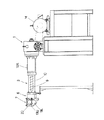
図1は、本発明のゴムストリップの製造装置を概念的に示す側面図、図2、3は、その主要部を拡大して示すゴムストリップの厚さ方向及び巾方向の断面図である。
【0012】
図において、ゴムストリップの製造装置1(以下、製造装置1という)は、吐出口2からゴムを吐出するゴム押出し機本体3と、このゴム押出し機本体3に連結され前記吐出口2からのゴムを予成形して成形口5から押し出す押出しヘッド6と、前記成形口5の近傍に配されこの成形口5からの予成形ゴムストリッブGpを調厚することにより所望の仕上げ厚さT0及び仕上げ巾W0のゴムストリップGに仕上げるローラヘッド7とを具えている。
【0013】
なお本発明の製造装置1では、図4に示すように、前記仕上げ厚さT0を0.3〜1.5mm、かつ仕上げ巾W0を5〜50mmとした薄厚のゴムストリップGを形成するために使用される。
【0014】
前記ゴム押出し機本体3は、スクリュー9を収納しかつゴム投入口10Aが設けられたシリンダ10を具え、電動機Mにより前記スクリュー9を駆動させることによって、投入されるゴムを混練しながらシリンダ10前端で開口する吐出口2(図2、3に示す)から押出す周知の構造を有している。
【0015】
なお、前記吐出口2は、前記シリンダ10の内腔10Hと同径な円形状をなし、また前記スクリュー9の前端がこの吐出口2から控えて終端することにより、このスクリュー9の前端と吐出口2との間にゴム溜まり部Jが形成されている。
【0016】
又前記押出しヘッド6は、図2、3に示すように、前記シリンダ10前端のフランジ部10Bに後端が連結されるブロック状のヘッド本体11と、このヘッド本体11の前端に交換自在に取り付くダイプレート12とを具え、該ダイプレート12には、前記吐出口2からのゴムを予成形する成形口5を形成している。この成形口5では、ローラヘッド7による加工率を減じ、圧延成形する際の厚さや巾のバラツキを減じることを目的としており、従ってその形状及び寸法は、ゴムストリップGの所望の仕上がり形状及び寸法に合わせて設定することが必要である。
【0017】
又前記押出しヘッド6の内部には、前記吐出口2と成形口5との間を滑らかに継ぐゴム流路14が形成されており、該ゴム流路14では、その断面積S及び高さTが夫々下流側に向かって減少し、ゴムを絞るように押進させる。
【0018】
このゴム流路14は、前記ヘッド本体11を通る案内流路15と、ダイプレート12を通る成形流路16とから構成されており、このうち、前記案内流路15は、該ダイプレート12に向かって断面形状が円形から横長偏平に滑らかに変化する変化部15Aを少なくとも含む。本例では、この変化部15Aの上流側に、前記吐出口2と同径な円形状でのびる継ぎ部15Bを延設した場合を例示しているが、この継ぎ部15Bを排除し、変化部15Aが前記吐出口2に直接連なる如く構成することもできる。
【0019】
又前記成形流路16では、その断面積S及び高さTの変化の度合いが、前記変化部15Aにおける断面積S及び高さTの変化の度合いに比して、充分に小であり、必要な加工率を確保しつつゴム内の残留応力を緩和している。なお本例では、前記変化部15A及び成形流路16において、夫々、少なくとも高さTの変化の度合いを一定とした場合を例示している。
【0020】
次に、前記ローラヘッド7は、前記成形口5の近傍に配される上、下のカレンダーロール19U、19Lを有し、本例では、ホルダー20を介して前記押出しヘッド6に支持させた好ましい場合を例示している。なお例えば、ロールスタンドを用いて、ゴム押出し機本体3や押出しヘッド6から独立して設置することもできる。又前記上、下のカレンダーロール19U、19Lは、互いに同速度が一般的であるが、主に作業性を考えて若干のフリクションを付ける事もある。
【0021】
このように、本願の製造装置1では、いったん押出しヘッド6を用いて、横長偏平の予成形ゴムストリップGpを成形し、圧延成形における厚さや巾のバラツキが問題にならない程度に予加工を施した後、ローラヘッド7により最終形状に加工している。従って、寸法の精度および安定性が高まり、通常、圧延成形において必要とされていたナイフカットによる巾出し作業が不必要となるなど、製造効率を向上できる。又ゴムストリップGの製造やこれを用いたゴム製品の製造の自動化等に大きく貢献できる。
【0022】
又そのためには、
(1) 前記スクリュー9からの押出し圧力、即ちスクリュー9前端と前記変化部15Aとの間の流路部分17内での内圧Pを高める一方、前記ゴム流路14での寸法を規制し、これによって押出しバラツキを予成形ゴムストリップGpに反映し難くすること、及び
(2) 前記ゴムストリップGの仕上がり寸法に対して、成形口5の寸法を規制し、ローラヘッド7による圧延成形での加工率を減じること、
が極めて必要である。
【0023】
具体的には、前記図5にすように、前記変化部15Aの軸心方向の長さをL、前記変化部15Aの上流側端における開口の巾をW1、前記変化部15Aの下流側端における開口の巾をW2、前記成形口5の巾をWA、前記成形口5の高さをTAとした時、以下の関係を充足させることが必要である。
【0024】
W2<W1+0.2×L −−−▲1▼
WA<W2 −−−▲2▼
0.7×W0≦WA≦1.0×W0 −−−▲3▼
1.5×T0≦TA≦10.0×T0 −−−▲4▼
P>40kgf/cm2 −−−▲5▼
【0025】
ここで、変化部15Aでの前記巾W2が、W1+0.2×L以上に大きくなると、両端側へのゴム流れが悪くなり、巾方向の形状及び寸法の均一性が損なわれる。又成型口5での前記巾WAが、巾W2以上に大きくなる場合も同様に、両端側へのゴム流れが悪くなり、巾方向の形状及び寸法の均一性が損なわれる。
【0026】
又前記巾WAが、ゴムストリップGの仕上げ巾W0の0.7倍未満では、圧延による加工率が過大となり、ゴムストリップGの品質及び精度が不充分となる。特に、巾寸法の精度が不安定となり、ナイフカットによる巾出し作業が必要となってくる。従って、巾WAは、仕上げ巾W0の0.8〜0.9倍の範囲が好ましい。
【0027】
又成型口5の前記高さTAが、ゴムストリップの仕上げ厚さT0の1.5倍未満では、1.5mm以下のゴムストリップGを得るには、押出し時のゴム厚さが薄くなり過ぎ、ゴムストリップGに波打ちが生じるとともに厚さも不均一になりやすくなる。逆に、仕上げ厚さT0の10倍をこえると、圧延による加工率が過大となって、巾寸法を充分に安定化させることができなくなる。従って、厚さTAは、仕上げ厚さT0の3〜5倍の範囲が好ましい。
【0028】
又前記流路部分17内での内圧Pも重要であり、内圧Pが40kgf/cm2 (3922.66kPaに相当)以下に減じると、押出しバラツキが予成形ゴムストリップGpに反映しやすくなり、特に巾寸法がバラつくことから、従来のナイフカットによる巾出し作業が必要となってしまう。この内圧Pの上限は、ゴム焼けしない範囲で高い方が望ましく、従って、好ましくは、60kgf/cm2 以上が良い。
【0029】
なお本例では、前記内圧Pを前記範囲内で安定化するため、制御手段21を設けている。この制御手段21は、図2に示すように、前記シリンダ10に取り付き前記ゴム溜まり部Jのでの圧力を測定する圧力センサ22を含み、この圧力センサ22の出力信号によって前記電動機Mの回転数を調整、即ちスクリュー9の回転数を調整し前記内圧Pを安定化させる。
【0030】
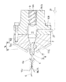
又前記内圧Pを前記範囲に高めるために、図6に示す如く、前記流路部分17内に、この流路部分17の断面積を絞る(減じる)リング状の絞り金具23を着脱自在に取り付けることができる。本例では、この絞り金具23が、前記流路部分17の周壁に設けた環状溝24に、填り合って保持される場合を例示する。
【0031】
該絞り金具23は、前記内圧Pを高める他、スクリュー9等による脈動などがゴム流路14側に伝達するのを阻止する効果も有し、ゴムストリップGの
押出しバラツキをいっそう低減することができる。なお絞り金具23の絞り部分の内径D1は、配合ゴムによって違いもあるが、前記内腔10Hの内径Dの0.5〜0.2倍が一般的に好ましい。
【0032】
以上、本発明の特に好ましい実施形態について詳述したが、本発明は図示の実施形態に限定されることなく、種々の態様に変形して実施しうる。
【0033】
【実施例】
図1〜3の構造を有する製造装置を用い表1の仕様でゴムストリップを形成し、その時の寸法バラツキの範囲を測定した。
【0034】
【表1】

薄いゴムストリップの形成において、仕上げ厚さT0及び仕上げ巾W0のバラツキを低く抑えうることが確認できた。
【0036】
【発明の効果】
叙上の如く、本発明のゴムストリップの製造装置は、ゴム押出し機本体の前端にダイプレートを有する押出しヘッドを設け、ゴムを予成形してローラヘッドに送り込むとともに、前記ダイプレートの成形口の寸法やゴム押出し機本体の押出圧等を規制しているため、ナイフカットによる巾出し作業を施すことなく、薄いゴムストリップを安定した巾及び厚さを有して形成することができる。
【図面の簡単な説明】
【図1】本発明の一実施例のゴムストリップの製造装置を概念的に示す側面図である。
【図2】その主要部を拡大して示す厚さ方向の断面図である。
【図3】その主要部を拡大して示す巾方向の断面図である。
【図4】仕上がり状態のゴムストリップを示す断面図である。
【図5】押出しに際してのゴムの形状変化を説明する斜視図である。
【図6】押出しヘッドの他の例を示す断面図である。
【図7】ゴムストリップを用いたコム製品の一例を示す断面図である。
【符号の説明】
2 吐出口
3 ゴム押出し機本体
5 成形口
6 押出しヘッド
7 ローラヘッド
9 スクリュー
11 ヘッド本体
12 ダイプレート
15 案内流路
15A 変化部
17 流路部分
19U、19L カレンダロール
21 制御手段
22 圧力センサ
23 絞り金具[0001]
BACKGROUND OF THE INVENTION
The present invention can stably form not only the thickness but also the width of a thin rubber strip having a finishing thickness T0 of 0.3 to 1.5 mm and a finishing width W0 of 5 to 50 mm. The present invention relates to a rubber strip manufacturing apparatus capable of eliminating strip stripping work.
[0002]
[Background Art and Problems to be Solved by the Invention]
For example, since the required characteristics in each part are different in a pneumatic tire, it is constituted by various rubber members having different compositions and cross-sectional shapes such as tread rubber, sidewall rubber, clinch rubber, and inner liner rubber.
[0003]
In recent years, for example, as schematically shown in FIG. 7, a long unvulcanized rubber strip G is used, and the rubber member B close to a desired finished cross-sectional shape Y is formed by spirally winding the strip. For example, it has been proposed to form directly on a drum. In the figure, the rubber member B is illustrated as a tread rubber.
[0004]
In this rubber strip winding method, in order to reduce the serrated step C generated on the surface of the rubber member B, the rubber strip G has a finished thickness in the range of 0.3 to 1.5 mm and a finished width of 5 to 50 mm. It is preferable to use a very thin material in the range described above.
[0005]
On the other hand, in order to form such a thin rubber strip G, in general, an upper and lower calendar rolls are arranged in the vicinity of the discharge port of the rubber extruder main body, so that the discharged rubber is rolled into a sheet shape. Extrusion equipment is widely used.
[0006]
However, while this can be obtained with a stable thickness, there is variation in the width dimension and it is difficult to use it as it is for forming a rubber member. Therefore, conventionally, a rubber strip rolled by a calender roll requires a drawing operation in which both side edges are knife-cut and finished to a desired width, resulting in a decrease in productivity.
[0007]
Therefore, the present invention provides an extrusion head having a die plate at the front end of the rubber extruder main body, pre-molds the rubber and feeds it to the roller head, and measures the dimensions of the die plate molding port, the extrusion pressure of the rubber extruder main body, The production of a rubber strip that can improve the productivity by rolling a thin rubber strip with a stable width and thickness without performing a drawing operation by knife cutting. The purpose is to provide a device.
[0008]
[Means for Solving the Problems]
In order to achieve the above object, the invention of claim 1 of the present application includes a rubber extruder main body that discharges rubber from a discharge port by a screw,
An extrusion head comprising: a head body having a rear end coupled to the rubber extruder body; and a die plate having a molding port for pre-molding and extruding rubber from the discharge port attached to the front end of the head body.
The upper and lower thicknesses of the pre-formed rubber strip disposed near the molding port and extruded from the molding port are adjusted to rubber strips having a finishing thickness T0 of 0.3 to 1.5 mm and a finishing width W0 of 5 to 50 mm. Comprising a roller head having a calendar roll;
The head body includes a guide channel having a changing portion that smoothly connects a rubber extruder body and a die plate, and a cross-sectional shape smoothly changes from a circular shape to a horizontally long shape toward the die plate,
It is characterized by satisfying the following relationship.
W2 <W1 + 0.2 × L --- <1>
WA <W2 ---- <2>
0.7 × W0 ≦ WA ≦ 1.0 × W0 --- <3>
1.5 × T0 ≦ TA ≦ 10 × T0 --- (4)
P> 40 kgf / cm 2 ---- <5>
Where
L is the axial length of the change part,
W1 is the width of the opening at the upstream end of the change part,
W2 is the width of the opening at the downstream end of the change part,
WA is the width of the molding port,
TA is the height of the molding port,
P is the internal pressure in the flow path part between the front end of the screw and the change part,
It is.
[0009]
According to a second aspect of the present invention, in the flow passage portion between the front end of the screw and the changing portion, a throttle fitting that raises the internal pressure P to the range by reducing the cross-sectional area of the flow passage portion is detachable. It is characterized by being arranged in.
[0010]
According to a third aspect of the present invention, the rubber extruder body includes a pressure sensor for measuring the internal pressure P, and the control means for stabilizing the internal pressure P by adjusting the number of rotations of the screw according to an output signal of the pressure sensor. It is characterized by comprising.
[0011]
DETAILED DESCRIPTION OF THE INVENTION
Hereinafter, an embodiment of the present invention will be described with reference to the drawings.
FIG. 1 is a side view conceptually showing an apparatus for manufacturing a rubber strip according to the present invention, and FIGS. 2 and 3 are sectional views in the thickness direction and width direction of the rubber strip showing an enlarged main portion thereof.
[0012]
In the figure, a rubber strip manufacturing apparatus 1 (hereinafter referred to as manufacturing apparatus 1) includes a
[0013]
In the manufacturing apparatus 1 of the present invention, as shown in FIG. 4, in order to form a thin rubber strip G having a finishing thickness T0 of 0.3 to 1.5 mm and a finishing width W0 of 5 to 50 mm. used.
[0014]
The rubber extruder
[0015]
The
[0016]
2 and 3, the
[0017]
A
[0018]
The
[0019]
Further, the degree of change in the cross-sectional area S and the height T of the
[0020]
Next, the
[0021]
As described above, in the manufacturing apparatus 1 of the present application, the pre-formed rubber strip Gp having a horizontally long shape is once formed by using the
[0022]
And for that,
(1) The extrusion pressure from the
Is extremely necessary.
[0023]
Specifically, as shown in FIG. 5, the axial length of the
[0024]
W2 <W1 + 0.2 × L --- <1>
WA <W2 ---- <2>
0.7 × W0 ≦ WA ≦ 1.0 × W0 --- <3>
1.5 × T0 ≦ TA ≦ 10.0 × T0 --- (4)
P> 40 kgf / cm 2 ---- <5>
[0025]
Here, if the width W2 at the changing
[0026]
If the width WA is less than 0.7 times the finishing width W0 of the rubber strip G, the processing rate by rolling becomes excessive, and the quality and accuracy of the rubber strip G become insufficient. In particular, the accuracy of the width dimension becomes unstable, and it is necessary to perform a drawing operation by knife cutting. Accordingly, the width WA is preferably in the range of 0.8 to 0.9 times the finishing width W0.
[0027]
If the height TA of the
[0028]
Also, the internal pressure P in the
[0029]
In this example, a control means 21 is provided to stabilize the internal pressure P within the range. As shown in FIG. 2, the control means 21 includes a
[0030]
Further, in order to increase the internal pressure P to the above range, as shown in FIG. 6, a ring-shaped
[0031]
In addition to increasing the internal pressure P, the throttle fitting 23 also has an effect of preventing pulsation caused by the
[0032]
As mentioned above, although especially preferable embodiment of this invention was explained in full detail, this invention is not limited to embodiment of illustration, It can deform | transform and implement in a various aspect.
[0033]
【Example】
A rubber strip was formed with the specifications shown in Table 1 using the manufacturing apparatus having the structure shown in FIGS. 1 to 3, and the range of dimensional variation at that time was measured.
[0034]
[Table 1]
It was confirmed that the variation in the finishing thickness T0 and the finishing width W0 can be kept low in forming the thin rubber strip.
[0036]
【The invention's effect】
As described above, the rubber strip manufacturing apparatus according to the present invention is provided with an extrusion head having a die plate at the front end of the rubber extruder body, pre-molds the rubber and feeds it to the roller head. Since the dimensions, the extrusion pressure of the rubber extruder main body, and the like are regulated, a thin rubber strip can be formed with a stable width and thickness without performing a drawing operation by knife cutting.
[Brief description of the drawings]
FIG. 1 is a side view conceptually showing a rubber strip manufacturing apparatus according to an embodiment of the present invention.
FIG. 2 is a cross-sectional view in the thickness direction showing an enlarged main portion thereof.
FIG. 3 is a cross-sectional view in the width direction showing an enlarged main part thereof.
FIG. 4 is a cross-sectional view showing a finished rubber strip.
FIG. 5 is a perspective view for explaining a change in the shape of rubber during extrusion.
FIG. 6 is a cross-sectional view showing another example of the extrusion head.
FIG. 7 is a cross-sectional view showing an example of a comb product using a rubber strip.
[Explanation of symbols]
2 Discharge
Claims (3)
該ゴム押出し機本体に後端が連結されるヘッド本体と、このヘッド本体の前端に取付き前記吐出口からのゴムを予成形して押し出す成形口を有するダイプレートとを具えた押出しヘッド、
及び前記成形口の近傍に配されかつ該成形口から押し出された予成形ゴムストリッブを仕上げ厚さT0が0.3〜1.5mmかつ仕上げ巾W0が5〜50mmのゴムストリップに調厚する上下のカレンダロールを有するローラヘッドを具え、
前記ヘッド本体は、ゴム押出し機本体とダイプレートとを結び該ダイプレートに向かって断面形状が円形から横長偏平に滑らかに変化する変化部を有する案内流路を具えるとともに、
以下の関係を充足することを特徴とするゴムストリップの製造装置。
W2<W1+0.2×L −−−▲1▼
WA<W2 −−−▲2▼
0.7×W0≦WA≦1.0×W0 −−−▲3▼
1.5×T0≦TA≦10×T0 −−−▲4▼
P>40kgf/cm2 −−−▲5▼
式中、
Lは、前記変化部の軸心方向の長さ、
W1は、前記変化部の上流側端における開口の巾、
W2は、前記変化部の下流側端における開口の巾、
WAは、前記成形口の巾、
TAは、前記成形口の高さ、
Pは、前記スクリューの前端と前記変化部との間の流路部分内の内圧、
である。Rubber extruder body that discharges rubber from the discharge port with a screw,
An extrusion head comprising: a head body having a rear end coupled to the rubber extruder body; and a die plate having a molding port that pre-molds and extrudes rubber from the discharge port attached to the front end of the head body.
The upper and lower thicknesses of the pre-formed rubber strip disposed near the molding port and extruded from the molding port are adjusted to rubber strips having a finishing thickness T0 of 0.3 to 1.5 mm and a finishing width W0 of 5 to 50 mm. Comprising a roller head having a calendar roll;
The head body includes a guide channel having a changing portion that smoothly connects a rubber extruder body and a die plate, and a cross-sectional shape smoothly changes from a circular shape to a horizontally long shape toward the die plate,
A rubber strip manufacturing apparatus satisfying the following relationship:
W2 <W1 + 0.2 × L --- <1>
WA <W2 ---- <2>
0.7 × W0 ≦ WA ≦ 1.0 × W0 --- <3>
1.5 × T0 ≦ TA ≦ 10 × T0 --- (4)
P> 40 kgf / cm 2 ---- <5>
Where
L is the axial length of the change part,
W1 is the width of the opening at the upstream end of the change part,
W2 is the width of the opening at the downstream end of the change part,
WA is the width of the molding port,
TA is the height of the molding port,
P is the internal pressure in the flow path part between the front end of the screw and the change part,
It is.
Priority Applications (4)
| Application Number | Priority Date | Filing Date | Title |
|---|---|---|---|
| JP2000322887A JP3621879B2 (en) | 2000-10-23 | 2000-10-23 | Rubber strip manufacturing equipment |
| US09/974,859 US6688872B2 (en) | 2000-10-23 | 2001-10-12 | Apparatus for making unvulcanized rubber tape |
| DE60143010T DE60143010D1 (en) | 2000-10-23 | 2001-10-19 | Device for producing an unvulcanized rubber band |
| EP01308887A EP1201397B1 (en) | 2000-10-23 | 2001-10-19 | Apparatus for making unvulcanised rubber tape |
Applications Claiming Priority (1)
| Application Number | Priority Date | Filing Date | Title |
|---|---|---|---|
| JP2000322887A JP3621879B2 (en) | 2000-10-23 | 2000-10-23 | Rubber strip manufacturing equipment |
Publications (2)
| Publication Number | Publication Date |
|---|---|
| JP2002127234A JP2002127234A (en) | 2002-05-08 |
| JP3621879B2 true JP3621879B2 (en) | 2005-02-16 |
Family
ID=18800682
Family Applications (1)
| Application Number | Title | Priority Date | Filing Date |
|---|---|---|---|
| JP2000322887A Expired - Lifetime JP3621879B2 (en) | 2000-10-23 | 2000-10-23 | Rubber strip manufacturing equipment |
Country Status (4)
| Country | Link |
|---|---|
| US (1) | US6688872B2 (en) |
| EP (1) | EP1201397B1 (en) |
| JP (1) | JP3621879B2 (en) |
| DE (1) | DE60143010D1 (en) |
Families Citing this family (14)
| Publication number | Priority date | Publication date | Assignee | Title |
|---|---|---|---|---|
| JP4721392B2 (en) * | 2003-04-04 | 2011-07-13 | 株式会社ブリヂストン | Rubber sheet manufacturing equipment |
| JP4547136B2 (en) * | 2003-07-16 | 2010-09-22 | 株式会社ブリヂストン | Tire and tire manufacturing method |
| US20050092365A1 (en) * | 2003-10-28 | 2005-05-05 | Rawes Godfrey D. | Extrusion assembly |
| JP4426937B2 (en) * | 2004-09-14 | 2010-03-03 | 住友ゴム工業株式会社 | Rubber strip manufacturing equipment |
| JP5297711B2 (en) * | 2008-07-18 | 2013-09-25 | 株式会社ブリヂストン | Rubber member molding apparatus and molding method |
| JP5364165B2 (en) * | 2009-08-25 | 2013-12-11 | 住友ゴム工業株式会社 | Rubber extrusion base |
| US20120318439A1 (en) * | 2009-12-22 | 2012-12-20 | Stefano Testi | Extrusion process and device for producing elastomeric compounds |
| CN102744858A (en) * | 2011-12-29 | 2012-10-24 | 青岛宏达塑胶总公司 | Plate extrusion addition type width adjustment apparatus |
| JP5735932B2 (en) * | 2012-06-07 | 2015-06-17 | 住友ゴム工業株式会社 | Rubber strip manufacturing method and manufacturing apparatus |
| FR3000423B1 (en) * | 2012-12-27 | 2015-02-27 | Michelin & Cie | METHOD AND DEVICE FOR REGULATING AN EXTRUSION DEVICE |
| JP2016002712A (en) * | 2014-06-17 | 2016-01-12 | 住友ゴム工業株式会社 | Production device for rubber member and method for producing the same |
| ITUB20161171A1 (en) * | 2016-02-29 | 2017-08-29 | Flon Project S R L | A modeling device for obtaining a bi-oriented PTFE tape or semi-finished products. |
| JP7198151B2 (en) * | 2019-05-17 | 2022-12-28 | Toyo Tire株式会社 | Molding method and molding apparatus for belt-shaped rubber member |
| DE102022200817A1 (en) * | 2022-01-25 | 2023-07-27 | Continental Reifen Deutschland Gmbh | Device and computer-implemented method for controlling an extrusion system, extrusion system and computer-readable storage medium |
Family Cites Families (11)
| Publication number | Priority date | Publication date | Assignee | Title |
|---|---|---|---|---|
| DE2028064A1 (en) * | 1970-06-08 | 1971-12-16 | Troester Maschf Paul | Screw press for molding preplasticized elastomers or thermoplastics |
| US3890078A (en) * | 1972-01-31 | 1975-06-17 | Industrial Nucleonics Corp | Noninteracting extruder control |
| US3871810A (en) * | 1972-11-20 | 1975-03-18 | Uniroyal Inc | Extruder and roller-die combination |
| US4124346A (en) * | 1976-04-07 | 1978-11-07 | The Goodyear Tire & Rubber Company | Extruder die arrangement |
| JPS5418865A (en) * | 1977-07-14 | 1979-02-13 | Kobe Steel Ltd | Extrusion molding of synthetic resin and die therefor |
| SU1224161A1 (en) * | 1984-08-02 | 1986-04-15 | Научно-исследовательский институт крупногабаритных шин | Extrusion head for extrusion moulding of high-viscosity rubber mix web |
| US5179521A (en) * | 1989-03-29 | 1993-01-12 | Quantum Chemical Corporation | System and method for controlling continuous mixer with melt pump |
| FR2673141B1 (en) | 1991-02-21 | 1994-09-02 | Aerospatiale | ADJUSTABLE DIE WITH ROTATING ROLLERS FOR THE PRODUCTION OF A BELT WITH INCLINED EDGES. |
| US5221541A (en) * | 1991-09-11 | 1993-06-22 | Bridgestone/Firestone, Inc. | Extruder head for elastomeric material |
| US5176925A (en) * | 1992-03-25 | 1993-01-05 | Amphenol Corporation | Extrusion die with static mixer insert |
| JP3322648B2 (en) | 1999-03-03 | 2002-09-09 | 住友ゴム工業株式会社 | Rubber conveying device and rubber molding device using the same |
-
2000
- 2000-10-23 JP JP2000322887A patent/JP3621879B2/en not_active Expired - Lifetime
-
2001
- 2001-10-12 US US09/974,859 patent/US6688872B2/en not_active Expired - Lifetime
- 2001-10-19 DE DE60143010T patent/DE60143010D1/en not_active Expired - Lifetime
- 2001-10-19 EP EP01308887A patent/EP1201397B1/en not_active Expired - Lifetime
Also Published As
| Publication number | Publication date |
|---|---|
| EP1201397B1 (en) | 2010-09-08 |
| US20020048615A1 (en) | 2002-04-25 |
| JP2002127234A (en) | 2002-05-08 |
| DE60143010D1 (en) | 2010-10-21 |
| EP1201397A2 (en) | 2002-05-02 |
| US6688872B2 (en) | 2004-02-10 |
| EP1201397A3 (en) | 2002-12-04 |
Similar Documents
| Publication | Publication Date | Title |
|---|---|---|
| JP3621879B2 (en) | Rubber strip manufacturing equipment | |
| EP1279486A2 (en) | Production of shaped rubber body | |
| JPH0377624U (en) | ||
| US7494335B2 (en) | Apparatus for producing rubber strip | |
| EP2033763B1 (en) | Method of manufacturing a thin rubber member, rubber roller, and method of rolling a rubber | |
| EP2886295B1 (en) | Rubber strip manufacturing device and manufacturing method | |
| US6190595B1 (en) | Extrusion arrangement | |
| US6761841B2 (en) | Method for extruding tire rubber material | |
| EP1647390A2 (en) | Double flow channel for an extruder head | |
| JP6560031B2 (en) | Rubber sheet manufacturing apparatus and manufacturing method | |
| EP1211049B1 (en) | Method and apparatus for rubber extrusion | |
| EP3650195A1 (en) | Screw extruder with rollers | |
| US8192663B2 (en) | Method for manufacturing a tyre and extruder for producing a semi-finished elastomeric product | |
| JPH0475126B2 (en) | ||
| JP2012081716A (en) | Rubber extruder | |
| JP2000351145A (en) | Roller head rubber extrusion apparatus | |
| JP6763192B2 (en) | Calendar roll and rubber strip manufacturing equipment | |
| JP3983064B2 (en) | Rubber sheet molding equipment | |
| JP2004249517A (en) | Extruder for thin-walled rubber and extrusion method using it | |
| JPH08281770A (en) | Expansion die | |
| JP4068400B2 (en) | Screw for extruder | |
| JP2003326586A (en) | Method for extrusion molding of rubber sheet containing short fiber, and extrusion molding device | |
| JP6699326B2 (en) | Calender roll and rubber strip manufacturing equipment | |
| JPH05104605A (en) | Manufacture of weatherstrip | |
| JP6862746B2 (en) | Manufacturing method of extruded rubber |
Legal Events
| Date | Code | Title | Description |
|---|---|---|---|
| TRDD | Decision of grant or rejection written | ||
| A01 | Written decision to grant a patent or to grant a registration (utility model) |
Free format text: JAPANESE INTERMEDIATE CODE: A01 Effective date: 20041109 |
|
| A61 | First payment of annual fees (during grant procedure) |
Free format text: JAPANESE INTERMEDIATE CODE: A61 Effective date: 20041119 |
|
| R150 | Certificate of patent or registration of utility model |
Free format text: JAPANESE INTERMEDIATE CODE: R150 Ref document number: 3621879 Country of ref document: JP Free format text: JAPANESE INTERMEDIATE CODE: R150 |
|
| FPAY | Renewal fee payment (event date is renewal date of database) |
Free format text: PAYMENT UNTIL: 20071126 Year of fee payment: 3 |
|
| FPAY | Renewal fee payment (event date is renewal date of database) |
Free format text: PAYMENT UNTIL: 20081126 Year of fee payment: 4 |
|
| R250 | Receipt of annual fees |
Free format text: JAPANESE INTERMEDIATE CODE: R250 |
|
| FPAY | Renewal fee payment (event date is renewal date of database) |
Free format text: PAYMENT UNTIL: 20091126 Year of fee payment: 5 |
|
| R250 | Receipt of annual fees |
Free format text: JAPANESE INTERMEDIATE CODE: R250 |
|
| FPAY | Renewal fee payment (event date is renewal date of database) |
Free format text: PAYMENT UNTIL: 20091126 Year of fee payment: 5 |
|
| FPAY | Renewal fee payment (event date is renewal date of database) |
Free format text: PAYMENT UNTIL: 20101126 Year of fee payment: 6 |
|
| R250 | Receipt of annual fees |
Free format text: JAPANESE INTERMEDIATE CODE: R250 |
|
| FPAY | Renewal fee payment (event date is renewal date of database) |
Free format text: PAYMENT UNTIL: 20111126 Year of fee payment: 7 |
|
| R250 | Receipt of annual fees |
Free format text: JAPANESE INTERMEDIATE CODE: R250 |
|
| FPAY | Renewal fee payment (event date is renewal date of database) |
Free format text: PAYMENT UNTIL: 20121126 Year of fee payment: 8 |
|
| R250 | Receipt of annual fees |
Free format text: JAPANESE INTERMEDIATE CODE: R250 |
|
| FPAY | Renewal fee payment (event date is renewal date of database) |
Free format text: PAYMENT UNTIL: 20121126 Year of fee payment: 8 |
|
| FPAY | Renewal fee payment (event date is renewal date of database) |
Free format text: PAYMENT UNTIL: 20131126 Year of fee payment: 9 |
|
| R250 | Receipt of annual fees |
Free format text: JAPANESE INTERMEDIATE CODE: R250 |
|
| R250 | Receipt of annual fees |
Free format text: JAPANESE INTERMEDIATE CODE: R250 |
|
| R250 | Receipt of annual fees |
Free format text: JAPANESE INTERMEDIATE CODE: R250 |
|
| R250 | Receipt of annual fees |
Free format text: JAPANESE INTERMEDIATE CODE: R250 |
|
| R250 | Receipt of annual fees |
Free format text: JAPANESE INTERMEDIATE CODE: R250 |
|
| R250 | Receipt of annual fees |
Free format text: JAPANESE INTERMEDIATE CODE: R250 |
|
| EXPY | Cancellation because of completion of term |