JP6786239B2 - Cushioning material and packing body - Google Patents
Cushioning material and packing body Download PDFInfo
- Publication number
- JP6786239B2 JP6786239B2 JP2016069287A JP2016069287A JP6786239B2 JP 6786239 B2 JP6786239 B2 JP 6786239B2 JP 2016069287 A JP2016069287 A JP 2016069287A JP 2016069287 A JP2016069287 A JP 2016069287A JP 6786239 B2 JP6786239 B2 JP 6786239B2
- Authority
- JP
- Japan
- Prior art keywords
- cartridge
- cushioning material
- cushioning
- bending line
- material according
- Prior art date
- Legal status (The legal status is an assumption and is not a legal conclusion. Google has not performed a legal analysis and makes no representation as to the accuracy of the status listed.)
- Active
Links
Images


Landscapes
- Electrophotography Configuration And Component (AREA)
- Buffer Packaging (AREA)
Description
本発明は、画像形成装置に着脱可能なカートリッジに使用可能な緩衝材に関するものである。 The present invention relates to a cushioning material that can be used for a cartridge that can be attached to and detached from an image forming apparatus.
ここで、画像形成装置の例としては、例えば電子写真複写機、電子写真プリンタ(例えば、レーザービームプリンタ、LEDプリンタ等)、ファクシミリ装置およびワードプロセッサ等が含まれる。またカートリッジとは、画像形成装置に対して着脱可能とするものであり、例えば像担持体である電子写真感光体を有するものと、電子写真感光体に作用する現像手段をカートリッジ化したもの、あるいは、主に現像剤のみをカートリッジ化したものなどがある。 Here, examples of the image forming apparatus include, for example, an electrophotographic copying machine, an electrophotographic printer (for example, a laser beam printer, an LED printer, etc.), a facsimile machine, a word processor, and the like. The cartridge is a cartridge that can be attached to and detached from the image forming apparatus. For example, a cartridge having an electrophotographic photosensitive member as an image carrier, a developing means acting on the electrophotographic photosensitive member as a cartridge, or a cartridge. , Mainly, there are those in which only the developer is made into a cartridge.
また、梱包部材とは、カートリッジを輸送する際に外部からの振動、衝撃からカートリッジを保護するためのものである。 The packing member is for protecting the cartridge from external vibration and impact when the cartridge is transported.
電子写真プロセスを用いたプリンタ等の電子写真画像形成装置(以下、画像形成装置)は、像担持体である電子写真感光体を一様に帯電させ、電子写真感光体への選択的な露光によって潜像を形成する。そして潜像は現像剤で現像され、現像剤像として顕在化される。そして現像剤像を記録媒体に転写する。 An electrophotographic image forming apparatus (hereinafter referred to as an image forming apparatus) such as a printer using an electrophotographic process uniformly charges an electrophotographic photosensitive member as an image carrier, and selectively exposes the electrophotographic photosensitive member to the electrophotographic photosensitive member. Form a latent image. Then, the latent image is developed with a developer and manifested as a developer image. Then, the developer image is transferred to the recording medium.
転写された現像剤像に熱や圧力を加えることで現像剤像を記録媒体に定着させて画像を記録している。従来、このような画像形成装置は現像剤補給や各種プロセス手段のメンテナンスを伴っていた。 By applying heat or pressure to the transferred developer image, the developer image is fixed on a recording medium and the image is recorded. Conventionally, such an image forming apparatus has been accompanied by replenishment of a developer and maintenance of various process means.
この現像剤補給作業やメンテナンスを容易にする手段として電子写真感光体、帯電手段、現像手段、クリーニング手段等の全てもしくは一部を枠体内にまとめてカートリッジ化している。そして、このプロセスカートリッジ(以下、カートリッジ)を画像形成装置に着脱可能とするプロセスカートリッジ方式が採用されている。 As a means for facilitating the developer replenishment work and maintenance, all or part of the electrophotographic photosensitive member, the charging means, the developing means, the cleaning means, etc. are put together in a cartridge. Then, a process cartridge method is adopted in which the process cartridge (hereinafter referred to as a cartridge) can be attached to and detached from the image forming apparatus.
このプロセスカートリッジ方式によれば、装置のメンテナンスをカートリッジの交換という形でユーザ自身が行えるため、格段に操作性を向上させることができる。このようにカートリッジを着脱可能とし、ユーザがカートリッジを交換できる構成としたことから、ユーザが画像形成装置本体からカートリッジを取り出し、新しいカートリッジと交換することが一般的となっている。 According to this process cartridge method, the user can perform the maintenance of the device by himself / herself in the form of replacing the cartridge, so that the operability can be remarkably improved. Since the cartridge can be attached and detached in this way and the cartridge can be replaced by the user, it is common for the user to take out the cartridge from the image forming apparatus main body and replace it with a new cartridge.
ここで、出荷された新品のカートリッジは、運搬時の振動や衝撃からカートリッジを保護するための梱包材に梱包されている。そして、画像形成装置本体への新品のカートリッジ装着時には、ユーザが梱包材を開梱し、カートリッジを梱包材から取り出し、画像形成装置本体に装着する。 Here, the shipped new cartridge is packed in a packing material for protecting the cartridge from vibration and impact during transportation. Then, when a new cartridge is attached to the image forming apparatus main body, the user unpacks the packing material, takes out the cartridge from the packing material, and attaches it to the image forming apparatus main body.
従来からカートリッジを梱包し、運搬時の振動や衝撃から保護する段ボール緩衝材として、折り曲げ線で区切られた段ボールシートの複数の面で被梱包物を覆う構成が知られている。そして特許文献1では、被梱包物に衝撃が伝わらないようにするため、凸部を有する構成が提案されている。段ボール緩衝材の被梱包物との接触面はカートリッジの長手方向に延び、この凸部は接触面と折り曲げ線を介して隣接する面から延び、折り曲げ線を越えるように外方へ突出するように構成される。 Conventionally, as a corrugated cardboard cushioning material that packs a cartridge and protects it from vibration and impact during transportation, a configuration is known in which a plurality of surfaces of a corrugated cardboard sheet separated by a bending line cover the object to be packed. Further, Patent Document 1 proposes a configuration having a convex portion in order to prevent the impact from being transmitted to the packaged object. The contact surface of the corrugated cardboard cushioning material with the object to be packed extends in the longitudinal direction of the cartridge, and this convex portion extends from the adjacent surface via the contact surface and the bending line, and protrudes outward so as to cross the bending line. It is composed.
この構成では運搬時に振動や衝撃により、段ボールシートの接触面に被梱包物の荷重が加わった場合、荷重を接触面で受け止め、この接触面と折り曲げ線を介して隣接する面から突出する凸部が変形しつつ、接触面に加わった荷重を支える。このようにして、衝撃や振動を凸部で吸収することができる構成とし、被梱包物に加わる振動と衝撃を軽減させている。 In this configuration, when a load of the object to be packed is applied to the contact surface of the corrugated cardboard sheet due to vibration or impact during transportation, the load is received by the contact surface, and a convex portion protruding from the adjacent surface via the contact surface and the bending line. Supports the load applied to the contact surface while deforming. In this way, the structure is such that the shock and vibration can be absorbed by the convex portion, and the vibration and shock applied to the packaged object are reduced.
一方でカートリッジの長手方向と交差する方向の両端には、エアパックを配置した構成としている。これにより、運搬時の振動や衝撃でカートリッジの長手方向と交差する方向に延びる面に被梱包物の荷重が加わった場合の衝撃をエアパックで吸収させることができる構成としている。 On the other hand, air packs are arranged at both ends in the direction intersecting the longitudinal direction of the cartridge. As a result, the air pack can absorb the impact when the load of the packaged object is applied to the surface extending in the direction intersecting the longitudinal direction of the cartridge due to vibration or impact during transportation.
しかしながら、緩衝材の他にエアパックを予め用意し、緩衝材を装着したカートリッジの長手方向の両端にエアパックを配置しなくてはならず、多くの資材を要するほか、緩衝材を組み立てる工程が増えてしまうという課題があった。 However, in addition to the cushioning material, an air pack must be prepared in advance, and the air packs must be placed at both ends in the longitudinal direction of the cartridge equipped with the cushioning material, which requires a lot of materials and the process of assembling the cushioning material. There was a problem that it would increase.
本出願に係る発明の目的は、必要となる資材を増やすことなく、多方向への落下に対応した組立性の良い緩衝材を提供することである。 An object of the invention according to the present application is to provide a cushioning material having good assemblability that can be dropped in multiple directions without increasing the required materials.
上記目的を達成する為、本出願に係る発明は、被梱包物に装着され、箱に収容される緩衝材であって、緩衝材は、被梱包物の周囲に巻き付けられたシートからなり、基礎面と、基礎面と対向する対向面と、を少なくとも備える。そして、基礎面は、シートが巻き付けられる方向と交差する方向の端部において、端部緩衝部の一端と第1折り曲げ線を介して繋がり、端部緩衝部は、この交差する方向において被梱包物の外方に位置し、端部緩衝部の他端は、対向面と接触することを特徴とする。 In order to achieve the above object, the invention according to the present application is a cushioning material attached to an object to be packed and housed in a box, and the cushioning material consists of a sheet wrapped around the object to be packed and is a foundation. At least a surface and an opposing surface facing the foundation surface are provided. Then, the foundation surface is connected to one end of the end cushioning portion via the first bending line at the end in the direction intersecting the direction in which the sheet is wound, and the end cushioning portion is the object to be packed in this intersecting direction. The other end of the end cushioning portion is located on the outer side of the above, and is characterized in that it comes into contact with the facing surface .
以上、説明したように、本発明によれば、必要となる資材を増やすことなく、多方向への落下に対応した組立性の良い緩衝材を提供する。 As described above, according to the present invention, it is possible to provide a cushioning material having good assemblability that can be dropped in multiple directions without increasing the required materials.
[実施例1]
本発明に係るカートリッジの梱包材の実施例1について図1〜図12を用いて説明する。
[Example 1]
Example 1 of the packing material for the cartridge according to the present invention will be described with reference to FIGS. 1 to 12.
以下の実施例では電子写真画像形成装置として、4個のカートリッジが着脱可能なフルカラー電子写真画像形成装置(以下、画像形成装置)の場合を例示している。ただし、電子写真画像形成装置に装着するカートリッジの個数はこれに限定されるものではない。必要に応じて適宜設定されるものである。また、以下説明する実施例によれば、画像形成装置の一態様としてプリンタを例示している。しかしながら、これに限定されるものではない。例えば複写機、ファクシミリ装置等の他の画像形成装置や、或いはこれらの機能を組み合わせた複合機等の他の画像形成装置にも適用することができる。 In the following examples, the case of a full-color electrophotographic image forming apparatus (hereinafter, image forming apparatus) to which four cartridges can be attached and detached is illustrated as the electrophotographic image forming apparatus. However, the number of cartridges mounted on the electrophotographic image forming apparatus is not limited to this. It is set appropriately as needed. Further, according to the examples described below, the printer is illustrated as one aspect of the image forming apparatus. However, it is not limited to this. For example, it can be applied to other image forming devices such as a copying machine and a facsimile machine, or other image forming devices such as a multifunction device combining these functions.
≪画像形成装置の構成≫
まず、本実施例の画像形成装置の断面図を図2に示す。
<< Configuration of image forming device >>
First, FIG. 2 shows a cross-sectional view of the image forming apparatus of this embodiment.
図2に示すように、この画像形成装置1は、電子写真プロセスを用いた4色フルカラーレーザプリンタであり、記録媒体Sにカラー画像形成を行う。画像形成装置1はプロセスカートリッジ方式であり、カートリッジPを装置本体2に取り外し可能に装着して、記録媒体Sにカラー画像を形成するものである。ここで、画像形成装置1に関して、開閉ドア3を設けた側を正面(前面)、正面と反対側の面を背面(後面)とする。また、画像形成装置1を正面から見て右側を駆動側、左側を非駆動側と称す。
As shown in FIG. 2, the image forming apparatus 1 is a four-color full-color laser printer using an electrophotographic process, and forms a color image on the recording medium S. The image forming apparatus 1 is a process cartridge type, and the cartridge P is detachably attached to the apparatus
装置本体2には第1のカートリッジPY、第2のカートリッジPM、第3のカートリッジPC、第4のカートリッジPKの4つのカートリッジP(PY、PM、PC、PK)が水平方向に配置されている。第1〜第4の各カートリッジP(PY、PM、PC、PK)は、それぞれ同様の電子写真プロセス機構を有しており、現像剤(以下、トナー)の色が各々異なるものである。第1〜第4のカートリッジP(PY、PM、PC、PK)には装置本体2の駆動出力部(不図示)から回転駆動力が伝達される。また、第1〜第4の各カートリッジP(PY、PM、PC、PK)には装置本体2からバイアス電圧(帯電バイアス、現像バイアス等)が供給される(不図示)。
Four cartridges P (PY, PM, PC, PK) of a first cartridge PY, a second cartridge PM, a third cartridge PC, and a fourth cartridge PK are arranged horizontally in the apparatus
≪カートリッジの構成≫
図3に示すように、本実施例の第1〜第4の各カートリッジP(PY、PM、PC、PK)の断面図を示す。また図4に、本実施例に関わるカートリッジP(PY、PM、PC、PK)の斜視図を示す。第1〜第4の各カートリッジP(PY、PM、PC、PK)は、電子写真感光体4(以下、感光体ドラム)と、この感光体ドラム4に作用するプロセス手段としての帯電手段及びクリーニング手段を備えた第一枠体を有する。尚、第一枠体をクリーニングユニット8とする。また、第1〜第4の各カートリッジP(PY、PM、PC、PK)は、感光体ドラム4上の静電潜像を現像する現像手段を備えた第二枠体である現像装置9を有する。なお、帯電手段としては帯電ローラ5、クリーニング手段としてはクリーニングブレード7、現像手段としては現像剤担持体6(以下、現像ローラ)を用いている。
≪Cartridge configuration≫
As shown in FIG. 3, a cross-sectional view of each of the first to fourth cartridges P (PY, PM, PC, PK) of this embodiment is shown. Further, FIG. 4 shows a perspective view of the cartridge P (PY, PM, PC, PK) according to this embodiment. Each of the first to fourth cartridges P (PY, PM, PC, PK) includes an electrophotographic photosensitive member 4 (hereinafter referred to as a photoconductor drum), a charging means and cleaning as a process means acting on the photoconductor drum 4. It has a first frame with means. The first frame is the
クリーニングユニット(ドラムユニット)8は、感光体ドラム4と、帯電ローラ5と、クリーニングブレード7と、把持部45を有するクリーニング容器26と、により構成される。感光体ドラム4は、駆動側カバー部材24、非駆動側カバー部材25によって回転可能に支持されており、ドラム駆動カップリング4aから装置本体2のモータ(不図示)の駆動力を得て回転駆動する(図3矢印D方向)。帯電ローラ5は、クリーニング容器26の帯電ローラ軸受27によって両端部を回転可能に支持されており、感光体ドラム4の表面に接触して従動回転し、帯電バイアスの供給を受けて感光体ドラム4の表面を帯電させる。このとき、表面を均一に帯電させるため、帯電ローラ5の両端部は帯電ローラ軸受27を介して帯電ローラ加圧バネ28によって感光体ドラム4の表面に加圧されている。クリーニングブレード7は、クリーニング容器26に固定されており、先端の弾性ゴム部を感光体ドラム4の回転方向(図3矢印D方向)に対してカウンター方向に当接させて設けている。画像形成時には、感光体ドラム4上に残留した転写残トナーを掻き取って感光体ドラム4の表面をクリーニングする。このとき、転写残トナーを完全に掻き取るためにクリーニングブレード7の先端は、感光体ドラム4の表面に対して所定の圧をもって当接している。また、クリーニングブレード7によって感光体ドラム4の表面から掻き取られた転写残トナーは、廃トナーとしてクリーニング容器26の廃トナー収容部26aに収容される。そのためクリーニング容器26には、感光体ドラム4やクリーニングブレード7との隙間からの廃トナーの漏れ出しを防止するための廃トナー回収シート部材70を感光体ドラム4の長手方向に固定している。
The cleaning unit (drum unit) 8 is composed of a photoconductor drum 4, a charging
一方、現像装置9(現像ユニット)は、現像ローラ6の他に、現像枠体29、現像ブレード31、現像剤供給ローラ33、可撓性シート部材35、によって構成される。現像枠体29は、トナーを収容するためのトナー収容室29cを備え、トナー収容室29cからトナーを排出するための開口部29bを有している。現像ローラ6および現像剤供給ローラ33は現像枠体29の開口部29bに配置されている。なおトナー収容室29cに、第1のカートリッジPYはイエロー(Y)のトナー、第2のカートリッジPMはマゼンタ(M)のトナー、第3のカートリッジPCはシアン(C)のトナー、そして第4のカートリッジPKはブラック(K)のトナーを収容している。
On the other hand, the developing device 9 (development unit) is composed of a developing frame 29, a developing
そして、装置本体2のモータ(不図示)の駆動力が伝達され、現像ローラ6は図3矢印E方向に、また現像剤供給ローラ33は図3矢印F方向に、回転駆動される。現像ブレード31の短手方向の自由端は現像ローラ6の回転方向に対してカウンター方向に当接している。また、可撓性シート部材35は、開口部29bの現像ブレード31と対向する側に、長手方向に沿って、現像ローラ6と当接するように配置され、現像枠体29と現像ローラ6との隙間からのトナー漏れを防止している。
Then, the driving force of the motor (not shown) of the apparatus
クリーニングユニット8と現像装置9は、揺動可能に互いに結合されている。現像装置9は、現像ローラ6が感光体ドラム4に接触する方向(図3矢印W1方向)へ常に付勢されており、現像ローラ6が感光体ドラム4に当接している。画像形成時には、駆動により現像剤供給ローラ33と現像ローラ6が回転して摺擦することで現像枠体29内のトナーが現像ローラ6上に担持される。現像ブレード31は、現像ローラ6の周面に形成されるトナー層の厚みを規制すると共に、当接圧により現像ローラ6との間で摩擦帯電による電荷をトナーに付与する。そして現像ローラ6と感光体ドラム4の接触部で現像ローラ6上の電荷を帯びたトナーが感光体ドラム4上の静電潜像に付着し、潜像が現像されている。
The
また、非像形成時には、現像ローラ6が感光体ドラム4から離間して、現像ローラ6の表面が変形するのを防いでいる。即ち、現像装置9は、クリーニングユニット8に対して移動可能で現像ローラ6を感光体ドラム4に対して接離させることが可能な構成になっている。
Further, at the time of non-image formation, the developing roller 6 is separated from the photoconductor drum 4 to prevent the surface of the developing roller 6 from being deformed. That is, the developing device 9 is movable with respect to the
本実施例では、カートリッジPは、略直方体である。6面体のうち一面58は、先に述べた感光体ドラム4上のトナー像を中間転写ベルトユニット11に転写するための露出部4bを有している。また、一面58に対向する面59は、上述した把持部45を有している。
In this embodiment, the cartridge P is a substantially rectangular parallelepiped. One
≪画像形成装置本体の構成≫
図2に示すように、第1〜第4のカートリッジP(PY、PM、PC、PK)の上方には、露光手段としてのレーザスキャナユニットLBが設けられている。このレーザスキャナユニットLBは、画像情報に対応してレーザ光Zを出力する。そして、レーザ光Zは、カートリッジPの露光窓部10を通過して感光体ドラム4の表面を走査露光する。
≪Structure of image forming device body≫
As shown in FIG. 2, a laser scanner unit LB as an exposure means is provided above the first to fourth cartridges P (PY, PM, PC, PK). The laser scanner unit LB outputs the laser beam Z corresponding to the image information. Then, the laser beam Z passes through the
第1〜第4のカートリッジP(PY、PM、PC、PK)の下方には、転写部材としての中間転写ベルトユニット11を設けている。この中間転写ベルトユニット11は、駆動ローラ13、ターンローラ14、テンションローラ15を有し、可撓性を有する転写ベルト12を掛け渡している。第1〜第4の各カートリッジP(PY、PM、PC、PK)の感光体ドラム4は、その下面が転写ベルト12の上面に接している。その接触部が1次転写部である。転写ベルト12の内側には、感光体ドラム4に対向させて1次転写ローラ16を設けている。
An intermediate
ターンローラ14には転写ベルト12を介して2次転写ローラ17を当接させている。転写ベルト12と2次転写ローラ17の接触部が2次転写部である。中間転写ベルトユニット11の下方には、給送ユニット18を設けている。この給送ユニット18は、記録媒体Sを積載して収容した給紙トレイ19、給紙ローラ20を有する。図2における装置本体2内の左上方には、定着ユニット21と、排出ユニット22を設けている。装置本体2の上面は排出トレイ23としている。記録媒体Sは定着ユニット21に設けられた定着手段によりトナー像が定着され、排出トレイ23へ排出される。
The secondary transfer roller 17 is brought into contact with the
≪画像形成動作≫
フルカラー画像を形成するための動作は次のとおりである。
≪Image formation operation≫
The operation for forming a full-color image is as follows.
第1〜第4の各カートリッジP(PY、PM、PC、PK)の感光体ドラム4が所定の速度で回転駆動される(図3矢印D方向、図2において反時計回り)。 The photoconductor drum 4 of each of the first to fourth cartridges P (PY, PM, PC, PK) is rotationally driven at a predetermined speed (in the direction of arrow D in FIG. 3, counterclockwise in FIG. 2).
転写ベルト12も感光体ドラム4の回転に順方向(図2矢印C方向)に感光体ドラム4の速度に対応した速度で回転駆動される。レーザスキャナユニットLBも駆動される。レーザスキャナユニットLBの駆動に同期し、各カートリッジPにおいて、帯電ローラ5が感光体ドラム4の表面を所定の極性、電位に帯電する。そして、信号に応じて感光体ドラム4の表面をレーザ光Zで走査露光する。これにより、各感光体ドラム4の表面に対応色の画像信号に応じた静電潜像が形成される。形成された静電潜像は、所定の速度で回転駆動(図3矢印E方向、図2において時計回り)される現像ローラ6により現像される。そして、第1〜第4の各カートリッジP(PY、PM、PC、PK)で現像された静電潜像を順次転写することで転写ベルト12上にイエロー色、マゼンタ色、シアン色、ブラック色の4色フルカラーの未定着トナー像が形成される。
The
一方、所定の制御タイミングで記録媒体Sが1枚ずつ給紙ローラ20により分離されて給送される。その記録媒体Sは、所定の制御タイミングで2次転写ローラ17と転写ベルト12との当接部である2次転写部に導入される。これにより、記録媒体Sが2次転写部へ搬送されていく過程で、転写ベルト12上の4色重畳のトナー像が記録媒体Sの面に順次に一括転写される。そして、フルカラーのトナー像が転写された記録媒体Sは、定着ユニット21へ搬送され、定着手段によりフルカラーのトナー像が記録媒体Sに定着され、排出トレイ23へ排出される。
On the other hand, the recording media S are separated and fed one by one by the paper feed roller 20 at a predetermined control timing. The recording medium S is introduced into the secondary transfer unit, which is the contact portion between the secondary transfer roller 17 and the
≪梱包材の構成≫
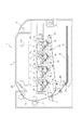
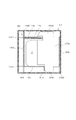
図1は、緩衝材140をカートリッジPに装着した状態で段ボール箱142の中に収容される様子を示した図である。図1に示すように、緩衝材140と段ボール箱142を総称して梱包材143とする。また図5は、カートリッジPが緩衝材140に装着され、段ボール箱142に収容された後の状態を示す図1におけるAーA断面図である。また図6は、図5のBーB断面図である。カートリッジPを包み込むように覆う緩衝材140は、カートリッジPと段ボール箱142の間に位置しており、振動や落下から被梱包物であるカートリッジPを保護する役割を持っている。尚、さらにカートリッジPを埃等から守る為、カートリッジに樹脂製の袋(不図示)に収容した状態で、緩衝材140を装着する構成としてもよい。
≪Composition of packing material≫
FIG. 1 is a diagram showing a state in which the
≪緩衝材の構成≫
図6に示す様に、緩衝材140は、段ボール箱142内において、カートリッジPを支持する構成とされている。緩衝材140は、カートリッジPを囲うように構成され、本実施例では4つの面でカートリッジPの周囲を囲うように巻き付けられ、構成されている。
≪Cushioning material composition≫
As shown in FIG. 6, the
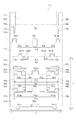
まず初めに、緩衝材140となる段ボールシート141の構成を説明する。図7は、段ボールシート141を示した図である。図7では、破断線を実線、折り曲げ線を破線で図示している。緩衝材140は、段ボールシート141を折り曲げ、組み立てることによって形成されている。段ボールシート141は、第1面141a、第2面(第2の接続面)141b、第3面(対向面)141c、第4面(第1の接続面)141d、第5面(基礎面)141e、第6面141fを有している。第1面141aと第2面141bは、隣接し、折り曲げ線151(151a、151b、151c)で区切られた構成とされている。同様に、第2面141bと第3面141cは、隣接し、折り曲げ線152(152a、152b、152c、152d)で区切られた構成とされている。第3面141cと第4面141dは、隣接し、折り曲げ線153(153a、153b、153c、153d)で区切られた構成とされている。第4面141dと第5面141eは、隣接し、折り曲げ線154(154a、154b、154c、154d)で区切られた構成とされている。第5面141eと第6面141fは、隣接し、折り曲げ線155で区切られた構成とされている。以下の説明では、折り曲げ線151〜155が延びる方向を第一方向(X方向)とし、第1面141a〜第6面141fの配列方向を第二方向(Y方向)として説明を行う。
First, the configuration of the
第1面141aは、第二方向において、一端が第2面141bと折り曲げ線151を介して隣接し、他端が自由端となるように構成されている。第1面141aは、第2面141bとの境界(折り曲げ線151)から第二方向へ延びるスリット170a、170bを備えている。さらに第1面141aは、第二方向における自由端に、自由端側へ突出する凸部141a1、141a2を備えている。この他、第1面141aは、段ボールシート141を緩衝材140とした時に、形状を保持するための係止部195aを備えている。なお、本実施例では、係止部195aを第1面141aに対して折り曲げ可能とされた鉤状部として形成した。
The
第2面141bは、第二方向において、一端が第3面141cと折り曲げ線152を介して隣接し、他端が第1面141aと折り曲げ線151を介して隣接するように構成されている。第2面141bは、第1部分141ba、第2部分141bb、第3部分141bc、とを有する。
The
そして、第2面141bの第1部分141baと第2部分141bbの間には、第1カートリッジ受け面160a(押圧面)が設けられている。第1カートリッジ受け面160aは、第二方向へ延びる切り込み190aによって第2部分141bbと切り離され、スリット170aから第二方向へ延びる折り曲げ線156aで第1部分141baと区切られている。より具体的には、第1カートリッジ受け面160aは、第3面141c側へ向かって突出する凸部141b1と、第1面141a側へ向かって突出する凸部141b4と、を有する。凸部141b1は、周囲が切り抜かれ、第3面141cと分離され、第1カートリッジ受け面160aから折り曲げられることなく突出するように形成されている。同様に凸部141b4は、周囲が切り抜かれ、第1面141aと分離され、第1カートリッジ受け面160aから折り曲げられることなく突出するように形成されている。なお、本実施例では、凸部141b4を形成するための切り抜き部と、スリット170aと、は一体的に形成されている。
A first
また、第2面141bの第2部分141bbと第3部分141bcの間には、第2カートリッジ受け面160b(押圧面)が設けられている。第2カートリッジ受け面160bは、第二方向へ延びる切り込み190bによって第2部分141bbと切り離され、スリット170bから第二方向へ延びる折り曲げ線156bで第3部分141bcと区切られている。より具体的には、第2カートリッジ受け面160bは、第3面141c側へ向かって突出する凸部141b3と、第1面141a側へ向かって突出する凸部141b5と、を有する。凸部141b3は、周囲が切り抜かれ、第3面141cと分離され、第2カートリッジ受け面160bから折り曲げられることなく突出するように形成されている。同様に凸部141b5は、周囲が切り抜かれ、第1面141aと分離され、第2カートリッジ受け面160bから折り曲げられることなく突出するように形成されている。なお、本実施例では、凸部141b5を形成するための切り抜き部と、スリット170bと、は一体的に形成されている。
Further, a second
この他、第2面141bの第2部分141bbは、折り曲げ線152より第二方向の第3面141c側に突出した凸部141b2が設けられている。凸部141b2は、周囲が切り抜かれ、第3面141cと分離され、第2部分141bbから折り曲げられることなく突出するように形成されている。
In addition, the second portion 141bb of the
第3面141cは、第二方向において、一端が第4面141dと折り曲げ線153を介して隣接し、他端が第2面141bと折り曲げ線152を介して隣接するように構成されている。
The
第3面141cは、折り曲げ線153より第二方向の第4面141d側に突出した凸部141c1、141c2が設けられている。凸部141c1、141c2は、周囲が切り抜かれ、第4面141dと分離され、第3面141cから折り曲げられることなく突出するように形成されている。また、第3面141cは、第2面141bとの境界(折り曲げ線152)から第二方向へ延びるスリット170c、170dを備えている。なお、本実施例では、スリット170cは凸部141b1を形成するための切り抜き部と、またスリット170dは凸部141b3を形成するための切り抜き部と、は一体的に形成されている。そして、スリット170c、170dの第二方向の第4面141d側の端部に、補強凸部161a、161bが設けられている。補強凸部161a、161bは、第二方向の第4面141d側においてのみ第一方向へ延びる折り曲げ線157a、157bを介して第3面141cに繋がり、他の周囲の部分については第3面141cと切り離されている。
The
第4面141dは、第二方向において、一端が第3面141cと折り曲げ線153を介して隣接し、他端が第5面141eと折り曲げ線154を介して隣接するように構成されている。第4面141dは、折り曲げ線154より第二方向の第5面141e側に突出した凸部141d1、141d2が設けられている。凸部141d1、141d2は、周囲が切り抜かれ、第5面141eと分離され、第4面141dから折り曲げられることなく突出するように形成されている。同様に第4面141dは、折り曲げ線153より第二方向の第3面141c側に突出した凸部141d3、141d4が設けられている。凸部141d3、141d4は、周囲が切り抜かれ、第3面141cと分離され、第4面141dから折り曲げられることなく突出するように形成されている。
The
第5面141eは、第二方向において、一端が第6面141fと折り曲げ線155を介して隣接し、他端が第4面141dと折り曲げ線154を介して隣接するように構成されている。第5面141eは、第一方向の両端部において、第二方向の第6面141f側に、端部緩衝部180a、180bを備える。
The
端部緩衝部180aは、第5面141eと折り曲げ線158aで区切られ、第一方向における長さが第2面141b、第4面141d、第6面141fの長さに比べ、長くなるように構成されている。なお、端部緩衝部180aと第5面141eを分離する分離部には、第二方向の第4面141d側に延びるスリット170eが繋がった構成とされている。
The
同様に端部緩衝部180bは、第5面141eと折り曲げ線158bで区切られ、第一方向における長さが第2面141b、第4面141d、第6面141fの長さに比べ、長くなるように構成されている。なお、端部緩衝部180bと第5面141eを分離する分離部には、第二方向の第4面141d側に延びるスリット170fが繋がった構成とされている。
Similarly, the
このように、端部緩衝部180a、180bを形成するために、折り曲げ線158a、158bは、折り曲げ線155に比べ、第二方向において第4面141d側に位置する構成としている。
As described above, in order to form the
この他、第5面141eは、段ボールシート141を緩衝材140とした時に、係止部195aと係合し、形状を保持するための非係止部195bを備えている。なお、本実施例では、非係止部195bは、第4面141d及び第5面141eに跨る開口としたが、これに限らず第5面141eのみに形成された開口としてもよい。
In addition, the
第6面141fは、第二方向において、一端が自由端となるように構成され、他端が第5面141eと折り曲げ線155を介して隣接するように構成されている。第一方向の両端部に端部緩衝部180a、180bが形成されているため、第6面141fは、第一方向における長さが第1面141a〜第5面141eに比べ、短くなっている。
The
なお、折り曲げ線151〜155、156a、156b、157a、157b、158a、158bは、段ボールシート141を緩衝材140に組み立てる際に折り曲げやすく加工したものである。折り曲げ線の加工方法は、段ボールシートを直線状に潰して周囲より薄くする加工の他、ミシン目のように一部繋ぎ部分を残して直線状に切り込みを入れる加工等で良く、周囲よりも段ボールシート折り曲げ強度を小さくするものであればよい。
The
≪緩衝材の組立≫
緩衝材140の組立について図7、図8、図9、図10を用いて説明する。なお、被梱包物となるカートリッジPは省略している。
≪Assembly of cushioning material≫
The assembly of the
まず初めに、緩衝材140となる段ボールシート141を用意する。
First, a
次に図8に示すように第1カートリッジ受け面160aを折り曲げ線157a、第2カートリッジ受け面160bを折り曲げ線157bに沿って略直交に折り曲げる。つまり、第1カートリッジ受け面160a、第2カートリッジ受け面160bは、第1面141a〜第6面141fは、と交差する方向(第2方向)に延びた構成とする。折り曲げた第1カートリッジ受け面160aと第2カートリッジ受け面160bの間隔L(図7)が、カートリッジPの長手寸法m(図4)よりも長くなるように配置している。カートリッジP(不図示)は、折り曲げた第1カートリッジ受け面160a、第2カートリッジ受け面160bの間に位置する様に第2面141bの第2部分141bbに置く。
Next, as shown in FIG. 8, the first
そして、図9で示すように、折り曲げ線151〜155の位置で折り曲げ、カートリッジPの周囲に段ボールシート141を巻き付ける。このとき、第6面141f、第2面141bの順に、また第5面141e、第1面141aの順に、カートリッジP側から外方へ重なるようにして、段ボールシート141でカートリッジPを覆う。
Then, as shown in FIG. 9, the
このようにして、第1面141aは、折り曲げ線151に比べ外方へ突出するように延びた凸部141a1、141a2を有するように構成する。同様に第2面141bは、折り曲げ線153に比べ外方へ突出するように延びた凸部141b2を、また折り曲げ線152に比べ外方へ突出するように延びた凸部141b4、141b5を有するように構成する。第3面141cは、折り曲げ線153に比べ外方へ突出するように延びた凸部141c1、141c2を有するように構成する。そして、第4面141dは、折り曲げ線154に比べ外方へ突出するように延びた凸部141d1、141d2を、また折り曲げ線153に比べ外方へ突出するように延びた凸部141d3、141d4を有するように構成する。
In this way, the
また図9及び図10で示すように、段ボールシート141の巻き付け工程と同時に、スリット170cに第1カートリッジ受け面160aの凸部141b1を挿入し、貫通させ、補強凸部161aを凸部141b1で押す。このようにして、図11に示すように折り曲げ線157aで第2面141bの第1部分141baから第1カートリッジ受け面160aを折り、第1カートリッジ受け面160aを凸部141b1で第3面141cから突出した状態とする。つまり、補強凸部161aは、カートリッジPの周囲を囲う段ボールシート141の外周面において、段ボールシート141(第3面141c)から交差する方向に突出するように構成されている。本実施例では、補強凸部161aは、第3面141c、つまり折り曲げ線153と153の配列方向における、折り曲げ線153と153の略中間に配置した。さらに、補強凸部161aは凸部141b1と接触し、第3面141cと交差する方向に突出しており、第3面141cと平行な断面がT字形状とした。
Further, as shown in FIGS. 9 and 10, at the same time as the winding step of the
同様に、第2面141bと第3面141cを折り曲げ線152で折り曲げ、緩衝材140を組み立てる際には、スリット170dに凸部141b3を挿入し、第2カートリッジ受け面160bを凸部141b3で押す。このようにして、図11に示すように折り曲げ線157bで第2面141bの第1部分141baから第2カートリッジ受け面160bが折れ曲がり、第2カートリッジ受け面160bを凸部141b3で突出した状態とする。つまり、凸部141b3は、補強凸部161bの略中間に配置され、水平面における断面がT字形状とされる。
Similarly, when the
また、段ボールシート141を組み立てる際には、端部緩衝部180aを第5面141eとの成す角が鋭角となるように折り曲げ線158aで折り曲げた後、第1カートリッジ受け面160aの凸部141b4を第5面141eのスリット170eに挿入する。このように、第5面141eと凸部141b4が干渉しない構成としている。同様に、端部緩衝部180bを第5面141eとのなす角Xが鋭角となるように折り曲げ線158bで折り曲げた後、第2カートリッジ受け面160bの凸部141b5を第5面141eのスリット170fに挿入する。このように、第5面141eと凸部141bfが干渉しない構成としている。
Further, when assembling the
そして、第1面141aと第2面141bを折り曲げ線151で折り曲げ、緩衝材140を組み立てる際には、第1カートリッジ受け面160aの凸部141b4を第1面141aに設けたスリット170aに挿入する。同様に、第2カートリッジ受け面160bの凸部141b5を第1面141aに設けたスリット170bに挿入する。なお、本実施例では第1カートリッジ受け面160aの凸部141b4、及び第2カートリッジ受け面160bの凸部141b5は、鉤形状とし、それぞれ挿入されたスリット170a、170bから外れにくい構成としている。
Then, when the
最後に、第1面141aに設けた係止部195aを第5面141eに設けられた非係止部195bに嵌めこみ、被梱包体であるカートリッジPを内包した緩衝材140を形成する。
Finally, the locking
≪段ボール緩衝材の端部構成≫
次に、緩衝材140の第一方向における端部の緩衝構成について、詳細に説明を行う。緩衝材140は、第一方向における一端に第1カートリッジ受け面160a、端部緩衝面180a及び折り曲げ線158a、第一方向における他端に第2カートリッジ受け面160b、端部緩衝面180b、及び折り曲げ線158bを同様に有している。そこで、第一方向の一端に位置する第1カートリッジ受け面160a及び端部緩衝面180a等からなる緩衝構成を例に挙げ、図12を用いて説明を行う。図12は、緩衝材140を第一方向の一端側から見た時の状態を示した概略図である。
≪End structure of corrugated cardboard cushioning material≫
Next, the cushioning configuration of the end portion of the
第1カートリッジ受け面160aは、段ボールシート141において、第2面141bの第2部分141bbと折り曲げ線157aで繋がる構成とされている。そして、緩衝部材140とされた時にあっては、第1カートリッジ受け面160aは、第2面141bの第2部分141bbと、折り曲げ線157aで交差するように屈曲させられている。第1カートリッジ受け面160aは、凸部141b1が第3面141cのスリット170cに、また凸部141b4が第1面141aのスリット170a及び第5面141eのスリット170eに、挿入されている。これにより、第1カートリッジ受け面160aは、段ボールシート141の巻き付け方向と交差する方向に延びる面となるようにされている。
The first
そして本実施例では、段ボールシート141の巻き付け方向と交差する方向(第一方向)において、第1カートリッジ受け面160aの被梱包物が配置される側と反対側に、端部緩衝面180aが設けられている。つまり緩衝材140は、第一方向において外方へ向かって、被梱包物となるカートリッジP、第1カートリッジ受け面160a、端部緩衝面180a、の順で有する構成とされている。
Then, in the present embodiment, the
端部緩衝面180aは、その一端が第5面141eに折り曲げ線158aを介して繋がり、他端Jは自由端とされた構成とされ、他端Jは第5面141eの対向面である第3面141cに当接している。また、折り曲げ線154と折り曲げ線158aの間に位置する第5面141eの長さt2は、折り曲げ線152と折り曲げ線153の間に位置する第3面141cの長さt3を二等分した長さより長くなるように構成する(t2>t3/2)。そして、折り曲げ線158aに繋がる一端から他端Jまで延びる端部緩衝面180aの長さTを第5面141eと第3面141cとの間の距離t1より長い構成とするとともに、端部緩衝面180aと第5面141eのなす角Xを鋭角(X<90°)とする。
One end of the
この構成により、折り曲げ線158aで折り曲げられた端部緩衝面180aには、緩衝材140を構成する部材(本実施例では、段ボール)が折り曲げられる前の状態へ戻ろうとする反力Fが作用する。なお反力Fは、図12に示すように、折り曲げ線158aを回動中心として生じる力であって、端部緩衝面180aと第5面141eのなす角Xが大きくなるような力である。
With this configuration, a reaction force F that tries to return to the state before the member (corrugated cardboard in this embodiment) constituting the
また、端部緩衝面180aの長さTが第5面141eと第3面141cとの間の距離t1よりも長い。このため、反力Fによって他端Jが端部緩衝面180aの面141cに接触し、端部緩衝面180aは動きが規制される。つまり、図12に示すように、端部緩衝面180aは、長手方向の端部から中央部を見た時に、第1カートリッジ受け面160aを二分する位置で動きが規制されるように設定される。
Further, the length T of the
このように構成された緩衝材140をカートリッジPに装着し、段ボール箱142に収容したものを用意し、図13に示すように、カートリッジPの下方に第1カートリッジ受け面160aが位置する状態で鉛直方向Gへ落下させた状態を示す。図13は、図12におけるC−C断面を第1方向の外方から内方を見た図である。カートリッジPは、落下方向Gに落下された時、第1カートリッジ受け面160aに支えられる。そして、第1カートリッジ受け面160aに加わった落下の衝撃が第1面141a〜第5面141e(図12参照)に加え、端部緩衝面180aに加わり、変形するようにしている。すなわち、撓みや折れが生じ得る過度な荷重が第1カートリッジ受け面160aに加わった際に、端部緩衝面180aが変形しつつ、第1カートリッジ受け面160aを支えることで、第1カートリッジ受け面160aに撓みや折れが生じることを抑制する。この結果、カートリッジPの荷重が第1カートリッジ受け面160aに加わり、第1カートリッジ受け面160aが撓んだり、折れたりして、段ボール箱142の内壁面に突き当たり、被梱包物であるカートリッジPに衝撃が加わることを抑制することができる。
The
なお、上記説明では、第一方向における一端の構成について説明したが、第一方向における他端の構成についても同様とされている。つまり、他端においても、第1カートリッジ受け面160aを第2カートリッジ受け面160b、端部緩衝面180aを端部緩衝面180b、そして折り曲げ線158aを折り曲げ線158b、と置き換えることにより一端と同様に構成することができる。
In the above description, the configuration of one end in the first direction has been described, but the same applies to the configuration of the other end in the first direction. That is, at the other end, the first
[変形例]
なお、上記実施例では、図12に示すように端部緩衝面180aは、他端Jが第3面141cに当接する構成とした。しかし、これに限らず、本発明の実施例の変形例として図14に示すように、端部緩衝面180aの位置を第3面141cの一部を切り欠くことで形成した切り欠き部141caで規制する構成としてもよい。なお、切り欠き部141caを設けた点の他は、上記実施例と同様の構成としているため、同様の構成については同じ符号を付し、説明を省略する。
[Modification example]
In the above embodiment, as shown in FIG. 12, the
図14は、変形例に係る緩衝材140を第一方向の一端側から見た時の状態を示した概略図である。変形例においても、端部緩衝面180aの長さTを第5面141eと第3面141cとの間の距離t1より長い構成とするとともに、端部緩衝面180aと第5面141eのなす角Xが鋭角(X<90°)となるようにしている。この構成により、端部緩衝面180aには反力Fが作用し、端部緩衝面180aが切り欠き部141caに接触して端部緩衝面180aの動きが規制される。
FIG. 14 is a schematic view showing a state when the
このように構成された変形例に係る緩衝材140は、上記実施例同様、撓みや折れが生じ得る過度な荷重が第1カートリッジ受け面160aに加わった場合であっても、端部緩衝面180aが変形しつつ、第1カートリッジ受け面160aを支える。この結果、カートリッジPの荷重が第1カートリッジ受け面160aに加わり、第1カートリッジ受け面160aが撓んだり、折れたりして、段ボール箱142の内壁面に突き当たり、被梱包物であるカートリッジPに衝撃が加わることを抑制することができる。
The
なお、第3面141cは、端部緩衝面180aと当接し、端部緩衝面180aの位置を規制する切り欠き部141caを有する構成であればよい。このため、切り欠き部141caは図14に示した形状に限らず、第3面141cの形状に自由度を持たせることができ、組み立て性や緩衝能力の向上を図ることも可能となる。
The
P カートリッジ
140 緩衝材
141 段ボールシート
141a〜141f 面
142 段ボール箱
143 梱包材
151〜155、156a、156b、157a、157b、158a、158b 折り曲げ線
160a、160b カートリッジ受け面
161a、161b 補強凸部
141a1、141a2、141b1〜141b5、141c1、141c2、141d1〜141d4 凸部
170a〜170d スリット
180a、180b 端部緩衝部
190a、190b 切り込み
Claims (11)
前記緩衝材は、前記被梱包物の周囲に巻き付けられたシートからなり、
基礎面と、
前記基礎面と対向する対向面と、
を少なくとも備え、
前記基礎面は、前記シートが巻き付けられる方向と交差する方向の端部において、端部緩衝部の一端と第1折り曲げ線を介して繋がり、
前記端部緩衝部は、前記交差する方向において前記被梱包物の外方に位置し、前記端部緩衝部の他端は、前記対向面と接触する
ことを特徴とする緩衝材。 A cushioning material that is attached to the packaged item and housed in a box.
The cushioning material consists of a sheet wrapped around the packaged object.
The basics and
The facing surface facing the foundation surface and
At least
The foundation surface is connected to one end of the end cushioning portion via a first bending line at an end portion in a direction intersecting the direction in which the sheet is wound.
A cushioning material characterized in that the end cushioning portion is located outside the packaged object in the intersecting direction, and the other end of the end cushioning portion is in contact with the facing surface .
ことを特徴とする請求項1に記載の緩衝材。 The cushioning material according to claim 1, wherein the angle formed between the foundation surface and the end cushioning portion is an acute angle.
ことを特徴とする請求項2に記載の緩衝材。 The cushioning material according to claim 2, wherein the length from one end to the other end of the end cushioning portion is longer than the length between the foundation surface and the facing surface .
ことを特徴とする請求項1ないし4のいずれか1項に記載の緩衝材。 Claims 1 to 1, wherein the sheet is arranged between the packaged object and the end cushioning portion in the intersecting direction, and has a receiving surface for receiving the packaged object. The cushioning material according to any one of 4.
前記基礎面と第3折り曲げ線を介して、また前記対向面と第4折り曲げ線を介して繋がる第1の接続面と、
前記対向面と第5折り曲げ線を介して繋がる第2の接続面と、
を少なくとも備え、
前記基礎面、前記第1の接続面、前記対向面、前記第2の接続面は、順次、繋がり、前記被梱包物の周囲を覆う
ことを特徴とする請求項1ないし6のいずれか1項に記載の緩衝材。 The cushioning material further comprises a first connecting surface that is connected to the foundation surface via a third bending line and to the facing surface via a fourth bending line.
A second connecting surface connected to the facing surface via a fifth bending line,
At least
One of claims 1 to 6 , wherein the foundation surface , the first connecting surface , the facing surface , and the second connecting surface are sequentially connected to cover the periphery of the packaged object. Cushioning material described in.
ことを特徴とする請求項7に記載の緩衝材。 The length between the first folding line and the third folding line is longer than the length obtained by bisecting the length between the fourth folding line and the fifth folding line. The cushioning material according to claim 7.
ことを特徴とする請求項1ないし8のいずれか1項に記載の緩衝材。 The cushioning material according to any one of claims 1 to 8, wherein the sheet is corrugated cardboard.
ことを特徴とする請求項1ないし9のいずれか1項に記載の緩衝材。 The object to be packed, the cushioning material according to any one of claims 1 to 9, characterized in <br/> comprises a cartridge for use in an image forming apparatus.
前記箱と、
請求項1ないし10のいずれか1項に記載の緩衝材と、
を有することを特徴とする梱包体。 With the packaged object
With the box
The cushioning material according to any one of claims 1 to 10 and
A packaging body characterized by having.
Priority Applications (1)
| Application Number | Priority Date | Filing Date | Title |
|---|---|---|---|
| JP2016069287A JP6786239B2 (en) | 2016-03-30 | 2016-03-30 | Cushioning material and packing body |
Applications Claiming Priority (1)
| Application Number | Priority Date | Filing Date | Title |
|---|---|---|---|
| JP2016069287A JP6786239B2 (en) | 2016-03-30 | 2016-03-30 | Cushioning material and packing body |
Publications (3)
| Publication Number | Publication Date |
|---|---|
| JP2017178385A JP2017178385A (en) | 2017-10-05 |
| JP2017178385A5 JP2017178385A5 (en) | 2019-04-18 |
| JP6786239B2 true JP6786239B2 (en) | 2020-11-18 |
Family
ID=60003588
Family Applications (1)
| Application Number | Title | Priority Date | Filing Date |
|---|---|---|---|
| JP2016069287A Active JP6786239B2 (en) | 2016-03-30 | 2016-03-30 | Cushioning material and packing body |
Country Status (1)
| Country | Link |
|---|---|
| JP (1) | JP6786239B2 (en) |
Families Citing this family (27)
| Publication number | Priority date | Publication date | Assignee | Title |
|---|---|---|---|---|
| JP2020036801A (en) * | 2018-09-05 | 2020-03-12 | 株式会社三洋物産 | Game machine |
| JP2020036798A (en) * | 2018-09-05 | 2020-03-12 | 株式会社三洋物産 | Game machine |
| JP2020036800A (en) * | 2018-09-05 | 2020-03-12 | 株式会社三洋物産 | Game machine |
| JP2020036799A (en) * | 2018-09-05 | 2020-03-12 | 株式会社三洋物産 | Game machine |
| JP2020036802A (en) * | 2018-09-05 | 2020-03-12 | 株式会社三洋物産 | Game machine |
| JP2020146314A (en) * | 2019-03-14 | 2020-09-17 | 株式会社三洋物産 | Game machine |
| JP2020146306A (en) * | 2019-03-14 | 2020-09-17 | 株式会社三洋物産 | Game machine |
| JP2020146313A (en) * | 2019-03-14 | 2020-09-17 | 株式会社三洋物産 | Game machine |
| JP2020146304A (en) * | 2019-03-14 | 2020-09-17 | 株式会社三洋物産 | Game machine |
| JP2020146310A (en) * | 2019-03-14 | 2020-09-17 | 株式会社三洋物産 | Game machine |
| JP2020146311A (en) * | 2019-03-14 | 2020-09-17 | 株式会社三洋物産 | Game machine |
| JP2020146302A (en) * | 2019-03-14 | 2020-09-17 | 株式会社三洋物産 | Game machine |
| JP2020146312A (en) * | 2019-03-14 | 2020-09-17 | 株式会社三洋物産 | Game machine |
| JP2020146309A (en) * | 2019-03-14 | 2020-09-17 | 株式会社三洋物産 | Game machine |
| JP2020146303A (en) * | 2019-03-14 | 2020-09-17 | 株式会社三洋物産 | Game machine |
| JP2020146316A (en) * | 2019-03-14 | 2020-09-17 | 株式会社三洋物産 | Game machine |
| JP2020146307A (en) * | 2019-03-14 | 2020-09-17 | 株式会社三洋物産 | Game machine |
| JP2020146297A (en) * | 2019-03-14 | 2020-09-17 | 株式会社三洋物産 | Game machine |
| JP2020146308A (en) * | 2019-03-14 | 2020-09-17 | 株式会社三洋物産 | Game machine |
| JP2020146305A (en) * | 2019-03-14 | 2020-09-17 | 株式会社三洋物産 | Game machine |
| JP2020146318A (en) * | 2019-03-14 | 2020-09-17 | 株式会社三洋物産 | Game machine |
| JP2020146317A (en) * | 2019-03-14 | 2020-09-17 | 株式会社三洋物産 | Game machine |
| JP2020146298A (en) * | 2019-03-14 | 2020-09-17 | 株式会社三洋物産 | Game machine |
| JP2020146300A (en) * | 2019-03-14 | 2020-09-17 | 株式会社三洋物産 | Game machine |
| JP2020146299A (en) * | 2019-03-14 | 2020-09-17 | 株式会社三洋物産 | Game machine |
| JP2020146301A (en) * | 2019-03-14 | 2020-09-17 | 株式会社三洋物産 | Game machine |
| JP2020146315A (en) * | 2019-03-14 | 2020-09-17 | 株式会社三洋物産 | Game machine |
Family Cites Families (8)
| Publication number | Priority date | Publication date | Assignee | Title |
|---|---|---|---|---|
| JP3006478U (en) * | 1994-07-08 | 1995-01-24 | 中津川包装工業株式会社 | Cardboard cushion case |
| JPH1035734A (en) * | 1996-07-26 | 1998-02-10 | Tec Corp | Packing apparatus |
| JP4338805B2 (en) * | 1999-01-08 | 2009-10-07 | レンゴー株式会社 | Cardboard cushion |
| JP2001348069A (en) * | 2000-06-07 | 2001-12-18 | Canon Chemicals Inc | Corrugated cardboard cushioning member |
| US7021024B2 (en) * | 2001-08-02 | 2006-04-04 | Fidelity Container Corporation | Cartridge insert which fits into a box |
| TWI263612B (en) * | 2004-05-25 | 2006-10-11 | Accton Technology Corp | Structure of folded and glued packing box |
| JP4920345B2 (en) * | 2006-08-25 | 2012-04-18 | 京セラミタ株式会社 | Shock absorber for packing box |
| JP5729632B2 (en) * | 2010-12-09 | 2015-06-03 | 株式会社リコー | Packing material |
-
2016
- 2016-03-30 JP JP2016069287A patent/JP6786239B2/en active Active
Also Published As
| Publication number | Publication date |
|---|---|
| JP2017178385A (en) | 2017-10-05 |
Similar Documents
| Publication | Publication Date | Title |
|---|---|---|
| JP6786239B2 (en) | Cushioning material and packing body | |
| KR101657037B1 (en) | Packaged cartridge | |
| US10427867B2 (en) | Packing member and cartridge packed in the packing member | |
| JP6732496B2 (en) | Cushioning material, package, and manufacturing method of cushioning material | |
| JP2011191427A (en) | Image forming cartridge and image forming device | |
| JP6622451B2 (en) | Packing material | |
| JP6779733B2 (en) | Cushioning material | |
| JP2004264757A (en) | Protective cover of development cartridge | |
| JP2008260556A (en) | Packing material | |
| JP6297187B2 (en) | Packaging materials and cartridges | |
| JP2020170083A (en) | Packing member and packing body | |
| JP6323003B2 (en) | Package | |
| WO2019077967A1 (en) | Packing container and package | |
| WO2019177126A1 (en) | Packing member and package | |
| JP2019163084A (en) | Packing member and package unit | |
| WO2019176890A1 (en) | Packing member and packing unit | |
| JP2020170085A (en) | Packing member and packing body | |
| TW202142462A (en) | Packaging member and package | |
| JP2014081404A (en) | Packaging member and cartridge packaged by packaging member | |
| JP2019179071A (en) | Developer storage container, developing device, and process cartridge |
Legal Events
| Date | Code | Title | Description |
|---|---|---|---|
| A521 | Written amendment |
Free format text: JAPANESE INTERMEDIATE CODE: A523 Effective date: 20190308 |
|
| A621 | Written request for application examination |
Free format text: JAPANESE INTERMEDIATE CODE: A621 Effective date: 20190308 |
|
| A977 | Report on retrieval |
Free format text: JAPANESE INTERMEDIATE CODE: A971007 Effective date: 20191224 |
|
| A131 | Notification of reasons for refusal |
Free format text: JAPANESE INTERMEDIATE CODE: A131 Effective date: 20200107 |
|
| A521 | Written amendment |
Free format text: JAPANESE INTERMEDIATE CODE: A523 Effective date: 20200305 |
|
| TRDD | Decision of grant or rejection written | ||
| A01 | Written decision to grant a patent or to grant a registration (utility model) |
Free format text: JAPANESE INTERMEDIATE CODE: A01 Effective date: 20200929 |
|
| A61 | First payment of annual fees (during grant procedure) |
Free format text: JAPANESE INTERMEDIATE CODE: A61 Effective date: 20201028 |
|
| R151 | Written notification of patent or utility model registration |
Ref document number: 6786239 Country of ref document: JP Free format text: JAPANESE INTERMEDIATE CODE: R151 |