JP6786235B2 - Image display device - Google Patents
Image display device Download PDFInfo
- Publication number
- JP6786235B2 JP6786235B2 JP2016062144A JP2016062144A JP6786235B2 JP 6786235 B2 JP6786235 B2 JP 6786235B2 JP 2016062144 A JP2016062144 A JP 2016062144A JP 2016062144 A JP2016062144 A JP 2016062144A JP 6786235 B2 JP6786235 B2 JP 6786235B2
- Authority
- JP
- Japan
- Prior art keywords
- hdr
- region
- image
- light emitting
- divided
- Prior art date
- Legal status (The legal status is an assumption and is not a legal conclusion. Google has not performed a legal analysis and makes no representation as to the accuracy of the status listed.)
- Active
Links
Images


Description
本発明は、画像表示装置に関する。 The present invention relates to an image display device.
ダイナミックレンジが広い画像データが扱われる機会が増している。ダイナミックレンジが広い画像データは、「HDR(High Dynamic Range)画像データ」と呼ばれる。例えば、撮影によってHDR画像データを生成可能な撮影装置がある。HDR画像データは、画像編集などの非放送系の作業においてよく使用される。HDR画像データの規格としては、例えば、SMPTE(Society of Motion Picture and Television Engineers;全米映画テレビ協会)によって提唱された「SMPT ST 2084」がある。 There are increasing opportunities for image data with a wide dynamic range to be handled. Image data having a wide dynamic range is called "HDR (High Dynamic Range) image data". For example, there is a photographing device capable of generating HDR image data by photographing. HDR image data is often used in non-broadcasting work such as image editing. As a standard of HDR image data, for example, there is "SMPT ST 2084" proposed by SMPTE (Society of Motion Picture and Television Engineers; National Film and Television Association).
広いダイナミックレンジでの表示(HDR表示)を画像表示装置が行う際に、SMPTE ST 2084で規定されたPQ(Perceptual Quantizer)カーブが考慮されることが求められている。PQカーブは、人間の目が弁別できる輝度差を基準に作成されたカーブである。PQカーブは、0.005〜10000cd/m2の広い輝度レンジで規定されている。 When the image display device performs display in a wide dynamic range (HDR display), it is required that the PQ (Perfectual Quantizer) curve defined by SMPTE ST 2084 be taken into consideration. The PQ curve is a curve created based on the brightness difference that can be discriminated by the human eye. The PQ curve is defined by a wide luminance range of 0.005-10000 cd / m 2 .
また、液晶表示装置などの画像表示装置では、ローカルデミング処理が行われることがある(特許文献1)。ローカルデミング処理では、画面の領域を構成する複数の分割領域にそれぞれ対応する複数の発光領域を有する発光部(バックライト部)が使用される。具体的には、各発光領域の発光輝度が個別に制御され、各発光領域の発光輝度に基づいて画像データの伸長処理が行われる。それにより、表示画像(画面に表示された画像)のコントラストが向上される。また、HDR表示を実現するために、バックライト部の高輝度化が進められている。バックライト部(発光領域)の発光輝度の上限値を高めることにより、表示画像のコントラストをさらに高めることができる。 Further, in an image display device such as a liquid crystal display device, local deming processing may be performed (Patent Document 1). In the local demming process, a light emitting unit (backlight unit) having a plurality of light emitting areas corresponding to each of the plurality of divided areas constituting the screen area is used. Specifically, the emission brightness of each light emitting region is individually controlled, and the image data is expanded based on the emission brightness of each light emitting region. As a result, the contrast of the displayed image (the image displayed on the screen) is improved. Further, in order to realize the HDR display, the brightness of the backlight portion is being increased. By increasing the upper limit of the emission brightness of the backlight portion (emission region), the contrast of the displayed image can be further increased.
HDR表示が行われる場合、多くの発光領域において、発光輝度が非常に高い輝度に制御されることがある。そのため、画像表示装置の消費電力が増大することがある。しかしながら、映画などの画像コンテンツの撮影現場においては、画像表示装置がバッテリーで駆動され、画像表示装置で撮影画像のHDR表示が行われることがある。そのような場合、上述した消費電力の増大により、長時間のHDR表示を画像表示装置が行えず、長時間の撮影に画像表示装置が使用できないことがある。画像表示装置がACアダプタで駆動されれば、画像表示装置は、長時間のHDR表示を行うことができる。しかしながら、画面の多くの領域において非常に高い輝度での表示が行われた場合に、眩しさによりユーザの目の疲労が増大することがある。 When HDR display is performed, the emission brightness may be controlled to a very high brightness in many light emitting regions. Therefore, the power consumption of the image display device may increase. However, at the shooting site of image content such as a movie, the image display device may be driven by a battery, and the image display device may perform HDR display of the shot image. In such a case, due to the increase in power consumption described above, the image display device may not be able to perform HDR display for a long time, and the image display device may not be usable for long-time shooting. If the image display device is driven by the AC adapter, the image display device can perform HDR display for a long time. However, glare can increase user eye fatigue when very high brightness is displayed in many areas of the screen.
本発明は、HDR表示の際の画像表示装置の消費電力と、HDR表示を確認する際のユーザの疲労感とを低減することができる技術を提供することを目的とする。 An object of the present invention is to provide a technique capable of reducing the power consumption of an image display device at the time of HDR display and the feeling of fatigue of the user when confirming the HDR display.
本発明の第1の態様は、
画面を構成する複数の分割領域にそれぞれ対応する複数の発光領域を有する発光手段と、
前記発光手段からの光を変調することにより、入力画像に基づく表示画像を前記画面に表示する表示手段と、
前記複数の分割領域にそれぞれ対応する複数の輝度特徴量を、前記入力画像から取得する特徴量取得手段と、
第1のダイナミックレンジよりも広い第2のダイナミックレンジを示すレンジ情報を取得する第1の情報取得手段と、
前記画面に表示された前記表示画像の一部の画像領域であるHDR画像領域を示す領域情報を取得する第2の情報取得手段と、
前記領域情報に基づいて、前記複数の分割領域から、前記HDR画像領域に対応する分割領域であるHDR分割領域と、前記HDR画像領域に対応しない分割領域である非HDR分割領域とを検出する検出手段と、
前記複数の分割領域のそれぞれの輝度特徴量、前記レンジ情報、及び、前記HDR分割領域と前記非HDR分割領域の検出結果に基づいて、前記非HDR分割領域において前記第1のダイナミックレンジでの表示が行われ、かつ、前記HDR分割領域において前記第2のダイナミックレンジでの表示が行われるように、前記複数の発光領域のそれぞれの発光輝度の個別制御と、前記入力画像の階調変換とを行う制御手段と、
を有し、
前記制御手段は、前記表示画像とともに、前記HDR画像領域を示す第1のグラフィック画像、又は、前記HDR分割領域ではなくかつ前記発光手段から発せられて前記表示手段に照射される光の輝度が閾値以上である前記画面の領域を示す第2のグラフィック画像が表示されるように、前記入力画像と前記第1又は第2のグラフィック画像とを合成する合成手段を有する
ことを特徴とする画像表示装置である。
本発明の第2の態様は、
画面を構成する複数の分割領域にそれぞれ対応する複数の発光領域を有する発光手段と、
前記発光手段からの光を変調することにより、入力画像に基づく表示画像を前記画面に表示する表示手段と、
前記複数の分割領域にそれぞれ対応する複数の輝度特徴量を、前記入力画像から取得する特徴量取得手段と、
第1のダイナミックレンジよりも広い第2のダイナミックレンジを示すレンジ情報を取得する第1の情報取得手段と、
前記画面に表示された前記表示画像の一部の画像領域であるHDR画像領域を示す領域情報を取得する第2の情報取得手段と、
前記領域情報に基づいて、前記複数の分割領域から、前記HDR画像領域に対応する分割領域であるHDR分割領域と、前記HDR画像領域に対応しない分割領域である非HDR分割領域とを検出する検出手段と、
前記複数の分割領域のそれぞれの輝度特徴量、前記レンジ情報、及び、前記HDR分割領域と前記非HDR分割領域の検出結果に基づいて、前記非HDR分割領域において前記第1のダイナミックレンジでの表示が行われ、かつ、前記HDR分割領域において前記第2のダイナミックレンジでの表示が行われるように、前記複数の発光領域のそれぞれの発光輝度の個別制御と、前記入力画像の階調変換とを行う制御手段と、
を有し、
前記制御手段は、
前記複数の分割領域のそれぞれの輝度特徴量、前記レンジ情報、及び、前記HDR分割領域と前記非HDR分割領域の検出結果に基づいて、前記複数の発光領域のそれぞれの発光輝度を決定する決定手段と、
前記レンジ情報、前記HDR分割領域と前記非HDR分割領域の検出結果、及び、前記複数の発光領域のそれぞれの発光輝度に基づいて、前記入力画像の階調変換を行う階調変換手段と、
を有し、
前記決定手段は、前記複数の発光領域のうち、前記非HDR分割領域に対応する発光領域の発光輝度を、前記第1のダイナミックレンジに対応して設定された第1の輝度レンジを用いて決定し、前記複数の発光領域のうち、前記HDR分割領域に対応する発光領域の発光輝度を、前記第2のダイナミックレンジに対応して設定された第2の輝度レンジを用いて決定し、
前記第1の輝度レンジと前記第2の輝度レンジの比は、前記第1のダイナミックレンジと前記第2のダイナミックレンジの比と一致する
ことを特徴とする画像表示装置である。
The first aspect of the present invention is
A light emitting means having a plurality of light emitting regions corresponding to a plurality of divided regions constituting the screen,
A display means for displaying a display image based on an input image on the screen by modulating the light from the light emitting means.
A feature amount acquisition means for acquiring a plurality of luminance features corresponding to each of the plurality of divided regions from the input image, and
A first information acquisition means for acquiring range information indicating a second dynamic range wider than the first dynamic range, and
A second information acquisition means for acquiring area information indicating an HDR image area, which is a part of the display image displayed on the screen, and
Detection to detect an HDR divided region, which is a divided region corresponding to the HDR image region, and a non-HDR divided region, which is a divided region not corresponding to the HDR image region, from the plurality of divided regions based on the region information. Means and
Display in the first dynamic range in the non-HDR division region based on the respective luminance features of the plurality of division regions, the range information, and the detection results of the HDR division region and the non-HDR division region. The individual control of the emission luminance of each of the plurality of emission regions and the gradation conversion of the input image are performed so that the display is performed in the second dynamic range in the HDR division region. Control measures to be performed and
Have,
The control means, together with the display image, has a threshold value of the brightness of the first graphic image showing the HDR image region, or the light emitted from the light emitting means and not the HDR division region and applied to the display means. An image display device comprising a compositing means for synthesizing the input image and the first or second graphic image so that the second graphic image indicating the area of the screen as described above is displayed. Is.
A second aspect of the present invention is
A light emitting means having a plurality of light emitting regions corresponding to a plurality of divided regions constituting the screen,
A display means for displaying a display image based on an input image on the screen by modulating the light from the light emitting means.
A feature amount acquisition means for acquiring a plurality of luminance features corresponding to each of the plurality of divided regions from the input image, and
A first information acquisition means for acquiring range information indicating a second dynamic range wider than the first dynamic range, and
A second information acquisition means for acquiring area information indicating an HDR image area, which is a part of the display image displayed on the screen, and
Detection to detect an HDR divided region, which is a divided region corresponding to the HDR image region, and a non-HDR divided region, which is a divided region not corresponding to the HDR image region, from the plurality of divided regions based on the region information. Means and
Display in the first dynamic range in the non-HDR division region based on the respective luminance features of the plurality of division regions, the range information, and the detection results of the HDR division region and the non-HDR division region. The individual control of the emission luminance of each of the plurality of emission regions and the gradation conversion of the input image are performed so that the display is performed in the second dynamic range in the HDR division region. Control measures to be performed and
Have,
The control means
A determination means for determining the emission brightness of each of the plurality of light emitting regions based on the respective luminance features of the plurality of divided regions, the range information, and the detection results of the HDR divided region and the non-HDR divided region. When,
A gradation conversion means that performs gradation conversion of the input image based on the range information, the detection results of the HDR divided region and the non-HDR divided region, and the emission brightness of each of the plurality of light emitting regions.
Have,
The determining means determines the emission brightness of the light emitting region corresponding to the non-HDR divided region among the plurality of light emitting regions by using the first luminance range set corresponding to the first dynamic range. Then, among the plurality of light emitting regions, the light emitting brightness of the light emitting region corresponding to the HDR divided region is determined using the second luminance range set corresponding to the second dynamic range .
The image display device is characterized in that the ratio of the first luminance range to the second luminance range matches the ratio of the first dynamic range and the second dynamic range .
本発明の第3の態様は、
画面を構成する複数の分割領域にそれぞれ対応する複数の発光領域を有する発光手段と、
前記発光手段からの光を変調することにより、入力画像に基づく表示画像を前記画面に表示する表示手段と、
を有する画像表示装置の制御方法であって、
前記複数の分割領域にそれぞれ対応する複数の輝度特徴量を、前記入力画像から取得する特徴量取得ステップと、
第1のダイナミックレンジよりも広い第2のダイナミックレンジを示すレンジ情報を取得する第1の情報取得ステップと、
前記画面に表示された前記表示画像の一部の画像領域であるHDR画像領域を示す領域情報を取得する第2の情報取得ステップと、
前記領域情報に基づいて、前記複数の分割領域から、前記HDR画像領域に対応する分割領域であるHDR分割領域と、前記HDR画像領域に対応しない分割領域である非HD
R分割領域とを検出する検出ステップと、
前記複数の分割領域のそれぞれの輝度特徴量、前記レンジ情報、及び、前記HDR分割領域と前記非HDR分割領域の検出結果に基づいて、前記非HDR分割領域において前記第1のダイナミックレンジでの表示が行われ、かつ、前記HDR分割領域において前記第2のダイナミックレンジでの表示が行われるように、前記複数の発光領域のそれぞれの発光輝度の個別制御と、前記入力画像の階調変換とを行う制御ステップと、
を有し、
前記制御ステップは、前記表示画像とともに、前記HDR画像領域を示す第1のグラフィック画像、又は、前記HDR分割領域ではなくかつ前記発光手段から発せられて前記表示手段に照射される光の輝度が閾値以上である前記画面の領域を示す第2のグラフィック画像が表示されるように、前記入力画像と前記第1又は第2のグラフィック画像とを合成する合成ステップを含む
ことを特徴とする画像表示装置の制御方法である。
本発明の第4の態様は、
画面を構成する複数の分割領域にそれぞれ対応する複数の発光領域を有する発光手段と、
前記発光手段からの光を変調することにより、入力画像に基づく表示画像を前記画面に表示する表示手段と、
を有する画像表示装置の制御方法であって、
前記複数の分割領域にそれぞれ対応する複数の輝度特徴量を、前記入力画像から取得する特徴量取得ステップと、
第1のダイナミックレンジよりも広い第2のダイナミックレンジを示すレンジ情報を取得する第1の情報取得ステップと、
前記画面に表示された前記表示画像の一部の画像領域であるHDR画像領域を示す領域情報を取得する第2の情報取得ステップと、
前記領域情報に基づいて、前記複数の分割領域から、前記HDR画像領域に対応する分割領域であるHDR分割領域と、前記HDR画像領域に対応しない分割領域である非HDR分割領域とを検出する検出ステップと、
前記複数の分割領域のそれぞれの輝度特徴量、前記レンジ情報、及び、前記HDR分割領域と前記非HDR分割領域の検出結果に基づいて、前記非HDR分割領域において前記第1のダイナミックレンジでの表示が行われ、かつ、前記HDR分割領域において前記第2のダイナミックレンジでの表示が行われるように、前記複数の発光領域のそれぞれの発光輝度の個別制御と、前記入力画像の階調変換とを行う制御ステップと、
を有し、
前記制御ステップは、
前記複数の分割領域のそれぞれの輝度特徴量、前記レンジ情報、及び、前記HDR分割領域と前記非HDR分割領域の検出結果に基づいて、前記複数の発光領域のそれぞれの発光輝度を決定する決定ステップと、
前記レンジ情報、前記HDR分割領域と前記非HDR分割領域の検出結果、及び、前記複数の発光領域のそれぞれの発光輝度に基づいて、前記入力画像の階調変換を行う階調変換ステップと、
を含み、
前記決定ステップでは、前記複数の発光領域のうち、前記非HDR分割領域に対応する発光領域の発光輝度を、前記第1のダイナミックレンジに対応して設定された第1の輝度レンジを用いて決定し、前記複数の発光領域のうち、前記HDR分割領域に対応する発光領域の発光輝度を、前記第2のダイナミックレンジに対応して設定された第2の輝度レンジを用いて決定し、
前記第1の輝度レンジと前記第2の輝度レンジの比は、前記第1のダイナミックレンジと前記第2のダイナミックレンジの比と一致する
ことを特徴とする画像表示装置の制御方法である。
A third aspect of the present invention is
A light emitting means having a plurality of light emitting regions corresponding to a plurality of divided regions constituting the screen,
A display means for displaying a display image based on an input image on the screen by modulating the light from the light emitting means.
It is a control method of an image display device having
A feature amount acquisition step of acquiring a plurality of luminance features corresponding to each of the plurality of divided regions from the input image, and
The first information acquisition step of acquiring range information indicating a second dynamic range wider than the first dynamic range, and
A second information acquisition step of acquiring area information indicating an HDR image area, which is a part of the display image displayed on the screen, and
Based on the area information, from the plurality of divided areas, an HDR divided area which is a divided area corresponding to the HDR image area and a non-HD which is a divided area not corresponding to the HDR image area.
A detection step for detecting the R division area and
Display in the first dynamic range in the non-HDR division region based on the respective luminance features of the plurality of division regions, the range information, and the detection results of the HDR division region and the non-HDR division region. The individual control of the emission luminance of each of the plurality of emission regions and the gradation conversion of the input image are performed so that the display is performed in the second dynamic range in the HDR division region. Control steps to perform and
Have,
In the control step, the brightness of the first graphic image showing the HDR image region or the light emitted from the light emitting means and not the HDR divided region and radiated to the display means is a threshold value together with the display image. An image display device comprising a compositing step of synthesizing the input image and the first or second graphic image so that the second graphic image indicating the area of the screen as described above is displayed. It is a control method of.
A fourth aspect of the present invention is
A light emitting means having a plurality of light emitting regions corresponding to a plurality of divided regions constituting the screen,
A display means for displaying a display image based on an input image on the screen by modulating the light from the light emitting means.
It is a control method of an image display device having
A feature amount acquisition step of acquiring a plurality of luminance features corresponding to each of the plurality of divided regions from the input image, and
The first information acquisition step of acquiring range information indicating a second dynamic range wider than the first dynamic range, and
A second information acquisition step of acquiring area information indicating an HDR image area, which is a part of the display image displayed on the screen, and
Detection to detect an HDR divided region, which is a divided region corresponding to the HDR image region, and a non-HDR divided region, which is a divided region not corresponding to the HDR image region, from the plurality of divided regions based on the region information. Steps and
Display in the first dynamic range in the non-HDR division region based on the respective luminance features of the plurality of division regions, the range information, and the detection results of the HDR division region and the non-HDR division region. The individual control of the emission luminance of each of the plurality of emission regions and the gradation conversion of the input image are performed so that the display is performed in the second dynamic range in the HDR division region. Control steps to perform and
Have,
The control step
A determination step of determining the emission brightness of each of the plurality of light emitting regions based on the respective luminance features of the plurality of divided regions, the range information, and the detection results of the HDR divided region and the non-HDR divided region. When,
A gradation conversion step for performing gradation conversion of the input image based on the range information, the detection results of the HDR divided region and the non-HDR divided region, and the emission brightness of each of the plurality of light emitting regions.
Including
In the determination step, the emission brightness of the emission region corresponding to the non-HDR division region among the plurality of emission regions is determined using the first luminance range set corresponding to the first dynamic range. Then, among the plurality of light emitting regions, the light emitting brightness of the light emitting region corresponding to the HDR divided region is determined using the second luminance range set corresponding to the second dynamic range .
A control method for an image display device, characterized in that the ratio of the first luminance range to the second luminance range matches the ratio of the first dynamic range to the second dynamic range .
本発明の第5の態様は、上述した画像表示装置の制御方法の各ステップをコンピュータに実行させるためのプログラムである。
A fifth aspect of the present invention is a program for causing a computer to execute each step of the above-described image display device control method.
本発明によれば、HDR表示の際の画像表示装置の消費電力と、HDR表示を確認する際のユーザの疲労感とを低減することができる。 According to the present invention, it is possible to reduce the power consumption of the image display device at the time of HDR display and the feeling of fatigue of the user when confirming the HDR display.
<実施例1>
以下、本発明の実施例1に係る画像表示装置について説明する。なお、以下では、本実施例に係る画像表示装置が透過型の液晶表示装置である場合の例を説明するが、本実施例に係る画像表示装置は透過型の液晶表示装置に限らない。本実施例に係る画像表示装置は、発光部と、発光部からの光を画像データに基づいて変調することにより画面に画像を表示する表示部と、を有する画像表示装置であればよい。例えば、本実施例に係る画像表示装置は、反射型の液晶表示装置であってもよい。また、本実施例に係る画像表示装置は、液晶素子の代わりにMEMS(Micro Electro Mechanical System)シャッターを用いたMEMSシャッター方式表示装置であってもよい。
<Example 1>
Hereinafter, the image display device according to the first embodiment of the present invention will be described. In the following, an example in which the image display device according to this embodiment is a transmissive liquid crystal display device will be described, but the image display device according to this embodiment is not limited to the transmissive liquid crystal display device. The image display device according to the present embodiment may be an image display device having a light emitting unit and a display unit that displays an image on the screen by modulating the light from the light emitting unit based on the image data. For example, the image display device according to this embodiment may be a reflective liquid crystal display device. Further, the image display device according to the present embodiment may be a MEMS shutter type display device using a MEMS (Micro Electro Mechanical System) shutter instead of the liquid crystal element.
本実施例に係る画像表示装置の発光部は、画面の領域を構成する複数の分割領域にそれぞれ対応する複数の発光領域を有する。複数の発光領域の発光輝度は、個別に制御することができる。各発光領域の発光輝度の個別制御と、入力画像データ(画像表示装置に入力された画像データ)の補正とを行うことにより、本実施例に係る画像表示装置は、複数の分割領域のそれぞれにおいて、様々なダイナミックレンジでの表示を行うことができる。 The light emitting unit of the image display device according to the present embodiment has a plurality of light emitting regions corresponding to the plurality of divided regions constituting the screen region. The emission brightness of the plurality of emission regions can be controlled individually. By individually controlling the emission brightness of each light emitting region and correcting the input image data (image data input to the image display device), the image display device according to the present embodiment can be used in each of the plurality of divided regions. , Can be displayed in various dynamic ranges.
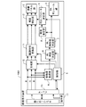
図1A,1Bは、本実施例に係る画像表示装置の機能構成の一例を示すブロック図である。図1Aでは、本実施例に係る画像表示装置1は、情報処理装置13を含む画像表示システムにおいて使用される。画像表示装置1の外部装置である情報処理装置13としては、ワークステーション、パーソナルコンピュータ、スマートフォン、等を使用することができる。
1A and 1B are block diagrams showing an example of the functional configuration of the image display device according to the present embodiment. In FIG. 1A, the
図1Aでは、情報処理装置13に搭載されたビューアアプリケーション(ビューア)と、画像表示装置1とが連携することで、レンジ情報と領域情報が、情報処理装置13から画像表示装置1に通知(入力)される。レンジ情報は、予め定められた基準のダイナミックレンジ(SDR;第1のダイナミックレンジ)よりも広いダイナミックレンジ(HDR;第2のダイナミックレンジ)を示す。領域情報は、HDRでの表示を行う画像領域(HDR領域;選択領域)を示す。HDRは、例えば、HDR領域に対してユーザが所望するダイナミックレンジである。HDR領域は、例えば、HDRでの表示(HDR表示)をユーザが所望する画像領域である。
In FIG. 1A, the range information and the area information are notified (input) from the
そして、図1Aでは、画像表示装置1が、HDR領域に対応する分割領域を、HDR分割領域(対応分割領域)として決定する。その後、画像表示装置1が、HDR分割領域においてHDR表示が行われ、かつ、非HDR分割領域(非対応分割領域)においてSDR表示が行われるように、各発光領域の発光輝度の個別制御と、入力画像データの補正とを行う。非HDR分割領域は、HDR分割領域以外(対応分割領域以外)の分割領域であり、SDR表示は、SDRでの表示である。これにより、HDR表示が行われる領域がHDR領域に制限されるため、HDR表示の際の画像表示装置の消費電力と、HDR表示を確認する際のユーザの疲労感とを低減することができる。
Then, in FIG. 1A, the
さらに、図1Aでは、画像表示装置1が、HDR表示が行われた画面の領域をユーザに通知する。これにより、HDR表示が行われた領域と、それ以外の領域とをユーザが容易に把握可能となる。その結果、HDR表示が行われた領域における表示画像(画面に表示された画像)の画質と、それ以外の領域における表示画像の画質との確認作業の利便性を向上することができる。
Further, in FIG. 1A, the
図1Bでは、本実施例に係る画像表示装置1001が、図1Aの情報処理装置13の機能をさらに有する。そのため、図1Bでは、画像表示装置1001は、画像表示装置1001に対するユーザ操作に応じて、レンジ情報と領域情報を取得する。例えば、画像表示装置1001は、HDRを選択するユーザ操作に応じてレンジ情報を取得したり、HDR領域を選択するユーザ操作に応じて領域情報を取得したりする。画像表示装置1001は、画像表示装置1001の動作モードを設定するユーザ操作に応じて、レンジ情報と領域情報の少なくとも一方を取得してもよい。画像表示装置1001に対するユーザ操作を受け付ける入力装置としては、キーボード、マウス、画像編集専用のジョグダイアルを有する特殊な入力装置、画像表示装置1001の画面に設けられたタッチパネル、等を使用することができる。
In FIG. 1B, the
なお、図1Aにおいて、レンジ情報と領域情報の少なくとも一方は、情報処理装置13(外部装置)から画像表示装置1に入力されなくてもよい。例えば、画像表示装置1が、
画像表示装置1に対するユーザ操作に応じて、レンジ情報と領域情報の少なくとも一方を取得してもよい。
In FIG. 1A, at least one of the range information and the area information does not have to be input from the information processing device 13 (external device) to the
At least one of the range information and the area information may be acquired according to the user operation on the
以下では、図1Aの画像表示システムについて詳しく説明する。図1Bの画像表示装置1001で行われる処理は、図1Aの画像表示システムで行われる処理と同様であるため、図1Bの画像表示装置1001についての詳しい説明は省略する。
The image display system of FIG. 1A will be described in detail below. Since the processing performed by the
まず、画像表示装置1について説明する。画像表示装置1は、液晶パネル部2、BLモジュール部3、特徴量取得部4、制御部5、BL輝度決定部6、BL制御値決定部7、輝度推定部8、補正パラメータ決定部9、合成部10、階調特性変換部11、輝度補正部12、及び、画像取得部18を有する。
First, the
液晶パネル部2は、BLモジュール部3からの光を画像データに基づいて透過(変調)することにより、画面に画像を表示する。液晶パネル部2は、複数の液晶素子を有する液晶パネル、各液晶素子を駆動する液晶ドライバ、及び、液晶ドライバの処理を制御するコントロール基板を有する。コントロール基板は、液晶パネル部2に入力された画像データに基づいて、液晶ドライバの処理を制御する。それにより、各液晶素子の透過率が、液晶パネル部2に入力された画像データに応じた値に制御される。BLモジュール部3からの光は、液晶パネル部2に入力された画像データに応じた透過率で各液晶素子を通過する。それにより、液晶パネル部2に入力された画像データに基づく画像が画面に表示される。
The liquid
BLモジュール部3は、複数の発光領域を有する発光部である。BLモジュール部3は、液晶パネル部2(液晶パネル)の背面に光を照射する。各発光領域は、BL制御値決定部7で決定されたBL制御値に応じた発光輝度で発光する。各発光領域には、1つ以上の光源が設けられている。BLモジュール部3は、複数の光源、各光源を駆動する駆動回路、及び、各光源からの光を拡散する光学ユニットを有する。本実施例では、複数の分割領域がマトリクス状に配列しており、複数の発光領域もマトリクス状に配列している。具体的には、画面の領域が、水平方向10個×垂直方向6個の分割領域で構成されており、BLモジュール部3は、水平方向10個×垂直方向6個の発光領域を有する。光源としては、例えば、LED(発光ダイオード)、有機EL素子、冷陰極管、等を使用することができる。
The
本実施例では、画面の領域が、水平方向1920個×垂直方向1080個の画素で構成されている。そして、本実施例では、画面の領域が、サイズが互いに等しい複数の分割領域で構成されている。上述したように、本実施例では、画面の領域が水平方向10個×垂直方向6個の分割領域で構成されている。そのため、各分割領域は水平方向192個×垂直方向180個の画素で構成される。 In this embodiment, the screen area is composed of 1920 pixels in the horizontal direction and 1080 pixels in the vertical direction. Then, in this embodiment, the screen area is composed of a plurality of divided areas having the same size. As described above, in this embodiment, the screen area is composed of 10 horizontal direction × 6 vertical direction divided areas. Therefore, each divided region is composed of 192 pixels in the horizontal direction and 180 pixels in the vertical direction.
なお、画面のサイズ、分割領域の数、分割領域の配置、分割領域のサイズ、発光領域の数、発光領域の配置、及び、発光領域のサイズは、特に限定されない。画面の領域を構成する画素の数は、水平方向1920個×垂直方向1080個より多くても少なくてもよい。分割領域の数は、60個より多くても少なくてもよい。複数の分割領域が千鳥格子状に配列していてもよい。複数の分割領域のサイズが互いに異なっていてもよい。発光領域についても同様である。 The size of the screen, the number of divided areas, the arrangement of the divided areas, the size of the divided areas, the number of light emitting areas, the arrangement of the light emitting areas, and the size of the light emitting areas are not particularly limited. The number of pixels constituting the area of the screen may be more or less than 1920 in the horizontal direction × 1080 in the vertical direction. The number of divided regions may be more or less than 60. A plurality of divided regions may be arranged in a houndstooth pattern. The sizes of the plurality of divided areas may be different from each other. The same applies to the light emitting region.
画像取得部18は、情報処理装置13から入力画像データ(表示対象の画像データである対象画像データ)を取得する。画像取得部18は、取得した対象画像データを、特徴量取得部4と合成部10に出力する。本実施例では、12ビットのRGB値(12ビットのR値、12ビットのG値、及び、12ビットのB値)を画素値として有する画像データが、対象画像データとして取得される。なお、対象画像データのデータフォーマット(画素
値のビット数、画素値の種類、等)は特に限定されない。例えば、12ビットのYDxDz値(12ビットのY値、12ビットのDx値、及び、12ビットのDz値)を画素値として有する画像データが、対象画像データとして取得されてもよい。10ビットのYCbCr値(10ビットのY値、10ビットのCb値、及び、10ビットのCr値)を画素値として有する画像データが、対象画像データとして取得されてもよい。
The
特徴量取得部4は、複数の分割領域のそれぞれについて、その分割領域に対応する画像データの輝度特徴量を、対象画像データから取得する。特徴量取得部4は、各分割領域の輝度特徴量を、BL輝度決定部6に出力する。輝度特徴量は、輝度に関する特徴量である。本実施例では、階調値(R値、G値、及び、B値)の最大値である最大階調値が、輝度特徴量として取得される。例えば、R値の最大値が50であり、G値の最大値が1000であり、B値の最大値が100である場合には、1000が輝度特徴量として取得される。
The feature
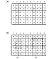
図2(A)は、対象画像データの一例を示し、図2(B)は、図2(A)の対象画像データから得られた輝度特徴量(最大階調値)を示す。図2(B)において、水平方向に並んだ1〜10の数値は、分割領域の水平位置(水平方向における位置)を示し、垂直方向に並んだ1〜6の数値は、分割領域の垂直位置(垂直方向における位置)を示す。上述したように、対象画像データの階調値は、12ビットの値(0〜4095)である。図2(A)において、画面上部のオブジェクト101は、高輝度で表現されたオブジェクトである。図2(B)に示すように、オブジェクト101の少なくとも一部が表示される分割領域の輝度特徴量(最大階調値)は、3100または3200である。
FIG. 2A shows an example of the target image data, and FIG. 2B shows a luminance feature amount (maximum gradation value) obtained from the target image data of FIG. 2A. In FIG. 2B, the
なお、輝度特徴量は、最大階調値に限らない。例えば、階調値の他の代表値(最小値、平均値、最頻値、中間値、等)が輝度特徴量として取得されてもよい。階調値のヒストグラムが輝度特徴量として取得されてもよい。閾値よりも大きい階調値を有する画素(明部画素)の数が、輝度特徴量として取得されてもよい。閾値よりも小さい階調値を有する画素(暗部画素)の数が、輝度特徴量として取得されてもよい。階調値として輝度値(Y値)を用いて、輝度特徴量が取得されてもよい。 The luminance feature amount is not limited to the maximum gradation value. For example, other representative values of gradation values (minimum value, average value, mode value, intermediate value, etc.) may be acquired as the luminance feature amount. A histogram of the gradation value may be acquired as a luminance feature amount. The number of pixels (bright portion pixels) having a gradation value larger than the threshold value may be acquired as the luminance feature amount. The number of pixels (dark area pixels) having a gradation value smaller than the threshold value may be acquired as the luminance feature amount. The luminance feature amount may be acquired by using the luminance value (Y value) as the gradation value.
制御部5は、レンジ情報を情報処理装置13から取得する(第1の情報取得)。また、制御部5は、領域情報を情報処理装置13から取得する(第2の情報取得)。そして、制御部5は、領域情報に基づいて、複数の分割領域からHDR分割領域を検出する。本実施例では、HDR領域の少なくとも一部が表示される分割領域が、HDR分割領域として検出される。制御部5は、HDR分割領域の検出結果を、BL輝度決定部6、補正パラメータ決定部9、合成部10、及び、階調特性変換部11に出力する。また、制御部5は、レンジ情報を、BL輝度決定部6、補正パラメータ決定部9、及び、階調特性変換部11に出力する。
The
図3(A)は、HDR領域の一例を示す。図3(A)において、破線130で囲まれた領域が、HDR領域である。図3(A)では、オブジェクト101を含む領域が、HDR領域として指定されている。画像表示装置1は、1つの分割領域において、SDR表示とHDR表示の両方を行うことはできない。しかしながら、HDR領域は、分割領域を考慮せずに指定されることがある。そのため、HDR領域の輪郭が複数の分割領域の間の境界に対応するとは限らない。そこで、制御部5は、HDR領域の少なくとも一部を含む分割領域を、HDR分割領域として検出する。
FIG. 3A shows an example of the HDR region. In FIG. 3A, the region surrounded by the
図3(A)の破線130で囲まれた領域がHDR領域である場合におけるHDR分割領域の検出結果を、図3(B),3(C)に示す。図3(B)において、破線131で囲まれた領域は、複数のHDR分割領域からなる領域を示す。図3(C)において、「1」が
記載された分割領域はHDR分割領域であり、「0」が記載された分割領域は非HDR分割領域である。制御部5は、例えば、HDR分割領域の検出結果として、複数の分割領域のそれぞれに「0」または「1」を関連付けた情報を出力する。
The detection results of the HDR division region when the region surrounded by the
なお、HDR分割領域の検出方法は上記方法に限らない。例えば、HDR領域の少なくとも一部を含む分割領域と、それに隣接する分割領域とが、HDR分割領域として検出されてもよい。HDR領域の少なくとも一部のみを含む分割領域が、HDR分割領域として検出されてもよい。HDR領域の少なくとも一部のみを含む分割領域と、それに隣接する分割領域とが、HDR分割領域として検出されてもよい。 The method for detecting the HDR division region is not limited to the above method. For example, a divided region including at least a part of the HDR region and a divided region adjacent thereto may be detected as the HDR divided region. A divided region containing at least a part of the HDR region may be detected as an HDR divided region. A divided region including at least a part of the HDR region and a divided region adjacent thereto may be detected as the HDR divided region.
BL輝度決定部6とBL制御値決定部7により、各発光領域の発光輝度の個別制御が行われる。そして、輝度推定部8、補正パラメータ決定部9、階調特性変換部11、及び、輝度補正部12により、対象画像データの補正が行われる。本実施例では、非HDR分割領域においてSDR表示が行われ、かつ、HDR分割領域においてHDR表示が行われるように、各発光領域の発光輝度の個別制御と、対象画像データの補正とが行われる。この処理には、各分割領域の輝度特徴量、レンジ情報、及び、HDR分割領域の検出結果が使用される。各分割領域の輝度特徴量、レンジ情報、及び、HDR分割領域の検出結果を用いた方法であれば、どのような方法で、各発光領域の発光輝度の個別制御と、対象画像データの補正とが行われてもよい。本実施例では、各分割領域の輝度特徴量、レンジ情報、及び、HDR分割領域の検出結果に基づいて、各発光領域の発光輝度の個別制御が行われる。そして、レンジ情報、HDR分割領域の検出結果、及び、各発光領域の発光輝度に基づいて、対象画像データの補正が行われる。
The BL
BL輝度決定部6は、各分割領域の輝度特徴量、レンジ情報、及び、HDR分割領域の検出結果に基づいて、各発光領域の発光輝度(目標輝度)を決定する。BL輝度決定部6は、各発光領域の発光輝度を示す情報を、BL制御値決定部7に出力する。本実施例では、BL輝度決定部6は、複数の発光領域のそれぞれについて、その発光領域に対応する分割領域の輝度特徴量に基づいて、当該発光領域の発光輝度を決定する。発光輝度の決定において、非HDR分割領域に対応する発光領域の発光輝度のレンジとして、SDRに対応する第1の輝度レンジが使用され、かつ、HDR割領域に対応する発光領域の発光輝度のレンジとして、HDRに対応する第2の輝度レンジが使用される。例えば、BL輝度決定部6は、レンジ情報と、HDR分割領域の検出結果とに基づいて、輝度特徴量と発光輝度の対応関係を示す情報(BL変換情報;ルックアップテーブル、関数、等)を、複数の発光領域のそれぞれについて設定または生成する。そして、BL輝度決定部6は、複数の発光領域のそれぞれについて、BL変換情報と輝度特徴量から発光輝度を決定する。具体的には、BL輝度決定部6は、BL変換情報が示す対応関係において発光領域(分割領域)の輝度特徴量に対応する発光輝度を、当該発光領域の発光輝度として決定する。
The BL
本実施例では、第1の輝度レンジと第2の輝度レンジの比が、HDRとSDRの比と一致する例を説明する。本実施例では、第1の輝度レンジの最小輝度が第2の輝度レンジの最小輝度と一致し、かつ、SDRの最小輝度がHDRの最小輝度と一致する場合の例を説明する。具体的には、第1の輝度レンジの最小輝度、第2の輝度レンジの最小輝度、SDRの最小輝度、及び、HDRの最小輝度が、画像データの階調値の下限値に対応する輝度と一致する場合の例を説明する。しかし、第1の輝度レンジと第2の輝度レンジの比は、HDRとSDRの比と異なっていてもよい。第1の輝度レンジの最小輝度は、第2の輝度レンジの最小輝度と異なっていてもよい。SDRの最小輝度は、HDRの最小輝度と異なっていてもよい。第1の輝度レンジの最小輝度、第2の輝度レンジの最小輝度、SDRの最小輝度、及び、HDRの最小輝度の少なくともいずれかは、画像データの階調値の下限値に対応する輝度と異なっていてもよい。 In this embodiment, an example in which the ratio of the first luminance range and the second luminance range matches the ratio of HDR and SDR will be described. In this embodiment, an example will be described in which the minimum luminance in the first luminance range matches the minimum luminance in the second luminance range, and the minimum luminance in the SDR matches the minimum luminance in the HDR. Specifically, the minimum luminance in the first luminance range, the minimum luminance in the second luminance range, the minimum luminance in SDR, and the minimum luminance in HDR correspond to the lower limit of the gradation value of the image data. An example of a match will be described. However, the ratio of the first luminance range to the second luminance range may be different from the ratio of HDR to SDR. The minimum luminance in the first luminance range may be different from the minimum luminance in the second luminance range. The minimum brightness of SDR may be different from the minimum brightness of HDR. At least one of the minimum luminance in the first luminance range, the minimum luminance in the second luminance range, the minimum luminance in SDR, and the minimum luminance in HDR is different from the luminance corresponding to the lower limit of the gradation value of the image data. You may be.
BL変換情報が示す対応関係の一例を図4(A),4(B)に示す。図4(A),4(B)の横軸は、輝度特徴量である最大階調値を示し、図4(A),4(B)の縦軸は、発光輝度を示す。発光輝度0%は、発光領域が点灯しない状態に対応し、発光輝度100%は、発光領域が上限の発光輝度で点灯する状態に対応する。非HDR分割領域に対応する発光領域の発光輝度は、図4(A)に示す対応関係に従って決定される。HDR分割領域に対応する発光領域の発光輝度は、図4(B)に示す対応関係に従って決定される。 An example of the correspondence relationship shown by the BL conversion information is shown in FIGS. 4 (A) and 4 (B). The horizontal axis of FIGS. 4 (A) and 4 (B) indicates the maximum gradation value which is the luminance feature amount, and the vertical axis of FIGS. 4 (A) and 4 (B) indicates the emission luminance. The emission brightness of 0% corresponds to a state in which the light emission region is not lit, and the emission brightness of 100% corresponds to a state in which the light emission region is lit at the upper limit emission brightness. The emission brightness of the emission region corresponding to the non-HDR division region is determined according to the correspondence relationship shown in FIG. 4 (A). The emission brightness of the emission region corresponding to the HDR division region is determined according to the correspondence relationship shown in FIG. 4 (B).
本実施例では、SDRが0〜200cd/m2のレンジであり、かつ、HDRが0〜2000cd/m2のレンジであるとする。そして、詳細は後述するが、SDRの最大輝度に対応する階調値は1803であり、HDRの最大輝度に対応する階調値は3141である。図4(A)において、発光輝度のレンジ(第1の輝度レンジ)は0〜10%のレンジである。図4(B)において、発光輝度のレンジ(第2の輝度レンジ)は0〜100%のレンジである。このように、本実施例では、第1の輝度レンジと第2の輝度レンジの比(10/100)は、SDRとHDRの比(200/2000)と一致する。
In this embodiment, SDR is
図4(A),4(B)では、SRDの最大輝度に対応する階調値以下の最大階調値に対して、最大階調値の増加に伴い第1の輝度レンジの最小輝度から第1の輝度レンジの最大輝度まで増加する発光輝度が対応付けられている。具体的には、1803以下の最大階調値に対して、最大階調値の増加に伴い0%から10%まで増加する発光輝度が対応付けられている。そして、図4(A)では、SDRの最大輝度に対応する階調値よりも大きい最大階調値に対して、第1の輝度レンジの最大輝度と同じ発光輝度が対応付けられている。具体的には、1803よりも大きい最大階調値に対して、10%の発光輝度が対応付けられている。 In FIGS. 4 (A) and 4 (B), with respect to the maximum gradation value equal to or less than the gradation value corresponding to the maximum brightness of the SRD, as the maximum gradation value increases, the minimum brightness in the first luminance range is changed to the first. Emission brightness that increases up to the maximum brightness in the brightness range of 1 is associated. Specifically, the emission brightness that increases from 0% to 10% as the maximum gradation value increases is associated with the maximum gradation value of 1803 or less. Then, in FIG. 4A, the same emission brightness as the maximum brightness of the first brightness range is associated with the maximum gradation value larger than the gradation value corresponding to the maximum brightness of SDR. Specifically, 10% emission brightness is associated with a maximum gradation value larger than 1803.
図4(B)では、SDRの最大輝度に対応する階調値以上であり、かつ、HDRの最大輝度に対応する階調値以下である最大階調値に対して、最大階調値の増加に伴い増加する発光輝度が対応付けられている。具体的には、最大階調値の増加に伴い第1の輝度レンジの最大輝度から第2の輝度レンジの最大輝度まで増加する発光輝度が対応付けられている。より具体的には、1083以上であり、かつ、3141以下である最大階調値に対して、最大階調値の増加に伴い10%から100%まで増加する発光輝度が対応付けられている。そして、図4(B)では、HDRの最大輝度に対応する階調値よりも大きい最大階調値に対して、第2の輝度レンジの最大輝度と同じ発光輝度が対応付けられている。具体的には、4095よりも大きい最大階調値に対して、100%の発光輝度が対応付けられている。 In FIG. 4B, the maximum gradation value is increased with respect to the maximum gradation value which is equal to or more than the gradation value corresponding to the maximum brightness of SDR and is equal to or less than the gradation value corresponding to the maximum brightness of HDR. The emission brightness that increases with this is associated. Specifically, as the maximum gradation value increases, the emission luminance that increases from the maximum luminance in the first luminance range to the maximum luminance in the second luminance range is associated. More specifically, the emission brightness that increases from 10% to 100% as the maximum gradation value increases is associated with the maximum gradation value that is 1083 or more and 3141 or less. Then, in FIG. 4B, the same emission brightness as the maximum brightness of the second brightness range is associated with the maximum gradation value larger than the gradation value corresponding to the maximum brightness of HDR. Specifically, 100% emission brightness is associated with the maximum gradation value larger than 4095.
なお、図4(A),4(B)には、最大階調値と発光輝度の対応関係として線形特性を繋ぎ合わせた対応関係が示されているが、最大階調値と発光輝度の対応関係は図4(A),4(B)に示す対応関係に限らない。例えば、最大階調値の少なくとも一部のレンジにおいて、最大階調値の増加に伴い発光輝度が指数関数的に増加してもよい。ダイナミックレンジの輝度と階調値の対応関係(表示輝度(画面の輝度)と階調値の対応関係)を考慮して、最大階調値と発光輝度の対応関係が決定されてもよい。 Although FIGS. 4 (A) and 4 (B) show a correspondence relationship in which linear characteristics are connected as a correspondence relationship between the maximum gradation value and the emission brightness, the correspondence between the maximum gradation value and the emission brightness is shown. The relationship is not limited to the correspondence shown in FIGS. 4 (A) and 4 (B). For example, in at least a part of the range of the maximum gradation value, the emission brightness may increase exponentially as the maximum gradation value increases. The correspondence between the maximum gradation value and the emission brightness may be determined in consideration of the correspondence between the brightness of the dynamic range and the gradation value (the correspondence between the display brightness (screen brightness) and the gradation value).
各分割領域の最大階調値として、図2(B)に示す最大階調値が得られた場合の例を説明する。HDR領域が存在しない場合には、図5(A)に示すように、全ての分割領域が非HDR分割領域として設定される。図5(A)において、「0」が記載された分割領域は非HDR分割領域である。そのため、全ての発光領域の発光輝度が、図4(A)の対応関係に従って決定される。その結果、各発光領域の発光輝度として、図5(B)に示す発光輝度が得られる。 An example will be described when the maximum gradation value shown in FIG. 2B is obtained as the maximum gradation value of each divided region. When the HDR region does not exist, as shown in FIG. 5A, all the divided regions are set as non-HDR divided regions. In FIG. 5A, the division area marked with “0” is a non-HDR division area. Therefore, the emission brightness of all the emission regions is determined according to the correspondence relationship shown in FIG. 4 (A). As a result, the emission brightness shown in FIG. 5B is obtained as the emission brightness of each light emission region.
HDR分割領域の検出結果として、図3(C)に示す結果が得られた場合には、図3(
C)の太線で囲まれた分割領域に対応する発光領域が、図4(B)の対応関係に従って決定される。具体的には、(水平位置,垂直位置)=(7,1)〜(7,3)、(8,1)〜(8,3)、及び、(9,1)〜(9,3)の9個の発光領域の発光輝度が、図4(B)の対応関係に従って決定される。そして、残りの発光領域の発光輝度が、図4(A)の対応関係に従って決定される。その結果、各発光領域の発光輝度として、図5(C)に示す発光輝度が得られる。
When the result shown in FIG. 3C is obtained as the detection result of the HDR division region, FIG. 3 (
The light emitting region corresponding to the divided region surrounded by the thick line in C) is determined according to the correspondence relationship in FIG. 4 (B). Specifically, (horizontal position, vertical position) = (7,1) to (7,3), (8,1) to (8,3), and (9,1) to (9,3). The emission brightness of the nine light emitting regions of is determined according to the correspondence relationship of FIG. 4 (B). Then, the emission brightness of the remaining light emission region is determined according to the correspondence relationship of FIG. 4 (A). As a result, the emission brightness shown in FIG. 5C is obtained as the emission brightness of each light emission region.
BL制御値決定部7は、BL輝度決定部6で決定された各発光領域の発光輝度(目標輝度)を、BL制御値に変換する。BL制御値決定部7は、各発光領域のBL制御値を、BLモジュール部3に出力する。それにより、各発光領域が、BL輝度決定部6で決定された発光輝度で発光する。また、BL制御値決定部7は、各発光領域のBL制御値を輝度推定部8にも出力する。発光領域の光源の発光輝度がパルス幅変調方式で制御される場合には、パルス幅を示す値がBL制御値として使用される。発光領域の光源の発光輝度がパルス振幅変調方式で制御される場合には、パルス振幅を示す値がBL制御値として使用される。パルス幅とパルス振幅の両方を変調する方式で発光輝度が制御される場合には、パルス幅とパルス振幅を示す値がBL制御値として使用される。
The BL control
合成部10は、補正後の対象画像データに基づく画像に加え、第1のグラフィック画像がさらに表示されるように、HDR分割領域の検出結果に基づいて、第1のグラフィック画像を表す第1のグラフィック画像データの合成を行う(第1の合成)。それにより、対象画像データに第1のグラフィック画像データを合成した合成画像データが生成される。第1のグラフィック画像は、HDRでの表示が行われた画面の領域(HDR表示領域)を示すグラフィック画像である。例えば、第1のグラフィック画像は、図3(B)の破線131のような画像(矩形の枠画像)である。第1のグラフィック画像が表示されることにより、HDR表示領域がユーザに通知される。換言すれば、ユーザは、表示された第1のグラフィック画像を確認することにより、HDR表示領域を把握することができる。合成部10は、合成画像データを階調特性変換部11に出力する。なお、合成部10は省略されてもよい。
The synthesizing
階調特性変換部11は、レンジ情報と、HDR分割領域の検出結果とに基づいて、画像データの階調特性を変換する変換処理を行う。変換処理により、画像データの階調値のレンジに対応する表示輝度のレンジがSDRと一致するように、非HDR分割領域に対応する画像データの階調特性が変換される。また、変換処理により、画像データの階調値のレンジに対応する表示輝度のレンジがHDRと一致するように、HDR分割領域に対応する画像データの階調特性が変換される。本実施例では、合成画像データに変換処理が施される。それにより、変換画像データが生成される。階調特性変換部11は、変換画像データを輝度補正部12に出力する。
The gradation
図6(A)〜6(C)を用いて、変換処理の具体例を説明する。図6(A)〜6(C)の縦軸は輝度を示し、図6(A)〜6(C)の横軸は階調値を示す。図6(A)は、階調値と輝度(表示輝度)の対応関係を示す。なお、階調値と輝度の対応関係は図6(A)の対応関係に限らない。 Specific examples of the conversion process will be described with reference to FIGS. 6 (A) to 6 (C). The vertical axis of FIGS. 6 (A) to 6 (C) indicates the brightness, and the horizontal axis of FIGS. 6 (A) to 6 (C) indicates the gradation value. FIG. 6A shows the correspondence between the gradation value and the brightness (display brightness). The correspondence between the gradation value and the brightness is not limited to the correspondence in FIG. 6A.
本実施例では、SDRの最大輝度は、200cd/m2である。図6(B)に示すように、200cd/m2に対応する階調値は1803である。変換処理では、非HDR分割領域に対応する画像データの階調値が1803よりも大きい場合に、当該階調値が1803に変換される。即ち、非HDR分割領域に対応する画像データの階調値の上限値が、1803に制限される。その後、非HDR分割領域に対応する画像データの階調値のレンジが、0〜1803のレンジから、元のレンジ(0〜4095)のレンジに拡大される。 In this embodiment, the maximum brightness of the SDR is 200 cd / m 2 . As shown in FIG. 6B, the gradation value corresponding to 200 cd / m 2 is 1803. In the conversion process, when the gradation value of the image data corresponding to the non-HDR division region is larger than 1803, the gradation value is converted to 1803. That is, the upper limit of the gradation value of the image data corresponding to the non-HDR divided region is limited to 1803. After that, the range of gradation values of the image data corresponding to the non-HDR divided region is expanded from the range of 0 to 1803 to the range of the original range (0 to 4095).
また、本実施例では、HDRの最大輝度は、2000cd/m2である。図6(C)に示すように、2000cd/m2に対応する階調値は3141である。変換処理では、HDR分割領域に対応する画像データの階調値が3141よりも大きい場合に、当該階調値が3141に変換される。即ち、HDR分割領域に対応する画像データの階調値の上限値が、3141に制限される。その後、HDR分割領域に対応する画像データの階調値のレンジが、0〜3141のレンジから、元のレンジ(0〜4095)のレンジに拡大される。 Further, in this embodiment, the maximum brightness of HDR is 2000 cd / m 2 . As shown in FIG. 6C, the gradation value corresponding to 2000 cd / m 2 is 3141. In the conversion process, when the gradation value of the image data corresponding to the HDR division region is larger than 3141, the gradation value is converted to 3141. That is, the upper limit of the gradation value of the image data corresponding to the HDR division region is limited to 3141. After that, the range of the gradation value of the image data corresponding to the HDR division region is expanded from the range of 0 to 3141 to the range of the original range (0 to 4095).
輝度推定部8、補正パラメータ決定部9、及び、輝度補正部12により、レンジ情報、HDR分割領域の検出結果、及び、各発光領域の発光輝度に基づいて、画像データの階調値を補正する補正処理が行われる。補正処理は、照射輝度がSDRの最大輝度と一致する場合と同じ輝度での表示が非HDR分割領域で行われ、かつ、照射輝度がHDRの最大輝度と一致する場合と同じ輝度での表示がHDR分割領域で行われるように、階調値を補正する処理である。照射輝度は、BLモジュール部3から発せられて液晶パネル部2に照射される光の輝度である。
The
輝度推定部8は、各発光領域の発光輝度(BL制御値)に基づいて、照射輝度を推定する。輝度推定部8は、照射輝度の推定結果を補正パラメータ決定部9に出力する。本実施例では、発光領域から発せられた光が拡散する際の光の減衰を示す減衰係数が、不図示のメモリに予め格納されている。輝度推定部8は、画面内の位置(照射輝度の推定の対象である推定位置)に対応する減衰係数を発光輝度(BL制御値)に乗算する処理を、各発光領域について行う。そして、輝度推定部8は、各発光領域の乗算結果の総和を、照射輝度として算出する。画面内の全ての位置について上記方法で照射輝度が推定されてもよいが、演算量が膨大となる。そのため、本実施例では、画面内の一部の位置について上記方法で照射輝度が推定される。具体的には、各分割領域の中心位置が、推定位置として使用される。
The
なお、減衰係数は、光源の劣化状態、画像表示装置1の内部の温度、画像表示装置1の外部の温度、ユーザ操作、等に応じて適宜変更されてもよい。分割領域の中心位置とは異なる位置が、推定位置として使用されてもよい。照射輝度の推定方法は特に限定されない。画像表示装置1は、BLモジュール部3からの光を検出する光センサを有していてもよい。そして、光センサの検出結果に基づいて照射輝度が推定されてもよい。
The attenuation coefficient may be appropriately changed according to the deterioration state of the light source, the temperature inside the
補正パラメータ決定部9は、画面内の各位置について、その位置に対応する画像データを補正する補正パラメータを決定する。補正パラメータ決定部9は、非HDR分割領域内の位置に対して、SDRの最大輝度からの照射輝度の変化による表示輝度の変化を抑制する補正パラメータを決定する。そして、補正パラメータ決定部9は、HDR分割領域内の位置に対して、HDRの最大輝度からの照射輝度の変化による表示輝度の変化を抑制する補正パラメータを決定する。補正パラメータ決定部9は、各位置の補正パラメータを輝度補正部12に出力する。
The correction
補正パラメータ決定部9は、推定位置の照射輝度、HDR分割領域の検出結果、及び、レンジ情報に基づいて、推定位置の補正パラメータを決定する。ここで、階調値と輝度との対応関係が、ガンマ値Gのガンマカーブで示される場合を考える。この場合には、以下の式1を用いて、階調値に乗算する補正係数を補正パラメータとして決定することができる。式1において、Lpnは推定された照射輝度であり、Ltはダイナミックレンジの最大輝度であり、Ppnは補正係数である。非HDR分割領域内の推定位置の補正係数Ppnを算出する際には、最大輝度Ltとして、SDRの最大輝度が使用される。HDR分割領域内の推定位置の補正係数Ppnを算出する際には、最大輝度Ltとして、HDRの最大輝度が使用される。
Ppn=(Lt/Lpn)1/G ・・・(式1)
補正パラメータ決定部9は、推定位置以外の位置に対する補正パラメータを、推定位置の補正パラメータを用いた補間処理により算出する。
The correction
Ppn = (Lt / Lpn) 1 / G ... (Equation 1)
The correction
なお、推定位置以外の位置に対する照射輝度が、推定位置の照射輝度を用いた補間処理により算出され、全ての位置について同じ方法で補正パラメータが算出されてもよい。また、補正パラメータの決定方法は特に限定されない。補正パラメータの決定方法として、照射輝度の変化による表示輝度の変化を抑制する種々の従来技術を使用することができる。 The irradiance for a position other than the estimated position may be calculated by interpolation processing using the irradiance of the estimated position, and the correction parameters may be calculated by the same method for all the positions. Further, the method of determining the correction parameter is not particularly limited. As a method for determining the correction parameter, various conventional techniques for suppressing a change in display brightness due to a change in irradiation brightness can be used.
輝度補正部12は、補正パラメータ決定部9で決定された補正パラメータを用いて、変換画像データの各階調値を補正する。それにより、補正画像データが生成される。輝度補正部12は、補正画像データを液晶パネル部2に出力する。
The
次に、情報処理装置13について説明する。情報処理装置13は、ネットワークI/F部14、ビューア15、データ入出力部16、及び、操作部17を有する。
Next, the
操作部17は、情報処理装置13に対するユーザ操作を受け付ける。操作部17としては、キーボード、マウス、画像編集専用のジョグダイアルを有する特殊な入力装置、等を使用することができる。ユーザ操作は、例えば、画像表示装置1に表示されたGUI画像(メニュー画像など)を用いて行われる。
The
ネットワークI/F部14は、不図示のネットワークに接続されている。ネットワークI/F部14は、ネットワークを介して不図示のサーバーから編集画像データを取得し、取得した編集画像データをビューア15に出力する。編集画像データは、編集の対象である。例えば、情報処理装置13に対するユーザ操作に応じて、編集画像データを取得する指示がビューア15からネットワークI/F部14に送られ、ビューア15からの指示に応じてネットワークI/F部14がネットワークから編集画像データを取得する。情報処理装置13に対するユーザ操作は、例えば、複数の画像データから編集画像データを選択するユーザ操作である。なお、編集画像データの取得方法は上記方法に限らない。例えば、情報処理装置13に設けられた記憶装置から画像データが編集画像データとして読み出されてもよい。記憶装置は情報処理装置13に対して着脱可能であってもよいし、そうでなくてもよい。
The network I /
ビューア15は、ビューア画像を表すビューア画像データ(対象画像データ)を生成し、ビューア画像データをデータ入出力部16に出力する。ビューア画像は、例えば、編集前の画像、編集用のGUI画像(コマンド画像)、タイムコード、編集後の画像、等が配置された画像である。ビューア画像の一例を図7に示す。図7のGUI画像を用いたユーザ操作が行われると、ビューア15は、ユーザ操作に応じた信号を操作部17から取得し、取得した信号に応じた処理を行う。それにより、対象画像データの選択、色の変更、ガンマ値の変更、HDRの設定、HDR領域の設定、編集後の画像の保存、等が実現される。なお、対象画像データは、ビューア画像データに限らない。図2(A)に示すように、対象画像データが表す画像に、GUI画像やタイムコードが配置されていなくてもよい。図7において、編集後の画像内に示された破線は、HDR領域を示す。ビューア15は、HDRとHDR領域が設定されると、レンジ情報と領域情報をデータ入出力部16に出力する。
The
データ入出力部16は、ビューア画像データ(対象画像データ)を画像表示装置1に出
力する(画像出力)。データ入出力部16は、レンジ情報を画像表示装置1に出力する(第1の情報出力)。そして、データ入出力部16は、領域情報を画像表示装置1に出力する(第2の情報出力)。レンジ情報や領域情報は、画像データのメタデータとして出力されてもよいし、画像データとは別のデータとして出力されてもよい。データ入出力部16は、画像表示装置1(制御部5)から様々な情報を取得することもできる。例えば、データ入出力部16は、画像表示装置1の発光領域の位置、サイズ、数、などの情報を画像表示装置1から取得することができる。レンジ情報、領域情報、画像表示装置1の情報、等の伝送方法は特に限定されない。ディスプレイポート規格の伝送方式を用いる場合には、ディスプレイポート規格で定められたAUXチャンネルを用いて、これらの情報を伝送することができる。これらの情報は、USB(ユニバーサル・シリアル・バス)などを用いて伝送されてもよい。
The data input /
以上述べたように、本実施例によれば、HDR表示が行われる領域がHDR分割領域に制限されるため、HDR表示の際の画像表示装置の消費電力と、HDR表示を確認する際のユーザの疲労感とを低減することができる。また、HDR表示が行われた画面の領域がユーザに通知される。これにより、HDR表示が行われた領域と、それ以外の領域とをユーザが容易に把握可能となる。その結果、HDR表示が行われた領域における表示画像の画質と、それ以外の領域における表示画像の画質との確認作業の利便性を向上することができる。 As described above, according to the present embodiment, since the area where the HDR display is performed is limited to the HDR division area, the power consumption of the image display device at the time of HDR display and the user at the time of confirming the HDR display It is possible to reduce the feeling of fatigue. In addition, the user is notified of the area of the screen on which the HDR display is performed. As a result, the user can easily grasp the area where the HDR display is performed and the other area. As a result, it is possible to improve the convenience of the confirmation work of the image quality of the display image in the area where the HDR display is performed and the image quality of the display image in the other areas.
なお、本実施例ではHDR領域が矩形領域である場合の例を説明したが、HDR領域の形状は矩形に限らない。HDR領域の輪郭の一部に、凹部や湾曲部が存在していてもよい。また、本実施例では、領域情報が1つの領域(HDR領域)を示す例を説明したが、領域情報は複数の領域を示してもよい。その場合、領域情報が示す複数の領域間で、ダイナミックレンジが異なっていてもよい。 In this embodiment, an example in which the HDR region is a rectangular region has been described, but the shape of the HDR region is not limited to a rectangle. A recess or a curved portion may be present in a part of the contour of the HDR region. Further, in this embodiment, an example in which the area information indicates one area (HDR area) has been described, but the area information may indicate a plurality of areas. In that case, the dynamic range may be different between the plurality of areas indicated by the area information.
<実施例2>
以下、本発明の実施例2に係る画像表示装置について説明する。なお、以下では、実施例1と異なる構成や処理について詳しく説明し、実施例1と同様の構成や処理についての説明は省略する。
<Example 2>
Hereinafter, the image display device according to the second embodiment of the present invention will be described. In the following, the configurations and processes different from those of the first embodiment will be described in detail, and the description of the same configurations and processes as in the first embodiment will be omitted.
実施例1では、分割領域間で、発光領域の発光輝度が大きく異なることがある。例えば、HDR分割領域と非HDR分割領域の間で、発光領域の発光輝度が大きく異なることがある。このような発光輝度の大きな差は、ハローの発生、動画表示時におけるフリッカの発生、等をまねく。そこで、本実施例では、複数の発光領域の発光輝度の分布をなだらかにする空間的ローパスフィルタ処理(空間的LPF処理;平滑化処理)を行う。 In the first embodiment, the emission brightness of the light emitting region may be significantly different between the divided regions. For example, the emission brightness of the light emitting region may be significantly different between the HDR divided region and the non-HDR divided region. Such a large difference in emission brightness causes halo generation, flicker generation when displaying a moving image, and the like. Therefore, in this embodiment, a spatial low-pass filter process (spatial LPF process; smoothing process) is performed to smooth the distribution of the emission luminance in the plurality of emission regions.
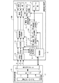
図8A,8Bは、本実施例に係る画像表示装置の機能構成の一例を示すブロック図である。図8Aでは、本実施例に係る画像表示装置100は、情報処理装置13を含む画像表示システムにおいて使用される。図8Bでは、本実施例に係る画像表示装置1002が、図8Aの情報処理装置13の機能をさらに有する。
8A and 8B are block diagrams showing an example of the functional configuration of the image display device according to the present embodiment. In FIG. 8A, the
以下では、図8Aの画像表示システムについて詳しく説明する。図8Bの画像表示装置1002で行われる処理は、図8Aの画像表示システムで行われる処理と同様であるため、図8Bの画像表示装置1002についての詳しい説明は省略する。図8Aに示すように、画像表示装置100は、実施例1の画像表示装置1が有する複数の機能部と、LPF処理部102とを有する。
The image display system of FIG. 8A will be described in detail below. Since the processing performed by the
制御部5は、実施例1と同様に、レンジ情報の取得、領域情報の取得、及び、HDR分割領域の検出を行う。そして、制御部5は、実施例1と同様に、レンジ情報を、BL輝度
決定部6、補正パラメータ決定部9、及び、階調特性変換部11に出力する。但し、本実施例では、制御部5は、HDR分割領域の検出結果を、少なくともBL輝度決定部6に出力する。詳細は後述するが、本実施例では、BL輝度決定部6により決定された各発光領域の発光輝度は、LPF処理部102により補正される。制御部5は、各発光領域の補正輝度(補正後の発光輝度)をLPF処理部102から取得し、各発光領域の補正輝度に基づいてHDR分割領域の検出結果を補正する。そして、制御部5は、HDR分割領域の補正結果(補正後の検出結果)を、補正パラメータ決定部9、合成部10、及び、階調特性変換部11に出力する。その結果、補正パラメータ決定部9、合成部10、及び、階調特性変換部11では、HDR分割領域の検出結果として補正後の検出結果を用いて、実施例1と同様の処理が行われる。
The
本実施例では、補正輝度が第1の輝度レンジの外側の輝度である発光領域に対応する分割領域をHDR分割領域として用いて対象画像データの補正が行われるように、HDR分割領域の検出結果が補正される。即ち、補正輝度が第1の輝度レンジの外側の輝度である発光領域に対応する分割領域がHDR分割領域として設定され、かつ、残りの分割領域が非HDR分割領域として設定されるように、HDR分割領域の検出結果が補正される。 In this embodiment, the detection result of the HDR divided region is performed so that the target image data is corrected by using the divided region corresponding to the light emitting region whose corrected brightness is the brightness outside the first luminance range as the HDR divided region. Is corrected. That is, HDR is set so that the divided region corresponding to the light emitting region whose correction brightness is the brightness outside the first luminance range is set as the HDR divided region and the remaining divided region is set as the non-HDR divided region. The detection result of the divided area is corrected.
HDR分割領域の非補正結果(補正前の検出結果)が図3(C)に示す結果であり、かつ、補正輝度が図9に示す発光輝度である場合の例を説明する。実施例1と同様に、第1の輝度レンジの最大輝度は、20%である。図9では、(6,1)〜(6,4)、(7,1)〜(7,4)、(8,1)〜(8,4)、(9,1)〜(9,4)、及び、(10,1)〜(10,4)の20個の発光領域の発光輝度が20%を超えている。そのため、これら20個の発光領域に対応する分割領域がHDR分割領域として設定され、かつ、残りの分割領域が非HDR分割領域として設定されるように、HDR分割領域の検出結果が補正される。上記20個の発光領域に対応する分割領域は、(6,1)〜(6,4)、(7,1)〜(7,4)、(8,1)〜(8,4)、(9,1)〜(9,4)、及び、(10,1)〜(10,4)の20個の分割領域である。図3(C)では、(7,1)〜(7,3)、(8,1)〜(8,3)、及び、(9,1)〜(9,3)の9個の分割領域がHDR分割領域として設定されており、残りの分割領域が非HDR分割領域として設定されている。そのため、検出結果の補正により、(6,1)〜(6,4)、(7,4)、(8,4)、(9,4)、(10,1)〜(10,4)の11個の分割領域が、非HDR分割領域からHDR分割領域に変更される。 An example will be described in which the non-correction result (detection result before correction) of the HDR division region is the result shown in FIG. 3C and the correction brightness is the emission brightness shown in FIG. Similar to Example 1, the maximum luminance of the first luminance range is 20%. In FIG. 9, (6,1) to (6,4), (7,1) to (7,4), (8,1) to (8,4), (9,1) to (9,4) ), And the emission brightness of the 20 light emitting regions of (10, 1) to (10, 4) exceeds 20%. Therefore, the detection result of the HDR divided region is corrected so that the divided region corresponding to these 20 light emitting regions is set as the HDR divided region and the remaining divided region is set as the non-HDR divided region. The divided regions corresponding to the above 20 light emitting regions are (6,1) to (6,4), (7,1) to (7,4), (8,1) to (8,4), ( There are 20 divided regions of 9,1) to (9,4) and (10,1) to (10,4). In FIG. 3C, nine divided regions (7,1) to (7,3), (8,1) to (8,3), and (9,1) to (9,3) Is set as the HDR division area, and the remaining division area is set as the non-HDR division area. Therefore, by correcting the detection result, (6,1) to (6,4), (7,4), (8,4), (9,4), (10,1) to (10,4) Eleven division areas are changed from non-HDR division areas to HDR division areas.
なお、HDR分割領域の検出結果の補正は省略されてもよい。しかし、上記方法でHDR分割領域を補正すれば、BLモジュール部3からの光を有効利用して、HDR表示が行われる領域を拡大することができる。その結果、より高画質な画像をユーザに提供することができる。また、HDR分割領域として設定するか否かの閾値は、第1の輝度レンジの最大輝度や最小輝度に限らない。
The correction of the detection result of the HDR division region may be omitted. However, if the HDR division region is corrected by the above method, the region where the HDR display is performed can be expanded by effectively utilizing the light from the
BL輝度決定部6は、実施例1と同様の方法で、各発光領域の発光輝度を決定する。但し、本実施例では、BL輝度決定部6は、各発光領域の発光輝度を示す情報を、BL制御値決定部7ではなく、LPF処理部102に出力する。
The BL
LPF処理部102は、BL輝度決定部6によって決定された各発光領域の発光輝度に対し、空間的LPF処理を施す。それにより、各発光領域の発光輝度が補正される。LPF処理部102は、各発光領域の補正輝度(補正後の発光輝度)を示す情報を、制御部5とBL制御値決定部7に出力する。
The
空間的LPF処理の一例を説明する。まず、LFP処理部102は、対象発光領域Nの周囲に存在する複数の発光領域から、発光輝度が最も高い発光領域Max(N)を検出す
る。例えば、対象発光領域Nの周囲に存在する発光領域は、対象発光領域Nからの距離が閾値以下の発光領域である。本実施例では、対象発光領域Nに隣接する複数の発光領域から、発光領域Max(N)が検出される。なお、閾値として、2個以上の発光領域に相当する値が使用されてもよい。即ち、対象発光領域Nに隣接する発光領域よりも外側の発光領域が、対象発光領域Nの周囲に存在する発光領域としてさらに使用されてもよい。
An example of spatial LPF processing will be described. First, the
次に、LPF処理部102は、対象発光領域Nの発光輝度L(N)を、発光領域Max(N)の発光輝度L(Max(N))に係数αを乗算した値と比較する。α×L(Max(N))がL(N)よりも高い場合には、LPF処理部102は、対象発光領域Nの発光輝度をL(N)からα×L(Max(N))に置き換える。α×L(Max(N))がL(N)以下である場合には、LPF処理部102は、対象発光領域Nの発光輝度の置き換えを行わない。
Next, the
LPF処理部102は、複数の発光領域のそれぞれを対象発光領域Nとして選択し、上述した処理を行う。α=0.5の場合には、図5(C)に示す分布は図9に示す分布に補正される。
The
なお、係数αは、0.5より大きくても小さくてもよい。係数αは、発光領域からの光の拡散度合い、発光領域の発光輝度の変動量、等に基づいて決定または変更されてもよい。また、空間的LPF処理は上記処理に限らない。空間的LPF処理として、値の分布をなだらかにする種々の従来技術を使用することができる。 The coefficient α may be larger or smaller than 0.5. The coefficient α may be determined or changed based on the degree of diffusion of light from the light emitting region, the amount of fluctuation in the light emission brightness in the light emitting region, and the like. Further, the spatial LPF processing is not limited to the above processing. As the spatial LPF processing, various conventional techniques for smoothing the distribution of values can be used.
以上述べたように、本実施例でも、HDR表示が行われる領域がHDR分割領域に制限される。そのため、HDR表示の際の画像表示装置の消費電力と、HDR表示を確認する際のユーザの疲労感とを低減することができる。また、HDR表示が行われた画面の領域がユーザに通知される。これにより、HDR表示が行われた領域と、それ以外の領域とをユーザが容易に把握可能となる。さらに、本実施例によれば、複数の発光領域の発光輝度の分布が平滑化される。それにより、表示画像の画質の劣化(ハローの発生、動画表示時におけるフリッカの発生、等)を抑制することができる。 As described above, also in this embodiment, the area where the HDR display is performed is limited to the HDR division area. Therefore, it is possible to reduce the power consumption of the image display device at the time of HDR display and the feeling of fatigue of the user when confirming the HDR display. In addition, the user is notified of the area of the screen on which the HDR display is performed. As a result, the user can easily grasp the area where the HDR display is performed and the other area. Further, according to this embodiment, the distribution of emission luminance in a plurality of emission regions is smoothed. As a result, deterioration of the image quality of the displayed image (generation of halo, occurrence of flicker when displaying a moving image, etc.) can be suppressed.
<実施例3>
以下、本発明の実施例3に係る画像表示装置について説明する。なお、以下では、実施例1と異なる構成や処理について詳しく説明し、実施例1と同様の構成や処理についての説明は省略する。以下では、本実施例の特徴的な構成を実施例1の構成に適用した例を説明するが、本実施例の特徴的な構成は実施例2の構成にも適用可能である。
<Example 3>
Hereinafter, the image display device according to the third embodiment of the present invention will be described. In the following, the configurations and processes different from those of the first embodiment will be described in detail, and the description of the same configurations and processes as in the first embodiment will be omitted. Hereinafter, an example in which the characteristic configuration of the present embodiment is applied to the configuration of the first embodiment will be described, but the characteristic configuration of the present embodiment can also be applied to the configuration of the second embodiment.
実施例1,2では、HDR表示が行われた画面の領域がユーザに通知される。しかしながら、各発光領域からの光は周囲に拡散する。そのため、HDR表示が行われた領域の周囲の領域において、HDR表示を行わない場合の照射輝度を大きく上回る輝度に照射輝度が制御されることがある。その結果、HDR表示が行われた領域の周囲の領域において、正確な輝度(所望の輝度)の表示ができないことがある。特に、低階調値を正確な輝度で表示できない可能性が高い。そこで、本実施例では、正確な輝度で表示できない可能性が高い領域(影響領域)をユーザに通知する。それにより、ユーザが影響領域を容易に把握可能となり、影響領域の輝度が正確な輝度であるとのユーザの誤認を防ぐことができる。 In the first and second embodiments, the user is notified of the area of the screen on which the HDR display is performed. However, the light from each light emitting region is diffused to the surroundings. Therefore, in the region around the region where the HDR display is performed, the irradiation brightness may be controlled to a brightness that greatly exceeds the irradiation brightness when the HDR display is not performed. As a result, accurate brightness (desired brightness) may not be displayed in the area around the area where HDR display is performed. In particular, there is a high possibility that low gradation values cannot be displayed with accurate brightness. Therefore, in this embodiment, the user is notified of an area (affected area) that is likely to be unable to be displayed with accurate brightness. As a result, the user can easily grasp the affected area, and it is possible to prevent the user from misunderstanding that the brightness of the affected area is an accurate brightness.
図10A,10Bは、本実施例に係る画像表示装置の機能構成の一例を示すブロック図である。図10Aでは、本実施例に係る画像表示装置200は、情報処理装置13を含む画像表示システムにおいて使用される。図10Bでは、本実施例に係る画像表示装置1003が、図10Aの情報処理装置13の機能をさらに有する。
10A and 10B are block diagrams showing an example of the functional configuration of the image display device according to the present embodiment. In FIG. 10A, the
以下では、図10Aの画像表示システムについて詳しく説明する。図10Bの画像表示装置1003で行われる処理は、図10Aの画像表示システムで行われる処理と同様であるため、図10Bの画像表示装置1003についての詳しい説明は省略する。図10Aに示すように、画像表示装置200は、実施例1の画像表示装置1が有する複数の機能部と、高輝度領域検出部201とを有する。
The image display system of FIG. 10A will be described in detail below. Since the processing performed by the
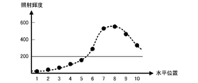
高輝度領域検出部201は、照射輝度の推定結果を輝度推定部8から取得し、照射輝度が閾値以上である画面の領域を高輝度領域として検出する。高輝度領域検出部201は、高輝度領域の検出結果を、制御部5に出力する。図11は、推定された照射輝度の分布の一例を示す。図11の横軸は水平位置を示し、図11の縦軸は照射輝度を示す。図11の黒丸は、推定位置における照射輝度を示し、図11の破線は、推定位置の照射輝度の補間結果を示す。ここでは、説明の簡略化のために、水平方向における照射輝度分布を用いて高輝度領域の検出方法を説明する。閾値が200である場合には、水平位置が6〜10の5つの分割領域が、高輝度領域として検出される。
The high-luminance
なお、照射輝度と比較される閾値は、メーカーによって予め定められた固定値であってもよいし、ユーザが変更可能な値であってもよい。対象画像データの種類、画像表示装置の使用環境(周囲の明るさ等)、等に応じて閾値が自動で決定されてもよい。各発光領域の個別制御(ローカルデミング処理)を行わない場合、全ての発光領域の発光輝度は基準輝度に制御される。照射輝度と比較される閾値として、全ての発光領域の発光輝度を基準輝度に制御した場合の照射輝度が使用されてもよい。照射輝度と比較される閾値として、第1の輝度レンジの最大輝度が使用されてもよい。SDRでの表示が行われるようにローカルデミング処理を行った場合に取り得る照射輝度の最大値が、照射輝度と比較される閾値として使用されてもよい。 The threshold value to be compared with the irradiation brightness may be a fixed value predetermined by the manufacturer or a value that can be changed by the user. The threshold value may be automatically determined according to the type of the target image data, the usage environment of the image display device (ambient brightness, etc.), and the like. When the individual control (local deming process) of each light emitting region is not performed, the light emitting brightness of all the light emitting regions is controlled to the reference brightness. As the threshold value to be compared with the irradiation brightness, the irradiation brightness when the emission brightness of all the light emitting regions is controlled to the reference brightness may be used. The maximum brightness of the first brightness range may be used as the threshold value to be compared with the irradiation brightness. The maximum value of the irradiance that can be taken when the local deming process is performed so as to be displayed in SDR may be used as a threshold value to be compared with the irradiance.
制御部5は、実施例1と同様の処理を行う。さらに、制御部5は、高輝度領域の検出結果を高輝度領域検出部201から取得する。そして、制御部5は、高輝度領域から対応分割領域を除いた領域を影響領域として検出し、影響領域の検出結果を合成部10に出力する。例えば、図11において、水平位置が6〜10の5つの分割領域が高輝度領域であり、かつ、水平位置が7〜9の3つの分割領域がHDR分割領域である場合を考える。この場合、制御部5は、HDR分割領域の検出結果として、水平位置が7〜9の3つの分割領域を示す情報を出力し、影響領域の検出結果として、水平位置が6と10の2つの分割領域を示す情報を出力する。
The
合成部10は、第1の合成と第2の合成とを行う。第1の合成は、補正後の対象画像データに基づく画像に加え、第1のグラフィック画像がさらに表示されるように、HDR分割領域の検出結果に基づいて、第1のグラフィック画像を表す第1のグラフィック画像データを合成する処理である。第2の合成は、補正後の対象画像データに基づく画像に加え、第2のグラフィック画像がさらに表示されるように、影響領域の検出結果に基づいて、第2のグラフィック画像を表す第2のグラフィック画像データを合成する処理である。それにより、対象画像データに第1のグラフィック画像データと第2のグラフィック画像データを合成した合成画像データが生成される。合成部10は、合成画像データを階調特性変換部11に出力する。なお、第1の合成は省略されてもよい。
The
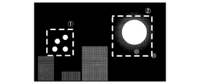
第1のグラフィック画像は、HDR表示領域を示すグラフィック画像であり、第2のグラフィック画像は、影響領域を示す画像である。図12は、合成画像データに基づく画像(合成画像)の一例を示す。図12において、破線301は第1のグラフィック画像であり、ハッチング画像302は第2のグラフィック画像である。第1のグラフィック画像が表示されることにより、HDR表示領域がユーザに通知され、第2のグラフィック画像が表示されることにより、影響領域がユーザに通知される。換言すれば、ユーザは、表示さ
れた第1のグラフィック画像を確認することにより、HDR表示領域を把握することができ、表示された第2のグラフィック画像を確認することにより、影響領域を把握することができる。
The first graphic image is a graphic image showing an HDR display area, and the second graphic image is an image showing an affected area. FIG. 12 shows an example of an image (composite image) based on the composite image data. In FIG. 12, the
なお、照射輝度は、各発光領域の発光輝度(BL制御値)に基づいて推定され、影響領域は、HDR分割領域の検出結果と、推定された照射輝度の分布とに基づいて検出される。そのため、第2の合成は、「HDR分割領域の検出結果と、各発光領域の発光輝度とに基づいて、第2のグラフィック画像データを合成する処理」と言うこともできる。 The irradiance is estimated based on the irradiance (BL control value) of each light emitting region, and the affected area is detected based on the detection result of the HDR division region and the estimated distribution of the irradiance. Therefore, the second composition can be said to be "a process of synthesizing the second graphic image data based on the detection result of the HDR divided region and the emission brightness of each light emitting region".
なお、第1のグラフィック画像と第2のグラフィック画像は、図12に示す画像に限らない。HDR表示領域をユーザに通知できれば、どのような画像が第1のグラフィック画像として使用されてもよい。影響領域をユーザに通知できれば、どのような画像が第2のグラフィック画像として使用されてもよい。例えば、HDR表示領域を示すメッセージ画像が第1のグラフィック画像として使用されてもよい。具体的には、「右半面でHDR表示が行われます。」、「HDR表示領域の始点座標はAであり、終点座標はBです。」等のメッセージ画像が第1のグラフィック画像として使用されてもよい。画面を意味し、かつ、HDR表示領域に対応する領域が他の領域と区別されたグラフィック画像が、第1のグラフィック画像として使用されてもよい。影響領域を示すメッセージ画像が第2のグラフィック画像として使用されてもよい。画面を意味し、かつ、影響領域に対応する領域が他の領域と区別されたグラフィック画像が、第2のグラフィック画像として使用されてもよい。所定の透明度と、所定の色とを有する画像が、影響領域に重ねられる第2のグラフィック画像として使用されてもよい。 The first graphic image and the second graphic image are not limited to the image shown in FIG. Any image may be used as the first graphic image as long as the HDR display area can be notified to the user. Any image may be used as the second graphic image as long as the affected area can be notified to the user. For example, a message image indicating the HDR display area may be used as the first graphic image. Specifically, message images such as "HDR display is performed on the right half surface" and "The start point coordinates of the HDR display area are A and the end point coordinates are B" are used as the first graphic image. You may. A graphic image that means a screen and in which the area corresponding to the HDR display area is distinguished from other areas may be used as the first graphic image. A message image showing the affected area may be used as the second graphic image. A graphic image that means a screen and whose area corresponding to the affected area is distinguished from other areas may be used as the second graphic image. An image having a predetermined transparency and a predetermined color may be used as a second graphic image superimposed on the affected area.
以上述べたように、本実施例によれば、影響領域がユーザに通知される。それにより、ユーザが影響領域を容易に把握可能となり、影響領域の輝度が正確な輝度であるとのユーザの誤認を防ぐことができる。 As described above, according to the present embodiment, the affected area is notified to the user. As a result, the user can easily grasp the affected area, and it is possible to prevent the user from misunderstanding that the brightness of the affected area is an accurate brightness.
<実施例4>
以下、本発明の実施例4に係る画像表示装置について説明する。なお、以下では、実施例1〜3と異なる構成や処理について詳しく説明し、実施例1〜3と同様の構成や処理についての説明は省略する。
<Example 4>
Hereinafter, the image display device according to the fourth embodiment of the present invention will be described. In the following, configurations and processes different from those of Examples 1 to 3 will be described in detail, and description of the same configurations and processes as those of Examples 1 to 3 will be omitted.
実施例1〜3では、ユーザがHDR表示を望む領域を指定し、指定された領域に対応する発光領域の発光輝度を他の発光領域の発光輝度に比べて高い輝度に制御し、HDR表示が行われる領域をユーザに通知した。ここで、「他の発光領域」は、「SDR表示領域(指定された領域以外の領域;SDR表示が行われる領域)に対応する発光領域」である。 In the first to third embodiments, the region in which the user desires the HDR display is designated, the emission brightness of the light emitting region corresponding to the designated region is controlled to be higher than the emission brightness of the other light emitting regions, and the HDR display is displayed. Notified the user of the area to be done. Here, the "other light emitting area" is a "light emitting area corresponding to the SDR display area (area other than the designated area; the area where the SDR display is performed)".
本実施例では、入力画像データの特徴量から、HDR表示を行うべき領域(本実施例では「HDR推奨領域」と呼ぶ)を検出し、HDR推奨領域をユーザに通知する。そして、HDR推奨領域が通知された後に、HDR推奨領域でのHDR表示の実行がユーザによって指示されると、HDR推奨領域でのHDR表示を行う。HDR推奨領域でのHDR表示の実行の指示は、ユーザI/F部(ユーザインターフェース部)を介して受信される。これにより、ユーザがHDR表示画像(HDR表示が行われた領域における表示画像)の確認の見落としなどを防止することができ、HDR表示とSDR表示が1画面に混在している場合の表示画像の画質確認作業の利便性を向上することができる。 In this embodiment, an area to be displayed in HDR (referred to as an “HDR recommended area” in this embodiment) is detected from the feature amount of the input image data, and the HDR recommended area is notified to the user. Then, after the HDR recommended area is notified, when the user is instructed to execute the HDR display in the HDR recommended area, the HDR display is performed in the HDR recommended area. The instruction to execute the HDR display in the HDR recommended area is received via the user I / F unit (user interface unit). This makes it possible for the user to prevent the user from overlooking the confirmation of the HDR display image (display image in the area where the HDR display is performed), and the display image when the HDR display and the SDR display are mixed on one screen. The convenience of image quality confirmation work can be improved.
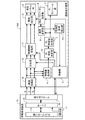
図13は、本実施例に係る画像表示装置300の機能構成の一例を示すブロック図である。図13に示すように、画像表示装置300は、実施例1の画像表示装置1が有する複数の機能部、HDR推奨領域検出部301、及び、ユーザI/F部302を有する。
FIG. 13 is a block diagram showing an example of the functional configuration of the
HDR推奨領域検出部301は、各分割領域の輝度特徴量に基づいて、複数の分割領域から、HDR画素を含む分割領域を、HDR推奨領域(特定領域)として検出する。そして、HDR推奨領域検出部301は、HDR推奨領域の検出結果を制御部5へ出力する。「HDR画素」は、「HDR(第2のダイナミックレンジ)を有する画素」である。そして、「HDR画素を含む分割領域」は、「HDR画素を含む画像データに対応する分割領域」である。「HDR画素を含む分割領域」は、「HDR画素が存在する分割領域」と言うこともできる。
The HDR recommended
本実施例では、輝度特徴量として最大階調値が使用される。HDR推奨領域検出部301は、制御部5から、SDRと、SDRに属さず且つHDRに属す階調値の範囲との境界に対応する階調値(境界階調値)の情報を受信する。HDR、境界階調値、等は、例えば、入力画像データのフォーマットに応じて規定される。HDR推奨領域検出部301は、各分割領域の輝度特徴量(最大階調値)を、取得した境界階調値と比較する。そして、HDR推奨領域検出部301は、輝度特徴量(最大階調値)が境界階調値よりも大きい分割領域をHDR推奨領域として決定する。
In this embodiment, the maximum gradation value is used as the luminance feature amount. The HDR recommended
なお、輝度特徴量は最大階調値に限られない。例えば、階調値のヒストグラムが輝度特徴量として使用されてもよい。ヒストグラムが使用される場合には、複数の分割領域のうち、含まれるHDR画素の数が最も多い分割領域が、HDR推奨領域として検出されてもよい。含まれるHDR画素の数が所定数以上である全ての分割領域が、HDR推奨領域として検出されてもよい。HDR推奨領域からの距離が閾値以下であり、且つ、HDR画素を含む分割領域が、HDR推奨領域としてさらに検出されてもよい。例えば、HDR推奨領域に隣接し、且つ、HDR画素を含む分割領域が、HDR推奨領域としてさらに検出されてもよい。 The luminance feature amount is not limited to the maximum gradation value. For example, a histogram of gradation values may be used as a luminance feature amount. When the histogram is used, the divided region having the largest number of HDR pixels among the plurality of divided regions may be detected as the HDR recommended region. All the divided regions in which the number of HDR pixels included is a predetermined number or more may be detected as the HDR recommended region. A divided region in which the distance from the HDR recommended region is equal to or less than the threshold value and includes HDR pixels may be further detected as the HDR recommended region. For example, a divided region adjacent to the HDR recommended region and including the HDR pixel may be further detected as the HDR recommended region.
ユーザI/F部302は、ユーザ操作(ユーザからの指示)を受け付ける。そして、ユーザI/F部302は、ユーザからの指示に応じた情報を制御部5へ出力する。例えば、ユーザI/F部302は、レンジ情報に関する指示をユーザから受け付け、レンジ情報を制御部5へ出力する。「レンジ情報に関する指示」は、例えば、「HDRの指定」である。
The user I /
本実施例の制御部5は、ユーザI/F部302からレンジ情報を取得し、特徴量取得部4から各分割領域の輝度特徴量を取得し、HDR推奨領域検出部301からHDR推奨領域の検出結果を取得する。そして、制御部5は、HDR推奨領域をユーザに通知するために、合成部10にHDR推奨領域の検出結果(HDR推奨領域の座標など)を通知する。合成部10は、HDR推奨領域の検出結果がグラフィック画像で表示されるように、当該グラフィック画像を表すグラフィック画像データの合成を行う。例えば、グラフィック画像データは、補正前の対象画像データ(入力画像データ)に合成される。それにより、補正前の対象画像データにグラフィック画像データを合成した合成画像データが生成される。そして、合成部10は、合成画像データを階調特性変換部11に出力する。
The
なお、グラフィック画像データが合成される画像データは特に限定されない。画面全体でSDR表示が行われるように補正された後の対象画像データに、グラフィック画像データが合成されてもよい。 The image data to which the graphic image data is combined is not particularly limited. Graphic image data may be combined with the target image data after being corrected so that the SDR display is performed on the entire screen.
グラフィック画像は、例えば、図3(B)の破線131のような画像(矩形の枠画像)である。グラフィック画像が表示されることにより、HDR推奨領域がユーザに通知される。換言すれば、ユーザは、表示されたグラフィック画像を確認することにより、HDR推奨領域、HDR推奨領域の有無、等を把握することができる。
The graphic image is, for example, an image (rectangular frame image) as shown by the
グラフィック画像が表示された後に、ユーザは、画像表示装置300(ユーザI/F部302)に対して、HDR推奨領域においてHDR表示を行うか否かに関する指示を行うことができる。「HDR推奨領域においてHDR表示を行うか否かに関する指示」は、「HDR推奨領域においてHDR表示を行うことの指示」、「HDR推奨領域においてHDR表示を行わないことの指示」、等である。なお、HDR推奨領域においてHDR表示を行うことの指示と、HDR推奨領域においてHDR表示を行わないことの指示との一方は積極的に行われなくてもよい。HDR推奨領域においてHDR表示を行うことの指示が行われなかった場合に、HDR推奨領域においてHDR表示を行わないことの指示が行われたと判断されてもよい。HDR推奨領域においてHDR表示を行わないことの指示が行われなかった場合に、HDR推奨領域においてHDR表示を行わうことの指示が行われたと判断されてもよい。 After the graphic image is displayed, the user can instruct the image display device 300 (user I / F unit 302) whether or not to perform HDR display in the HDR recommended area. The "instruction regarding whether or not to perform HDR display in the HDR recommended area" is "instruction to perform HDR display in the HDR recommended area", "instruction not to perform HDR display in the HDR recommended area", and the like. It should be noted that one of the instruction to display the HDR in the HDR recommended area and the instruction not to display the HDR in the HDR recommended area may not be positively given. When the instruction not to display HDR in the HDR recommended area is not given, it may be determined that the instruction not to perform HDR display is given in the HDR recommended area. When the instruction not to perform the HDR display is given in the HDR recommended area, it may be determined that the instruction to perform the HDR display is given in the HDR recommended area.
HDR推奨領域においてHDR表示を行うか否かに関する指示が行われると、当該指示に応じた情報が、ユーザI/F部302から制御部5へ出力される。制御部5は、ユーザI/F部502からの情報に応じて、HDR推奨領域においてHDR表示を行うことの指示が行われたか否かを判断する。そして、制御部5は、HDR推奨領域においてHDR表示を行うことの指示が行われた場合に、実施例1と同様に、HDR推奨領域の検出結果とレンジ情報とを、BL輝度決定部6、補正パラメータ決定部9、及び、階調特性変換部11に出力する。BL輝度決定部6、補正パラメータ決定部9、及び、階調特性変換部11では、実施例1と同様の処理が行われる。その結果、HDR推奨領域においてHDR表示を行うことの指示が行われた場合に、HDR推奨領域においてHDR表示が行われ、HDR推奨領域においてHDR表示を行うことの指示が行われなかった場合に、HDR推奨領域においてSDR表示が行われる。HDR推奨領域以外の領域ではSDR表示が行われる。
When an instruction as to whether or not to perform HDR display is given in the HDR recommended area, the information corresponding to the instruction is output from the user I /
なお、制御部5は、各分割領域の輝度特徴量からレンジ情報を生成してもよい。例えば、HDR推奨領域の輝度特徴量(最大階調値)の最大値がHDRに属す階調値の最大値として設定されるように、レンジ情報が生成されてもよい。
The
以上述べたように、本実施例によれば、HDR推奨領域(HDR表示を行うべき領域)が自動で検出されてユーザに通知され、その後のユーザからの指示に従ってHDR推奨領域での表示がHDR表示とSDR表示との間で切り替えられる。それにより、実施例1の効果が得られるとともに、ユーザがHDR表示画像の画質確認の見落としなどを防止できる。 As described above, according to the present embodiment, the HDR recommended area (the area where HDR display should be performed) is automatically detected and notified to the user, and the display in the HDR recommended area is displayed in HDR according to the subsequent instruction from the user. You can switch between display and SDR display. As a result, the effect of the first embodiment can be obtained, and the user can prevent the user from overlooking the image quality confirmation of the HDR display image.
なお、本実施例では、画像表示装置300の画面にグラフィック画像を表示することにより、HDR推奨領域をユーザに通知する例を示したが、これに限られない。例えば、外部装置(外部装置のアプリケーション)と連携することで、外部装置の画面にグラフィック画像を表示することにより、HDR推奨領域がユーザに通知されてもよい。外部装置は、例えば、タブレットPC、ワークスステーション、等である。
In this embodiment, an example is shown in which the HDR recommended area is notified to the user by displaying a graphic image on the screen of the
<実施例5>
以下、本発明の実施例5に係る画像表示装置について説明する。なお、以下では、実施例1〜4と異なる構成や処理について詳しく説明し、実施例1〜4と同様の構成や処理についての説明は省略する。
<Example 5>
Hereinafter, the image display device according to the fifth embodiment of the present invention will be described. In the following, configurations and processes different from those of Examples 1 to 4 will be described in detail, and description of the same configurations and processes as in Examples 1 to 4 will be omitted.
実施例4では、自動で検出されたHDR推奨領域がユーザに通知される。しかしながら、画像表示装置では、複数のHDR推奨領域が検出され場合に、「全てのHDR推奨領域においてHDR表示を行う」という処理(理想処理)を実行できないことがある。例えば、画像表示装置がバッテリーで駆動される場合などにおいては、電源容量が制限されるこ
とにより、理想処理を実行できないことがある。そこで、本実施例では、理想処理を実行すべきでなく、且つ、1つ以上のHDR推奨領域からなる領域である合成推奨領域(集合特定領域)が複数存在する場合に、複数の合成推奨領域のそれぞれに優先度(優先順位)を付ける。そして、ユーザに各合成推奨領域の優先度をさらに通知する。それにより、ユーザは、理想処理を実行できない(実行すべきでない)こと、優先的にHDR表示を行うべき合成推奨領域、等を把握することができる。その結果、理想処理を実行できない場合においても、ユーザは、HDR表示画像の画質確認の見落としなどを防止できる。
In the fourth embodiment, the user is notified of the automatically detected HDR recommended area. However, in the image display device, when a plurality of HDR recommended areas are detected, the process (ideal process) of "displaying HDR in all HDR recommended areas" may not be executed. For example, when the image display device is driven by a battery, the ideal process may not be executed due to the limitation of the power supply capacity. Therefore, in this embodiment, when the ideal process should not be executed and there are a plurality of synthesis recommended regions (set specific regions) which are regions consisting of one or more HDR recommended regions, a plurality of synthesis recommended regions are present. Give priority (priority) to each of. Then, the user is further notified of the priority of each synthesis recommended area. As a result, the user can grasp that the ideal process cannot be executed (should not be executed), the synthesis recommended area in which the HDR display should be preferentially performed, and the like. As a result, even when the ideal process cannot be executed, the user can prevent oversight of the image quality confirmation of the HDR display image.
図14は、本実施例に係る画像表示装置400の機能構成の一例を示すブロック図である。図14に示すように、画像表示装置400は、実施例4の画像表示装置300が有する複数の機能部、電力推定部401、及び、優先度決定部402を有する。
FIG. 14 is a block diagram showing an example of the functional configuration of the
電力推定部401は、画像表示装置400(BLモジュール部3)で使用される電力を推定する。例えば、電力推定部401は、全てのHDR推奨領域でHDR表示が行われた場合の電力を推定する。そして、電力推定部401は、電力の推定結果を優先度決定部402へ出力する。電力の推定方法は特に限定されない。BL制御値決定部7で決定されたBL制御値を使用すれば、電力を高精度に推定することができる。本実施例では、電力推定部401は、HDR推奨領域の検出結果、レンジ情報、及び、各分割領域の輝度特徴量から、電力を大まかに推定する。具体的には、BL輝度決定部6で決定される目標輝度が推定され、推定された目標輝度から電力が推定される。
The
各発光領域の目標輝度が図15(A)に示す値である場合を考える。ここでは、HDR表示を行わない場合の目標輝度の最大値、すなわちローカルデミング処理を行わない場合の目標輝度が10であるとする。図15(A)に示す目標輝度の総和は、1493である。一方、ローカルデミング処理が行われない場合の目標輝度の総和は、10×60(発光領域の数)=600である。そのため、図15(A)では、ローカルデミング処理が行われない場合の明るさの1493/600≒2.48倍の明るさで、BLモジュール部3が点灯する。そして、ローカルデミング処理が行われない場合のBLモジュール部3の電力をAとすると、図15(A)の場合における電力が2.48×Aであると推定することができる。
Consider the case where the target luminance in each light emitting region is the value shown in FIG. 15 (A). Here, it is assumed that the maximum value of the target luminance when the HDR display is not performed, that is, the target luminance when the local demming process is not performed is 10. The total sum of the target luminances shown in FIG. 15 (A) is 1493. On the other hand, the total target brightness when the local demming process is not performed is 10 × 60 (the number of light emitting regions) = 600. Therefore, in FIG. 15A, the
優先度決定部402は、HDR推奨領域の検出結果から、合成推奨領域を判断する。そして、複数の合成推奨領域が存在する場合に、優先度決定部402は、電力推定部401で推定された電力に基づいて、「全てのHDR推奨領域(全ての合成推奨領域)においてHDR表示を行う」という理想処理を行ってもよいか否かを判断する。理想処理を行ってもよいか否かは、画像表示装置400の電源仕様に依存する。そこで、本実施例では、優先度決定部402は、電力推定部401で推定された電力が閾値以上である場合に、理想処理を行ってもよいと判断する。なお、電力と比較される閾値は、メーカーによって予め定められた固定値であってもよいし、画像表示装置400の状態、ユーザからの指示、等に応じて変更される値であってもよい。
The
そして、理想処理を行うべきでないと判断された場合に、優先度決定部402は、各合成推奨領域の優先度を決定し、各合成推奨領域の優先度を制御部5へ出力する。本実施例では、各合成推奨領域のサイズに基づいて優先度が決定される。合成推奨領域のサイズが小さいほど、当該合成推奨領域に含まれる全てのHDR推奨領域においてHDR表示を行うことのできる可能性が高い。そのため、優先度決定部402は、合成推奨領域のサイズが小さいほど高い優先度を決定する。各発光領域(各分割領域)の目標輝度が図15(A)に示す値である場合には、図15(B)に示すように、2つの合成推奨領域450,451が判断される。そして、合成推奨領域450には9つの分割領域が含まれ、合成推奨領域451には4つの分割領域が含まれる。そのため、合成推奨領域451の優先度とし
て、合成推奨領域450の優先度よりも高い優先度が決定される。
Then, when it is determined that the ideal processing should not be performed, the
本実施例の制御部5は、実施例1〜4で説明した制御と同様の制御を行う。但し、各合成推奨領域の優先度が優先度決定部402から出力された場合に、本実施例の制御部5は、HDR推奨領域に加え優先度をユーザに通知するために、合成部10に対して、HDR推奨領域の検出結果と、各合成推奨領域の優先度とを通知する。合成部10は、HDR推奨領域の検出結果と、各合成推奨領域の優先度とがグラフィック画像で表示されるように、当該グラフィック画像を表すグラフィック画像データの合成を行う。例えば、グラフィック画像データは、補正前の対象画像データに合成される。それにより、補正前の対象画像データにグラフィック画像データを合成した合成画像データが生成される。そして、合成部10は、合成画像データを階調特性変換部11に出力する。
The
なお、グラフィック画像データが合成される画像データは特に限定されない。画面全体でSDR表示が行われるように補正された後の対象画像データに、グラフィック画像データが合成されてもよい。 The image data to which the graphic image data is combined is not particularly limited. Graphic image data may be combined with the target image data after being corrected so that the SDR display is performed on the entire screen.
グラフィック画像は、例えば、図16の破線のような画像(矩形の枠画像)と番号を含む画像である。図16に記載の番号1,2は、優先度に対応する優先順位である。優先順位1に対応する破線は、図15(B)の合成推奨領域450を示し、優先順位2に対応する破線は、合成推奨領域451を示す。グラフィック画像が表示されることにより、HDR推奨領域(合成推奨領域)がユーザに通知される。換言すれば、ユーザは、表示されたグラフィック画像を確認することにより、HDR推奨領域、HDR推奨領域の有無、等を把握することができる。また、グラフィック画像が表示されることにより、各合成推奨領域の優先度がユーザに通知される。換言すれば、ユーザは、表示されたグラフィック画像を確認することにより、各合成推奨領域の優先度などを把握することができる。また、理想処理を実行すべきでないと判断された場合に優先度が通知されるため、ユーザは、表示されたグラフィック画像を確認することにより、理想処理を実行すべきでないことを把握することもできる。
The graphic image is, for example, an image including an image (rectangular frame image) such as a broken line in FIG. 16 and a number.
なお、HDR推奨領域の検出結果と、各合成推奨領域の優先度とを示すグラフィック画像が表示された後の処理は特に限定されない。例えば、HDR推奨領域においてHDR表示を行う指示に応じて、理想処理が行われてもよいし、優先度が最も高い合成推奨領域でのみHDR表示を行う処理が行われてもよい。HDR表示を行うことができる数の合成推奨領域が優先度から高い方から順番に選択され、選択された合成推奨領域でのみHDR表示を行う処理が行われてもよい。ユーザI/F部302が、HDR表示を行う合成推奨領域と、HDR表示を行わない合成推奨領域とに関する指示をユーザから受け付け、当該指示に応じた処理が行われてもよい。具体的には、HDR表示を行う合成推奨領域としてユーザによって指定された合成推奨領域でのみHDR表示を行う処理が行われてもよい。
The processing after the graphic image showing the detection result of the HDR recommended region and the priority of each composite recommended region is displayed is not particularly limited. For example, the ideal process may be performed according to the instruction to display the HDR in the HDR recommended area, or the process to display the HDR may be performed only in the composite recommended area having the highest priority. A number of recommended synthesis areas capable of displaying HDR may be selected in order from the highest priority, and a process of displaying HDR may be performed only in the selected recommended synthesis area. The user I /
以上述べたように、本実施例によれば、複数の合成推奨領域が存在し、且つ、理想処理を実行すべきでない場合に、HDR推奨領域の検出結果だけでなく、各合成推奨領域の優先度がユーザに通知される。それにより、表示画像の画質確認作業の利便性をより向上することができる。具体的には、ユーザは、理想処理を実行できない(実行すべきでない)こと、優先的にHDR表示を行うべき合成推奨領域、等を把握することができる。その結果、理想処理を実行できない場合においても、ユーザは、HDR表示画像の画質確認の見落としなどを防止できる。 As described above, according to the present embodiment, when there are a plurality of recommended synthesis regions and the ideal process should not be executed, not only the detection result of the HDR recommended region but also the priority of each recommended synthesis region is given. The degree is notified to the user. As a result, the convenience of checking the image quality of the displayed image can be further improved. Specifically, the user can grasp that the ideal process cannot be executed (should not be executed), the synthesis recommended area in which the HDR display should be preferentially performed, and the like. As a result, even when the ideal process cannot be executed, the user can prevent oversight of the image quality confirmation of the HDR display image.
なお、本実施例では、合成推奨領域のサイズが小さいほど高い優先度を決定する例を説明したが、これに限られない。例えば、合成推奨領域のサイズが大きいほど高い優先度が決定されてもよいし、合成推奨領域のサイズが所定サイズに近いほど高い優先度が決定さ
れてもよい。合成推奨領域のサイズとは異なる情報に基づいて優先度が決定されてもよい。例えば、階調値のヒストグラムにおける度数の集中度合いに基づいて優先度が決定されてもよい。具体的には、度数の集中度合いが高いほど高い優先度、度数の集中度合いが低いほど高い優先度、度数が集中している階調値が所定の階調値に近いほど高い優先度、等が決定されてもよい。所定の階調値は、例えば、SDRに属さず且つHDRに属す階調値である。また、合成推奨領域の数が1つであり、且つ、理想処理を実行すべきでない場合に、理想処理を実行すべきでないことがグラフィック画像で通知されてもよい。
In this embodiment, the smaller the size of the recommended synthesis region, the higher the priority is determined, but the present invention is not limited to this. For example, the larger the size of the recommended synthesis region, the higher the priority may be determined, or the closer the size of the recommended synthesis region is to the predetermined size, the higher the priority may be determined. The priority may be determined based on information different from the size of the recommended synthesis area. For example, the priority may be determined based on the degree of concentration of frequencies in the histogram of gradation values. Specifically, the higher the concentration of frequencies, the higher the priority, the lower the concentration of frequencies, the higher the priority, the closer the gradation value in which the frequencies are concentrated to the predetermined gradation value, the higher the priority, etc. May be determined. The predetermined gradation value is, for example, a gradation value that does not belong to SDR and belongs to HDR. Further, when the number of recommended synthesis regions is one and the ideal processing should not be executed, a graphic image may be notified that the ideal processing should not be executed.
<その他の実施例>
本発明は、上述の実施例の1以上の機能を実現するプログラムを、ネットワーク又は記憶媒体を介してシステム又は装置に供給し、そのシステム又は装置のコンピュータにおける1つ以上のプロセッサーがプログラムを読出し実行する処理でも実現可能である。また、1以上の機能を実現する回路(例えば、ASIC)によっても実現可能である。
<Other Examples>
The present invention supplies a program that realizes one or more functions of the above-described embodiment to a system or device via a network or storage medium, and one or more processors in the computer of the system or device reads and executes the program. It can also be realized by the processing to be performed. It can also be realized by a circuit (for example, ASIC) that realizes one or more functions.
1,100,200,300,400,1001〜1003:画像表示装置
2:液晶パネル部 3:BLモジュール部 4:特徴量取得部 5:制御部
6:BL輝度決定部 7:BL制御値決定部 8:輝度推定部
9:補正パラメータ決定部 11:階調特性変換部 12:輝度補正部
13:情報処理装置 14:ネットワークI/F部 18:画像取得部
301:HDR推奨領域検出部 302:ユーザI/F部
401:電力推測部 402:HDR優先領域決定部
1,100,200,300,400,101-1003: Image display device 2: Liquid crystal panel unit 3: BL module unit 4: Feature amount acquisition unit 5: Control unit 6: BL brightness determination unit 7: BL control value determination unit 8: Luminance estimation unit 9: Correction parameter determination unit 11: Gradation characteristic conversion unit 12: Luminance correction unit 13: Information processing device 14: Network I / F unit 18: Image acquisition unit 301: HDR recommended area detection unit 302: User I / F section 401: Power estimation section 402: HDR priority region determination section
Claims (7)
前記発光手段からの光を変調することにより、入力画像に基づく表示画像を前記画面に表示する表示手段と、
前記複数の分割領域にそれぞれ対応する複数の輝度特徴量を、前記入力画像から取得する特徴量取得手段と、
第1のダイナミックレンジよりも広い第2のダイナミックレンジを示すレンジ情報を取得する第1の情報取得手段と、
前記画面に表示された前記表示画像の一部の画像領域であるHDR画像領域を示す領域情報を取得する第2の情報取得手段と、
前記領域情報に基づいて、前記複数の分割領域から、前記HDR画像領域に対応する分割領域であるHDR分割領域と、前記HDR画像領域に対応しない分割領域である非HDR分割領域とを検出する検出手段と、
前記複数の分割領域のそれぞれの輝度特徴量、前記レンジ情報、及び、前記HDR分割領域と前記非HDR分割領域の検出結果に基づいて、前記非HDR分割領域において前記第1のダイナミックレンジでの表示が行われ、かつ、前記HDR分割領域において前記第2のダイナミックレンジでの表示が行われるように、前記複数の発光領域のそれぞれの発光輝度の個別制御と、前記入力画像の階調変換とを行う制御手段と、
を有し、
前記制御手段は、前記表示画像とともに、前記HDR画像領域を示す第1のグラフィック画像、又は、前記HDR分割領域ではなくかつ前記発光手段から発せられて前記表示手段に照射される光の輝度が閾値以上である前記画面の領域を示す第2のグラフィック画像が表示されるように、前記入力画像と前記第1又は第2のグラフィック画像とを合成する合成手段を有する
ことを特徴とする画像表示装置。 A light emitting means having a plurality of light emitting regions corresponding to a plurality of divided regions constituting the screen,
A display means for displaying a display image based on an input image on the screen by modulating the light from the light emitting means.
A feature amount acquisition means for acquiring a plurality of luminance features corresponding to each of the plurality of divided regions from the input image, and
A first information acquisition means for acquiring range information indicating a second dynamic range wider than the first dynamic range, and
A second information acquisition means for acquiring area information indicating an HDR image area, which is a part of the display image displayed on the screen, and
Detection to detect an HDR divided region, which is a divided region corresponding to the HDR image region, and a non-HDR divided region, which is a divided region not corresponding to the HDR image region, from the plurality of divided regions based on the region information. Means and
Display in the first dynamic range in the non-HDR division region based on the respective luminance features of the plurality of division regions, the range information, and the detection results of the HDR division region and the non-HDR division region. The individual control of the emission luminance of each of the plurality of emission regions and the gradation conversion of the input image are performed so that the display is performed in the second dynamic range in the HDR division region. Control measures to be performed and
Have,
The control means, together with the display image, has a threshold value of the brightness of the first graphic image showing the HDR image region, or the light emitted from the light emitting means and not the HDR division region and applied to the display means. An image display device comprising a compositing means for synthesizing the input image and the first or second graphic image so that the second graphic image indicating the area of the screen as described above is displayed. ..
前記発光手段からの光を変調することにより、入力画像に基づく表示画像を前記画面に
表示する表示手段と、
前記複数の分割領域にそれぞれ対応する複数の輝度特徴量を、前記入力画像から取得する特徴量取得手段と、
第1のダイナミックレンジよりも広い第2のダイナミックレンジを示すレンジ情報を取得する第1の情報取得手段と、
前記画面に表示された前記表示画像の一部の画像領域であるHDR画像領域を示す領域情報を取得する第2の情報取得手段と、
前記領域情報に基づいて、前記複数の分割領域から、前記HDR画像領域に対応する分割領域であるHDR分割領域と、前記HDR画像領域に対応しない分割領域である非HDR分割領域とを検出する検出手段と、
前記複数の分割領域のそれぞれの輝度特徴量、前記レンジ情報、及び、前記HDR分割領域と前記非HDR分割領域の検出結果に基づいて、前記非HDR分割領域において前記第1のダイナミックレンジでの表示が行われ、かつ、前記HDR分割領域において前記第2のダイナミックレンジでの表示が行われるように、前記複数の発光領域のそれぞれの発光輝度の個別制御と、前記入力画像の階調変換とを行う制御手段と、
を有し、
前記制御手段は、
前記複数の分割領域のそれぞれの輝度特徴量、前記レンジ情報、及び、前記HDR分割領域と前記非HDR分割領域の検出結果に基づいて、前記複数の発光領域のそれぞれの発光輝度を決定する決定手段と、
前記レンジ情報、前記HDR分割領域と前記非HDR分割領域の検出結果、及び、前記複数の発光領域のそれぞれの発光輝度に基づいて、前記入力画像の階調変換を行う階調変換手段と、
を有し、
前記決定手段は、前記複数の発光領域のうち、前記非HDR分割領域に対応する発光領域の発光輝度を、前記第1のダイナミックレンジに対応して設定された第1の輝度レンジを用いて決定し、前記複数の発光領域のうち、前記HDR分割領域に対応する発光領域の発光輝度を、前記第2のダイナミックレンジに対応して設定された第2の輝度レンジを用いて決定し、
前記第1の輝度レンジと前記第2の輝度レンジの比は、前記第1のダイナミックレンジと前記第2のダイナミックレンジの比と一致する
ことを特徴とする画像表示装置。 A light emitting means having a plurality of light emitting regions corresponding to a plurality of divided regions constituting the screen,
By modulating the light from the light emitting means, a display image based on the input image is displayed on the screen.
Display means to display and
A feature amount acquisition means for acquiring a plurality of luminance features corresponding to each of the plurality of divided regions from the input image, and
A first information acquisition means for acquiring range information indicating a second dynamic range wider than the first dynamic range, and
A second information acquisition means for acquiring area information indicating an HDR image area, which is a part of the display image displayed on the screen, and
Detection to detect an HDR divided region, which is a divided region corresponding to the HDR image region, and a non-HDR divided region, which is a divided region not corresponding to the HDR image region, from the plurality of divided regions based on the region information. Means and
Display in the first dynamic range in the non-HDR division region based on the respective luminance features of the plurality of division regions, the range information, and the detection results of the HDR division region and the non-HDR division region. The individual control of the emission luminance of each of the plurality of emission regions and the gradation conversion of the input image are performed so that the display is performed in the second dynamic range in the HDR division region. Control measures to be performed and
Have,
The control means
A determination means for determining the emission brightness of each of the plurality of light emitting regions based on the respective luminance features of the plurality of divided regions, the range information, and the detection results of the HDR divided region and the non-HDR divided region. When,
A gradation conversion means that performs gradation conversion of the input image based on the range information, the detection results of the HDR divided region and the non-HDR divided region, and the emission brightness of each of the plurality of light emitting regions.
Have,
The determining means determines the emission brightness of the light emitting region corresponding to the non-HDR divided region among the plurality of light emitting regions by using the first luminance range set corresponding to the first dynamic range. Then, among the plurality of light emitting regions, the light emitting brightness of the light emitting region corresponding to the HDR divided region is determined using the second luminance range set corresponding to the second dynamic range.
Wherein the ratio of the first luminance range and the second luminance range, the first dynamic range and the ratio between images display you characterized in that matching of the second dynamic range.
前記複数の分割領域のそれぞれの輝度特徴量は、前記複数の分割領域のそれぞれに表示された表示画像の最大階調値である
ことを特徴とする請求項2に記載の画像表示装置。 The minimum luminance in the first luminance range coincides with the minimum luminance in the second luminance range.
The image display device according to claim 2 , wherein the luminance feature amount of each of the plurality of divided regions is the maximum gradation value of the display image displayed in each of the plurality of divided regions.
ことを特徴とする請求項2または3に記載の画像表示装置。 The gradation conversion estimates the irradiance brightness, which is the brightness of the light emitted from the light emitting means and irradiates the display means, based on the irradiance brightness of each of the plurality of light emitting regions, and the range information, the said. The second or third claim, wherein the process includes a process of correcting the gradation value of the input image based on the detection result of the HDR divided region and the non-HDR divided region and the estimation result of the irradiance. Image display device.
前記発光手段からの光を変調することにより、入力画像に基づく表示画像を前記画面に表示する表示手段と、
を有する画像表示装置の制御方法であって、
前記複数の分割領域にそれぞれ対応する複数の輝度特徴量を、前記入力画像から取得す
る特徴量取得ステップと、
第1のダイナミックレンジよりも広い第2のダイナミックレンジを示すレンジ情報を取得する第1の情報取得ステップと、
前記画面に表示された前記表示画像の一部の画像領域であるHDR画像領域を示す領域情報を取得する第2の情報取得ステップと、
前記領域情報に基づいて、前記複数の分割領域から、前記HDR画像領域に対応する分割領域であるHDR分割領域と、前記HDR画像領域に対応しない分割領域である非HDR分割領域とを検出する検出ステップと、
前記複数の分割領域のそれぞれの輝度特徴量、前記レンジ情報、及び、前記HDR分割領域と前記非HDR分割領域の検出結果に基づいて、前記非HDR分割領域において前記第1のダイナミックレンジでの表示が行われ、かつ、前記HDR分割領域において前記第2のダイナミックレンジでの表示が行われるように、前記複数の発光領域のそれぞれの発光輝度の個別制御と、前記入力画像の階調変換とを行う制御ステップと、
を有し、
前記制御ステップは、前記表示画像とともに、前記HDR画像領域を示す第1のグラフィック画像、又は、前記HDR分割領域ではなくかつ前記発光手段から発せられて前記表示手段に照射される光の輝度が閾値以上である前記画面の領域を示す第2のグラフィック画像が表示されるように、前記入力画像と前記第1又は第2のグラフィック画像とを合成する合成ステップを含む
ことを特徴とする画像表示装置の制御方法。 A light emitting means having a plurality of light emitting regions corresponding to a plurality of divided regions constituting the screen,
A display means for displaying a display image based on an input image on the screen by modulating the light from the light emitting means.
It is a control method of an image display device having
A feature amount acquisition step of acquiring a plurality of luminance features corresponding to each of the plurality of divided regions from the input image, and
The first information acquisition step of acquiring range information indicating a second dynamic range wider than the first dynamic range, and
A second information acquisition step of acquiring area information indicating an HDR image area, which is a part of the display image displayed on the screen, and
Detection to detect an HDR divided region, which is a divided region corresponding to the HDR image region, and a non-HDR divided region, which is a divided region not corresponding to the HDR image region, from the plurality of divided regions based on the region information. Steps and
Display in the first dynamic range in the non-HDR division region based on the respective luminance features of the plurality of division regions, the range information, and the detection results of the HDR division region and the non-HDR division region. The individual control of the emission luminance of each of the plurality of emission regions and the gradation conversion of the input image are performed so that the display is performed in the second dynamic range in the HDR division region. Control steps to perform and
Have,
In the control step, the brightness of the first graphic image showing the HDR image region or the light emitted from the light emitting means and not the HDR divided region and radiated to the display means is a threshold value together with the display image. An image display device comprising a compositing step of synthesizing the input image and the first or second graphic image so that the second graphic image indicating the area of the screen as described above is displayed. Control method.
前記発光手段からの光を変調することにより、入力画像に基づく表示画像を前記画面に表示する表示手段と、
を有する画像表示装置の制御方法であって、
前記複数の分割領域にそれぞれ対応する複数の輝度特徴量を、前記入力画像から取得する特徴量取得ステップと、
第1のダイナミックレンジよりも広い第2のダイナミックレンジを示すレンジ情報を取得する第1の情報取得ステップと、
前記画面に表示された前記表示画像の一部の画像領域であるHDR画像領域を示す領域情報を取得する第2の情報取得ステップと、
前記領域情報に基づいて、前記複数の分割領域から、前記HDR画像領域に対応する分割領域であるHDR分割領域と、前記HDR画像領域に対応しない分割領域である非HDR分割領域とを検出する検出ステップと、
前記複数の分割領域のそれぞれの輝度特徴量、前記レンジ情報、及び、前記HDR分割領域と前記非HDR分割領域の検出結果に基づいて、前記非HDR分割領域において前記第1のダイナミックレンジでの表示が行われ、かつ、前記HDR分割領域において前記第2のダイナミックレンジでの表示が行われるように、前記複数の発光領域のそれぞれの発光輝度の個別制御と、前記入力画像の階調変換とを行う制御ステップと、
を有し、
前記制御ステップは、
前記複数の分割領域のそれぞれの輝度特徴量、前記レンジ情報、及び、前記HDR分割領域と前記非HDR分割領域の検出結果に基づいて、前記複数の発光領域のそれぞれの発光輝度を決定する決定ステップと、
前記レンジ情報、前記HDR分割領域と前記非HDR分割領域の検出結果、及び、前記複数の発光領域のそれぞれの発光輝度に基づいて、前記入力画像の階調変換を行う階調変換ステップと、
を含み、
前記決定ステップでは、前記複数の発光領域のうち、前記非HDR分割領域に対応する
発光領域の発光輝度を、前記第1のダイナミックレンジに対応して設定された第1の輝度レンジを用いて決定し、前記複数の発光領域のうち、前記HDR分割領域に対応する発光領域の発光輝度を、前記第2のダイナミックレンジに対応して設定された第2の輝度レンジを用いて決定し、
前記第1の輝度レンジと前記第2の輝度レンジの比は、前記第1のダイナミックレンジと前記第2のダイナミックレンジの比と一致する
ことを特徴とする画像表示装置の制御方法。 A light emitting means having a plurality of light emitting regions corresponding to a plurality of divided regions constituting the screen,
A display means for displaying a display image based on an input image on the screen by modulating the light from the light emitting means.
It is a control method of an image display device having
A feature amount acquisition step of acquiring a plurality of luminance features corresponding to each of the plurality of divided regions from the input image, and
The first information acquisition step of acquiring range information indicating a second dynamic range wider than the first dynamic range, and
A second information acquisition step of acquiring area information indicating an HDR image area, which is a part of the display image displayed on the screen, and
Detection to detect an HDR divided region, which is a divided region corresponding to the HDR image region, and a non-HDR divided region, which is a divided region not corresponding to the HDR image region, from the plurality of divided regions based on the region information. Steps and
Display in the first dynamic range in the non-HDR division region based on the respective luminance features of the plurality of division regions, the range information, and the detection results of the HDR division region and the non-HDR division region. The individual control of the emission luminance of each of the plurality of emission regions and the gradation conversion of the input image are performed so that the display is performed in the second dynamic range in the HDR division region. Control steps to perform and
Have,
The control step
A determination step of determining the emission brightness of each of the plurality of light emitting regions based on the respective luminance features of the plurality of divided regions, the range information, and the detection results of the HDR divided region and the non-HDR divided region. When,
A gradation conversion step for performing gradation conversion of the input image based on the range information, the detection results of the HDR divided region and the non-HDR divided region, and the emission brightness of each of the plurality of light emitting regions.
Including
In the determination step, the emission brightness of the emission region corresponding to the non-HDR division region among the plurality of emission regions is determined using the first luminance range set corresponding to the first dynamic range. Then, among the plurality of light emitting regions, the light emitting brightness of the light emitting region corresponding to the HDR divided region is determined using the second luminance range set corresponding to the second dynamic range .
A control method for an image display device , wherein the ratio of the first luminance range to the second luminance range matches the ratio of the first dynamic range to the second dynamic range .
Priority Applications (1)
| Application Number | Priority Date | Filing Date | Title |
|---|---|---|---|
| US15/244,366 US20170061894A1 (en) | 2015-08-26 | 2016-08-23 | Image display apparatus |
Applications Claiming Priority (2)
| Application Number | Priority Date | Filing Date | Title |
|---|---|---|---|
| JP2015166745 | 2015-08-26 | ||
| JP2015166745 | 2015-08-26 |
Publications (3)
| Publication Number | Publication Date |
|---|---|
| JP2017045030A JP2017045030A (en) | 2017-03-02 |
| JP2017045030A5 JP2017045030A5 (en) | 2019-05-09 |
| JP6786235B2 true JP6786235B2 (en) | 2020-11-18 |
Family
ID=58211341
Family Applications (1)
| Application Number | Title | Priority Date | Filing Date |
|---|---|---|---|
| JP2016062144A Active JP6786235B2 (en) | 2015-08-26 | 2016-03-25 | Image display device |
Country Status (1)
| Country | Link |
|---|---|
| JP (1) | JP6786235B2 (en) |
Families Citing this family (7)
| Publication number | Priority date | Publication date | Assignee | Title |
|---|---|---|---|---|
| US11011102B2 (en) | 2017-09-21 | 2021-05-18 | Canon Kabushiki Kaisha | Display apparatus and control method therefor |
| RU2713387C9 (en) * | 2018-01-12 | 2020-03-18 | Мицубиси Электрик Корпорейшн | Display device |
| KR102589903B1 (en) * | 2018-12-28 | 2023-10-16 | 엘지디스플레이 주식회사 | Display device and image quality compensation method of the same |
| JP7361536B2 (en) | 2019-08-28 | 2023-10-16 | キヤノン株式会社 | Imaging device, control method and program |
| JP7137544B2 (en) | 2019-09-26 | 2022-09-14 | キヤノン株式会社 | Image processing device, image processing method, and program |
| CN113707101B (en) * | 2021-08-23 | 2022-11-04 | 深圳创维-Rgb电子有限公司 | Mini LED backlight control method, device and related equipment |
| CN114245027B (en) * | 2021-11-29 | 2024-03-22 | 图腾视界(广州)数字科技有限公司 | Video data hybrid processing method, system, electronic equipment and storage medium |
Family Cites Families (6)
| Publication number | Priority date | Publication date | Assignee | Title |
|---|---|---|---|---|
| JP2008188177A (en) * | 2007-02-02 | 2008-08-21 | Hitachi Medical Corp | Image processor |
| EP2612315B1 (en) * | 2010-08-31 | 2016-07-20 | Dolby Laboratories Licensing Corporation | Display backlight normalization |
| WO2013140958A1 (en) * | 2012-03-21 | 2013-09-26 | 富士フイルム株式会社 | Image display device, photography device, image display system and method |
| CN104205204B (en) * | 2012-03-22 | 2016-01-20 | 富士胶片株式会社 | Image display device and method |
| JP6598430B2 (en) * | 2013-10-31 | 2019-10-30 | キヤノン株式会社 | Display device, display device control method, and program |
| JP5911518B2 (en) * | 2014-01-29 | 2016-04-27 | キヤノン株式会社 | Display device, display device control method, and program |
-
2016
- 2016-03-25 JP JP2016062144A patent/JP6786235B2/en active Active
Also Published As
| Publication number | Publication date |
|---|---|
| JP2017045030A (en) | 2017-03-02 |
Similar Documents
| Publication | Publication Date | Title |
|---|---|---|
| JP6786235B2 (en) | Image display device | |
| US20170061894A1 (en) | Image display apparatus | |
| JP6614859B2 (en) | Display device, display device control method, image processing device, program, and recording medium | |
| JP5127321B2 (en) | Image display device, image display method, and image display program | |
| JP5911518B2 (en) | Display device, display device control method, and program | |
| JP5897159B2 (en) | Display device and control method thereof | |
| JP2008076755A (en) | Image display device and image display method | |
| US20100079476A1 (en) | Image display apparatus and method | |
| JPWO2009096068A1 (en) | Image display device and image display method | |
| JP6700880B2 (en) | Information processing apparatus and information processing method | |
| JP2015200734A (en) | Image display device, method for controlling image display device, and program | |
| US20190289217A1 (en) | Display apparatus, control method thereof, and non-transitory computer readable medium | |
| JP2018146949A (en) | Image processing device and image processing method | |
| JP6617432B2 (en) | Image processing apparatus and program | |
| JP2015232689A (en) | Image display device and method for controlling the same | |
| JP6039234B2 (en) | Display device and control method thereof | |
| JP5267496B2 (en) | Liquid crystal display device and video display method used therefor | |
| JP6548516B2 (en) | IMAGE DISPLAY DEVICE, IMAGE PROCESSING DEVICE, CONTROL METHOD OF IMAGE DISPLAY DEVICE, AND CONTROL METHOD OF IMAGE PROCESSING DEVICE | |
| JP6942447B2 (en) | Display device and its control method, program | |
| JP2015081996A (en) | Display device, control method and program of display device | |
| JP6350356B2 (en) | Image processing apparatus, projector, image processing method, and program | |
| JP2018132730A (en) | Information processor, display device, and method for information processing | |
| US20140168516A1 (en) | Processing digital images to be projected on a screen | |
| JP6108798B2 (en) | Display device and control method thereof | |
| JP2019161491A (en) | Display device, display method, program, and storage medium |
Legal Events
| Date | Code | Title | Description |
|---|---|---|---|
| RD02 | Notification of acceptance of power of attorney |
Free format text: JAPANESE INTERMEDIATE CODE: A7422 Effective date: 20181116 |
|
| A521 | Written amendment |
Free format text: JAPANESE INTERMEDIATE CODE: A523 Effective date: 20190325 |
|
| A621 | Written request for application examination |
Free format text: JAPANESE INTERMEDIATE CODE: A621 Effective date: 20190325 |
|
| A977 | Report on retrieval |
Free format text: JAPANESE INTERMEDIATE CODE: A971007 Effective date: 20200129 |
|
| A131 | Notification of reasons for refusal |
Free format text: JAPANESE INTERMEDIATE CODE: A131 Effective date: 20200225 |
|
| A521 | Written amendment |
Free format text: JAPANESE INTERMEDIATE CODE: A523 Effective date: 20200309 |
|
| A131 | Notification of reasons for refusal |
Free format text: JAPANESE INTERMEDIATE CODE: A131 Effective date: 20200901 |
|
| A521 | Written amendment |
Free format text: JAPANESE INTERMEDIATE CODE: A523 Effective date: 20200908 |
|
| TRDD | Decision of grant or rejection written | ||
| A01 | Written decision to grant a patent or to grant a registration (utility model) |
Free format text: JAPANESE INTERMEDIATE CODE: A01 Effective date: 20200929 |
|
| A61 | First payment of annual fees (during grant procedure) |
Free format text: JAPANESE INTERMEDIATE CODE: A61 Effective date: 20201028 |
|
| R151 | Written notification of patent or utility model registration |
Ref document number: 6786235 Country of ref document: JP Free format text: JAPANESE INTERMEDIATE CODE: R151 |