JP6780863B2 - Game machine - Google Patents

Game machine Download PDF

Info

Publication number
JP6780863B2
JP6780863B2 JP2018026972A JP2018026972A JP6780863B2 JP 6780863 B2 JP6780863 B2 JP 6780863B2 JP 2018026972 A JP2018026972 A JP 2018026972A JP 2018026972 A JP2018026972 A JP 2018026972A JP 6780863 B2 JP6780863 B2 JP 6780863B2
Authority
JP
Japan
Prior art keywords
light guide
light
guide rod
light source
reflector
Prior art date
Legal status (The legal status is an assumption and is not a legal conclusion. Google has not performed a legal analysis and makes no representation as to the accuracy of the status listed.)
Active
Application number
JP2018026972A
Other languages
Japanese (ja)
Other versions
JP2019141233A5 (en
JP2019141233A (en
Inventor
朋也 長谷川
朋也 長谷川
敬一 石井
敬一 石井
Original Assignee
株式会社オリンピア
Priority date (The priority date is an assumption and is not a legal conclusion. Google has not performed a legal analysis and makes no representation as to the accuracy of the date listed.)
Filing date
Publication date
Application filed by 株式会社オリンピア filed Critical 株式会社オリンピア
Priority to JP2018026972A priority Critical patent/JP6780863B2/en
Publication of JP2019141233A publication Critical patent/JP2019141233A/en
Publication of JP2019141233A5 publication Critical patent/JP2019141233A5/ja
Application granted granted Critical
Publication of JP6780863B2 publication Critical patent/JP6780863B2/en
Active legal-status Critical Current
Anticipated expiration legal-status Critical

Links

Images

Description

本発明は、遊技機に関する。 The present invention relates to a game machine.

スロットマシンやパチンコ遊技機等の遊技機は、演出のための照明装置を備えている。照明装置には、演出に応じて様々な色で点灯または点滅するものがある。照明装置は一般的に、LEDが実装された光源基板と、光源基板の前方側(遊技者側)に配置され、背面側からLEDによって照らされて発光する発光部材とを備えている。これにより遊技者は、発光した状態の発光部材を視認することができる。 Game machines such as slot machines and pachinko game machines are equipped with lighting devices for directing. Some lighting devices light up or blink in various colors depending on the effect. The lighting device generally includes a light source substrate on which an LED is mounted, and a light emitting member that is arranged on the front side (player side) of the light source substrate and is illuminated by the LED from the back side to emit light. As a result, the player can visually recognize the light emitting member in the light emitting state.

照明装置を備えた遊技機の一例として特許文献1に開示されたものが知られている。
この遊技機が備える照明装置は、透光性を有する材質で形成されたスピーカレンズと、前記スピーカレンズの背面側に配置された光源とを備えている。
前記スピーカレンズは、正面から見た外形が略矩形状であり、前記スピーカレンズは左右方向(長手方向)に対してスリット状に形成された孔である通音孔を備えている。前記光源は、基板に実装されたLEDであり、前記基板は左右方向に対してスリット状に形成された孔である通音部を備えている。前記基板の背面側にはスピーカが配置されており、前記スピーカから出力される音は、前記通音孔および前記通音部を介して外部に放音されるようになっている。
As an example of a game machine provided with a lighting device, the one disclosed in Patent Document 1 is known.
The lighting device included in this game machine includes a speaker lens made of a translucent material and a light source arranged on the back side of the speaker lens.
The speaker lens has a substantially rectangular outer shape when viewed from the front, and the speaker lens has a sound passage hole which is a hole formed in a slit shape in the left-right direction (longitudinal direction). The light source is an LED mounted on a substrate, and the substrate includes a sound-transmitting portion which is a hole formed in a slit shape in the left-right direction. A speaker is arranged on the back side of the substrate, and the sound output from the speaker is emitted to the outside through the sound passage hole and the sound passage portion.

特開2003−126338号公報Japanese Unexamined Patent Publication No. 2003-126338

前記従来の遊技機は、透光性を有する前記スピーカレンズを取付相手部材に取り付けるための形状を前記スピーカレンズの背面側に有するものではないが、仮に、前記スピーカレンズの背面側に前記取付相手部材への取付形状となるボスを設け、前記取付相手部材の背面側からねじ締めをした場合、前記スピーカレンズが透光性を有するため、正面側からボスおよびねじが視認されてしまい、遊技機の意匠性が低下してしまうおそれがあった。 The conventional game machine does not have a shape for attaching the translucent speaker lens to the attachment partner member on the back side of the speaker lens, but provisionally, the attachment partner is on the back side of the speaker lens. When a boss having a mounting shape to the member is provided and the screw is tightened from the back side of the mounting partner member, the boss and the screw are visually recognized from the front side because the speaker lens has translucency, and the game machine. There was a risk that the design of the lens would deteriorate.

本発明は、前記事情に鑑みてなされたもので、透光性を有する導光棒の背面側に取付部を設けた場合における、遊技機の意匠性低下を防止することを目的とする。 The present invention has been made in view of the above circumstances, and an object of the present invention is to prevent deterioration of the design of a game machine when a mounting portion is provided on the back side of a light guide rod having translucency.

前記目的を達成するために、本発明の遊技機は、少なくとも一つの棒状の導光棒と、前記導光棒の長手方向における一方の端部に背面側から光を入射する光源とを備えた遊技機であって、前記導光棒は、光源側とは反対側に透光性樹脂で形成されて光を導光する導光部と、前記光源側に非透光性樹脂で形成されて導光部側に光を反射する反射部と、前記反射部の背面側に立設され、取付相手となる部材に挿入される取付部とを備えていることを特徴とする。 In order to achieve the above object, the gaming machine of the present invention includes at least one rod-shaped light guide rod and a light source that injects light from the back side into one end of the light guide rod in the longitudinal direction. In a game machine, the light guide rod is formed of a light guide portion formed of a translucent resin on the side opposite to the light source side to guide light, and a non-translucent resin on the light source side. It is characterized by including a reflecting portion that reflects light on the light guide portion side, and a mounting portion that is erected on the back surface side of the reflecting portion and is inserted into a member to be a mounting partner.

本発明においては、導光体の取付部が、非透光性であって不透明である反射部の背面側に立設されているため、正面側(遊技者側)からの取付部の視認が困難となる。したがって、遊技機の意匠性が低下するのを防止できる。 In the present invention, since the light guide body mounting portion is erected on the back side of the non-translucent and opaque reflecting portion, the mounting portion can be visually recognized from the front side (player side). It will be difficult. Therefore, it is possible to prevent the design of the game machine from being deteriorated.

また、本発明の前記構成において、前記取付部は、正面側から見て一部の形状が前記導光棒の外縁から外側にはみ出るように形成されているとともに、前記一部の形状は正面側から意匠部材で覆われるようになっているのが好ましい。 Further, in the configuration of the present invention, the mounting portion is formed so that a part of the shape of the mounting portion protrudes outward from the outer edge of the light guide rod when viewed from the front side, and the part of the shape is on the front side. It is preferable that the material is covered with a design member.

このような構成によれば、取付部の一部の形状が正面側から意匠部材で覆われるため、当該一部の形状が正面側から視認されることがない。したがって、遊技機の意匠性が低下するのを防止できる。 According to such a configuration, since a part of the shape of the mounting portion is covered with the design member from the front side, the part of the shape is not visible from the front side. Therefore, it is possible to prevent the design of the game machine from being deteriorated.

また、本発明の前記構成において、複数の回転リールと、前記回転リールの回転を停止させるための操作が行なわれるストップボタンと、遊技に使用される遊技媒体をベットするための操作が行なわれるベットボタンと、をさらに備え、前記ストップボタンを動作させるために必要な力は、前記ベットボタンを動作させるために必要な力よりも小さく設定されているのが好ましい。 Further, in the configuration of the present invention, a plurality of rotary reels, a stop button for performing an operation for stopping the rotation of the rotary reels, and a bet for betting a game medium used for a game are performed. It is preferable that the button is further provided and the force required to operate the stop button is set to be smaller than the force required to operate the bet button.

このような構成によれば、遊技者は、ストップボタンの操作に関して軽くて心地よい操作フィーリングを得ることができるとともに、テンポよくすべてのストップボタンを押下することが可能となる。したがって、遊技者は快適に遊技を行うことが可能となり、遊技性が向上する。 According to such a configuration, the player can obtain a light and comfortable operation feeling with respect to the operation of the stop button, and can press all the stop buttons at a good tempo. Therefore, the player can comfortably play the game, and the playability is improved.

本発明によれば、透光性を有する導光棒の背面側に取付部を設けた場合でも、遊技機の意匠性が低下するのを防止することができる。 According to the present invention, it is possible to prevent the design of the game machine from being deteriorated even when the mounting portion is provided on the back side of the light guide rod having translucency.

本発明の実施の形態に係る遊技機の一例を示すもので、その正面図である。It shows an example of the gaming machine which concerns on embodiment of this invention, and is the front view. 同、上部ユニットを正面側から見た図である。The same is a view of the upper unit viewed from the front side. 同、上部ユニットの分解斜視図である。The same is an exploded perspective view of the upper unit. 同、導光棒を正面側から見た斜視図である。The same is a perspective view of the light guide rod as viewed from the front side. 同、導光棒を示すもので、(a)は導光棒を正面から見た図、(b)は導光棒の断面図である。Similarly, the light guide rod is shown, (a) is a view of the light guide rod viewed from the front, and (b) is a cross-sectional view of the light guide rod. 同、導光棒を背面から見た図である。It is the figure which looked at the light guide rod from the back. 同、透光性樹脂部を示すもので、(a)は透光性樹脂部を上面から見た図、(b)は透光性樹脂部を正面側から見た斜視図である。Similarly, the translucent resin portion is shown, (a) is a view of the translucent resin portion viewed from above, and (b) is a perspective view of the translucent resin portion viewed from the front side. 同、非透光性樹脂部を示すもので、(a)は非透光性樹脂部を上面から見た図、(b)は非透光性樹脂部を正面側から見た斜視図である。Similarly, the non-transmissive resin portion is shown, (a) is a view of the non-transmissive resin portion viewed from above, and (b) is a perspective view of the non-transmissive resin portion viewed from the front side. .. 同、ベース部材を正面から見た図である。It is the figure which looked at the base member from the front. 同、ベース部材を背面から見た図である。It is the figure which looked at the base member from the back. 同、ベース部材の背面側に配置される、リフレクタ、光源基板、ブラケット、およびスペーサを正面側から見た分解斜視図である。It is an exploded perspective view of the reflector, the light source substrate, the bracket, and the spacer arranged on the back side of the base member as seen from the front side. 同、リフレクタが取り付けられた状態のベース部材を背面から見た図である。It is the figure which looked at the base member with the reflector attached from the back. 同、押え部材を示すもので、(a)は押え部材を正面から見た図、(b)は押え部材をS方向から見た図である。Similarly, the pressing member is shown, (a) is a view of the pressing member viewed from the front, and (b) is a view of the pressing member viewed from the S direction. 同、装飾部材を示すもので、(a)は装飾部材を正面側から見た斜視図、(b)は装飾部材を背面から見た図である。The same, the decorative member is shown, (a) is a perspective view of the decorative member viewed from the front side, and (b) is a view of the decorative member viewed from the back side. 同、スポットレンズを正面から見た図である。The same is a view of the spot lens viewed from the front. 同、スポットリフレクタを示すもので、(a)はスポットリフレクタを正面側から見た斜視図、(b)はスポットリフレクタを背面から見た図である。The same shows the spot reflector, (a) is a perspective view of the spot reflector as viewed from the front side, and (b) is a view of the spot reflector as viewed from the back side. 同、スピーカを正面側から見た斜視図である。The same is a perspective view of the speaker as viewed from the front side. 同、光源基板およびリフレクタを正面から見た図である。It is the figure which looked at the light source substrate and the reflector from the front.

以下、本発明の実施の形態について図面を参照して説明する。本実施の形態は本発明を遊技機の一つであるスロットマシンに適用した場合を例にとって説明するが、本発明はスロットマシンに限ることなく、その他の遊技機に適用してもよい。
なお、以下の説明においては、基本的に「前後」とは、スロットマシンの前側に遊技者が居る場合に、遊技者側が「前」で、スロットマシン側が「後」を意味し、「上下」とはスロットマシンの上面側が「上」で、下面側が「下」を意味し、「左右」とはスロットマシンを遊技する遊技者の左手側が「左」を意味し、右手側が「右」を意味する。
Hereinafter, embodiments of the present invention will be described with reference to the drawings. The present embodiment will be described by taking the case where the present invention is applied to a slot machine which is one of the gaming machines as an example, but the present invention is not limited to the slot machine and may be applied to other gaming machines.
In the following description, "front and back" basically means "front" on the player side and "rear" on the slot machine side when the player is on the front side of the slot machine, and "up and down". Means "upper" on the upper surface side of the slot machine, "lower" on the lower surface side, and "left and right" means "left" on the left hand side of the player playing the slot machine, and "right" on the right hand side. To do.

まず、発明が適用されるスロットマシンMの概略構成について説明する。
図1はスロットマシンMを示す正面図である。
このスロットマシンMは、筐体1を備えており、この筐体1は、底板、左右の側板、天板および背板を備え、当該筐体1の正面側に開口する正面開口部を有する箱形に形成されている。なお、底板の上面には、各部品に電力を供給するための電源装置を内蔵した電源ユニット、メダルを貯留するとともにメダルを払い出す払い出し装置としてのホッパーユニット等が設けられている。
First, a schematic configuration of the slot machine M to which the invention is applied will be described.
FIG. 1 is a front view showing the slot machine M.
The slot machine M includes a housing 1, which includes a bottom plate, left and right side plates, a top plate, and a back plate, and has a front opening that opens to the front side of the housing 1. It is formed in a shape. On the upper surface of the bottom plate, a power supply unit having a built-in power supply device for supplying electric power to each component, a hopper unit as a payout device for storing medals and paying out medals, and the like are provided.

また、筐体1の正面には、筐体1の正面開口部を開閉可能に閉塞する前扉3が設けられており、この前扉3は、前記開口上部を開閉可能に閉塞する上扉30と、前記開口下部を開閉可能に閉塞する下扉40とを備えている。
前記筐体1内には、交換ユニットが着脱可能に設けられている。この交換ユニットは、略直方体状に組まれた金属枠である枠体と、枠体に支持されたリールユニットと、枠体に固定された基板ユニットとを備えている。
リールユニットは、枠体に設けられた3個のステッピングモータと、各々のステッピングモータの出力軸に固定された3個の回転リールとを備えている。また、基板ユニットは、CPU、ROM、RAM、I/O等の電子部品を備えた基板を、基板ケースに収納したものである。そして、基板ユニットは、スロットマシンMの遊技を制御するための遊技制御装置として機能する。
Further, on the front surface of the housing 1, a front door 3 for opening and closing the front opening of the housing 1 is provided, and the front door 3 is an upper door 30 for closing the upper portion of the opening so as to be openable and closable. And a lower door 40 that closes the lower part of the opening so as to be openable and closable.
A replacement unit is detachably provided in the housing 1. This replacement unit includes a frame body which is a metal frame assembled in a substantially rectangular parallelepiped shape, a reel unit supported by the frame body, and a substrate unit fixed to the frame body.
The reel unit includes three stepping motors provided on the frame body and three rotary reels fixed to the output shafts of the respective stepping motors. Further, the board unit is a board containing electronic components such as a CPU, ROM, RAM, and I / O, which is housed in a board case. Then, the board unit functions as a game control device for controlling the game of the slot machine M.

図1に示すように、上扉30の下部には表示窓31が設けられている。この表示窓31は上側ほど後側に向かうように水平面に対して傾斜して設けられ、この表示窓31の奥には、前記3個の回転リールが横一列に設けられている。各回転リールの外周面には複数種類の図柄が配列されており、回転リールが停止すると表示窓31を通して1リール当たり3個の図柄が表示される。スロットマシンMでは、横3本と斜め2本とからなる計5本の入賞有効ラインが設定されている。
そして、3個の回転リールが停止したときに入賞有効ライン上に停止した図柄の組み合わせによって当選役が入賞したか否かが表示される。
また、上扉30の上部には、表示窓31より大きい表示窓32がほぼ鉛直に設けられている。この表示窓32は上扉30に設けられた表示ユニットの表示面を見るために設けられたものであり、この表示ユニットでは、その表示面に遊技機における演出用の画像が表示されるようになっている。
また、上扉30の表示窓32の上側中央部には、報知や演出などを行うための横長の照明装置33,38が設けられている。
また、表示窓32と表示窓31との間には報知や演出などを行うための横長の照明装置34,35,34が左右に隣接して設けられている。
また、表示窓31の左右両側には報知や演出などを行うための演出用パネル61が設けられ、右側の演出用パネル61には演出ボタン62が設けられている。演出ボタン62は、遊技者によって押下操作されるものであり、押下されることで例えば表示窓32を通して見える画像表示装置に表示される演出画像の態様を変化させ、遊技者に対して遊技への参加意識を高めるとともに、興趣を高めるようにしたものである。例えば、演出ボタン62の操作に連動して画像表示装置に表示される演出画像を選択することができる。なお、演出ボタン62の配置は、これに限定されるものではなく、遊技者が押下操作可能な位置に設けられていればよい。
さらに、上扉30の左右両側にはそれぞれ報知や演出などを行うための照明装置37が設けられている。
As shown in FIG. 1, a display window 31 is provided below the upper door 30. The display window 31 is provided so as to be inclined with respect to the horizontal plane so as to be directed toward the rear side toward the upper side, and the three rotary reels are provided in a horizontal row behind the display window 31. A plurality of types of symbols are arranged on the outer peripheral surface of each rotary reel, and when the rotary reels are stopped, three symbols are displayed per reel through the display window 31. In the slot machine M, a total of five winning valid lines consisting of three horizontal lines and two diagonal lines are set.
Then, when the three rotating reels are stopped, it is displayed whether or not the winning combination has won a prize by the combination of the symbols stopped on the winning valid line.
Further, a display window 32 larger than the display window 31 is provided substantially vertically on the upper part of the upper door 30. The display window 32 is provided to see the display surface of the display unit provided on the upper door 30, and the display unit displays an image for directing the game machine on the display surface. It has become.
Further, in the upper center portion of the display window 32 of the upper door 30, horizontally long lighting devices 33 and 38 for performing notification and effect are provided.
Further, horizontally long lighting devices 34, 35, 34 for performing notification and effect are provided adjacent to the left and right between the display window 32 and the display window 31.
Further, an effect panel 61 for performing notification and an effect is provided on both the left and right sides of the display window 31, and an effect button 62 is provided on the right side effect panel 61. The effect button 62 is pressed and operated by the player, and when pressed, for example, the mode of the effect image displayed on the image display device that can be seen through the display window 32 is changed, and the player can play the game. It is intended to raise the sense of participation and enhance the interest. For example, an effect image displayed on the image display device can be selected in conjunction with the operation of the effect button 62. The arrangement of the effect button 62 is not limited to this, and may be provided at a position where the player can press the effect button 62.
Further, lighting devices 37 for performing notification, directing, and the like are provided on both the left and right sides of the upper door 30.

また、上扉30は、筐体1内に設けられた前記交換ユニットにヒンジを介して回動可能に連結されることで、筐体1の開口上部を開閉するようになっている。また、下扉40は筐体1にヒンジを介して回動可能に連結されることで、筐体1の開口下部を開閉するようになっている。 Further, the upper door 30 is rotatably connected to the exchange unit provided in the housing 1 via a hinge to open and close the upper part of the opening of the housing 1. Further, the lower door 40 is rotatably connected to the housing 1 via a hinge to open and close the lower part of the opening of the housing 1.

なお、このスロットマシンMは、分離型筐体タイプの構造を有するものであり、遊技店における機種の交換時に、上扉30が回動自在に取り付けられた交換ユニットを交換するようになっており、機種の交換時に筐体1、下扉40および筐体1内の電源ユニットやホッパーユニット等は、遊技店の島設備に取り付けられたままで、交換されないようになっている。また、スロットマシンMは、分離型筐体タイプに限られるものではなく、機種交換時にスロットマシン全体を交換するものであってもよい。この場合に、前扉3を上扉30と下扉40とに分けない一体の構造としてもよい。また、上扉30と下扉40とに分ける場合に、上扉30を、筐体1の側板にヒンジを介して回動自在に取り付けてもよい。 The slot machine M has a separable housing type structure, and when the model is replaced at a game store, the replacement unit to which the upper door 30 is rotatably attached is replaced. When the model is replaced, the housing 1, the lower door 40, the power supply unit, the hopper unit, and the like in the housing 1 are still attached to the island equipment of the game store and are not replaced. Further, the slot machine M is not limited to the separate housing type, and the entire slot machine may be replaced when the model is replaced. In this case, the front door 3 may be an integral structure that does not divide the upper door 30 and the lower door 40. Further, when the upper door 30 and the lower door 40 are separated, the upper door 30 may be rotatably attached to the side plate of the housing 1 via a hinge.

また、上扉30の下端部には、下扉40の前面より後方側で下扉40の上端より下側に突出する係合部が設けられ、下扉40が閉じた状態で、上扉30を開放することができない構造になっている。 Further, the lower end of the upper door 30 is provided with an engaging portion that protrudes rearward from the front surface of the lower door 40 and downward from the upper end of the lower door 40, and the upper door 30 is in a state where the lower door 40 is closed. It has a structure that cannot be opened.

また、下扉40の下部には、スロットマシン内部よりメダルを排出するためのメダル払い出し口と、メダル払い出し口から排出されたメダルを溜めておくためのメダル受け皿43とが形成されている。また、操作部50とメダル受け皿43との間には液晶表示パネル45が取り付けられている。また、この液晶表示パネル45の左右両側にはそれぞれ報知や演出などを行うためのランプ33dが設けられている。 Further, at the lower part of the lower door 40, a medal payout port for ejecting medals from the inside of the slot machine and a medal tray 43 for storing medals ejected from the medal payout port are formed. A liquid crystal display panel 45 is attached between the operation unit 50 and the medal tray 43. Further, lamps 33d for performing notification and effect are provided on the left and right sides of the liquid crystal display panel 45, respectively.

また、下扉40の上部には、スロットマシンMを操作するための操作部50が設けられている。操作部50には、クレジットされたメダルを払い出すための精算スイッチ52、遊技を開始させるためのスタートレバー53、3個の回転リールそれぞれの回転を停止させるための3個のストップボタン54、メダル(遊技媒体)を投入するためのメダル投入口42、メダル投入口42の下方のメダル通路内で発生したメダル詰まりを解消するリジェクトボタン55、最大数の3枚のメダルをベットするときに操作されるMAXベットボタン56(ベットボタン)等が設けられる他、遊技の演出等を選択するための操作盤57や、表示ユニット58が設けられている。操作盤57は操作部50の幅方向(左右方向)の略中央部に配置され、メダル投入口42およびリジェクトボタン55を挟んで、右側に表示ユニット58が配置されている。なお、操作盤57には、演出等の選択用の十字キー、決定ボタン、キャンセルボタン等を有している。 Further, an operation unit 50 for operating the slot machine M is provided above the lower door 40. The operation unit 50 includes a settlement switch 52 for paying out credited medals, a start lever 53 for starting a game, three stop buttons 54 for stopping the rotation of each of the three rotating reels, and a medal. A medal insertion slot 42 for inserting (game medium), a reject button 55 for eliminating medal clogging that occurs in the medal passage below the medal insertion slot 42, and an operation when betting a maximum of three medals. In addition to being provided with a MAX bet button 56 (bet button) and the like, an operation panel 57 for selecting a game effect and the like and a display unit 58 are provided. The operation panel 57 is arranged substantially in the center of the operation unit 50 in the width direction (horizontal direction), and the display unit 58 is arranged on the right side of the medal insertion slot 42 and the reject button 55. The operation panel 57 has a cross key for selecting an effect, a decision button, a cancel button, and the like.

MAXベットボタン56は、上方を向くように配置されており、上方から下方に向かって押し込まれるように形成されている。MAXベットボタン56を動作させるために必要な力(以下、操作力という)は、約1.0Nとなっている。また、MAXベットボタン56は、押圧部と弾性部材とを備えている。押圧部は、遊技者の指等によって押し込み操作される部材であり、樹脂等で形成されている。また、押圧部は、弾性部材によって上方に付勢されている。弾性部材は、押圧部を付勢するとともに、押圧部が押し込み操作された場合には付勢力に抗して弾性変形するように形成されている部材であり、ばね等が用いられている。
また、ストップボタン54は、前方を向くように配置されており、前方から後方に向かって押し込まれるように形成されている。ストップボタン54の操作力は、約0.7Nとなっている。すなわち、ストップボタン54の操作力は、MAXベットボタン56の操作力よりも小さくなっている。
また、演出ボタン62は、前方を向くように配置されており、前方から後方に向かって押し込まれるように形成されている。演出ボタン62の操作力は、MAXベットボタン56の操作力よりも大きいか、あるいは同等のものとなっている。演出ボタン62の操作力は、例えば、約3.0Nとなっている。
また、ストップボタン54および演出ボタン62は、MAXベットボタン56と同様に、押圧部と弾性部材とを備えており、ストップボタン54および演出ボタン62の押圧部は、弾性部材によって前方に付勢されている。
また、既述のとおり、MAXベットボタン56の操作力は約1.0Nとなっているが、換言すれば、押圧部を押し込んで弾性部材を弾性変形させ、MAXベットボタン56が備えるセンサからスイッチON信号(ボタンが押された旨の信号)が出力される位置まで押圧部を移動させるのに必要な荷重(センサ検知荷重)が約1.0Nとなっている。本実施の形態の遊技機においては、センサには、フォトセンサが用いられているが、押圧部の押し込みを検知できるものであればその他のセンサを用いてもよい。フォトセンサは、例えば、押圧部の押し込みによって動く検出物体によって、発光素子から受光素子に向かう光が変化したことを検知すると、スイッチON信号を出力するようになっている。押圧部は、センサ検知荷重より大きな荷重が加えられると、弾性部材を弾性変形させながらさらに移動し、メカストッパーに当接して停止するようになっている。ストップボタン54(操作力約0.7N)および演出ボタン62(操作力約3.0N)についても同様である。
The MAX bet button 56 is arranged so as to face upward, and is formed so as to be pushed downward from above. The force required to operate the MAX bet button 56 (hereinafter referred to as an operating force) is about 1.0 N. Further, the MAX bet button 56 includes a pressing portion and an elastic member. The pressing portion is a member that is pushed in by a player's finger or the like, and is made of resin or the like. Further, the pressing portion is urged upward by an elastic member. The elastic member is a member that urges the pressing portion and is formed so as to elastically deform against the urging force when the pressing portion is pushed in, and a spring or the like is used.
Further, the stop button 54 is arranged so as to face forward, and is formed so as to be pushed from the front to the rear. The operating force of the stop button 54 is about 0.7N. That is, the operating force of the stop button 54 is smaller than the operating force of the MAX bet button 56.
Further, the effect button 62 is arranged so as to face forward, and is formed so as to be pushed from the front to the rear. The operating force of the effect button 62 is greater than or equal to the operating force of the MAX bet button 56. The operating force of the effect button 62 is, for example, about 3.0 N.
Further, the stop button 54 and the effect button 62 are provided with a pressing portion and an elastic member like the MAX bet button 56, and the pressing portion of the stop button 54 and the effect button 62 is urged forward by the elastic member. ing.
Further, as described above, the operating force of the MAX bet button 56 is about 1.0 N. In other words, the pressing portion is pushed in to elastically deform the elastic member, and the sensor provided with the MAX bet button 56 switches. The load (sensor detection load) required to move the pressing portion to the position where the ON signal (signal indicating that the button is pressed) is output is about 1.0 N. In the gaming machine of the present embodiment, a photo sensor is used as the sensor, but other sensors may be used as long as they can detect the pressing of the pressing portion. The photo sensor outputs a switch ON signal when it detects that the light from the light emitting element to the light receiving element has changed due to a detection object that moves by pushing the pressing portion, for example. When a load larger than the sensor-detected load is applied, the pressing portion further moves while elastically deforming the elastic member, and comes into contact with the mechanical stopper to stop. The same applies to the stop button 54 (operating force of about 0.7N) and the effect button 62 (operating force of about 3.0N).

ここで、本実施の形態の遊技機における基本的な遊技の流れを説明する。遊技者がMAXベットボタン56を押下すると、クレジットされたメダルが投入(ベット)され、遊技を開始することが可能な状態となる。そして、遊技者が遊技を開始する操作としてスタートレバー53を押下する操作を行うと、回転リールが回転を始め、回転リールの回転速度が所定の速度まで上昇するとストップボタン54の押下操作が有効な状態となる。その後、遊技者が任意のタイミングでストップボタン54を押下していくと、各回転リールが停止する。そして、すべての回転リールが停止すると、遊技の結果に応じて、メダルを払い出す処理や、メダルを新たに消費することなく再度遊技を開始可能な状態とする処理等が行なわれ、1回の遊技が終了する。
また、演出ボタン62は、例えば、ボーナスに当たったことや、遊技者にとって有利な状態に移行することが決定したこと等の、遊技者にとって喜ばしいことを遊技者に報知する場合や、遊技者にとっての勝負所等の所定のタイミングで、演出の態様を変化させるための押下操作が有効な状態となる。そして、当該押下操作が有効な状態で、演出ボタン62が押下されると、画像表示装置に表示される演出画像の態様が変化したり、可動役物が動いたりして、演出の態様が変化する。
Here, the basic flow of the game in the game machine of the present embodiment will be described. When the player presses the MAX bet button 56, the credited medal is inserted (bet) and the game can be started. Then, when the player presses the start lever 53 as an operation to start the game, the rotating reel starts rotating, and when the rotating speed of the rotating reel rises to a predetermined speed, the pressing operation of the stop button 54 is effective. It becomes a state. After that, when the player presses the stop button 54 at an arbitrary timing, each rotating reel stops. Then, when all the rotating reels are stopped, a process of paying out medals, a process of making the game ready to start again without consuming new medals, and the like are performed according to the result of the game. The game ends.
Further, the effect button 62 may be used to notify the player of something that is pleasing to the player, such as hitting a bonus or deciding to shift to a state that is advantageous to the player, or for the player. At a predetermined timing such as a game place of the above, the pressing operation for changing the mode of the production becomes effective. Then, when the effect button 62 is pressed while the pressing operation is valid, the mode of the effect image displayed on the image display device changes, or the movable accessory moves, and the mode of the effect changes. To do.

上記から明らかなように、ストップボタン54は、遊技毎に回転リールの数に応じた複数個押下する必要がある。このとき、ストップボタン54の操作力が、MAXベットボタン56および演出ボタン62の操作力よりも小さく設定されていることにより、遊技者は、ストップボタン54の操作に関して軽くて心地よい操作フィーリングを得ることができるとともに、テンポよくすべてのストップボタン54を押下することが可能となる。したがって、遊技者は快適に遊技を行うことが可能となり、遊技性が向上する。また、このように使用頻度の高いストップボタン54の操作力が小さく設定されていることにより、遊技者の疲労の蓄積が軽減され、遊技性が向上する。 As is clear from the above, it is necessary to press a plurality of stop buttons 54 according to the number of rotating reels for each game. At this time, since the operating force of the stop button 54 is set to be smaller than the operating force of the MAX bet button 56 and the effect button 62, the player obtains a light and comfortable operation feeling with respect to the operation of the stop button 54. At the same time, it is possible to press all the stop buttons 54 at a good tempo. Therefore, the player can comfortably play the game, and the playability is improved. Further, by setting the operating force of the frequently used stop button 54 to be small in this way, the accumulation of fatigue of the player is reduced, and the playability is improved.

また、MAXベットボタン56は、遊技を開始するための操作に用いられることや、上から叩くようにして操作することが可能であることから、強い力で操作されることも多いが、ストップボタン54よりも操作力が大きく設定されていることにより、遊技者は適度に押しごたえのある操作フィーリングを得ることができ、遊技性が向上する。 Further, since the MAX bet button 56 is used for an operation for starting a game and can be operated by hitting it from above, it is often operated with a strong force, but a stop button Since the operation force is set to be larger than that of 54, the player can obtain an operation feeling that is appropriately pressed, and the playability is improved.

また、演出ボタン62は、ストップボタン54やMAXベットボタン56よりも操作頻度が低い。また、演出ボタン62は、上記のように遊技者にとって喜ばしいことを遊技者に報知する場合や、遊技者にとっての勝負所等で、演出の態様を変化させるための押下操作が有効な状態となるので、気分が高揚した状態の遊技者によって強い力で操作される傾向がある。このような演出ボタン62の操作力が、ストップボタン54の操作力より大きく、かつMAXベットボタン56の操作力以上となるように設定されているので、遊技者は重くてずっしりとした操作フィーリングを得ることができ、遊技性が向上する。 Further, the effect button 62 is operated less frequently than the stop button 54 and the MAX bet button 56. Further, the effect button 62 is in a state in which a pressing operation for changing the mode of the effect is effective when notifying the player that the player is pleased as described above, or at a game place for the player. Therefore, it tends to be operated with a strong force by a player in an uplifted state. Since the operating force of the effect button 62 is set to be greater than the operating force of the stop button 54 and equal to or greater than the operating force of the MAX bet button 56, the player feels heavy and heavy. Can be obtained, and playability is improved.

次に、本発明に係る照明装置38について説明する。
照明装置38は、上扉30における表示窓32の上側の上部ユニット200に設けられている。図2は、上部ユニット200を正面から見た図である。図3は、上部ユニット200の分解斜視図である。
Next, the lighting device 38 according to the present invention will be described.
The lighting device 38 is provided in the upper unit 200 on the upper side of the display window 32 in the upper door 30. FIG. 2 is a front view of the upper unit 200. FIG. 3 is an exploded perspective view of the upper unit 200.

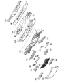
上部ユニット200は、左右対称に構成されているので、以下、左側の構成について説明し、右側の構成についての説明は省略する。図3に示すように、上部ユニット200は、ブラケット130、スペーサ140、光源基板120、スピーカ67、リフレクタ110、ベース部材100、導光棒70、押え部材64、装飾部材63、スポットレンズ65、スポットリフレクタ66、インナーレンズ68、およびアウターレンズ69を備えている。 Since the upper unit 200 is symmetrically configured, the configuration on the left side will be described below, and the configuration on the right side will be omitted. As shown in FIG. 3, the upper unit 200 includes a bracket 130, a spacer 140, a light source substrate 120, a speaker 67, a reflector 110, a base member 100, a light guide rod 70, a holding member 64, a decorative member 63, a spot lens 65, and a spot. It includes a reflector 66, an inner lens 68, and an outer lens 69.

図2に示した照明装置38は、光源基板120、リフレクタ110、ベース部材100、および導光棒70とを備えている。導光棒70は、棒状に形成されており、長手方向における一方の端部の背面側に配置されているLED(光源)121(図11に示す)によって照らされ、発光した状態で正面側から遊技者に視認されるようになっている。これにより、遊技機の装飾性が向上する。
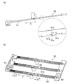
図4は、導光棒70を正面側から見た斜視図である。図5(a)は、導光棒70を正面から見た図である。図5(b)は、図5(a)におけるCC線の断面図である。図6は、導光棒70を背面から見た図である。
以下、図4に示すように、導光棒70が、左右方向に延在する3本の導光棒が連結されて形成されている場合について説明するが、導光棒の数はこれに限定されるものではなく、導光棒70は少なくとも一つの棒状の導光棒を備えていればよい。導光棒70は、前方側(光源側とは反対側)に位置する透光性樹脂部80と、後方側(光源側)に位置する非透光性樹脂部90とが二色成形によって一体に形成されている部材である。
The lighting device 38 shown in FIG. 2 includes a light source substrate 120, a reflector 110, a base member 100, and a light guide rod 70. The light guide rod 70 is formed in a rod shape, is illuminated by an LED (light source) 121 (shown in FIG. 11) arranged on the back side of one end in the longitudinal direction, and emits light from the front side. It is designed to be visually recognized by the player. As a result, the decorativeness of the game machine is improved.
FIG. 4 is a perspective view of the light guide rod 70 as viewed from the front side. FIG. 5A is a front view of the light guide rod 70. FIG. 5B is a cross-sectional view of the CC line in FIG. 5A. FIG. 6 is a view of the light guide rod 70 as viewed from the back.
Hereinafter, as shown in FIG. 4, a case where the light guide rod 70 is formed by connecting three light guide rods extending in the left-right direction will be described, but the number of light guide rods is limited to this. The light guide rod 70 may be provided with at least one rod-shaped light guide rod. In the light guide rod 70, the translucent resin portion 80 located on the front side (opposite to the light source side) and the non-translucent resin portion 90 located on the rear side (light source side) are integrated by two-color molding. It is a member formed in.

図7を用いて透光性樹脂部80について説明する。図7(a)は、透光性樹脂部80を上面から見た図である。図7(b)は、透光性樹脂部80を正面側から見た斜視図である。透光性樹脂部80は、透光性を有する透明部材であり、例えば、ポリカーボネート樹脂等で形成されている。透光性樹脂部80は、上面から見て略L字形状に形成されている。透光性樹脂部80は、導光部81、光導入部82、連結部83および屈曲部84を備えている。導光部81は、左右方向に延在する棒状の部位である。図7(a)に示す導光部81は、左右方向に対して、右側から左側に向かうほど前方側(遊技者側)に位置するように傾斜している。この傾斜は意匠性等を考慮して形成されているものであるが、導光部81は左右方向と平行に形成されていてもよい。光導入部82は、導光部81の長手方向の一端(右端)から光源(LED121)に向かって延在する棒状の部位である。図7(a)に示す光導入部82は、前後方向と略平行となるように形成されている。連結部83は、導光部81の長手方向の一端(左端)に形成され、導光部81の左端同士を互いに連結する板状の部位である。後方側に配置されたLED121から出射された光は、光導入部82で導入され、後述する屈曲部84の傾斜面84aで反射されて導光部81の内部に進行するようになっている。 The translucent resin portion 80 will be described with reference to FIG. 7. FIG. 7A is a view of the translucent resin portion 80 as viewed from above. FIG. 7B is a perspective view of the translucent resin portion 80 as viewed from the front side. The translucent resin portion 80 is a transparent member having translucency, and is formed of, for example, a polycarbonate resin or the like. The translucent resin portion 80 is formed in a substantially L shape when viewed from the upper surface. The translucent resin portion 80 includes a light guide portion 81, a light introduction portion 82, a connecting portion 83, and a bending portion 84. The light guide portion 81 is a rod-shaped portion extending in the left-right direction. The light guide portion 81 shown in FIG. 7A is inclined so as to be located on the front side (player side) from the right side to the left side in the left-right direction. Although this inclination is formed in consideration of designability and the like, the light guide portion 81 may be formed parallel to the left-right direction. The light introduction unit 82 is a rod-shaped portion extending from one end (right end) in the longitudinal direction of the light guide unit 81 toward the light source (LED121). The light introduction portion 82 shown in FIG. 7A is formed so as to be substantially parallel to the front-rear direction. The connecting portion 83 is formed at one end (left end) of the light guide portion 81 in the longitudinal direction, and is a plate-shaped portion that connects the left ends of the light guide portions 81 to each other. The light emitted from the LED 121 arranged on the rear side is introduced by the light introduction unit 82, reflected by the inclined surface 84a of the bending portion 84 described later, and travels inside the light guide unit 81.

導光部81と光導入部82との境界となる位置には、折り曲げ形状である屈曲部84が形成されている。屈曲部84には、前後方向および左右方向のそれぞれに対して傾斜した面である傾斜面84aが形成されている。傾斜面84aは、光導入部82の内部を進行してきた光を、導光部81側に向かって反射するために設けられている。 A bent portion 84 having a bent shape is formed at a position serving as a boundary between the light guide portion 81 and the light introducing portion 82. The bent portion 84 is formed with an inclined surface 84a which is an inclined surface in each of the front-rear direction and the left-right direction. The inclined surface 84a is provided to reflect the light traveling inside the light introduction unit 82 toward the light guide unit 81 side.

光導入部82は、上下方向に対して二股状に分岐されている。光導入部82における後方側の端面は、LED121から出射された光が入射する入射面82a,82bとなっている。このように光導入部82が二股状に形成されているため、一つの光導入部82から二つのLED121の光を導入でき、導光部81の発光輝度をより高くすることができる。なお、光導入部82の分岐数は二つに限定されるものではなく、二つ以上としてもよい。また、一つのLED121で十分な発光輝度が得られる場合には、光導入部82を分岐させなくてもよい。 The light introduction unit 82 is bifurcated in the vertical direction. The rear end faces of the light introduction unit 82 are incident surfaces 82a and 82b on which the light emitted from the LED 121 is incident. Since the light introduction unit 82 is formed in a bifurcated shape in this way, the light of the two LEDs 121 can be introduced from one light introduction unit 82, and the emission brightness of the light guide unit 81 can be further increased. The number of branches of the light introduction unit 82 is not limited to two, and may be two or more. Further, when sufficient emission brightness can be obtained with one LED 121, the light introduction unit 82 does not have to be branched.

次に、図8を用いて非透光性樹脂部90について説明する。図8(a)は、非透光性樹脂部90を上面から見た図である。図8(b)は、非透光性樹脂部90を正面側から見た斜視図である。非透光性樹脂部90は、非透光性の白色部材であり、例えば、ポリカーボネート樹脂等で形成されている。非透光性樹脂部90は、反射部91、フランジ部92、連結部93、およびボス(取付部)94とを備えている。反射部91は、図7(b)で示した導光部81と対向するように導光部81の背面側に形成されて左右方向に延在する棒状(板状)の部位である。フランジ部92は、反射部91の長手方向の一端(右端)に形成されて反射部91の右端同士を互いに連結する板状の部位である。フランジ部92は、二色成形された際に、図7(b)で示した光導入部82における屈曲部84側の端部の外周を取り囲むように形成されている。これにより、光導入部82の上下方向に対する位置が規制されることとなる。連結部93は、反射部91の長手方向の一端(左端)に形成されて反射部91の左端同士を互いに連結する板状の部位である。ボス(取付部)94は、反射部91における左右方向略中央の背面に立設された円柱状の部位である。 Next, the non-transmissive resin portion 90 will be described with reference to FIG. FIG. 8A is a view of the non-transmissive resin portion 90 viewed from above. FIG. 8B is a perspective view of the non-transmissive resin portion 90 as viewed from the front side. The non-transmissive resin portion 90 is a non-transmissive white member, and is made of, for example, a polycarbonate resin or the like. The non-transmissive resin portion 90 includes a reflecting portion 91, a flange portion 92, a connecting portion 93, and a boss (mounting portion) 94. The reflecting portion 91 is a rod-shaped (plate-shaped) portion formed on the back surface side of the light guide portion 81 so as to face the light guide portion 81 shown in FIG. 7B and extending in the left-right direction. The flange portion 92 is a plate-shaped portion formed at one end (right end) of the reflective portion 91 in the longitudinal direction and connecting the right ends of the reflective portions 91 to each other. The flange portion 92 is formed so as to surround the outer periphery of the end portion on the bent portion 84 side of the light introduction portion 82 shown in FIG. 7B when the two-color molding is performed. As a result, the position of the light introduction unit 82 in the vertical direction is restricted. The connecting portion 93 is a plate-shaped portion formed at one end (left end) of the reflecting portion 91 in the longitudinal direction and connecting the left ends of the reflecting portions 91 to each other. The boss (mounting portion) 94 is a columnar portion erected on the back surface of the reflective portion 91 substantially at the center in the left-right direction.

次に、導光部81と反射部91とが接合している面の形状について説明する。図5(b)に示すように、導光部81と反射部91との境界面は、断面鋸歯状となっている。図8(a)に示すように、反射部91における導光部81の接合面には、長手方向Eに沿って凹部91bと凸部91aとが交互に形成されている。凸部91aは前方側に向かって突出した形状であり、凹部91bは後方側に向かって窪んだ形状となっている。凸部91aの右側(光源側)には、長手方向Eに対して、左側(光源側とは反対側)に向かうほど前方側に位置するように傾斜した面である第一傾斜面91cが形成されている。第一傾斜面91cは、導光部81の内部を進行してきた光を前方側に向かって反射する役割を担っている。一方、凸部91aの左側(光源側とは反対側)には、長手方向Eに対して、右側(光源側)に向かうほど前方側に位置するように傾斜した面である第二傾斜面91dが形成されている。図8(a)に示すように、第一傾斜面91cの長手方向Eに対する傾斜角αは、第二傾斜面91dの長手方向Eに対する傾斜角βより小さくなっている。
上記のとおり、反射部91には長手方向Eに沿って凹部91bと凸部91aとが交互に形成されており、図7で示した導光部81の内部を進行する光は反射部91の第一傾斜面91cで反射され、導光部81を介して前方側に放射される。これにより、正面側から見た場合に、導光棒70の導光部81が均一に発光しているように視認できる。
Next, the shape of the surface where the light guide portion 81 and the reflection portion 91 are joined will be described. As shown in FIG. 5B, the interface between the light guide portion 81 and the reflection portion 91 has a serrated cross section. As shown in FIG. 8A, concave portions 91b and convex portions 91a are alternately formed on the joint surface of the light guide portion 81 in the reflection portion 91 along the longitudinal direction E. The convex portion 91a has a shape protruding toward the front side, and the concave portion 91b has a shape recessed toward the rear side. On the right side (light source side) of the convex portion 91a, a first inclined surface 91c is formed which is an inclined surface so as to be located on the front side toward the left side (the side opposite to the light source side) with respect to the longitudinal direction E. Has been done. The first inclined surface 91c plays a role of reflecting the light traveling inside the light guide portion 81 toward the front side. On the other hand, on the left side of the convex portion 91a (the side opposite to the light source side), the second inclined surface 91d is a surface inclined so as to be located on the front side toward the right side (light source side) with respect to the longitudinal direction E. Is formed. As shown in FIG. 8A, the inclination angle α of the first inclined surface 91c with respect to the longitudinal direction E is smaller than the inclination angle β of the second inclined surface 91d with respect to the longitudinal direction E.
As described above, the reflecting portion 91 is formed with concave portions 91b and convex portions 91a alternately along the longitudinal direction E, and the light traveling inside the light guide portion 81 shown in FIG. 7 is the light traveling through the reflecting portion 91. It is reflected by the first inclined surface 91c and radiated forward through the light guide portion 81. As a result, when viewed from the front side, the light guide portion 81 of the light guide rod 70 can be visually recognized as uniformly emitting light.

ここで、図8(b)に示すように、互いに隣接する凸部91a同士の間隔を間隔Pとする。間隔Pは、長手方向中央部に比べて長手方向両端部の方が狭くなるように形成されている。ここでいう長手方向中央部には、長手方向中央部およびその近傍が含まれる。また、長手方向両端部には、長手方向両端部およびその近傍が含まれる。間隔Pは、一方の端部から長手方向中央部に向かうにつれて広くなるように形成されているととともに、長手方向中央部から他方の端部に向かうにつれて狭くなるように形成されている。また、左側(光源とは反対側)の端部における間隔Pは、右側(光源側)の端部における間隔Pに比べて狭くなっている。このため、輝度が上昇しやすい傾向のある長手方向Eの中央近傍において、前方側に向かって放射される光(反射光)の量が抑制されるとともに、輝度が低下しやすい傾向のある長手方向Eの両端において、反射光の量が増大される。これにより、導光部81の中央近傍において発光輝度の上昇が抑制されるとともに、導光部81の両端近傍において発光輝度の低下が抑制され、正面側から見た場合に、導光棒70の導光部81がより均一に発光しているように視認できる。 Here, as shown in FIG. 8B, the distance between the convex portions 91a adjacent to each other is defined as the distance P. The interval P is formed so that both end portions in the longitudinal direction are narrower than the central portion in the longitudinal direction. The central portion in the longitudinal direction referred to here includes the central portion in the longitudinal direction and its vicinity. Further, both ends in the longitudinal direction include both ends in the longitudinal direction and their vicinity. The interval P is formed so as to widen from one end toward the center in the longitudinal direction and narrow from the center in the longitudinal direction toward the other end. Further, the distance P at the end on the left side (opposite to the light source) is narrower than the distance P at the end on the right side (light source side). Therefore, in the vicinity of the center of the longitudinal direction E where the brightness tends to increase, the amount of light (reflected light) radiated toward the front side is suppressed, and the brightness tends to decrease in the longitudinal direction. The amount of reflected light is increased at both ends of E. As a result, the increase in the emission brightness is suppressed in the vicinity of the center of the light guide portion 81, and the decrease in the emission brightness is suppressed in the vicinity of both ends of the light guide portion 81, so that the light guide rod 70 is viewed from the front side. It can be visually recognized that the light guide unit 81 emits light more uniformly.

以下、図6に示すように、最も上方に位置する反射部91を反射部91Aとし、最も下方に位置する反射部91を反射部91Bとし、反射部91Aと反射部91Bとの間に位置する反射部91を反射部91Cとする。また、反射部91Aの背面に立設されているボス94をボス94aとし、反射部91Bの背面に立設されているボス94をボス94bとし、反射部91Cの背面に立設されているボス94をボス94cとする。ボス94a,94b,94cには、ねじ孔94dが形成されている。図5(a)に示すように、ボス94aは、正面から見て円形状の一部の形状(突出領域Aとする)が、導光棒70の外縁(上縁)から上側にはみ出るように形成されている。また、ボス94bは、正面から見て円形状の一部の形状(突出領域Bとする)が、導光棒70の外縁(下縁)から下側にはみ出るように形成されている。 Hereinafter, as shown in FIG. 6, the uppermost reflecting portion 91 is referred to as a reflecting portion 91A, the lowermost reflecting portion 91 is referred to as a reflecting portion 91B, and is located between the reflecting portion 91A and the reflecting portion 91B. The reflective portion 91 is referred to as a reflective portion 91C. Further, the boss 94 standing on the back surface of the reflecting unit 91A is the boss 94a, the boss 94 standing on the back surface of the reflecting unit 91B is the boss 94b, and the boss standing on the back surface of the reflecting unit 91C is. Let 94 be the boss 94c. Screw holes 94d are formed in the bosses 94a, 94b, 94c. As shown in FIG. 5A, the boss 94a has a part of the circular shape (referred to as a protruding region A) when viewed from the front so as to protrude upward from the outer edge (upper edge) of the light guide rod 70. It is formed. Further, the boss 94b is formed so that a part of the circular shape (referred to as a protruding region B) when viewed from the front protrudes downward from the outer edge (lower edge) of the light guide rod 70.

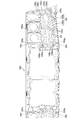
次に、導光棒70の取付相手となるベース部材100について説明する。図9は、ベース部材100を正面から見た図である。図10は、ベース部材100を背面から見た図である。
ベース部材100は、非透光性の赤色部材であり、例えば、ポリカーボネート樹脂等で形成されている。ベース部材100には、正面から見て左下にスピーカグリル101が形成されている。スピーカグリル101は、斜め格子状に形成されており、複数の三角形状の貫通孔を有している。スピーカグリル101は、後述するスピーカ67(図17に示す)から出力される音を、前方(遊技者側)に通音する部位である。
スピーカグリル101における左右方向略中央部であって、導光棒70のボス94a,94b,94cと対向する位置には、円形状の窪み形状である導光棒取付部102a,102b,102cが形成されている。導光棒取付部102aは、スピーカグリル101の上縁の外側となる位置に形成されており、導光棒取付部102bは、スピーカグリル101の下縁の外側となる位置に形成されている。導光棒取付部102cは、スピーカグリル101における上下方向略中央部に形成されている。導光棒取付部102a〜102cは、導光棒70のボス94a〜94cを内部に挿入可能に形成されている。また、図10に示すように、図9で示した導光棒取付部102a〜102cの底面には、前後方向に貫通した取付孔102dが形成されている。
図9に示すように、スピーカグリル101の右側(左右方向内側)であって、導光棒70の光導入部82と対向する位置には、前後方向に貫通した矩形状の貫通孔である導光棒収容孔103が形成されている。導光棒収容孔103は、図7(b)で示した導光棒70の光導入部82を収容可能に形成されており、光導入部82同士の間を仕切るための仕切り板103aが設けられている。
Next, the base member 100 to which the light guide rod 70 is attached will be described. FIG. 9 is a front view of the base member 100. FIG. 10 is a view of the base member 100 as viewed from the back.
The base member 100 is a non-transmissive red member, and is made of, for example, a polycarbonate resin or the like. The speaker grill 101 is formed on the base member 100 at the lower left when viewed from the front. The speaker grill 101 is formed in an oblique lattice pattern, and has a plurality of triangular through holes. The speaker grill 101 is a portion through which the sound output from the speaker 67 (shown in FIG. 17), which will be described later, is passed forward (on the player side).
Light guide rod mounting portions 102a, 102b, 102c having a circular recess shape are formed at positions of the speaker grill 101 substantially in the center in the left-right direction and facing the bosses 94a, 94b, 94c of the light guide rod 70. Has been done. The light guide rod mounting portion 102a is formed at a position outside the upper edge of the speaker grill 101, and the light guide rod mounting portion 102b is formed at a position outside the lower edge of the speaker grill 101. The light guide rod mounting portion 102c is formed at a substantially central portion in the vertical direction of the speaker grill 101. The light guide rod mounting portions 102a to 102c are formed so that the bosses 94a to 94c of the light guide rod 70 can be inserted inside. Further, as shown in FIG. 10, a mounting hole 102d penetrating in the front-rear direction is formed on the bottom surface of the light guide rod mounting portions 102a to 102c shown in FIG.
As shown in FIG. 9, on the right side (inside in the left-right direction) of the speaker grill 101, at a position facing the light introduction portion 82 of the light guide rod 70, a guide having a rectangular through hole penetrating in the front-rear direction. The light rod accommodating hole 103 is formed. The light guide rod accommodating hole 103 is formed so as to accommodate the light introduction portion 82 of the light guide rod 70 shown in FIG. 7 (b), and is provided with a partition plate 103a for partitioning between the light introduction portions 82. Has been done.

導光棒70は、光導入部82が導光棒収容孔103に収容されているとともに、ボス94a〜94cが導光棒取付部102a〜102cの内部に挿入されている状態で、背面側からねじ(不図示)を、取付孔102dを介してボス94a〜94cのねじ孔94dにねじ込むことによって、ベース部材100に固定されている。 The light guide rod 70 is from the back side in a state where the light introduction portion 82 is housed in the light guide rod accommodating hole 103 and the bosses 94a to 94c are inserted inside the light guide rod mounting portions 102a to 102c. A screw (not shown) is fixed to the base member 100 by being screwed into the screw hole 94d of the bosses 94a to 94c via the mounting hole 102d.

図11は、ベース部材100の背面側に配置される、リフレクタ110、光源基板120、ブラケット130、およびスペーサ140を正面側から見た分解斜視図である。
光源基板120は、LED121を含む複数の素子が前面に実装された板状の部品である。LED121は、導光棒70の光導入部82と対向する位置等に配置されている。LED121から出射された光は、光導入部82の入射面82a,82bに入射するようになっている。
FIG. 11 is an exploded perspective view of the reflector 110, the light source substrate 120, the bracket 130, and the spacer 140 arranged on the back side of the base member 100 as viewed from the front side.
The light source substrate 120 is a plate-shaped component in which a plurality of elements including the LED 121 are mounted on the front surface. The LED 121 is arranged at a position facing the light introduction portion 82 of the light guide rod 70 or the like. The light emitted from the LED 121 is incident on the incident surfaces 82a and 82b of the light introduction unit 82.

リフレクタ110は、LED121から出射された光を反射または遮光するために設けられている部材であり、光源基板120の前面側を覆うような形状で形成されている。リフレクタ110には、導光棒70の光導入部82と対向する位置に、前後方向に貫通した矩形状の貫通孔である開口部111が形成されている。これにより、LED121から出射された光は、開口部111を介して、光導入部82の入射面82a,82bに入射するようになっている。また、図10に示すように、ベース部材100の背面には、リフレクタ110を取り付けるための複数のボス104が立設されている。ボス104には、ねじ孔104aが形成されている。図11に示すように、リフレクタ110は、ボス104と対向する位置に設けられた複数の取付孔112を備えている。リフレクタ110は、背面側からねじ(不図示)を、取付孔112を介してボス104のねじ孔104aにねじ込むことによって、ベース部材100に固定されている。 The reflector 110 is a member provided for reflecting or blocking the light emitted from the LED 121, and is formed in a shape that covers the front surface side of the light source substrate 120. The reflector 110 is formed with an opening 111 which is a rectangular through hole penetrating in the front-rear direction at a position facing the light introduction portion 82 of the light guide rod 70. As a result, the light emitted from the LED 121 is incident on the incident surfaces 82a and 82b of the light introduction unit 82 through the opening 111. Further, as shown in FIG. 10, a plurality of bosses 104 for attaching the reflector 110 are erected on the back surface of the base member 100. A screw hole 104a is formed in the boss 104. As shown in FIG. 11, the reflector 110 includes a plurality of mounting holes 112 provided at positions facing the boss 104. The reflector 110 is fixed to the base member 100 by screwing a screw (not shown) from the back surface side into the screw hole 104a of the boss 104 via the mounting hole 112.

図12は、リフレクタ110が取り付けられた状態のベース部材100を背面から見た図である。リフレクタ110の背面側には、複数のボス113が立設されている。ボス113には、ねじ孔113aが形成されている。図11に示すように、光源基板120は、ボス113と対向する位置に設けられた複数の取付孔122、およびU字形状の切り欠きである複数の切欠部123を備えている。また、スペーサ140は、所定のボス113と対向する位置に設けられた複数の取付孔141を備えている。また、ブラケット130は、所定のボス113と対向する位置に設けられた複数の取付孔131を備えている。
光源基板120およびブラケット130は、背面側からねじ(不図示)を取付孔131、取付孔122および切欠部123を介して、図12で示したボス113のねじ孔113aにねじ込むことによって、ベース部材100(リフレクタ110)に固定されている。
光源基板120およびスペーサ140は、背面側からねじ(不図示)を取付孔141および取付孔122を介して、図12で示したボス113のねじ孔113aにねじ込むことによって、ベース部材100(リフレクタ110)に固定されている。
FIG. 12 is a rear view of the base member 100 with the reflector 110 attached. A plurality of bosses 113 are erected on the back side of the reflector 110. A screw hole 113a is formed in the boss 113. As shown in FIG. 11, the light source substrate 120 includes a plurality of mounting holes 122 provided at positions facing the boss 113, and a plurality of notches 123 which are U-shaped notches. Further, the spacer 140 is provided with a plurality of mounting holes 141 provided at positions facing the predetermined boss 113. Further, the bracket 130 includes a plurality of mounting holes 131 provided at positions facing the predetermined boss 113.
The light source substrate 120 and the bracket 130 are base members by screwing screws (not shown) from the back surface side into the screw holes 113a of the boss 113 shown in FIG. 12 through the mounting holes 131, the mounting holes 122, and the notch 123. It is fixed to 100 (reflector 110).
The light source substrate 120 and the spacer 140 are formed by screwing a screw (not shown) from the back surface side into the screw hole 113a of the boss 113 shown in FIG. 12 through the mounting holes 141 and 122 to form the base member 100 (reflector 110). ) Is fixed.

次に、導光棒70の前面側からの取り付けについて説明する。
図5(a)に示すように、導光棒70の連結部93には取付孔74が形成されている。また、導光棒70のフランジ部92には取付孔75が形成されている。
図9に示すように、ベース部材100におけるスピーカグリル101の左右両端であって、取付孔74,75に対向する位置には、ねじ孔104a,104bが形成されている。導光棒70の左側は、前面側からねじ(不図示)を、取付孔74を介してベース部材100のねじ孔104aにねじ込むことによって、ベース部材100に固定されている。一方、導光棒70の右側は、後述する押え部材64によって前方から押えられた状態でねじ締めされて、ベース部材100に固定されている。
Next, attachment of the light guide rod 70 from the front surface side will be described.
As shown in FIG. 5A, a mounting hole 74 is formed in the connecting portion 93 of the light guide rod 70. Further, a mounting hole 75 is formed in the flange portion 92 of the light guide rod 70.
As shown in FIG. 9, screw holes 104a and 104b are formed at both left and right ends of the speaker grill 101 in the base member 100 and at positions facing the mounting holes 74 and 75. The left side of the light guide rod 70 is fixed to the base member 100 by screwing a screw (not shown) from the front surface side into the screw hole 104a of the base member 100 via the mounting hole 74. On the other hand, the right side of the light guide rod 70 is screwed in a state of being pressed from the front by the pressing member 64 described later, and is fixed to the base member 100.

図13を用いて押え部材64について説明する。図13(a)は、押え部材64を正面から見た図である。図13(b)は、押え部材64を図13(a)に示すS方向から見た図である。
押え部材64は、図8(b)で示した導光棒70のフランジ部92に当接するように形成されている。押え部材64は、非透光性の白色部材であり、例えば、ABS樹脂等で形成されている。図13(a)に示すように、押え部材64には、図5(a)で示した導光棒70の取付孔75と連通する取付孔64bが形成されている。また、図13(b)に示すように、押え部材64には、図7(b)で示した導光棒70の屈曲部84を覆うための窪み形状である複数の凹部64aが形成されている。導光棒70の右側は、前面側からねじ(不図示)を、取付孔64bおよび取付孔75を介してベース部材100のねじ孔104bにねじ込むことによって、ベース部材100に固定されている。
The pressing member 64 will be described with reference to FIG. FIG. 13A is a front view of the pressing member 64. FIG. 13B is a view of the pressing member 64 as viewed from the S direction shown in FIG. 13A.
The pressing member 64 is formed so as to come into contact with the flange portion 92 of the light guide rod 70 shown in FIG. 8 (b). The pressing member 64 is a non-transmissive white member, and is made of, for example, ABS resin or the like. As shown in FIG. 13A, the holding member 64 is formed with a mounting hole 64b that communicates with the mounting hole 75 of the light guide rod 70 shown in FIG. 5A. Further, as shown in FIG. 13B, the pressing member 64 is formed with a plurality of recesses 64a having a concave shape for covering the bent portion 84 of the light guide rod 70 shown in FIG. 7B. There is. The right side of the light guide rod 70 is fixed to the base member 100 by screwing a screw (not shown) from the front surface side into the screw hole 104b of the base member 100 via the mounting hole 64b and the mounting hole 75.

次に、図2で示した装飾部材63の取り付けについて説明する。図14(a)は、装飾部材63を正面側から見た斜視図である。図14(b)は、装飾部材63を背面から見た図である。装飾部材63は、前面側からベース部材100に取り付けられる部材であり、正面から見て略L字形状に形成されている。装飾部材63は、非透光性の赤色部材であり、例えば、ポリカーボネート樹脂等で形成されている。装飾部材63は、上下方向に延びる短尺延在部63aと、左右方向に延びる長尺延在部63bとを備えている。装飾部材63は、短尺延在部63aが導光棒70の連結部83(図7(b))および連結部93(図8(b))を覆うとともに、長尺延在部63bが導光棒70の下部側に配置されるようにして、ベース部材100に固定されている。 Next, the attachment of the decorative member 63 shown in FIG. 2 will be described. FIG. 14A is a perspective view of the decorative member 63 as viewed from the front side. FIG. 14B is a view of the decorative member 63 as viewed from the back. The decorative member 63 is a member attached to the base member 100 from the front surface side, and is formed in a substantially L shape when viewed from the front surface. The decorative member 63 is a non-transmissive red member, and is made of, for example, a polycarbonate resin or the like. The decorative member 63 includes a short extending portion 63a extending in the vertical direction and a long extending portion 63b extending in the left-right direction. In the decorative member 63, the short extending portion 63a covers the connecting portion 83 (FIG. 7 (b)) and the connecting portion 93 (FIG. 8 (b)) of the light guide rod 70, and the long extending portion 63b guides the light guide. It is fixed to the base member 100 so as to be arranged on the lower side of the rod 70.

図14(b)に示すように、短尺延在部63aの背面には、ボス63cが立設されている。長尺延在部63bの背面には、ボス63d、爪部63e、および壁部63fが立設されている。ボス63c,63dには、ねじ孔63gが形成されている。図9に示すように、ベース部材100には、装飾部材63のボス63c,63dに対向する位置に、円形状の窪み形状である装飾部材取付部105a,105bが形成されている。また、ベース部材100には、装飾部材63の爪部63eに対向する位置に、爪嵌合部106が形成されている。また、ベース部材100には、装飾部材63の壁部63fに対向する位置に、壁部収容部107が形成されている。また、図10に示すように、図9で示した装飾部材取付部105a,105bの底面には、前後方向に貫通した取付孔105cが形成されている。
装飾部材63は、ボス63c,63dが装飾部材取付部105a,105bに挿入され、かつ壁部64eが壁部収容部107に収容され、かつ爪部63eが爪嵌合部106に嵌合されている状態でベース部材100に仮固定され、背面側からねじ(不図示)を、取付孔105cを介してボス63c,63dのねじ孔63gにねじ込むことによって、ベース部材100に固定されている。装飾部材63がベース部材100に固定されている状態では、図5(a)で示した導光棒70の突出領域Bが装飾部材63によって覆われているため、突出領域Bは正面側(遊技者側)からは視認されないようになっている。
As shown in FIG. 14B, a boss 63c is erected on the back surface of the short extending portion 63a. A boss 63d, a claw portion 63e, and a wall portion 63f are erected on the back surface of the long extending portion 63b. Screw holes 63g are formed in the bosses 63c and 63d. As shown in FIG. 9, the base member 100 is formed with decorative member mounting portions 105a and 105b having a circular recess shape at positions facing the bosses 63c and 63d of the decorative member 63. Further, the base member 100 is formed with a claw fitting portion 106 at a position facing the claw portion 63e of the decorative member 63. Further, the base member 100 is formed with a wall portion accommodating portion 107 at a position facing the wall portion 63f of the decorative member 63. Further, as shown in FIG. 10, mounting holes 105c penetrating in the front-rear direction are formed on the bottom surfaces of the decorative member mounting portions 105a and 105b shown in FIG.
In the decorative member 63, the bosses 63c and 63d are inserted into the decorative member mounting portions 105a and 105b, the wall portion 64e is housed in the wall portion accommodating portion 107, and the claw portion 63e is fitted into the claw fitting portion 106. It is temporarily fixed to the base member 100 in this state, and is fixed to the base member 100 by screwing a screw (not shown) from the back surface side into the screw hole 63g of the bosses 63c and 63d via the mounting hole 105c. In the state where the decorative member 63 is fixed to the base member 100, the protruding region B of the light guide rod 70 shown in FIG. 5A is covered by the decorative member 63, so that the protruding region B is on the front side (game). It is not visible from the person's side).

次に、図2で示した照明装置33について説明する。照明装置33は、図3で示した光源基板120、リフレクタ110、ベース部材100、スポットレンズ65、およびスポットリフレクタ66を備えている。
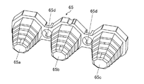
図15は、スポットレンズ65を正面側から見た斜視図である。スポットレンズ65は、光源基板120に実装された複数のLED121に照らされて発光した状態で、正面側から遊技者に視認される部材である。スポットレンズ65は、透光性を有する透明部材であり、例えば、ポリカーボネート等の樹脂で形成されている。スポットレンズ65は、正面から見て正八角形状であって、前方に向かって先細となるように形成されたレンズ65a,65b,65cを、左右方向に連結させて形成されている。レンズ65aとレンズ65bとの連結部、およびレンズ65bとレンズ65cとの連結部には、前後方向に貫通した取付孔65dが形成されている。
Next, the lighting device 33 shown in FIG. 2 will be described. The lighting device 33 includes a light source substrate 120, a reflector 110, a base member 100, a spot lens 65, and a spot reflector 66 shown in FIG.
FIG. 15 is a perspective view of the spot lens 65 as viewed from the front side. The spot lens 65 is a member that is visually recognized by the player from the front side in a state of being illuminated by a plurality of LEDs 121 mounted on the light source substrate 120 and emitting light. The spot lens 65 is a transparent member having translucency, and is made of, for example, a resin such as polycarbonate. The spot lens 65 has a regular octagonal shape when viewed from the front, and is formed by connecting lenses 65a, 65b, 65c formed so as to taper toward the front in the left-right direction. A mounting hole 65d penetrating in the front-rear direction is formed in the connecting portion between the lens 65a and the lens 65b and the connecting portion between the lens 65b and the lens 65c.

図16(a)は、スポットリフレクタ66を正面から見た斜視図である。図16(b)は、スポットリフレクタ66を背面から見た図である。スポットリフレクタ66は、スポットレンズ65の周囲を取り囲む枠状の部材であり、スポットレンズ65を内側に収容可能に形成されている。スポットリフレクタ66は、例えば、ABS等の樹脂で形成されており、蒸着によって表面に銀色の薄膜が施されている。これにより、スポットリフレクタ66は非透光性となっている。スポットリフレクタ66は、装飾部材としての役割、図15で示したレンズ65a,65b,65cの間を遮光する役割、およびスポットレンズ65をベース部材100に取り付ける取付部材としての役割を担っている。図16(b)に示すように、スポットリフレクタ66の背面には複数のボス66aが立設されている。ボス66aには、ねじ孔66bが形成されている。 FIG. 16A is a perspective view of the spot reflector 66 as viewed from the front. FIG. 16B is a rear view of the spot reflector 66. The spot reflector 66 is a frame-shaped member that surrounds the periphery of the spot lens 65, and is formed so that the spot lens 65 can be accommodated inside. The spot reflector 66 is made of, for example, a resin such as ABS, and a silver thin film is applied to the surface by vapor deposition. As a result, the spot reflector 66 is non-translucent. The spot reflector 66 plays a role as a decorative member, a role of blocking light between the lenses 65a, 65b, and 65c shown in FIG. 15, and a role of a mounting member for attaching the spot lens 65 to the base member 100. As shown in FIG. 16B, a plurality of bosses 66a are erected on the back surface of the spot reflector 66. A screw hole 66b is formed in the boss 66a.

図9に示すように、ベース部材100には、スポットリフレクタ66のボス66aに対向する位置に、円形状の窪み形状であるスポットリフレクタ取付部108が形成されている。また、図10に示すように、図9で示したスポットリフレクタ取付部108の底面には、前後方向に貫通した取付孔108aが形成されている。
スポットリフレクタ66は、ボス66aが図15で示したスポットレンズ65の取付孔65dに挿通され、かつスポットリフレクタ取付部108に挿入された状態で、背面側からねじ(不図示)を、取付孔108aを介してボス66aのねじ孔66bにねじ込むことによって、ベース部材100に固定されている。スポットリフレクタ66がベース部材100に固定されている状態では、図5(a)で示した導光棒70の突出領域Aがスポットリフレクタ66によって覆われているため、突出領域Aは正面側(遊技者側)からは視認されないようになっている。
As shown in FIG. 9, the base member 100 is formed with a spot reflector mounting portion 108 having a circular recess shape at a position facing the boss 66a of the spot reflector 66. Further, as shown in FIG. 10, a mounting hole 108a penetrating in the front-rear direction is formed on the bottom surface of the spot reflector mounting portion 108 shown in FIG.
The spot reflector 66 has a screw (not shown) inserted from the back side in a state where the boss 66a is inserted into the mounting hole 65d of the spot lens 65 shown in FIG. 15 and inserted into the spot reflector mounting portion 108, and the mounting hole 108a is inserted. It is fixed to the base member 100 by being screwed into the screw hole 66b of the boss 66a via. In the state where the spot reflector 66 is fixed to the base member 100, the protruding region A of the light guide rod 70 shown in FIG. 5A is covered by the spot reflector 66, so that the protruding region A is on the front side (game). It is not visible from the person's side).

図5(a)で示した導光棒70のボス94a,94b,94cは、非透光性であって不透明である反射部91の背面に立設されている。このため、正面側(遊技者側)からのボス94a,94b,94cおよびそれらに挿入されるねじ(不図示)の視認は困難となり、遊技機の意匠性が低下するのを防止できる。また、上述のとおり、導光棒70の突出領域Aおよび突出領域Bは、正面側から意匠部材(スポットリフレクタ66および装飾部材63)によって覆われている。このため、図2に示すように、正面側(遊技者側)からは、突出領域Aおよび突出領域Bを視認することはできない。これにより、遊技機の意匠性が低下するのを防止できる。 The bosses 94a, 94b, 94c of the light guide rod 70 shown in FIG. 5A are erected on the back surface of the reflective portion 91 which is non-translucent and opaque. Therefore, it becomes difficult to visually recognize the bosses 94a, 94b, 94c and the screws (not shown) inserted into them from the front side (player side), and it is possible to prevent the design of the game machine from being deteriorated. Further, as described above, the projecting area A and the projecting area B of the light guide rod 70 are covered with the design members (spot reflector 66 and the decorative member 63) from the front side. Therefore, as shown in FIG. 2, the protruding area A and the protruding area B cannot be visually recognized from the front side (player side). As a result, it is possible to prevent the design of the game machine from being deteriorated.

次に、ベース部材100の背面側に取り付けられるスピーカ67について説明する。図10に示すように、ベース部材100におけるスピーカグリル101が形成されている箇所の背面には、背面から見て長円環状の囲繞壁部109が立設されている。囲繞壁部109は、長手方向壁部109aと短手方向壁部109bとを備えている。長手方向壁部109aは、左右方向に延在しており、略直線状に形成されている。短手方向壁部109bは、上下方向に延在しており、円弧状に形成されている。囲繞壁部109の外側であって、短手方向壁部109bの上下方向両側となる位置には、ボス109cが立設されている。ボス109cには、ねじ孔109dが形成されている。 Next, the speaker 67 attached to the back surface side of the base member 100 will be described. As shown in FIG. 10, an oval ring-shaped surrounding wall portion 109 is erected on the back surface of the base member 100 where the speaker grill 101 is formed. The surrounding wall portion 109 includes a longitudinal wall portion 109a and a lateral wall portion 109b. The longitudinal wall portion 109a extends in the left-right direction and is formed in a substantially linear shape. The lateral wall portion 109b extends in the vertical direction and is formed in an arc shape. Bosses 109c are erected on the outside of the surrounding wall portion 109 and at positions on both sides of the lateral wall portion 109b in the vertical direction. A screw hole 109d is formed in the boss 109c.

図17は、スピーカ67を正面側から見た斜視図である。スピーカ67は、外形が略矩形状であり、スピーカ本体67aとフランジ部67bとを備えている。スピーカ本体67aとフランジ部67bとは、金属により一体に形成されている。スピーカ本体67aは、内部にコーンを備えているとともに、後端部にボイスコイル等が設けられている。フランジ部67bは、スピーカ67の先端面67cからスピーカ67の後端側に向かって所定の距離だけ離間した位置において、スピーカ本体67aの外側に向けて張り出すようにして形成されている。また、フランジ部67bは、正面から見て外形が略矩形状であり、四隅には取付孔67dが形成されている。スピーカ67の先端面67cは、正面から見て長円環状に形成されており、先端面67cがベース部材100の囲繞壁部109の先端面に当接するようになっている。 FIG. 17 is a perspective view of the speaker 67 as viewed from the front side. The speaker 67 has a substantially rectangular outer shape, and includes a speaker main body 67a and a flange portion 67b. The speaker body 67a and the flange portion 67b are integrally formed of metal. The speaker main body 67a is provided with a cone inside, and a voice coil or the like is provided at the rear end portion. The flange portion 67b is formed so as to project toward the outside of the speaker main body 67a at a position separated from the front end surface 67c of the speaker 67 toward the rear end side of the speaker 67 by a predetermined distance. Further, the flange portion 67b has a substantially rectangular outer shape when viewed from the front, and mounting holes 67d are formed at the four corners. The tip surface 67c of the speaker 67 is formed in an oval ring shape when viewed from the front, and the tip surface 67c comes into contact with the tip surface of the surrounding wall portion 109 of the base member 100.

スピーカ67は、先端面67cがベース部材100の囲繞壁部109の先端面に当接されているとともに、フランジ部67bのフランジ面がベース部材100のボス109cの先端面に当接されている状態で、背面側からねじ(不図示)を、取付孔67dを介してベース部材100におけるボス109cのねじ孔109dにねじ込むことによって、ベース部材100に固定されている。 In the speaker 67, the tip surface 67c is in contact with the tip surface of the surrounding wall portion 109 of the base member 100, and the flange surface of the flange portion 67b is in contact with the tip surface of the boss 109c of the base member 100. Then, a screw (not shown) is screwed into the screw hole 109d of the boss 109c in the base member 100 via the mounting hole 67d from the back surface side to be fixed to the base member 100.

既述のとおり、スピーカグリル101の前面側には導光棒70が取り付けられているが、導光棒70は撓みの最も大きくなる左右方向中央をねじ締めされて固定されている。これにより、スピーカ67から音が出力された際における導光棒70の振動(ビビリ)が抑制されている。 As described above, the light guide rod 70 is attached to the front side of the speaker grill 101, but the light guide rod 70 is fixed by screwing the center in the left-right direction where the deflection is maximum. As a result, the vibration (chatter) of the light guide rod 70 when the sound is output from the speaker 67 is suppressed.

また、導光棒70は、光導入部82を介して光を導入し、導光部81が発光するように形成されている。このため、スピーカ67とスピーカグリル101との間に導光部81を発光させるための光源基板を設ける必要がない。これにより、スピーカ67の開口率が低下し、スピーカ67から出力される音の音質が低下するのを防止できる。ここで、スピーカ67の開口率とは、正面から見た際におけるスピーカ67の開口S(図17)の面積を分母とし、開口Sがその他の部材によって塞がれていない領域の面積を分子として求められる割合である。また、図9で示したように、導光棒取付部102aが、スピーカグリル101の上縁の外側に形成されているとともに、導光棒取付部102bが、スピーカグリル101の下縁の外側に形成されているため、スピーカグリル101の開口率が低下するのをさらに防止できる。 Further, the light guide rod 70 is formed so that light is introduced through the light introduction unit 82 and the light guide unit 81 emits light. Therefore, it is not necessary to provide a light source substrate for causing the light guide portion 81 to emit light between the speaker 67 and the speaker grill 101. As a result, it is possible to prevent the aperture ratio of the speaker 67 from being lowered and the sound quality of the sound output from the speaker 67 from being lowered. Here, the aperture ratio of the speaker 67 is defined by the area of the opening S (FIG. 17) of the speaker 67 when viewed from the front as the denominator and the area of the region where the opening S is not blocked by other members as the numerator. This is the required ratio. Further, as shown in FIG. 9, the light guide rod mounting portion 102a is formed on the outside of the upper edge of the speaker grill 101, and the light guide rod mounting portion 102b is formed on the outside of the lower edge of the speaker grill 101. Since it is formed, it is possible to further prevent the opening ratio of the speaker grill 101 from decreasing.

図18は、リフレクタ110によって覆われている状態の光源基板120を正面から見た図である。
図18に示すように、複数のLED121のそれぞれの近傍には、各LED121を識別するための識別符号124が記されている。光源基板120の前面にはn個(nは1以上の整数)のLED121が実装されているが、各LED121には、1〜nまでの通し番号が付与されている。識別符号124は、光源基板120の前面(LED121実装面)における各LED121の近傍となる位置に、通し番号に対応させて記されている「LED1」〜「LEDn」までの文字である。なお、ここでいう文字には、数字や記号等が含まれる。図18は、識別符号124として「LED1」〜「LED9」が記された例を示している。通し番号は、遊技機(光源基板120)の設計者によって定められている。例えば、n個のLED121のうちの1個のLED121が点灯しなくなった場合等に、当該点灯しなくなったLED121の識別符号124を確認することで、点灯しなくなったLED121の通し番号を判別することが可能となる。これにより、当該点灯しなくなったLED121の識別符号124から光源基板120の回路図等を辿ることで、光源基板120の故障個所等を解析することが可能となる。
FIG. 18 is a front view of the light source substrate 120 in a state of being covered with the reflector 110.
As shown in FIG. 18, an identification code 124 for identifying each LED 121 is written in the vicinity of each of the plurality of LEDs 121. N (n is an integer of 1 or more) LEDs 121 are mounted on the front surface of the light source substrate 120, and each LED 121 is given a serial number from 1 to n. The identification code 124 is a character from "LED1" to "LEDn" that is written corresponding to a serial number at a position near each LED 121 on the front surface of the light source substrate 120 (LED121 mounting surface). The characters referred to here include numbers, symbols, and the like. FIG. 18 shows an example in which "LED1" to "LED9" are marked as the identification code 124. The serial number is determined by the designer of the game machine (light source substrate 120). For example, when one of the n LEDs 121 does not light up, the serial number of the LED 121 that does not light up can be determined by checking the identification code 124 of the LED 121 that does not light up. It will be possible. As a result, it is possible to analyze the faulty part of the light source board 120 by tracing the circuit diagram of the light source board 120 from the identification code 124 of the LED 121 that is no longer lit.

また、識別符号124は、リフレクタ110が光源基板120の前面側に配置された状態でも、各LED121を識別可能な位置に設けられている。既述のとおり、光源基板120はリフレクタ110によって前面側を覆われているが、リフレクタ110には開口部111等の開口が形成されているため、LED121は開口部111等を介して露出した状態となる。そして、開口部111等を介してLED121が露出した状態では、正面視から識別符号124を視認することができるようになっている。このため、各LED121の通し番号が何番なのかを把握することができる。このとき、識別符号124は、その全体が視認可能となっていなくてもよく、各LED121を識別可能な状態となっていればよい。例えば、図18における「LED1」、「LED3」、「LED5」、「LED6」等の識別符号124は、その一部(文字部分)がリフレクタ110によって隠されているが、識別符号124における数字部分が見えているため、各LED121を識別することが可能となっている。
なお、図示は省略するが、識別符号124としての「LED1」〜「LEDn」の文字のうちの数字部分「1」〜「n」は、リフレクタ110が光源基板120の前面側に配置された状態において、正面側からすべて視認可能な状態となっている。したがって、リフレクタ110が光源基板120の前面側に配置された状態において、光源基板120の前面側に設けられたLED121はすべて、識別符号124により識別可能な状態となっている。
Further, the identification code 124 is provided at a position where each LED 121 can be identified even when the reflector 110 is arranged on the front side of the light source substrate 120. As described above, the light source substrate 120 is covered on the front surface side by the reflector 110, but since the reflector 110 is formed with an opening such as an opening 111, the LED 121 is exposed through the opening 111 or the like. It becomes. Then, in a state where the LED 121 is exposed through the opening 111 or the like, the identification code 124 can be visually recognized from the front view. Therefore, it is possible to know what the serial number of each LED 121 is. At this time, the identification code 124 does not have to be visible as a whole, and each LED 121 may be in a state where it can be identified. For example, the identification code 124 of "LED1", "LED3", "LED5", "LED6", etc. in FIG. 18 has a part (character part) hidden by the reflector 110, but the number part in the identification code 124. Is visible, so that each LED 121 can be identified.
Although not shown, the number portions "1" to "n" of the characters "LED1" to "LEDn" as the identification code 124 are in a state where the reflector 110 is arranged on the front side of the light source substrate 120. In, everything is visible from the front side. Therefore, in the state where the reflector 110 is arranged on the front side of the light source substrate 120, all the LEDs 121 provided on the front side of the light source substrate 120 are in a state of being identifiable by the identification code 124.

また、光源基板120の前面に設けられた識別符号124はすべて、LED121に対して同じ側(図18ではLED121の下側)に設けられている。また、識別符号124はすべて、標記方向が揃えられている。例えば図18に示すように、識別符号124はすべて、左から右に読むよう記載されている。 Further, all the identification codes 124 provided on the front surface of the light source substrate 120 are provided on the same side as the LED 121 (lower side of the LED 121 in FIG. 18). Further, all the identification codes 124 have the same marking direction. For example, as shown in FIG. 18, all identification codes 124 are described to be read from left to right.

また、光源基板120やリフレクタ110は、例えば、回転リールのバックライト(回転リールを後側から照明するライト)に用いられるもの等であってもよい。 Further, the light source substrate 120 and the reflector 110 may be, for example, those used for the backlight of the rotating reel (the light that illuminates the rotating reel from the rear side).

光源基板120に対してリフレクタ110が設けられた状態、特に光源基板120とリフレクタ110とが互いに固定された状態において、識別符号124によって光源基板120に実装されたLED121を識別可能な状態となっていれば、光源基板120からリフレクタ110を取り外すことなく、識別符号124によって各LED121を識別できる。これにより、光源基板120の故障時の解析等を容易に行うことができる。 In a state where the reflector 110 is provided on the light source substrate 120, particularly when the light source substrate 120 and the reflector 110 are fixed to each other, the LED 121 mounted on the light source substrate 120 can be identified by the identification code 124. Therefore, each LED 121 can be identified by the identification code 124 without removing the reflector 110 from the light source substrate 120. As a result, it is possible to easily perform analysis at the time of failure of the light source substrate 120.

以上のように、本実施の形態によれば、導光棒70の反射部91における導光部81との接合面には、長手方向に沿って凹部91bと凸部91aとが交互に形成されている。このため、導光部81の内部を進行する光が、凹部91bと凸部91aとが交互に形成されている非透光性の反射部91で反射されて前方側に放射される。したがって、導光棒70を均一に発光させることができる。 As described above, according to the present embodiment, concave portions 91b and convex portions 91a are alternately formed along the longitudinal direction on the joint surface of the light guide rod 70 with the light guide portion 81 in the reflection portion 91. ing. Therefore, the light traveling inside the light guide portion 81 is reflected by the non-transmissive reflecting portion 91 in which the concave portions 91b and the convex portions 91a are alternately formed, and is radiated to the front side. Therefore, the light guide rod 70 can be made to emit light uniformly.

また、反射部91の隣り合う凸部91aの間隔は、長手方向中央部に比べて長手方向両端部の方が狭くなっている。このため、長手方向中央部において反射部91で反射されて前方側に放射される反射光の量が抑制されるとともに、長手方向両端部において前方側に放射される反射光の量が増大されるので、導光部81の中央近傍において輝度の上昇が抑制されるとともに、導光部81の両端において輝度の低下が抑制される。したがって、導光棒70をより均一に発光させることができる。 Further, the distance between the adjacent convex portions 91a of the reflecting portions 91 is narrower at both end portions in the longitudinal direction than at the central portion in the longitudinal direction. Therefore, the amount of reflected light reflected by the reflecting portion 91 at the central portion in the longitudinal direction and emitted to the front side is suppressed, and the amount of reflected light emitted to the front side at both ends in the longitudinal direction is increased. Therefore, the increase in brightness is suppressed near the center of the light guide unit 81, and the decrease in brightness is suppressed at both ends of the light guide unit 81. Therefore, the light guide rod 70 can emit light more uniformly.

また、導光棒70は、長手方向における一方の端部からLED121に向かって延在するように形成された光導入部82をさらに備え、光導入部82は、複数のLED121に向かって複数に分岐するように形成されている。このため、導光棒70は、複数に分岐されている光導入部82を介して、複数のLED121から出射される光を取り入れることができる。したがって、導光棒70の発光輝度を上昇させることができる。 Further, the light guide rod 70 further includes a light introduction unit 82 formed so as to extend from one end in the longitudinal direction toward the LED 121, and the light introduction units 82 are plurality of toward the plurality of LEDs 121. It is formed to branch. Therefore, the light guide rod 70 can take in the light emitted from the plurality of LEDs 121 via the light introduction unit 82 branched into a plurality of branches. Therefore, the emission brightness of the light guide rod 70 can be increased.

また、導光棒70のボス94が、非透光性であって不透明である反射部91の背面側に立設されているため、正面側からのボス94の視認が困難となる。したがって、遊技機の意匠性が低下するのを防止できる。 Further, since the boss 94 of the light guide rod 70 is erected on the back side of the reflecting portion 91 which is non-translucent and opaque, it becomes difficult to visually recognize the boss 94 from the front side. Therefore, it is possible to prevent the design of the game machine from being deteriorated.

また、ボス94は、正面側から見て円形状の一部の形状が導光棒70の外縁から外側にはみ出るように形成されているが、当該一部の形状は正面側から意匠部材(装飾部材63,スポットリフレクタ66)によって覆われるように形成されている。このため、当該一部の形状が正面側から視認されることはない。したがって、遊技機の意匠性が低下するのを防止できる。また、ボス部94が挿入される相手形状が、スピーカグリル101の外縁の外側に形成されているため、スピーカ67の開口率の低下が抑制される。したがって、スピーカ67から出力される音の音質が低下するのを防止できる。 Further, the boss 94 is formed so that a part of the circular shape when viewed from the front side protrudes from the outer edge of the light guide rod 70 to the outside, but the part of the shape is a design member (decoration) from the front side. It is formed so as to be covered by the member 63 and the spot reflector 66). Therefore, the part of the shape is not visible from the front side. Therefore, it is possible to prevent the design of the game machine from being deteriorated. Further, since the mating shape into which the boss portion 94 is inserted is formed on the outside of the outer edge of the speaker grill 101, a decrease in the aperture ratio of the speaker 67 is suppressed. Therefore, it is possible to prevent the sound quality of the sound output from the speaker 67 from deteriorating.

また、ストップボタン54を動作させるために必要な力は、MAXベットボタン56を動作させるために必要な力よりも小さく設定されている。このため、遊技者は、ストップボタンの操作に関して軽くて心地よい操作フィーリングを得ることができるとともに、テンポよくすべてのストップボタンを押下することが可能となる。したがって、遊技者は快適に遊技を行うことが可能となり、遊技性が向上する。 Further, the force required to operate the stop button 54 is set to be smaller than the force required to operate the MAX bet button 56. Therefore, the player can obtain a light and comfortable operation feeling regarding the operation of the stop button, and can press all the stop buttons at a good tempo. Therefore, the player can comfortably play the game, and the playability is improved.

なお、本実施の形態では、導光棒70が光導入部82を備えている場合について説明したが、導光棒70は光導入部82を必ずしも備えている必要はない。導光棒70において、導光部81の長手方向における一方の端部に背面側から光が入射されるものであればよい。また、ボス94の形状が円柱状である場合について説明したが、ボス94の形状はこれに限定されるものではなく、例えば方形状であってもよい。 In the present embodiment, the case where the light guide rod 70 includes the light introduction unit 82 has been described, but the light guide rod 70 does not necessarily have to include the light introduction unit 82. In the light guide rod 70, light may be incident on one end of the light guide portion 81 in the longitudinal direction from the back surface side. Further, although the case where the shape of the boss 94 is cylindrical has been described, the shape of the boss 94 is not limited to this, and may be, for example, a square shape.

54 ストップボタン
56 MAXベットボタン(ベットボタン)
63 装飾部材(意匠部材)
66 スポットリフレクタ(意匠部材)
70 導光棒
81 導光部
82 光導入部
91 反射部
94 ボス(取付部)
121 LED(光源)
54 Stop button 56 MAX bet button (bet button)
63 Decorative member (design member)
66 Spot reflector (design member)
70 Light guide rod 81 Light guide part 82 Light introduction part 91 Reflection part 94 Boss (mounting part)
121 LED (light source)

Claims (1)

外周面に複数種類の図柄が配列されたリールと、前記リールを内側から照らすバックライトと、を備える遊技機であって、A gaming machine including a reel in which a plurality of types of symbols are arranged on an outer peripheral surface and a backlight that illuminates the reel from the inside.
前記バックライトは、The backlight is
光源が複数実装された光源基板と、A light source board on which multiple light sources are mounted and
前記光源を露出させる開口を複数有し、前記光源基板の前記光源が実装された面の少なくとも一部を覆うように配置される、光を反射する仕切り部材と、を備え、It comprises a plurality of openings for exposing the light source, and a partition member for reflecting light, which is arranged so as to cover at least a part of the surface on which the light source is mounted on the light source substrate.
前記光源基板には、前記光源それぞれを識別可能とする数字を含む識別符号が設けられており、The light source substrate is provided with an identification code including a number that enables each of the light sources to be identified.
前記識別符号は、前記仕切り部材が配置された状態においても前記開口を介して各識別符号の前記数字の全体が見えるようになっていることを特徴とする遊技機。The identification code is a gaming machine in which the entire number of each identification code can be seen through the opening even when the partition member is arranged.
JP2018026972A 2018-02-19 2018-02-19 Game machine Active JP6780863B2 (en)

Priority Applications (1)

Application Number Priority Date Filing Date Title
JP2018026972A JP6780863B2 (en) 2018-02-19 2018-02-19 Game machine

Applications Claiming Priority (1)

Application Number Priority Date Filing Date Title
JP2018026972A JP6780863B2 (en) 2018-02-19 2018-02-19 Game machine

Publications (3)

Publication Number Publication Date
JP2019141233A JP2019141233A (en) 2019-08-29
JP2019141233A5 JP2019141233A5 (en) 2020-01-16
JP6780863B2 true JP6780863B2 (en) 2020-11-04

Family

ID=67773433

Family Applications (1)

Application Number Title Priority Date Filing Date
JP2018026972A Active JP6780863B2 (en) 2018-02-19 2018-02-19 Game machine

Country Status (1)

Country Link
JP (1) JP6780863B2 (en)

Cited By (1)

* Cited by examiner, † Cited by third party
Publication number Priority date Publication date Assignee Title
JP2021151559A (en) * 2019-06-19 2021-09-30 株式会社オリンピア Game machine

Family Cites Families (18)

* Cited by examiner, † Cited by third party
Publication number Priority date Publication date Assignee Title
JPH1176564A (en) * 1997-09-02 1999-03-23 Sophia Co Ltd Game machine
JP2000167203A (en) * 1998-12-08 2000-06-20 Fuji Shoji:Kk Printed circuit board for game machine
JP3976974B2 (en) * 1999-12-22 2007-09-19 株式会社ニューギン Control board for gaming machines
JP2006141683A (en) * 2004-11-19 2006-06-08 Heiwa Corp Board for displaying
JP5181241B2 (en) * 2008-07-04 2013-04-10 株式会社大都技研 Amusement stand
JP2010119574A (en) * 2008-11-19 2010-06-03 Daito Giken:Kk Board of game machine, game machine, and method of manufacturing board of game machine
JP2010219208A (en) * 2009-03-16 2010-09-30 Murata Machinery Ltd Led array
JP5821352B2 (en) * 2011-07-13 2015-11-24 株式会社三洋物産 Game machine
WO2014030313A1 (en) * 2012-08-23 2014-02-27 パナソニック株式会社 Light-emitting device, light source for lighting use, and lighting device
JP5629878B1 (en) * 2013-12-27 2014-11-26 株式会社大都技研 Amusement stand
JP6688005B2 (en) * 2015-03-24 2020-04-28 株式会社三共 Amusement machine
JP6109226B2 (en) * 2015-04-02 2017-04-05 山佐株式会社 Game machine
JP6312035B2 (en) * 2016-01-18 2018-04-18 株式会社大都技研 Amusement stand
JP6281108B2 (en) * 2016-06-07 2018-02-21 株式会社大都技研 Amusement stand
JP6629677B2 (en) * 2016-06-15 2020-01-15 株式会社ニューギン Gaming machine
JP6440215B2 (en) * 2017-02-15 2018-12-19 株式会社ソフイア Game machine
JP6378394B2 (en) * 2017-04-26 2018-08-22 株式会社藤商事 Game machine
JP6634652B2 (en) * 2018-02-19 2020-01-22 株式会社オリンピア Gaming machine

Cited By (2)

* Cited by examiner, † Cited by third party
Publication number Priority date Publication date Assignee Title
JP2021151559A (en) * 2019-06-19 2021-09-30 株式会社オリンピア Game machine
JP7060283B2 (en) 2019-06-19 2022-04-26 株式会社オリンピア Pachinko machine

Also Published As

Publication number Publication date
JP2019141233A (en) 2019-08-29

Similar Documents

Publication Publication Date Title
JP7066152B2 (en) Pachinko machine
JP6634652B2 (en) Gaming machine
JP4162244B2 (en) Game machine
JP4792318B2 (en) Pachislot and gaming machine islands
JP5388813B2 (en) Game machine
JP7046440B2 (en) Pachinko machine
JP6888828B2 (en) Pachinko machine
JP4822752B2 (en) Pachinko machine
JP6628337B2 (en) Gaming machine
JP6109226B2 (en) Game machine
JP6780863B2 (en) Game machine
JP5519186B2 (en) Game machine
JP5686833B2 (en) Game machine
JP5346169B2 (en) Game machine
JP3890033B2 (en) Game machine
JP6655115B2 (en) Gaming machine
JP5242989B2 (en) Game machine
JP6547145B2 (en) Gaming machine
JP6948056B2 (en) Pachinko machine
JP6762059B2 (en) Game machine
JP5686832B2 (en) Game machine
JP7076745B2 (en) Pachinko machine
JP6002266B2 (en) Game machine
JP6552443B2 (en) Game machine
JP6092949B2 (en) Game machine

Legal Events

Date Code Title Description
A521 Request for written amendment filed

Free format text: JAPANESE INTERMEDIATE CODE: A523

Effective date: 20191129

A621 Written request for application examination

Free format text: JAPANESE INTERMEDIATE CODE: A621

Effective date: 20191129

A871 Explanation of circumstances concerning accelerated examination

Free format text: JAPANESE INTERMEDIATE CODE: A871

Effective date: 20191129

A975 Report on accelerated examination

Free format text: JAPANESE INTERMEDIATE CODE: A971005

Effective date: 20200311

A977 Report on retrieval

Free format text: JAPANESE INTERMEDIATE CODE: A971007

Effective date: 20200318

A131 Notification of reasons for refusal

Free format text: JAPANESE INTERMEDIATE CODE: A132

Effective date: 20200324

A131 Notification of reasons for refusal

Free format text: JAPANESE INTERMEDIATE CODE: A131

Effective date: 20200707

TRDD Decision of grant or rejection written
A01 Written decision to grant a patent or to grant a registration (utility model)

Free format text: JAPANESE INTERMEDIATE CODE: A01

Effective date: 20201006

A61 First payment of annual fees (during grant procedure)

Free format text: JAPANESE INTERMEDIATE CODE: A61

Effective date: 20201008

R150 Certificate of patent or registration of utility model

Ref document number: 6780863

Country of ref document: JP

Free format text: JAPANESE INTERMEDIATE CODE: R150

R250 Receipt of annual fees

Free format text: JAPANESE INTERMEDIATE CODE: R250