JP6779713B2 - In-vehicle antenna device - Google Patents
In-vehicle antenna device Download PDFInfo
- Publication number
- JP6779713B2 JP6779713B2 JP2016170394A JP2016170394A JP6779713B2 JP 6779713 B2 JP6779713 B2 JP 6779713B2 JP 2016170394 A JP2016170394 A JP 2016170394A JP 2016170394 A JP2016170394 A JP 2016170394A JP 6779713 B2 JP6779713 B2 JP 6779713B2
- Authority
- JP
- Japan
- Prior art keywords
- light
- antenna
- vehicle
- opening
- case
- Prior art date
- Legal status (The legal status is an assumption and is not a legal conclusion. Google has not performed a legal analysis and makes no representation as to the accuracy of the status listed.)
- Active
Links
Images


Classifications
-
- B—PERFORMING OPERATIONS; TRANSPORTING
- B60—VEHICLES IN GENERAL
- B60R—VEHICLES, VEHICLE FITTINGS, OR VEHICLE PARTS, NOT OTHERWISE PROVIDED FOR
- B60R11/00—Arrangements for holding or mounting articles, not otherwise provided for
- B60R11/02—Arrangements for holding or mounting articles, not otherwise provided for for radio sets, television sets, telephones, or the like; Arrangement of controls thereof
-
- H—ELECTRICITY
- H01—ELECTRIC ELEMENTS
- H01Q—ANTENNAS, i.e. RADIO AERIALS
- H01Q1/00—Details of, or arrangements associated with, antennas
- H01Q1/06—Means for the lighting or illuminating of antennas, e.g. for purpose of warning
-
- H—ELECTRICITY
- H01—ELECTRIC ELEMENTS
- H01Q—ANTENNAS, i.e. RADIO AERIALS
- H01Q1/00—Details of, or arrangements associated with, antennas
- H01Q1/27—Adaptation for use in or on movable bodies
- H01Q1/32—Adaptation for use in or on road or rail vehicles
-
- H—ELECTRICITY
- H01—ELECTRIC ELEMENTS
- H01Q—ANTENNAS, i.e. RADIO AERIALS
- H01Q1/00—Details of, or arrangements associated with, antennas
- H01Q1/42—Housings not intimately mechanically associated with radiating elements, e.g. radome
Landscapes
- Engineering & Computer Science (AREA)
- Mechanical Engineering (AREA)
- Fittings On The Vehicle Exterior For Carrying Loads, And Devices For Holding Or Mounting Articles (AREA)
- Details Of Aerials (AREA)
Description
本発明は、車載アンテナ装置に関する。 The present invention relates to an in-vehicle antenna device.
従来、特許文献1のように、発光機能を持つ車載アンテナ装置が提案されている。
Conventionally, as in
しかしながら、ケースの下端部周縁に発光体や発光体を実装する基板を配置するので、当該発光機能を持たない車載アンテナ装置と比べて一回り大きくする必要がある。 However, since the light emitting body and the substrate on which the light emitting body is mounted are arranged on the peripheral edge of the lower end portion of the case, it is necessary to make the size one size larger than that of the in-vehicle antenna device having no light emitting function.
したがって本発明の目的は、装置内の空間を有効に用いて、発光機能を持つ車載アンテナ装置を提供することである。 Therefore, an object of the present invention is to provide an in-vehicle antenna device having a light emitting function by effectively using the space in the device.
本発明に係る車載アンテナ装置は、アンテナ素子と、アンテナ素子から得られた信号を増幅するアンテナ基板と、車両の上面に取り付けられ、アンテナ基板が取り付けられたアンテナベースと、平板状であり、アンテナ素子よりも車両の前後方向を示すx方向における前方若しくは後方に配置され、発光体と発光体を駆動する回路を実装する発光体基板と、前方に配置された発光体で発せられた光を後方に誘導する、若しくは後方に配置された発光体で発せられた光を前方に誘導する導光板と、下面が開口し、アンテナベースに取り付けられ、アンテナ素子とアンテナ基板と発光体基板と導光板を覆い、導光板からの光を外部に透過させる第1開口を有する外装ケースとを備え、発光体は、発光体基板の両面に実装され、回路や発光体を実装する実装面が、x方向に垂直な左右方向を示すy方向と垂直になるように、発光体基板はアンテナベースに立てた状態で取り付けられる。 The in-vehicle antenna device according to the present invention has an antenna element, an antenna substrate that amplifies a signal obtained from the antenna element, an antenna base that is attached to the upper surface of a vehicle and has an antenna substrate attached, and a flat plate-shaped antenna. A light emitter substrate arranged in front of or behind the element in the x direction indicating the front-rear direction of the vehicle and mounting a light emitter and a circuit for driving the light emitter, and light emitted by the light emitter arranged in front of the element. A light guide plate that guides the light emitted by a light emitter arranged in the rear or rearward to the front, and an antenna element, an antenna board, a light emitter board, and a light guide plate that are attached to the antenna base with an opening on the lower surface. It is provided with an outer case that covers and has a first opening for transmitting light from the light guide plate to the outside, the illuminant is mounted on both sides of the illuminant substrate, and the mounting surface on which the circuit and the illuminant are mounted is in the x direction. The illuminant substrate is mounted upright on the antenna base so as to be perpendicular to the y direction indicating the vertical left-right direction.
発光体基板には、銅箔などの金属製の板状部材が含まれているため、近くに配置されたアンテナ素子の受信性能に悪影響を及ぼすおそれがある。
しかしながら、発光体基板が、アンテナ素子よりも前方又は後方に配置され、且つ発光体基板の実装面がy方向に垂直になるように立設されるので、実装面がx方向に垂直になるように立設される形態などに比べて、アンテナ素子の受信性能に悪影響を及ぼしにくい。
このため、アンテナ素子の特性を維持した状態で、照明装置を車載アンテナ装置に設けることが可能になる。
Since the light emitting body substrate contains a metal plate-shaped member such as a copper foil, there is a possibility that the reception performance of the antenna element arranged nearby may be adversely affected.
However, since the light emitting body substrate is arranged in front of or behind the antenna element and is erected so that the mounting surface of the light emitting body substrate is perpendicular to the y direction, the mounting surface is perpendicular to the x direction. The reception performance of the antenna element is less likely to be adversely affected as compared with the form in which the antenna element is erected.
Therefore, the lighting device can be provided in the in-vehicle antenna device while maintaining the characteristics of the antenna element.
また、発光体基板は、実装面がy方向に垂直になるように立設されるので、実装面がx方向に垂直になるように立設される形態やz方向に垂直になるように配置される形態に比べて、y方向の寸法を大きくせずに、車載アンテナ装置内の空間を有効に用いて、照明装置を車載アンテナ装置に設けることが可能になる。 Further, since the light emitting body substrate is erected so that the mounting surface is perpendicular to the y direction, it is arranged so that the mounting surface is erected so as to be perpendicular to the x direction or perpendicular to the z direction. It is possible to provide the lighting device in the vehicle-mounted antenna device by effectively using the space in the vehicle-mounted antenna device without increasing the dimension in the y direction as compared with the above-described embodiment.
特に、発光体基板がアンテナ素子やアンテナ基板よりも前方に配置された場合には、前方に比べてy方向やz方向の制約が緩やかでスペースが広い後方の領域に、AM/FM受信用だけでなく、GPS受信用など様々なアンテナ素子、さらにはカメラなどの他の電子機器を配置した状態で、照明装置を車載アンテナ装置に設けることが可能になる。
また、発光体基板の両面に発光体を配置して、一方の面に配置された発光体を前方から見て右の発光用に用い、他方の面に配置された発光体を前方から見て左の発光用に用いることが出来、狭いスペースの中に多くの発光体(若しくは大きな発光体)を実装させることが可能になる。
In particular, when the light emitter substrate is arranged in front of the antenna element or the antenna substrate, it is only for AM / FM reception in the rear region where the restrictions in the y and z directions are looser and the space is wider than in the front. Instead, the lighting device can be provided in the in-vehicle antenna device in a state where various antenna elements for GPS reception and other electronic devices such as a camera are arranged.
Further, illuminants are arranged on both sides of the illuminant substrate, the illuminant arranged on one surface is used for right light emission when viewed from the front, and the illuminant arranged on the other surface is viewed from the front. It can be used for the left light emission, and many light emitters (or large light emitters) can be mounted in a narrow space.
また、y方向の寸法を増やさずに、多くの発光体を配置することが可能になり、外部に照射される光を明るくすることが可能になる。 Further, it is possible to arrange many light emitting bodies without increasing the dimension in the y direction, and it is possible to brighten the light emitted to the outside.
好ましくは、外装ケースの内側に、発光体を覆う内装ケースを更に備え、内装ケースは、発光体からの光を透過させる第2開口を有し、発光体は、第2開口を介して、y方向の外側に向けて光を発する位置関係に配置され、導光板は、第2開口を介して、発光体と対向する入射面を有する入射部と、一部が第1開口と対向する位置関係にあり、入射部に入射した光を後方若しくは前方に誘導し、外側に向けて反射させる反射部とを有する。 Preferably, an inner case covering the light emitting body is further provided inside the outer case, the inner case has a second opening for transmitting light from the light emitting body, and the light emitting body has a second opening through the second opening. The light guide plate is arranged in a positional relationship in which light is emitted toward the outside in the direction, and the light guide plate has a positional relationship in which an incident portion having an incident surface facing the light emitting body and a part thereof face the first opening through the second opening. It has a reflecting portion that guides the light incident on the incident portion to the rear or front and reflects it outward.
さらに好ましくは、反射部における内装ケースと対向する側の面であって、少なくともy方向から見て第1開口と重なる領域には、x方向とy方向に垂直な鉛直方向を示すz方向に延びる溝がx方向に複数並べられた溝領域が設けられ、内装ケースの表面であって、少なくとも第1開口と対向する部分は、マンセル表示系における明度5以上の色にされる。 More preferably, it extends in the z direction indicating the vertical direction perpendicular to the x direction and the y direction in the region of the reflecting portion on the side facing the interior case and overlapping the first opening when viewed from at least the y direction. A groove region in which a plurality of grooves are arranged in the x direction is provided, and at least a portion of the surface of the interior case facing the first opening is colored with a brightness of 5 or more in the Mansell display system.
導光板の反射部を透過して内装ケースの表面に到達した光を、内装ケースの表面で反射させることが出来、内装ケースの表面を明度が高い色にしなかった形態に比べて、外部に照射される光を明るくすることが可能になる。 Light that has passed through the reflective part of the light guide plate and reached the surface of the interior case can be reflected by the surface of the interior case, and it irradiates the outside compared to the form in which the surface of the interior case is not colored with high brightness. It becomes possible to brighten the light that is produced.
さらに好ましくは、溝領域は、第1溝領域と、第1溝領域よりも入射部から離れた第2溝領域とを有し、第1溝領域は、入射部から遠ざかるほど、x方向に隣接する溝の間隔が狭くなり、且つ深さが大きくなるように溝が形成され、第2溝領域は、x方向に隣接する溝の間隔は一定で第1溝領域における間隔よりも狭く、且つ入射部から遠ざかるほど深さが大きくなり第1溝領域における溝の深さよりも大きくなるように溝が形成され、第1溝領域と第2溝領域に設けられた溝のそれぞれは、入射部に近い側の傾斜が、入射部から遠い側の傾斜に比べて緩くなるように形成される。 More preferably, the groove region has a first groove region and a second groove region that is farther from the incident portion than the first groove region, and the first groove region is adjacent in the x direction as the distance from the incident portion increases. Grooves are formed so that the intervals between the grooves are narrowed and the depth is increased, and the intervals between the adjacent grooves in the x direction are constant, narrower than the intervals in the first groove region, and incident. Grooves are formed so that the depth increases as the distance from the portion increases and becomes larger than the depth of the groove in the first groove region, and each of the grooves provided in the first groove region and the second groove region is close to the incident portion. The side inclination is formed so as to be gentler than the inclination on the side far from the incident portion.
導光板からy方向等の外側に発する光がx方向で均一な輝度になるようにすることが可能になる。 It is possible to make the light emitted from the light guide plate to the outside in the y direction and the like have uniform brightness in the x direction.
また、好ましくは、内装ケースは、アンテナ素子を内蔵し、内装ケースと、アンテナベースとの間は、環状の弾性部材で構成された内装パッドで密閉され、第2開口は、入射部と、入射部に取り付けられたOリングとで密閉される。 Further, preferably, the interior case has an antenna element built-in, and the interior case and the antenna base are sealed by an interior pad made of an annular elastic member, and the second opening is an incident portion and an incident portion. It is sealed with an O-ring attached to the part.
外装ケースを異なるデザインのものに取り替えて使用することが出来、外観デザイン設計の自由度を高めることが可能になる。
また、第1開口の形状を変えれば、導光板や拡散板を介して光る領域の形状が変わるので、見た目の印象を大きく変えることが出来る。
The exterior case can be replaced with a different design and used, increasing the degree of freedom in exterior design design.
Further, if the shape of the first opening is changed, the shape of the shining region via the light guide plate or the diffusion plate is changed, so that the appearance impression can be greatly changed.
さらに好ましくは、外装ケースと導光板の間には、拡散板が設けられ、拡散板の周縁部の内側であって、少なくともy方向から見て第1開口と重なる領域には、シボ加工若しくはディンプル加工が施される。 More preferably, a diffusion plate is provided between the outer case and the light guide plate, and the region inside the peripheral edge of the diffusion plate, which overlaps with the first opening when viewed from at least in the y direction, is textured or dimple-processed. Is given.
導光板と拡散板を組み合わせることにより、発光体の光を、車載アンテナ装置の外側に向かって発するように導光・拡散を効率良く行うことが可能になる。 By combining the light guide plate and the diffuser plate, it becomes possible to efficiently perform light guide / diffusion so that the light of the light emitting body is emitted toward the outside of the in-vehicle antenna device.
さらに好ましくは、内装ケースと拡散板の一方には、位置決め用のボスが二以上設けられ、拡散板は、二以上のボスと接着部材を使って、導光板における内装ケースよりも外側にある部分を覆うように、内装ケースに取り付けられ、拡散板と内装ケースの間は、接着部材で密閉される。 More preferably, one of the interior case and the diffuser plate is provided with two or more bosses for positioning, and the diffuser plate is a portion of the light guide plate outside the interior case by using two or more bosses and an adhesive member. It is attached to the inner case so as to cover the inside case, and the diffuser plate and the inner case are sealed with an adhesive member.
内装ケース内の発光体からの光を外部に照射させるために、内装ケースの側面に第2開口が設けられるが、第2開口は、Oリングを取り付けた導光板の入射部で密閉され、さらに、内装ケースの側面に取り付けられた導光板は、拡散板と接着部材とで密閉される。
このため、第2開口の防水を確実に行うことが出来、外装ケースから内部に水などが浸入した場合でも、内装ケースの内部への浸入を防ぐことが出来る。
さらに、拡散板と接着部材が、導光板における内装ケースよりも外側にある部分を覆い、内装ケースと拡散板の間を介した水の浸入を防ぐことで、導光板を保護することも可能になる。
A second opening is provided on the side surface of the inner case in order to irradiate the light from the light emitting body in the inner case to the outside, and the second opening is sealed by the incident portion of the light guide plate to which the O-ring is attached, and further. The light guide plate attached to the side surface of the interior case is sealed by the diffusion plate and the adhesive member.
Therefore, the second opening can be reliably waterproofed, and even if water or the like enters the inside from the outer case, it can be prevented from entering the inside of the inner case.
Further, the diffuser plate and the adhesive member cover the portion of the light guide plate outside the inner case to prevent water from entering between the inner case and the diffuser plate, so that the light guide plate can be protected.
また、好ましくは、拡散板が外装ケースの第1開口に接触するように、外装ケースはアンテナベースに取り付けられる。 Also, preferably, the outer case is attached to the antenna base so that the diffuser comes into contact with the first opening of the outer case.
第1開口に透光性を有する窓部を設けずとも、第1開口から内部に水などが浸入しにくく出来る。 Even if the first opening is not provided with a translucent window portion, it is possible to prevent water or the like from entering the inside through the first opening.
また、好ましくは、環状の弾性部材で構成され、外装ケースの下端周縁部に取り付けられ、外装ケースと車両との間に配置される外装パッドを更に備え、外装パッドの下端であって、x方向の後方には、排水切欠きが設けられる。 Further, preferably, it is composed of an annular elastic member, is attached to the lower end peripheral portion of the outer case, further includes an outer pad arranged between the outer case and the vehicle, and is the lower end of the outer pad in the x direction. A drainage notch is provided behind the.
第1開口などから内部に水が浸入したとしても、排水切欠きを介して、外部に排出させることが可能になる。
特に、車載アンテナ装置1が取り付けられる車両のルーフは、後方が低くなるように傾斜しているので、重力により後方に設置された排水切欠きを介して、排出されやすい。
また、第1開口に窓部を設ける必要が無いため、外装ケースを非透光性の単一素材で形成することが出来るメリットもある。
Even if water enters the inside through the first opening or the like, it can be discharged to the outside through the drainage notch.
In particular, since the roof of the vehicle to which the in-
Further, since it is not necessary to provide a window portion in the first opening, there is an advantage that the outer case can be formed of a single non-translucent material.
以上のように本発明によれば、装置内の空間を有効に用いて、発光機能を持つ車載アンテナ装置を提供することができる。 As described above, according to the present invention, it is possible to provide an in-vehicle antenna device having a light emitting function by effectively using the space in the device.
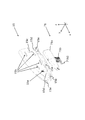
以下、本実施形態について、図を用いて説明する。本実施形態における車載アンテナ装置1は、ルーフなど車両の上面に取り付けられ、ケース10、導光部30、密閉部材50、アンテナ部70、発光部90を備える(図1〜図18参照)。
Hereinafter, this embodiment will be described with reference to the drawings. The vehicle-mounted
方向を説明するために、車載アンテナ装置1が取り付けられる車両の前後方向をx方向、x方向と垂直な左右方向をy方向、x方向とy方向に垂直な略鉛直方向をz方向として説明する。
In order to explain the directions, the front-rear direction of the vehicle to which the vehicle-mounted
ケース10は、アンテナ素子71など車載アンテナ装置1を構成する部材を覆う部材で、外装ケース11、外装パッド13、内装ケース15、アンテナベース17、内装パッド19を有する。
導光部30は、内装ケース15の内部に設けられた発光体91の光を、外装ケース11と内装ケース15の間に導き、外装ケース11の第1開口11aから外部に照射させる部材で、導光板31、拡散板33を有する。
密閉部材50は、内装ケース15の側面を密閉する部材で、Oリング51、接着部材53を有する。
アンテナ部70は、アンテナ素子71、アンテナ基板73を有する。
発光部90は、発光体91、発光体基板93を有する。
The
The
The sealing
The
The
外装ケース11は、非透光性と電波透過性を有する合成樹脂製(ポリカーボネート(Polycarbonate)とASA(Acrylate Styrene Acrylonitrile)を含む合成樹脂などで形成された樹脂成型品)であり、例えば、前方が後方よりも低くなるように傾斜し、両側面が内側に湾曲したシャークフィン形状を有する。
The
外装ケース11は、下面が開口し、車載アンテナ装置1を構成する部材であって、外装ケース11以外のもの(外装パッド13、内装ケース15、アンテナベース17、内装パッド19、導光板31、拡散板33、Oリング51、接着部材53、アンテナ素子71、アンテナ基板73、発光体91、発光体基板93)を、z方向上方から覆う(図2参照)。
The
外装ケース11の側部には、内部からの光を外部に透過させる開口(第1開口11a)が設けられる。
The side portion of the
第1開口11aには、防水などの目的で、透光性と電波透過性を有する合成樹脂で形成された第1窓部(不図示)が取り付けられる形態であってもよいが、本実施形態では、拡散板33が第1開口11aと接触するように内装ケース15に取り付けられるし、第1開口11aを介して浸入した水は、外装パッド13に設けられた排水切欠き13aを介して排出されるので、第1窓部が設けられない形態であってもよい。以下、第1窓部が第1開口11aに取り付けられない形態で説明する。
A first window portion (not shown) made of a synthetic resin having translucency and radio wave transmission may be attached to the
外装ケース11には、内壁からz方向下方に突出するように、アンテナベース17への取り付け用の第1係止爪11bが設けられ、アンテナベース17を外装ケース11に固定する際に、第1係止爪11bは、アンテナベース17に設けられた第2係止爪17aと係合する(図14、図17参照)。
The
外装パッド13は、エラストマー(Elastomer)やゴムなどで形成された環状の弾性部材であり、外装ケース11の下端周縁部に嵌入され、外装ケース11の下端周縁部と車両との間の隙間の目隠しとして機能する。
外装パッド13の下端であって、x方向後方の端部には、外装ケース11と内装ケース15の間に浸入した水の排出口として、排水切欠き13aが設けられる(図14参照)。
The
A
内装ケース15は、非透光性と電波透過性を有する合成樹脂製(ポリカーボネート(Polycarbonate)とASA(Acrylate Styrene Acrylonitrile)を含む合成樹脂などで形成された樹脂成型品)である。
内装ケース15は、下面が開口し、車載アンテナ装置1を構成する部材であって、外装ケース11と外装パッド13と内装ケース15と導光板31と拡散板33とOリング51と接着部材53以外のもの(アンテナベース17、アンテナ素子71、アンテナ基板73、発光体91、発光体基板93)を、z方向上方から覆う。
The
The
内装ケース15の側部には、内部に設けられた発光体91からの光を外部に透過させる開口(第2開口15a)と、導光板31の突起31cを係止するためにy方向外側に突出した略U字形状の突起受け部15bと、導光板31の第1位置決め孔31dが挿入される第1位置決めボス15cと、拡散板33の第2位置決め孔33aや位置決め切欠き33bが挿入される第2位置決めボス15dが設けられる(図2、図3参照)。
位置決め用のボス(第1位置決めボス15cや第2位置決め用ボス15d)は、内装ケース15に設けられる形態であってもよいが、導光板31や拡散板33に設けられる形態であってもよい。
また、拡散板33を位置決めするための第2位置決め用ボス15dは、二以上設けられるのが望ましい。
On the side of the
The positioning bosses (
Further, it is desirable that two or more
第2開口15aには、防水などの目的で、透光性と電波透過性を有する合成樹脂で形成された第2窓部(不図示)が取り付けられる形態であってもよいが、本実施形態では、Oリング51を付けた導光板31の入射部31aが第2開口15aを塞ぐので、第2窓部が設けられない形態であってもよい。以下、第2窓部が第2開口15aに取り付けられない形態で説明する。
A second window portion (not shown) made of a synthetic resin having translucency and radio wave transmission may be attached to the
外装ケース11と内装ケース15とがアンテナベース17に取り付けられた時に、内装ケース15の表面で少なくとも外装ケース11の第1開口11aと対向する部分は、マンセル表示系における明度5以上の色(例えば、白色、灰色、若しくはクリーム色)にされる。
本実施形態では、内装ケース15の全体が白色にされた例を示す。
内装ケース15の下端部には、アンテナベース17とネジ止めするために使用されるネジ孔15eが設けられる。
When the
In this embodiment, an example in which the entire
At the lower end of the
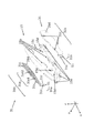
アンテナベース17は、アルミニウム等の金属製ベース、ポリブチレンテレフタレート(Polybutylene Terephthalate)等の樹脂製ベース、若しくはこれらの組み合わせ体(複合体)である。
アンテナベース17は、外装ケース11の第1係止爪11bと係合して外装ケース11を係止する第2係止爪17aを外周部に有する(図9参照)。
The
The
アンテナベース17の上面には、アンテナ基板73と発光体基板93が取り付けられる。
アンテナ基板73は、アンプなどの実装面が鉛直方向を向く(z方向に対して垂直になる)ように配置される。
発光体基板93は、アンテナ素子71やアンテナ基板73よりも前方若しくは後方で且つ、発光体91の投光面や発光体91を駆動する回路の実装面が左右方向を向く(y方向に対して垂直になる)ように配置され、発光体91は、左右両面に実装される。本実施形態では、発光体基板93が、アンテナ素子71やアンテナ基板73よりも前方に配置される形態を示す。
An
The
The
アンテナベース17が内装ケース15に取り付けられた時に、発光体91が内装ケース15の第2開口15aと対向する位置関係になるように、発光体基板93における発光体91の実装位置や発光体基板93がアンテナベース17に取り付けられる位置が決定される。
アンテナベース17の周縁部には、内装ケース15とネジ止めするために使用される凹み(ネジ受け17b)が設けられる。
The mounting position of the illuminant 91 on the
A recess (screw
アンテナベース17の上面の周縁部であって、ネジ受け17bよりも内側には、内装パッド19が取り付けられる。
The
アンテナ基板73や発光体基板93に接続されたケーブル17cは、アンテナベース17に設けられた開口(不図示)を介して、アンテナベース17のz方向下方に延びる(図14、図16、図17参照)。
車載アンテナ装置1の車両の上面への固定は、車体取り付け用ネジ17dをアンテナベース17に螺合させることにより行われる。
アンテナベース17の下面には、エラストマー(Elastomer)やゴムなどで形成された環状の弾性部材であるシール部材17eが設けられ、シール部材17eによりアンテナベース17と車両との間が水密封止される。
The
The in-
A
内装パッド19は、エラストマー(Elastomer)やゴムなどで形成された環状の弾性部材であり、アンテナベース17の上面に設けられる(図9、図17、図18参照)。
内装ケース15とアンテナベース17とがネジ止めにより固定される際に、内装パッド19は、内装ケース15の下端とアンテナベース17の上面によって押圧され、内装ケース15とアンテナベース17の間を密閉する。
アンテナ基板73と発光体基板93は、アンテナベース17における内装パッド19が取り付けられる領域よりも内側に配置される。
The
When the
The
導光板31は、透光性と高屈折率と電波透過性を有する合成樹脂製(ポリカーボネート(Polycarbonate)などの樹脂成型品)である。
導光板31は、発光体91と対向する入射面31a1を有する入射部31aと、反射部31bとで構成され、外装ケース11と内装ケース15の間に取り付けられる(図4〜図8参照)。
The
The
入射部31aと反射部31bとは略直交する位置関係にあり、導光板31は、xy断面が略L字形状を有する。
反射部31bは、前方に配置された発光体91で左(右)方向に発せられた光を後方に誘導(若しくは、後方に配置された発光体91で左(右)方向に発せられた光を前方に誘導)し、一部が第1開口11aと対向する位置関係にあり、誘導した光をy方向等の外側に向けて反射させる。
The
The reflecting
入射部31aや反射部31bには、突起31cが設けられる。
導光板31を内装ケース15に取り付ける際に、入射部31aの突起31cは、内装ケース15の第2開口15aと係合し、反射部31bの突起31cは、内装ケース15の突起受け部15bと係合する。
When the
反射部31bにおける入射部31aから離れた側の端部近傍には、第1位置決め孔31dが設けられ、導光板31を内装ケース15に取り付ける際の位置決めに用いられる。
A
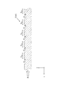
反射部31bにおける内装ケース15への取り付け時に内装ケース15と対向する側の面(内側面)で、少なくともy方向から見て第1開口11aと重なる領域には、xy断面が略V字状若しくは略U字状でz方向に延びる溝(乱反射用パターン)がx方向に複数並べられた溝領域31eが設けられる。
溝領域31eは、第1溝領域31e1と、第1溝領域31e1よりも入射部31aから離れた第2溝領域31e2を有する。
When the
The
第1溝領域31e1では、入射部31aから遠ざかるほど、x方向に隣接する溝の間隔(S11、S12・・・)が狭くなり、且つ溝の深さ(d11、d12・・・)が大きくなるように溝が形成される(S11>S12>S13>S14>S15、d11<d12<d13<d14<d15、図5参照)。
In the first groove region 31e1, as the distance from the
第2溝領域31e2では、x方向に隣接する溝の間隔(S21、S22・・・)は一定で第1溝領域31e1における間隔よりも狭く、且つ入射部31aから遠ざかるほど溝の深さ(d21、d22・・・)が大きくなり第1溝領域31e1における溝の深さよりも大きくなるように溝が形成される(S15>S21=S22=S23=S24=S25=S26、d15<d21<d22<d23<d24<d25<d26、図6参照)。
In the second groove region 31e2, the spacing between the grooves adjacent in the x direction (S 21 , S 22 ...) Is constant and narrower than the spacing in the first groove region 31e1, and the depth of the groove increases as the distance from the
第1溝領域31e1と第2溝領域31e2に設けられた溝のそれぞれは、入射部31aに近い側の傾斜が、入射部31aから遠い側の傾斜に比べて緩くなるように形成される。
Each of the grooves provided in the first groove region 31e1 and the second groove region 31e2 is formed so that the inclination on the side closer to the
第1位置決め孔31dに第1位置決めボス15cが挿入され、入射部31aがOリング51を介して第2開口15aに挿入され、入射部31aの突起31cが第2開口15aに係合し、反射部31bの突起31cが突起受け部15bに係合することで、導光板31が内装ケース15に取り付けられる。
The
入射部31aと第2開口15aの間は、Oリング51によって、密閉される。
The space between the
拡散板33は、透光性と高屈折率と電波透過性を有する合成樹脂製(ポリカーボネート(Polycarbonate)などの樹脂成型品)であり、導光板31における内装ケース15よりも外側にある部分を、y方向外側から覆うように、外装ケース11と内装ケース15の間に取り付けられる(図10〜図12参照)。
The
拡散板33の周縁部には、第2位置決め孔33aや位置決め切欠き33bが設けられ、拡散板33を内装ケース15に取り付ける際の位置決めに用いられる。
A
拡散板33の周縁部の内側であって、拡散板33が内装ケース15に取り付けられ、外装ケース11と内装ケース15とがアンテナベース17に取り付けられた時に、少なくともy方向から見て第1開口11aと重なる領域(中央領域33c)には、反射部31bから照射される光の拡散透過性を高めるため、シボ加工やディンプル加工が施される。
Inside the peripheral edge of the
また、拡散板33が内装ケース15に取り付けられ、外装ケース11と内装ケース15とがアンテナベース17に取り付けられた時に、外装ケース11と拡散板33の間に隙間が形成されないように、シボ加工やディンプル加工などは、拡散板33の中央領域33cにおける導光板31と対向する内面側に施されるのが望ましい。
Further, when the
拡散板33の周縁部であって、第2位置決め孔33aや位置決め切欠き33bよりも内側で、内装ケース15への取り付け時に内装ケース15と対向する部分には、両面テープなど環状に形成された接着部材53を貼り付ける貼付領域33dが設けられる。
拡散板33は、接着部材53を介し、導光板31における内装ケース15よりも外側にある部分を覆うようにして、内装ケース15の側面に貼り付けられる。
接着部材53によって、拡散板33と内装ケース15の間は密着され、内装ケース15の第2開口15aは、Oリング51と接着部材53によって二重に密閉されることになる。
An annular shape such as double-sided tape is formed on the peripheral portion of the
The
The
内装ケース15が外装ケース11に取り付けられた時に、拡散板33の中央領域33cの外側面が外装ケース11の第1開口11aと対向し、第1開口11aの周縁部が拡散板33の中央領域33cの外側面と接する位置関係になるように、導光板31、拡散板33、外装ケース11、内装ケース15の形状などが決定される。
When the
発光体基板93が前方に配置された場合、車載アンテナ装置1の前方において、発光体91からy方向の外側に向けて照射された光は、入射面31a1から入射部31aに入り、略L字形状の部分で後方の反射部31bに誘導され、反射部31bにおける溝領域31eで反射して外側に向けて照射される(一次拡散)。
発光体基板93が後方に配置された場合、車載アンテナ装置1の後方において、発光体91からy方向の外側に向けて照射された光は、入射面31a1から入射部31aに入り、前方に誘導され、反射部31bにおける溝領域31eで反射して外側に向けて照射される。
When the light emitting
When the
反射部31bを通る光の一部は、溝領域31eを透過して内装ケース15の表面に到達するが、明度の高い内装ケース15の外壁で反射して、外側に向けて照射される。
反射部31bから外側に向けて照射された光は、拡散板33の中央領域33cにおけるディンプル等で拡散されて外装ケース11の第1開口11aから外側に照射される(二次拡散)。
A part of the light passing through the reflecting
The light emitted outward from the reflecting
アンテナ素子71は、上部エレメント71aと下部エレメント(波長短縮素子)71bを有し、内装ケース15の内側の上方に、係合爪(不図示)を介して取り付けられる。
上部エレメント71aは、ステンレス等の金属板(導体板)を加工して面状若しくはミアンダ状(meander shape)に形成された部分を有する。
上部エレメント71aのyz断面は、略U字型若しくは略V字型の形状を有する。
下部エレメント71bは、コイル形状を有し、下部エレメント71bの上部71b1を介して、上部エレメント71aと電気的に接続される。
内装ケース15がアンテナベース17に取り付けられる際に、下部エレメント71bの下部端子71b2は、アンテナ素子71が取り付けられた内装ケース15が、アンテナベース17に取り付けられるアンテナ基板73の導体板バネ73aに挟まれて、アンテナ素子71とアンテナ基板73とが電気的に接続可能な状態にされる。
The
The
The yz cross section of the
The
When the
アンテナ素子71は、AM/FM放送の受信用に上部エレメント71aと下部エレメント71bとで構成される形態に限らず、GPS受信用の平面アンテナなどで構成される形態であってもよい。
この場合、アンテナ素子71は、内装ケース15の内側に取り付けられる形態の他、アンテナベース17若しくはアンテナ基板73に取り付けられる形態も考えられる。
The
In this case, the
発光体91は、LEDなどの発光素子を有し、y方向の外側に向かって発光するように発光体基板93に実装される。
発光体基板93は、発光体91や、発光体91を駆動する回路を実装する両面基板であり、少なくとも発光体91は、両面に実装される。
The
The
次に、車載アンテナ装置1の組み立て手順について説明する。
予め、アンテナベース17には、アンテナ基板73と発光体基板93が取り付けられる。
アンテナ素子71が、内装ケース15の内側に取り付けられる(手順1、図2、図3参照)。
導光板31が、内装ケース15の外側に取り付けられる(手順2、図7、図8参照)。
アンテナ素子71を含む内装ケース15が、アンテナベース17に取り付けられ、アンテナ素子71とアンテナ基板73とが電気的に接続可能な状態にされる(手順3、図9参照)。
拡散板33が、内装ケース15の外側に取り付けられる(手順4、図11参照)。
なお、手順3は、手順2の前に行われる形態であってもよいし、手順4の後に行われる形態であってもよい。
外装ケース11が、アンテナベース17に取り付けられる(手順5、図12参照)。
外装パッド13が、外装ケース11に取り付けられ、車載アンテナ装置1が組みあがる(手順6、図13〜図16参照)。
組みあがった車載アンテナ装置1が車両に取り付けられる。
Next, the procedure for assembling the in-
The
The
The
The
The
In addition, the procedure 3 may be a form performed before the procedure 2 or a form performed after the procedure 4.
The
The
The assembled in-
発光体基板93には、銅箔などの金属製の板状部材が含まれているため、近くに配置されたアンテナ素子71の受信性能に悪影響(発光体基板93がある側の受信性能を低下させる)を及ぼすおそれがある。
しかしながら、本実施形態では、発光体基板93が、アンテナ素子71やアンテナ基板73よりも前方又は後方に配置され、且つ発光体基板93の実装面がy方向に垂直になるように立設されるので、実装面がx方向に垂直になるように立設される形態などに比べて、アンテナ素子71の受信性能に悪影響を及ぼしにくい。
このため、アンテナ素子71の特性を維持した状態で、照明装置を車載アンテナ装置1に設けることが可能になる。
Since the
However, in the present embodiment, the
Therefore, the lighting device can be provided in the in-
また、発光体基板93は、実装面がy方向に垂直になるように立設されるので、実装面がx方向に垂直になるように立設される形態やz方向に垂直になるように配置される形態に比べて、y方向の寸法を大きくせずに、車載アンテナ装置1内の空間を有効に用いて、照明装置を車載アンテナ装置1に設けることが可能になる。
Further, since the light emitting
特に、発光体基板93がアンテナ素子71やアンテナ基板73よりも前方に配置された場合には、前方に比べてy方向やz方向の制約が緩やかでスペースが広い後方の領域に、AM/FM受信用だけでなく、GPS受信用など様々なアンテナ素子、さらにはカメラなどの他の電子機器を配置した状態で、照明装置を車載アンテナ装置1に設けることが可能になる。
また、発光体基板93の両面に発光体91を配置して、一方の面に配置された発光体91を前方から見て右の発光用に用い、他方の面に配置された発光体91を前方から見て左の発光用に用いることが出来、狭いスペースの中に多くの発光体91(若しくは大きな発光体91)を実装させることが可能になる。
In particular, when the
Further, the
発光体91がx方向で後方に向かって(若しくは前方に向かって)発光するように発光体基板93に実装される形態で、輝度を上げるために発光体91の数を増やす場合には、発光体91がz方向かy方向かその両方に並べられることになり、これによって実装する発光体基板93におけるy方向の寸法が増える可能性がある。
しかしながら、内装ケース15や外装ケース11のy方向の寸法は、x方向やz方向に比べて狭い場合が多く、y方向に多くの発光体91を配置することは容易ではない。
In a form in which the
However, the dimensions of the
これに対して本実施形態では、発光体91は、y方向の外側に向かって発光するように発光体基板93に実装され、発光体91と対向する位置に入射面31a1が配置され、xy断面が略L字形状で、反射を使って後方に光を導く導光板31を使って、発光体91よりも後方で面状に発光させる。
若しくは、発光体91は、y方向の外側に向かって発光するように発光体基板93に実装され、発光体91と対向する位置に入射面31a1が配置され、xy断面が略L字形状で、反射を使って前方に光を導く導光板31を使って、発光体91よりも前方で面状に発光させる。
このため、輝度を上げるために発光体91の数を増やす場合には、発光体91がz方向かx方向かその両方に並べられるが、これによって実装する発光体基板93におけるy方向の寸法は増えない。
従って、本実施形態では、発光体91がx方向で後ろ側に向かって発光するように発光体基板93に実装される形態に比べて、多くの発光体91を配置することが可能になり、外部に照射される光を明るくすることが可能になる。
On the other hand, in the present embodiment, the
Alternatively, the
Therefore, when increasing the number of light emitting
Therefore, in the present embodiment, it is possible to arrange
また、内装ケース15の表面で少なくとも外装ケース11の第1開口11aと対向する部分は、明度が高い色(例えば、白色などマンセル表示系における明度5以上の色)にされる。
このため、導光板31の反射部31bを透過して内装ケース15の表面に到達した光を、内装ケース15の表面で反射させることが出来、内装ケース15の表面を明度が高い色にしなかった形態に比べて、外部に照射される光を明るくすることが可能になる。
Further, at least a portion of the surface of the
Therefore, the light that has passed through the reflecting
また、発光体91からの光を一次拡散させる導光板31は、xy断面が略V字状若しくは略U字状でz方向に延びる溝がx方向に複数並べられた溝領域31eを有する。
入射部31aに近い第1溝領域31e1は、入射部31aから遠ざかるほど、x方向に隣接する溝の間隔Sが狭くなり、且つ溝の深さdが大きくなるように溝が形成される。
入射部31aから離れた第2溝領域31e2は、x方向に隣接する溝の間隔Sは一定で第1溝領域31e1における間隔よりも狭く、且つ入射部31aから遠ざかるほど溝の深さdが大きくなり第1溝領域31e1における溝の深さdよりも大きくなるように溝が形成される。
第1溝領域31e1と第2溝領域31e2に設けられた溝のそれぞれは、入射部31aに近い側の傾斜が、入射部31aから遠い側の傾斜に比べて緩くなるように形成される。
導光板31の溝形状を上述の構成にすることにより、導光板31からy方向等の外側に発する光が均一な輝度になるようにすることが可能になる。
Further, the
In the first groove region 31e1 close to the
In the second groove region 31e2 away from the
Each of the grooves provided in the first groove region 31e1 and the second groove region 31e2 is formed so that the inclination on the side closer to the
By making the groove shape of the
また、内装ケース15の内側に、アンテナ素子71など、アンテナ機能を確保するための部材と、発光体91など発光に必要な電気的な部材を収納し、内装ケース15の外側に導光板31と拡散板33とが取り付けられ、外装ケース11がこれらを覆う。
このため、外装ケース11と外装パッド13以外の部材を変えずに、外装ケース11と外装パッド13を異なるデザインのものに取り替えて使用することが出来、外観デザイン設計の自由度を高めることが可能になる。
また、第1開口11aの形状を変えれば、導光板31や拡散板33を介して光る領域の形状が変わるので、見た目の印象を大きく変えることが出来る。
Further, a member for ensuring the antenna function such as an
Therefore, the
Further, if the shape of the
また、導光板31で一次拡散した光をさらに二次拡散させる拡散板33の周縁部の内側であって、少なくともy方向から見て第1開口11aと重なる領域(中央領域33c)には、シボ加工やディンプル加工が施される。
これらの構成を含む導光板31と拡散板33を組み合わせることにより、発光体91の光を、車載アンテナ装置1の外側に向かって発するように導光・拡散を効率良く行うことが可能になる。
Further, in the region (
By combining the
また、内装ケース15内の発光体91からの光を外部に照射させるために、内装ケース15の側面に第2開口15aが設けられるが、第2開口15aは、Oリング51を取り付けた導光板31の入射部31aで密閉され、さらに、内装ケース15の側面に取り付けられた導光板31は、拡散板33と接着部材53とで密閉される。
このため、第2開口15aの防水を確実に行うことが出来、外装ケース11から内部に水などが浸入した場合でも、内装ケース15の内部への浸入を防ぐことが出来る。
さらに、拡散板33と接着部材53が、導光板31における内装ケース15よりも外側にある部分を覆い、内装ケース15と拡散板33の間を介した水の浸入を防ぐことで、導光板31を保護することも可能になる。
Further, in order to irradiate the outside with the light from the
Therefore, the
Further, the
また、拡散板33が外装ケース11の第1開口11aに接触するように、外装ケース11がアンテナベース17に取り付けられるので、第1開口11aに透光性を有する窓部を設けずとも、第1開口11aから内部に水などが浸入しにくく出来る。
Further, since the
また、通常の車載アンテナ装置では、内部に水が入りにくくする防水構造は考慮されているが、内部に入ってしまった水を排出する構造まで考慮されていないことが多い。
これに対して、本実施形態では、外装ケース11の下端に取り付けられた外装パッド13の後端には、排水切欠き13aが設けられるので、第1開口11aなどから内部に水が浸入したとしても、排水切欠き13aを介して、外部に排出させることが可能になる。
特に、車載アンテナ装置1が取り付けられる車両のルーフは、後方が低くなるように傾斜しているので、重力により後方に設置された排水切欠き13aを介して、排出されやすい。
また、第1開口11aに窓部を設ける必要が無いため、外装ケース11を非透光性の単一素材で形成することが出来るメリットもある。
Further, in a normal in-vehicle antenna device, a waterproof structure that makes it difficult for water to enter the inside is considered, but in many cases, a structure that discharges the water that has entered the inside is not considered.
On the other hand, in the present embodiment, since the
In particular, since the roof of the vehicle to which the in-
Further, since it is not necessary to provide a window portion in the
なお、排水切欠き13aを設けることのメリットは、外装ケース11に設けた第1開口11aを介して内部からの光を透過させる形態に限らない。
例えば、車載アンテナ装置1にカメラなどの受光装置(不図示)を設け、第1開口11aを介して外部からの光を透過させ、当該受光装置で透過した光を受光(撮影)する形態が考えられる。第1開口11aは、外装ケース11の側面だけでなく、前面や背面や上面に設けられる形態も考えられる。
この場合、当該受光装置やその前面を覆うレンズなどのカバーの一部が第1開口11aと接触して、水の浸入を防ぐことも考えられるが、第1開口11aなどから内部に水が浸入したとしても、排水切欠き13aを介して、外部に排出させることが可能になる。
The merit of providing the
For example, an in-
In this case, it is conceivable that a part of the cover such as the light receiving device and the lens covering the front surface thereof comes into contact with the
1 車載アンテナ装置
10 ケース
11 外装ケース
11a 第1開口(側面開口)
11b 第1係止爪
13 外装パッド
13a 排水切欠き
15 内装ケース
15a 第2開口(凹み開口)
15b 突起受け部
15c 第1位置決めボス
15d 第2位置決めボス
15e ネジ孔
17 アンテナベース
17a 第2係止爪
17b ネジ受け
17c ケーブル
17d 車体取り付け用ネジ
17e シール部材
19 内装パッド
30 導光部
31 導光板
31a 入射部
31a1 入射面
31b 反射部
31c 突起
31d 第1位置決め孔
31e 溝領域
31e1 第1溝領域
31e2 第2溝領域
33 拡散板
33a 第2位置決め孔
33b 位置決め切欠き
33c 中央領域
33d 貼付領域
50 密閉部材
51 Oリング
53 接着部材
70 アンテナ部
71 アンテナ素子
71a 上部エレメント
71b 下部エレメント
71b1 上部
71b2 下部端子
73 アンテナ基板
73a 導体板バネ
90 発光部
91 発光体
93 発光体基板
1 In-
11b
15b
Claims (11)
前記アンテナ素子から得られた信号を増幅するアンテナ基板と、
前記アンテナ基板が取り付けられたアンテナベースと、
平板状であり、発光体を実装する発光体基板と、
前記アンテナベースに取り付けられ、前記アンテナ素子と前記アンテナ基板と前記発光体基板とを覆い、前記発光体からの光を外部に透過させる第1開口を有する外装ケースとを備え、
前記発光体は、前記発光体基板の両面に実装され、
前記発光体基板は、前記発光体を実装する実装面が左右方向を向くように配置されることを特徴とする車載アンテナ装置。 Antenna element and
An antenna substrate that amplifies the signal obtained from the antenna element, and
And the antenna base before Symbol antenna substrate is attached,
A flat plate-like, and the light emitter substrate for mounting a light emission body,
Attached to the front Symbol antenna base, the antenna element and covers said antenna substrate and the light-emitting substrate, and an outer case having a first opening for transmitting light from the light emitter to the outside,
The illuminant is mounted on both sides of the illuminant substrate.
The light-emitting substrate-vehicle antenna apparatus mounting surface for mounting the light emitters and said Rukoto disposed so as to face the left right direction.
前記発光体は、外側に向けて光を発する位置関係に配置されることを特徴とする請求項1に記載の車載アンテナ装置。 Further comprising an inner instrumentation case to the inside of the outer casing,
Before SL emitters, vehicle-mounted antenna device according to claim 1, characterized in that it is arranged in a positional relationship that emits light toward the outer side.
前記第1溝領域は、前記入射部から遠ざかるほど、隣接する溝の間隔が狭くなり、且つ深さが大きくなるように前記溝が形成され、
前記第2溝領域は、隣接する溝の間隔は一定で前記第1溝領域における間隔よりも狭く、且つ前記入射部から遠ざかるほど深さが大きくなり前記第1溝領域における前記溝の深さよりも大きくなるように前記溝が形成され、
前記第1溝領域と前記第2溝領域に設けられた溝のそれぞれは、前記入射部に近い側の傾斜が、前記入射部から遠い側の傾斜に比べて緩くなるように形成されることを特徴とする請求項5に記載の車載アンテナ装置。 The groove region has a first groove region and a second groove region that is farther from the incident portion than the first groove region.
Wherein the first groove region, farther from the incident portion, the interval of the adjacent contact groove is narrowed, it said groove so and depth increases formed,
It said second trench region, the spacing of adjacent contact groove is narrower than the interval in said first trench region at a constant, than and depth of the grooves in the as the depth away from the incident portion increases the first groove region The groove is formed so as to be large,
Each of the first groove region and the groove provided in the second groove region is formed so that the inclination on the side near the incident portion is gentler than the inclination on the side far from the incident portion. The vehicle-mounted antenna device according to claim 5 .
前記内装ケースと、前記アンテナベースとの間は、環状の弾性部材で構成された内装パッドで密閉され、
前記内装ケースは、第2開口を有し、
前記第2開口は、前記入射部と、前記入射部に取り付けられたOリングとで密閉されることを特徴とする請求項2に記載の車載アンテナ装置。 The interior case contains the antenna element and has a built-in antenna element.
The interior case and the antenna base are sealed by an interior pad made of an annular elastic member.
The interior case has a second opening and
The vehicle-mounted antenna device according to claim 2, wherein the second opening is sealed by the incident portion and an O-ring attached to the incident portion.
前記拡散板の周縁部の内側であって、少なくとも前記左右方向から見て前記第1開口と重なる領域には、シボ加工若しくはディンプル加工が施されることを特徴とする請求項3に記載の車載アンテナ装置。 A diffusion plate is provided between the outer case and the light guide plate.
The vehicle-mounted vehicle according to claim 3 , wherein a region that is inside the peripheral edge of the diffusion plate and that overlaps with the first opening at least when viewed from the left-right direction is subjected to grain processing or dimple processing. Antenna device.
前記外装ケースと前記導光板の間には、拡散板が設けられ、
前記拡散板の周縁部の内側であって、少なくとも前記左右方向から見て前記第1開口と重なる領域には、シボ加工若しくはディンプル加工が施され、
前記拡散板は、前記導光板の少なくとも一部を覆うように、前記内装ケースに取り付けられ、
前記拡散板と前記内装ケースの間は、密閉されることを特徴とする請求項2に記載の車載アンテナ装置。 Further provided with a light guide plate for guiding the light emitted by the light emitter,
A diffuser plate is provided between the outer case and the light guide plate.
The area inside the peripheral edge of the diffusion plate, which overlaps with the first opening when viewed from the left-right direction at least, is textured or dimple-processed.
Before SL diffuser, as before covering at least a portion of Kishirubekoban, attached to the interior casing,
Between the interior casing and the diffuser board antenna device according to claim 2, characterized in that it is tightly closed.
前記外装パッドの下端には、排水切欠きが設けられることを特徴とする請求項1に記載の車載アンテナ装置。
Attached to the lower peripheral edge of the front Kigaiso case, further comprising an outer pad disposed between said outer casing and vehicles,
Wherein the lower end of the exterior pad, vehicle-mounted antenna device according to claim 1, characterized in that provided drainage notch.
Priority Applications (2)
| Application Number | Priority Date | Filing Date | Title |
|---|---|---|---|
| JP2016170394A JP6779713B2 (en) | 2016-08-31 | 2016-08-31 | In-vehicle antenna device |
| PCT/JP2017/027976 WO2018043011A1 (en) | 2016-08-31 | 2017-08-02 | Vehicle-mounted antenna device |
Applications Claiming Priority (1)
| Application Number | Priority Date | Filing Date | Title |
|---|---|---|---|
| JP2016170394A JP6779713B2 (en) | 2016-08-31 | 2016-08-31 | In-vehicle antenna device |
Publications (3)
| Publication Number | Publication Date |
|---|---|
| JP2018037914A JP2018037914A (en) | 2018-03-08 |
| JP2018037914A5 JP2018037914A5 (en) | 2019-10-03 |
| JP6779713B2 true JP6779713B2 (en) | 2020-11-04 |
Family
ID=61301914
Family Applications (1)
| Application Number | Title | Priority Date | Filing Date |
|---|---|---|---|
| JP2016170394A Active JP6779713B2 (en) | 2016-08-31 | 2016-08-31 | In-vehicle antenna device |
Country Status (2)
| Country | Link |
|---|---|
| JP (1) | JP6779713B2 (en) |
| WO (1) | WO2018043011A1 (en) |
Families Citing this family (3)
| Publication number | Priority date | Publication date | Assignee | Title |
|---|---|---|---|---|
| WO2019057554A1 (en) | 2017-09-20 | 2019-03-28 | Motherson Innovations Company Ltd. | An antenna housing, a combined antenna and indicator module and a vehicle |
| US11799186B2 (en) | 2017-09-20 | 2023-10-24 | Motherson Innovations Company Limited | Antenna housing, a combined antenna and indicator module and a vehicle |
| CN112689205A (en) * | 2020-12-18 | 2021-04-20 | 深圳数联天下智能科技有限公司 | Router |
Family Cites Families (5)
| Publication number | Priority date | Publication date | Assignee | Title |
|---|---|---|---|---|
| JP4626547B2 (en) * | 2006-03-22 | 2011-02-09 | 株式会社デンソー | In-vehicle dielectric antenna and method for adjusting resonance frequency of antenna element |
| JP2008162391A (en) * | 2006-12-27 | 2008-07-17 | Koito Mfg Co Ltd | Vehicular lamp |
| JP2011245934A (en) * | 2010-05-25 | 2011-12-08 | Honda Motor Co Ltd | Device for indicating driving intention |
| JP5824440B2 (en) * | 2012-10-16 | 2015-11-25 | 株式会社ホンダロック | Vehicle antenna with light emitter |
| JP6511258B2 (en) * | 2014-12-13 | 2019-05-15 | 株式会社ヨコオ | Automotive antenna device |
-
2016
- 2016-08-31 JP JP2016170394A patent/JP6779713B2/en active Active
-
2017
- 2017-08-02 WO PCT/JP2017/027976 patent/WO2018043011A1/en active Application Filing
Also Published As
| Publication number | Publication date |
|---|---|
| WO2018043011A1 (en) | 2018-03-08 |
| JP2018037914A (en) | 2018-03-08 |
Similar Documents
| Publication | Publication Date | Title |
|---|---|---|
| JP6700659B2 (en) | Antenna device | |
| US7230195B2 (en) | Button waterproofing structure | |
| JP6779713B2 (en) | In-vehicle antenna device | |
| JP5582082B2 (en) | Electronic equipment | |
| JP6511258B2 (en) | Automotive antenna device | |
| EP2675140B1 (en) | Electronic device and assembly method of the same | |
| JP4946998B2 (en) | Vehicle lighting device | |
| JP6969527B2 (en) | Light emitting device | |
| JP2019158588A (en) | Limited reflection type sensor | |
| CN110118997B (en) | Door switch | |
| KR102156035B1 (en) | Terminal module for vehicle | |
| KR20170041564A (en) | Multimedia data transfering apparatus | |
| CN109782253B (en) | Laser radar cover | |
| JP6998684B2 (en) | Transmitter with indicator light | |
| JP2008226755A (en) | Lamp for vehicle | |
| JP2014026000A (en) | Emblem light-emitting device | |
| JP2008198657A (en) | Electronic equipment provided with light-emitting diode | |
| JP2018037914A5 (en) | ||
| JP6769339B2 (en) | Display device | |
| JP6646326B2 (en) | Electronic unit | |
| JP6012836B1 (en) | LED lighting device | |
| JP6966513B2 (en) | Transmitter and how to install the transmitter | |
| JP7115103B2 (en) | ETC antenna | |
| JP7253569B2 (en) | Device | |
| US11885479B2 (en) | Light-emitting emblem |
Legal Events
| Date | Code | Title | Description |
|---|---|---|---|
| A521 | Request for written amendment filed |
Free format text: JAPANESE INTERMEDIATE CODE: A523 Effective date: 20190820 |
|
| A621 | Written request for application examination |
Free format text: JAPANESE INTERMEDIATE CODE: A621 Effective date: 20190820 |
|
| TRDD | Decision of grant or rejection written | ||
| A01 | Written decision to grant a patent or to grant a registration (utility model) |
Free format text: JAPANESE INTERMEDIATE CODE: A01 Effective date: 20200918 |
|
| A61 | First payment of annual fees (during grant procedure) |
Free format text: JAPANESE INTERMEDIATE CODE: A61 Effective date: 20201014 |
|
| R150 | Certificate of patent or registration of utility model |
Ref document number: 6779713 Country of ref document: JP Free format text: JAPANESE INTERMEDIATE CODE: R150 |
|
| R250 | Receipt of annual fees |
Free format text: JAPANESE INTERMEDIATE CODE: R250 |