JP6779687B2 - Electronic devices and control methods for electronic devices - Google Patents
Electronic devices and control methods for electronic devices Download PDFInfo
- Publication number
- JP6779687B2 JP6779687B2 JP2016145604A JP2016145604A JP6779687B2 JP 6779687 B2 JP6779687 B2 JP 6779687B2 JP 2016145604 A JP2016145604 A JP 2016145604A JP 2016145604 A JP2016145604 A JP 2016145604A JP 6779687 B2 JP6779687 B2 JP 6779687B2
- Authority
- JP
- Japan
- Prior art keywords
- power saving
- control unit
- power
- controller
- sata
- Prior art date
- Legal status (The legal status is an assumption and is not a legal conclusion. Google has not performed a legal analysis and makes no representation as to the accuracy of the status listed.)
- Active
Links
Images


Classifications
-
- G—PHYSICS
- G06—COMPUTING; CALCULATING OR COUNTING
- G06F—ELECTRIC DIGITAL DATA PROCESSING
- G06F1/00—Details not covered by groups G06F3/00 - G06F13/00 and G06F21/00
- G06F1/26—Power supply means, e.g. regulation thereof
- G06F1/32—Means for saving power
- G06F1/3203—Power management, i.e. event-based initiation of a power-saving mode
-
- G—PHYSICS
- G06—COMPUTING; CALCULATING OR COUNTING
- G06F—ELECTRIC DIGITAL DATA PROCESSING
- G06F3/00—Input arrangements for transferring data to be processed into a form capable of being handled by the computer; Output arrangements for transferring data from processing unit to output unit, e.g. interface arrangements
- G06F3/12—Digital output to print unit, e.g. line printer, chain printer
- G06F3/1201—Dedicated interfaces to print systems
- G06F3/1202—Dedicated interfaces to print systems specifically adapted to achieve a particular effect
- G06F3/1203—Improving or facilitating administration, e.g. print management
- G06F3/1204—Improving or facilitating administration, e.g. print management resulting in reduced user or operator actions, e.g. presetting, automatic actions, using hardware token storing data
-
- G—PHYSICS
- G06—COMPUTING; CALCULATING OR COUNTING
- G06F—ELECTRIC DIGITAL DATA PROCESSING
- G06F1/00—Details not covered by groups G06F3/00 - G06F13/00 and G06F21/00
- G06F1/26—Power supply means, e.g. regulation thereof
-
- G—PHYSICS
- G06—COMPUTING; CALCULATING OR COUNTING
- G06F—ELECTRIC DIGITAL DATA PROCESSING
- G06F1/00—Details not covered by groups G06F3/00 - G06F13/00 and G06F21/00
- G06F1/26—Power supply means, e.g. regulation thereof
- G06F1/32—Means for saving power
- G06F1/3203—Power management, i.e. event-based initiation of a power-saving mode
- G06F1/3206—Monitoring of events, devices or parameters that trigger a change in power modality
- G06F1/3209—Monitoring remote activity, e.g. over telephone lines or network connections
-
- G—PHYSICS
- G06—COMPUTING; CALCULATING OR COUNTING
- G06F—ELECTRIC DIGITAL DATA PROCESSING
- G06F1/00—Details not covered by groups G06F3/00 - G06F13/00 and G06F21/00
- G06F1/26—Power supply means, e.g. regulation thereof
- G06F1/32—Means for saving power
- G06F1/3203—Power management, i.e. event-based initiation of a power-saving mode
- G06F1/3206—Monitoring of events, devices or parameters that trigger a change in power modality
- G06F1/3215—Monitoring of peripheral devices
-
- G—PHYSICS
- G06—COMPUTING; CALCULATING OR COUNTING
- G06F—ELECTRIC DIGITAL DATA PROCESSING
- G06F1/00—Details not covered by groups G06F3/00 - G06F13/00 and G06F21/00
- G06F1/26—Power supply means, e.g. regulation thereof
- G06F1/32—Means for saving power
- G06F1/3203—Power management, i.e. event-based initiation of a power-saving mode
- G06F1/3234—Power saving characterised by the action undertaken
- G06F1/3237—Power saving characterised by the action undertaken by disabling clock generation or distribution
-
- G—PHYSICS
- G06—COMPUTING; CALCULATING OR COUNTING
- G06F—ELECTRIC DIGITAL DATA PROCESSING
- G06F1/00—Details not covered by groups G06F3/00 - G06F13/00 and G06F21/00
- G06F1/26—Power supply means, e.g. regulation thereof
- G06F1/32—Means for saving power
- G06F1/3203—Power management, i.e. event-based initiation of a power-saving mode
- G06F1/3234—Power saving characterised by the action undertaken
- G06F1/324—Power saving characterised by the action undertaken by lowering clock frequency
-
- G—PHYSICS
- G06—COMPUTING; CALCULATING OR COUNTING
- G06F—ELECTRIC DIGITAL DATA PROCESSING
- G06F1/00—Details not covered by groups G06F3/00 - G06F13/00 and G06F21/00
- G06F1/26—Power supply means, e.g. regulation thereof
- G06F1/32—Means for saving power
- G06F1/3203—Power management, i.e. event-based initiation of a power-saving mode
- G06F1/3234—Power saving characterised by the action undertaken
- G06F1/325—Power saving in peripheral device
- G06F1/3284—Power saving in printer
-
- G—PHYSICS
- G06—COMPUTING; CALCULATING OR COUNTING
- G06F—ELECTRIC DIGITAL DATA PROCESSING
- G06F1/00—Details not covered by groups G06F3/00 - G06F13/00 and G06F21/00
- G06F1/26—Power supply means, e.g. regulation thereof
- G06F1/32—Means for saving power
- G06F1/3203—Power management, i.e. event-based initiation of a power-saving mode
- G06F1/3234—Power saving characterised by the action undertaken
- G06F1/3287—Power saving characterised by the action undertaken by switching off individual functional units in the computer system
-
- G—PHYSICS
- G06—COMPUTING; CALCULATING OR COUNTING
- G06F—ELECTRIC DIGITAL DATA PROCESSING
- G06F3/00—Input arrangements for transferring data to be processed into a form capable of being handled by the computer; Output arrangements for transferring data from processing unit to output unit, e.g. interface arrangements
- G06F3/12—Digital output to print unit, e.g. line printer, chain printer
- G06F3/1201—Dedicated interfaces to print systems
- G06F3/1202—Dedicated interfaces to print systems specifically adapted to achieve a particular effect
- G06F3/1218—Reducing or saving of used resources, e.g. avoiding waste of consumables or improving usage of hardware resources
- G06F3/1221—Reducing or saving of used resources, e.g. avoiding waste of consumables or improving usage of hardware resources with regard to power consumption
-
- G—PHYSICS
- G06—COMPUTING; CALCULATING OR COUNTING
- G06F—ELECTRIC DIGITAL DATA PROCESSING
- G06F3/00—Input arrangements for transferring data to be processed into a form capable of being handled by the computer; Output arrangements for transferring data from processing unit to output unit, e.g. interface arrangements
- G06F3/12—Digital output to print unit, e.g. line printer, chain printer
- G06F3/1201—Dedicated interfaces to print systems
- G06F3/1223—Dedicated interfaces to print systems specifically adapted to use a particular technique
- G06F3/1237—Print job management
- G06F3/1253—Configuration of print job parameters, e.g. using UI at the client
- G06F3/1254—Automatic configuration, e.g. by driver
-
- G—PHYSICS
- G06—COMPUTING; CALCULATING OR COUNTING
- G06F—ELECTRIC DIGITAL DATA PROCESSING
- G06F3/00—Input arrangements for transferring data to be processed into a form capable of being handled by the computer; Output arrangements for transferring data from processing unit to output unit, e.g. interface arrangements
- G06F3/12—Digital output to print unit, e.g. line printer, chain printer
- G06F3/1201—Dedicated interfaces to print systems
- G06F3/1278—Dedicated interfaces to print systems specifically adapted to adopt a particular infrastructure
- G06F3/1285—Remote printer device, e.g. being remote from client or server
-
- G—PHYSICS
- G05—CONTROLLING; REGULATING
- G05B—CONTROL OR REGULATING SYSTEMS IN GENERAL; FUNCTIONAL ELEMENTS OF SUCH SYSTEMS; MONITORING OR TESTING ARRANGEMENTS FOR SUCH SYSTEMS OR ELEMENTS
- G05B19/00—Programme-control systems
- G05B19/02—Programme-control systems electric
- G05B19/04—Programme control other than numerical control, i.e. in sequence controllers or logic controllers
- G05B19/042—Programme control other than numerical control, i.e. in sequence controllers or logic controllers using digital processors
-
- G—PHYSICS
- G05—CONTROLLING; REGULATING
- G05B—CONTROL OR REGULATING SYSTEMS IN GENERAL; FUNCTIONAL ELEMENTS OF SUCH SYSTEMS; MONITORING OR TESTING ARRANGEMENTS FOR SUCH SYSTEMS OR ELEMENTS
- G05B2219/00—Program-control systems
- G05B2219/20—Pc systems
- G05B2219/25—Pc structure of the system
- G05B2219/25291—Set module, component to sleep if no event or no other module needs it
-
- Y—GENERAL TAGGING OF NEW TECHNOLOGICAL DEVELOPMENTS; GENERAL TAGGING OF CROSS-SECTIONAL TECHNOLOGIES SPANNING OVER SEVERAL SECTIONS OF THE IPC; TECHNICAL SUBJECTS COVERED BY FORMER USPC CROSS-REFERENCE ART COLLECTIONS [XRACs] AND DIGESTS
- Y02—TECHNOLOGIES OR APPLICATIONS FOR MITIGATION OR ADAPTATION AGAINST CLIMATE CHANGE
- Y02D—CLIMATE CHANGE MITIGATION TECHNOLOGIES IN INFORMATION AND COMMUNICATION TECHNOLOGIES [ICT], I.E. INFORMATION AND COMMUNICATION TECHNOLOGIES AIMING AT THE REDUCTION OF THEIR OWN ENERGY USE
- Y02D10/00—Energy efficient computing, e.g. low power processors, power management or thermal management
-
- Y—GENERAL TAGGING OF NEW TECHNOLOGICAL DEVELOPMENTS; GENERAL TAGGING OF CROSS-SECTIONAL TECHNOLOGIES SPANNING OVER SEVERAL SECTIONS OF THE IPC; TECHNICAL SUBJECTS COVERED BY FORMER USPC CROSS-REFERENCE ART COLLECTIONS [XRACs] AND DIGESTS
- Y02—TECHNOLOGIES OR APPLICATIONS FOR MITIGATION OR ADAPTATION AGAINST CLIMATE CHANGE
- Y02D—CLIMATE CHANGE MITIGATION TECHNOLOGIES IN INFORMATION AND COMMUNICATION TECHNOLOGIES [ICT], I.E. INFORMATION AND COMMUNICATION TECHNOLOGIES AIMING AT THE REDUCTION OF THEIR OWN ENERGY USE
- Y02D30/00—Reducing energy consumption in communication networks
- Y02D30/50—Reducing energy consumption in communication networks in wire-line communication networks, e.g. low power modes or reduced link rate
Description
本発明は、電子機器及び電子機器の制御方法に関する。 The present invention relates to electronic devices and methods for controlling electronic devices.
近年、地球温暖化等の環境問題対応として各国の規制は年々厳しくなってきている。印刷装置においても例外ではなく、真摯に環境問題に取り組み、各種エネルギー関連規格への積極的な対応が求められている。また、ノートPC(パーソナルコンピュータ)やタブレットPCなどのモバイル系電子機器の普及に伴い、バッテリによる駆動をより長時間にする必要がある。そのため、内部バスIF(インターフェース)規格であるPCIe(PCI Express)やストレージデバイスとのIF規格であるSATA(Serial ATA)では、規格レベルにおいて省電力状態が策定されている。例えば、SATAでは、従来からの省電力系コマンドに加えて、ホストとデバイス間IFでの省電力状態が追加された。前者としてはStandbyコマンドやSleepコマンドなどが、後者としてはPartial、Slumber及びDevice−Sleep(以下、DevSleepと示す)が省電力状態として定義されている。ストレージデバイスの代表例として、ハードディスク装置(以下、HDDと示す)やSSD(ソリッドステートドライブ)などが挙げられる。DevSleepは、特にSSDに対して設けられた省電力状態であり、SATA−IF電力と本体電力の両方をRunTimeに削減することを可能とする。 In recent years, regulations in each country have become stricter year by year in response to environmental problems such as global warming. Printing equipment is no exception, and it is required to seriously tackle environmental problems and actively respond to various energy-related standards. In addition, with the spread of mobile electronic devices such as notebook PCs (personal computers) and tablet PCs, it is necessary to drive the batteries for a longer period of time. Therefore, in PCIe (PCI Express), which is an internal bus IF (interface) standard, and SATA (Serial ATA), which is an IF standard for storage devices, a power saving state is established at the standard level. For example, in SATA, in addition to the conventional power saving system command, the power saving state in the IF between the host and the device has been added. The former is defined as a Standby command, a Sleep command, and the like, and the latter is defined as a power saving state of Partial, Slumber, and Device-Sleep (hereinafter referred to as DevSleep). Typical examples of storage devices include hard disk devices (hereinafter referred to as HDDs) and SSDs (solid state drives). DevSleep is a power saving state particularly provided for SSD, and makes it possible to reduce both SATA-IF power and main body power to RunTime.
SATA−IF及びそれに接続されるストレージデバイスは、アクセス期間以外のアイドル状態において比較的に待機電力が大きな部分である。特に、SATAブリッジ構成としてRAID(Redundant Arrays of Inexpensive Disk)制御やデータ暗号化処理を実施する場合である。その場合、ホスト側であるSATAメイン制御部及びデバイス側であるSATAブリッジ制御部のCPUシステムと複数のストレージデバイス及びそれらを接続する複数のSATA−IF(特に物理層)での待機電力は大きなものとなる。そのため、RumTimeな省電力制御が求められる。例えば、PATA(Parallel ATA)−IFを有するHDDとSATA−IFを持つSATAホスト制御部をブリッジする目的のSATAブリッジ構成において、上位メインCPUの手を煩わせることの方法が提案されている。特許文献1では、HDDへの省電力制御状況(SATAブリッジ制御部への省電力系コマンド)に応じて、SATAホスト制御部とデバイス側であるSATAブリッジ制御部間のSATA−IFをPartialやSlumberの省電力状態に移行させる。
The SATA-IF and the storage device connected to it have a relatively large standby power in an idle state other than the access period. In particular, this is a case where RAID (Redundant Arrays of Inexperience Disk) control or data encryption processing is performed as a SATA bridge configuration. In that case, the standby power of the CPU system of the SATA main control unit on the host side and the SATA bridge control unit on the device side, a plurality of storage devices, and a plurality of SATA-IFs (particularly the physical layer) connecting them is large. It becomes. Therefore, RumTime power saving control is required. For example, in a SATA bridge configuration for the purpose of bridging an HDD having PATA (Parallel ATA) -IF and a SATA host control unit having SATA-IF, a method of bothering the upper main CPU has been proposed. In
特許文献1は、HDDへの省電力系コマンドを基点としたSATA系省電力移行処理を行う。すなわち、省電力移行条件は、装置全体の電力ステートとは連動せず、あくまでもSATA系部分のみでの省電力移行判定となるため、きめ細かな省電力制御には限界がある。例えば、HDDは、不要時に電源オフし、真に必要な場合にのみ電源オンすることが電力的及び寿命的に望ましい。また、RAID制御に伴うバックグラウンド処理中の省電力移行要求に対して、現状のバックグラウンド処理を継続するのか、中断するのかの適切な判断を必要とする場合がある。しかしながら、特許文献1では、HDD電源オフ/オンタイミングやバックグラウンド処理の継続の有無を適切に判断することは困難である。
本発明の目的は、ストレージデバイス(例えばHDD)のオフ/オン回数に対する寿命を考慮しつつ効率的に消費電力を削減することができる電子機器及び電子機器の制御方法を提供することである。 An object of the present invention is to provide an electronic device and a control method for the electronic device, which can efficiently reduce power consumption while considering the life of the storage device (for example, HDD) with respect to the number of times of off / on.
本発明の電子機器は、通常の電力状態から複数の省電力状態に遷移可能な電子機器であって、ストレージデバイスと、少なくとも1つのプロセッサと少なくとも1つのメモリを含む第1コントローラと、所定の通信規格に従う所定の物理通信インターフェースを介して前記第1コントローラ及び前記ストレージデバイスと通信する第2コントローラとを有し、前記電子機器が前記複数の省電力状態のうちのいずれかの省電力状態に移行することに従って、前記第1コントローラは、前記移行する省電力状態に応じた省電力モードに前記第2コントローラを移行させ、省電力モードに移行した前記第2コントローラは、前記ストレージデバイスの電源をオフにし、且つ、前記電子機器が前記複数の省電力状態のうちのいずれかの省電力状態から復帰することに従って、前記第1コントローラは、前記第2コントローラを前記省電力モードから復帰させ、復帰した前記第2コントローラは、第1コマンドを受け付けたことに基づいて前記ストレージデバイスの電源をオンさせ、前記第1コマンドと異なる第2コマンドを受け付けたことに基づいて前記ストレージデバイスの電源をオンさせない。 The electronic device of the present invention is an electronic device capable of transitioning from a normal power state to a plurality of power saving states, and is a predetermined communication with a storage device, a first controller including at least one processor and at least one memory. It has a first controller and a second controller that communicates with the storage device via a predetermined physical communication interface according to a standard, and the electronic device shifts to one of the plurality of power saving states. As a result, the first controller shifts the second controller to the power saving mode according to the shifting power saving state, and the second controller shifted to the power saving mode turns off the power of the storage device. And, as the electronic device returns from the power saving state of any one of the plurality of power saving states, the first controller returns the second controller from the power saving mode and returns. The second controller turns on the power of the storage device based on the reception of the first command, and does not turn on the power of the storage device based on the reception of the second command different from the first command .
ストレージデバイス(例えばHDD)のオフ/オン回数に対する寿命を考慮しつつ効率的に消費電力を削減することができる。 Power consumption can be efficiently reduced while considering the life of the storage device (for example, HDD) with respect to the number of times of off / on.
図1は、本発明の実施形態による印刷システムの構成例を示す図である。印刷システムは、印刷装置及び外部HOSTコンピュータ107を有する。印刷装置は、メインコントローラ120と、スキャナ装置109と、HDD/SSD113,114と、パネル装置116と、印刷部118とを有する。印刷装置は、電子機器である。以下、電子機器の例として、印刷装置について説明する。メインCPU(中央処理演算器)101は、メイン制御部であり、システム制御や各種演算処理を行う。メモリ制御部102は、各種メモリデバイスへの入出力制御やDMA(ダイレクト・メモリ・アクセス)制御を行う。フラッシュメモリ103は、書き換え可能な不揮発性メモリであり、システム全体の制御プログラムや制御パラメータ等が格納される。DRAM(ダイナミック・ランダム・アクセス・メモリ)104は、DDR(Double−Data−Rate)メモリに代表される揮発性の書き換え専用メモリである。DRAM104は、プログラムの作業領域や印刷データの格納領域、各種テーブル情報格納領域等の用途に用いられる。ここで、メモリ制御部102と各種メモリデバイスとの関係は、簡略化して表現したものであって、一般的には独立に制御される。LAN−IF制御部105は、印刷装置に接続されるローカル・エリア・ネットワーク106との入出力制御を行う。LAN−IF制御部105は、一般的にはTCP/IP(Transmission Control Protocol/Internet Protocol)プロトコルに対応する。LAN−IF制御部105は、ネットワークケーブルを介して外部HOSTコンピュータ107などのネットワーク対応機器と接続され、ネットワーク経由でのプリントを行うことができる。Reader−IF制御部108は、スキャナ装置109との通信制御を行う。印刷装置は、スキャナ装置109によってスキャンした入力画像データを印刷させることでコピー機能を実現する。画像処理部110は、LAN−IF制御部105、Reader−IF制御部108を介して取り込んだ画像データに対して各種画像処理を行う。SATAホスト制御部111は、SATA(Serial Advanced Technology Attachment)規格に準拠したIFを有するデバイスとのデータ入出力制御を行う。SATAブリッジ制御部112は、上流側としてSATAホスト制御部111にデバイスとして接続され、下流側としては複数のHost−IFを有し、HDD又はSSD113、114と接続される。SATAブリッジ制御部112は、RAID制御やデータ暗号化などの付加価値としての機能が搭載されている。SATA制御部121は、SATAホスト制御部111及びSATAブリッジ制御部112を有する通信制御手段であり、所定の通信規格に従う所定の物理通信インターフェースを介してメインCPU101及びデバイス113,114と通信する。所定の通信規格は、例えばSATA規格である。本実施形態では、SATAホスト制御部111とSATAブリッジ制御部112は、それぞれ独立したASIC(特定用途向け集積回路)としてメインコントローラ120に搭載されていることを前提として説明を行う。パネルIF制御部115は、パネル装置116との通信制御を行う。パネル装置116は、UI(ユーザ・インターフェース)として、パネル上の液晶画面表示やボタン等を操作することにより印刷装置の各種設定及び状態の確認ができる。ビデオ出力IF部117は、印刷部118に対して、コマンド/ステータスの通信制御や印刷データの転送を行う。印刷部118は、印刷装置本体と給紙系及び排紙系から構成され、主にビデオ出力IF部117からのコマンド情報に従い、印刷データを紙に印刷する。メインバス119は、バスコントローラを含み、制御バス、データバス及び任意ブロック間のローカルバスを便宜的にまとめて表現したものであり、代表例としてPCIe(PCI Express)やASICの内部バスなども含まれる。
FIG. 1 is a diagram showing a configuration example of a printing system according to an embodiment of the present invention. The printing system includes a printing apparatus and an
図2は、SATAブリッジ構成の接続例を示す図である。メインASIC201は、SATAホスト制御部111を含むメインコントローラ120のシステム全体を制御する中心的なASICである。SATAホスト制御部111は、1個のSATA−IP(Intellectual Property)202をホストIFとして有する。サブASICは、SATAブリッジ制御部112そのものであり、メインコントローラ120上に独立したIC(Integrated Circuit)として実装されている。SATAブリッジ制御部112は、3個のSATA−IP203〜205を有する。ブリッジ構成の上流側では、SATA−IP(Host)202がH−Host−IF206を介してSATA−IP(Device)203と接続される。ブリッジ構成の下流側では、SATA−IP(Host1)204がB−Host1−IF207を介してHDD/SSD113と接続され、SATA−IP(Host2)205がB−Host2−IF208を介してHDD/SSD114と接続されている。ここで、SATA−IP202〜205は、SATAリンク層及び物理層から構成される。SATA−IP202〜205は、各種SATAレジスタの設定に応じてSATA−IF206〜208で接続されるSATAデバイスに対して物理的な(電気信号としての)SATA規格のコマンド発行やステータス受信を行う。
FIG. 2 is a diagram showing a connection example of a SATA bridge configuration. The
また、SATAブリッジ制御部112は、電源制御部209と制御信号214で接続されている。電源制御部209は、メインボード上に搭載され、メインコントローラ120に含まれる各機能モジュールやそれに接続される各種装置への電力供給の有無を決定し、印刷装置全体としての電源制御を担っている。電源制御部209から出ている一点斜線210〜213は、システム全体の部分であるSATAブリッジ部の各構成要素に対する電源ラインを示したものである。なお、本実施形態では、SATAホスト制御部111及びブリッジ制御部112間のIFを1個、SATAブリッジ制御部112及びHDD/SSD113,114間のIFを2個として説明するが、各IFの数は任意個数の接続形態であってもよい。
Further, the SATA
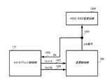
図12は、図2で接続構成を説明したSATAブリッジ制御部112と電源制御部209間のHDD/SSD電源制御を行う制御信号214を分解して、より詳細に示した図である。制御信号IN1205は、SATAブリッジ制御部112への入力信号であり、制御信号OUTA1201及びOUTB1202は、電源制御部209への出力信号である。また、電源制御部209からはHDD/SSDへ電力を供給する電源回路1204への電力供給を許可するEN信号1203が出力されている。電源回路1204は、例えば、DC−DC電源(直流入力直流出力電源)やFET(電界効果トランジスタ)などが挙げられる。EN信号1203は、制御信号IN1205と接続されていて、HDD/SSDへの電力供給状態、すなわち、電源オフかオンかの判定用モニタ信号としてSATAブリッジ制御部112に入力されている。制御信号OUTA1201及びOUTB1202は、HDD/SSDの電源をオフ/オンするための電源制御部209への要求信号である。
FIG. 12 is a diagram showing in more detail by disassembling the
図13は、制御信号IN1205、OUTA1201及びOUTB1202のタイミングチャートである。全ての信号は、開始点1304でローレベル開始処理されることを前提としている。制御信号IN1205は、HDD/SSDの電源のオフ又はオン状態を示すモニタ信号であり、起動後、時点1305でHDDの電源オンとなったことを表している。制御信号OUTA1201は、電源制御部209に対してHDD/SSD電源のオフ又はオン要求を行う有効期間を示す信号である。制御信号OUTA1201がハイレベルの区間1306〜1308が電源制御部209に対してHDD/SSD電源のオフ又はオンを要求する期間である。制御信号OUTB1202は、HDD/SSD電源に対するオン又はオフ要求を行う信号であり、ハイレベル区間が電源オン要求を示し、ローレベル区間が電源オフ要求を示している。図13の例では、区間1306〜1307では制御信号OUTAがハイレベル、制御信号OUTBがローレベルなので、HDD電源がオフされる。区間1306〜1307では、モニタ信号である制御信号INがローレベルとなっており、確かにHDD/SSD電源はオフされていることが読み取れる。同様に、制御信号OUTAがハイレベルの有効期間に制御信号OUTB1202をハイレベル/ローレベルにさせた結果に連動して、制御信号IN1205がハイレベル/ローレベルになっていることが分かる。なお、図12及び図13を用いて説明した例では、モニタ信号である制御信号IN1205及び電源オフ/オン要求信号である制御信号OUTB1202は1対1の関係であったが、これに限定されない。SATAブリッジ制御部112に接続される複数のストレージデバイスのそれぞれに対してモニタ信号(=電源EN信号)INnと電源オフ/オン要求信号OUTBn(n≧2)として、同一番号nを対応させて個別に制御してもよい。
FIG. 13 is a timing chart of the control signals IN1205, OUTA1201 and OUTB1202. It is assumed that all signals will be low-level start processed at the
図3は、SATAホスト制御部111及びSATAブリッジ制御部112の内部構成例を示す図である。SATAホスト制御部111は、第1のSATA制御部であり、メインバス119を介してメインCPU101に接続される。SATAブリッジ制御部112は、第2のSATA制御部であり、H−Host−IF(第1のインターフェース)206を介してSATAホスト制御部111に接続される。HDD/SSD113は、デバイスであり、B−Host1−IF(第2のインターフェース)207を介してSATAブリッジ制御部112に接続される。HDD/SSD114は、デバイスであり、B−Host2−IF(第2のインターフェース)208を介してSATAブリッジ制御部112に接続される。
FIG. 3 is a diagram showing an example of internal configurations of the SATA
HCPU301は、SATAコマンド発行処理、送受信データの転送処理及びステータス受信処理等のSATAコントローラとしての全般的な制御を行う。メモリ制御部302は、フラッシュメモリ303やSRAM(スタティック・ランダム・アクセス・メモリ)304との入出力制御を行う。フラッシュメモリ303には、ブートプログラムやSATAコントローラとしての制御プログラムが格納されている。SRAM304は、HCPU301の作業領域、各種制御テーブルやパラメータ格納領域及びデータバッファなどに使用される。ここで、SRAM304は、1ポートRAM、2ポートRAM、FIFO(First−IN First−OUT)メモリ等の制御を簡略化して記載しているのであって、それぞれ独立に制御され複数個所にSRAMが存在してもよい。割り込み制御部305は、HCPU301に対する割り込み信号の入力や出力処理、割り込み信号に対するマスク処理などを行う。レジスタH306は、省電力関連の制御パラメータなどを一時的に記憶するためのレジスタである。DMAC(ダイレクト・メモリ・アクセス・コントローラ)307は、HCPU301によって所定のレジスタに転送元及び転送先の先頭アドレス及びサイズが設定され、起動が掛けられると所定のメモリ間でデータ転送を行う。Hバス308は、バスコントローラを含み、制御バス、データバス及び任意ブロック間のローカルバスを便宜的にまとめて表現したものである。バスブリッジ回路309は、メインバス119とHバス308間のバスプロトコルを相互に変換するバスブリッジ回路である。
The
BCPU310は、SATAコマンド発行処理、送受信データの転送処理及びステータス受信処理等のSATAコントローラとしての全般的な制御を行う。メモリ制御部311は、フラッシュメモリ312やSRAM313との入出力制御を行う。フラッシュメモリ312には、ブートプログラムやSATAコントローラとしての制御プログラムが格納されている。SRAM313は、BCPU310の作業領域、各種制御テーブルやパラメータ格納領域及びデータバッファなどに使用される。ここで、SRAM313は、1ポートRAM、2ポートRAM、FIFOメモリ等の制御を簡略化して記載しているのであって、それぞれ独立に制御され複数個所にSRAMが存在してもよい。レジスタB314は、省電力関連の制御パラメータなどを一時的に記憶するためのレジスタである。電源IF部315は、電源制御部209と制御信号214で接続され、HDD/SSD113、114への電源オフ/オン要求信号の制御を行う。Others316は、SATAブリッジ制御部112としての他の機能ブロック、例えばRAID処理やデータ暗号化処理等をまとめて示したものである。Bバス317は、バスコントローラを含み、制御バス、データバス及び任意ブロック間のローカルバスを便宜的にまとめて表現したものである。また、図2で説明したように、SATAホスト制御部111のSATA−IP(Host)202とSATAブリッジ制御部112のSATA−IP(Device)203とは、H−Host−IF206で接続されている。さらに、SATA−IP(Host1/2)204及び205は、B−Host1/2−IF207及び208を介して、HDD/SSD113及び114に接続されている。
The
図4は、メインコントローラ120の電力ステートを横軸に示し、SATA系省電力状態と省電力移行条件を縦軸として示したものである。図4の第1行目は、印刷装置全体としての上位電力ステート401を示しており、消費電力が高い順にStandby(スタンバイ)モード402、Sleep(スリープ)モード403、Deep(ディープ)モード404と定義する。Standbyモード402は、印刷装置が直ちにジョブを受け付け可能な状態であり、図1のメインコントローラ120、スキャナ装置109、パネル装置116、印刷部118及びHDD/SSD113、114には全て通電され、基本的にアイドル状態である。Sleepモード403及びDeepモード404は、印刷装置の省電力状態であり、ジョブ実行をしていない期間の待機電力削減を目的とする。Sleepモード403では、Standbyモード402で説明した部位は通電されているが、基本的に省電力状態である。特に、Deepモード404は、大半部分の電力供給をカットした状態であり、図1のメモリ制御部102及びDRAM104、LAN−IF105、パネルIF115及びパネル装置116に通電されている。Deepモード404は、Sleepモード403での各部省電力状態よりもさらに深い省電力状態に置かれ、それら以外は全て電源オフ状態である。本実施形態の対象であるSATAホスト制御部111、SATAブリッジ制御部112及び接続デバイスであるHDD/SSD113、114も、Deepモード404では全て電源オフされた状態であることを前提としている。さらに、上位電力ステート401に対応するSATA系省電力状態としてPowerSave0(PS0)407、PowerSave1(PS1)408及びPowerSave2(PS2)409を定義する。PS0(407)〜PS2(409)は、図4で示すように上位電力ステートに対応したものであり、電力削減効果としてはPS0<PS1<PS2(電源オフ)の関係となる。また、そのトレードオフとして復帰時間は、不等号が逆転する関係となる。各SATA系省電力状態におけるH−Host−IF206の省電力移行条件を項目411〜413、B−Host1/2−IF207及び208の省電力移行条件を項目415〜417、HDD/SSD本体の省電力移行条件を項目419〜421として定義する。各項目411〜421の設定値で、図に“/”で区切られた内容は、その中のいずれかひとつが設定されることを示している。但し、設定値の個数(すなわち、とり得る状態数)は任意に追加してもよい。また、図4の省電力設定値としてのH−Host−IF状態410、B−Host−IF状態414、HDD/SSD本体状態418の対応個所を図2に示す。それらは、それぞれにH−Host−IF206(202及び203を含む)、B−Host1/2−IF207及び208(204及び205を含む)、HDD/SSD113及び114に対応する。PS0(407)〜PS2(409)の状態遷移した場合に項目411〜421の設定値の状態に各対応部が置かれることを意味する。ここで、省電力移行条件としてとり得る省電力状態について説明する。AIはActive−Idle、LPIはLow−Power−Idleであり、アイドル状態におけるSATA−IFと接続デバイス本体のATA規格で定義されている電力状態を示す。既に説明したように、Partial/SlumberはSATA−IFとして、DevSleepはSATA−IF及びデバイス本体の両方の省電力状態をSATA規格で定義されたものである。また、OffLineは、SATA−IPとしての無効(停止)状態を示す。一般的にSATA−IFの省電力として効果が高い順番に並べるとOffLine>DevSleep>Slumber>Partial>LPI>AI、同様にデバイス本体の省電力としては電源オフ>DevSleep>LPI>AIとなる。ここで、接続するデバイスの電源オフ指示の設定条件に、電源オフ−1と電源オフ−2を項目419及び420に設け、次の定義を与える。電源オフ−1は、次回復帰時にデバイス本体の電源オンを伴わない(省電力&寿命優先)。電源オフ−2は、次回復帰と同時にデバイス本体も電源オンする(利便性優先)。電源オフ−1及び電源オフ−2によって、特にHDDの電源オフ/オン寿命を配慮した省電力制御が可能となる。後述するが、省電力移行条件は、SATAホスト制御部111及びSATAブリッジ制御部112の起動時に予め設定されることになる。また、SATAホスト制御部111のHCPUシステム及びSATAブリッジ制御部112のBCPUシステム自身の各省電力効果も一般的には復帰時間とのトレードオフとしてPS0<PS1<PS2(電源オフ)の関係と同じとするのが最適解である。ただし、PS0≦PS1<PS2の関係でもよい。HCPU301及びBCPU310自身の省電力手段として、クロックゲートや電源分離による部分的な電源供給カットなどの方法がある。
In FIG. 4, the power state of the
ここで、図4で説明した例では、印刷装置全体の電力ステート数を3段階、それに対応するSATA系省電力状態を3段階としたが、電力ステート数やSATA系省電力状態数は任意であってよい。さらに、B−Host1/2−IF207及び208の省電力移行条件を項目415〜417とし、HDD/SSD本体の省電力移行条件を項目419〜421としてが、接続ポート単位で個別に設定してもよい。
Here, in the example described with reference to FIG. 4, the number of power states of the entire printing apparatus is set to 3 stages, and the corresponding SATA power saving states are set to 3 stages, but the number of power states and the number of SATA power saving states are arbitrary. It may be there. Further, the power saving transition conditions of B-Host1 / 2-IF207 and 208 are set to
図5は、図4で説明した各省電力移行条件を予めSATAブリッジ制御部112に設定するための拡張コマンドについて示す図である。SATA規格で定義された空コマンドであるベンダユニーク・コマンド(例えばF0h)に対して、図5の第1行目左から示されるように拡張コマンド名称501、CMD(サブコマンド)番号502、転送タイプ503として省電力系拡張コマンドを独自に定義する。ここで、CMD番号502は、ベンダユニーク・コマンド(例えば、F0h)に対するFeatureレジスタに設定されるサブコマンド番号を示す。また、SATA規格では、基本的な転送タイプとして、データを伴わないNon−Data(ND)転送、単発データ転送を実行するPIO−In(PI)又はPIO−Out(PO)転送、連続データ転送を実行するDMA転送などの転送タイプが定義されている。図5での転送タイプ503は、CMD番号502に対する転送タイプを定義している。例えば、SetupPowerConfigコマンド505は、CMD番号が01h(506)、転送タイプがPO(507)で構成される。同様に、ToSleepコマンド509は、CMD番号が02h(510)、転送タイプがND(511)で定義されている。ToDeepコマンド513は、CMD番号が03h(514)、転送タイプがND(515)で定義されている。GetStatusコマンド517は、CMD番号が04h(518)、転送タイプがPI(519)で定義されている。
FIG. 5 is a diagram showing an extended command for setting each power saving transition condition described in FIG. 4 in the SATA
SetupPowerConfigコマンド505は、指定内容508に示すように、SATAブリッジ制御部112に、H−Host−IF206の省電力移行条件411〜413を設定するために用いられる。また、SetupPowerConfigコマンド505は、指定内容508に示すように、SATAブリッジ制御部112に、B−Host1/2−IF207及び208の省電力移行条件415〜417を設定するために用いられる。また、SetupPowerConfigコマンド505は、指定内容508に示すように、SATAブリッジ制御部112に、HDD/SSD本体の省電力移行条件419〜421を設定するために用いられる。
The
ToSleepコマンド509は、指定内容512に示すように、上位電力ステートがSleepモード403へ移行することをSATAブリッジ制御部112に通知するコマンドである。ToDeepコマンド513は、指定内容516に示すように、上位電力ステートがDeepモードに移行することをSATAブリッジ制御部112に通知するコマンドである。GetStatusコマンド517は、指定内容520に示すように、SATAブリッジ制御部全般のステータス取得のための拡張コマンドである。これは、直接的な省電力関連の拡張コマンドではないが、例えば省電力移行処理が完了したことを上位システムが取得する場合に用いられる。以後、拡張コマンド以外のATA規格で定義されたコマンドを区別して表現する場合には、ATAコマンドと呼ぶことにする。
The
さらに、幾つかのフロー図を用いて、本実施形態の印刷装置(電子機器)の制御方法について説明する。なお、説明の煩雑性を避けるため、本実施形態に関係しないエラー処理については基本的に説明を省略する。 Further, a control method of the printing apparatus (electronic device) of the present embodiment will be described with reference to some flow charts. In order to avoid complication of the explanation, the explanation of the error processing not related to the present embodiment is basically omitted.
図6は、SATA系省電力制御の初期設定フローを示す図である。メインコントローラ120の起動(コールドブート)時に、以下の処理が行われる。ステップS601では、メインCPU101は、SATAホスト制御部111に対して、複数の省電力状態PS0〜PS2毎に、図4で説明したH−Host−IF206の省電力移行条件411〜413の設定を行う。次に、ステップS602では、メインCPU101は、SATAブリッジ制御部112に対して、SetupPowerConfigコマンド505をSATAホスト制御部111から発行させることで、省電力の初期設定を行う。具体的には、メインCPU101は、SATAブリッジ制御部112に対して、複数の省電力状態PS0〜PS2毎に、図4で説明したB−Host1/2−IF207及び208の省電力移行条件415〜417を設定する。また、メインCPU101は、SATAブリッジ制御部112に対して、複数の省電力状態PS0〜PS2毎に、図4で説明したHDD/SSD113及び114の省電力移行条件419〜421を設定する。SetupPowerConfigコマンド505を受信したBCPU310は、所定の場所に省電力移行条件を記録する。ここで、SATAホスト制御部111及びSATAブリッジ制御部112における省電力移行条件の記録場所としてはレジスタH306やレジスタB314、SRAM304や313、フラッシュメモリ303や312などに設定を行う。この際、省電力移行処理時に読み出せる場所であれば特に限定はしない。また、上記ではメインコントローラ120起動時での初期設定について説明したが、印刷装置がStandbyモード402であれば、同じ設定方法によって任意タイミングで省電力移行条件を再設定してもよい。なお、本実施形態での印刷装置の起動(コールドブート)時は、一端上位電力ステートがStandbyモード402、SATA制御系及びそれに接続されるストレージデバイスがアイドル状態に遷移することを前提とする。
FIG. 6 is a diagram showing an initial setting flow of SATA-based power saving control. The following processing is performed when the
図7は、SATAホスト制御部111の省電力移行シーケンスを示す図である。ステップS701では、HCPU301は、アイドル(待機)状態としてメインCPU101からの割り込み指示待ちである。次に、ステップS702では、メインCPU101は、SATAホスト制御部111に対して、アイドル状態から、省電力効果が異なる複数の省電力状態PS0,PS1,PS2のうちの1つの省電力状態への移行要求割り込みを指示する。HCPU301は、受信した割り込み信号の判定を行う。HCPU301は、その判定結果がPS0移行要求割り込みである(YES)場合には、ステップS703に処理を進め、その判定結果がPS0移行要求割り込みでない(NO)場合には、ステップS705に処理を進める。ステップS703では、HCPU301は、図6のステップS601の設定に応じて、H−Host−IF206に対してアイドル状態から省電力状態PS0(407)への移行処理を行う。すなわち、HCPU301は、SATAブリッジ制御部112に対してアイドル状態から省電力状態PS0への移行を指示する。次に、ステップS704では、HCPU301は、SATAホスト制御部111自身に対してアイドル状態から省電力状態PS0(407)への移行処理を行う。
FIG. 7 is a diagram showing a power saving transition sequence of the SATA
ステップS705では、HCPU301は、判定結果がPS1移行要求割り込みである(YES)場合には、ステップS706に処理を進め、判定結果がPS1移行要求割り込みでない(NO)場合には、ステップS708に処理を進める。ステップS706では、HCPU301は、図6のステップS601の設定に応じて、H−Host−IF206に対してアイドル状態から省電力状態をPS1(408)への移行処理を行う。すなわち、HCPU301は、SATAブリッジ制御部112に対してアイドル状態から省電力状態PS1への移行を指示する。次に、ステップS707では、HCPU301は、SATAホスト制御部111自身に対して、アイドル状態から省電力状態PS1(408)への移行処理を行う。
In step S705, the
ステップS708では、HCPU301は、判定結果がPS2移行要求割り込みである(YES)場合には、ステップS709に処理を進め、判定結果がPS2移行要求割り込みでない(NO)場合には、ステップS711に処理を進める。ステップS709では、HCPU301は、図6のステップS601の設定に応じて、H−Host−IF206に対して、アイドル状態から省電力状態をPS2(409)への移行処理を行う。すなわち、HCPU301は、SATAブリッジ制御部112に対してアイドル状態から省電力状態PS2への移行を指示する。次に、ステップS710では、HCPU301は、SATAホスト制御部111自身に対して、アイドル状態から省電力状態PS2(409)への移行処理を行う。
In step S708, the
ステップS711では、HCPU301は、省電力移行要求以外の割り込みに応じた処理、例えば通常データ転送時のライトコマンド発行処理などを実行し、処理完了した後に再びステップS701に戻り、アイドル状態に入る。なお、HCPU301は、要求のあった省電力状態に移行した後に、移行完了割り込みをメインCPU101に通知すると同時に、レジスタH306の一部を省電力状態のステータスレジスタとして報告する。
In step S711, the
ここで、PS0(407)〜PS2(409)での設定されたH−Host−IF206の省電力移行条件について説明する。Partial及びSlumberは、SATA規格で定義されたリクエストパケットを送信し、送信先が許可すればSATA−IFに対する省電力状態に入ることができる。また、DevSleepは、まずSATA−IFをSlumberに入れて、さらにシングルエンド信号であるDEVSLP信号をイネーブル状態にすることで接続デバイス本体電力を削減することができる。 Here, the power saving transition conditions of the H-Host-IF206 set in PS0 (407) to PS2 (409) will be described. Partial and Slumber transmit the request packet defined in the SATA standard, and can enter the power saving state for SATA-IF if the destination permits. Further, the DevSleep can reduce the power of the connected device main body by first inserting the SATA-IF into the SLMber and then enabling the DEVSLP signal which is a single-ended signal.
図8は、SATAブリッジ制御部112の省電力移行シーケンスを示す図である。ステップS801では、BCPU310は、アイドル状態として待機中である。BCPU310は、基本的にSATAホスト制御部111であるHCPU301からの割り込み指示待ちの状態である。次に、ステップS802では、BCPU310は、受信した割り込み信号がH−Host−IF206の省電力状態への移行の通知(移行を引き起こすイベントが発生した)かどうかの判定を行う。BCPU310は、判定結果がH−Host−IF206の省電力状態への移行の通知である(YES)場合には、ステップS809に処理を進める。また、BCPU310は、判定結果がH−Host−IF206の省電力状態への移行の通知でない(NO)場合には、ステップS803に処理を進める。
FIG. 8 is a diagram showing a power saving transition sequence of the SATA
ステップS803では、BCPU310は、受信した割り込み信号が省電力系の拡張コマンドであるかどうかの判定を行う。BCPU310は、省電力系の拡張コマンドである(YES)の場合には、ステップS805に処理を進め、省電力系の拡張コマンドでない(NO)の場合には、ステップS804に処理を進める。ステップS804では、BCPU310は、他の割り込み処理、例えばATAコマンド処理などを実行し、再びステップS801のアイドル状態に戻る。
In step S803, the
ステップS805では、BCPU301は、受信した省電力系コマンドがToSleepコマンド509かどうかの判定を行う。BCPU301は、ToSleepコマンド509である(YES)の場合には、ステップS806に処理を進め、ToSleepコマンド509でない(NO)場合には、ステップS807に処理を進める。ステップS806では、BCPU310は、上位電力ステートをSleepモード403としてレジスタB314やSRAM313等に登録し、再びステップS801のアイドル状態に戻る。
In step S805, the
ステップS807では、BCPU310は、受信した省電力系コマンドがToDeepコマンド513であると判断し、上位電力ステートをDeepモード403としてレジスタB314やSRAM313等に登録し、ステップS808へ処理を進める。ステップS808では、BCPU310は、Deep移行準備を行い、再びステップS801のアイドル状態に戻る。Deepモード403では、基本的に電源制御部209による電源オフ処理を前提としている。そのため、特に瞬断を許さないストレージデバイス(HDDやSSD)及びフラッシュメモリを内蔵するSATAブリッジ制御部112のようなタイプのICは電源オフ準備を行い、準備完了後に電源オフタイミングを通知する必要がある。PS2状態としての電源オフ準備完了かどうかは、GetStatusコマンド517によって取得することが可能である。メインCPU101は、SATAホスト制御部111やSATAブリッジ制御部112が電源オフ準備完了したことを前述したステータス取得手段により確認した後に、電源制御部209に電源オフ許可を通知する。また、一例としてHDD電源オフ時の準備としては、ATA規格のFLUSH CACHEコマンド及びSLEEPコマンドを発行し、データ退避や物理的なヘッダの退避等を行う。
In step S807, the
ステップS809では、BCPU310は、上位電力ステートがStandbyモード402として予め設定されているH−Host−IF206の省電力移行条件411から、PS0(407)に移行すべきかどうかの判定を行う。BCPU310は、PS0(407)に移行すべき(YES)場合には、ステップS810に処理を進め、PS0(407)に移行すべきでない(NO)場合には、ステップS811に処理を進める。ステップS810では、BCPU310は、予め設定されているB−Host1/2−IF207及び208の省電力移行条件415を基に、B−Host1/2−IF207及び208に対してアイドル状態から省電力状態PS0(407)への移行処理を行う。また、BCPU310は、予め設定されているHDD/SSD本体の省電力移行条件419を基に、HDD/SSD113,114に対してアイドル状態から省電力状態PS0(407)への移行処理を行う。例えば、BCPU310は、電源オフ−1(第1の電源オフモード)又は電源オフ−2(第2の電源オフモード)でHDD/SSD113,114の電源オフを指示する。そして、BCPU310は、SATAブリッジ制御部112自身に対してアイドル状態から省電力状態PS0(407)への移行処理を行う。
In step S809, the
ステップS811では、BCPU310は、上位電力ステートがSleepモード403として予め設定されているH−Host−IF206の省電力移行条件412から、PS1(408)に移行すべきかどうかの判定を行う。BCPU310は、PS1(408)に移行すべき(YES)場合には、ステップS812に処理を進め、PS1(408)に移行すべきでない(NO)場合には、ステップS813に処理を進める。ステップS812では、BCPU310は、予め設定されているB−Host1/2−IF207及び208の省電力移行条件416を基に、B−Host1/2−IF207及び208に対してアイドル状態から省電力状態PS1(408)への移行処理を行う。また、BCPU310は、予め設定されているHDD/SSD本体の省電力移行条件420を基に、HDD/SSD113,114に対してアイドル状態から省電力状態PS1(408)への移行処理を行う。例えば、BCPU310は、電源オフ−1(第1の電源オフモード)又は電源オフ−2(第2の電源オフモード)でHDD/SSD113,114の電源オフを指示する。そして、BCPU310は、SATAブリッジ制御部112自身に対して、アイドル状態から省電力状態PS1(408)への移行処理を行う。
In step S811, the
ステップS813では、BCPU310は、上位電力ステートがDeepモード404として予め設定されているH−Host−IF206の省電力移行条件413から、PS2(409)に移行すべきかどうかの判定を行う。BCPU310は、PS2(409)に移行すべき(YES)場合には、ステップS814に処理を進め、PS2(409)に移行すべきでない(NO)場合には、ステップS815に処理を進める。ステップS814では、BCPU310は、予め設定されているB−Host1/2−IF207及び208の省電力移行条件417を基に、B−Host1/2−IF207及び208に対してアイドル状態から省電力状態PS2(409)への移行処理を行う。また、BCPU310は、予め設定されているHDD/SSD本体の省電力移行条件421を基に、HDD/SSD113,114に対してアイドル状態から省電力状態PS2(409)への移行処理を行う。そして、BCPU310は、SATAブリッジ制御部112自身に対して、アイドル状態から省電力状態PS2(409)への移行処理を行う。ステップS815では、BCPU310は、省電力移行失敗としてエラー処理を行い、上位へのステータス通知等を実行する。
In step S813, the
以上のように、SATAブリッジ制御部112は、PS0(407)〜PS2(409)のいずれかの省電力状態への移行判定を行う。その際、SATAブリッジ制御部112は、上位電力ステート(Standbyモード402、Sleepモード403、Deepモード404)情報とH−Host−IF206の省電力状態の2条件からPS0〜PS2のいずれかであるかを判定する。PS0又はPS1で、HDD/SSD本体の省電力移行条件419〜421が電源オフ指示(電源オフ−1又は電源オフ−2)であった場合には、図12及び図13で説明したようにBCPU310は、電源制御部209にHDD/SSD電源のオフ要求を行う。
As described above, the SATA
図9は、SATAホスト制御部111のPS0(407)又はPS1(408)からの復帰シーケンスを示す図である。ステップS901では、HCPU301は、PS0又はPS1の省電力状態である。次に、ステップS902では、HCPU301は、メインCPU101からの割り込み要求待ち状態であり、割り込み要求がなければ(すなわち、S902のNOであれば)、ステップS901に戻り、PS0又はPS1の省電力状態を継続する。HCPU301は、コマンド転送要求割り込みを受信すると、ステップS903へ処理を進める。すなわち、HCPU301は、メインCPU101により省電力状態PS0又はPS1からアイドル状態への復帰が指示されると、ステップS903に処理を進める。ステップS903では、HCPU301は、SATAホスト制御部111自身に対して省電力状態PS0又はPS1からアイドル状態への復帰処理を行う。次に、ステップS904では、HCPU301は、H−Host−IF206に対して、省電力状態PS0又はPS1からアイドル状態への復帰処理を行う。具体的には、HCPU301は、SATA規格で規定されたOOB(Out Of Band)やスピードネゴシエーションの所定シーケンスを経て、コマンド発行可能となるまでのリンク確立処理を行う。ここで、基本的にSATA−IF系省電力状態からの復帰は、SATA規格で定義されたリセット信号であるComReset信号の発行から開始される。DevSleepからの復帰は、図7で説明した移行の逆手順で、まずDEVSLP信号をディスイネーブルにしてから、次にComReset信号(又はComWake信号)を投げることで開始される。次に、ステップS905では、HCPU301は、リンク確立したことを確認すると、メインCPU101からの要求コマンドをH−Host−IF206に発行する。次に、ステップS906では、HCPU301は、SATA−IP(Device)203からのStatus受信待ちに入る。HCPU301は、未受信の間(S906でNO)はそのまま待機し、Statusを受信(S906でYES)した時点で、一連のコマンド処理を終了し、ステップS907に処理を進める。ステップS907では、メインCPU101によって再び省電力移行要求が発行されるまでの間、SATAホスト制御部111は、アイドル状態を維持する。
FIG. 9 is a diagram showing a return sequence from PS0 (407) or PS1 (408) of the SATA
図10は、SATAブリッジ制御部112のPS0(407)又はPS1(408)からの復帰シーケンスを示す図である。ステップS1001では、BCPU310は、PS0又はPS1の省電力状態である。次に、ステップS1002では、BCPU310は、割り込み要求待ち状態であり、割り込み要求がなければ(すなわち、S1002のNOであれば)、ステップS1001に戻り、PS0又はPS1の省電力状態を継続する。BCPU310は、H−Host−IF206のアイドル状態への復帰処理開始の割り込みを受信(S1002でYES)すると、ステップS1003に処理を進める。すなわち、BCPU310は、省電力状態からの復帰を引き起こすイベントが発生すると、ステップS1003に処理を進める。ここで、復帰処理の開始は、図9で説明したDEVSLP信号がディイネーブルとなるレベル変化の検知やComReset(又はComWake)を要因として割り込み信号が発行される。ステップS1003では、BCPU310は、SATAブリッジ制御部112自身に対して省電力状態PS0又はPS1からアイドル状態への復帰処理を行う。次に、ステップS1004では、BCPU310は、H−Host−IF206に対して省電力状態PS0又はPS1からアイドル状態への復帰処理を行う。具体的には、BCPU310は、SATA規格で規定されたOOB(Out Of Band)やスピードネゴシエーションの所定シーケンスを経て、コマンド発行可能となるまでのリンク確立処理を行う。
FIG. 10 is a diagram showing a return sequence from PS0 (407) or PS1 (408) of the SATA
次に、ステップS1005では、BCPU310は、前回の省電力移行時のデバイス本体移行設定条件が電源オフ−2であったかどうかの判定を行う。ここで、BCPU310は、前回の省電力移行時のデバイス本体の移行設定条件が電源オフ−1又は電源オフ−2なのかを、次回復帰時に判定可能なように記録しておく必要がある。PS0(407)やPS1(408)では、少なくともHCPU301やBCPU310のSATA制御部は省電力状態には移行するが、電源オフにはならないことを前提としている。従って、電源オフ−1か電源オフ−2の判定情報を、例えばレジスタH306やレジスタB314などに記録することが可能である。記録は、次回省電力からの復帰時のみ利用され、復帰した後にクリアされるものとする。BCPU310は、電源オフ−2であった(YES)場合(且つ、IN1205がローレベル)には、ステップS1006に処理を進め、電源オフ−2でなかった(NO)場合には、ステップS1008に処理を進める。すなわち、BCPU310は、電源オフの指示内容に基づきステップS1006に進むか否かを決定する。
Next, in step S1005, the
ステップS1006では、BCPU310は、接続デバイスに対して省電力状態PS0又はPS1からアイドル状態への復帰処理を行う。BCPU310は、接続デバイスであるHDD/SSD113、114の電源をオフしていた場合、図12及び図13で説明したように電源制御部209に対してHDD/SSD電源のオン要求を行う。すなわち、BCPU310は、電源オフ−2である場合にはHDD/SSD113、114の電源オンを指示し、電源オフ−1である場合にはHDD/SSD113、114の電源オンを指示しない。
In step S1006, the
次に、ステップS1007では、BCPU310は、B−Host1/2−IF207及び208に対して省電力状態PS0又はPS1からアイドル状態への復帰処理を行い、ステップS1008に処理を進める。復帰処理に関しては、図9で説明したH−Host−IF206の復帰処理と同様である。
Next, in step S1007, the
ステップS1008では、BCPU310は、リンク確立したことを確認すると、コマンド受信待ちを開始する。この時点で省電力状態からアイドル状態への復帰は完了したことになる。BCPU310は、コマンドを受信していない(NO)場合には、ステップS1008に留まり、受信した(YES)場合には、ステップS1009へ処理を進める。
In step S1008, when the
ステップS1009では、BCPU310は、SATAホスト制御部111から受信したコマンドがATAコマンドかどうかの判定を行う。BCPU310は、ATAコマンドである(YES)場合には、ステップS1011に処理を進め、ATAコマンドでない(NO)場合には、ステップS1010に処理を進める。ステップS1011では、BCPU310は、前回の省電力移行時のデバイス本体移行設定条件が電源オフ−1であったかどうかの判定を行う。BCPU310は、電源オフ−1であった場合(且つ、IN1205がローレベル)には、ステップS1012に処理を進め、電源オフ−1でなかった場合には、ステップS1014に処理を進める。
In step S1009, the
ステップS1012では、BCPU310は、ステップS1006と同様に、接続デバイスであるHDD/SSD113、114に対して省電力状態PS0又はPS1からアイドル状態への復帰処理を行う。BCPU310は、電源オフ−1である場合には、HDD/SSD113、114の電源オンを指示する。次に、ステップS1013では、BCPU310は、ステップS1007と同様に、B−Host1/2−IF207及び208に対して省電力状態PS0又はPS1からアイドル状態への復帰処理を行い、ステップS1014に処理を進める。
In step S1012, the
ステップS1014では、BCPU310は、ATAコマンドの処理を行う。次に、S1015では、HCPU301は、HDD/SSD113、114からのStatus受信待ちに入る。HCPU301は、未受信の間(S1015でNO)はそのまま待機し、Statusを受信(S1015でYES)した時点で、ステップS1016に処理を進める。
In step S1014, the
また、ステップS1009では、BCPU310は、受信コマンドが拡張コマンドである場合には、ステップS1010に処理を進める。ステップS1010では、BCPU310は、拡張コマンド処理を実行し、ステップS1016に処理を進める。
Further, in step S1009, the
ステップS1016では、BCPU310は、HDD/SSDから受信したステータス情報又は拡張コマンドにて処理した結果を、SATA規格で定義されたステータスパケットに反映してSATA−IP(Host)201へ送信する。これにより、BCPU310は、一連のコマンド処理を終了する。次に、ステップS1017では、メインCPU101によって再び省電力移行要求が発行されるまでの間、SATAブリッジ制御部112はアイドル状態を維持する。
In step S1016, the
図11は、SATAブリッジ制御部112のPS2(409)省電状態からの復帰シーケンスを示す図である。ここでの説明では、接続デバイスとしてHDDを前提として説明を行う。ステップS1101では、HCPU301及びBCPU310は、前回のPS2移行処理により電源オフ状態である。その後、電源制御部209は、SATAホスト制御部111及びSATAブリッジ制御部112への電源供給(すなわち、電源オン)を開始する。次に、ステップS1102では、BCPU310は、自身の復帰処理(ブート処理)を実施する。次に、ステップS1103では、BCPU310は、H−Host−IF206の復帰処理を実行する。具体的には、BCPU310のブート処理と同時にHCPU301のブート処理も開始される。H−Host−IF206の復帰処理では、既に説明したようにSATA−IP(Host)202からSATA−IP(Device)203へのComRest信号を基点としたOOB及びスピードネゴシエーション処理を経てリンクが確立される。ステップS1103でのリンク確立後、BCPU310は、SATA下層のリンク確立を実行する。次に、ステップS1104では、BCPU310は、HDD電源供給状態をモニタする制御信号IN1205を確認し、HDD電源のオフ/オン判定を行う。BCPU310は、制御信号INがハイレベルである(YES)場合には、ステップS1105に処理を進め、制御信号INがローレベルである(NO)場合には、ステップS1106に処理を進める。
FIG. 11 is a diagram showing a recovery sequence from the PS2 (409) power saving state of the SATA
ステップS1105では、BCPU310は、電源オフ−2(電源オンを伴う復帰)と認識し、ステップS1107に処理を進める。ステップS1106では、BCPU310は、電源オフ−1(電源オンを伴わない復帰)として認識し、ステップS1107に処理を進める。ここで、GetStatus517では、省電力への移行確認だけでなく、HDDの接続状況なども取得可能である。メインCPU101は、SATAホスト制御部111及びSATAブリッジ制御部112の起動後、所定時間内にHDD接続OK(リンク確立状態)とならない場合にはエラーとして扱う。ここで、GetStatus517でのHDD接続状態確認では、例えば未接続状態1(接続エラー)/未接続状態2(電源オフ−1としての未接続)を区別して確認できるようにする。
In step S1105, the
図14は、GetStatus517で報告される一例を示す。GetStatus517での報告内容1401の一部として、デバイス1接続状態1402とデバイス2接続状態1403とを設け、さらに状態定義1404を示す。例えば、意図的な電源オフ状態での復帰時は“状態:01”としてメインCPU101に報告される。BCPU310は、ステップS1105又はS1106での認識によって、GetStatus517でのHDD接続状態報告を未接続2として適切に示すことができる。未接続2を確認したメインCPU101は、この場合、意図的な未接続として認識し、エラー処理対象としない。
FIG. 14 shows an example reported in
ステップS1107では、BCPU310は、上位層がリンク確立したことを確認すると、コマンドの受信待ちを開始する。この時点で省電力状態からアイドル状態への復帰は完了したことになる。BCPU310は、コマンド未受信の間(NO)はステップS1107に滞在し、コマンドを受信する(YES)と、ステップS1108に処理を進める。
In step S1107, when the
ステップS1108では、BCPU310は、受信したコマンドがATAコマンドかどうかの判定を行う。BCPU310は、ATAコマンドである(YES)場合には、ステップS1110に処理を進め、拡張コマンドである(NO)場合には、ステップS1109に処理を進める。
In step S1108, the
ステップS1110では、BCPU310は、HDD電源供給状態をモニタする制御信号IN1205を確認し、HDD電源のオフ/オン判定を行う。BCPU310は、制御信号IN1205がローレベルである(YES)場合には、ステップS1111に処理を進め、制御信号IN1205がハイレベルである(NO)場合には、ステップS1113に処理を進める。ステップS1111では、BCPU310は、ステップS1006と同様に、接続デバイスの復帰処理を行う。次に、ステップS1112では、BCPU310は、ステップS1007と同様に、B−Host1/2−IF207及び208の復帰処理を行い、ステップS1113に処理を進める。
In step S1110, the
ステップS1113では、BCPU310は、ATAコマンド処理を実行する。次に、ステップS1114では、HCPU301は、HDD113、114からのStatus受信待ちに入る。HCPU301は、未受信の間(S1114でNO)はそのまま待機し、Statusを受信(S1114でYES)した時点で、ステップS1115に処理を進める。また、ステップS1109では、BCPU310は、拡張コマンド処理を実行し、ステップS1115に処理を進める。
In step S1113, the
ステップS1115では、BCPU310は、HDD113、114から受信したステータス情報又は拡張コマンドにて処理した結果を、SATA規格で定義されたステータスパケットに反映してSATA−IP(Host)201へ送信する。これにより、BCPU310は、一連のコマンド処理を終了する。次に、ステップS1116では、メインCPU101によって再び省電力移行要求が発行されるまでの間、SATAブリッジ制御部112はアイドル状態を維持する。
In step S1115, the
以上のように、本実施形態では、アイドル状態及び省電力状態(PS0〜PS2)間、省電力状態間(例えば、PS1及びPS2間)の遷移で、特にHDDにおいて移行条件に電源オフ−1を設定しておく。これにより、ATAコマンド受信時(すなわち、真にHDDを必要とする場合)のみにHDD電源オン制御可能となるため、HDDに対する省電力的、且つ電源オフ/オン回数寿命的にも最適な省電力制御を実施することが可能となる。 As described above, in the present embodiment, in the transition between the idle state and the power saving state (PS0 to PS2) and between the power saving states (for example, between PS1 and PS2), the power off -1 is set as the transition condition especially in the HDD. Set it. As a result, the HDD power-on control can be performed only when the ATA command is received (that is, when the HDD is truly required). Therefore, the power saving for the HDD and the optimum power saving in terms of the number of times the power is turned off / on It becomes possible to carry out control.
なお、上記実施形態は、何れも本発明を実施するにあたっての具体化の例を示したものに過ぎず、これらによって本発明の技術的範囲が限定的に解釈されてはならないものである。すなわち、本発明はその技術思想、又はその主要な特徴から逸脱することなく、様々な形で実施することができる。 It should be noted that all of the above embodiments merely show examples of embodiment in carrying out the present invention, and the technical scope of the present invention should not be construed in a limited manner by these. That is, the present invention can be implemented in various forms without departing from the technical idea or its main features.
101 メインCPU、111 SATAホスト制御部、112 SATAブリッジ制御部、113,114 HDD/SSD 101 main CPU, 111 SATA host control unit, 112 SATA bridge control unit, 113, 114 HDD / SSD
Claims (14)
ストレージデバイスと、
少なくとも1つのプロセッサと少なくとも1つのメモリを含む第1コントローラと、
所定の通信規格に従う所定の物理通信インターフェースを介して前記第1コントローラ及び前記ストレージデバイスと通信する第2コントローラとを有し、
前記電子機器が前記複数の省電力状態のうちのいずれかの省電力状態に移行することに従って、前記第1コントローラは、前記移行する省電力状態に応じた省電力モードに前記第2コントローラを移行させ、省電力モードに移行した前記第2コントローラは、前記ストレージデバイスの電源をオフにし、
且つ、
前記電子機器が前記複数の省電力状態のうちのいずれかの省電力状態から復帰することに従って、前記第1コントローラは、前記第2コントローラを前記省電力モードから復帰させ、復帰した前記第2コントローラは、第1コマンドを受け付けたことに基づいて前記ストレージデバイスの電源をオンさせ、前記第1コマンドと異なる第2コマンドを受け付けたことに基づいて前記ストレージデバイスの電源をオンさせないことを特徴とする電子機器。 An electronic device that can transition from a normal power state to multiple power saving states.
With storage devices
A first controller that includes at least one processor and at least one memory,
It has the first controller and the second controller that communicates with the storage device via a predetermined physical communication interface according to a predetermined communication standard.
As the electronic device shifts to any of the plurality of power saving states, the first controller shifts the second controller to a power saving mode corresponding to the shifting power saving state. The second controller, which has been moved to the power saving mode, turns off the power of the storage device and turns off the power of the storage device.
and,
As the electronic device returns from the power saving state of any of the plurality of power saving states, the first controller returns the second controller from the power saving mode and returns the second controller. Is characterized in that the power of the storage device is turned on based on the reception of the first command, and the power of the storage device is not turned on based on the reception of a second command different from the first command. Electronics.
前記第2コントローラは、前記第1コントローラに接続される第1のSATA制御部と、第1のインターフェースを介して前記第1のSATA制御部に接続される第2のSATA制御部とを含み、
前記ストレージデバイスは、第2のインターフェースを介して前記第2のSATA制御部に接続され、
前記電子機器がアイドル状態から前記複数の省電力状態のうちのいずれかの省電力状態に移行することに従って、前記第1コントローラは、前記移行する省電力状態に応じた省電力モードに前記第1のSATA制御部を移行させ、
前記第1のSATA制御部は、前記第2のSATA制御部を前記省電力モードに移行させ、
前記第2のSATA制御部は、前記省電力モードに移行すると前記ストレージデバイスの電源をオフにする第1の電源オフモード又は第2の電源オフモードに移行させることを特徴とする請求項1記載の電子機器。 The predetermined communication standard is a SATA standard.
The second controller includes a first SATA control unit connected to the first controller and a second SATA control unit connected to the first SATA control unit via a first interface.
The storage device is connected to the second SATA control unit via the second interface.
As the electronic device shifts from the idle state to the power saving state of any one of the plurality of power saving states, the first controller enters the power saving mode according to the shifting power saving state. SATA control unit of
The first SATA control unit shifts the second SATA control unit to the power saving mode.
Said second SATA controller, according to claim 1, wherein the shifting to the first power-off mode or the second power off mode for turning off the power source of the storage device to shift to the power saving mode Electronic equipment.
前記第2のSATA制御部は、前記第1のSATA制御部によりアイドル状態から省電力状態への移行が指示されると、前記第2のインターフェースに対して省電力状態への移行処理を行い、自身に対して省電力状態への移行処理を行うことを特徴とする請求項2記載の電子機器。 When the first controller instructs the first SATA control unit to shift from the idle state to the power saving state, the first SATA control unit performs a transition processing to the power saving state for the first interface and causes itself. And perform the transition process to the power saving state,
When the first SATA control unit instructs the second SATA control unit to shift from the idle state to the power saving state, the second SATA control unit performs a transition process to the power saving state for the second interface. The electronic device according to claim 2, wherein the electronic device itself is subjected to a process of shifting to a power saving state.
前記第1のSATA制御部は、前記第1のインターフェースの省電力移行の設定を基に、前記第1のインターフェースに対して前記移行処理を行い、
前記第2のSATA制御部は、前記第2のインターフェースの省電力移行の設定を基に、前記第2のインターフェースに対して前記移行処理を行い、
前記第2のSATA制御部は、前記ストレージデバイスの省電力移行の設定を基に、前記ストレージデバイスに対して前記移行処理を行うことを特徴とする請求項3記載の電子機器。 The first controller sets the power saving transition of the first interface to the first SATA control unit, and sets the power saving transition of the first interface to the second SATA control unit, and sets the second interface and the storage device to the second SATA control unit. Set the power saving transition and set
The first SATA control unit performs the transition process on the first interface based on the power saving transition setting of the first interface.
The second SATA control unit performs the transition process on the second interface based on the power saving transition setting of the second interface.
It said second SATA controller, based on the setting of the power saving shift of the storage device, the electronic device according to claim 3, characterized in that the transition process to the storage device.
前記電子機器が第1省電力状態に移行することに従って、前記第1コントローラは、前記第2コントローラを第1省電力モードに移行させ、
前記電子機器が前記第1省電力状態よりも消費電力が低い第2省電力状態に移行することに従って、前記第1コントローラは、前記第2コントローラを前記第1省電力モードよりも消費電力が低い第2省電力モードに移行させ、
前記電子機器が前記第2省電力状態よりも消費電力が低い第3省電力状態に移行することに従って、前記第1コントローラは、前記第2コントローラを前記第2省電力モードよりも消費電力が低い第3省電力モードに移行させることを特徴とする請求項1記載の電子機器。 The plurality of power saving states include at least three power saving states.
As the electronic device transitions to the first power saving state, the first controller shifts the second controller to the first power saving mode.
As the electronic device shifts to the second power saving state, which consumes less power than the first power saving state, the first controller consumes the second controller lower than the first power saving mode. Shift to the second power saving mode,
As the electronic device shifts to the third power saving state in which the power consumption is lower than the second power saving state, the first controller consumes the second controller lower than the second power saving mode. The electronic device according to claim 1, wherein the electronic device is shifted to the third power saving mode.
復帰した前記第1のSATA制御部は、前記第2のSATA制御部を前記省電力モードから復帰させ、
前記第2のSATA制御部は、前記省電力モードから復帰する際に、前記ストレージデバイスが前記第1の電源オフモードである場合には前記ストレージデバイスの電源をオンさせず、前記ストレージデバイスが前記第2の電源オフモードである場合には前記ストレージデバイスの電源をオンさせることを特徴とする請求項2記載の電子機器。 As the electronic device recovers from any of the plurality of power saving states, the first controller returns the first SATA control unit from the power saving mode.
The returned first SATA control unit returns the second SATA control unit from the power saving mode.
When returning from the power saving mode, the second SATA control unit does not turn on the power of the storage device when the storage device is in the first power off mode, and the storage device does not turn on the power. The electronic device according to claim 2, wherein the power of the storage device is turned on in the second power-off mode.
前記第2のSATA制御部は、前記第1のSATA制御部により省電力状態からアイドル状態への復帰が指示されると、前記第2のSATA制御部に対してアイドル状態への復帰処理を行い、前記第1のインターフェースに対してアイドル状態への復帰処理を行い、前記第2の電源オフモードである場合には、前記ストレージデバイスに対してアイドル状態への復帰処理を行い、前記第2のインターフェースに対してアイドル状態への復帰処理を行うことを特徴とする請求項3記載の電子機器。 When the first controller instructs the first SATA control unit to return from the power saving state to the idle state, the first SATA control unit performs a return processing to the idle state to the first SATA control unit, and the first Performs the process of returning to the idle state for the interface of 1 and
When the first SATA control unit instructs the second SATA control unit to return to the idle state, the second SATA control unit performs a return process to the idle state for the second SATA control unit. The first interface is returned to the idle state, and in the case of the second power off mode, the storage device is returned to the idle state, and the second power is turned off. The electronic device according to claim 3, wherein the interface is subjected to a process of returning to an idle state.
ストレージデバイスと、
少なくとも1つのプロセッサと少なくとも1つのメモリを含む第1コントローラと、
所定の通信規格に従う所定の物理通信インターフェースを介して前記第1コントローラ及び前記ストレージデバイスと通信する第2コントローラとを有する電子機器の制御方法であって、
前記電子機器が前記複数の省電力状態のうちのいずれかの省電力状態に移行することに従って、前記第1コントローラは、前記移行する省電力状態に応じた省電力モードに前記第2コントローラを移行させ、省電力モードに移行した前記第2コントローラは、前記ストレージデバイスの電源をオフにし、
且つ、
前記電子機器が前記複数の省電力状態のうちのいずれかの省電力状態から復帰することに従って、前記第1コントローラは、前記第2コントローラを前記省電力モードから復帰させ、復帰した前記第2コントローラは、第1コマンドを受け付けたことに基づいて前記ストレージデバイスの電源をオンさせ、前記第1コマンドと異なる第2コマンドを受け付けたことに基づいて前記ストレージデバイスの電源をオンさせないことを特徴とする電子機器の制御方法。 An electronic device that can transition from a normal power state to multiple power saving states.
With storage devices
A first controller that includes at least one processor and at least one memory,
A method for controlling an electronic device having a first controller and a second controller that communicates with the storage device via a predetermined physical communication interface according to a predetermined communication standard.
As the electronic device shifts to any of the plurality of power saving states, the first controller shifts the second controller to a power saving mode corresponding to the shifting power saving state. The second controller, which has been moved to the power saving mode, turns off the power of the storage device and turns off the power of the storage device.
and,
As the electronic device returns from the power saving state of any of the plurality of power saving states, the first controller returns the second controller from the power saving mode and returns the second controller. Is characterized in that the power of the storage device is turned on based on the reception of the first command, and the power of the storage device is not turned on based on the reception of a second command different from the first command. How to control electronic devices.
Priority Applications (4)
| Application Number | Priority Date | Filing Date | Title |
|---|---|---|---|
| JP2016145604A JP6779687B2 (en) | 2016-07-25 | 2016-07-25 | Electronic devices and control methods for electronic devices |
| US15/654,567 US10809781B2 (en) | 2016-07-25 | 2017-07-19 | Electronic device and method for controlling the same |
| CN201710608694.0A CN107656708B (en) | 2016-07-25 | 2017-07-25 | Electronic device and control method thereof |
| US17/023,096 US11204632B2 (en) | 2016-07-25 | 2020-09-16 | Electronic device and method for controlling the same |
Applications Claiming Priority (1)
| Application Number | Priority Date | Filing Date | Title |
|---|---|---|---|
| JP2016145604A JP6779687B2 (en) | 2016-07-25 | 2016-07-25 | Electronic devices and control methods for electronic devices |
Related Child Applications (1)
| Application Number | Title | Priority Date | Filing Date |
|---|---|---|---|
| JP2020172542A Division JP6992142B2 (en) | 2020-10-13 | 2020-10-13 | Electronic devices and control methods for electronic devices |
Publications (3)
| Publication Number | Publication Date |
|---|---|
| JP2018015914A JP2018015914A (en) | 2018-02-01 |
| JP2018015914A5 JP2018015914A5 (en) | 2019-09-05 |
| JP6779687B2 true JP6779687B2 (en) | 2020-11-04 |
Family
ID=60988453
Family Applications (1)
| Application Number | Title | Priority Date | Filing Date |
|---|---|---|---|
| JP2016145604A Active JP6779687B2 (en) | 2016-07-25 | 2016-07-25 | Electronic devices and control methods for electronic devices |
Country Status (3)
| Country | Link |
|---|---|
| US (2) | US10809781B2 (en) |
| JP (1) | JP6779687B2 (en) |
| CN (1) | CN107656708B (en) |
Families Citing this family (2)
| Publication number | Priority date | Publication date | Assignee | Title |
|---|---|---|---|---|
| JP7025945B2 (en) | 2018-01-31 | 2022-02-25 | 株式会社小松製作所 | Motors, rotary drive systems and hydraulic excavators |
| JP7396090B2 (en) * | 2020-02-12 | 2023-12-12 | 京セラドキュメントソリューションズ株式会社 | Image processing device |
Family Cites Families (14)
| Publication number | Priority date | Publication date | Assignee | Title |
|---|---|---|---|---|
| JP4371739B2 (en) | 2003-09-02 | 2009-11-25 | 株式会社東芝 | Electronic device having serial ATA interface and power saving method of serial ATA bus |
| JP5235768B2 (en) * | 2009-04-23 | 2013-07-10 | キヤノン株式会社 | Control device, control method thereof, and program |
| US8417979B2 (en) * | 2010-12-23 | 2013-04-09 | Western Digital Technologies, Inc. | Method and system for progressive power reduction of inactive device while maintaining ready status with host |
| US8443221B2 (en) * | 2011-03-04 | 2013-05-14 | Sandisk Technologies Inc. | Methods, systems, and computer readable media for advanced power management for serial advanced technology attachment (SATA)-based storage devices |
| JP6207123B2 (en) * | 2012-03-09 | 2017-10-04 | セイコーエプソン株式会社 | Printer control method and printer |
| US8959374B2 (en) * | 2012-07-31 | 2015-02-17 | Hewlett-Packard Development Company, L.P. | Power management for devices in a data storage fabric |
| JP2014045302A (en) * | 2012-08-27 | 2014-03-13 | Canon Inc | Image processing device, control method of image processing device, and program |
| JP2014057134A (en) * | 2012-09-11 | 2014-03-27 | Canon Inc | Image forming device, image forming device control method, and program |
| US9213400B2 (en) * | 2013-03-14 | 2015-12-15 | Intel Corporation | Apparatus and method to provide near zero power DEVSLP in SATA drives |
| WO2014141140A1 (en) * | 2013-03-14 | 2014-09-18 | Lsi Corporation | Device power control |
| US20140281621A1 (en) * | 2013-03-15 | 2014-09-18 | Jay Everett Nelson | Stealth power management in storage array |
| KR20150009295A (en) * | 2013-07-16 | 2015-01-26 | 삼성전자주식회사 | Nonvolatile memory device and device sleep state control method thereof |
| JP2015208909A (en) * | 2014-04-25 | 2015-11-24 | 株式会社リコー | Image forming device and power state transition method |
| US9519328B2 (en) * | 2014-05-21 | 2016-12-13 | Intel Corporation | Techniques for selectively reducing power levels of ports and core switch logic in infiniband switches |
-
2016
- 2016-07-25 JP JP2016145604A patent/JP6779687B2/en active Active
-
2017
- 2017-07-19 US US15/654,567 patent/US10809781B2/en active Active
- 2017-07-25 CN CN201710608694.0A patent/CN107656708B/en active Active
-
2020
- 2020-09-16 US US17/023,096 patent/US11204632B2/en active Active
Also Published As
| Publication number | Publication date |
|---|---|
| CN107656708A (en) | 2018-02-02 |
| US11204632B2 (en) | 2021-12-21 |
| US10809781B2 (en) | 2020-10-20 |
| CN107656708B (en) | 2021-10-26 |
| JP2018015914A (en) | 2018-02-01 |
| US20210004069A1 (en) | 2021-01-07 |
| US20180024602A1 (en) | 2018-01-25 |
Similar Documents
| Publication | Publication Date | Title |
|---|---|---|
| KR102320386B1 (en) | Image forming apparatus and power control method for image forming apparatus | |
| JP5597104B2 (en) | Data transfer apparatus and control method thereof | |
| JP5454224B2 (en) | Storage device and storage system | |
| JP5477773B2 (en) | Image forming apparatus | |
| JP6779687B2 (en) | Electronic devices and control methods for electronic devices | |
| JP2010191951A (en) | Electronic device, power saving control method for the same, and program | |
| JP2019127017A (en) | Information processing apparatus, control method therefor, and program | |
| JP6949572B2 (en) | Image forming device that realizes power saving and its control method | |
| JP2014026373A (en) | Information processing device, control method for information processing device, and program | |
| JP4358041B2 (en) | Control device, information processing device, control method, power saving control program, and recording medium | |
| JP6336328B2 (en) | COMMUNICATION DEVICE, ITS CONTROL METHOD, AND PROGRAM | |
| JP6992142B2 (en) | Electronic devices and control methods for electronic devices | |
| JP2011181011A (en) | Data storage device, and low power consumption control method for the same | |
| CN111541825B (en) | Electronic device and control method thereof | |
| JP2014057134A (en) | Image forming device, image forming device control method, and program | |
| JP2006018388A (en) | Information processor, storage device and power management method | |
| JP2012116138A (en) | Control device, control program, and image forming device | |
| JP2007164738A (en) | Data storage device and image processing device | |
| JP4352100B2 (en) | Electronic equipment with serial ATA interface | |
| JP4435260B2 (en) | Electronic equipment with serial ATA interface | |
| JP2006185352A (en) | External storage controller and program for the same | |
| JP2018020549A (en) | Electronic device and method for controlling electronic device | |
| JP2009093679A (en) | Electronic equipment having serial ata interface | |
| JP2008293476A (en) | Interface control circuit, image processing apparatus, and power management method | |
| JP2006040233A (en) | Information processing system and image processing system |
Legal Events
| Date | Code | Title | Description |
|---|---|---|---|
| A521 | Request for written amendment filed |
Free format text: JAPANESE INTERMEDIATE CODE: A523 Effective date: 20190723 |
|
| A621 | Written request for application examination |
Free format text: JAPANESE INTERMEDIATE CODE: A621 Effective date: 20190723 |
|
| A977 | Report on retrieval |
Free format text: JAPANESE INTERMEDIATE CODE: A971007 Effective date: 20200629 |
|
| A131 | Notification of reasons for refusal |
Free format text: JAPANESE INTERMEDIATE CODE: A131 Effective date: 20200707 |
|
| A521 | Request for written amendment filed |
Free format text: JAPANESE INTERMEDIATE CODE: A523 Effective date: 20200903 |
|
| TRDD | Decision of grant or rejection written | ||
| A01 | Written decision to grant a patent or to grant a registration (utility model) |
Free format text: JAPANESE INTERMEDIATE CODE: A01 Effective date: 20200915 |
|
| A61 | First payment of annual fees (during grant procedure) |
Free format text: JAPANESE INTERMEDIATE CODE: A61 Effective date: 20201014 |
|
| R151 | Written notification of patent or utility model registration |
Ref document number: 6779687 Country of ref document: JP Free format text: JAPANESE INTERMEDIATE CODE: R151 |