JP6779110B2 - Vehicle power supply - Google Patents
Vehicle power supply Download PDFInfo
- Publication number
- JP6779110B2 JP6779110B2 JP2016226528A JP2016226528A JP6779110B2 JP 6779110 B2 JP6779110 B2 JP 6779110B2 JP 2016226528 A JP2016226528 A JP 2016226528A JP 2016226528 A JP2016226528 A JP 2016226528A JP 6779110 B2 JP6779110 B2 JP 6779110B2
- Authority
- JP
- Japan
- Prior art keywords
- protector
- harness
- battery module
- path
- detection
- Prior art date
- Legal status (The legal status is an assumption and is not a legal conclusion. Google has not performed a legal analysis and makes no representation as to the accuracy of the status listed.)
- Active
Links
Images

Classifications
-
- Y—GENERAL TAGGING OF NEW TECHNOLOGICAL DEVELOPMENTS; GENERAL TAGGING OF CROSS-SECTIONAL TECHNOLOGIES SPANNING OVER SEVERAL SECTIONS OF THE IPC; TECHNICAL SUBJECTS COVERED BY FORMER USPC CROSS-REFERENCE ART COLLECTIONS [XRACs] AND DIGESTS
- Y02—TECHNOLOGIES OR APPLICATIONS FOR MITIGATION OR ADAPTATION AGAINST CLIMATE CHANGE
- Y02T—CLIMATE CHANGE MITIGATION TECHNOLOGIES RELATED TO TRANSPORTATION
- Y02T10/00—Road transport of goods or passengers
- Y02T10/60—Other road transportation technologies with climate change mitigation effect
- Y02T10/70—Energy storage systems for electromobility, e.g. batteries
Landscapes
- Battery Mounting, Suspending (AREA)
- Connection Of Batteries Or Terminals (AREA)
- Electric Propulsion And Braking For Vehicles (AREA)
- Arrangement Or Mounting Of Propulsion Units For Vehicles (AREA)
- Details Of Indoor Wiring (AREA)
Description
本発明は電動車に使用される車両用電源装置に関する。 The present invention relates to a vehicle power supply device used in an electric vehicle.
モータを駆動源とした電気自動車やハイブリッド自動車などの電動車においてモータに電力を供給する車両用電源装置が使用されている。
車両用電源装置は、高圧の直流電力をモータに供給することから複数の電池セルを直列に接続した電池モジュールを複数個に接続して構成された組電池を備えている。
組電池は、複数の電池モジュールが一方向に並べられた複数の電池モジュール列で構成されている(特許文献1参照)。
また、車両用電源装置は、各電池モジュールの電圧(充電状態)などの電池モジュールの状態を検出しその検出結果を上位のECUに伝達する電池管理装置を備えている(特許文献2参照)。
ところで、電池管理装置と各電池モジュールとは、複数の検知用ハーネスを介して接続されており、検知用ハーネスは、プロテクタに収容され保護されている。
従来、プロテクタおよび検知用ハーネスは以下のように構成されている。
プロテクタは、電池モジュール列にまたは各電池モジュール列毎に設けられ電池モジュール列の長さ方向に延在する長さと、この長さと直交する方向の幅とを有している。
複数の検知用ハーネスは、プロテクタの長さ方向の一端から引き回されそれらの先端に電池モジュール列を構成する各電池モジュールと接続されるハーネス側コネクタを有している。
各ハーネス側コネクタは、電池モジュール列を構成する各電池モジュールに対応した箇所でプロテクタの幅方向の一端側に配置されている。
In electric vehicles such as electric vehicles and hybrid vehicles that use a motor as a drive source, a vehicle power supply device that supplies power to the motor is used.
The vehicle power supply device includes an assembled battery configured by connecting a plurality of battery modules in which a plurality of battery cells are connected in series in order to supply high-voltage DC power to the motor.
The assembled battery is composed of a plurality of battery module rows in which a plurality of battery modules are arranged in one direction (see Patent Document 1).
Further, the vehicle power supply device includes a battery management device that detects the state of the battery module such as the voltage (charge state) of each battery module and transmits the detection result to a higher-level ECU (see Patent Document 2).
By the way, the battery management device and each battery module are connected to each other via a plurality of detection harnesses, and the detection harnesses are housed in a protector and protected.
Conventionally, the protector and the detection harness are configured as follows.
The protector is provided in the battery module row or for each battery module row, and has a length extending in the length direction of the battery module row and a width in a direction orthogonal to this length.
The plurality of detection harnesses have a harness-side connector that is routed from one end in the length direction of the protector and is connected to each battery module forming a battery module row at the tip thereof.
Each harness-side connector is arranged on one end side in the width direction of the protector at a position corresponding to each battery module constituting the battery module row.
しかしながら、上記従来技術では、複数の検知用ハーネスは、プロテクタの長さ方向に沿って形成された単一のハーネス経路に沿って配置され、この単一のハーネス経路から各電池モジュール毎に枝分かれして電池モジュールに引き回される。
そのため、各検知用ハーネスの長さを最短にし難く、各検知用ハーネスの長さが余分に必要となり、複数の検知用ハーネスの長さの総和が大きなものとなることから、検知用ハーネスのコストを抑制し、車両用電源装置のコストダウンを図る上で改善の余地がある。
本発明は上記事情に鑑みなされたものであり、本発明の目的は、検知用ハーネスの短縮化を図りコストダウンを図る上で有利な車両用電源装置を提供することにある。
However, in the above-mentioned prior art, a plurality of detection harnesses are arranged along a single harness path formed along the length direction of the protector, and branch from this single harness path for each battery module. Is routed to the battery module.
Therefore, it is difficult to minimize the length of each detection harness, an extra length of each detection harness is required, and the total length of a plurality of detection harnesses becomes large. Therefore, the cost of the detection harness is large. There is room for improvement in reducing the cost of vehicle power supply devices.
The present invention has been made in view of the above circumstances, and an object of the present invention is to provide a vehicle power supply device which is advantageous in shortening the detection harness and reducing the cost.
前記目的を達成するため、本発明は、複数の電池モジュールが一方向に並べられた電池モジュール列の1つまたは複数と、前記電池モジュール列にまたは前記各電池モジュール列毎に設けられ前記電池モジュール列の長さ方向に延在する長さと、この長さと直交する方向の幅とを有するプロテクタと、前記プロテクタの長さ方向の一端から引き回されそれらの先端に前記電池モジュール列を構成する前記各電池モジュールと接続されるハーネス側コネクタを有する複数の検知用ハーネスとを備え、前記各ハーネス側コネクタは、前記電池モジュール列を構成する前記各電池モジュールに対応した箇所で前記プロテクタの幅方向の一端側に配置される車両用電源装置であって、前記プロテクタは、前記電池モジュール列を構成する電池モジュール毎に設けられた複数のプロテクタ分割体が前記電池モジュール列の長さ方向に並べられることで構成されるとともに、前記複数の検知用ハーネスのそれぞれをそれらの長さ方向の移動を許容した状態で個別に引き回す複数のハーネス経路を備え、前記複数のハーネス経路は、前記プロテクタに形成された複数のリブによってそれぞれ独立し、前記プロテクタの長さ方向の前記一端において前記プロテクタの幅方向の前記一端側から前記幅方向に並べられ、かつ、前記プロテクタの幅方向の前記一端側から前記幅方向に離れる前記ハーネス経路毎に、前記プロテクタの長さ方向の前記一端から次第に離れる前記電池モジュールの順に前記検知用ハーネスを導くように構成されていることを特徴とする。
また、本発明は、前記複数の検知用ハーネスは、前記プロテクタの長さ方向の前記一端から他端側に近づくにつれて、前記プロテクタの幅方向の前記一端側に略近づくようにそれぞれ引き回されることを特徴とする。
また、本発明は、前記複数のプロテクタ分割体のうち、少なくとも一対の前記プロテクタ分割体は同一の構造であることを特徴とする。
また、本発明は、前記複数の検知用ハーネスは、それらのハーネス側コネクタが接続される前記電池モジュールに対応する前記プロテクタの箇所において固定されていることを特徴とする。
また、本発明は、前記各プロテクタ分割体は、前記プロテクタ分割体が配置される前記電池モジュールの箇所に対応した前記ハーネス経路の部分を構成する複数のハーネス分割経路を有するとともに、前記プロテクタの長さよりも小さい寸法の長さ且つ前記プロテクタの幅と等しい幅であって、前記プロテクタ分割体の幅方向の一端側から前記幅方向に離れる前記ハーネス分割経路の順に、3以上の整数であるNを1から順に増やして前記複数のハーネス分割経路を第Nハーネス分割経路と表し、前記プロテクタ分割体の長さ方向で前記プロテクタの長さ方向の前記一端側に位置する前記プロテクタ分割体の端部を分割体一端とし、その反対に位置する前記プロテクタ分割体の端部を分割体他端とした場合、前記プロテクタ分割体の幅方向の一端側に配置される第1ハーネス分割経路は、前記プロテクタ分割体が配置された前記電池モジュールに接続用のハーネス側コネクタが設けられる検知用ハーネス引き回し用で前記分割体一端側が経路入口となっており、前記第1ハーネス分割経路を除いた残りの第(N−1)ハーネス分割経路は、前記分割体一端側が経路入口で、前記分割体他端側が経路出口となっており、第(N−1)ハーネス分割経路の経路出口は、第(N−2)ハーネス分割経路の経路入口と、前記プロテクタ分割体の幅方向において同一の位置に位置していることを特徴とする。
また、本発明は、前記複数のプロテクタ分割体のうち、少なくとも一対の前記プロテクタ分割体は、各々に形成された前記複数のハーネス分割経路が同一の構造であることを特徴とする。
In order to achieve the above object, the present invention provides one or a plurality of battery module rows in which a plurality of battery modules are arranged in one direction, and the battery modules provided in the battery module row or for each battery module row. A protector having a length extending in the length direction of the row and a width in a direction orthogonal to the length, and a protector drawn from one end in the length direction of the protector to form the battery module row at the tip thereof. Each battery module is provided with a plurality of detection harnesses having harness-side connectors connected to each battery module, and each harness-side connector is located in a portion corresponding to each battery module constituting the battery module row in the width direction of the protector. A vehicle power supply device arranged on one end side, wherein a plurality of protector divisions provided for each battery module constituting the battery module row are arranged in the length direction of the battery module row. The plurality of harness paths are formed in the protector, and the plurality of detection harnesses are individually routed in a state where the plurality of detection harnesses are allowed to move in the longitudinal direction . Each of the ribs is independent , arranged in the width direction from the one end side in the width direction of the protector at the one end side in the length direction of the protector, and from the one end side in the width direction of the protector to the width direction. It is characterized in that the detection harness is guided in the order of the battery module gradually separated from the one end in the length direction of the protector for each of the harness paths that are separated from each other.
Further, in the present invention, the plurality of detection harnesses are routed so as to approach the one end side in the width direction of the protector as it approaches the other end side from the one end side in the length direction of the protector. It is characterized by that.
Further, the present invention is characterized in that at least one pair of the protector divided bodies has the same structure among the plurality of protector divided bodies.
Further, the present invention is characterized in that the plurality of detection harnesses are fixed at a position of the protector corresponding to the battery module to which the harness side connectors are connected.
Further, in the present invention, each protector split body has a plurality of harness split paths constituting a portion of the harness path corresponding to the location of the battery module in which the protector split body is arranged, and the length of the protector. N, which is an integer of 3 or more in the order of the harness division path having a length smaller than that and a width equal to the width of the protector and separated from one end side in the width direction of the protector division body in the width direction. The plurality of harness division paths are represented as the Nth harness division path by increasing in order from 1, and the end portion of the protector division body located on the one end side in the length direction of the protector division body is defined as the Nth harness division path. When one end of the divided body is used and the end of the protector divided body located opposite to the other end of the divided body is the other end of the divided body, the first harness dividing path arranged on one end side in the width direction of the protector divided body is the protector divided. A harness-side connector for connection is provided to the battery module on which the body is arranged. The detection harness is routed, and one end side of the split body serves as a path inlet, and the remaining number (N) excluding the first harness split path. -1) The harness split path has a path inlet on one end side of the split body and a path exit on the other end side of the split body, and the path exit of the (N-1) harness split path is the (N-2) th. It is characterized in that it is located at the same position in the width direction of the protector split body as the path inlet of the harness split path.
Further, the present invention is characterized in that at least one pair of the protector divisions among the plurality of protector divisions has the same structure as the plurality of harness division paths formed in each of the protector divisions.
本発明によれば、複数の検知用ハーネスの長さを短縮でき、複数の検知用ハーネスの長さの総和を短縮化する上で有利となり、車両用電源装置のコストダウンを図る上で有利となる。
また、本発明によれば、車両衝突により引張力が検知用ハーネスに作用した場合、検知用ハーネスの移動がそれぞれ個別に許容され、引張力が作用した検知用ハーネスに加わる荷重を軽減でき、検知用ハーネス、ハーネス側コネクタ、モジュール側コネクタの損傷を抑制する上で有利となる。
また、本発明によれば、電池モジュール列を構成する電池モジュールの数が増減し、検知用ハーネスの数が増減した場合、プロテクタ分割体を増減することでプロテクタを簡単に構成することができるため、車両用電源装置の仕様変更に柔軟に対応する上で有利となり、かつ、プロテクタを設計し直す必要がないためコストの抑制を図る上でも有利となる。
また、本発明によれば、経路入口と経路出口とが所定の位置関係を満たすプロテクタ分割体の複数によりプロテクタを簡単に構成でき、プロテクタの部品コストを低減する上で有利となる。
また、本発明によれば、プロテクタ分割体の幅方向における経路入口や経路出口の位置を含み、他の箇所の構成も同一の構造で形成すると、同一のプロテクタ分割体を並べるだけでプロテクタを構成できるため、複数種類のプロテクタ分割体でプロテクタを構成する場合に比較してプロテクタの部品コストを低減する上で有利となる。
According to the present invention, the lengths of a plurality of detection harnesses can be shortened, which is advantageous in shortening the total length of a plurality of detection harnesses, and is advantageous in reducing the cost of a vehicle power supply device. Become.
Further , according to the present invention, when a tensile force acts on the detection harness due to a vehicle collision, the detection harness is allowed to move individually, and the load applied to the detection harness on which the tensile force acts can be reduced for detection. This is advantageous in suppressing damage to the harness, harness side connector, and module side connector.
Further , according to the present invention, when the number of battery modules constituting the battery module row increases or decreases and the number of detection harnesses increases or decreases, the protector can be easily configured by increasing or decreasing the protector division. This is advantageous in flexibly responding to changes in the specifications of the power supply device for vehicles, and is also advantageous in controlling costs because it is not necessary to redesign the protector.
Further , according to the present invention, the protector can be easily configured by a plurality of protector divided bodies in which the path inlet and the path exit satisfy a predetermined positional relationship, which is advantageous in reducing the component cost of the protector.
Further , according to the present invention, if the positions of the path inlet and the path exit in the width direction of the protector divided body are included and the configurations of other parts are formed with the same structure, the protector can be configured only by arranging the same protector divided bodies. Therefore, it is advantageous in reducing the component cost of the protector as compared with the case where the protector is composed of a plurality of types of protector divided bodies.
以下、本発明の実施の形態を図面にしたがって説明する。
本実施の形態の車両用電源装置は、モータのみを駆動源とする電気自動車、あるいは、ハイブリッド車、あるいは、プラグインハイブリッド車などのモータを駆動源とした電動車に搭載されるものである。
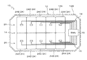
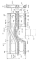
図1、図2に示すように、車両用電源装置10は、ケース12と、組電池14と、電池管理装置16と、検知用ハーネス18と、プロテクタ20とを含んで構成されている。
ケース12は、トレー12Aと、トレー12Aに係脱可能に被せられる蓋体12Bとを含んで構成されている。
組電池14と、電池管理装置16と、検知用ハーネス18と、プロテクタ20と、カバー22とは、ケース12に収容されている。
組電池14は、複数の電池モジュール24が一方向に並べられた電池モジュール列26の1つ以上で構成されており、本実施の形態では、5つの電池モジュール24からなる電池モジュール列26が2つ平行して設けられることで組電池14が構成されている。
したがって、各電池モジュール列26は、第1電池モジュール24A、第2電池モジュール24B、第3電池モジュール24C、第4電池モジュール24D、第5電池モジュール24Eの5つの電池モジュール24で構成されている。
Hereinafter, embodiments of the present invention will be described with reference to the drawings.
The vehicle power supply device of the present embodiment is mounted on an electric vehicle whose drive source is only a motor, a hybrid vehicle, or an electric vehicle whose drive source is a motor such as a plug-in hybrid vehicle.
As shown in FIGS. 1 and 2, the vehicle
The
The assembled
The assembled
Therefore, each
電池モジュール24は、モジュールケース28と、複数の電池セル30と、モジュール側コネクタ32を含んで構成されている。
モジュールケース28は、ハウジング2802と、ハウジング2802に係脱可能に被せられる蓋体2804とを含んで構成されている。
ハウジング2802は、上部および側方が開放された直方体状を呈している。
電池セル30は、長方形板状を呈し、正極端子および負極端子からなる一対の電極端子が突設された端子面3002を有している。
複数の電池セル30は、端子面3002を上方に向け、厚さ方向を水平方向に向けて並べられた状態でハウジング2802に収容され、複数の電池セル30は、隣接する電池セル30の電極端子3004を接続するバスバーなどの配線部材(不図示)を介して直列に接続されている。
したがって、電池モジュール24の上面および電池モジュール列26の上面は、複数の電池セル30の端子面3002で構成されている。
モジュール側コネクタ32は、検知用ハーネス18のハーネス側コネクタ34に接続されることで電池モジュール24の電圧を検知用ハーネス18を介して電池管理装置16に伝達するためのものである。
モジュール側コネクタ32は、複数の電池セル30のうちそれら電池セル30が並べられた方向の中間に位置する電池セル30の端子面3002に配置されている。
蓋体2804は、ハウジング2802の上部の開口を閉塞するものであり、蓋体2804には、各電池セル30の一対の電極端子3004を収容する上方に凸状の凸部2806が、電極端子3004毎に形成され、また、モジュール側コネクタ32を露出させる開口部2808が形成されている。
The
The
The
The
The plurality of
Therefore, the upper surface of the
The module-
The module-
The
電池管理装置16は、BMU(Battery Management Unit)と称されるものであり、各電池モジュール24の電圧(充電状態)などの電池モジュール24の状態を示す情報を検知用ハーネス18を介して検出し、その検出結果を上位のECUに伝達するものである。
The
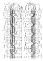
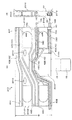
図2に示すように、プロテクタ20は、複数の検知用ハーネス18を収容し保護するものであり、プロテクタ20は、各電池モジュール列26毎に設けられている。
プロテクタ20は、電池モジュール列26の上面において、電池モジュール列26を構成する電池モジュール24が並べられた方向に延在する長さと幅W1を有している。
複数の検知用ハーネス18は、各電池モジュール列26毎に設けられ、電池モジュール列26を構成する電池モジュール24の数に対応して設けられている。
本実施の形態では、電池モジュール列26を構成する電池モジュール24は、5つ設けられることから、検知用ハーネス18は、第1検知用ハーネス18A、第2検知用ハーネス18B、第3検知用ハーネス18C、第4検知用ハーネス18D、第5検知用ハーネス18Eの5つで構成されている。
複数の検知用ハーネス18は、各電池モジュール列26毎に、プロテクタ20の長さ方向の一端2002から引き回されそれらの先端にハーネス側コネクタ34を有している。
複数の検知用ハーネス18のハーネス側コネクタ34は、電池モジュール列26を構成する各電池モジュール24のモジュール側コネクタ32に接続される。
複数の検知用ハーネス18のハーネス側コネクタ34は、プロテクタ20の幅方向の一端2004側に配置されている。
また、複数の検知用ハーネス18は、ハーネス側コネクタ34と反対側の各検知用ハーネス18の端部に、電池管理装置16と接続される電池管理装置用コネクタ36を有している。
As shown in FIG. 2, the
The
A plurality of detection harnesses 18 are provided for each
In the present embodiment, since five
The plurality of detection harnesses 18 are routed from one end 2002 in the length direction of the
The harness-
The harness-
Further, the plurality of detection harnesses 18 have a battery
プロテクタ20は、図2、図3(A)、(B)に示すように、複数の検知用ハーネス18を収容し保護すると共に、複数の検知用ハーネス18のそれぞれをそれらの長さ方向の移動を許容した状態で個別に引き回す複数のハーネス経路38を備えている。
複数のハーネス経路38は、プロテクタ20の長さ方向の一端2002において、プロテクタ20の幅W1方向の一端2004側から幅W1方向に並べられ、かつ、プロテクタ20の幅W1方向の一端2004側から幅W1方向に離れるハーネス経路38毎に、プロテクタ20の長さ方向の一端2002から次第に離れる電池モジュール24の順に検知用ハーネス18を導くように構成されている。ここで、プロテクタ20の幅W1方向の一端2004側とは、プロテクタ20の幅W1方向の一端2004を含むことは無論のこと、プロテクタ20の幅W1方向の一端2004寄りの箇所を含む意味である。
As shown in FIGS. 2, 3 (A) and 3 (B), the
The plurality of
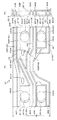
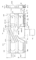
より詳細に説明すると、プロテクタ20は、図3(A)、(B)に示すように、平板状の本体板部2010と、本体板部2010の一方の面に膨出され延在形成された複数のリブ2012とを含んで構成されている。
本体板部2010には、4つの係合孔2014と、2つの取り付け用孔2016とが貫通形成されている。
4つの係合孔2014は、電池モジュール24の蓋部に形成された4つの凸部2806に係合可能に形成され、それら4つの係合孔2014が4つの凸部2806に係合されることでプロテクタ20の電池モジュール24の位置決めがなされる。
また、2つの取り付け用孔2016は、電池モジュール24の蓋体2804に設けられた2つのクリップ(不図示)に係脱可能に設けられ、それら2つの取り付け用孔2016が2つのクリップに係合することで、プロテクタ20の電池モジュール24に対する取り付けがなされる。
複数のハーネス経路38は、本体板部2010上で互いに対向する一対のリブ2012の間で形成されている。
More specifically, as shown in FIGS. 3A and 3B, the
Four engaging
The four
Further, the two mounting
The plurality of
本実施の形態では、検知用ハーネス18は、5本設けられることから、図2に示すように、ハーネス経路38は、第1ハーネス経路38A、第2ハーネス経路38B、第3ハーネス経路38C、第4ハーネス経路38D、第5ハーネス経路38Eの5つで構成されている。
第1ハーネス経路38A、第2ハーネス経路38B、第3ハーネス経路38C、第4ハーネス経路38D、第5ハーネス経路38Eは、プロテクタ20の長さ方向の一端2002において、幅W1方向の一端2004側から幅W1方向に並べられている。
また、第1ハーネス経路38A、第2ハーネス経路38B、第3ハーネス経路38C、第4ハーネス経路38D、第5ハーネス経路38Eは、プロテクタ20の長さ方向の一端2002において幅W1方向の一端2004側から幅W1方向に離れる第1ハーネス経路38A、第2ハーネス経路38B、第3ハーネス経路38C、第4ハーネス経路38D、第5ハーネス経路38E毎に、プロテクタ20の長さ方向の一端2002から次第に離れる電池モジュール24の順に検知用ハーネス18を導くように構成されている。
したがって、プロテクタ20の長さ方向の一端2002において幅W1方向の一端2004側から幅W1方向に離れる第1ハーネス経路38A、第2ハーネス経路38B、第3ハーネス経路38C、第4ハーネス経路38D、第5ハーネス経路38Eに収容される第1検知用ハーネス18A、第2検知用ハーネス18B、第3検知用ハーネス18C、第4検知用ハーネス18D、第5検知用ハーネス18E毎に、プロテクタ20の長さ方向の一端2002から次第に離れる電池モジュール24の順にハーネス側コネクタ34がモジュール側コネクタ32に接続される。
また、複数のハーネス経路38に配置される複数の検知用ハーネス18は、それらのハーネス側コネクタ34が接続される電池モジュール24に対応するプロテクタ20の箇所において固定具40(図4〜図8参照)を用いて固定されている。
In the present embodiment, five detection harnesses 18 are provided. Therefore, as shown in FIG. 2, the
The
Further, the
Therefore, at one end 2002 in the length direction of the
Further, the plurality of detection harnesses 18 arranged in the plurality of
本実施の形態では、プロテクタ20は、図2、図3、図4〜図8に示すように、電池モジュール列26を構成する5つの電池モジュール24毎に設けられた5つのプロテクタ分割体21、すなわち、第1プロテクタ分割体21A、第2プロテクタ分割体21B、第3プロテクタ分割体21C、第4プロテクタ分割体21D、第5プロテクタ分割体21Eが電池モジュール列26の長さ方向に並べられることで構成されている。
各プロテクタ分割体21は、プロテクタ20の長さよりも小さい寸法の長さと、プロテクタ20と等しい幅W1を有している。
各プロテクタ分割体21は、プロテクタ分割体21が配置される電池モジュール24の箇所に対応したハーネス経路38の部分を構成する複数のハーネス分割経路42を有している。
複数のハーネス分割経路42は、検知用ハーネス18が5本設けられることから、ハーネス分割経路42は、第1ハーネス分割経路42A、第2ハーネス分割経路42B、第3ハーネス分割経路42C、第4ハーネス分割経路42D、第5ハーネス分割経路42Eの5つで構成されている。
なお、各プロテクタ分割体21は、互いに切り離されていてもよく、あるいは、隣り合うプロテクタ分割体21同士が係脱可能に結合されるものであってもよい。
In the present embodiment, as shown in FIGS. 2, 3 and 4 to 8, the
Each protector split
Each protector split
Since the plurality of
The
プロテクタ分割体21がそれぞれ有する複数のハーネス分割経路42のうち、最も幅W1方向の一端2004側に位置する第1ハーネス分割経路42Aは、そのプロテクタ分割体21が配置される電池モジュール24に検知用ハーネス18を導くように構成されている。
図3に示すように、プロテクタ分割体21の長さ方向の一端2102側に位置する第1〜第5ハーネス分割経路42A〜42Eの箇所が、プロテクタ分割体21の幅W1方向の一端2104側から離れる順に第1経路入口44A、第2経路入口44B、第3経路入口44C、第4経路入口44D、第5経路入口44Eとなっている。
また、プロテクタ分割体21の長さ方向の他端2103側に位置する第2から第5ハーネス分割経路42B〜42Eの箇所が、プロテクタ分割体21の幅W1方向の一端2104から離れる順に第2経路出口46B、第3経路出口46C、第4経路出口46D、第5経路出口46Eとなっている。
そして、プロテクタ分割体21の幅W1方向において、第2経路出口46Bは第1経路入口44Aと、第3経路出口46Cは第2経路入口44Bと、第4経路出口46Dは第3経路入口44Cと、第5経路出口46Eは第4経路入口44Dと同じ位置に設けられている。
Of the plurality of
As shown in FIG. 3, the portions of the first to fifth
Further, the second to fifth
Then, in the width W1 direction of the protector split
すなわち、プロテクタ分割体21の幅W1方向の一端2104側から幅W1方向に離れるハーネス分割経路の順に、3以上の整数であるNを1から順に増やして複数のハーネス分割経路を第Nハーネス分割経路と表す。
図3に示すように、プロテクタ分割体21の長さ方向でプロテクタ20の長さ方向の一端2102側に位置するプロテクタ分割体21の端部を分割体一端2110とする。その反対に位置するプロテクタ分割体21の端部を分割体他端2112とする。
この場合、プロテクタ分割体21の幅W1方向の一端に配置される第1ハーネス分割経路は、プロテクタ分割体21が配置された電池モジュール24に接続用のハーネス側コネクタ34が設けられる検知用ハーネス引き回し用で分割体一端2110側が経路入口となっている。
第1ハーネス分割経路を除いた残りの第(N−1)ハーネス分割経路は、分割体一端2110側が経路入口で、分割体他端2112側が経路出口となっている。
第(N−1)分割経路の経路出口は、第(N−2)分割経路の経路入口と、プロテクタ分割体21の幅方向において同一の位置に位置している。
That is, in the order of the harness division path away from one
As shown in FIG. 3, the end portion of the protector divided
In this case, the first harness dividing path arranged at one end of the
The remaining (N-1) harness dividing path excluding the first harness dividing path has a route inlet at one
The route exit of the (N-1) divided route is located at the same position as the route entrance of the (N-2) divided route in the width direction of the protector divided
本実施の形態では、複数のプロテクタ分割体21がそれぞれ有する複数のハーネス分割経路42は、同一構造で形成されている。
すなわち、第1ハーネス分割経路42A、第2ハーネス分割経路42B、第3ハーネス分割経路42C、第4ハーネス分割経路42D、第5ハーネス分割経路42Eは、プロテクタ分割体21の幅方向における経路入口や経路出口の位置を含み、他の箇所の構成も同一の構造で形成されている。
In the present embodiment, the plurality of
That is, the first
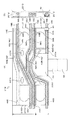
したがって、図4に示すように、第1プロテクタ分割体21Aでは、第1ハーネス分割経路42A、第2ハーネス分割経路42B、第3ハーネス分割経路42C、第4ハーネス分割経路42D、第5ハーネス分割経路42Eに、第1検知用ハーネス18A、第2検知用ハーネス18B、第3検知用ハーネス18C、第4検知用ハーネス18D、第5検知用ハーネス18Eが収容され、第1検知用ハーネス18Aのハーネス側コネクタ34が第1電池モジュール24Aのモジュール側コネクタ32に接続される。
なお、図4から図8において符号2202はカバー22の一部をなすカバー部分を示し、このカバー部分2202により各検知用ハーネス18のうちハーネス側コネクタ34に接続される部分が覆われている。
Therefore, as shown in FIG. 4, in the first
In FIGS. 4 to 8,
また、図5に示すように、第2プロテクタ分割体21Bでは、第1ハーネス分割経路42A、第2ハーネス分割経路42B、第3ハーネス分割経路42C、第4ハーネス分割経路42Dに、第2検知用ハーネス18B、第3検知用ハーネス18C、第4検知用ハーネス18D、第5検知用ハーネス18Eが収容され、第2検知用ハーネス18Bのハーネス側コネクタ34が第2電池モジュール24Bのモジュール側コネクタ32に接続される。
Further, as shown in FIG. 5, in the second
また、図6に示すように、第3プロテクタ分割体21Cでは、第1ハーネス分割経路42A、第2ハーネス分割経路42B、第3ハーネス分割経路42Cに、第3検知用ハーネス18C、第4検知用ハーネス18D、第5検知用ハーネス18Eが収容され、第3検知用ハーネス18Cのハーネス側コネクタ34が第3電池モジュール24Cのモジュール側コネクタ32に接続される。
Further, as shown in FIG. 6, in the third
また、図7に示すように、第4プロテクタ分割体21Dでは、第1ハーネス分割経路42A、第2ハーネス分割経路42Bに、第4検知用ハーネス18D、第5検知用ハーネス18Eが収容され、第4検知用ハーネス18Dのハーネス側コネクタ34が第4電池モジュール24Dのモジュール側コネクタ32に接続される。
Further, as shown in FIG. 7, in the fourth protector split
また、図8に示すように、第5プロテクタ分割体21Eでは、第1ハーネス分割経路42Aに、第5検知用ハーネス18Eが収容され、第5検知用ハーネス18Eのハーネス側コネクタ34が第5電池モジュール24Eのモジュール側コネクタ32に接続される。
Further, as shown in FIG. 8, in the fifth protector split
本実施の形態では、プロテクタ20にカバー22が設けられ、図4から図8に示すように、各プロテクタ分割体21にそれぞれ複数の検知用ハーネス18が収容された状態でカバー22が被されることで、検知用ハーネス18がハーネス分割経路42から上方に外れることを抑制し、また、検知用ハーネス18の保護が図られている。
なお、本実施の形態では、互いに対向するリブ2012によりハーネス経路38が形成されている場合について説明したが、ハーネス経路38の形状は任意であり、従来公知の様々なプロテクタ20の構造が採用可能であり、また、カバー22が用いられるか否かは任意である。
In the present embodiment, the
In the present embodiment, the case where the
次に本実施の形態の作用効果について説明する。
複数のハーネス経路38は、プロテクタ20の長さ方向の一端2002においてプロテクタ20の幅W1方向の一端2004側から幅W1方向に並べられ、かつ、プロテクタ20の長さ方向の一端2002において、プロテクタ20の幅W1方向の一端2004側から幅W1の他端方向に離れるハーネス経路38毎に、プロテクタ20の長さ方向の一端2002から次第に離れる電池モジュール24の順に検知用ハーネス18を導くように構成されている。
また、プロテクタ20の幅W1方向の一端2004には、第1〜第5検知用ハーネス18A〜18Eのハーネス側コネクタ34が配置されている。
したがって、各ハーネス経路38毎に沿って検知用ハーネス18を1つずつ引き回すことで無駄な余長が必要無くなる。そのため、第1〜第5検知用ハーネス18A〜18Eが単一のハーネス経路に沿って配置され、この単一のハーネス経路から各電池モジュール24毎に枝分かれして電池モジュール24に引き回される場合に比べて第1〜第5検知用ハーネス18A〜18Eの長さを短縮でき、第1〜第5検知用ハーネス18A〜18Eの長さの総和を短縮化する上で有利となり、車両用電源装置10のコストダウンを図る上で有利となる。
また、各検知用ハーネス18が1つずつハーネス経路38に沿って引き回されていることから、各検知用ハーネス18はその長さ方向の動きがある程度規制されている。したがって、検知用ハーネス18の位置ずれ防止用の固定具40の設置数を最小限に抑えることができるので、衝撃入力時に固定具40が取り付けられている検知用ハーネス18の部分で電線破断が生じることを抑制する上で有利となる。
Next, the action and effect of this embodiment will be described.
The plurality of
Further, harness-
Therefore, by routing the
Further, since each
また、本実施の形態では、複数のハーネス経路38に配置される複数の検知用ハーネス18は、それらのハーネス側コネクタ34が接続される電池モジュール24に対応するプロテクタ20の箇所において固定されている。
したがって、車両衝突時などのように電池モジュール24に荷重が加わり、電池モジュール24が移動した場合、移動した電池モジュール24のプロテクタ20も移動する。そして、移動したプロテクタ20に固定された検知用ハーネス18に引張力が作用すると、その引張力が作用した検知用ハーネス18は、その検知用ハーネス18が収容されたハーネス経路38に沿って移動しようとする。
この場合、予め、複数の検知用ハーネス18がプロテクタ20に導入される手前の箇所において、複数の検知用ハーネス18の全てについてたるませ、余長を確保しておけば、引張力が作用した検知用ハーネス18の移動がそれぞれ個別に許容され、引張力が作用した検知用ハーネス18に加わる荷重を軽減でき、検知用ハーネス18、ハーネス側コネクタ34、モジュール側コネクタ32の損傷を抑制する上で有利となる。
例えば、第3プロテクタ分割体21Cでは、第1プロテクタ分割体21Aおよび第2プロテクタ分割体21Bに引き回された第3検知用ハーネス18Cの部分と、第1プロテクタ分割体21Aの第3経路入口44Cから外側の第3検知用ハーネス18Cの部分とにより余長を大きく確保でき、これにより引張力が作用した第3検知用ハーネス18Cに加わる荷重を軽減でき、第3検知用ハーネス18C、ハーネス側コネクタ34、モジュール側コネクタ32の損傷を抑制する上で有利となる。
Further, in the present embodiment, the plurality of detection harnesses 18 arranged in the plurality of
Therefore, when a load is applied to the
In this case, if all of the plurality of detection harnesses 18 are slackened in advance at a position before the plurality of detection harnesses 18 are introduced into the
For example, in the
また、本実施の形態では、プロテクタ20は、電池モジュール列26を構成する電池モジュール24毎に設けられた複数のプロテクタ分割体21A〜21Eが電池モジュール列26の長さ方向に並べられることで構成され、各プロテクタ分割体21A〜21Eは、プロテクタ分割体21A〜21Eが配置される電池モジュール24の箇所に対応したハーネス経路38の部分を構成する複数のハーネス分割経路42A〜42Eを有している。
したがって、電池モジュール列26を構成する電池モジュール24の数が増減し、検知用ハーネス18の数が増減した場合、プロテクタ分割体21を増減することでプロテクタ20を簡単に構成することができるため、車両用電源装置10の仕様変更に柔軟に対応する上で有利となり、かつ、プロテクタ20を設計し直す必要がないためコストの抑制を図る上でも有利となる。
Further, in the present embodiment, the
Therefore, when the number of
また、プロテクタ分割体21の幅W1方向の一端に配置される第1ハーネス分割経路は、プロテクタ分割体21が配置された電池モジュール24に接続用のハーネス側コネクタ34が設けられる検知用ハーネス引き回し用で分割体一端2110側が経路入口となっており、第1ハーネス分割経路を除いた残りの第(N−1)ハーネス分割経路は、分割体一端2110側が経路入口で、分割体他端2112側が経路出口となっており、第(N−1)分割経路の経路出口は、第(N−2)分割経路の経路入口と、プロテクタ分割体21の幅方向において同一の位置に位置している。
そのため、経路入口と経路出口とを以上のような位置関係を満たすプロテクタ分割体21の複数によりプロテクタ20を簡単に構成でき、プロテクタ20の部品コストを低減する上で有利となる。
Further, the first harness dividing path arranged at one end of the
Therefore, the
なお、本発明において、一端2002から離れる電池モジュール24毎にハーネス分割経路42の数を次第に減らし、また、プロテクタ分割体の幅を次第に小さくしたプロテクタ分割体を用いても良いが、本実施の形態のように、複数のプロテクタ分割体21A〜21Eがそれぞれ有する複数のハーネス分割経路42A〜42Eを、プロテクタ分割体21の幅方向における経路入口や経路出口の位置を含み、他の箇所の構成も同一の構造で形成すると、同一のプロテクタ分割体21を並べるだけでプロテクタ20を構成できるため、複数種類のプロテクタ分割体21でプロテクタ20を構成する場合に比較してプロテクタ20の部品コストを低減する上で有利となる。
また、プロテクタ分割体21に設けるハーネス分割経路の数を多めに形成しておくと、電池モジュール列26を構成する電池モジュール24の数が増減し、検知用ハーネス18の数が増減した場合など、プロテクタ分割体21を増減することで車両用電源装置10の仕様変更に柔軟に対応する上で有利となり、かつ、プロテクタ分割体21を設計し直す必要がないためコストの抑制を図る上でも有利となる。
In the present invention, the number of
Further, if the number of harness division paths provided in the
10 車両用電源装置
14 組電池
16 電池管理装置
18 検知用ハーネス
20 プロテクタ
2002 プロテクタの長さ方向の一端
2004 プロテクタの幅方向の一端
21 分割体
21A〜21E 第1〜第5プロテクタ分割体
24 電池モジュール
24A〜24E 第1〜第5電池モジュール
26 電池モジュール列
32 モジュールコネクタ
34 ハーネス側コネクタ
38 ハーネス経路
38A〜38E 第1〜第5ハーネス経路
40 固定具
42A〜42E 第1〜第5ハーネス分割経路
44A〜44E 第1〜第5経路入口
46A〜46E 第1〜第5経路出口
W1 幅
10
Claims (6)
前記電池モジュール列にまたは前記各電池モジュール列毎に設けられ前記電池モジュール列の長さ方向に延在する長さと、この長さと直交する方向の幅とを有するプロテクタと、
前記プロテクタの長さ方向の一端から引き回されそれらの先端に前記電池モジュール列を構成する前記各電池モジュールと接続されるハーネス側コネクタを有する複数の検知用ハーネスとを備え、
前記各ハーネス側コネクタは、前記電池モジュール列を構成する前記各電池モジュールに対応した箇所で前記プロテクタの幅方向の一端側に配置される車両用電源装置であって、
前記プロテクタは、前記電池モジュール列を構成する電池モジュール毎に設けられた複数のプロテクタ分割体が前記電池モジュール列の長さ方向に並べられることで構成されるとともに、前記複数の検知用ハーネスのそれぞれをそれらの長さ方向の移動を許容した状態で個別に引き回す複数のハーネス経路を備え、
前記複数のハーネス経路は、前記プロテクタに形成された複数のリブによってそれぞれ独立し、前記プロテクタの長さ方向の前記一端において前記プロテクタの幅方向の前記一端側から前記幅方向に並べられ、かつ、前記プロテクタの幅方向の前記一端側から前記幅方向に離れる前記ハーネス経路毎に、前記プロテクタの長さ方向の前記一端から次第に離れる前記電池モジュールの順に前記検知用ハーネスを導くように構成されている、
ことを特徴とする車両用電源装置。 With one or more battery module rows in which multiple battery modules are arranged in one direction,
A protector provided in the battery module row or for each battery module row and having a length extending in the length direction of the battery module row and a width in a direction orthogonal to this length.
A plurality of detection harnesses having a harness-side connector connected to each battery module forming the battery module row are provided at the tip thereof, which is routed from one end in the length direction of the protector.
Each harness-side connector is a vehicle power supply device arranged on one end side in the width direction of the protector at a position corresponding to each battery module constituting the battery module row.
The protector is configured by arranging a plurality of protector divisions provided for each battery module constituting the battery module row in the length direction of the battery module row, and each of the plurality of detection harnesses. Equipped with multiple harness paths that are individually routed while allowing their longitudinal movement,
The plurality of harness paths are independent of each other by a plurality of ribs formed on the protector, and are arranged in the width direction from the one end side in the width direction of the protector at the one end in the length direction of the protector. The detection harness is configured to guide the detection harness in the order of the battery module gradually separated from the one end in the length direction of the protector for each of the harness paths separated from the one end side in the width direction of the protector in the width direction. ,
A vehicle power supply that is characterized by this.
ことを特徴とする請求項1に記載の車両用電源装置。The vehicle power supply device according to claim 1.
ことを特徴とする請求項1または2に記載の車両用電源装置。The vehicle power supply device according to claim 1 or 2.
ことを特徴とする請求項1〜3の何れかに記載の車両用電源装置。 The plurality of detection harnesses are fixed at the position of the protector corresponding to the battery module to which the harness side connectors are connected.
The vehicle power supply device according to any one of claims 1 to 3 .
前記プロテクタ分割体の幅方向の一端側から前記幅方向に離れる前記ハーネス分割経路の順に、3以上の整数であるNを1から順に増やして前記複数のハーネス分割経路を第Nハーネス分割経路と表し、前記プロテクタ分割体の長さ方向で前記プロテクタの長さ方向の前記一端側に位置する前記プロテクタ分割体の端部を分割体一端とし、その反対に位置する前記プロテクタ分割体の端部を分割体他端とした場合、
前記プロテクタ分割体の幅方向の一端側に配置される第1ハーネス分割経路は、前記プロテクタ分割体が配置された前記電池モジュールに接続用のハーネス側コネクタが設けられる検知用ハーネス引き回し用で前記分割体一端側が経路入口となっており、
前記第1ハーネス分割経路を除いた残りの第(N−1)ハーネス分割経路は、前記分割体一端側が経路入口で、前記分割体他端側が経路出口となっており、
第(N−1)ハーネス分割経路の経路出口は、第(N−2)ハーネス分割経路の経路入口と、前記プロテクタ分割体の幅方向において同一の位置に位置している、
ことを特徴とする請求項1〜4の何れかに記載の車両用電源装置。 Each protector split body has a plurality of harness split paths constituting a portion of the harness path corresponding to the location of the battery module in which the protector split body is arranged, and has a length smaller than the length of the protector. And the width is equal to the width of the protector.
The plurality of harness division paths are represented as the Nth harness division path by increasing N, which is an integer of 3 or more, in order from one end side of the protector division body in the width direction to the harness division path away from the width direction. The end of the protector split body located on the one end side in the length direction of the protector in the length direction of the protector split body is set as one end of the split body, and the end portion of the protector split body located on the opposite side is divided. When the other end of the body
The first harness dividing path arranged on one end side in the width direction of the protector dividing body is for routing a detection harness in which a harness side connector for connection is provided to the battery module in which the protector dividing body is arranged. One end of the body is the entrance to the route,
The remaining (N-1) harness dividing path excluding the first harness dividing path has a path inlet on one end side of the divided body and a path exit on the other end side of the divided body.
Path outlet of the (N-1) Harness division path, and the path inlet of the (N-2) harness divisional path, are located at the same position in the width direction of the protector split body,
The vehicle power supply device according to any one of claims 1 to 4 .
ことを特徴とする請求項5に記載の車両用電源装置。 Of the plurality of protector split bodies, at least a pair of the protector split bodies have the same structure as the plurality of harness split paths formed in each of the plurality of protector split bodies.
The vehicle power supply device according to claim 5 .
Priority Applications (1)
| Application Number | Priority Date | Filing Date | Title |
|---|---|---|---|
| JP2016226528A JP6779110B2 (en) | 2016-11-22 | 2016-11-22 | Vehicle power supply |
Applications Claiming Priority (1)
| Application Number | Priority Date | Filing Date | Title |
|---|---|---|---|
| JP2016226528A JP6779110B2 (en) | 2016-11-22 | 2016-11-22 | Vehicle power supply |
Publications (2)
| Publication Number | Publication Date |
|---|---|
| JP2018085191A JP2018085191A (en) | 2018-05-31 |
| JP6779110B2 true JP6779110B2 (en) | 2020-11-04 |
Family
ID=62237221
Family Applications (1)
| Application Number | Title | Priority Date | Filing Date |
|---|---|---|---|
| JP2016226528A Active JP6779110B2 (en) | 2016-11-22 | 2016-11-22 | Vehicle power supply |
Country Status (1)
| Country | Link |
|---|---|
| JP (1) | JP6779110B2 (en) |
Families Citing this family (2)
| Publication number | Priority date | Publication date | Assignee | Title |
|---|---|---|---|---|
| KR102903026B1 (en) * | 2020-11-09 | 2025-12-19 | 주식회사 엘지에너지솔루션 | Battery pack and Vehicle comprising the same |
| CN217145708U (en) * | 2022-04-07 | 2022-08-09 | 时代电服科技有限公司 | Battery bin of battery replacing system and battery replacing system |
Family Cites Families (6)
| Publication number | Priority date | Publication date | Assignee | Title |
|---|---|---|---|---|
| JPH1070842A (en) * | 1996-08-27 | 1998-03-10 | Matsushita Electric Ind Co Ltd | Power supply |
| JP3485162B2 (en) * | 1998-10-09 | 2004-01-13 | 矢崎総業株式会社 | Battery connection plate and method of manufacturing the same |
| JP5506307B2 (en) * | 2009-09-24 | 2014-05-28 | 矢崎総業株式会社 | Electric wire routing device |
| JP2011091003A (en) * | 2009-10-26 | 2011-05-06 | Autonetworks Technologies Ltd | Battery connection assembly |
| JP6125311B2 (en) * | 2013-04-26 | 2017-05-10 | 矢崎総業株式会社 | Bus bar module and power supply |
| JP6696402B2 (en) * | 2016-10-21 | 2020-05-20 | 三菱自動車工業株式会社 | Protector for harness of electric vehicle |
-
2016
- 2016-11-22 JP JP2016226528A patent/JP6779110B2/en active Active
Also Published As
| Publication number | Publication date |
|---|---|
| JP2018085191A (en) | 2018-05-31 |
Similar Documents
| Publication | Publication Date | Title |
|---|---|---|
| US8603661B2 (en) | Battery connection plate | |
| JP6220547B2 (en) | Bus bar module | |
| JP5779010B2 (en) | Bus bar module structure | |
| JP5992694B2 (en) | Electric wire routing device | |
| CN112103460A (en) | Bus bar module | |
| JP6202338B2 (en) | Wiring module, wiring module intermediate, and wiring module manufacturing method | |
| WO2011108513A1 (en) | Battery connection assembly | |
| JP6597440B2 (en) | Battery pack | |
| CN104810499A (en) | Vehicle traction battery assembly and methods for assembling vehicle traction battery | |
| JP7256079B2 (en) | Electric wire holding structure and busbar module | |
| JPWO2017179650A1 (en) | Power storage device | |
| CN112002866B (en) | Battery Wiring Module | |
| CN107615519B (en) | Electricity storage module | |
| US10483516B2 (en) | Electricity storage module and electricity storage pack | |
| JP6779110B2 (en) | Vehicle power supply | |
| EP4145602B1 (en) | Battery pack and automobile comprising same | |
| JP7099310B2 (en) | Vehicle-mounted structure of power storage device | |
| WO2021006000A1 (en) | Connection module | |
| CN110534685B (en) | Connection module | |
| US12142791B2 (en) | Bus bar module | |
| JP7077295B2 (en) | Bus bar module | |
| JP6820896B2 (en) | Battery unit | |
| JP5606105B2 (en) | Wiring harness wiring structure | |
| WO2021131861A1 (en) | Battery wiring module | |
| JP2025073712A (en) | Battery pack |
Legal Events
| Date | Code | Title | Description |
|---|---|---|---|
| A621 | Written request for application examination |
Free format text: JAPANESE INTERMEDIATE CODE: A621 Effective date: 20190514 |
|
| A131 | Notification of reasons for refusal |
Free format text: JAPANESE INTERMEDIATE CODE: A131 Effective date: 20200303 |
|
| A977 | Report on retrieval |
Free format text: JAPANESE INTERMEDIATE CODE: A971007 Effective date: 20200228 |
|
| A521 | Request for written amendment filed |
Free format text: JAPANESE INTERMEDIATE CODE: A523 Effective date: 20200423 |
|
| A521 | Request for written amendment filed |
Free format text: JAPANESE INTERMEDIATE CODE: A523 Effective date: 20200526 |
|
| TRDD | Decision of grant or rejection written | ||
| A01 | Written decision to grant a patent or to grant a registration (utility model) |
Free format text: JAPANESE INTERMEDIATE CODE: A01 Effective date: 20200929 |
|
| A61 | First payment of annual fees (during grant procedure) |
Free format text: JAPANESE INTERMEDIATE CODE: A61 Effective date: 20201013 |
|
| R150 | Certificate of patent or registration of utility model |
Ref document number: 6779110 Country of ref document: JP Free format text: JAPANESE INTERMEDIATE CODE: R150 |
|
| R250 | Receipt of annual fees |
Free format text: JAPANESE INTERMEDIATE CODE: R250 |
|
| R250 | Receipt of annual fees |
Free format text: JAPANESE INTERMEDIATE CODE: R250 |