JP6778044B2 - Target pole and surveying system - Google Patents
Target pole and surveying system Download PDFInfo
- Publication number
- JP6778044B2 JP6778044B2 JP2016154523A JP2016154523A JP6778044B2 JP 6778044 B2 JP6778044 B2 JP 6778044B2 JP 2016154523 A JP2016154523 A JP 2016154523A JP 2016154523 A JP2016154523 A JP 2016154523A JP 6778044 B2 JP6778044 B2 JP 6778044B2
- Authority
- JP
- Japan
- Prior art keywords
- pole
- target
- axis
- offset plate
- holder
- Prior art date
- Legal status (The legal status is an assumption and is not a legal conclusion. Google has not performed a legal analysis and makes no representation as to the accuracy of the status listed.)
- Active
Links
Images


Description
本発明は、測量装置によりプリズム測定を行う為のターゲットポール及び該ターゲットポールを用いた測量システムに関するものである。 The present invention relates to a target pole for performing prism measurement by a surveying device and a surveying system using the target pole.
プリズムには、測定点を示すターゲットポールが用いられる。ターゲットポールは、下端が石突きとなっているポール、該ポールに設けられるプリズムや反射シート等再帰反射体のターゲットを有する。プリズム測定を行う際には、ポールの石突きを測定点上に立て、測量装置によりターゲットを測定することで、測定点の3次元座標を測定している。 A target pole indicating a measurement point is used for the prism. The target pole has a pole having a ridge at the lower end, and a target of a retroreflective body such as a prism or a reflective sheet provided on the pole. When performing prism measurement, the three-dimensional coordinates of the measurement point are measured by standing the pole butt on the measurement point and measuring the target with a surveying device.
ターゲットとしては、1素子のコーナキューブプリズムが用いられることがある。プリズムの場合、見かけ上の光学的な中心(以下、浮上点と称す)がプリズムの内部にある為、ポールにプリズムを取付けたターゲットポールの場合、測定点の鉛直上に浮上点が存在しない。 As the target, a one-element corner cube prism may be used. In the case of a prism, since the apparent optical center (hereinafter referred to as a levitation point) is inside the prism, in the case of a target pole in which a prism is attached to a pole, there is no levitation point vertically above the measurement point.
従って、測定点上にポールを鉛直に立てたとしても、プリズムを測量装置と正対させた場合と正対させていない場合とで、自動視準の際に角度誤差を生じ、測定結果にも誤差を生じていた。 Therefore, even if the pole is erected vertically on the measurement point, an angle error will occur during automatic collimation depending on whether the prism faces the surveying device or not, and the measurement result also shows. There was an error.
又、特許文献1に示される様に、測量装置にプリズムを正対させた場合、正対させていない場合に生じる角度誤差、測定誤差を防止する為、ポールの軸心上に浮上点が位置する様、ポールの中途部にプリズムを設けたターゲットポールもある。
Further, as shown in
上記のターゲットポールの場合、ポールが浮上点を中心に回転する為、プリズムが測量装置に正対しているかどうかに拘わらず、自動視準の際の角度誤差、測定結果の誤差は生じない。然し乍ら、プリズムによりポールが上下に分断される構成となる為、プリズムの高さを変える際には、ポールの交換や追加等が必要となっていた。 In the case of the above target pole, since the pole rotates about the levitation point, no angle error or measurement result error occurs during automatic collimation regardless of whether the prism faces the surveying device. However, since the pole is divided into upper and lower parts by the prism, it is necessary to replace or add the pole when changing the height of the prism.
尚、プリズムを測量装置に正対させる為のものとして、特許文献2に示される反射プリズム等の正対装置がある。
As a device for making the prism face the surveying device, there is a facing device such as a reflection prism shown in
本発明は、容易にターゲットの高さ調整が可能であり、ターゲットの向きに拘わらず浮上点の位置を一定とするターゲットポール及び測量システムを提供するものである。 The present invention provides a target pole and a surveying system in which the height of a target can be easily adjusted and the position of a floating point is constant regardless of the orientation of the target.
本発明は、再帰反射体のターゲットを保持するターゲットホルダと、該ターゲットホルダが摺動自在に設けられたポールと、該ポールが取付けられたオフセット板と、該オフセット板に下方に突出する様取付けられた石突きとを具備し、前記ターゲットの光学中心が前記石突きの軸心上に位置する様構成されたターゲットポールに係るものである。 In the present invention, a target holder for holding a target of a retroreflector, a pole on which the target holder is slidably provided, an offset plate to which the pole is attached, and attachment so as to project downward to the offset plate. It relates to a target pole having a provided stab and configured such that the optical center of the target is located on the axis of the stab.
又本発明は、前記ポールは円柱状であり、前記ターゲットホルダの上面に第1位置合せラインが形成され、前記ポールの周面に該ポールの軸心と平行な第2位置合せラインが形成され、前記第1位置合せラインと前記第2位置合せラインとが合致する位置で、前記光学中心が前記石突きの軸心上に位置するターゲットポールに係るものである。 Further, in the present invention, the pole is cylindrical, a first alignment line is formed on the upper surface of the target holder, and a second alignment line parallel to the axis of the pole is formed on the peripheral surface of the pole. It relates to a target pole whose optical center is located on the axis of the stone tip at a position where the first alignment line and the second alignment line meet.
又本発明は、前記ポールは円柱状であり、該ポールの軸心と平行に位置合せ溝が形成され、前記ターゲットホルダは前記位置合せ溝に嵌合可能なロックネジを有し、該ロックネジと前記位置合せ溝との嵌合で、前記光学中心が前記石突きの軸心に合致するターゲットポールに係るものである。 Further, in the present invention, the pole is cylindrical, an alignment groove is formed parallel to the axis of the pole, the target holder has a lock screw that can be fitted into the alignment groove, and the lock screw and the above. It relates to a target pole whose optical center coincides with the axis of the ridge when fitted with the alignment groove.
又本発明は、前記ポールは多角柱状であるターゲットポールに係るものである。 Further, the present invention relates to a target pole in which the pole is a polygonal columnar shape.
又本発明は、前記ターゲットは、前記石突きの軸心に直交し、前記光学中心を通過する軸心を中心に回転可能に設けられたターゲットポールに係るものである。 Further, the present invention relates to a target pole that is orthogonal to the axis of the stone tip and is rotatably provided about the axis passing through the optical center.
又本発明は、前記ターゲットホルダは、前記ターゲットを保持する保持部と、前記ポールに摺動自在に設けられたスライド部とで構成され、前記保持部は前記スライド部に対して前記石突きの軸心と直交し、前記光学中心を通過する水平軸心を中心に回転可能であるターゲットポールに係るものである。 Further, in the present invention, the target holder is composed of a holding portion for holding the target and a slide portion slidably provided on the pole, and the holding portion is formed by the stone tip with respect to the slide portion. It relates to a target pole that is orthogonal to the axis and is rotatable about a horizontal axis that passes through the optical center.
又本発明は、前記ターゲットは、前記水平軸心と直交し、前記光学中心を通過する軸心を中心に回転可能に前記保持部に設けられたターゲットポールに係るものである。 Further, the present invention relates to a target pole provided in the holding portion so that the target is orthogonal to the horizontal axis and can rotate around the axis passing through the optical center.
又本発明は、前記オフセット板にはポール挿入孔が穿設され、該ポール挿入孔に前記ポールを挿脱可能としたターゲットポールに係るものである。 The present invention also relates to a target pole in which a pole insertion hole is formed in the offset plate so that the pole can be inserted and removed from the pole insertion hole.
又本発明は、前記オフセット板には、前記石突きの軸心との距離がそれぞれ異なる複数のポール挿入孔が穿設され、該ポール挿入孔に前記ポールを挿脱可能としたターゲットポールに係るものである。 The present invention also relates to a target pole in which a plurality of pole insertion holes having different distances from the axis of the stone tip are formed in the offset plate, and the pole can be inserted and removed in the pole insertion hole. It is a thing.
又本発明は、前記ターゲットは、1素子プリズム又は反射シートであるターゲットポールに係るものである。 Further, in the present invention, the target relates to a target pole which is a one-element prism or a reflective sheet.
更に又本発明は、測定点に立てられたターゲットポールに対してプリズム測定を行う測量システムであって、測量装置は水平回転可能な測量装置本体と、該測量装置本体に鉛直回転可能に設けられた望遠鏡部と、該望遠鏡部に収納され、測距光を発し、ターゲットからの反射測距光を受光して測距を行う測距部と、前記測量装置本体の水平角を検出する水平角検出器と、前記望遠鏡部の鉛直角を検出する鉛直角検出器とを有し、前記ターゲットポールは前記ターゲットを保持するターゲットホルダと、該ターゲットホルダを摺動自在に支持するポールと、該ポールが取付けられるオフセット板と、該オフセット板の下面から下方に突出する石突きとを有し、前記ターゲットの光学中心が前記石突きの軸心上に位置する測量システムに係るものである。 Furthermore, the present invention is a surveying system that performs prism measurement on a target pole set up at a measurement point, and the surveying device is provided with a surveying device main body that can rotate horizontally and a surveying device main body that can rotate vertically. The telescope unit, the distance measuring unit that is housed in the telescope unit, emits distance measuring light, receives the reflected distance measuring light from the target to perform distance measurement, and the horizontal angle that detects the horizontal angle of the surveying apparatus main body. It has a detector and a vertical angle detector that detects the vertical angle of the telescope unit, and the target pole includes a target holder that holds the target, a pole that slidably supports the target holder, and the pole. The present invention relates to a surveying system having an offset plate to which a plumb bob is attached and a plumb bob protruding downward from the lower surface of the offset plate, and the optical center of the target is located on the axis of the plumb bob.
本発明によれば、再帰反射体のターゲットを保持するターゲットホルダと、該ターゲットホルダが摺動自在に設けられたポールと、該ポールが取付けられたオフセット板と、該オフセット板に下方に突出する様取付けられた石突きとを具備し、前記ターゲットの光学中心が前記石突きの軸心上に位置する様構成されたので、前記石突きの軸心を中心に回転させた場合でも浮上点の位置は一定であり、又前記ターゲットホルダを摺動させて容易に前記ターゲットの高さを調整することができる。 According to the present invention, a target holder for holding a target of a retroreflector, a pole on which the target holder is slidably provided, an offset plate to which the pole is attached, and a downward protrusion on the offset plate. Since the target is provided with a stab mounted in such a manner and the optical center of the target is located on the axis of the stab, the levitation point can be rotated even when the stab is rotated about the axis of the stab. The position is constant, and the height of the target can be easily adjusted by sliding the target holder.
又本発明によれば、測定点に立てられたターゲットポールに対してプリズム測定を行う測量システムであって、測量装置は水平回転可能な測量装置本体と、該測量装置本体に鉛直回転可能に設けられた望遠鏡部と、該望遠鏡部に収納され、測距光を発し、ターゲットからの反射測距光を受光して測距を行う測距部と、前記測量装置本体の水平角を検出する水平角検出器と、前記望遠鏡部の鉛直角を検出する鉛直角検出器とを有し、前記ターゲットポールは前記ターゲットを保持するターゲットホルダと、該ターゲットホルダを摺動自在に支持するポールと、該ポールが取付けられるオフセット板と、該オフセット板の下面から下方に突出する石突きとを有し、前記ターゲットの光学中心が前記石突きの軸心上に位置するので、前記石突きの軸心を中心に回転させた場合でも前記光学中心の位置は一定であり、前記ターゲットが前記測量装置に正対していない場合でも、角度誤差、測定誤差を生じないことから、前記ターゲットは概略で前記測量装置に向けるだけでよく、作業性の向上を図ることができるという優れた効果を発揮する。 Further, according to the present invention, it is a surveying system that performs prism measurement on a target pole set up at a measurement point, and the surveying device is provided with a surveying device main body that can rotate horizontally and a surveying device main body that can rotate vertically. The telescope unit, the distance measuring unit that is housed in the telescope unit, emits distance measuring light, receives the reflected distance measuring light from the target to perform distance measurement, and the horizontal that detects the horizontal angle of the surveying device main body. It has an angle detector and a vertical angle detector that detects the vertical angle of the telescope unit, and the target pole includes a target holder that holds the target, a pole that slidably supports the target holder, and the like. Since it has an offset plate to which a pole is attached and a plumb bob protruding downward from the lower surface of the offset plate, and the optical center of the target is located on the axis of the surveying, the axis of the surveying can be set. Since the position of the optical center is constant even when rotated to the center and no angle error or measurement error occurs even when the target does not face the surveying device, the target is roughly the surveying device. It has an excellent effect that workability can be improved by simply turning it toward.
以下、図面を参照しつつ本発明の実施例を説明する。 Hereinafter, examples of the present invention will be described with reference to the drawings.
先ず、図1に於いて、本発明の第1の実施例に係るターゲットポール1について説明する。
First, in FIG. 1, the
例えば1素子のプリズムであるターゲット2がターゲットホルダ3に保持されている。該ターゲットホルダ3には、円柱状のポール4が貫通しており、前記ターゲットホルダ3は前記ポール4に対して摺動自在となっている。
For example, the
又、前記ターゲットホルダ3にはロックネジ5が螺入され、該ロックネジ5を締込み前記ポール4に押圧させることで、前記ターゲットホルダ3が所望の高さで前記ポール4に支持される様になっている。
Further, a
更に、前記ターゲットホルダ3の上面には気泡管6が設けられ、該気泡管6により前記ターゲットホルダ3の水平、即ち前記ターゲット2の光軸の水平を検出することができる。前記ターゲットホルダ3が水平となった際には、前記ポール4が鉛直となる様に該ポール4と前記ターゲット2との関係が設定されている。
Further, a
前記ポール4の下端には、オフセット板7がネジ止め等所要の手段で固着されている。該オフセット板7は、前記ポール4の軸心と直交し、前記オフセット板7からは石突き8が下方に突設されている。
An offset
該石突き8は、下端部がテーパ形状で下端が突端となっている。又、該石突き8は、前記オフセット板7の下面に垂直で、前記ポール4の軸心と平行な軸心を有している。又、前記石突き8の軸心上には、前記ターゲット2の見かけ上の光学中心(以下、浮上点9と称す)が位置している。
The bottom end of the
即ち、前記ターゲット2と前記ポール4は、前記オフセット板7により、前記ポール4と前記浮上点9との距離dだけ前記石突き8からオフセットされている。
That is, the
尚、前記ポール4には、目盛り等が設けられてもよい。目盛りを設けることで該ポール4に対する前記ターゲット2の位置が確認できる。従って、前記石突き8の先端(該石突き8が立てられた測定点11)に対する前記浮上点9の鉛直方向の位置を既知とすることができる。
The
前記ターゲットポール1を設置する際には、先ず前記ロックネジ5を緩め、前記ターゲットホルダ3をスライドさせて前記ターゲット2の高さを調整する。次に、所定の前記測定点11上に前記石突き8を立て、前記気泡管6が水平を検出する様前記ポール4の傾きを調整する。
When installing the
前記気泡管6の水平検出時には、前記ポール4と前記石突き8の軸心が鉛直となる。又、前記浮上点9が前記石突き8の軸心上に位置しているので、前記浮上点9は前記測定点11の鉛直上方に位置する。従って、前記石突き8を中心とした回転は、前記浮上点9を中心とした回転となるので、前記ターゲットポール1を水平回転させても前記浮上点9の位置は変化しない。
At the time of horizontal detection of the
次に、図2に於いて、前記ターゲットポール1を用いた測量システムについて説明する。
Next, in FIG. 2, a surveying system using the
図2中、12はトータルステーション等の測量装置を示している。該測量装置12は、測量装置本体13、水平回動部14を有し、三脚15等の支持装置を介して既知の点に設置される。
In FIG. 2,
前記水平回動部14は水平回動モータ(図示せず)を有し、鉛直軸心を中心に、前記測量装置本体13を水平方向に360°全周回転させることが可能となっている。該測量装置本体13の回転量、即ち水平角は水平角検出器(図示せず)によって検出される。
The
又、前記測量装置本体13は、測定結果や測定の進行状態等を表示する表示部16と、測定条件の設定や測定結果の表示操作等を行う操作部17を有している。尚、前記表示部16は、タッチパネルとして表示部と操作部とを兼用させてもよい。
Further, the surveying device
前記測量装置本体13は望遠鏡部18を有し、該望遠鏡部18は托架部19に支持されている。前記望遠鏡部18は、水平軸心を中心に、鉛直回動モータ(図示せず)を有する鉛直回動部(図示せず)により鉛直方向に回転される。前記望遠鏡部18の回転量、即ち鉛直角は鉛直角検出器(図示せず)によって検出される。尚、前記水平回動部14と前記鉛直回動部により、前記望遠鏡部18を水平方向及び鉛直方向に回転させる駆動部が構成される。
The surveying device
前記望遠鏡部18は、視準望遠鏡(図示せず)と測距部(図示せず)とを備えている。前記視準望遠鏡は5°程度の視野角を有し、前記ターゲット2を視準可能となっている。又、前記測距部は測距光を発し、前記ターゲット2で反射された反射測距光を受光することで、該ターゲット2を測距可能となっている。
The
尚、視準光軸21と測距光軸22とは同軸となっている。又、前記望遠鏡部18は追尾部(図示せず)を備えていてもよい。該追尾部は、追尾光軸上に追尾光を射出し、前記ターゲット2からの反射光を受光し、受光結果に基づき前記ターゲット2の追尾を行う様になっている。更に、前記望遠鏡部18は、前記ターゲット2の自動視準の為の撮像部を備えていてもよい。
The collimation
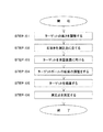
次に、図3のフローチャートを用い、第1の実施例に係る前記ターゲットポール1を用いたプリズム測定を行う場合について説明する。
Next, a case where prism measurement using the
STEP:01 先ず始めに、前記ロックネジ5を緩め、前記ターゲットホルダ3をスライドさせて、前記ターゲット2が所望の高さとなる様該ターゲット2の高さを調整する。
STEP: 01 First, the
STEP:02 次に、所定の前記測定点11上に前記石突き8を置き、前記ターゲットポール1を立てる。
STEP: 02 Next, the
STEP:03 該ターゲットポール1が立てられると、次に前記石突き8を中心に前記ターゲットポール1を水平方向に回転させ、前記ターゲット2を前記測量装置12へと向ける。この時、前記ターゲット2と前記測量装置12とを正確に正対させる必要はなく、前記ターゲット2が概略前記測量装置12に向いていればよい。
STEP: 03 When the
STEP:04 前記ターゲット2を前記測量装置12に向けた後、前記気泡管6が水平を検出する様、前記ターゲットポール1の傾きを調整し、該ターゲットポール1が鉛直となる様支持される。
STEP: 04 After pointing the
STEP:05 該ターゲットポール1の調整が完了すると、前記測量装置12により前記ターゲット2の視準が行われる。尚、該ターゲット2の視準は作業者が前記視準望遠鏡を介して手動で行ってもよいし、該視準望遠鏡を介して取得した画像に基づき画像処理により自動で行ってもよい。
STEP: 05 When the adjustment of the
STEP:06 最後に、前記測距部により、前記ターゲット2を測距し、測距時の水平角、鉛直角と、前記測定点11と前記浮上点9との距離を基に、図示しない制御部が前記測定点11の3次元座標を演算し、該測定点11の測定が完了する。
STEP: 06 Finally, the
尚、前記ターゲット2の追尾を行う場合には、前記追尾部が追尾光を射出し、前記ターゲットポール1の移動中前記ターゲット2の追尾が行われる。前記ターゲットポール1が設置されると、引続き該ターゲット2の測定が行われる。
When tracking the
上述の様に、第1の実施例では、前記ポール4の軸心が、前記オフセット板7により前記石突き8の軸心からオフセットされ、オフセット距離dは前記ポール4の軸心と前記浮上点9との距離と等しくなっている。
As described above, in the first embodiment, the axis of the
従って、前記ターゲットポール1を鉛直とした際には、前記浮上点9を前記石突き8の軸心上、即ち前記測定点11の鉛直上方に位置させることができ、前記ターゲット2は前記浮上点9を中心に回転する。
Therefore, when the
又、前記ターゲットポール1を鉛直とした状態では、前記ターゲット2の向きに拘わらず、前記浮上点9は常に前記測定点11の鉛直上方に位置するので、前記測量装置12で前記ターゲット2を測定した際には、該ターゲット2の向きに拘わらず角度誤差、測定誤差を生じない。
Further, in a state where the
従って、プリズム測定を行なう際に、前記ターゲット2を前記測量装置12に正確に正対させる必要がないので、前記ターゲットポール1の設置が容易となり、作業性を向上させることができる。
Therefore, when performing prism measurement, it is not necessary to accurately face the
更に、前記ターゲット2を保持する前記ターゲットホルダ3が、前記ポール4に沿って摺動自在となっているので、必要に応じて前記ターゲット2の高さを変化させることができる。従って、該ターゲット2の高さを変更する為に、前記ポール4の交換や追加を行う必要がなく、作業性の向上、コストの低減を図ることができる。
Further, since the
尚、第1の実施例では、前記石突き8を前記オフセット板7の下面に固着しているが、前記石突き8を前記オフセット板7に沿って水平方向にスライド可能とし、要求されるオフセット量に応じて前記石突き8の軸心と前記ポール4の軸心との距離dを変更できる様にしてもよい。
In the first embodiment, the
次に、図4に於いて、本発明の第2の実施例に係るターゲットポール1について説明する。尚、図4中、図1中と同等のものには同符号を付し、その説明を省略する。
Next, in FIG. 4, the
第2の実施例では、ターゲットホルダ3の上面に、第1位置合せ部である第1位置合せライン23が形成されている。又、ポール4の周面に、軸心と平行な第2位置合せ部である第2位置合せライン24が全長に亘って形成されている。
In the second embodiment, the
又、前記ポール4は円柱状であり、前記ターゲットホルダ3は前記ポール4に対して上下方向に摺動自在且つ水平方向に回転自在となっている。
Further, the
前記第1位置合せライン23と前記第2位置合せライン24とが合致する位置では、ターゲット2の浮上点9が石突き8の軸心上に位置する。又、前記ポール4の軸心、前記石突き8の軸心、前記ターゲット2の光軸が同一平面上に存在する様になっている。
At the position where the
従って、前記ターゲット2の向きを調整する際には、前記第1位置合せライン23と前記第2位置合せライン24とを合致させる。これにより、前記ターゲットホルダ3の回転位置を容易に決定することができ、作業性を向上させることができる。
Therefore, when adjusting the orientation of the
次に、図5、図6に於いて、本発明の第3の実施例に係るターゲットポール1について説明する。尚、図5、図6中、図1中と同等のものには同符号を付し、その説明を省略する。
Next, in FIGS. 5 and 6, the
第3の実施例では、断面形状が略三角形状の位置合せ溝25が、第1位置合せ部として軸心方向に全長に亘って刻設されている。
In the third embodiment, the
第2位置合せ部としてのロックネジ5の先端は、前記位置合せ溝25内に延出し、前記ロックネジ5の先端は、前記位置合せ溝25の斜面と接触する。前記ロックネジ5の先端が前記位置合せ溝25の斜面2点と接触した際には、前記ポール4に対する前記ターゲットホルダ3の回転が規制され、前記ターゲット2の浮上点9が石突き8の軸心上に位置する様になっている。
The tip of the
前記ターゲット2の上下方向の位置調整を行なう際に、前記ロックネジ5を締め込むことで、前記ロックネジ5の先端が前記位置合せ溝25の斜面に均等に当たる様、ターゲットホルダ3の回転位置が変化する。
By tightening the
従って、前記ターゲット2の上下位置の変更後、前記ロックネジ5を締めるだけで、前記ターゲット2の回転位置も調整されるので、該ターゲット2の回転位置を調整する為の作業が不要となり、作業性を向上させることができる。
Therefore, after changing the vertical position of the
尚、第3の実施例では、前記位置合せ溝25は断面形状が略三角形状の溝としているが、前記位置合せ溝25は断面形状が略四角形状の溝としてもよい。この場合には、前記ロックネジ5の先端をテーパ形状とするのが好ましい。
In the third embodiment, the
次に、図7、図8に於いて、本発明の第4の実施例に係るターゲットポール1について説明する。尚、図7、図8中、図1中と同等のものには同符号を付し、その説明を省略する。
Next, in FIGS. 7 and 8, the
第1〜第3の実施例では、ポール4を円柱状としているが、第4の実施例では、該ポール4を角柱状、例えば四角柱とし、又該ポール4が挿通する孔を四角形状としている。
In the first to third embodiments, the
該ポール4を四角柱状、孔を四角形状とすることで、前記ポール4と孔の嵌合により、ターゲットホルダ3の回転が拘束される。従って、ターゲット2の上下方向の位置調整を行なう際に、前記ターゲットホルダ3に回転方向の位置ズレが生じないので、前記ターゲット2の回転方向の位置調整が不要となり、作業性を向上させることができる。
By making the pole 4 a square columnar shape and a hole having a square shape, the rotation of the
尚、前記ポール4の形状は、三角柱状、六角柱状、更に他の多角柱状としてもよいのは言う迄もない。
Needless to say, the shape of the
次に、図9に於いて、本発明の第5の実施例に係るターゲットポール1について説明する。尚、図9中、図1中と同等のものには同符号を付し、その説明を省略する。
Next, in FIG. 9, the
第5の実施例では、ポール4とオフセット板7とが別部材となっている。該オフセット板7には、ポール挿入孔26が穿設されると共に、該ポール挿入孔26に延出する固定ネジ27が設けられている。又、前記ポール4の下端には、石突き28が設けられている。
In the fifth embodiment, the
前記ポール挿入孔26は、前記ポール4と隙間なく嵌合し、前記ポール挿入孔26の軸心は石突き8の軸心と平行となっている。又、該石突き8の軸心と前記ポール挿入孔26の軸心迄の距離は、ターゲット2の浮上点9と前記ポール4の軸心迄の距離と一致している。
The
該ポール4は、下端を前記ポール挿入孔26に挿入した後、前記固定ネジ27を締めることで、前記オフセット板7に固定される。前記ポール4が前記オフセット板7に取付けられることで、前記石突き8の軸心上に前記浮上点9が位置することとなる。
The
尚、前記ポール4の周面に目盛り等を設け、該ポール4の前記オフセット板7への挿入深さが確認できる構成とするのが望ましい。
It is desirable to provide a scale or the like on the peripheral surface of the
第5の実施例では、前記ポール4とオフセット板7とが着脱可能となっているので、手動で前記ターゲット2の視準を行う場合等、前記浮上点9のオフセットが不要である場合には、前記オフセット板7から前記ポール4を取外し、前記石突き28を測定点11に立てて測定を行うことができる。
In the fifth embodiment, since the
従って、前記オフセット板7に対する前記ポール4の着脱により、前記浮上点9のオフセットを行う場合、行わない場合の使い分けが可能となるので、前記ターゲットポール1の汎用性を高めることができる。
Therefore, by attaching / detaching the
尚、前記ポール4は、石突きの軸心上に浮上点が存在しない従来の種々のターゲットポールであってもよい。この場合、前記オフセット板7と前記石突き8とは、従来のターゲットポールの浮上点を石突きの軸心上に位置させる為のオフセットユニットとして機能する。
The
第5の実施例では、従来のターゲットポールを前記オフセット板7に取付けることで、本実施例に係る前記ターゲットポール1とすることができる。従って、必要となるのは前記オフセット板7と前記石突き8等からなるオフセットユニットのみであり、汎用性を高めると共に、製作コストを低減させることができる。
In the fifth embodiment, the
次に、図10に於いて、本発明の第6の実施例に係るターゲットポール1について説明する。尚、図10中、図4、図9中と同等のものには同符号を付し、その説明を省略する。
Next, in FIG. 10, the
第6の実施例では、第2の実施例と同様、ターゲットホルダ3の上面に第1位置合せ部である第1位置合せライン23が形成され、ポール4の周面に第2位置合せ部である第2位置合せライン24が形成されている。
In the sixth embodiment, as in the second embodiment, the
又、オフセット板7の上面に、第3位置合せ部である第3位置合せライン29が形成されている。その他の構成については、第5の実施例と同様となっている。
Further, a
前記第1位置合せライン23が前記第2位置合せライン24と合致し、前記第2位置合せライン24が前記第3位置合せライン29と合致した際には、石突き8の軸心上にターゲット2の浮上点9が位置する様になっている。
When the
従って、前記ポール4の前記オフセット板7への取付け時には、前記第2位置合せライン24を前記第3位置合せライン29に合致させることで、容易に前記ターゲット2の回転位置を決定することができる。
Therefore, when the
次に図11(A)に於いて、本発明の第7の実施例について説明する。尚、図11(A)中、図1中と同等のものには同符号を付し、その説明を省略する。 Next, a seventh embodiment of the present invention will be described with reference to FIG. 11 (A). In FIG. 11A, those equivalent to those in FIG. 1 are designated by the same reference numerals, and the description thereof will be omitted.
第7の実施例では、ターゲットホルダ3は矩形の枠状となっており、ポール4に沿って摺動可能となっている。ターゲット2は、前記ターゲットホルダ3の内部に収納され、前記ポール4の軸心と直交する軸心を有する回転軸31を介して前記ターゲットホルダ3に回転自在に取付けられている。尚、該ターゲットホルダ3と前記回転軸31との間には、適宜な摩擦力が設けられ、前記ターゲット2は任意の位置で固定可能となっている。
In the seventh embodiment, the
前記ターゲット2は、該ターゲット2の光軸が、前記ポール4の軸心と石突き8の軸心とを含む平面に対して垂直となる様設けられている。
The
石突き8を測定点11に立て、前記ターゲットポール1を鉛直とした際には、前記ターゲット2の浮上点9は、前記回転軸31の軸心上に位置し、又石突き8の軸心上に位置する。
When the
従って、前記ターゲット2は、前記浮上点9の位置を変化させることなく、前記石突き8の軸心を中心に水平回転し、前記回転軸31の軸心を中心に鉛直回転するので、前記ターゲット2をより容易に測量装置12(図2参照)へと向けることができ、作業性を向上させることができる。
Therefore, the
図11(B)は、第7の実施例の変形例を示している。該変形例では、前記ターゲット2の軸心が、前記ポール4の軸心と前記石突き8の軸心とを含む平面内に含まれる様、前記ターゲット2が前記ターゲットホルダ3に設けられている。
FIG. 11B shows a modified example of the seventh embodiment. In the modification, the
次に、図12(A)、図12(B)に於いて、本発明の第8の実施例について説明する。尚、図12(A)、図12(B)中、図1中と同等のものには同符号を付し、その説明を省略する。 Next, an eighth embodiment of the present invention will be described with reference to FIGS. 12 (A) and 12 (B). In FIGS. 12 (A) and 12 (B), those equivalent to those in FIG. 1 are designated by the same reference numerals, and the description thereof will be omitted.
第8の実施例では、ターゲットホルダ3が保持部32とスライド部33とから構成されている。前記保持部32は断面形状がコ字状の部材であり、凹部にターゲット2が収納されている。又、前記保持部32はポール4の軸心と直交する軸心を有する回転軸34を介して前記スライド部33に回転可能に設けられ、前記ターゲット2の光軸は前記回転軸34の軸心に対して直交している。
In the eighth embodiment, the
又、前記スライド部33は、ロックネジ5と気泡管6とを有し、前記ポール4に上下方向に摺動自在に取付けられ、任意の位置で前記ロックネジ5により固定可能となっている。
Further, the
ターゲット2は、該ターゲット2の光軸が、前記ポール4の軸心と石突き8の軸心とを含む面に対して直交する様、前記回転軸34を介して前記保持部32に鉛直回転可能に設けられている。前記ターゲット2の浮上点9は、前記回転軸34の軸心と、前記石突き8の軸心との交点に位置している。尚、前記回転軸34と前記スライド部33との間には、適宜な摩擦力が設けられ、前記保持部32は任意の位置で固定可能となっている。
The
第8の実施例では、前記浮上点9の位置を変化させることなく、前記石突き8の軸心を中心に水平回転し、前記回転軸34の軸心を中心に鉛直回転すると共に、第7の実施例と比較して前記ターゲットホルダ3の構成が簡易となるので、作業性の向上と共に製作コストの低減を図ることができる。
In the eighth embodiment, the
次に、図13(A)、図13(B)、図14(A)〜図14(D)に於いて、本発明の第9の実施例について説明する。尚、図13(A)、図13(B)、図14(A)〜図14(D)中、図12(A)、図12(B)中と同等のものには同符号を付し、その説明を省略する。 Next, a ninth embodiment of the present invention will be described with reference to FIGS. 13 (A), 13 (B), and 14 (A) to 14 (D). The same reference numerals are given to those equivalent to those in FIGS. 13 (A), 13 (B), 14 (A) to 14 (D), 12 (A) and 12 (B). , The description is omitted.
第9の実施例では、ターゲットホルダ3が保持部32とスライド部33とから構成されている。該スライド部33は、ロックネジ5と気泡管6とを有し、ポール4に上下方向に摺動自在に取付けられている。又、前記スライド部33は前記ポール4の軸心と直交する軸心を有する鉛直回転軸35が設けられ、該鉛直回転軸35を介して前記保持部32が前記スライド部33に回転可能に設けられている。又、前記保持部32と前記鉛直回転軸35との間には、適宜な摩擦力が設けられ、前記保持部32は任意の位置で固定可能となっている。
In the ninth embodiment, the
前記保持部32は断面が側方に開放された凹部を有するコ字状の部材となっており、前記鉛直回転軸35の軸心と直交する軸心を有する水平回転軸36が設けられている。又、凹部にはターゲット2が収納され、前記水平回転軸36を介して前記ターゲット2が水平回転可能に設けられている。又、前記保持部32と前記水平回転軸36との間には、適宜な摩擦力が設けられ、前記保持部32は任意の位置で固定可能となっている。
The holding
前記ターゲット2の浮上点9は、前記鉛直回転軸35の軸心と、前記水平回転軸36の軸心と、石突き8の軸心との交点に位置している。尚、前記水平回転軸36の軸心を前記ポール4の軸心と平行とした際には、前記水平回転軸36の軸心は前記石突き8の軸心と一致する。
The
第9の実施例では、前記ターゲット2を前記浮上点9を中心に、即ち該浮上点9の位置を変化させることなく水平回転(図14(A)、図14(B)参照)させることができ、更に鉛直回転(図14(C)、図14(D)参照)させることができる。
In the ninth embodiment, the
前記鉛直回転軸35を介した回転と、前記水平回転軸36を介した回転との協働により、前記ターゲット2を所望の方向に自在に向けることができる。
The
従って、前記ターゲット2のみを測量装置12へと向けるだけでよく、前記ターゲットポール1自体を回転させる必要がないので、壁際等、前記ターゲットポール1の回転が妨げられる位置の測定点11の測定が可能となり、作業性をより向上させることができる。
Therefore, it is only necessary to direct the
次に、図15に於いて、本発明の第10の実施例について説明する。尚、図15中、図9中と同等のものには同符号を付し、その説明を省略する。 Next, a tenth embodiment of the present invention will be described with reference to FIG. The same reference numerals are given to those equivalent to those in FIGS. 15 and 9, and the description thereof will be omitted.
第10の実施例では、オフセット板37が円板状となっており、該オフセット板37の下面には中心から垂下する石突き38が設けられている。又、前記オフセット板37には、複数のポール挿入孔39(図15中では39a〜39d)が穿設されている。
In the tenth embodiment, the offset
該ポール挿入孔39a〜39dは、それぞれ前記石突き38の軸心との距離が異なる位置に穿設され、各ポール挿入孔39a〜39dの軸心と前記石突き38の軸心との距離は既知となっている。
The
前記ポール4を挿入する前記ポール挿入孔39a〜39dを変更することで、前記石突き38の軸心と前記ポール4の軸心との距離d、即ちターゲット2の浮上点9のオフセット量を変更することができる。
By changing the
従って、石突きの軸心上に浮上点が存在しない従来の種々のターゲットポールの使用が可能であり、前記浮上点9のオフセット量を変更する際には、前記ポール4を挿入する前記ポール挿入孔39a〜39dを変更するだけでよい。従って、オフセット量の異なるオフセット板7(図9参照)を複数設ける必要がなく、汎用性が増すと共に製作コストの低減を図ることができる。
Therefore, it is possible to use various conventional target poles having no levitation point on the axis of the ridge, and when changing the offset amount of the
尚、第10の実施例では、前記オフセット板37を円板状としているが、外形形状が三角形や四角形の板等、前記石突き38の軸心からの距離が異なる位置に前記ポール挿入孔を複数穿設可能な板であれば他の形状であってもよい。
In the tenth embodiment, the offset
又、第10の実施例では、前記石突き38を前記オフセット板37に固着させ、前記ポール4を前記オフセット板37に対して着脱可能としているが、前記ポール4を前記オフセット板37に固着させ、前記石突き38を前記オフセット板37に対して着脱可能としてもよい。
Further, in the tenth embodiment, the
この場合、例えば短冊状の該オフセット板37の一端部に前記ポール4を固着させ、該ポール4の軸心との距離が異なる箇所に複数の石突き挿入孔を穿設し、要求されるオフセット量に対応する前記石突き挿入孔に前記石突き38を嵌合させる様にすればよい。
In this case, for example, the
尚、第2の実施例〜第10の実施例に於けるターゲットポール1に於いても、第1の実施例と同様に、測量装置12(図2参照)によりプリズム測定が可能である。
In the
更に、第1の実施例〜第10の実施例は、用途に応じて適宜組合わせ可能であることは言う迄もない。 Further, it goes without saying that the first to tenth embodiments can be appropriately combined according to the intended use.
1 ターゲットポール
2 ターゲット
3 ターゲットホルダ
4 ポール
5 ロックネジ
7 オフセット板
8 石突き
9 浮上点
11 測定点
12 測量装置
13 測量装置本体
18 望遠鏡部
23 第1位置合せライン
24 第2位置合せライン
25 位置合せ溝
26 ポール挿入孔
29 第3位置合せライン
32 保持部
33 スライド部
37 オフセット板
38 石突き
39 ポール挿入孔
1
Claims (10)
Priority Applications (1)
| Application Number | Priority Date | Filing Date | Title |
|---|---|---|---|
| JP2016154523A JP6778044B2 (en) | 2016-08-05 | 2016-08-05 | Target pole and surveying system |
Applications Claiming Priority (1)
| Application Number | Priority Date | Filing Date | Title |
|---|---|---|---|
| JP2016154523A JP6778044B2 (en) | 2016-08-05 | 2016-08-05 | Target pole and surveying system |
Publications (2)
| Publication Number | Publication Date |
|---|---|
| JP2018021867A JP2018021867A (en) | 2018-02-08 |
| JP6778044B2 true JP6778044B2 (en) | 2020-10-28 |
Family
ID=61164762
Family Applications (1)
| Application Number | Title | Priority Date | Filing Date |
|---|---|---|---|
| JP2016154523A Active JP6778044B2 (en) | 2016-08-05 | 2016-08-05 | Target pole and surveying system |
Country Status (1)
| Country | Link |
|---|---|
| JP (1) | JP6778044B2 (en) |
Families Citing this family (3)
| Publication number | Priority date | Publication date | Assignee | Title |
|---|---|---|---|---|
| CN110344454A (en) * | 2019-07-31 | 2019-10-18 | 中交第二航务工程局有限公司 | A kind of impact drill construction stake foundation pile position capacity checking device and its check method |
| JP7288383B2 (en) * | 2019-10-07 | 2023-06-07 | 戸田建設株式会社 | Reference point replacement system for steel frame construction floors |
| DE202021102669U1 (en) * | 2021-05-17 | 2021-05-27 | Georg Rothbucher | Device for marking a survey object |
Family Cites Families (9)
| Publication number | Priority date | Publication date | Assignee | Title |
|---|---|---|---|---|
| US5311222A (en) * | 1988-09-14 | 1994-05-10 | Pyramid Optical | Prism assembly |
| JP2502948Y2 (en) * | 1992-06-26 | 1996-06-26 | エス・ティ・エス株式会社 | Reflector for light-wave rangefinder-Supporting member for equipment |
| JP3075881U (en) * | 2000-08-25 | 2001-03-06 | 株式会社ソキア | Reflective sheet device |
| JP2008014864A (en) * | 2006-07-07 | 2008-01-24 | Topcon Corp | Surveying instrument |
| JP2008203078A (en) * | 2007-02-20 | 2008-09-04 | Techno I System Co Ltd | Mirror device for total station |
| JP5047926B2 (en) * | 2008-10-30 | 2012-10-10 | 株式会社マイゾックス | Surveying tripod |
| US7987605B2 (en) * | 2009-02-23 | 2011-08-02 | Roger Fleenor | Reflector target tripod for survey system with light emitter and pivoting bracket for enhanced ground marking accuracy |
| DE102011116303B3 (en) * | 2011-10-18 | 2012-12-13 | Trimble Jena Gmbh | Geodetic measurement system, has satellite-geodetic system provided with antenna, where system determines relative orientation angle between inclinometers relative to perpendicular orientation of system depending on inclination data |
| US9797719B2 (en) * | 2013-10-01 | 2017-10-24 | Kabushiki Kaisha Topcon | Measuring method and measuring instrument |
-
2016
- 2016-08-05 JP JP2016154523A patent/JP6778044B2/en active Active
Also Published As
| Publication number | Publication date |
|---|---|
| JP2018021867A (en) | 2018-02-08 |
Similar Documents
| Publication | Publication Date | Title |
|---|---|---|
| US7987605B2 (en) | Reflector target tripod for survey system with light emitter and pivoting bracket for enhanced ground marking accuracy | |
| JP6778044B2 (en) | Target pole and surveying system | |
| US8711369B2 (en) | Laser receiver for detecting a relative position | |
| US8712721B2 (en) | Adjustable high precision surveying device | |
| US20150204976A1 (en) | Hand-held distance-measuring device having an angle-determining unit | |
| CN103429395A (en) | Working tool positioning system | |
| EP3136050A1 (en) | Total station | |
| CN103328926A (en) | Measuring appliance comprising an automatic representation-changing functionality | |
| KR100928662B1 (en) | A multipurpose instrument | |
| KR101740994B1 (en) | Structure measuring unit for tracking, measuring and marking edges and corners of adjacent surfaces | |
| US10036799B2 (en) | Device system and method for determining the relative orientation between two different locations | |
| US20220011105A1 (en) | Geodetic instrument comprising a base and a geodetic surveying and/or projection module | |
| JP2016017874A (en) | Surveying device | |
| US6240649B1 (en) | Sighting assembly | |
| KR101604106B1 (en) | Target supporter for light wave surveying instrument theodolite | |
| JP2019219319A (en) | Vertical measurement system and reference point tracing method | |
| JP6179880B2 (en) | Surveying target and total station surveying method | |
| KR101550403B1 (en) | the improved portable prism receiver and the improved portable GPS receiver and the measurement method using the same | |
| US7797845B2 (en) | Levelling device | |
| KR101984507B1 (en) | the improved portable prism receiver and the measurement method using the same | |
| CN105547268B (en) | Sighting device for photoelectric measurement equipment | |
| JPH09243367A (en) | One-leg range finding device | |
| JP3718312B2 (en) | Machine height measuring device | |
| JP7194614B2 (en) | Target pole and survey system | |
| KR101974946B1 (en) | the improved portable prism receiver and the measurement method using the same |
Legal Events
| Date | Code | Title | Description |
|---|---|---|---|
| A621 | Written request for application examination |
Free format text: JAPANESE INTERMEDIATE CODE: A621 Effective date: 20190725 |
|
| A977 | Report on retrieval |
Free format text: JAPANESE INTERMEDIATE CODE: A971007 Effective date: 20200520 |
|
| A131 | Notification of reasons for refusal |
Free format text: JAPANESE INTERMEDIATE CODE: A131 Effective date: 20200602 |
|
| A521 | Request for written amendment filed |
Free format text: JAPANESE INTERMEDIATE CODE: A523 Effective date: 20200730 |
|
| TRDD | Decision of grant or rejection written | ||
| A01 | Written decision to grant a patent or to grant a registration (utility model) |
Free format text: JAPANESE INTERMEDIATE CODE: A01 Effective date: 20200929 |
|
| A61 | First payment of annual fees (during grant procedure) |
Free format text: JAPANESE INTERMEDIATE CODE: A61 Effective date: 20201009 |
|
| R150 | Certificate of patent or registration of utility model |
Ref document number: 6778044 Country of ref document: JP Free format text: JAPANESE INTERMEDIATE CODE: R150 |
|
| R250 | Receipt of annual fees |
Free format text: JAPANESE INTERMEDIATE CODE: R250 |