JP6777784B2 - Manufacturing method for inspection equipment, blister packaging machines and blister packs - Google Patents
Manufacturing method for inspection equipment, blister packaging machines and blister packs Download PDFInfo
- Publication number
- JP6777784B2 JP6777784B2 JP2019038259A JP2019038259A JP6777784B2 JP 6777784 B2 JP6777784 B2 JP 6777784B2 JP 2019038259 A JP2019038259 A JP 2019038259A JP 2019038259 A JP2019038259 A JP 2019038259A JP 6777784 B2 JP6777784 B2 JP 6777784B2
- Authority
- JP
- Japan
- Prior art keywords
- pocket portion
- inspection
- container film
- film
- Prior art date
- Legal status (The legal status is an assumption and is not a legal conclusion. Google has not performed a legal analysis and makes no representation as to the accuracy of the status listed.)
- Active
Links
Images


Classifications
-
- G—PHYSICS
- G01—MEASURING; TESTING
- G01N—INVESTIGATING OR ANALYSING MATERIALS BY DETERMINING THEIR CHEMICAL OR PHYSICAL PROPERTIES
- G01N21/00—Investigating or analysing materials by the use of optical means, i.e. using sub-millimetre waves, infrared, visible or ultraviolet light
- G01N21/84—Systems specially adapted for particular applications
- G01N21/88—Investigating the presence of flaws or contamination
- G01N21/89—Investigating the presence of flaws or contamination in moving material, e.g. running paper or textiles
- G01N21/892—Investigating the presence of flaws or contamination in moving material, e.g. running paper or textiles characterised by the flaw, defect or object feature examined
-
- G—PHYSICS
- G01—MEASURING; TESTING
- G01N—INVESTIGATING OR ANALYSING MATERIALS BY DETERMINING THEIR CHEMICAL OR PHYSICAL PROPERTIES
- G01N21/00—Investigating or analysing materials by the use of optical means, i.e. using sub-millimetre waves, infrared, visible or ultraviolet light
- G01N21/84—Systems specially adapted for particular applications
- G01N21/88—Investigating the presence of flaws or contamination
- G01N21/95—Investigating the presence of flaws or contamination characterised by the material or shape of the object to be examined
- G01N21/9508—Capsules; Tablets
-
- B—PERFORMING OPERATIONS; TRANSPORTING
- B07—SEPARATING SOLIDS FROM SOLIDS; SORTING
- B07C—POSTAL SORTING; SORTING INDIVIDUAL ARTICLES, OR BULK MATERIAL FIT TO BE SORTED PIECE-MEAL, e.g. BY PICKING
- B07C5/00—Sorting according to a characteristic or feature of the articles or material being sorted, e.g. by control effected by devices which detect or measure such characteristic or feature; Sorting by manually actuated devices, e.g. switches
- B07C5/34—Sorting according to other particular properties
- B07C5/342—Sorting according to other particular properties according to optical properties, e.g. colour
-
- B—PERFORMING OPERATIONS; TRANSPORTING
- B65—CONVEYING; PACKING; STORING; HANDLING THIN OR FILAMENTARY MATERIAL
- B65B—MACHINES, APPARATUS OR DEVICES FOR, OR METHODS OF, PACKAGING ARTICLES OR MATERIALS; UNPACKING
- B65B57/00—Automatic control, checking, warning, or safety devices
- B65B57/02—Automatic control, checking, warning, or safety devices responsive to absence, presence, abnormal feed, or misplacement of binding or wrapping material, containers, or packages
-
- G—PHYSICS
- G01—MEASURING; TESTING
- G01N—INVESTIGATING OR ANALYSING MATERIALS BY DETERMINING THEIR CHEMICAL OR PHYSICAL PROPERTIES
- G01N21/00—Investigating or analysing materials by the use of optical means, i.e. using sub-millimetre waves, infrared, visible or ultraviolet light
- G01N21/84—Systems specially adapted for particular applications
- G01N21/88—Investigating the presence of flaws or contamination
- G01N21/8806—Specially adapted optical and illumination features
-
- G—PHYSICS
- G01—MEASURING; TESTING
- G01N—INVESTIGATING OR ANALYSING MATERIALS BY DETERMINING THEIR CHEMICAL OR PHYSICAL PROPERTIES
- G01N21/00—Investigating or analysing materials by the use of optical means, i.e. using sub-millimetre waves, infrared, visible or ultraviolet light
- G01N21/84—Systems specially adapted for particular applications
- G01N21/88—Investigating the presence of flaws or contamination
- G01N21/8851—Scan or image signal processing specially adapted therefor, e.g. for scan signal adjustment, for detecting different kinds of defects, for compensating for structures, markings, edges
-
- G—PHYSICS
- G01—MEASURING; TESTING
- G01N—INVESTIGATING OR ANALYSING MATERIALS BY DETERMINING THEIR CHEMICAL OR PHYSICAL PROPERTIES
- G01N21/00—Investigating or analysing materials by the use of optical means, i.e. using sub-millimetre waves, infrared, visible or ultraviolet light
- G01N21/84—Systems specially adapted for particular applications
- G01N21/88—Investigating the presence of flaws or contamination
- G01N21/95—Investigating the presence of flaws or contamination characterised by the material or shape of the object to be examined
- G01N21/958—Inspecting transparent materials or objects, e.g. windscreens
-
- B—PERFORMING OPERATIONS; TRANSPORTING
- B65—CONVEYING; PACKING; STORING; HANDLING THIN OR FILAMENTARY MATERIAL
- B65B—MACHINES, APPARATUS OR DEVICES FOR, OR METHODS OF, PACKAGING ARTICLES OR MATERIALS; UNPACKING
- B65B9/00—Enclosing successive articles, or quantities of material, e.g. liquids or semiliquids, in flat, folded, or tubular webs of flexible sheet material; Subdividing filled flexible tubes to form packages
- B65B9/02—Enclosing successive articles, or quantities of material between opposed webs
- B65B9/04—Enclosing successive articles, or quantities of material between opposed webs one or both webs being formed with pockets for the reception of the articles, or of the quantities of material
- B65B9/045—Enclosing successive articles, or quantities of material between opposed webs one or both webs being formed with pockets for the reception of the articles, or of the quantities of material for single articles, e.g. tablets
-
- G—PHYSICS
- G01—MEASURING; TESTING
- G01N—INVESTIGATING OR ANALYSING MATERIALS BY DETERMINING THEIR CHEMICAL OR PHYSICAL PROPERTIES
- G01N21/00—Investigating or analysing materials by the use of optical means, i.e. using sub-millimetre waves, infrared, visible or ultraviolet light
- G01N21/84—Systems specially adapted for particular applications
- G01N21/88—Investigating the presence of flaws or contamination
- G01N21/8851—Scan or image signal processing specially adapted therefor, e.g. for scan signal adjustment, for detecting different kinds of defects, for compensating for structures, markings, edges
- G01N2021/8887—Scan or image signal processing specially adapted therefor, e.g. for scan signal adjustment, for detecting different kinds of defects, for compensating for structures, markings, edges based on image processing techniques
Description
本発明は、ブリスターパックのポケット部の成形状態を検査する検査装置、ブリスター包装機及びブリスターパックの製造方法に関する。 The present invention relates to an inspection device for inspecting a molded state of a pocket portion of a blister pack, a blister packaging machine, and a method for manufacturing a blister pack.
従来、医薬品や食料品、電子部品などを包装する包装容器として、ブリスターパックが広く利用されている。中でも、医薬品の分野において、錠剤やカプセル等を包装するために用いられるPTP(プレススルーパッケージ)シートがよく知られている。 Conventionally, blister packs have been widely used as packaging containers for packaging pharmaceuticals, foodstuffs, electronic parts, and the like. Above all, in the field of pharmaceuticals, PTP (press-through package) sheets used for packaging tablets, capsules and the like are well known.
PTPシートは、錠剤などの内容物を収容するためのポケット部が成形された容器フィルムと、その容器フィルムにポケット部の開口側を密封するように取着されたカバーフィルムとから構成されており、ポケット部を外側から押圧し、そこに収容された内容物によって蓋となるカバーフィルムを突き破ることで、該内容物を取出すことができる。 The PTP sheet is composed of a container film in which a pocket portion for accommodating contents such as tablets is formed, and a cover film attached to the container film so as to seal the opening side of the pocket portion. The contents can be taken out by pressing the pocket portion from the outside and breaking through the cover film serving as a lid by the contents contained therein.
かかるPTPシートは、帯状の容器フィルムに対しポケット部を成形するポケット部成形工程、該ポケット部に内容物を充填する充填工程、該ポケット部の開口側を密封するように容器フィルムに対しカバーフィルムを取着する取着工程、該帯状の両フィルムが取着されてなる帯状のPTPフィルムから最終製品となるPTPシートを切り離す切離工程等を経て製造される。 Such a PTP sheet is used for a pocket forming step of forming a pocket portion on a strip-shaped container film, a filling step of filling the pocket portion with contents, and a cover film for the container film so as to seal the opening side of the pocket portion. It is manufactured through an attachment step of attaching, a cutting step of separating the final product PTP sheet from the strip-shaped PTP film to which both the strip-shaped films are attached, and the like.
ここで、ポケット部の成形は、例えば真空成形、圧空成形、プラグ成形、プラグアシスト圧空成形など、部分的に加熱軟化された帯状の容器フィルムの一部(成形予定部)を延伸加工するのが一般的である。 Here, in the molding of the pocket portion, a part (scheduled molding portion) of the partially heat-softened strip-shaped container film such as vacuum forming, compressed air forming, plug forming, and plug-assisted air forming is stretched. It is common.
このため、ポケット部の底部及び側部それぞれの肉厚には相関関係があり、底部が厚ければ側部が薄くなり、底部が薄ければ側部が厚くなる。 Therefore, there is a correlation between the wall thicknesses of the bottom portion and the side portion of the pocket portion, and if the bottom portion is thick, the side portion becomes thin, and if the bottom portion is thin, the side portion becomes thick.
このような底部及び側部の肉厚バランスが崩れた場合には、ポケット部の一部が過度に薄肉となり、ガスバリア性の低下など種々の不具合が発生するおそれがある。特に底部よりも薄肉とされる側部において、過度の薄肉化が懸念される。 When the wall thickness balance between the bottom and the side is lost, a part of the pocket portion becomes excessively thin, and various problems such as deterioration of gas barrier property may occur. In particular, there is a concern about excessive thinning of the side portion, which is thinner than the bottom portion.
これに対し、上記相関関係を利用して、ポケット部の底部を撮像して得られた画像データを基に、ポケット部の側部の成形不良を検出する技術も提案されている(例えば、特許文献1参照)。 On the other hand, a technique for detecting molding defects on the side portion of the pocket portion based on the image data obtained by imaging the bottom portion of the pocket portion using the above correlation has also been proposed (for example, a patent). Reference 1).
しかしながら、特許文献1に係る従来技術では、ポケット部の底部を撮像して得られた画像データを基に、光の透過率と底部の肉厚との関係性から、底部上の各位置における肉厚を算出し、その平均値(底部の平均肉厚)を基に、ポケット部の側部の成形不良を検出する構成となっている。
However, in the prior art according to
このように、ポケット部の側部の成形状態は、概ね底部の肉厚から推定できるが、例え底部の肉厚の平均値や最大値、最小値が所望の値となり、底部の成形状態が適正であると判断される場合であっても、底部の肉厚分布に偏りがある場合や底部の形状が複雑な場合などは、側部が所望の肉厚になっていなかったり、側部の肉厚分布に偏りが生じている場合もある。 In this way, the molding state of the side portion of the pocket portion can be roughly estimated from the wall thickness of the bottom portion, but for example, the average value, the maximum value, and the minimum value of the wall thickness of the bottom portion are desired values, and the molding state of the bottom portion is appropriate. Even if it is determined that the thickness of the bottom is uneven, or if the shape of the bottom is complicated, the side may not have the desired thickness or the side may be thick. The thickness distribution may be biased.
そのため、上記従来技術では、ポケット部の側部の成形不良(肉厚不良)を精度良く検出できないおそれがあった。 Therefore, in the above-mentioned conventional technique, there is a possibility that the molding defect (thickness defect) of the side portion of the pocket portion cannot be detected accurately.
尚、上記課題は、PTP包装に限らず、他のブリスター包装の分野においても内在するものである。 It should be noted that the above problems are inherent not only in PTP packaging but also in other fields of blister packaging.
本発明は、上記事情等に鑑みてなされたものであり、その目的は、ポケット部の側部の成形不良をより精度良く検出可能な検査装置、ブリスター包装機及びブリスターパックの製造方法を提供することにある。 The present invention has been made in view of the above circumstances and the like, and an object of the present invention is to provide an inspection device, a blister packaging machine and a method for manufacturing a blister pack capable of more accurately detecting molding defects on the side portion of a pocket portion. There is.
以下、上記課題を解決するのに適した各手段につき項分けして説明する。なお、必要に応じて対応する手段に特有の作用効果を付記する。 Hereinafter, each means suitable for solving the above problems will be described separately for each item. In addition, the action and effect peculiar to the corresponding means will be added as necessary.
手段1.ブリスターパックのポケット部の成形状態を検査するための検査装置であって、
前記ポケット部が成形された容器フィルムに対し所定の電磁波を照射可能な照射手段と、
前記容器フィルムを介して前記照射手段とは反対側に設けられ、少なくとも前記ポケット部の底部を透過した前記電磁波を撮像し画像データを取得可能な撮像手段と、
前記撮像手段により取得された画像データを基に、前記電磁波の照射により前記ポケット部の底部に生じる濃淡模様(濃淡分布像)を抽出可能な濃淡模様抽出手段と、
前記濃淡模様抽出手段により抽出された濃淡模様を、予め設定された所定の判定基準と比較することにより、少なくとも前記ポケット部の側部の成形状態に関する良否判定を実行可能な良否判定手段とを備えたことを特徴とする検査装置。
An irradiation means capable of irradiating a container film on which the pocket portion is formed with a predetermined electromagnetic wave,
An imaging means provided on the side opposite to the irradiation means via the container film and capable of capturing at least the electromagnetic wave transmitted through the bottom of the pocket portion and acquiring image data.
Based on the image data acquired by the imaging means, a shading pattern extracting means capable of extracting a shading pattern (shading distribution image) generated at the bottom of the pocket portion by irradiation with the electromagnetic wave, and a shading pattern extracting means.
By comparing the shading pattern extracted by the shading pattern extracting means with a predetermined determination standard set in advance, it is provided with a pass / fail determining means capable of performing a pass / fail judgment regarding at least the molding state of the side portion of the pocket portion. An inspection device characterized by the fact that.
尚、上記「ブリスターパック」には、例えば錠剤等を収容するPTPシート、食料品等を収容するポーションパック、電子部品等を収容するキャリアテープなどが含まれ、上記「電磁波」には、例えば可視光、紫外光、X線などが含まれる。 The "blister pack" includes, for example, a PTP sheet for containing tablets and the like, a portion pack for storing foodstuffs and the like, a carrier tape for containing electronic parts and the like, and the "electromagnetic wave" includes, for example, visible light. Includes light, ultraviolet light, X-rays and the like.
また、上記「前記電磁波の照射により前記ポケット部の底部に生じる濃淡模様(濃淡分布像)」とは、ポケット部の底部上の各位置(二次元座標位置)における肉厚の違い(肉厚分布)と、そこを透過する電磁波の透過率等との関係から、ポケット部の底部に生じる濃淡の二次元分布像を意味する。 Further, the above-mentioned "shading pattern (shading distribution image) generated at the bottom of the pocket portion by irradiation of the electromagnetic wave" is a difference in wall thickness (thickness distribution) at each position (two-dimensional coordinate position) on the bottom of the pocket portion. ) And the transmittance of the electromagnetic waves that pass through it, meaning a two-dimensional distribution image of the shades that occur at the bottom of the pocket.
つまり、ここでいう「濃淡」とは、ポケット部の底部上の各位置を透過した電磁波の強度(輝度)の大小を意味する。従って、上記「前記電磁波の照射により前記ポケット部の底部に生じる濃淡模様(濃淡分布像)」との表現は、例えば「ポケット部の底部を透過した電磁波の強度分布像」や「ポケット部の底部の各位置における肉厚の違いにより各位置で異なる電磁波強度(輝度)の二次元分布像」、「ポケット部の底部の肉厚分布に対応した濃淡分布像(電磁波強度分布像、輝度分布像)」などの表現に置き換えることもできる。 That is, the "shade" here means the magnitude of the intensity (luminance) of the electromagnetic wave transmitted through each position on the bottom of the pocket portion. Therefore, the expression "the shade pattern (shade distribution image) generated at the bottom of the pocket portion by the irradiation of the electromagnetic wave" is, for example, "the intensity distribution image of the electromagnetic wave transmitted through the bottom portion of the pocket portion" or "the bottom portion of the pocket portion". "Two-dimensional distribution image of electromagnetic wave intensity (brightness) that differs at each position due to the difference in wall thickness at each position", "Shadow distribution image corresponding to the wall thickness distribution at the bottom of the pocket (electromagnetic wave intensity distribution image, brightness distribution image) It can also be replaced with an expression such as ".
上記「背景技術」で述べたように、容器フィルムを部分的に延伸して成形されるポケット部の底部及び側部それぞれの肉厚には相関関係があり、底部が厚ければ側部が薄くなり、底部が薄ければ側部が厚くなる。 As described in the above "background technology", there is a correlation between the wall thickness of the bottom and the side of the pocket formed by partially stretching the container film, and the thicker the bottom, the thinner the side. The thinner the bottom, the thicker the sides.
このような相関関係を利用して、上記手段1では、所定の電磁波を照射しつつ、ポケット部の底部を撮像して得られた画像データから、ポケット部の底部に生じた濃淡模様(すなわち底部の肉厚分布状態)を抽出し、これを所定の判定基準と比較することにより、少なくともポケット部の側部の成形状態に関する良否判定を行う構成となっている。
Utilizing such a correlation, in the
一例として、検査対象となるポケット部の底部に生じる濃淡模様と、予め取得した所定の判定基準(例えば良品のポケット部の底部に生じた濃淡模様)とをパターンマッチング等の手法により比較し、その一致度により良否判定を行う構成などを挙げることができる。 As an example, a shading pattern generated at the bottom of a pocket to be inspected is compared with a predetermined criterion (for example, a shading pattern generated at the bottom of a non-defective pocket) obtained in advance by a method such as pattern matching. A configuration in which a pass / fail judgment is made based on the degree of agreement can be mentioned.
かかる構成により、ポケット部の側部における肉厚分布の偏りの有無など、ポケット部の側部の成形不良(肉厚不良)をより精度良く検出することができる。 With such a configuration, it is possible to more accurately detect molding defects (poor wall thickness) on the side portion of the pocket portion, such as the presence or absence of unevenness in the wall thickness distribution on the side portion of the pocket portion.
尚、ポケット部の側部の成形状態を検査するにあたり、側部を直接撮像し検査することも考えられる。この場合、ガスバリア性などを考慮し、側部全周の成形状態を把握する必要がある。しかしながら、側部を直接撮像する構成の下、側部全周の成形状態を把握するには多くの時間又は大掛かりな装置を要するため、ブリスターパックの生産性が低下するおそれがある。 When inspecting the molding state of the side portion of the pocket portion, it is conceivable to directly image and inspect the side portion. In this case, it is necessary to grasp the molding state of the entire circumference of the side portion in consideration of gas barrier properties and the like. However, under the configuration in which the side portion is directly imaged, it takes a lot of time or a large-scale device to grasp the molding state of the entire circumference of the side portion, so that the productivity of the blister pack may decrease.
この点、本手段によれば、ポケット部の底部を撮像し、その成形状態を把握することに基づき、側部全周の成形状態を短期かつ簡単に把握することができる構成となっているため、検査の高速化、ひいてはブリスターパックの生産性の向上を図ることができる。 In this regard, according to this means, the molding state of the entire circumference of the side portion can be easily grasped in a short period of time based on imaging the bottom portion of the pocket portion and grasping the molding state thereof. , The inspection speed can be increased, and the productivity of the blister pack can be improved.
手段2.前記良否判定手段は、
前記濃淡模様を所定の閾値で二値化した上で、これにより得られた二値模様(二値分布像)のうち、前記閾値以上となる明部の連結成分である明部模様(明部分布像)又は前記閾値未満となる暗部の連結成分である暗部模様(暗部分布像)を、所定の判定基準と比較することにより、前記良否判定を実行することを特徴とする手段1に記載の検査装置。
After binarizing the shading pattern with a predetermined threshold value, among the binary patterns (binary distribution image) obtained by this, the bright part pattern (bright part) which is a connected component of the bright part having the threshold value or more. The
上記手段2によれば、濃淡模様を二値化した二値模様を所定の判定基準と比較することにより良否判定を行う構成となっているため、良否判定処理の簡素化を図ることができる。結果として、さらなる検査の高速化、ひいてはブリスターパックの生産性の向上を図ることができる。
According to the
手段3.前記良否判定手段は、
前記明部模様又は前記暗部模様の境界部(輪郭部)の位置が、所定の判定基準を満たすか否か(所定の許容範囲内にあるか否か)を判定することにより、前記良否判定を行うことを特徴とする手段2に記載の検査装置。
Means 3. The pass / fail determination means
The quality determination is made by determining whether or not the position of the boundary portion (contour portion) of the bright portion pattern or the dark portion pattern satisfies a predetermined determination criterion (whether or not it is within a predetermined allowable range). The inspection apparatus according to
上記手段3によれば、明部模様又は暗部模様の全域について、所定の判定基準と比較する構成に比べて、良否判定処理のさらなる簡素化を図ることができる。結果として、さらなる検査の高速化、ひいてはブリスターパックの生産性の向上を図ることができる。
According to the
手段4.前記良否判定手段は、
前記濃淡模様を構成する各画素(濃淡模様上の各位置)における輝度がそれぞれ所定の判定基準を満たすか否か(所定の許容範囲内にあるか否か)を判定し、該判定基準を満たさない画素を不良領域として把握した上で、該不良領域が所定の判定基準を満たすか否か(所定の許容範囲内にあるか否か)を判定することにより、前記良否判定を行うことを特徴とする手段1に記載の検査装置。
It is determined whether or not the brightness of each pixel (each position on the shade pattern) constituting the shade pattern satisfies a predetermined determination criterion (whether or not it is within a predetermined allowable range), and the determination criterion is satisfied. The feature is that the quality determination is performed by grasping the missing pixels as a defective region and then determining whether or not the defective region satisfies a predetermined determination criterion (whether or not it is within a predetermined allowable range). The inspection device according to the
上記手段4によれば、ポケット部の底部に係る濃淡模様を構成する各画素における輝度がそれぞれ所定の判定基準を満たすか否かを判定した上で、ポケット部の側部の成形状態に関する良否判定を行う構成となっている。これにより、ポケット部の成形状態に関するより細やかな検査を行うことができ、ポケット部の成形不良をより精度良く検出することができる。 According to the above means 4, after determining whether or not the brightness of each pixel constituting the shade pattern related to the bottom portion of the pocket portion satisfies a predetermined determination criterion, a quality determination regarding the molding state of the side portion of the pocket portion is made. It is configured to perform. As a result, a more detailed inspection regarding the molding state of the pocket portion can be performed, and a molding defect of the pocket portion can be detected more accurately.
手段5.前記容器フィルムは、透光性を有する樹脂フィルム材料により構成され、
前記照射手段は、前記電磁波として紫外光(例えば200nm以上280nm以下の範囲内にピーク波長をもつ紫外光など)を照射可能に構成されていることを特徴とする手段1乃至4のいずれかに記載の検査装置。
The irradiation means is described in any one of
容器フィルムが透光性を有する樹脂フィルム材料により構成されている場合において、仮に照射手段から可視光が照射される構成となっている場合には、ポケット部の底部の薄肉部位と厚肉部位における光の透過率に差が生じにくくなるおそれがある。つまり、底部全体が一様となり、濃淡模様が生じにくくなるおそれがある。結果として、検査を適切に行うことが困難となるおそれがある。 When the container film is made of a translucent resin film material and is configured to be irradiated with visible light from the irradiating means, the thin-walled portion and the thick-walled portion at the bottom of the pocket portion. There is a risk that the difference in light transmittance will be less likely to occur. That is, the entire bottom portion becomes uniform, and there is a possibility that a shading pattern is less likely to occur. As a result, it may be difficult to perform the inspection properly.
これに対し、上記手段5によれば、透光性を有する樹脂フィルム材料により構成された容器フィルムに対し紫外光を照射する構成となっている。 On the other hand, according to the above means 5, the container film made of the translucent resin film material is irradiated with ultraviolet light.
紫外光は、可視光に比べて透過率が低く、透光性を有する容器フィルムを透過しにくいため、ポケット部の成形状態に関する検査をより適切に行うことができる。 Since ultraviolet light has a lower transmittance than visible light and is difficult to transmit through a translucent container film, it is possible to more appropriately inspect the molding state of the pocket portion.
尚、ここで「透光性を有する樹脂フィルム材料」には、例えば『光が透過する性質(透光性)を有するフィルムであって、電磁波(光)の透過率が極めて高く、当該フィルムを通してその向こう側が透けて見える「透明の樹脂フィルム材料」』や、『透光性は有しているが、透過する電磁波(光)が拡散される又は電磁波(光)の透過率が低いため、人の肉眼では、該フィルムを通して向こう側にある物の形状等を明確に認識できない又は全く認識できない「半透明の樹脂フィルム材料」』などが含まれる。 Here, the "translucent resin film material" includes, for example, "a film having a property of transmitting light (translucency), which has an extremely high transmission rate of electromagnetic waves (light), and is passed through the film. "Transparent resin film material" that allows the other side to be seen through, and "People who have translucency but transmit electromagnetic waves (light) are diffused or the transmittance of electromagnetic waves (light) is low. Includes "semi-transparent resin film material" in which the shape of an object on the other side through the film cannot be clearly recognized or recognized at all.
また、「透明」及び「半透明」は、透光性を有するフィルムの材質を示す表現であり、色彩の有無とは無関係である。従って、「透明」又は「半透明」のフィルムには、例えば「無色透明」又は「無色半透明」のフィルムは勿論のこと、「有色透明」又は「有色半透明」のフィルムも含まれる。 Further, "transparent" and "translucent" are expressions indicating the material of the film having translucency, and are irrelevant to the presence or absence of color. Therefore, the "transparent" or "translucent" film includes, for example, a "colorless transparent" or "colorless translucent" film, as well as a "colored transparent" or "colored translucent" film.
手段6.前記電磁波には、前記容器フィルム(例えばポリプロピレンやポリ塩化ビニル等の樹脂フィルム材料)の透過率が15パーセント以上かつ60パーセント以下となる波長の電磁波が含まれることを特徴とする手段1乃至5のいずれかに記載の検査装置。
Means 6. 1. The electromagnetic wave of
容器フィルムを透過する電磁波の透過率が高すぎても低すぎても、ポケット部の底部の薄肉部位と厚肉部位における光の透過率に差が生じにくくなるおそれがある。結果として、検査を適切に行うことが困難となるおそれがある。 If the transmittance of the electromagnetic wave transmitted through the container film is too high or too low, the difference in light transmittance between the thin-walled portion and the thick-walled portion at the bottom of the pocket portion may be less likely to occur. As a result, it may be difficult to perform the inspection properly.
これに対し、上記手段6のように、容器フィルムの透過率が15パーセント以上かつ60パーセント以下となる波長の電磁波を用いることで、検査をより適切に行うことができる。より好ましくは、容器フィルムの透過率が20パーセント以上かつ50パーセント以下(例えば30パーセント)となる波長の電磁波を用いて検査を行うことが好ましい。 On the other hand, by using an electromagnetic wave having a wavelength such that the transmittance of the container film is 15% or more and 60% or less as in the above means 6, the inspection can be performed more appropriately. More preferably, the inspection is performed using an electromagnetic wave having a wavelength at which the transmittance of the container film is 20% or more and 50% or less (for example, 30%).
手段7.前記判定基準は、
前記撮像手段により良品のポケット部を撮像して得られた前記濃淡模様に基づいて定められることを特徴とする手段1乃至6のいずれかに記載の検査装置。
Means 7. The criterion is
The inspection apparatus according to any one of
上記手段7によれば、ポケット部の底部の形状や肉厚分布が複雑である場合であっても、比較的容易に判定基準を設定することができる。 According to the above means 7, even when the shape of the bottom portion of the pocket portion and the wall thickness distribution are complicated, the determination criteria can be set relatively easily.
手段8.前記ポケット部は、平坦な前記容器フィルムに熱成形されたものであることを特徴とする手段1乃至7のいずれかに記載の検査装置。
Means 8. The inspection apparatus according to any one of
ここで、「熱成形」とは、平坦な容器フィルムの一部(成形予定部)を部分的に加熱軟化させ延伸加工する成形方法であり、例えば真空成形、圧空成形、プラグ成形、プラグアシスト圧空成形などが含まれる。 Here, "thermoforming" is a molding method in which a part (scheduled molding portion) of a flat container film is partially heated and softened and stretched. For example, vacuum forming, compressed air forming, plug forming, plug assisted air forming. Molding etc. are included.
従って、本手段8に係る構成の下において、上記手段1等の作用効果がより奏効することとなる。 Therefore, under the configuration according to the present means 8, the effects of the above means 1 and the like are more effective.
手段9.手段1乃至8のいずれかに記載の検査装置を備えたことを特徴とするブリスター包装機。
Means 9. A blister packaging machine provided with the inspection device according to any one of
上記手段9のように、上記検査装置をブリスター包装機(例えばPTP包装機)に備えることで、ブリスターパック(例えばPTPシート)の製造過程において不良品を効率的に除外できる等のメリットが生じる。また、ブリスター包装機は、上記検査装置によって不良と判定されたブリスターパックを排出する排出手段を備える構成としてもよい。 By providing the inspection device in the blister packaging machine (for example, PTP packaging machine) as in the above means 9, there is an advantage that defective products can be efficiently excluded in the manufacturing process of the blister pack (for example, PTP sheet). Further, the blister packaging machine may be configured to include a discharge means for discharging the blister pack determined to be defective by the inspection device.
より具体的なブリスター包装機の構成として、以下のような構成が挙げられる。 As a more specific configuration of the blister packaging machine, the following configuration can be mentioned.
「容器フィルムに成形されたポケット部に所定の内容物が収容され、該ポケット部を塞ぐようにカバーフィルムが取着されてなるブリスターパックを製造するためのブリスター包装機であって、
帯状に搬送される前記容器フィルムに対し前記ポケット部を成形するポケット部成形手段と、
前記ポケット部に前記内容物を充填する充填手段と、
前記ポケット部に前記内容物が充填された前記容器フィルムに対し、前記ポケット部を塞ぐようにして帯状の前記カバーフィルムを取着する取着手段と、
前記容器フィルムに前記カバーフィルムが取着された帯状体(帯状のブリスターフィルム)から前記ブリスターパックを切離す切離手段(シート単位に打抜く打抜手段を含む)と、
手段1乃至8のいずれかに記載の検査装置とを備えたことを特徴とするブリスター包装機。」。
"A blister packaging machine for manufacturing a blister pack in which a predetermined content is housed in a pocket formed into a container film and a cover film is attached so as to close the pocket.
A pocket portion molding means for molding the pocket portion on the container film conveyed in a strip shape,
A filling means for filling the pocket portion with the contents,
An attachment means for attaching the band-shaped cover film to the container film in which the pocket portion is filled with the contents so as to close the pocket portion.
A cutting means for separating the blister pack from a strip-shaped body (belt-shaped blister film) to which the cover film is attached to the container film (including a punching means for punching in sheet units).
A blister packaging machine including the inspection device according to any one of
尚、仮に姿勢の定まらない容器フィルムを検査する場合には、ポケット部の位置を特定する処理を実行しなければならないのは勿論のこと、非円形状のポケット部の場合には、画像データから検査対象となるポケット部の中心位置を算出し、該ポケット部の中心位置に、予め記憶したパターンマッチング用の基準画像の中心を合わせた上で、該基準画像を所定角度ずつ回転させていき、両者が一致するか否かをその都度判定するといった処理を行わなければならず、ポケット部に係る検査が非常に処理数が多く、手間のかかるものとなるおそれがある。 In addition, when inspecting a container film whose posture is not fixed, it is of course necessary to execute a process of specifying the position of the pocket portion, and in the case of a non-circular pocket portion, from the image data. The center position of the pocket portion to be inspected is calculated, the center of the reference image for pattern matching stored in advance is aligned with the center position of the pocket portion, and then the reference image is rotated by a predetermined angle. It is necessary to perform a process such as determining whether or not the two match each time, and the number of processes for the inspection related to the pocket portion is very large, which may be troublesome.
これに対し、上記手段9のように、ブリスター包装機上に上記検査装置を備えることにより、撮像手段に対する容器フィルムの停止位置や向き(姿勢)が一定となるため、検査対象となるポケット部の底部に生じる濃淡模様と、予め取得した所定の判定基準(例えば良品のポケット部の底部に生じた濃淡模様)とを比較する場合においても、検査対象と判定基準の位置合わせや、検査対象に合わせて判定基準の向き(姿勢)を回転させるなどの調整を行う必要がないため、検査の高速化を図ることができる。結果として、1つのポケット部にかかる処理数が格段に減り、検査処理速度を格段に速めることができる。 On the other hand, by providing the inspection device on the blister packaging machine as in the means 9, the stop position and orientation (posture) of the container film with respect to the imaging means become constant, so that the pocket portion to be inspected Even when comparing the shading pattern generated on the bottom with a predetermined judgment standard (for example, the shading pattern generated on the bottom of the pocket of a non-defective product), the inspection target and the judgment standard are aligned and the inspection target is matched. Since it is not necessary to make adjustments such as rotating the direction (posture) of the judgment standard, the inspection speed can be increased. As a result, the number of processes applied to one pocket portion is remarkably reduced, and the inspection processing speed can be remarkably increased.
さらに、上記手段9に係る構成の下、
「前記検査装置よりも下流側に前記充填手段を配置し、
前記検査装置による検査結果に基づき前記充填手段の動作を制御し、前記ポケット部に対する前記内容物の充填の可否を切換可能な充填制御手段を備えた」構成としてもよい。
Further, under the configuration according to the above means 9,
"The filling means is arranged on the downstream side of the inspection device, and the filling means is arranged.
The configuration may include a filling control means capable of controlling the operation of the filling means based on the inspection result by the inspection device and switching whether or not the contents can be filled in the pocket portion.
かかる構成により、例えば成形不良のポケット部に対しては内容物を充填しないようにすることも可能となる。これにより、ポケット部の成形不良に起因してブリスターパックが廃棄される場合において、該ブリスターパックとともに内容物までも廃棄されてしまうといった不具合の発生を防止することができる。また、内容物を再利用するために、ポケット部に一旦充填した内容物を取出す等の面倒な作業を行う必要がなくなる。結果として、生産性の低下抑制を図ることができる。 With such a configuration, for example, it is possible to prevent the contents from being filled in the poorly molded pocket portion. As a result, when the blister pack is discarded due to poor molding of the pocket portion, it is possible to prevent the occurrence of a problem that the contents are also discarded together with the blister pack. Further, in order to reuse the contents, it is not necessary to perform troublesome work such as taking out the contents once filled in the pocket portion. As a result, it is possible to suppress a decrease in productivity.
また、上記手段9に係る構成の下、
「前記ポケット部成形手段は、第一の型と、該第一の型と前記容器フィルムを介して相対する第二の型と、該両型により挟まれた前記容器フィルムに対し前記ポケット部を成形する延伸手段(延伸成形手段)とを備えた」構成としてもよい。
Further, under the configuration according to the above means 9,
"The pocket portion forming means forms the pocket portion with respect to the first mold, the second mold facing the first mold via the container film, and the container film sandwiched between the two molds. It may be configured as "providing a stretching means (stretch molding means) for molding".
かかる構成においては、上記「背景技術」で述べたようなポケット部の底部と側部の肉厚の相関関係、すなわち底部の肉厚が厚ければ側部の肉厚が薄くなり、底部の肉厚が薄ければ側部の肉厚が厚くなるといった相関関係が生じるため、ポケット部の底部を撮像して得られた画像データを基に、ポケット部の側部の成形不良を検出するといった上記手段1等の作用効果がより奏効することとなる。
In such a configuration, the correlation between the bottom wall thickness of the pocket portion and the side wall thickness as described in the above-mentioned "background technique", that is, if the bottom wall thickness is thick, the side wall thickness becomes thin and the bottom wall thickness becomes thin. If the thickness is thin, there is a correlation that the wall thickness of the side portion becomes thick. Therefore, based on the image data obtained by imaging the bottom portion of the pocket portion, the molding defect of the side portion of the pocket portion is detected. The action and effect of the
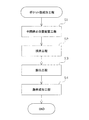
手段10.容器フィルムに成形されたポケット部に所定の内容物が収容され、該ポケット部を塞ぐようにカバーフィルムが取着されてなるブリスターパックの製造方法であって、
帯状に搬送される前記容器フィルムに対し前記ポケット部を成形するポケット部成形工程と、
前記ポケット部に前記内容物を充填する充填工程と、
前記ポケット部に前記内容物が充填された前記容器フィルムに対し、前記ポケット部を塞ぐようにして帯状の前記カバーフィルムを取着する取着工程と、
前記容器フィルムに前記カバーフィルムが取着された帯状体(帯状のブリスターフィルム)から前記ブリスターパックを切離す切離工程(シート単位に打抜く打抜工程を含む)と、
前記ブリスターパックのポケット部の成形状態を検査する検査工程とを備え、
前記検査工程において、
前記ポケット部が成形された容器フィルムに対し所定の電磁波を照射する照射工程と、
少なくとも前記ポケット部の底部を透過した前記電磁波を撮像し画像データを取得する撮像工程と、
前記撮像により取得された画像データを基に、前記電磁波の照射により前記ポケット部の底部に生じる濃淡模様(濃淡分布像)を抽出する濃淡模様抽出工程と、
前記抽出された濃淡模様を、予め設定された所定の判定基準と比較することにより、少なくとも前記ポケット部の側部の成形状態に関する良否判定を行う良否判定工程とを備えたことを特徴とするブリスターパックの製造方法。
A pocket portion molding step of molding the pocket portion on the container film conveyed in a strip shape,
A filling step of filling the pocket with the contents,
An attachment step of attaching the band-shaped cover film to the container film in which the pocket portion is filled with the contents so as to close the pocket portion.
A cutting step of separating the blister pack from a strip-shaped body (belt-shaped blister film) to which the cover film is attached to the container film (including a punching step of punching in sheet units).
It is provided with an inspection process for inspecting the molding state of the pocket portion of the blister pack.
In the inspection process
An irradiation step of irradiating a container film on which the pocket portion is formed with a predetermined electromagnetic wave, and
An imaging step of capturing at least the electromagnetic wave transmitted through the bottom of the pocket portion and acquiring image data,
Based on the image data acquired by the imaging, a shading pattern extraction step of extracting a shading pattern (shading distribution image) generated at the bottom of the pocket portion by irradiation with the electromagnetic wave, and a shading pattern extraction step.
The blister is characterized by comprising a quality determination step of at least determining the quality of the molding state of the side portion of the pocket portion by comparing the extracted shade pattern with a predetermined determination standard set in advance. How to make a pack.
上記手段10によれば、上記手段1,9と同様の作用効果が奏される。
According to the
〔第1実施形態〕
以下に、一実施形態について図面を参照しつつ説明する。まず、ブリスターパックとしてのPTPシート1について説明する。
[First Embodiment]
Hereinafter, one embodiment will be described with reference to the drawings. First, the
図1,2に示すように、PTPシート1は、複数のポケット部2を備えた容器フィルム3と、ポケット部2を塞ぐようにして容器フィルム3に取着されたカバーフィルム4とを有している。
As shown in FIGS. 1 and 2, the
容器フィルム3は、例えばPP(ポリプロピレン)やPVC(ポリ塩化ビニル)等の無色透明な熱可塑性樹脂材料により形成され、透光性を有している。一方、カバーフィルム4は、例えばポリプロピレン樹脂等からなるシーラントが表面に設けられた不透明材料(例えばアルミニウム箔等)により構成されている。
The
PTPシート1は、平面視略矩形状に形成されている。PTPシート1には、その長手方向に沿って配列された5個のポケット部2からなるポケット列が、その短手方向に2列形成されている。つまり、計10個のポケット部2が形成されている。各ポケット部2には、内容物としての錠剤5が1つずつ収容されている。
The
ポケット部2は、カバーフィルム4と相対向するように配置される平面視略円形状の底部2aと、該底部2aの周囲に連接しかつ該底部2aとフィルム平坦部(ポケット非成形部)3bとを繋ぐ略円筒形状の側部2bとから構成されている。
The
本実施形態における底部2aは、緩やかに湾曲した断面略円弧状に成形されているが、これに限らず、底部2aが平坦状に成形された構成としてもよい。また、底部2a及び側部2bが交わる角部2cが明らかでないような、より曲率の大きい断面円弧状に成形された構成としてもよい。
The
PTPシート1(図1参照)は、帯状の容器フィルム3及び帯状のカバーフィルム4から形成された帯状のPTPフィルム6(図3参照)が矩形シート状に打抜かれることにより製造される。
The PTP sheet 1 (see FIG. 1) is manufactured by punching a strip-shaped PTP film 6 (see FIG. 3) formed from a strip-shaped
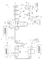
次に、上記PTPシート1を製造するブリスター包装機としてのPTP包装機11の概略構成について図5を参照して説明する。
Next, a schematic configuration of the
PTP包装機11の最上流側では、帯状の容器フィルム3の原反がロール状に巻回されている。ロール状に巻回された容器フィルム3の引出し端側は、ガイドロール13に案内されている。容器フィルム3は、ガイドロール13の下流側において間欠送りロール14に掛装されている。間欠送りロール14は、間欠的に回転するモータに連結されており、容器フィルム3を間欠的に搬送する。
On the most upstream side of the
ガイドロール13と間欠送りロール14との間には、容器フィルム3の搬送経路に沿って、加熱装置15とポケット部成形装置16とが順に配設されている。加熱装置15及びポケット部成形装置16によって、本実施形態におけるポケット部成形手段が構成される。加熱装置15及びポケット部成形装置16の構成については、後に詳述する。
A
ここで、加熱装置15によって容器フィルム3が加熱されて該容器フィルム3が比較的柔軟になった状態において、ポケット部成形装置16によって容器フィルム3の所定位置に複数のポケット部2が一度に成形される(ポケット部成形工程)。尚、ポケット部2の成形は、間欠送りロール14による容器フィルム3の搬送動作間のインターバル中に行われる。
Here, in a state where the
また、ガイドロール13と間欠送りロール14との間であって、ポケット部成形装置16の下流には、ポケット部検査装置21が配設されている。
Further, a pocket
ポケット部検査装置21は、ポケット部成形装置16によって成形されたポケット部2の成形状態に関する検査を行うためのものである。ポケット部検査装置21の構成については、後に詳述する。
The pocket
間欠送りロール14から送り出された容器フィルム3は、テンションロール18、ガイドロール19及びフィルム受けロール20の順に掛装されている。
The
フィルム受けロール20は、一定回転するモータに連結されているため、容器フィルム3を連続的に且つ一定速度で搬送する。テンションロール18は、容器フィルム3を弾性力によって緊張する側へ引っ張った状態とされており、間欠送りロール14とフィルム受けロール20との搬送動作の相違による容器フィルム3の弛みを防止して容器フィルム3を常時緊張状態に保持する。
Since the
ガイドロール19とフィルム受けロール20との間には、容器フィルム3の搬送経路に沿って、錠剤充填装置22が配設されている。
A
錠剤充填装置22は、ポケット部2に錠剤5を自動的に充填する充填手段としての機能を有する。錠剤充填装置22は、フィルム受けロール20による容器フィルム3の搬送動作と同期して、所定間隔毎にシャッタを開くことで錠剤5を落下させるものであり、このシャッタ開放動作に伴って各ポケット部2に錠剤5が充填される。錠剤充填装置22の動作は、後述する充填制御装置82によって制御される。
The
一方、帯状に形成されたカバーフィルム4の原反は、最上流側においてロール状に巻回されている。ロール状に巻回されたカバーフィルム4の引出し端は、ガイドロール24によって加熱ロール25の方へと案内されている。加熱ロール25は、フィルム受けロール20に圧接可能となっており、両ロール20,25間に容器フィルム3及びカバーフィルム4が送り込まれるようになっている。
On the other hand, the original fabric of the
そして、容器フィルム3及びカバーフィルム4が、両ロール20,25間を加熱圧接状態で通過することで、容器フィルム3にカバーフィルム4が貼着され、ポケット部2がカバーフィルム4で塞がれる(取着工程)。これにより、錠剤5が各ポケット部2に収容された帯状体としてのPTPフィルム6が製造される。フィルム受けロール20及び加熱ロール25により本実施形態における取着手段が構成される。
Then, the
フィルム受けロール20から送り出されたPTPフィルム6は、テンションロール27及び間欠送りロール28の順に掛装されている。
The PTP film 6 fed from the
間欠送りロール28は、間欠的に回転するモータに連結されているため、PTPフィルム6を間欠的に搬送する。テンションロール27は、PTPフィルム6を弾性力によって緊張する側へ引っ張った状態とされており、フィルム受けロール20と間欠送りロール28との搬送動作の相違によるPTPフィルム6の弛みを防止してPTPフィルム6を常時緊張状態に保持する。
Since the
間欠送りロール28から送り出されたPTPフィルム6は、テンションロール31及び間欠送りロール32の順に掛装されている。
The PTP film 6 fed from the
間欠送りロール32は、間欠的に回転するモータに連結されているため、PTPフィルム6を間欠的に搬送する。テンションロール31は、PTPフィルム6を弾性力によって緊張する側へ引っ張った状態とされており、間欠送りロール28,32間でのPTPフィルム6の弛みを防止する。
Since the
間欠送りロール28とテンションロール31との間には、PTPフィルム6の搬送経路に沿って、スリット成形装置33及び刻印装置34が順に配設されている。スリット成形装置33は、PTPフィルム6の所定位置に切離用スリットを成形する機能を有する。刻印装置34は、PTPフィルム6の所定位置(例えばタグ部)に刻印を付す機能を有する。
A
間欠送りロール32から送り出されたPTPフィルム6は、その下流側においてテンションロール35及び連続送りロール36の順に掛装されている。
The PTP film 6 fed from the
間欠送りロール32とテンションロール35との間には、PTPフィルム6の搬送経路に沿って、シート打抜装置37が配設されている。シート打抜装置37は、PTPフィルム6をPTPシート1単位にその外縁を打抜くシート打抜手段(切離手段)としての機能を有する。
A
シート打抜装置37によって打抜かれたPTPシート1は、取出しコンベア38によって搬送され、完成品用ホッパ39に一旦貯留される(切離工程)。但し、PTPシート1を選択的に排出可能な不良シート排出機構40に対し後述する充填制御装置82から不良品信号が入力されると、不良品のPTPシート1は、不良シート排出機構40によって別途排出され、図示しない不良品ホッパに移送される。
The
連続送りロール36の下流側には、裁断装置41が配設されている。シート打抜装置37による打抜き後に帯状に残ったスクラップ部42は、テンションロール35及び連続送りロール36に案内された後、裁断装置41に導かれる。ここで、連続送りロール36は従動ロールが圧接されており、スクラップ部42を挟持しながら搬送動作を行う。
A cutting
裁断装置41は、スクラップ部42を所定寸法に裁断する機能を有する。裁断されたスクラップ部42はスクラップ用ホッパ43に貯留された後、別途廃棄処理される。
The cutting
尚、上記各ロール14,19,20,28,31,32などは、そのロール表面とポケット部2とが対向する位置関係となっているが、各ロール14等の表面には、ポケット部2が収容される凹部が形成されているため、基本的には、ポケット部2が潰れてしまうことがない。また、ポケット部2が各ロール14等の凹部に収容されながら送り動作が行われることで、間欠送り動作や連続送り動作が確実に行われる。
The
次いで、図7を参照して加熱装置15及びポケット部成形装置16の構成について説明する。
Next, the configurations of the
加熱装置15は、上部ヒータプレート15a及び下部ヒータプレート15bを備えている。両ヒータプレート15a,15bは、図示しないヒータによって加熱可能に構成されている。両ヒータプレート15a,15bは、容器フィルム3の搬送経路を挟むようにして設けられており、それぞれ容器フィルム3に接近又は離間する方向に移動可能とされている。
The
また、各ヒータプレート15a,15bは、容器フィルム3におけるポケット部2の成形予定部3aに対応する位置に、複数の突出部15c,15dを備えている。
Further, each of the
間欠的に搬送される容器フィルム3は、一時停止中に、両ヒータプレート15a,15bの接近移動に伴い突出部15c,15dにより挟まれることで部分的に(スポット的に)加熱され、この加熱された部分が軟化状態となる。尚、本実施形態では、突出部15c,15dにおける容器フィルム3との接触部が、ポケット部2の平面形状よりも一回り小さなものとされている。
The
ポケット部成形装置16は、第二の型としての下型61及び第一の型としての上型71を備えている。下型61は、筒状の下型チャンバー62を介して固定状態にある支持台63に固定されている。また、下型61は、ポケット部2の位置に対応する位置に複数の挿通孔64を備えている。
The
支持台63には、複数の貫通孔が形成されており、該貫通孔にはベアリング機構を介して棒状のスライダ65が挿通されている。スライダ65は、図示しないカム機構によって上下動可能とされている。
A plurality of through holes are formed in the
スライダ65の上部には、ポケット部成形型66が固定されており、当該ポケット部成形型66は、前記挿通孔64に挿通可能でかつ上下方向に延びる棒状をなすプラグ66aを複数備えている。プラグ66aの先端形状は、ポケット部2の内面に対応する形状とされている。ポケット部成形型66は、前記カム機構の駆動によるスライダ65の上下動に伴い上下動する。尚、下型61やポケット部成形型66などは、生産するPTPシート1の品種に応じて適宜交換可能である。
A pocket molding die 66 is fixed to the upper portion of the
さらに、スライダ65及びポケット部成形型66のそれぞれの内部には、冷却水(又は温水)を循環させるための循環路67が形成されている。これにより、各プラグ66aにおける表面温度のばらつきが抑制されるようになっている。
Further, a
プラグ66aは、ポケット部2の成形時に、初期位置、中間停止位置、突出位置へとこの順で配置され、最終的に初期位置へと戻るようになっている。尚、このようなプラグ66aの動作は後述する成形制御装置81によって制御される。
The plug 66a is arranged in this order at the initial position, the intermediate stop position, and the protruding position when the
初期位置は、ポケット部2の成形工程の開始時にプラグ66aが配置される位置であり、この位置に配置されたプラグ66aは挿通孔64の下方であって挿通孔64外に配置された状態となる。
The initial position is the position where the plug 66a is arranged at the start of the molding process of the
中間停止位置は、ポケット部2の成形工程の中間段階にてプラグ66aが配置される位置であり、この位置に配置されたプラグ66aは挿通孔64内に配置され、容器フィルム3との間で所定の隙間を形成した状態となる。
The intermediate stop position is a position where the plug 66a is arranged in the intermediate stage of the molding process of the
突出位置は、ポケット部2の成形工程の最終段階にてプラグ66aが配置される位置であり、この位置に配置されたプラグ66aの先端面は、ポケット部2の深さに対応する分だけ下型61から突出した状態となる。
The protruding position is a position where the plug 66a is arranged at the final stage of the molding process of the
一方、上型71は、プレート72を介して上下動可能な上板73に固定されており、下型61に対し接近又は離間する方向に沿って移動可能とされている。上型71は、下型61の挿通孔64と相対する位置に気体供給孔74を備えている。
On the other hand, the
さらに、プレート72及び上板73の内部には、気体供給孔74と連通する気体供給路75が形成されており、当該気体供給路75に対し、例えばコンプレッサ等により構成された気体供給装置76から、所定の高圧の気体(不活性ガス、本実施形態では空気)が供給される。
Further, a
尚、本実施形態では、ポケット部成形装置16の一回の動作によって、2枚分のPTPシート1に対応する計20個のポケット部2が同時に成形される構成となっている。すなわち容器フィルム3のフィルム幅方向(Y方向)に対し5つ、かつ、フィルム搬送方向(X方向)に対し4つのポケット部2が同時に成形される構成となっている。
In this embodiment, a total of 20
ここで、成形制御装置81について説明する。成形制御装置81は、加熱装置15及びポケット部成形装置16によるポケット部2の成形に関する制御を行うためのものであり、CPUやRAMなどを有するコンピュータシステムによって構成されている。
Here, the
成形制御装置81には、ポケット部成形装置16のプラグ66aの初期位置に関する情報や、プラグ66aの中間停止位置に関する情報、プラグ66aの突出位置に関する情報などが設定記憶されており、これらの情報に基づきプラグ66aの動作制御が行われる。尚、プラグ66aの初期位置、中間停止位置及び突出位置に関する情報は、製造対象となるPTPシート1におけるポケット部2の深さなどに応じて適宜変更される。
The
次いで、ポケット部検査装置21の構成について詳しく説明する。図4〜6に示すように、ポケット部検査装置21は、照射手段としての照明装置50、撮像手段としてのカメラ51、及び、これらを制御する検査制御部52を備えている。
Next, the configuration of the pocket
照明装置50は、ポケット部2の突出側(図4下側)から容器フィルム3の所定範囲に対し所定の電磁波を照射するものである。照明装置50は、電磁波照射装置50aと、これを覆う拡散板50bとを有しており、面発光可能に構成されている。本実施形態における照明装置50は、容器フィルム3に対し紫外光を含む電磁波を照射する。
The
カメラ51は、照明装置50から照射される電磁波の波長領域に感度を有するものである。カメラ51は、容器フィルム3のポケット部2開口側(図4上側)に設けられており、そのレンズの光軸OLが容器フィルム3のフィルム平坦部3bと直交する鉛直方向(Z方向)に沿うように配置されている。
The
また、カメラ51のレンズに対応して、バンドパスフィルタ51aが設けられている。バンドパスフィルタ51aは、紫外光のみがレンズへ入るように設けられたものである。
Further, a
バンドパスフィルタ51aを設けることで、照明装置50から照射される電磁波のうち、容器フィルム3を透過した紫外光のみがカメラ51により二次元撮像されることとなる。また、このようにカメラ51によって取得された透過画像データは、容器フィルム3における紫外光の透過率の差異に基づき各画素(各座標位置)で輝度の異なる輝度画像データとなる。
By providing the
特に本実施形態では、上記バンドパスフィルタ51aとして、例えば容器フィルム3の透過率がおよそ30±10パーセントとなる波長253±20nmの紫外光のみを通すものが用いられている。これは、容器フィルム3を透過する電磁波の透過率が高すぎても低すぎても、ポケット部2の底部2aの薄肉部位と厚肉部位における光の透過率に差が生じにくくなるおそれがあるためである。
In particular, in the present embodiment, as the
尚、本実施形態におけるカメラ51の撮像範囲は、少なくともポケット部成形装置16の一回の動作で容器フィルム3に成形される2枚分のPTPシート1に対応する計20個のポケット部2を含む範囲、すなわち容器フィルム3のフィルム幅方向(Y方向)に対し5つ、かつ、フィルム搬送方向(X方向)に対し4つのポケット部2を含む範囲を一度に撮像するように設定されている。
The imaging range of the
検査制御部52は、いわゆるコンピュータシステムにより構成されており、画像メモリ53、算出結果記憶装置54、判定用メモリ55、カメラタイミング制御装置57、及び、これらと電気的に接続されたマイクロコンピュータ58を備えている。
The
画像メモリ53は、カメラ51により取得された透過画像データをはじめ、検査時にマスク処理されたマスキング画像データや、二値化処理された二値化画像データなどの各種画像データを記憶するものである。
The
算出結果記憶装置54は、検査結果データや、該検査結果データを確率統計的に処理した統計データなどを記憶するものである。
The calculation
判定用メモリ55は、検査に用いられる各種情報を記憶するためのものである。これら各種情報として、例えばPTPシート1、ポケット部2及び錠剤5の形状及び寸法や、検査範囲(1枚のPTPシート1に対応する範囲)を画定するための検査枠の形状及び寸法並びにカメラ51との相対位置関係、ポケット部2の領域を画定するためのポケット枠Wの形状及び寸法並びにカメラ51(又は検査枠)との相対位置関係、二値化処理における輝度閾値、ポケット部2の成形状態に関する良否判定を行うための判定基準などが設定記憶されている。
The
カメラタイミング制御装置57は、カメラ51による撮像処理の実行タイミングを制御するためのものである。かかるタイミングは、PTP包装機11に設けられた図示しないエンコーダからの信号に基づいて制御される。
The camera
これにより、ポケット部2の成形された容器フィルム3の搬送が一旦停止するインターバル毎に、該容器フィルム3に対し照明装置50から電磁波が照射されると共に、該容器フィルム3を透過した電磁波(紫外光)をカメラ51により撮像する処理が実行される。そして、カメラ51により取得された透過画像データは、カメラ51内部においてデジタル信号(画像信号)に変換された上で、デジタル信号の形で検査制御部52(画像メモリ53)に取り込まれる。
As a result, electromagnetic waves are radiated from the
マイクロコンピュータ58は、演算手段としてのCPU58aや、各種プログラムを記憶するROM58b、演算データや入出力データなどの各種データを一時的に記憶するRAM58cなどを備え、検査制御部52における各種制御を司る。
The microcomputer 58 includes a
マイクロコンピュータ58は、検査を実行するための各種処理プログラムを判定用メモリ55の記憶内容などを使用しつつ実行する。また、マイクロコンピュータ58は、後述する充填制御装置82との間で信号を送受信可能に構成され、例えば検査結果などを充填制御装置82へ出力可能に構成されている。
The microcomputer 58 executes various processing programs for executing the inspection while using the stored contents of the
次いで、成形制御装置81の制御により実行されるポケット部成形工程について図8を参照しつつ説明する。
Next, the pocket portion forming step executed under the control of the forming
かかるポケット部成形工程では、まずステップS1の中間停止位置配置工程が行われる。中間停止位置配置工程では、スライダ65の移動によりポケット部成形型66を上方へと移動させることで、初期位置に配置されたプラグ66aが上方に向かって移動する。
In the pocket portion forming step, first, the intermediate stop position arrangement step of step S1 is performed. In the intermediate stop position arranging step, the pocket portion molding die 66 is moved upward by moving the
そして、設定された中間停止位置にプラグ66aが到達すると、スライダ65の移動が停止され、プラグ66aが中間停止位置に配置された状態になる。このとき、プラグ66aの先端面は、容器フィルム3から所定距離だけ離れた状態とされる。この所定距離は、通常、ポケット部2の深さよりも小さなものとされる。
Then, when the plug 66a reaches the set intermediate stop position, the movement of the
次いで、ステップS2の挟持工程において、上型71を下方に向けて移動させることで、固定状態にある下型61と上型71とで容器フィルム3を挟んだ状態とする。このとき、容器フィルム3のうち、ポケット部2となる成形予定部3a(図7参照)の周囲に位置する環状部分が、両型61,71で挟持された状態となる。尚、中間停止位置配置工程及び挟持工程を同時に行ってもよいし、挟持工程を中間停止位置配置工程よりも先に行ってもよい。
Next, in the sandwiching step of step S2, the
続くステップS3の膨出工程では、気体供給装置76から気体供給路75を介して気体供給孔74へと気体を供給することで、容器フィルム3におけるポケット部2の成形予定部3aに対し、その表側(図7上側)から圧縮エアを吹き付ける。気体の供給により、成形予定部3aは、ポケット部2の突出側(図7上側)とは反対側(図7下側)に膨出し、引き伸ばされて薄くなる。
In the subsequent swelling step of step S3, gas is supplied from the
そして、成形予定部3aは、プラグ66aの先端面により支持された状態となるまで膨出する。気体の供給により成形予定部3aを膨出させる場合、膨出後の成形予定部3aの肉厚は全体的にほぼ同じになる。
Then, the planned
尚、プラグ66aの中間停止位置に応じて、容器フィルム3の延伸量が変化し、成形予定部3aの肉厚も変化する。プラグ66aの中間停止位置が比較的高い場合には、容器フィルム3の延伸量が比較的小さなものとなるため、成形予定部3aは全体的に厚い状態となる。
The amount of stretching of the
一方、プラグ66aの中間停止位置が比較的低い場合には、容器フィルム3の延伸量が比較的大きなものとなるため、成形予定部3aは全体的に薄い状態となる。
On the other hand, when the intermediate stop position of the plug 66a is relatively low, the stretched amount of the
続くステップS4の最終成形工程では、プラグ66aが上方へと移動し、突出位置へと配置される。その結果、成形予定部3aにおける膨らみ方向が反転して、所定の深さを有するポケット部2が成形される。従って、本実施形態では、プラグ66aや気体供給装置76等により、容器フィルム3の一部(成形予定部3a)を延伸してポケット部2を成形する延伸手段(延伸成形手段)が構成されることとなる。
In the final molding step of the subsequent step S4, the plug 66a moves upward and is arranged at the protruding position. As a result, the bulging direction of the planned
尚、押圧により容器フィルム3を変形させる場合、成形予定部3aのうち底部2aに相当する部位はプラグ66aと接触して冷却されるため、底部2aに相当する部位はほとんど延伸されない。従って、中間停止位置を比較的高くすることで成形予定部3aが全体的に厚い状態となっていれば、プラグ66aによる押圧時に底部2aに相当する部位は厚い状態で維持されるため、結果的に、成形されるポケット部2における側部2bが比較的薄肉となる。
When the
一方、中間停止位置を比較的低くすることで成形予定部3aが全体的に薄い状態となっていれば、プラグ66aによる押圧時に底部2aに相当する部位は薄い状態で維持されるため、結果的に、成形されるポケット部2における側部2bが比較的厚肉となる。
On the other hand, if the planned
このようにプラグ66aの中間停止位置を調節し成形予定部3aの肉厚を調節することで、最終的に成形されるポケット部2における底部2a及び側部2bのそれぞれの肉厚のバランスを調節することが可能となる。
By adjusting the intermediate stop position of the plug 66a and adjusting the wall thickness of the planned
最終成形工程の後には、プラグ66aを初期位置に配置するとともに、両型61,71による容器フィルム3の挟持を解除することで、ポケット部成形工程が終了する。
After the final molding step, the pocket portion molding step is completed by arranging the plug 66a at the initial position and releasing the holding of the
次いで、充填制御装置82について説明する。充填制御装置82は、錠剤充填装置22による錠剤5の充填に関する制御を行うためのものであり、CPUやRAMなどを有するコンピュータシステムによって構成されている。充填制御装置82が本実施形態における充填制御手段を構成する。
Next, the filling
特に本実施形態に係る充填制御装置82は、ポケット部検査装置21による検査結果に基づき、所定のポケット部2に対し錠剤5を充填するか否かを切換え制御可能に構成されている。
In particular, the filling
具体的に、充填制御装置82は、ポケット部検査装置21から所定のPTPシート1(10個のポケット部2の成形状態)に関する検査結果が入力され、かかる検査結果が良品判定結果である場合には、かかるPTPシート1に含まれる10個すべてのポケット部2に対し錠剤5を充填するように錠剤充填装置22を制御する。
Specifically, when the filling
一方、所定のPTPシート1に関する検査結果が不良判定結果である場合には、かかるPTPシート1に含まれる10個すべてのポケット部2に対し錠剤5を充填しないように錠剤充填装置22を制御する。同時に、不良シート排出機構40に対し不良品信号を出力する。その結果、不良シート排出機構40によって、不良品信号に係るPTPシート1(不良シート)が排出される。
On the other hand, when the inspection result for the
次に、ポケット部検査装置21によって行われるポケット部検査の流れについて図9のフローチャートを参照して説明する。
Next, the flow of the pocket portion inspection performed by the pocket
尚、図9に示すポケット部検査に係る検査ルーチンは、製品となる1枚のPTPシート1として矩形シート状に打抜かれる範囲に対応した各検査範囲について、それぞれ行われる処理である。つまり、容器フィルム3の搬送が一旦停止するインターバル毎に、2つの検査範囲に対しそれぞれ図9に示すポケット部検査が行われることとなる。以下、詳しく説明する。
The inspection routine related to the pocket portion inspection shown in FIG. 9 is a process performed for each inspection range corresponding to the range punched into a rectangular sheet as one
ポケット部成形装置16によってポケット部2の成形された容器フィルム3の所定範囲がポケット部検査装置21に一旦停止すると、検査制御部52は、まず容器フィルム3の所定範囲に対し照明装置50から電磁波(紫外光)を照射する照射処理(照射工程)を実行すると共に、カメラ51による撮像処理(撮像工程)を実行する。
Once the predetermined range of the
そして、容器フィルム3の透過画像データが画像メモリ53に取り込まれると、検査制御部52は、まず検査画像取得処理を実行する(ステップS11)。
Then, when the transparent image data of the
具体的には、画像メモリ53に取り込まれた容器フィルム3の透過画像データを基に、上記検査枠を用いて、1枚のPTPシート1に対応する検査範囲(10個のポケット部2を含む範囲)に係る画像データを検査画像として取得する。
Specifically, based on the transparent image data of the
尚、本実施形態において、容器フィルム3上の各PTPシート1に対応する範囲が停止する位置はカメラ51の撮像範囲に対し毎回一定であり、上記検査枠の設定位置はカメラ51との相対位置関係により予め定められている。そのため、本実施形態では、上記検査枠の設定位置が、画像データに応じてその都度、位置調整されることはないが、これに限らず、位置ずれの発生等を考慮して、画像データから得られる情報を基に上記検査枠の設定位置を適宜、調整する構成としてもよい。
In the present embodiment, the position where the range corresponding to each
また、検査画像に対し各種加工処理を施す構成としてもよい。例えば照明装置50から撮像範囲全体に対し電磁波を均一に照射することは技術的に限界があることから、位置の相違により生じる電磁波強度(輝度)のばらつきを補正するシェーディング補正を行う構成としてもよい。
Further, the inspection image may be subjected to various processing processes. For example, since there is a technical limit to uniformly irradiating the entire imaging range with electromagnetic waves from the
検査画像が取得されると、検査制御部52は、続くステップS12においてマスク処理を実行する。
When the inspection image is acquired, the
具体的には、ステップS11にて取得した検査画像上の10個のポケット部2の位置に合わせてそれぞれポケット枠W(図10参照)を設定すると共に、該ポケット枠Wにより特定されたポケット領域以外の領域、すなわちフィルム平坦部3bに対応する領域に対しマスクMをかける処理を行う。
Specifically, the pocket frame W (see FIG. 10) is set according to the position of the ten
尚、本実施形態において、ポケット枠Wの設定位置は、上記検査枠との相対位置関係により予め定められている。そのため、本実施形態では、ポケット枠Wの設定位置が検査画像に応じてその都度、位置調整されることはないが、これに限らず、位置ずれの発生等を考慮して、検査画像から得られる情報を基にポケット枠Wの設定位置を適宜、調整する構成としてもよい。 In the present embodiment, the setting position of the pocket frame W is predetermined by the relative positional relationship with the inspection frame. Therefore, in the present embodiment, the set position of the pocket frame W is not adjusted each time according to the inspection image, but the present invention is not limited to this, and it is obtained from the inspection image in consideration of the occurrence of misalignment and the like. The setting position of the pocket frame W may be appropriately adjusted based on the information obtained.
次に、検査制御部52は、ステップS13において、全ポケット部2のポケット良品フラグの値に「0」を設定する。
Next, in step S13, the
尚、「ポケット良品フラグ」は、対応するポケット部2の良否判定結果を示すためのものであり、算出結果記憶装置54に設定される。そして、所定のポケット部2が良品判定された場合には、これに対応するポケット良品フラグの値に「1」が設定される。
The "pocket good product flag" is for indicating the quality determination result of the
続くステップS14において、検査制御部52は、算出結果記憶装置54に設定されたポケット番号カウンタの値Cに初期値である「1」を設定する。
In the following step S14, the
尚、「ポケット番号」とは、1つの検査範囲内における10個のポケット部2それぞれ対応して設定された通し番号であり、ポケット番号カウンタの値C(以下、単に「ポケット番号C」という)によりポケット部2の位置を特定することができる。
The "pocket number" is a serial number set corresponding to each of the 10
そして、検査制御部52は、ステップS15において、ポケット番号Cが一検査範囲あたり(1枚のPTPシート1あたり)のポケット数N(本実施形態では「10」)以下であるか否かを判定する。
Then, in step S15, the
ここで肯定判定された場合にはステップS16へ移行し、検査制御部52は、現在のポケット番号Cのポケット部2に係る濃淡模様を抽出する濃淡模様抽出処理(濃淡模様抽出工程)を実行する。かかる処理を実行する機能により、主として本実施形態における濃淡模様抽出手段が構成されることとなる。
If an affirmative determination is made here, the process proceeds to step S16, and the
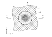
具体的には、ステップS12にてマスク処理された検査画像(マスキング画像データ)における、現在のポケット番号C(例えばC=1)に対応するポケット部2に係るポケット枠W内の濃淡画像を、該ポケット部2に生じた濃淡模様K1(図10参照)として抽出する。
Specifically, in the inspection image (masking image data) masked in step S12, the shade image in the pocket frame W related to the
つまり、濃淡模様K1とは、各画素ごとに輝度情報(例えば0から255までの256階調のうちのいずれかの値)を有した二次元画像情報であり、ポケット部2の底部2a等の各位置(座標位置)における肉厚の違い(肉厚分布)と、そこを透過する電磁波の透過率等との関係から、ポケット部2の底部2a等に生じる濃淡の二次元分布を示す像(透過電磁波の強度分布像)に相当するものである。
That is, the shading pattern K1 is two-dimensional image information having luminance information (for example, a value of any of 256 gradations from 0 to 255) for each pixel, such as the bottom 2a of the
尚、本実施形態では、ポケット枠Wが、ポケット部2の開口周縁部(側部2bとフィルム平坦部3bとの連接部)に合わせて設定されているため、このステップS16にて取得される濃淡模様K1には、ポケット部2の底部2aのみならず、ポケット部2の側部2b、並びに、底部2a及び側部2bが交わるポケット部2の角部2cに係る濃淡模様も含まれることとなる。
In the present embodiment, the pocket frame W is set according to the opening peripheral edge portion (the connecting portion between the
また、濃淡模様K1のうち、底部2aに対応する範囲に関しては、概ね底部2aの肉厚分布に対応した濃淡分布(輝度分布)を有する濃淡模様が得られる。一方、側部2bや角部2cに対応する範囲に関しては、その輝度情報が、側部2b等の肉厚方向(X方向やY方向)に沿って透過した電磁波に対応したものではなく、その成形時延伸方向(Z方向)に沿って透過した電磁波に対応したものとなるため、側部2b等の肉厚とは関係の薄いものとなる。
Further, with respect to the range corresponding to the
続くステップS17において、検査制御部52は、ステップS16において抽出した濃淡模様K1に対し、所定の輝度閾値L(図11参照)に基づき二値化処理を行う。図11は、図10に示す濃淡模様K1のA−A’線に沿った各画素に係る輝度値を示すグラフである。
In the following step S17, the
具体的には、濃淡模様K1を構成する画素のうち、輝度閾値L以上の輝度を有する画素を「1(明部)」とし、輝度閾値L未満の輝度を有する画素を「0(暗部)」として変換する。 Specifically, among the pixels constituting the shade pattern K1, the pixel having the brightness equal to or higher than the luminance threshold L is defined as “1 (bright portion)”, and the pixel having the luminance less than the luminance threshold L is referred to as “0 (dark portion)”. Convert as.
これにより、本実施形態では、ポケット部2の底部2a等のうち、肉厚が薄く透過率の高い薄肉部位が「1(明部)」となって現れ、肉厚が厚く透過率の低い厚肉部位が「0(暗部)」となって現れた、図12に示すような二値模様K2が得られる。かかる二値模様K2は、濃淡模様K1を二値化処理した二値化画像データとして画像メモリ53に記憶される。
As a result, in the present embodiment, among the
つまり、二値模様K2とは、各画素ごとに明暗二値情報を有した二次元画像情報であり、ポケット部2の底部2a等における肉厚分布に基づいた明暗二値の二次元分布を示す像(二値分布像)に相当するものである。
That is, the binary pattern K2 is two-dimensional image information having light / dark binary information for each pixel, and shows a two-dimensional distribution of light / dark binary based on the wall thickness distribution at the bottom 2a of the
続くステップS18において、検査制御部52は塊処理を実行する。具体的には、ステップS17にて取得した二値模様K2における「0(暗部)」及び「1(明部)」についてそれぞれ連結成分を特定する。
In the following step S18, the
これにより、ポケット部2が良品である場合の二値模様K2においては、図12に示すように、ポケット部2の底部2aの中心部付近に位置する「0(暗部)」の連接成分からなる略円形状の中央暗部領域E1と、その周りを囲むように位置する「1(明部)」の連接成分からなる略円環状の明部領域E2と、さらにその外側を囲むように位置する「0(暗部)」の連接成分からなる略円環状の外側暗部領域E3とが得られる。
As a result, in the binary pattern K2 when the
ここで、中央暗部領域E1はポケット部2の底部2aにおける厚肉領域に対応し、明部領域E2はポケット部2の底部2aにおける薄肉領域に対応し、外側暗部E3はポケット部2の側部2b及び角部2cに対応したものである。従って、明部領域E2が本実施形態における明部模様(明部分布像)に相当し、中央暗部領域E1や外側暗部領域E3が暗部模様(暗部分布像)に相当する。
Here, the central dark region E1 corresponds to the thick region in the bottom 2a of the
続くステップS19において、検査制御部52は、中央暗部領域E1と明部領域E2との境界部である、明部領域E2の内側境界部R1の位置が、予め設定された所定の判定基準を満たすか否か(所定の許容範囲内にあるか否か)を判定する。尚、かかる判定基準は、後述するティーチングモードにより予め取得され、判定用メモリ55に設定記憶されている。
In the following step S19, in the
具体的には、図13に示すように、内側境界部R1の周方向全域の各点(各座標位置)がそれぞれ内側境界最小値R1minよりもポケット径方向外側領域(ポケット中心位置から遠い側)に位置し、かつ、内側境界最大値R1maxよりもポケット径方向内側領域(ポケット中心位置に近い側)に位置しているか否かを判定する。ここで肯定判定された場合にはステップS20へ移行し、否定判定された場合には、現在のポケット番号Cに対応するポケット部2が不良品であるとみなし、そのままステップS22へ移行する。
Specifically, as shown in FIG. 13, each point (each coordinate position) in the entire circumferential direction of the inner boundary portion R1 is the outer region in the pocket radial direction (the side farther from the pocket center position) than the inner boundary minimum value R1min. It is determined whether or not the pocket is located in the inner region in the pocket radial direction (the side closer to the pocket center position) than the inner boundary maximum value R1max. If an affirmative determination is made here, the process proceeds to step S20, and if a negative determination is made, the
ステップS20において、検査制御部52は、明部領域E2と外側暗部E3との境界部である、明部領域E2の外側境界部R2の位置が、予め設定された所定の判定基準を満たすか否か(所定の許容範囲内にあるか否か)を判定する。上記同様、かかる判定基準は、後述するティーチングモードにより予め取得され、判定用メモリ55に設定記憶されている。
In step S20, the
具体的には、図13に示すように、外側境界部R2の周方向全域の各点(各座標位置)がそれぞれ外側境界最小値R2minよりもポケット径方向外側領域(ポケット中心位置から遠い側)に位置し、かつ、外側境界最大値R2maxよりもポケット径方向内側領域(ポケット中心位置に近い側)に位置しているか否かを判定する。ここで肯定判定された場合にはステップS21へ移行し、否定判定された場合には、現在のポケット番号Cに対応するポケット部2が不良品であるとみなし、そのままステップS22へ移行する。
Specifically, as shown in FIG. 13, each point (each coordinate position) in the entire circumferential direction of the outer boundary portion R2 is the outer region in the pocket radial direction (the side farther from the pocket center position) than the outer boundary minimum value R2min. It is determined whether or not the pocket is located in the inner region in the pocket radial direction (the side closer to the pocket center position) than the outer boundary maximum value R2max. If an affirmative determination is made here, the process proceeds to step S21, and if a negative determination is made, the
ステップS21において、検査制御部52は、現在のポケット番号Cに対応するポケット部2が良品であるとみなし、該ポケット番号Cに対応したポケット良品フラグの値に「1」を設定し、ステップS22へ移行する。
In step S21, the
つまり、本実施形態では、明部領域E2の内側境界部R1(中央暗部領域E1と明部領域E2との境界部)の位置が判定基準からポケット径方向内側領域へもポケット径方向外側領域へもはみだしておらず、かつ、明部領域E2の外側境界部R2(明部領域E2と外側暗部E3との境界部)の位置が判定基準からポケット径方向内側領域へもポケット径方向外側領域へもはみだしておらず、底部2aにおいて中央暗部領域E1や明部領域E2が適正な二次元形状で成形されている場合には、底部2aの成形状態(肉厚分布状態)が適正であると判定できると共に、側部2bや角部2cの成形状態(肉厚分布状態)に関しても適正であると推定できるため、これをもって、ポケット部2の成形状態が適正であると判定する。
That is, in the present embodiment, the position of the inner boundary portion R1 (the boundary portion between the central dark portion region E1 and the bright portion region E2) of the bright portion region E2 is changed from the determination criterion to the inner region in the pocket radial direction and the outer region in the pocket radial direction. The position of the outer boundary portion R2 (the boundary portion between the bright portion region E2 and the outer dark portion E3) of the bright portion region E2 does not protrude from the judgment standard to the pocket radial inner region and the pocket radial outer region. If the central dark region E1 and the bright region E2 are molded in an appropriate two-dimensional shape at the bottom 2a without protruding, it is determined that the molding state (thickness distribution state) of the bottom 2a is appropriate. At the same time, it can be estimated that the molding state (thickness distribution state) of the
従って、ポケット部2の成形状態に関する上記ステップS19、S20の良否判定処理(良否判定工程)を実行する機能により、本実施形態における良否判定手段が構成されることとなる。
Therefore, the pass / fail determination means in the present embodiment is configured by the function of executing the pass / fail determination process (pass / fail determination step) in steps S19 and S20 regarding the molding state of the
その後、検査制御部52は、ステップS22において現在のポケット番号Cに「1」を加えた後、ステップS15へ戻る。
After that, the
ここで、新たに設定したポケット番号Cが未だポケット数N(本実施形態では「10」)以下である場合には、再度ステップS16へ移行し、上記一連の処理を繰り返し実行する。 Here, if the newly set pocket number C is still less than or equal to the number of pockets N (“10” in this embodiment), the process proceeds to step S16 again, and the above series of processes is repeatedly executed.
一方、新たに設定したポケット番号Cがポケット数Nを超えたと判定された場合には、すべてのポケット部2に関する良否判定処理が終了したとみなし、ステップS23へ移行する。
On the other hand, when it is determined that the newly set pocket number C exceeds the number of pockets N, it is considered that the quality determination processing for all the
ステップS23において、検査制御部52は、検査範囲内の全ポケット部2のポケット良品フラグの値が「1」であるか否かを判定する。これにより、該検査範囲に対応するPTPシート1が良品であるか、不良品であるか判定する。
In step S23, the
ここで肯定判定された場合、すなわち検査範囲内のすべてのポケット部2が「良品」で、「不良品」判定されたポケット部2が1つも存在しない場合には、ステップS24において、該検査範囲に対応するPTPシート1を「良品」と判定し、本検査ルーチンを終了する。
If an affirmative determination is made here, that is, if all the
一方、ステップS23において否定判定された場合、すなわち検査範囲内に「不良品」判定されたポケット部2が1つでも存在する場合には、ステップS25において、該検査範囲に対応するPTPシート1を「不良品」と判定し、本検査ルーチンを終了する。
On the other hand, if a negative determination is made in step S23, that is, if even one
尚、ステップS24の良品判定処理、及び、ステップS25の不良品判定処理において、検査制御部52は、該検査範囲に対応するPTPシート1に関する検査結果を算出結果記憶装置54に記憶すると共に、充填制御装置82に出力する。
In the non-defective product determination process in step S24 and the defective product determination process in step S25, the
次に上記ポケット部検査に用いる判定基準を事前に取得し設定するティーチングモードについて説明する。 Next, a teaching mode in which the determination criteria used for the pocket portion inspection are acquired and set in advance will be described.
具体的には、内側境界部R1の良否判定を行う際に用いられる内側境界最小値R1min及び内側境界最大値R1max、並びに、外側境界部R2の良否判定を行う際に用いられる外側境界最小値R2min及び外側境界最大値R2maxを取得し設定する。 Specifically, the inner boundary minimum value R1min and the inner boundary maximum value R1max used when determining the quality of the inner boundary portion R1, and the outer boundary minimum value R2min used when determining the quality of the outer boundary portion R2. And the outer boundary maximum value R2max is acquired and set.
ティーチングモードにおいては、まず予め用意した良品の容器フィルム3(良品のポケット部2が成形された容器フィルム3)をカメラ51により撮像し、上記検査ルーチンと同様の過程を経て、良品のポケット部2に生じた濃淡模様K1を抽出する。
In the teaching mode, first, a good-quality container film 3 (a
その後、この良品の濃淡模様K1に対し二値化処理を実行し、良品の二値模様K2を取得すると共に、これに対し塊処理を実行し、良品のポケット部2の底部2aに係る中央暗部領域E1、明部領域E2及び外側暗部領域E3を取得する。 After that, a binarization process is executed on the light and shade pattern K1 of the good product to acquire the binary pattern K2 of the good product, and a lump process is executed on the binary pattern K2 of the good product. The region E1, the bright region E2, and the outer dark region E3 are acquired.
そして、ポケット部2の底部2aの中心位置を基準にして、明部領域E2を所定量だけ拡大し、該拡大された明部領域E2の内側境界部R1を内側境界最大値R1maxとして判定用メモリ55に設定すると共に、該拡大された明部領域E2の外側境界部R2を外側境界最大値R2maxとして判定用メモリ55に設定する。
Then, with reference to the center position of the
次に、ポケット部2の底部2aの中心位置を基準にして、明部領域E2を所定量だけ縮小し、該縮小された明部領域E2の内側境界部R1を内側境界最小値R1minとして判定用メモリ55に設定すると共に、該縮小された明部領域E2の外側境界部R2を外側境界最小値R2minとして判定用メモリ55に設定する。これにより、本ティーチングモードを終了する。
Next, the bright region E2 is reduced by a predetermined amount with reference to the center position of the bottom 2a of the
尚、判定基準の取得方法は、上記構成に限られるものではなく、他の方法を採用してもよい。例えば、以下のように判定基準を取得するようにしてもよい。 The method for acquiring the determination criteria is not limited to the above configuration, and other methods may be adopted. For example, the determination criteria may be acquired as follows.
まず明部領域E2のポケット径方向中央部を基準にして、明部領域E2を所定量だけポケット径方向に膨張させ、該膨張させた明部領域E2の内側境界部R1を内側境界最小値R1minとして判定用メモリ55に設定すると共に、該膨張させた明部領域E2の外側境界部R2を外側境界最大値R2maxとして判定用メモリ55に設定する。
First, the bright region E2 is expanded in the pocket radial direction by a predetermined amount with reference to the central portion in the pocket radial direction of the bright region E2, and the inner boundary portion R1 of the expanded bright region E2 is set to the inner boundary minimum value R1min. Is set in the
次に、明部領域E2のポケット径方向中央部を基準にして、明部領域E2を所定量だけポケット径方向に収縮させ、該収縮させた明部領域E2の内側境界部R1を内側境界最大値R1maxとして判定用メモリ55に設定すると共に、該収縮させた明部領域E2の外側境界部R2を外側境界最小値R2minとして判定用メモリ55に設定する。
Next, the bright region E2 is contracted in the pocket radial direction by a predetermined amount with reference to the central portion in the pocket radial direction of the bright region E2, and the inner boundary portion R1 of the contracted bright region E2 is set to the inner boundary maximum. The value R1max is set in the
以上詳述したように、本実施形態によれば、ポケット部2の成形された容器フィルム3の搬送が一旦停止するインターバル毎に、該容器フィルム3に対し照明装置50から電磁波が照射されると共に、該容器フィルム3を透過した電磁波(紫外光)をカメラ51により撮像し、取得された透過画像データから、ポケット部2の底部2aに生じた濃淡模様K1を抽出し、これを所定の判定基準と比較することにより、ポケット部2の成形状態に関する良否判定を行う構成となっている。
As described in detail above, according to the present embodiment, the electromagnetic wave is irradiated from the
かかる構成により、ポケット部2の底部2aの成形状態(肉厚分布状態)に関する良否判定は勿論のこと、ポケット部2の側部2bや角部2cの成形状態(肉厚分布状態)に関する良否判定を行うことも可能となり、ポケット部2の側部2b等における肉厚分布の偏りの有無など、ポケット部2の側部2b等の成形不良(肉厚不良)をより精度良く検出することができる。
With this configuration, not only the quality judgment regarding the molding state (thickness distribution state) of the
また、本実施形態では、ポケット部2の底部2aを撮像する1回の撮像で側部2b全周の成形状態を把握することが可能となるため、検査の高速化、ひいてはブリスターパックの生産性の向上を図ることができる。
Further, in the present embodiment, since it is possible to grasp the molding state of the entire circumference of the
さらに、本実施形態では、透光性を有する容器フィルムに対し、電磁波として、容器フィルム3の透過率がおよそ30±10パーセントとなる波長253±20nmの紫外光を用いて検査を行う構成となっている。紫外光は、可視光に比べて透過率が低く、透光性を有する容器フィルム3を透過しにくいため、ポケット部2の成形状態に関する検査をより適切に行うことができる。また、ポケット部2の底部2aの薄肉部位と厚肉部位における光の透過率に差が生じやすくなり、検査をより適切に行うことができる。
Further, in the present embodiment, the translucent container film is inspected by using ultraviolet light having a wavelength of 253 ± 20 nm, which makes the transmittance of the
加えて、本実施形態では、ポケット部検査に用いる判定基準を事前にティーチングモードにおいて、カメラ51により良品のポケット部2を撮像して得られた濃淡模様Kに基づいて定めている。これにより、ポケット部2の底部2aの形状や肉厚分布が複雑である場合であっても、比較的容易に判定基準を設定することができる。
In addition, in the present embodiment, the determination criteria used for the pocket portion inspection are determined in advance based on the shade pattern K obtained by imaging the
〔第2実施形態〕
次に第2実施形態について図14を参照して詳しく説明する。図14は、本実施形態におけるポケット部検査の流れを示すフローチャートである。尚、上述した第1実施形態と重複する部分については、同一の部材名称、同一の符号を用いる等してその詳細な説明を省略するとともに、以下には第1実施形態と相違する部分を中心として説明することとする。
[Second Embodiment]
Next, the second embodiment will be described in detail with reference to FIG. FIG. 14 is a flowchart showing the flow of pocket portion inspection in the present embodiment. Regarding the parts that overlap with the first embodiment described above, detailed description thereof will be omitted by using the same member names and the same reference numerals, and the parts different from the first embodiment will be mainly described below. It will be explained as.
ポケット部成形装置16によってポケット部2の成形された容器フィルム3の所定範囲がポケット部検査装置21に一旦停止すると、検査制御部52は、まず容器フィルム3の所定範囲に対し照明装置50から電磁波(紫外光)を照射する照射処理(照射工程)を実行すると共に、カメラ51による撮像処理(撮像工程)を実行する。
Once the predetermined range of the
そして、容器フィルム3の透過画像データが画像メモリ53に取り込まれると、検査制御部52は、まず検査画像取得処理を実行する(ステップT11)。尚、本処理は、第1実施形態のステップS11と同様の処理であるため、詳細な説明は省略する。
Then, when the transparent image data of the
検査画像が取得されると、検査制御部52は、続くステップT12においてマスク処理を実行する。尚、本処理は、第1実施形態のステップS12と同様の処理であるため、詳細な説明は省略する。
When the inspection image is acquired, the
次に、検査制御部52は、ステップT13において、全ポケット部2のポケット良品フラグの値に「0」に設定し、続くステップT14において、算出結果記憶装置54に設定されたポケット番号カウンタの値Cに初期値である「1」を設定する。
Next, in step T13, the
そして、検査制御部52は、ステップT15において、ポケット番号Cが一検査範囲あたりのポケット数N以下であるか否かを判定する。ここで肯定判定された場合にはステップT16へ移行し、検査制御部52は、現在のポケット番号Cのポケット部2に係る濃淡模様を抽出する濃淡模様抽出処理(濃淡模様抽出工程)を実行する。尚、本処理は、第1実施形態のステップS16と同様の処理であるため、詳細な説明は省略する。
Then, in step T15, the
続くステップT17において、検査制御部52は不良領域特定処理を実行する。本実施形態では、まずステップT16において抽出した濃淡模様K1の各画素の輝度値が、該画素毎に予め設定された所定の判定基準を満たすか否か(所定の許容範囲内にあるか否か)を判定し、該判定基準から外れた画素を不良領域として特定する。
In the following step T17, the
具体的には、図15に示すように、濃淡模様K1の各画素の輝度値がそれぞれ該画素に係る輝度上限値Hmaxよりも小さく、かつ、該画素に係る輝度下限値Hminよりも大きいか否かを判定する。かかる判定基準(輝度上限値Hmax及び輝度下限値Hmin)は、後述するティーチングモードにより予め取得され、判定用メモリ55に設定記憶されている。
Specifically, as shown in FIG. 15, whether or not the brightness value of each pixel of the shade pattern K1 is smaller than the brightness upper limit value Hmax related to the pixel and larger than the brightness lower limit value Hmin related to the pixel. Is determined. Such determination criteria (luminance upper limit value Hmax and luminance lower limit value Hmin) are acquired in advance by the teaching mode described later, and are set and stored in the
尚、図15は、図10に示す濃淡模様K1のA−A’線に沿った各画素に係る輝度値H、並びに、A−A’線に沿った各画素に係る輝度上限値Hmax及び輝度下限値Hminを示したグラフである。 In addition, FIG. 15 shows the brightness value H related to each pixel along the AA'line of the shading pattern K1 shown in FIG. 10, and the brightness upper limit value Hmax and the brightness related to each pixel along the AA' line. It is a graph which showed the lower limit value Hmin.
そして、検査制御部52は、図16に示すように、濃淡模様K1を構成する画素のうち、判定基準(輝度上限値Hmax及び輝度下限値Hmin)内に収まった画素を「1(明部)」とし、判定基準から外れ不良領域として特定された画素を「0(暗部)」として表した判定用画像Jを取得する。
Then, as shown in FIG. 16, the
続くステップT18において、検査制御部52は塊処理を実行する。具体的には、ステップT17にて取得した「0(暗部)」及び「1(明部)」についてそれぞれの連結成分を特定すると共に、不良領域として特定された「0(暗部)」の連結成分の面積値Pの合計値である総不良面積Pxを取得する。
In the following step T18, the
そして、ステップT19において、検査制御部52は、ステップT18にて算出した総不良面積Pxが予め設定した判定基準Po以下であるか否かを判定する。つまり、総不良面積Pxが許容範囲内であるか否かを判定することにより、該ポケット部2の成形状態に関する良否判定を行う。従って、かかるステップT19の良否判定処理(良否判定工程)を実行する機能により、本実施形態における良否判定手段が構成されることとなる。
Then, in step T19, the
これに限らず、ここで、例えば不良領域として特定された「0(暗部)」の連結成分のうち、最大面積のものが許容範囲内にあるか否かを判定する方法や、「0(暗部)」の連結成分のばらつき度合い(分布状況)を判定する方法など、他の方法により良否判定を行う構成としてもよい。勿論、その大小に関係なく、不良領域が1箇所でも存在すれば、不良品判定する構成としてもよい。 Not limited to this, here, for example, a method of determining whether or not the maximum area of the connected components of "0 (dark area)" specified as a defective area is within the permissible range, or "0 (dark area)". ) ”Is a method of determining the degree of variation (distribution status) of the connected components, or other methods may be used to determine the quality. Of course, regardless of the size, if there is even one defective region, a defective product may be determined.
ステップT19において総不良面積Pxが判定基準Po以下であると肯定判定された場合にはステップT20へ移行する。一方、ここで否定判定された場合には、現在のポケット番号Cに対応するポケット部2が不良品であるとみなし、そのままステップT21へ移行する。
If it is determined in step T19 that the total defective area Px is equal to or less than the determination criterion Po, the process proceeds to step T20. On the other hand, if a negative determination is made here, the
ステップT20において、検査制御部52は、現在のポケット番号Cに対応するポケット部2が良品であるとみなし、該ポケット番号Cに対応したポケット良品フラグの値に「1」を設定し、ステップT21へ移行する。
In step T20, the
ステップT21において、検査制御部52は、現在のポケット番号Cに「1」を加えた後、ステップT15へ戻る。
In step T21, the
ここで、新たに設定したポケット番号Cが未だポケット数N以下である場合には、再度ステップT16へ移行し、上記一連の処理を繰り返し実行する。 Here, if the newly set pocket number C is still the number of pockets N or less, the process proceeds to step T16 again, and the above series of processes are repeatedly executed.
一方、新たに設定したポケット番号Cがポケット数Nを超えたと判定された場合には、すべてのポケット部2に関する良否判定処理が終了したとみなし、ステップT22へ移行する。
On the other hand, when it is determined that the newly set pocket number C exceeds the number of pockets N, it is considered that the quality determination processing for all the
ステップT22において、検査制御部52は、検査範囲内の全ポケット部2のポケット良品フラグの値が「1」であるか否かを判定する。これにより、該検査範囲に対応するPTPシート1が良品であるか、不良品であるか判定する。
In step T22, the
ここで肯定判定された場合、すなわち検査範囲内のすべてのポケット部2が「良品」で、「不良品」判定されたポケット部2が1つも存在しない場合には、ステップT23において、該検査範囲に対応するPTPシート1を「良品」と判定し、本検査ルーチンを終了する。
If an affirmative determination is made here, that is, if all the
一方、ステップT22において否定判定された場合、すなわち検査範囲内に「不良品」判定されたポケット部2が1つでも存在する場合には、ステップT24において、該検査範囲に対応するPTPシート1を「不良品」と判定し、本検査ルーチンを終了する。
On the other hand, if a negative determination is made in step T22, that is, if there is at least one
次に本実施形態におけるティーチングモードについて説明する。具体的には、濃淡模様K1を構成する各画素の良否判定を行う際に用いられる輝度上限値Hmax及び輝度下限値Hminを取得し設定する。 Next, the teaching mode in this embodiment will be described. Specifically, the brightness upper limit value Hmax and the brightness lower limit value Hmin used when determining the quality of each pixel constituting the shading pattern K1 are acquired and set.
ティーチングモードにおいては、予め用意した良品の容器フィルム3(10個の良品のポケット部2が成形された容器フィルム3)をカメラ51により撮像し、上記検査ルーチンと同様の過程を経て、10個の良品のポケット部2に生じた濃淡模様K1を抽出する。
In the teaching mode, a good container film 3 (a
その後、画素ごとに、10個の良品の濃淡模様K1の各画素の輝度値の平均値である平均輝度値を算出する。続いて、画素ごとに、平均輝度値に対し所定のオフセット値αを加算した値を輝度上限値Hmaxとして判定用メモリ55に設定する。同様に、画素ごとに、平均輝度値から所定のオフセット値αを減算した値を輝度下限値Hminとして判定用メモリ55に設定する。これにより、本ティーチングモードを終了する。
After that, the average luminance value, which is the average value of the luminance values of each pixel of the 10 non-defective shade patterns K1 for each pixel, is calculated. Subsequently, for each pixel, a value obtained by adding a predetermined offset value α to the average luminance value is set in the
以上詳述したように、本実施形態によれば、ポケット部2の成形状態に関し、より細やかな検査を行うことができ、ポケット部2の成形不良をより精度良く検出することができる。
As described in detail above, according to the present embodiment, it is possible to perform a more detailed inspection on the molding state of the
尚、上記各実施形態の記載内容に限定されず、例えば次のように実施してもよい。勿論、以下において例示しない他の応用例、変更例も当然可能である。 The content is not limited to the description of each of the above embodiments, and may be implemented as follows, for example. Of course, other application examples and modification examples not illustrated below are also possible.
(a)検査対象となるブリスターパックの構成は、上記各実施形態に限定されるものではない。例えば上記各実施形態では、ブリスターパックとして、錠剤5等の内容物を収容するPTPシート1が例示されている。
(A) The configuration of the blister pack to be inspected is not limited to each of the above embodiments. For example, in each of the above embodiments, as a blister pack, a
これに限らず、例えば容器フィルムからカバーフィルムを引き剥がして内容物を取出すピールオープン式のブリスターパック(食料品等を収容するポーションパックなど)や、電子部品等の内容物を収容し搬送するブリスターパック(キャリアテープなど)、容器フィルムに対しカバーフィルムが取着されず台紙等が組み付けられるタイプのブリスターパックなど、各種ブリスターパックを検査対象とすることができる。 Not limited to this, for example, a peel-open type blister pack (such as a portion pack for storing foodstuffs) that peels off the cover film from the container film to take out the contents, and a blister that stores and transports the contents such as electronic parts. Various blister packs can be inspected, such as packs (carrier tapes, etc.) and blister packs of the type in which the cover film is not attached to the container film and the mount etc. can be attached.
(b)容器フィルムにおけるポケット部の形状、大きさ、深さ、個数、配列など、ポケット部の構成は上記各実施形態に限定されるものではなく、内容物の種別や形状、用途などに応じて適宜選択することができる。例えばポケット部2の底部2aが平面視で略三角形状、略楕円形状、略四角形状、略菱形状等であってもよい。
(B) The configuration of the pocket portion, such as the shape, size, depth, number, and arrangement of the pocket portion in the container film, is not limited to each of the above embodiments, and depends on the type, shape, and use of the contents. Can be selected as appropriate. For example, the
より具体的に、例えば図17(a),(b)に示すようなブリスターパック100を検査対象とすることもできる。ブリスターパック100は、ポケット部101を有している。ポケット部101は、平面視矩形状の底部101aと、該底部101aの周囲に連接した矩形枠状の側部101bとから構成されている。ポケット部101の底部101aには、ポケット内側に向け膨出した複数の膨出リブ101cが形成されている。
More specifically, for example, the
このようなポケット部101について、上記第1実施形態の検査手順に則して、底部101aに生じる濃淡画像を抽出し(ステップS16)、二値化処理(ステップS17)及び塊処理(ステップS18)を行った場合には、図17(c)に示すように、厚肉領域(膨出リブ101c)に対応した暗部領域E11と、薄肉領域(底部101a一般部)に対応した明部領域E12とが得られる。
With respect to such a
そして、暗部領域E11と明部領域E12との境界部である、明部領域E12の内側境界部R11が所定の判定基準(内側境界最小値R11min及び内側境界最大値R11max)を満たすか否かを判定すると共に、明部領域E12の外側境界部R12が所定の判定基準(外側境界最小値R12min及び外側境界最大値R12max)を満たすか否かを判定することにより、ポケット部101の成形状態に関する良否判定を行うことができる。
Then, whether or not the inner boundary portion R11 of the bright region E12, which is the boundary portion between the dark region E11 and the bright region E12, satisfies the predetermined determination criteria (inner boundary minimum value R11min and inner boundary maximum value R11max). By determining whether or not the outer boundary portion R12 of the bright region E12 satisfies the predetermined determination criteria (outer boundary minimum value R12min and outer boundary maximum value R12max), the quality of the molding state of the
(c)容器フィルムやカバーフィルムの材質や層構造等は、上記各実施形態に限定されるものではない。例えば上記各実施形態では、容器フィルム3がPPやPVC等の無色透明な熱可塑性樹脂材料により形成され、透光性を有している。
(C) The material, layer structure, and the like of the container film and the cover film are not limited to the above embodiments. For example, in each of the above embodiments, the
これに限らず、例えば容器フィルム3が無色半透明の樹脂材料や、有色透明又は有色半透明の樹脂材料は勿論のこと、不透明材料(不透明樹脂材料や金属材料など)により形成された構成としてもよい。金属材料としては、例えばアルミラミネートフィルムなど、アルミニウムを主材料としたものなどが一例に挙げられる。
Not limited to this, for example, the
尚、不透明材料により形成された容器フィルム3に関しては、後述するように、例えばX線など、不透明材料を透過可能な電磁波を照明装置50から照射することにより、検査可能となる。
The
(d)ポケット部の成形方法は上記各実施形態に限定されるものではない。例えば上記各実施形態では、プラグアシスト圧空成形法によりポケット部2が成形される構成となっている。
(D) The molding method of the pocket portion is not limited to each of the above embodiments. For example, in each of the above embodiments, the
これに代えて、例えば真空成形法、圧空成形法、プラグ成形法など、平坦な容器フィルム3の一部(成形予定部3a)を部分的に加熱軟化させ延伸加工する公知の各種成形方法を採用することができる。
Instead of this, various known molding methods such as a vacuum forming method, a compressed air forming method, and a plug forming method are adopted, in which a part of the flat container film 3 (scheduled
但し、容器フィルムがアルミラミネートフィルムの場合には、加熱することにより接着層間にて剥離が生じて成形時に破れてしまう可能性があるため、事前に加熱を行わない冷間成形(コールドフォーミング)が適している。かかる場合においても、ポケット成形時には、例えば挟持部分近傍などが引き伸ばされやすく、容器フィルムが必ずしも均一には延伸されないため、ポケット部の各部の肉厚に偏りが生じるおそれがある。 However, when the container film is an aluminum laminated film, it may be peeled off between the bonding layers due to heating and may be torn during molding. Therefore, cold molding without heating in advance is performed. Is suitable. Even in such a case, during pocket molding, for example, the vicinity of the sandwiched portion is likely to be stretched, and the container film is not necessarily stretched uniformly, so that the wall thickness of each portion of the pocket portion may be biased.
(e)照射手段及び撮像手段の構成は、上記実施形態に限定されるものではない。例えば上記各実施形態では、照明装置50がポケット部2の突出側に配置され、カメラ51がポケット部2の開口側に配置された構成となっているが、両者の位置関係が逆になった構成としてもよい。
(E) The configuration of the irradiation means and the imaging means is not limited to the above embodiment. For example, in each of the above embodiments, the
また、上記各実施形態において、照明装置50は、紫外光を含む電磁波を照射するように構成されているが、容器フィルム3の材質や色などに応じて、照明装置50から照射される電磁波の波長を適宜変更してもよい。勿論、ここでバンドパスフィルタ51aを省略し、照明装置50から照射され容器フィルム3を透過した電磁波が直接カメラ51に入射する構成としてもよい。
Further, in each of the above embodiments, the
例えば容器フィルム3がアルミニウム等からなる不透明材料によって構成されている場合には、照明装置50からX線を照射することとしてもよい。また、容器フィルム3が色の付いた半透明材料によって構成される場合には、照明装置50から白色光などの可視光を照射してもよい。
For example, when the
(f)上記各実施形態では、容器フィルム3の透過率がおよそ30±10パーセントとなる波長253±20nmの紫外光が検査に用いられる構成となっているが、これとは異なる波長の電磁波を用いて検査を行う構成としてもよい。
(F) In each of the above embodiments, ultraviolet light having a wavelength of 253 ± 20 nm having a transmittance of about 30 ± 10% of the
但し、容器フィルム3を透過する電磁波の透過率が高すぎても低すぎても、ポケット部2の底部2aの薄肉部位と厚肉部位における光の透過率に差が生じにくくなるおそれがあるため、容器フィルム3の透過率が15パーセント以上かつ60パーセント以下となる波長の電磁波、より好ましくは、容器フィルムの透過率が20パーセント以上かつ50パーセント以下となる波長の電磁波を用いることが好ましい。
However, if the transmittance of the electromagnetic wave transmitted through the
(g)ポケット部の底部等に生じる濃淡模様に関する良否判定方法は、上記実施形態に限定されるものではない。 (G) The quality determination method for the shading pattern generated on the bottom of the pocket portion or the like is not limited to the above embodiment.
例えば上記第1実施形態では、濃淡模様K1を二値化した二値模様K2を基に、明部領域E2等の形成範囲が適正であるか否かを判定することで、ポケット部2の成形状態に関する良否判定を行う構成となっている。
For example, in the first embodiment, the
これに限らず、例えば濃淡模様K1に対し微分処理等を行い、明部領域E2等の輪郭部を抽出し、明部領域E2等の形成範囲が適正であるか否かを判定することで良否判定を行う構成としてもよい。 Not limited to this, for example, it is good or bad by performing differential processing or the like on the shading pattern K1, extracting the contour portion such as the bright region E2, and determining whether or not the formation range of the bright region E2 or the like is appropriate. It may be configured to make a determination.
また、例えば検査対象となるポケット部2の底部2aに生じる濃淡模様と、予め取得した良品のポケット部2の底部2aに生じた濃淡模様とをパターンマッチング等の手法により比較し、その一致度により良否判定を行う構成としてもよい。
Further, for example, the shading pattern generated on the bottom 2a of the
(h)上記各実施形態では、カメラ51により良品のポケット部2を撮像して得られた濃淡模様K1を基に、良否判定に用いられる判定基準が定められる構成となっている。これに限らず、ポケット部2の設計データ等に基づいて判定基準を算出し設定する構成としてもよい。
(H) In each of the above embodiments, the determination criteria used for the quality determination are determined based on the shade pattern K1 obtained by photographing the
(i)上記各実施形態では、錠剤5等の内容物の充填まで行うPTP包装機(ブリスター包装機)11内に、ポケット部検査装置21を配置した構成となっている。これに限らず、例えば容器フィルム3の製造と、内容物の包装とを別々に行う製造ラインなどにおいては、容器フィルム3の製造装置にポケット部検査装置21を備えた構成としてもよい。また、容器フィルム3の製造装置とは別にオフラインで、ポケット部2の成形された容器フィルム3を検査する検査装置を備えた構成としてもよい。
(I) In each of the above embodiments, the pocket
1…PTPシート、2…ポケット部、2a…底部、2b…側部、2c…角部、3…容器フィルム、4…カバーフィルム、5…錠剤、11…PTP包装機、15…加熱装置、16…ポケット部成形装置、21…ポケット部検査装置、50…照明装置、51…カメラ、52…検査制御部、53…画像メモリ、54…算出結果記憶装置、55…判定用メモリ、C…ポケット番号、E1…中央暗部領域、E2…明部領域、E3…外側暗部領域、L…輝度閾値、K1…濃淡模様、K2…二値模様、R1…内側境界部、R1min…内側境界最小値、R1max…内側境界最大値、R2…外側境界部、R2min…外側境界最小値、R2max…外側境界最大値、W…ポケット枠。 1 ... PTP sheet, 2 ... pocket part, 2a ... bottom part, 2b ... side part, 2c ... corner part, 3 ... container film, 4 ... cover film, 5 ... tablet, 11 ... PTP packaging machine, 15 ... heating device, 16 ... Pocket molding device, 21 ... Pocket inspection device, 50 ... Lighting device, 51 ... Camera, 52 ... Inspection control unit, 53 ... Image memory, 54 ... Calculation result storage device, 55 ... Judgment memory, C ... Pocket number , E1 ... central dark area, E2 ... bright area, E3 ... outer dark area, L ... brightness threshold, K1 ... shade pattern, K2 ... binary pattern, R1 ... inner boundary, R1min ... inner boundary minimum, R1max ... Inner boundary maximum value, R2 ... outer boundary, R2min ... outer boundary minimum value, R2max ... outer boundary maximum value, W ... pocket frame.
Claims (10)
前記ポケット部が成形された容器フィルムに対し所定の電磁波を照射可能な照射手段と、
前記容器フィルムを介して前記照射手段とは反対側に設けられ、少なくとも前記ポケット部の底部を透過した前記電磁波を撮像し画像データを取得可能な撮像手段と、
前記撮像手段により取得された画像データを基に、前記電磁波の照射により前記ポケット部の底部に生じる濃淡模様を抽出可能な濃淡模様抽出手段と、
前記濃淡模様抽出手段により抽出された濃淡模様を、予め設定された所定の判定基準と比較することにより、少なくとも前記ポケット部の側部の成形状態に関する良否判定を実行可能な良否判定手段とを備えたことを特徴とする検査装置。 An inspection device for inspecting the molding condition of the pocket of a blister pack.
An irradiation means capable of irradiating a container film on which the pocket portion is formed with a predetermined electromagnetic wave,
An imaging means provided on the side opposite to the irradiation means via the container film and capable of capturing at least the electromagnetic wave transmitted through the bottom of the pocket portion and acquiring image data.
Based on the image data acquired by the imaging means, a shade pattern extraction means capable of extracting a shade pattern generated at the bottom of the pocket portion by irradiation with the electromagnetic wave, and a shade pattern extraction means.
By comparing the shading pattern extracted by the shading pattern extracting means with a predetermined determination standard set in advance, it is provided with a pass / fail determining means capable of performing a pass / fail judgment regarding at least the molding state of the side portion of the pocket portion. An inspection device characterized by the fact that.
前記濃淡模様を所定の閾値で二値化した上で、これにより得られた二値模様のうち、前記閾値以上となる明部の連結成分である明部模様又は前記閾値未満となる暗部の連結成分である暗部模様を、所定の判定基準と比較することにより、前記良否判定を実行することを特徴とする請求項1に記載の検査装置。 The pass / fail determination means
After binarizing the shading pattern with a predetermined threshold value, among the binary patterns obtained by this, the bright part pattern which is a connecting component of the bright part which is equal to or more than the threshold value or the dark part which is less than the threshold value is connected. The inspection device according to claim 1, wherein the quality determination is executed by comparing the dark portion pattern, which is a component, with a predetermined determination criterion.
前記明部模様又は前記暗部模様の境界部の位置が、所定の判定基準を満たすか否かを判定することにより、前記良否判定を行うことを特徴とする請求項2に記載の検査装置。 The pass / fail determination means
The inspection device according to claim 2, wherein the quality determination is performed by determining whether or not the position of the boundary portion of the bright portion pattern or the dark portion pattern satisfies a predetermined determination criterion.
前記濃淡模様を構成する各画素における輝度がそれぞれ所定の判定基準を満たすか否かを判定し、該判定基準を満たさない画素を不良領域として把握した上で、該不良領域が所定の判定基準を満たすか否かを判定することにより、前記良否判定を行うことを特徴とする請求項1に記載の検査装置。 The pass / fail determination means
After determining whether or not the brightness of each pixel constituting the shading pattern satisfies a predetermined determination criterion and grasping the pixel that does not satisfy the determination criterion as a defective region, the defective region determines a predetermined determination criterion. The inspection device according to claim 1, wherein the quality determination is performed by determining whether or not the condition is satisfied.
前記照射手段は、前記電磁波として紫外光を照射可能に構成されていることを特徴とする請求項1乃至4のいずれかに記載の検査装置。 The container film is made of a translucent resin film material.
The inspection device according to any one of claims 1 to 4, wherein the irradiation means is configured to be capable of irradiating ultraviolet light as the electromagnetic wave.
前記撮像手段により良品のポケット部を撮像して得られた前記濃淡模様に基づいて定められることを特徴とする請求項1乃至6のいずれかに記載の検査装置。 The criterion is
The inspection device according to any one of claims 1 to 6, wherein the inspection apparatus is determined based on the shading pattern obtained by imaging a non-defective pocket portion with the imaging means.
帯状に搬送される前記容器フィルムに対し前記ポケット部を成形するポケット部成形工程と、
前記ポケット部に前記内容物を充填する充填工程と、
前記ポケット部に前記内容物が充填された前記容器フィルムに対し、前記ポケット部を塞ぐようにして帯状の前記カバーフィルムを取着する取着工程と、
前記容器フィルムに前記カバーフィルムが取着された帯状体から前記ブリスターパックを切離す切離工程と、
前記ブリスターパックのポケット部の成形状態を検査する検査工程とを備え、
前記検査工程において、
前記ポケット部が成形された容器フィルムに対し所定の電磁波を照射する照射工程と、
少なくとも前記ポケット部の底部を透過した前記電磁波を撮像し画像データを取得する撮像工程と、
前記撮像により取得された画像データを基に、前記電磁波の照射により前記ポケット部の底部に生じる濃淡模様を抽出する濃淡模様抽出工程と、
前記抽出された濃淡模様を、予め設定された所定の判定基準と比較することにより、少なくとも前記ポケット部の側部の成形状態に関する良否判定を行う良否判定工程とを備えたことを特徴とするブリスターパックの製造方法。 A method for manufacturing a blister pack, wherein a predetermined content is housed in a pocket portion formed into a container film, and a cover film is attached so as to close the pocket portion.
A pocket portion molding step of molding the pocket portion on the container film conveyed in a strip shape,
A filling step of filling the pocket with the contents,
An attachment step of attaching the band-shaped cover film to the container film in which the pocket portion is filled with the contents so as to close the pocket portion.
A cutting step of separating the blister pack from the strip-shaped body to which the cover film is attached to the container film, and
It is provided with an inspection process for inspecting the molding state of the pocket portion of the blister pack.
In the inspection process
An irradiation step of irradiating a container film on which the pocket portion is formed with a predetermined electromagnetic wave, and
An imaging step of capturing at least the electromagnetic wave transmitted through the bottom of the pocket portion and acquiring image data,
Based on the image data acquired by the imaging, the shade pattern extraction step of extracting the shade pattern generated at the bottom of the pocket portion by the irradiation of the electromagnetic wave, and the shade pattern extraction step.
The blister is characterized by comprising a quality determination step of at least determining the quality of the molding state of the side portion of the pocket portion by comparing the extracted shade pattern with a predetermined determination standard set in advance. How to make a pack.
Priority Applications (6)
| Application Number | Priority Date | Filing Date | Title |
|---|---|---|---|
| JP2019038259A JP6777784B2 (en) | 2019-03-04 | 2019-03-04 | Manufacturing method for inspection equipment, blister packaging machines and blister packs |
| CN202080012428.1A CN113396108B (en) | 2019-03-04 | 2020-01-27 | Inspection device, blister packaging machine, and method for manufacturing blister bag |
| DE112020001058.9T DE112020001058T5 (en) | 2019-03-04 | 2020-01-27 | Testing device, blister packaging machine, and method for producing a blister packaging |
| PCT/JP2020/002742 WO2020179281A1 (en) | 2019-03-04 | 2020-01-27 | Inspection device, blister packing machine, and method of manufacturing blister pack |
| KR1020217015767A KR102547732B1 (en) | 2019-03-04 | 2020-01-27 | Manufacturing method of inspection device, blister packaging machine and blister pack |
| TW109103457A TWI729690B (en) | 2019-03-04 | 2020-02-05 | Inspection device, blister packaging machine and manufacturing method of blister box |
Applications Claiming Priority (1)
| Application Number | Priority Date | Filing Date | Title |
|---|---|---|---|
| JP2019038259A JP6777784B2 (en) | 2019-03-04 | 2019-03-04 | Manufacturing method for inspection equipment, blister packaging machines and blister packs |
Publications (2)
| Publication Number | Publication Date |
|---|---|
| JP2020143902A JP2020143902A (en) | 2020-09-10 |
| JP6777784B2 true JP6777784B2 (en) | 2020-10-28 |
Family
ID=72337524
Family Applications (1)
| Application Number | Title | Priority Date | Filing Date |
|---|---|---|---|
| JP2019038259A Active JP6777784B2 (en) | 2019-03-04 | 2019-03-04 | Manufacturing method for inspection equipment, blister packaging machines and blister packs |
Country Status (6)
| Country | Link |
|---|---|
| JP (1) | JP6777784B2 (en) |
| KR (1) | KR102547732B1 (en) |
| CN (1) | CN113396108B (en) |
| DE (1) | DE112020001058T5 (en) |
| TW (1) | TWI729690B (en) |
| WO (1) | WO2020179281A1 (en) |
Families Citing this family (5)
| Publication number | Priority date | Publication date | Assignee | Title |
|---|---|---|---|---|
| JP7241721B2 (en) * | 2020-08-04 | 2023-03-17 | Ckd株式会社 | Inspection device, blister packaging machine and blister pack manufacturing method |
| JP7433260B2 (en) * | 2021-02-15 | 2024-02-19 | Ckd株式会社 | Manufacturing method of PTP sheet |
| DE102021122541A1 (en) | 2021-08-31 | 2023-03-02 | Syntegon Packaging Solutions B.V. | Monitoring device, packaging machine with such a monitoring device and method for operating such a monitoring device |
| TWI814570B (en) * | 2022-09-06 | 2023-09-01 | 特騰綠的包材股份有限公司 | Convenience Sealer |
| JP7466613B1 (en) | 2022-11-25 | 2024-04-12 | Ckd株式会社 | Inspection equipment and blister packing machines |
Family Cites Families (16)
| Publication number | Priority date | Publication date | Assignee | Title |
|---|---|---|---|---|
| DE2638138C3 (en) * | 1976-08-25 | 1979-05-03 | Kloeckner-Werke Ag, 4100 Duisburg | Device for recognizing and sorting out defective packs that are transported along a conveyor line |
| JPH0618958U (en) * | 1992-08-19 | 1994-03-11 | 東芝エンジニアリング株式会社 | Foreign substance inspection device for PTP |
| JP3216876B2 (en) * | 1997-11-07 | 2001-10-09 | 株式会社之技術綜合 | Sheet packaging inspection device |
| JP3494561B2 (en) * | 1997-10-13 | 2004-02-09 | シーケーディ株式会社 | Tablet appearance inspection method and tablet appearance inspection device |
| JP2001147200A (en) | 1999-11-19 | 2001-05-29 | Hitachi Eng Co Ltd | Bottle mouth inspection device and its inspection method |
| JP5390755B2 (en) | 2007-06-28 | 2014-01-15 | パナソニック株式会社 | Appearance inspection method and apparatus using image processing |
| JP4173184B2 (en) * | 2007-07-04 | 2008-10-29 | ライオンエンジニアリング株式会社 | PTP package appearance inspection equipment |
| US8878905B2 (en) * | 2009-06-17 | 2014-11-04 | 3Shape A/S | Focus scanning apparatus |
| DE102013003090A1 (en) * | 2013-02-25 | 2014-08-28 | Texmag Gmbh Vertriebsgesellschaft | Method and device for checking folding blanks |
| JP6040197B2 (en) * | 2014-05-26 | 2016-12-07 | Ckd株式会社 | Inspection device and PTP packaging machine |
| JP6502027B2 (en) * | 2014-06-18 | 2019-04-17 | 大塚製薬株式会社 | Appearance inspection apparatus, appearance inspection method and manufacturing apparatus for PTP sheet |
| JP6453794B2 (en) * | 2016-03-07 | 2019-01-16 | Ckd株式会社 | Inspection device, blister packaging machine, PTP sheet manufacturing method and tablet |
| JP6062102B1 (en) * | 2016-11-16 | 2017-01-18 | Ckd株式会社 | Inspection device and PTP packaging machine |
| CN108204987A (en) * | 2016-12-19 | 2018-06-26 | 广东技术师范学院 | Bubble-cap tablet package automatic defect detecting device based on machine vision |
| JP6368408B1 (en) | 2017-08-08 | 2018-08-01 | Ckd株式会社 | Blister packing machine |
| CN109297984B (en) * | 2018-11-13 | 2021-02-19 | 正大天晴药业集团股份有限公司 | Bubble cap packaging defect detection method, device and equipment |
-
2019
- 2019-03-04 JP JP2019038259A patent/JP6777784B2/en active Active
-
2020
- 2020-01-27 WO PCT/JP2020/002742 patent/WO2020179281A1/en active Application Filing
- 2020-01-27 DE DE112020001058.9T patent/DE112020001058T5/en active Pending
- 2020-01-27 CN CN202080012428.1A patent/CN113396108B/en active Active
- 2020-01-27 KR KR1020217015767A patent/KR102547732B1/en active IP Right Grant
- 2020-02-05 TW TW109103457A patent/TWI729690B/en active
Also Published As
| Publication number | Publication date |
|---|---|
| TWI729690B (en) | 2021-06-01 |
| DE112020001058T5 (en) | 2021-12-23 |
| TW202037886A (en) | 2020-10-16 |
| CN113396108A (en) | 2021-09-14 |
| CN113396108B (en) | 2022-09-06 |
| WO2020179281A1 (en) | 2020-09-10 |
| JP2020143902A (en) | 2020-09-10 |
| KR20210084545A (en) | 2021-07-07 |
| KR102547732B1 (en) | 2023-06-23 |
Similar Documents
| Publication | Publication Date | Title |
|---|---|---|
| JP6777784B2 (en) | Manufacturing method for inspection equipment, blister packaging machines and blister packs | |
| US10926907B2 (en) | PTP packaging machine | |
| US11017523B2 (en) | Inspection device and PTP packaging machine | |
| JP6368408B1 (en) | Blister packing machine | |
| US11237115B2 (en) | Appearance inspection device and blister packaging machine | |
| US11360033B2 (en) | Inspection apparatus, PTP packaging machine, and method for manufacturing PTP sheet | |
| US20240040230A1 (en) | Inspection device, blister packaging machine, and method for manufacturing blister pack | |
| US20230184692A1 (en) | Inspection device, blister packing machine, and method of manufacturing blister pack | |
| US20220283098A1 (en) | Inspection device, packaging sheet manufacturing device, and inspection method | |
| JP2024004458A (en) | Inspection equipment and PTP packaging machine |
Legal Events
| Date | Code | Title | Description |
|---|---|---|---|
| A621 | Written request for application examination |
Free format text: JAPANESE INTERMEDIATE CODE: A621 Effective date: 20200812 |
|
| A871 | Explanation of circumstances concerning accelerated examination |
Free format text: JAPANESE INTERMEDIATE CODE: A871 Effective date: 20200812 |
|
| A975 | Report on accelerated examination |
Free format text: JAPANESE INTERMEDIATE CODE: A971005 Effective date: 20200827 |
|
| TRDD | Decision of grant or rejection written | ||
| A01 | Written decision to grant a patent or to grant a registration (utility model) |
Free format text: JAPANESE INTERMEDIATE CODE: A01 Effective date: 20201006 |
|
| A61 | First payment of annual fees (during grant procedure) |
Free format text: JAPANESE INTERMEDIATE CODE: A61 Effective date: 20201008 |
|
| R150 | Certificate of patent or registration of utility model |
Ref document number: 6777784 Country of ref document: JP Free format text: JAPANESE INTERMEDIATE CODE: R150 |