JP6777556B2 - X-ray CT device - Google Patents
X-ray CT device Download PDFInfo
- Publication number
- JP6777556B2 JP6777556B2 JP2017008493A JP2017008493A JP6777556B2 JP 6777556 B2 JP6777556 B2 JP 6777556B2 JP 2017008493 A JP2017008493 A JP 2017008493A JP 2017008493 A JP2017008493 A JP 2017008493A JP 6777556 B2 JP6777556 B2 JP 6777556B2
- Authority
- JP
- Japan
- Prior art keywords
- ray
- focus movement
- movement correction
- detection element
- ray detection
- Prior art date
- Legal status (The legal status is an assumption and is not a legal conclusion. Google has not performed a legal analysis and makes no representation as to the accuracy of the status listed.)
- Active
Links
Images


Landscapes
- Apparatus For Radiation Diagnosis (AREA)
Description
本発明は、X線CT(Computed Tomography)装置に関し、特にX線管の焦点移動補正に関する。 The present invention relates to an X-ray CT (Computed Tomography) apparatus, and more particularly to a focus shift correction of an X-ray tube.
X線CT装置とは、被検体にX線を照射するX線源と、被検体を透過したX線量を投影データとして検出するX線検出器とを被検体の周囲で回転させることにより得られる複数角度からの投影データを用いて被検体の断層画像を再構成し、再構成された断層画像を表示するものである。X線CT装置で表示される画像は、被検体の中の臓器の形状を描写するものであり、画像診断に使用される。 The X-ray CT apparatus is obtained by rotating an X-ray source that irradiates the subject with X-rays and an X-ray detector that detects the X-ray dose transmitted through the subject as projection data around the subject. A tomographic image of a subject is reconstructed using projection data from a plurality of angles, and the reconstructed tomographic image is displayed. The image displayed by the X-ray CT apparatus depicts the shape of the organ in the subject and is used for image diagnosis.
X線源は円錐台形状の回転する陽極と電子ビームを放出する陰極を備え、陽極の側面に陰極が放出した電子ビームを当てることでX線を照射する。陽極における電子ビームの衝突点がX線源の焦点である。焦点は、陽極の熱膨張やX線CT装置の回転による遠心力などの外力によって位置が変動(移動)する。一方、X線検出器は、複数のX線検出素子から構成されており各素子のX線感度は異なる。そのため、X線CT装置は、被写体を撮影する本撮影前にX線検出器を構成する素子のX線感度の補正を行うためのキャリブレーションデータを取得および記憶し、そのキャリブレーションデータを用いて本撮影時においてX線を検出する各素子のX線感度を補正し、断層画像を再構成する。 The X-ray source includes a truncated cone-shaped rotating anode and a cathode that emits an electron beam, and irradiates X-rays by irradiating the side surface of the anode with the electron beam emitted by the cathode. The point of collision of the electron beam at the anode is the focal point of the X-ray source. The position of the focal point fluctuates (moves) due to external forces such as thermal expansion of the anode and centrifugal force due to the rotation of the X-ray CT apparatus. On the other hand, the X-ray detector is composed of a plurality of X-ray detection elements, and the X-ray sensitivity of each element is different. Therefore, the X-ray CT apparatus acquires and stores calibration data for correcting the X-ray sensitivity of the elements constituting the X-ray detector before the main imaging of the subject, and uses the calibration data. The X-ray sensitivity of each element that detects X-rays during the main radiography is corrected, and the tomographic image is reconstructed.
このため、キャリブレーションデータ取得時と本撮影時とでX線源の焦点位置が移動すると、X線の感度特性が変化して補正が正しく行われず、断層画像にアーチファクトやCT値の変動が生じてしまう。このX線源の焦点移動に対して、特許文献1に示すように、X線源の焦点移動量をX線検出器の任意の列の出力値を用いて算出し補正する技術が提案されている。
Therefore, if the focal position of the X-ray source moves between the time of acquisition of calibration data and the time of main shooting, the sensitivity characteristics of X-rays change and correction is not performed correctly, causing artifacts and fluctuations in CT values in the tomographic image. It ends up. As shown in
特許文献1では、本撮影中にX線源の焦点移動量を算出するのに用いるX線検出器の任意の列が被検体によって一部でも遮られた場合ではX線源の焦点移動補正が中断する。そのため、断層画像にアーチファクトやCT値の変動といった画質劣化が生じたり、無効被ばくが生じたりする可能性がある。
In
本撮影中にX線源の焦点移動量を算出するのに用いるX線検出器の任意の列が被検体によって一部が遮られた場合でも、X線源の焦点移動補正を行うのを可能とすることが求められる。 Even if any row of X-ray detectors used to calculate the amount of focus movement of the X-ray source during the main imaging is partially blocked by the subject, it is possible to correct the focus movement of the X-ray source. Is required.
X線管と、X線管に対向配置され、X線管からのX線の強度を出力するX線検出素子を複数有するX線検出器と、X線管及びX線検出器を搭載し、被検体の周囲を回転する回転盤と、X線管の焦点移動量を算出し、焦点移動量から焦点移動補正量を算出する焦点移動補正量算出装置と、焦点移動補正量に基づき焦点移動補正を行う焦点移動補正装置とを有し、焦点移動補正量算出装置は、X線検出器のX線検出素子の各々について被検体による遮蔽の有無を判定し、遮蔽されていないと判定されたX線検出素子から所定の条件を満たすX線検出素子を選択し、選択されたX線検出素子の出力値から焦点移動量を算出する。 An X-ray tube, an X-ray detector arranged opposite to the X-ray tube and having a plurality of X-ray detection elements for outputting the intensity of X-rays from the X-ray tube, and an X-ray tube and an X-ray detector are mounted. A rotating disk that rotates around the subject, a focus movement correction amount calculation device that calculates the focus movement amount of the X-ray tube and calculates the focus movement correction amount from the focus movement amount, and focus movement correction based on the focus movement correction amount. The focus movement correction amount calculation device has a focus movement correction device for performing the above, and determines whether or not each of the X-ray detection elements of the X-ray detector is shielded by the subject, and the X is determined not to be shielded. An X-ray detection element satisfying a predetermined condition is selected from the line detection elements, and the focus movement amount is calculated from the output value of the selected X-ray detection element.
本撮影中にX線を減弱させる被検体によってX線検出器の特定列の一部が遮られた場合でもX線源の焦点移動補正が可能となる。 Even if a part of a specific row of the X-ray detector is obstructed by a subject that attenuates X-rays during the main imaging, it is possible to correct the focus movement of the X-ray source.
図1は実施例1にかかるX線CT装置1の構成図である。X線CT装置1はスキャンガントリ部100と操作卓120とを備える。スキャンガントリ部100は、X線管101と、回転盤102と、コリメータ103と、X線検出器104と、焦点移動補正量算出装置105と、焦点移動補正装置106と、回転盤制御装置107と、X線管制御装置108とを備えている。X線管101は被検体に照射するX線を発生させるX線源装置である。回転盤102は、X線管101とコリメータ103とX線検出器104とを搭載し、被検体109の周囲を回転する。回転盤102を回転させることにより、X線管101とX線検出器104は少しずつ角度の異なる多数の投影データを収集する。コリメータ103はX線管101から発生されるX線の放射領域を成形する装置である。
FIG. 1 is a configuration diagram of an
X線検出器104は、回転盤102にX線管101と対向配置され、図2に示すように多数のX線検出素子131を回転盤102の回転軸に平行なスライス厚方向にI個、回転盤102の回転方向に平行なチャネル方向にJ個、2次元に配列したものである。X線検出器104は各々のX線検出素子131の出力を集積し、投影データとして出力する。X線管101はX線検出素子131の中心132と対向するように回転盤102に配置される。中心132を通って、チャネル方向に伸びる軸をy軸、中心132を通って、スライス厚方向に伸びる軸をz軸と称する。また、I×J個のX線検出素子131で構成されたX線検出器104において、X線検出素子131のそれぞれをその座標にて特定する。図2に示すように、左下隅の座標を(1,1)、右下隅の座標を(1,J)、左上隅の座標を(I,1)、右上隅の座標を(I,J)とする。さらに、y軸よりも下側(X線CT装置1としては、被検体109を載せる寝台(図示せず)側)に位置するX線検出素子をフロント側X線検出素子、y軸よりも上側のX線検出素子をリア側X線検出素子と称することもある。
The
X線検出器104からの投影データは、焦点移動補正量算出装置105および画像演算装置122に送信される。焦点移動補正量算出装置105は、焦点移動量を算出し焦点移動補正装置106に補正量を送信する装置である。焦点移動補正装置106は、送信された補正量に基づきX線管101の位置を制御することで焦点移動の影響を補正する装置である。
The projection data from the
回転盤制御装置107は操作卓120のシステム制御装置124からの指令に従い回転盤102の回転およびコリメータ103の位置を制御する装置である。X線管制御装置108はシステム制御装置124からの指令に従いX線管101に入力される電力を制御する装置である。
The
操作卓120は、入力装置121と画像演算装置122と表示装置125と記憶装置123とシステム制御装置124とを備えている。入力装置121は、被検体氏名、検査日時、撮影条件などを入力するための装置であり、具体的にはキーボードやポインティングデバイスである。画像演算装置122は、X線検出器104の出力データを演算処理してCT画像再構成を行う装置である。表示装置125は、画像演算装置122で作成されたCT画像を表示する装置であり、具体的にはCRT(Cathode-Ray Tube)や液晶ディスプレイ等である。記憶装置123は、X線検出器104の出力する投影データおよび画像演算装置122で作成されたCT画像の画像データを記憶する装置であり、具体的にはHDD(Hard Disk Drive)等である。システム制御装置124は、検査者による入力装置121からの指示を受けて、操作卓120及びスキャンガントリ部100の回転盤制御装置107とX線制御装置108とを制御する。
The
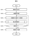
次に、図3を用いてX線CT装置の撮影処理フローを説明する。まず、入力装置121を介して撮影条件が設定される(ステップS201)。撮影条件は、X線管電圧やX線管電流、回転速度、コリメーション、撮影時間などである。入力された撮影条件に基づき、回転盤制御装置107は回転盤102の回転および、X線の放射領域を成形するためコリメータ103の位置を制御する(ステップS202)。
Next, the imaging processing flow of the X-ray CT apparatus will be described with reference to FIG. First, shooting conditions are set via the input device 121 (step S201). The imaging conditions include X-ray tube voltage, X-ray tube current, rotation speed, collimation, and imaging time. Based on the input imaging conditions, the
ステップS203にて、X線管制御装置108がX線管101に入力する電力を制御することにより、X線管101は撮影条件に応じたX線を照射する。X線検出器104は、X線管101から照射され、被検体を透過したX線を多数のX線検出素子131で検出し投影データとして出力する。
In step S203, the
ステップS205では、ステップS201で入力された撮影時間分の投影データを取得したかにより撮影終了を判定する。必要な投影データを取得完了した場合は撮影終了処理(ステップS206)へ移行する。投影データの取得が未完の場合は、回転盤制御装置107は回転盤102を所定角度回転させ、異なる角度から被検体に再度X線を照射し、被検体を透過したX線をX線検出器104で検出し、投影データとして出力する(ステップS203)。
In step S205, the end of shooting is determined depending on whether the projection data for the shooting time input in step S201 has been acquired. When the acquisition of the necessary projection data is completed, the process proceeds to the shooting end process (step S206). If the acquisition of projection data is incomplete, the
回転盤102を1回転させる間に例えば千回から数千回の投影データの取得が行われる。一連の投影データ取得の途中でX線源の焦点位置が移動するとX線の感度特性が変化し、画像劣化の原因となる。このような変化を抑制するため、撮影期間中に1または複数回、焦点移動に対する補正を実施する(ステップS204)。例えば、回転盤102の任意の回転角度ごと、例えば、360°毎に焦点移動補正を行ってもよいし、45°毎に焦点移動補正を行ってもよい。焦点移動補正の詳細については以下で詳述する。
During one rotation of the
ステップS206にて、撮影終了処理として、X線管制御装置108はX線管101に入力する電力を制御し、X線管101によるX線照射を終了する。また、回転盤制御装置107によって回転盤102の回転を停止させる。
In step S206, as an imaging end process, the X-ray
なお、図3には示していないが、撮影終了処理(ステップS206)実行後において、X線検出器104が取得した様々な角度からの投影データは画像演算装置122に送信され、CT画像として再構成される。再構成して得られたCT画像は表示装置125に表示される。
Although not shown in FIG. 3, after the imaging end processing (step S206) is executed, the projection data from various angles acquired by the
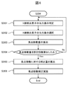
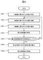
焦点移動補正の処理方法について図4を用いて説明する。焦点移動補正処理は、焦点移動補正量算出装置105による焦点移動補正量の算出と焦点移動補正装置106による算出した補正量に基づく補正を含む。焦点移動補正量の算出にあたっては、M個の投影データに基づいて算出するものとする。すなわち、角度θcにて焦点移動補正量を補正するものとすると、それ以前に取得されるθc−m(1≦m≦M)にて被検体にX線を照射して得られるM個の投影データから角度θCにおける焦点移動補正量を算出する。
The processing method of the focus movement correction will be described with reference to FIG. The focus movement correction process includes calculation of the focus movement correction amount by the focus movement correction
まず、ステップS301にて、角度θc−mにてX線検出素子131が被検体によって遮られていないかの判定(遮蔽判定)および故障していないかの判定(故障判定)をする。遮蔽判定の方法は、座標(i,j)のX線検出素子の出力値d(i,j,θc−m)と被検体が座標(i,j)のX線検出素子を遮らないときの管電流あたりの出力値dAir(i,j)との比D(i,j,θc−m)を(数1)により算出し、D(i,j,θc−m)が遮蔽判定閾値E以上であれば遮蔽なし、D(i,j,θc−m)がEより小さければ遮蔽ありとする。
First, in step S301, it is determined whether or not the
![]()
![]()
なお、dAir(i,j)は、予め被検体が座標(i,j)のX線検出素子を遮らない時に取得した角度θc−mにおける出力値でもよいし、様々な角度における出力値の平均値を用いてもよい。遮蔽判定閾値Eは、例えば0.9であり適宜適切な値を設定する。 The dAir (i, j) may be an output value at an angle θ cm acquired in advance when the subject does not block the X-ray detection element at the coordinates (i, j), or an output value at various angles. The average value of may be used. The shielding determination threshold value E is, for example, 0.9, and an appropriate value is set as appropriate.
故障判定の方法は遮蔽判定と同様に、(数1)により算出されるD(i,j,θc−m)が故障判定上限閾値Fu以上、または故障判定下限閾値Flより小さければ出力値が異常なため故障と判定する。故障判定上限閾値Fuは、例えば1.5であり適宜適切な値を設定する。同様に、故障判定下限閾値Flは、例えば0であり適宜適切な値を設定する。 The failure judgment method is the same as the shielding judgment. If D (i, j, θ cm ) calculated by (Equation 1) is equal to or more than the failure judgment upper limit threshold value Fu or smaller than the failure judgment lower limit threshold value Fl, the output value is Judged as a failure because it is abnormal. The failure determination upper limit threshold value Fu is, for example, 1.5, and an appropriate value is set as appropriate. Similarly, the failure determination lower limit threshold value Fl is, for example, 0, and an appropriate value is set as appropriate.
次に、ステップS302にて焦点移動量の算出に用いるX線検出素子131を選択する。焦点移動量の算出には、X線検出器104のうち、フロント側X線検出素子の出力値dfとリア側X線検出素子の出力値drの1つずつの対(df,dr)を選択して用いる。出力値dfと出力値drとは、角度θc−mにてX線を照射したときに被検体によって遮られていない正常なX線検出素子131の出力値の中から、次の2つの条件を満たす出力値の対(df,dr)とする。
Next, in step S302, the
条件1:X線検出器104のy軸に対して線対称位置にあるX線検出素子131の出力値の対か、X線検出器104の中心132に対して点対称位置にあるX線検出素子131の出力値の対である。
Condition 1: A pair of output values of the
条件2:X線検出器104のz軸方向に対して最も外側、かつy軸方向に対して最も内側に位置するX線検出素子131の出力値の対である。
Condition 2: A pair of output values of the
なお、条件を満たす出力値の対が複数ある場合は、y軸方向(チャネル方向)の座標jが最も小さいX線検出素子の出力値を含む対を優先して選択する。 When there are a plurality of pairs of output values satisfying the conditions, the pair including the output value of the X-ray detection element having the smallest coordinate j in the y-axis direction (channel direction) is preferentially selected.
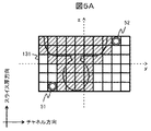
図5A,図5Bに、条件1及び条件2に基づき選択されたX線検出素子131の対の例を示す。X線管101およびX線検出器104が被検体109の正面にある場合が図5Aであり、側面にある場合が図5Bである。被検体によって遮蔽されているX線検出素子については網掛けで示している。なお、図ではX線管101からのX線が照射される範囲のX線検出器104を示している。すなわち、撮影時のスライス厚の設定によっては撮影時にそもそもX線が照射されないX線検出素子131が存在する可能性があるが、それらについては表示を省略している。
5A and 5B show an example of a pair of
投影データ毎に、遮蔽されておらず、かつ正常なX線検出素子から条件1および条件2を満たすX線検出素子の出力値の対を選択する。このように2つの条件を設けた理由は、(1)焦点移動量の検知をしやすくするため、X線ビームのプロファイル形状の裾野付近のデータを取得するため、z軸方向にはできるだけ離れたX線検出素子の対を選択する、(2)後述する取り付け誤差のように他の要因による強度変化を受けるため、y軸方向には中心(またはz軸)にできるだけ近接したX線検出素子の対を選択する、ようにしたものである。
For each projection data, a pair of output values of the X-ray detection element satisfying the
図5Aの例では、(df,dr)として(X線検出素子51の出力値,X線検出素子52の出力値)を選択する。なお、y軸に対してリア側X線検出素子52と線対称の位置にあるX線検出素子も条件1,2を満たしているが、y軸方向の座標jがより小さいフロント側X線検出素子51を選択している。また、図5Bの例では、(df,dr)として(X線検出素子53の出力値,X線検出素子54の出力値)を選択する。
In the example of FIG. 5A, (output value of the
ステップS303にて、角度θc−mにてX線を照射することによって取得された撮像データにおいて選択されたX線検出素子の出力値の対(df(θc−m),dr(θc−m))を用いて焦点移動量Z(R(θc−m))を算出する。焦点移動量Zは、(数2)に示す出力値dfと出力値drの比R(θc−m)と(数3)に示す比R(θc−m)を変数とする多項式により算出する。 In step S303, a pair of output values of the X-ray detection element selected in the imaging data acquired by irradiating X-rays at an angle θ cm (df (θ cm ), dr (θ c ). -M )) is used to calculate the focal movement amount Z (R (θ cm )). The focus movement amount Z is calculated by a polynomial with the ratio R (θ cm ) of the output value df and the output value dr shown in (Equation 2) and the ratio R (θ c−m ) shown in (Equation 3) as variables. To do.

![]()
![]()
数3における多項式の係数akは、R(θc−m)とz軸方向の焦点移動量を関連付ける変換係数である。算出したZ(R(θc−m))は記憶しておく。
The coefficient ak of the polynomial in
なお、焦点移動補正量算出装置105のZ(R(θc−m))の演算処理の負担を軽減するため、R(θ)に対応するZ(R(θ))を予め算出および記憶しておき、予め算出したZ(R(θ))を参照してR(θc−m)に対応するZ(R(θc−m))を求めてもよい。また、投影データを取得する角度ごとに連続してZ(R(θc−m))を算出するのではなく、一定角度ごと、すなわち一定時間間隔をあけてZ(R(θc−m))を算出してもよい。
In order to reduce the burden of arithmetic processing of Z (R (θ cm )) of the focus movement correction
ステップS304にて、焦点移動量Z(R(θc−m))の算出回数を判定する。焦点移動に対する補正量C(θc)には例えば、θc近傍であるθc−1にて算出したZ(R(θc−1))を用いることもできるが、複数のZ(R(θc−m))(1≦m≦M)の代表値を用いればノイズ成分を除去できるためC(θc)の精度が向上する。一方で、Z(R(θc−m))の算出回数を多くするとC(θc)の算出を開始するまでの時間が長くなる。そのため、装置ごとの焦点移動特性を考慮し適切な算出回数Mを設定しておく。Z(R(θc−m))の算出回数が設定回数Mよりも少ない場合はステップS301からS303を繰り返し、算出回数が設定回数Mを満たす場合はステップS305に進む。 In step S304, the number of times the focus movement amount Z (R (θ cm )) is calculated is determined. The correction amount C (θ c) for the focus shift example, Z calculated in theta c-1 in the vicinity θ c (R (θ c- 1)) can be used, a plurality of Z (R ( If the representative values of θ c−m )) (1 ≦ m ≦ M) are used, the noise component can be removed, so that the accuracy of C (θ c ) is improved. On the other hand, if the number of times Z (R (θ c−m )) is calculated is increased, the time until the calculation of C (θ c ) is started becomes longer. Therefore, an appropriate calculation number M is set in consideration of the focus movement characteristics of each device. If the number of calculations of Z (R (θ cm )) is less than the set number of times M, steps S301 to S303 are repeated, and if the number of calculations satisfies the set number of times M, the process proceeds to step S305.
ステップS305にて、角度θcにおける焦点移動に対する補正量C(θc)を算出する。複数のZ(R(θc−m))(1≦m≦M)の代表値の取り方はいろいろ考えられるが、ここで焦点移動量の平均値とし(数4)により算出する。 In step S305, the correction amount C (θ c ) for the focus movement at the angle θ c is calculated. There are various ways to take representative values of a plurality of Z (R (θ c−m )) (1 ≦ m ≦ M), but here, the average value of the focal movement amount is used and calculated by (Equation 4).
![]()
![]()
その後、ステップS306にて、焦点移動補正装置106が焦点移動補正量算出装置105の補正量C(θc)の算出結果に基づき、X線管101の位置を移動させることで焦点移動の影響を補正する。
After that, in step S306, the focus
本実施例では、遮蔽判定および故障判定を行った後に、X線検出素子131の出力値の中から適切な出力値を選択してX線管101の焦点移動量を算出して補正するため、被検体によりX線検出器の一部が遮蔽されている場合や特定のX線検出素子131が故障し出力値が異常となっている場合においてもX線管101の焦点移動補正を行うことが可能となる。そのため、被検体の撮影中において焦点移動に起因するアーチファクトやCT値の変動が生じにくくなり断層画像の画質が向上する。また、故障した特定のX線検出素子131が断層画像に与える悪影響が十分小さければX線CT装置1の動作を続けることも可能となる。
In this embodiment, after performing the shielding determination and the failure determination, an appropriate output value is selected from the output values of the
先に、図5A及び図5Bを用いて焦点移動補正量の算出方法について説明したが、本実施例の焦点移動補正量の算出方法はこれに限られない。フロント側X線検出素子の出力値とリア側X線検出素子の出力値との対(df,dr)として、それぞれ複数のフロント側X線検出素子の出力値dfの代表値(例えば、加算値または平均値)、複数のリア側X線検出素子の出力値drの代表値(例えば、加算値または平均値)を用いる例について説明する。 Although the method of calculating the focus movement correction amount has been described above with reference to FIGS. 5A and 5B, the calculation method of the focus movement correction amount of this embodiment is not limited to this. As a pair (df, dr) of the output value of the front side X-ray detection element and the output value of the rear side X-ray detection element, each is a representative value (for example, an addition value) of the output value df of a plurality of front side X-ray detection elements. Or an average value) and a representative value (for example, an addition value or an average value) of the output value dr of the plurality of rear side X-ray detection elements will be described.
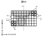
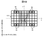
図5A及び図5Bの例では、条件を満たす1つのフロント側X線検出素子と1つのリア側X線検出素子との対を選択していた。これに対し、図6A及び図6Bの例では、条件を満たす1つのフロント側X線検出素子と1つのリア側X線検出素子との対を複数選択し、選択された対のフロント側X線検出素子の加算値または平均値、選択された対のリア側X線検出素子の加算値または平均値を出力値とする。ただし、選択する対の数が多くなるほど演算負荷が増大するため、この点を考慮して適切な数を定める。 In the examples of FIGS. 5A and 5B, a pair of one front-side X-ray detection element and one rear-side X-ray detection element satisfying the conditions was selected. On the other hand, in the examples of FIGS. 6A and 6B, a plurality of pairs of one front side X-ray detection element and one rear side X-ray detection element satisfying the conditions are selected, and the selected pair of front side X-rays. The added value or the average value of the detection elements, and the added value or the average value of the selected pair of rear X-ray detection elements are used as the output value. However, as the number of pairs to be selected increases, the calculation load increases, so an appropriate number is determined in consideration of this point.
図6A,図6Bは条件1及び条件2に基づき選択された4組のX線検出素子131の対の例である。X線管101およびX線検出器104が被検体109の正面にある場合が図6Aであり、側面にある場合が図6Bである。被検体によって遮蔽されているX線検出素子については網掛けで示している。図5A,図5Bと同様にX線管101からのX線が照射される範囲のX線検出器104のみを示している。投影データ毎に、遮蔽されておらず、かつ正常なX線検出素子から条件1および条件2を満たす複数のX線検出素子の出力値の対を選択する。
6A and 6B are examples of a pair of four sets of
図6Aの例では、出力値dfを求めるため4つのフロント側X線検出素子56(出力値dfn)を、出力値drを求めるため4つのリア側X線検出素子57(出力値drn)を選択する。同様に、図6Bの例では、出力値dfを求めるため4つのフロント側X線検出素子58(出力値dfn)を、出力値drを求めるため4つのリア側X線検出素子59(出力値drn)を選択する。 In the example of FIG. 6A, four front side X-ray detection elements 56 (output value df n ) are used to obtain the output value df, and four rear side X-ray detection elements 57 (output value dr n ) are used to obtain the output value dr. Select. Similarly, in the example of FIG. 6B, four front side X-ray detection elements 58 (output value df n ) are used to obtain the output value df, and four rear side X-ray detection elements 59 (output value) are used to obtain the output value dr. Select dr n ).
選択する対の数をNとし、角度θc−mにてX線を照射することによって取得された撮像データにおいて選択されたX線検出素子の出力値の複数の組み合わせ(dfn(θc−m),drn(θc−m))(1≦n≦N)を選択し、代表値として平均値を用いるとすると、 Let N be the number of pairs to be selected, and a plurality of combinations of output values of the X-ray detection element selected in the imaging data acquired by irradiating X-rays at an angle θ c-m (df n (θ c-). If m ), dr n (θ c−m )) (1 ≦ n ≦ N) are selected and the average value is used as the representative value,
![]()
![]()
![]()
![]()
(数5)、(数6)により(df(θc−m),dr(θc−m))を求め、これに基づき、上述の通り、焦点移動量Z(R(θc−m))、補正量C(θc)を算出する。 (5) and (6) obtains a (df (θ c-m) , dr (θ c-m)), based on this, as described above, the focus movement amount Z (R (θ c-m ) ), The correction amount C (θ c ) is calculated.
このように、角度θc−mにおいて複数のX線検出素子131の出力値の複数の組み合わせを選択して焦点移動量の算出を行うためノイズ成分を除去することが可能であり、焦点移動量の精度が向上する。また、ステップS304における焦点移動量の算出回数を低減しても一定の精度を保つことができるため、焦点移動に対する補正量の算出頻度を多くすることができる。
In this way, since a plurality of combinations of output values of the plurality of
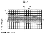
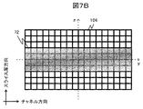
さらに、焦点移動補正量の算出方法の別の変形例について説明する。X線CT装置1では、組立時にX線管101やコリメータ103、X線検出器104の取り付け誤差が生じることがあり、このような機械的な誤差は、図7Aに示すようなX線検出器104に照射されるX線の歪みや図7Bに示すようなX線強度の不均一を生ずることがある。X線検出器104に照射されるX線71,72につき、その強度の不均一をその濃淡により表現している。濃度が高い方が、X線強度が高いことを示す。この結果、スライス厚方向i番目のチャネル方向1〜J番目におけるX線検出素子(i,1)〜(i,J)の出力値には、例えば、図8に示すような特性が生じる。
Further, another modification of the method of calculating the focus movement correction amount will be described. In the
このような特性を考慮した焦点移動補正量の算出方法を図9に示す。図4と共通のステップについては説明を省略するが、ステップS401において、選択したX線検出素子131の出力値にチャネル方向のX線に対する出力特性を考慮した係数(X線出力特性係数α(i,j))を乗じて補正を行う。X線出力特性係数α(i,j)は予め被検体によって遮られていない状態で、スライス厚方向i番目のチャネル方向1〜J番目におけるX線検出素子(i,1)〜(i,J)の出力値を用いて算出し記憶しておく。
FIG. 9 shows a method of calculating the focus movement correction amount in consideration of such characteristics. Although the description of the steps common to FIG. 4 will be omitted, in step S401, the output value of the selected
![]()
![]()
d’(i,j,θc−m)は実測の出力値であり、後続するステップS303では実測の出力値を(数7)により補正した出力値d(i,j,θc−m)を用いて焦点移動量の算出を行う。 d'(i, j, θ cm ) is the actually measured output value, and in the subsequent step S303, the output value d (i, j, θ cm ) obtained by correcting the actually measured output value by (Equation 7). Is used to calculate the amount of focus movement.
これにより、チャネル方向のX線検出素子131の出力特性を補正して焦点移動量の算出を行うため、機械的な誤差の影響を低減し高精度な焦点移動量の算出が可能となる。
As a result, the output characteristic of the
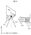
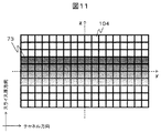
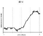
さらに、焦点移動補正量の算出方法の別の変形例について説明する。X線管101は、図10に示すように円錐台形状の回転する陽極201と電子ビーム203を放出する陰極202とを備え、陽極201の側面に陰極202が放出した電子ビーム203を当てることでX線を発生させる。発生したX線は拡散しながら広がるが、X線204の陰極側が陽極201を透過する距離d1とX線204の陽極側が陽極201を透過する距離d2とを比べるとd2の方が長くX線の強度はより減弱するため、X線検出器104に入射するX線は図11に示すようにz軸方向(スライス厚方向)にX線強度が不均一となる(ヒール効果)。X線検出器104に照射されるX線73につき、その強度の不均一をその濃淡により表現している。濃度が高い方が、X線強度が高いことを示す。ヒール効果により、チャネル方向j番目のスライス厚方向1〜I番目におけるX線検出素子(1,j)〜(I,j)の出力値において図12に示すような特性が生じる。
Further, another modification of the method of calculating the focus movement correction amount will be described. As shown in FIG. 10, the
このような特性を考慮して、焦点移動補正量の算出を図9にしたがって実行する。ステップS401において、選択したX線検出素子131の出力値にチャネル厚方向のX線に対する出力特性を考慮した係数(ヒール効果補正係数β(i,j))を乗じて補正を行う。ヒール効果補正係数β(i,j)は予め被検体によって遮られていない状態で、チャネル方向j番目のスライス厚方向1〜I番目におけるX線検出素子(1,j)〜(I,j)の出力値を用いて算出し記憶しておく。
In consideration of such characteristics, the calculation of the focus movement correction amount is performed according to FIG. In step S401, the output value of the selected
![]()
![]()
d’(i,j,θc−m)は実測の出力値であり、後続するステップS303では実測の出力値を(数8)により補正した出力値d(i,j,θc−m)を用いて焦点移動量の算出を行う。 d'(i, j, θ cm ) is the actually measured output value, and in the subsequent step S303, the actually measured output value is corrected by (Equation 8) and the output value d (i, j, θ cm ). Is used to calculate the amount of focus movement.
これにより、スライス厚方向のX線検出素子131の出力特性を補正して焦点移動量の算出を行うため、ヒール効果の影響を低減し高精度な焦点移動量の算出が可能となる。
As a result, the output characteristic of the
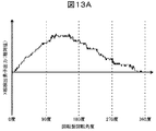
さらに、焦点移動補正量の算出方法の別の変形例について説明する。X線CT装置1では、回転盤102の回転による遠心力などの外力によってX線管101の焦点移動が生じる。この際、X線検出器104を構成するX線検出素子131の出力は図13A,図13Bに示すような周期的な出力変動特性が生ずる。例えば、フロント側X線検出素子では図13Aのように周期的に出力が大きくなり、逆にリア側X線検出素子では図13Bのように周期的に出力が小さくなる。
Further, another modification of the method of calculating the focus movement correction amount will be described. In the
このような特性を考慮して、焦点移動補正量の算出を図9にしたがって実行する。ステップS401において、選択したX線検出素子131の出力値に回転盤回転角度に対する出力特性を考慮した係数(回転盤回転角度係数γ(i,j,θc−m),δ(i,j,θc−m))を乗じて補正を行う。回転盤回転角度係数γ(i,j,θc−m),δ(i,j,θc−m)は予め被検体によって遮られていない状態で、回転盤回転角度毎のX線検出素子の出力値を用いて算出し記憶しておく。
In consideration of such characteristics, the calculation of the focus movement correction amount is performed according to FIG. In step S401, the output value of the selected
![]()
![]()
![]()
![]()
df’(i,j,θc−m)はフロント側X線検出素子の実測での出力値、dr’(i,j,θc−m)はリア側X線検出素子の実測での出力値である。後続するステップS303では実測の出力値を(数9)または(図10)により補正した出力値df(i,j,θc−m)またはdr(i,j,θc−m)を用いて焦点移動量の算出を行う。 df'(i, j, θ cm ) is the actual output value of the front X-ray detector, and dr'(i, j, θ cm ) is the actual output of the rear X-ray detector. The value. In the subsequent step S303, the actually measured output value is corrected by (Equation 9) or (FIG. 10) using the output value df (i, j, θ cm ) or dr (i, j, θ cm ). Calculate the amount of focus movement.
これにより、X線検出素子131の回転盤回転角度に対する周期的な出力変動特性を補正して焦点移動量の算出を行うため、回転盤回転角度の影響を低減し焦点移動に対する補正量の算出ステップS303と焦点移動補正ステップS306に一定の間隔がある場合でも適切な焦点移動補正が可能となる。
As a result, the focal movement amount is calculated by correcting the periodic output fluctuation characteristic with respect to the rotation disk rotation angle of the
以上、焦点移動補正の算出方法につきいくつかの変形例を説明したが、これらは単独での、あるいは組み合わせての適用が可能なものである。 As described above, some modifications of the method of calculating the focus movement correction have been described, but these can be applied individually or in combination.
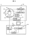
次に、実施例2のX線CT装置2について図14を用いて説明する。実施例1のX線CT装置1との異なる点は、焦点移動補正装置110がX線検出器104の位置を制御することで焦点移動の影響を補正することである。焦点移動補正のフローについては図3、図4、図9に示すとおり実施例1と同様であるが、ステップS306(図4、図9)における焦点移動補正実施の処理が異なる。すなわち、ステップS306にて、焦点移動補正装置110が焦点移動補正量算出装置105の算出結果に基づいてX線検出器104の位置を移動させることで焦点移動の影響を補正する。焦点移動補正は、回転盤102の任意の回転角度毎、例えば、360°毎に焦点移動補正を行ってもよいし、45°毎に焦点移動補正を行ってもよい。
Next, the
次に、実施例3のX線CT装置3について図15を用いて説明する。実施例1のX線CT装置1との異なる点は、焦点移動補正装置111がコリメータ103の位置を制御することで焦点移動の影響を補正することである。焦点移動補正のフローについては図3、図4、図9に示すとおり実施例1と同様であるが、ステップS306(図4、図9)における焦点移動補正実施の処理が異なる。
Next, the
ステップS306にて、焦点移動補正装置111が焦点移動補正量算出装置105の算出結果に基づいてコリメータ103の位置を移動させることで焦点移動の影響を補正する。すなわち、X線管101の焦点の移動に伴うX線の照射範囲の移動をコリメータ103の位置を制御して補正する。コリメータ103の位置制御による焦点移動補正について図16A〜Cを用いて説明する。
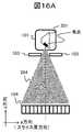
In step S306, the focus
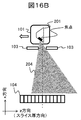
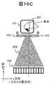
焦点移動前は、図16Aに示すようにX線管101が照射するX線204はX線検出器104の全ての列に入射している。しかしながら、焦点移動が生じることにより、図16Bに示すように、X線管101が照射するX線はX線検出器104の一部の列にしか入射しなくなり、かつX線検出器104の外側に不要なX線が照射するようになる。このような焦点移動に対してコリメータ103の位置制御による焦点移動補正を行うと、図16Cに示すようにX線管101が照射するX線は図16A同様にX線検出器104の全ての列に入射され、図16Bの様な不要なX線の照射がなくなる。焦点移動補正は、回転盤102の任意の回転角度毎、例えば、360°毎に焦点移動補正を行ってもよいし、45°毎に焦点移動補正を行ってもよい。
Before the focus shift, as shown in FIG. 16A, the
1,2,3:X線CT装置、100:スキャンガントリ部、101:X線管、102:回転盤、103:コリメータ、104:X線検出器、105:焦点移動補正量算出装置、106,110,111:焦点移動補正装置、107:回転盤制御装置、108:X線管制御装置、109:被検体、120:操作卓、121:入力装置、122:画像演算装置、123:記憶装置、124:システム制御装置、125:表示装置、131:X線検出素子。 1,2,3: X-ray CT device, 100: scan gantry section, 101: X-ray tube, 102: turntable, 103: collimator, 104: X-ray detector, 105: focus movement correction amount calculation device, 106, 110, 111: focus movement correction device, 107: turntable control device, 108: X-ray tube control device, 109: subject, 120: operation console, 121: input device, 122: image calculation device, 123: storage device, 124: System control device, 125: Display device, 131: X-ray detection element.
Claims (11)
前記X線管に対向配置され、前記X線管からのX線の強度を出力するX線検出素子を複数有するX線検出器と、
前記X線管及び前記X線検出器を搭載し、被検体の周囲を回転する回転盤と、
前記X線管の焦点移動量を算出し、算出した焦点移動量から焦点移動補正量を算出する焦点移動補正量算出装置と、
前記焦点移動補正量に基づき焦点移動補正を行う焦点移動補正装置とを有し、
前記焦点移動補正量算出装置は、前記X線検出器のX線検出素子の各々について被検体による遮蔽の有無を判定し、遮蔽されていないと判定されたX線検出素子から所定の条件を満たすX線検出素子を選択し、選択されたX線検出素子の出力値から焦点移動量を算出するX線CT装置。 X-ray tube and
An X-ray detector which is arranged to face the X-ray tube and has a plurality of X-ray detection elements that output the intensity of X-rays from the X-ray tube.
A turntable equipped with the X-ray tube and the X-ray detector and rotating around the subject,
A focus movement correction amount calculation device that calculates the focus movement amount of the X-ray tube and calculates the focus movement correction amount from the calculated focus movement amount.
It has a focus movement correction device that performs focus movement correction based on the focus movement correction amount.
The focus movement correction amount calculation device determines whether or not each of the X-ray detection elements of the X-ray detector is shielded by the subject, and satisfies a predetermined condition from the X-ray detection element determined to be unshielded. An X-ray CT apparatus that selects an X-ray detection element and calculates the amount of focus movement from the output value of the selected X-ray detection element.
前記焦点移動補正量算出装置は、前記X線検出器のX線検出素子の各々について故障の有無を判定し、遮蔽されていない、または故障していないと判定されたX線検出素子から前記所定の条件を満たすX線検出素子を選択し、選択されたX線検出素子の出力値から焦点移動量を算出するX線CT装置。 In claim 1,
The focus movement correction amount calculation device determines the presence or absence of a failure in each of the X-ray detection elements of the X-ray detector, and the predetermined X-ray detection element determined to be unshielded or not failed. An X-ray CT apparatus that selects an X-ray detection element satisfying the above conditions and calculates the amount of focus movement from the output value of the selected X-ray detection element.
前記回転盤が回転し、前記X線管からのX線が異なる角度で被検体に複数回照射されることにより、前記X線検出器から複数個の投影データが出力され、
前記焦点移動補正量算出装置は、前記複数個の投影データの各々について焦点移動量を算出し、算出された複数の焦点移動量の代表値を前記焦点移動補正量として算出するX線CT装置。 In claim 2,
When the turntable rotates and the X-rays from the X-ray tube are irradiated to the subject a plurality of times at different angles, a plurality of projection data are output from the X-ray detector.
The focus movement correction amount calculation device is an X-ray CT apparatus that calculates a focus movement amount for each of the plurality of projection data and calculates a representative value of the calculated plurality of focus movement amounts as the focus movement correction amount.
前記焦点移動補正量算出装置は、前記所定の条件として、
前記X線検出器の中心を通りチャネル方向に伸びる第1の軸に対して線対称位置にあるX線検出素子の対、または前記X線検出器の中心に対して点対称位置にあるX線検出素子の対であって、
前記X線検出器の中心を通りスライス厚方向に伸びる第2の軸の方向に対して最も外側、かつ前記第1の軸の方向に対して最も内側に位置するX線検出素子の対を含むX線CT装置。 In claim 3,
The focus movement correction amount calculation device is subject to the predetermined conditions.
A pair of X-ray detectors that are line-symmetrical with respect to the first axis that passes through the center of the X-ray detector and extends in the channel direction, or X-rays that are point-symmetrical with respect to the center of the X-ray detector. A pair of detection elements
Includes a pair of X-ray detectors located on the outermost side in the direction of the second axis extending in the slice thickness direction through the center of the X-ray detector and on the innermost side in the direction of the first axis. X-ray CT device.
前記焦点移動補正量算出装置は、前記所定の条件を満たす複数のX線検出素子の対を選択し、
前記複数のX線検出素子の対は、それぞれ前記第1の軸よりも被検体を載せる寝台側に位置するフロント側X線検出素子と、前記フロント側X線検出素子と前記第1の軸に対して線対称位置または前記X線検出器の中心に対して点対称位置にあるリア側X線検出素子との対であり、
前記複数のX線検出素子の対における複数の前記フロント側X線検出素子の出力値の代表値、及び前記複数のX線検出素子の対における複数の前記リア側X線検出素子の出力値の代表値から焦点移動量を算出するX線CT装置。
In claim 4,
The focus movement correction amount calculation device selects a pair of a plurality of X-ray detection elements satisfying the predetermined conditions, and selects a pair of X-ray detection elements.
The pair of the plurality of X-ray detection elements is formed on the front side X-ray detection element located on the bed side on which the subject is placed, the front side X-ray detection element, and the first axis, respectively, with respect to the first axis. On the other hand, it is a pair with a rear X-ray detection element located at a line-symmetrical position or a point-symmetrical position with respect to the center of the X-ray detector.
Representative value of the output values of the plurality of the front-side X-ray detection elements in the pairs of the plurality of X-ray detecting elements, and the output values of the plurality of the rear-side X-ray detection elements in the pairs of the plurality of X-ray detecting elements An X-ray CT device that calculates the amount of focus movement from a representative value.
前記焦点移動補正量算出装置は、選択されたX線検出素子の出力値に対して、前記X線検出器に照射されるX線強度のチャネル方向への不均一に起因するチャネル方向のX線検出素子の出力特性の補正を行った補正出力値を用いて焦点移動量を算出するX線CT装置。 In claim 3,
The focus movement correction amount calculating device, the output value of the X-ray detection elements selected, X-rays in the channel direction unevenly due to the channel direction of the X-ray intensity irradiated to the X-ray detector An X-ray CT apparatus that calculates the amount of focus movement using the corrected output value obtained by correcting the output characteristics of the detection element .
前記焦点移動補正量算出装置は、選択されたX線検出素子の出力値に対して、前記X線検出器に照射されるX線強度のスライス厚方向への不均一に起因するスライス厚方向のX線検出素子の出力特性の補正を行った補正出力値を用いて焦点移動量を算出するX線CT装置。 In claim 3,
The focus movement correction amount calculation device is in the slice thickness direction due to the non-uniformity of the X-ray intensity irradiated to the X-ray detector in the slice thickness direction with respect to the output value of the selected X-ray detection element. An X-ray CT apparatus that calculates the amount of focus movement using a corrected output value obtained by correcting the output characteristics of an X-ray detection element .
前記焦点移動補正量算出装置は、選択されたX線検出素子の出力値に対して、前記回転盤の回転に起因する前記回転盤の回転角度に対するX線検出素子の出力変動特性の補正を行った補正出力値を用いて焦点移動量を算出するX線CT装置。
In claim 3,
The focus movement correction amount calculation device corrects the output fluctuation characteristic of the X-ray detection element with respect to the rotation angle of the rotating disk due to the rotation of the rotating disk with respect to the output value of the selected X-ray detecting element. An X-ray CT device that calculates the amount of focus movement using the corrected output value.
前記焦点移動補正装置は前記焦点移動補正量に基づき前記X線管の位置を移動させるX線CT装置。 In any one of claims 1 to 8,
The focus movement correction device is an X-ray CT device that moves the position of the X-ray tube based on the focus movement correction amount.
前記焦点移動補正装置は前記焦点移動補正量に基づき前記X線検出器の位置を移動させるX線CT装置。 In any one of claims 1 to 8,
The focus movement correction device is an X-ray CT device that moves the position of the X-ray detector based on the focus movement correction amount.
前記X線管から発生するX線の照射領域を成形するコリメータを有し、
前記焦点移動補正装置は前記焦点移動補正量に基づき前記コリメータの位置を移動させるX線CT装置。 In any one of claims 1 to 8,
It has a collimator that forms an irradiation region of X-rays generated from the X-ray tube.
The focus movement correction device is an X-ray CT device that moves the position of the collimator based on the focus movement correction amount.
Priority Applications (1)
| Application Number | Priority Date | Filing Date | Title |
|---|---|---|---|
| JP2017008493A JP6777556B2 (en) | 2017-01-20 | 2017-01-20 | X-ray CT device |
Applications Claiming Priority (1)
| Application Number | Priority Date | Filing Date | Title |
|---|---|---|---|
| JP2017008493A JP6777556B2 (en) | 2017-01-20 | 2017-01-20 | X-ray CT device |
Publications (3)
| Publication Number | Publication Date |
|---|---|
| JP2018114211A JP2018114211A (en) | 2018-07-26 |
| JP2018114211A5 JP2018114211A5 (en) | 2019-08-15 |
| JP6777556B2 true JP6777556B2 (en) | 2020-10-28 |
Family
ID=62983571
Family Applications (1)
| Application Number | Title | Priority Date | Filing Date |
|---|---|---|---|
| JP2017008493A Active JP6777556B2 (en) | 2017-01-20 | 2017-01-20 | X-ray CT device |
Country Status (1)
| Country | Link |
|---|---|
| JP (1) | JP6777556B2 (en) |
Families Citing this family (2)
| Publication number | Priority date | Publication date | Assignee | Title |
|---|---|---|---|---|
| ES2972236T3 (en) * | 2021-11-03 | 2024-06-11 | Bruker Belgium S A | A method for obtaining a CT image of an object with bead compensation in image space |
| CN117137504B (en) * | 2023-10-30 | 2024-03-15 | 赛诺威盛科技(北京)股份有限公司 | Correction tool and correction method for detector module of medical imaging equipment |
Family Cites Families (7)
| Publication number | Priority date | Publication date | Assignee | Title |
|---|---|---|---|---|
| JP4314645B2 (en) * | 1998-07-17 | 2009-08-19 | 株式会社島津製作所 | X-ray CT system |
| JP4298011B2 (en) * | 1998-08-06 | 2009-07-15 | 株式会社東芝 | X-ray fan beam position movement detection system and CT scanner apparatus using the same |
| US6310938B1 (en) * | 1999-08-27 | 2001-10-30 | General Electric Company | Methods and apparatus for calibrating CT x-ray beam tracking loop |
| JP2003210454A (en) * | 2002-01-23 | 2003-07-29 | Hitachi Medical Corp | X-ray ct apparatus |
| JP5242350B2 (en) * | 2008-11-13 | 2013-07-24 | 株式会社日立メディコ | X-ray CT system |
| WO2011105472A1 (en) * | 2010-02-26 | 2011-09-01 | 株式会社 日立メディコ | X-ray imaging device |
| US20160199019A1 (en) * | 2015-01-13 | 2016-07-14 | Arineta Ltd. | Method and apparatus for focal spot position tracking |
-
2017
- 2017-01-20 JP JP2017008493A patent/JP6777556B2/en active Active
Also Published As
| Publication number | Publication date |
|---|---|
| JP2018114211A (en) | 2018-07-26 |
Similar Documents
| Publication | Publication Date | Title |
|---|---|---|
| JP7073380B2 (en) | Self-calibration CT detector, system and method for self-calibration | |
| US8983165B2 (en) | System and method for measuring X-ray beam profile using an area detector | |
| JP6456699B2 (en) | X-ray photon counting computed tomography apparatus, spectral correction method, and spectral correction program | |
| US9406121B2 (en) | X-ray CT apparatus and image reconstruction method | |
| US7372936B2 (en) | Radiation computed tomography apparatus and tomographic image data generating method | |
| US8290116B2 (en) | Imaging apparatus including correction unit for scattered radiation | |
| JP6603233B2 (en) | Data processing apparatus, X-ray CT apparatus, and reference correction method | |
| US7409043B2 (en) | Method and apparatus to control radiation tube focal spot size | |
| CN108697397A (en) | Radial faults imaging system and its control program | |
| EP3835830B1 (en) | Systems and methods for estimating a focal spot motion and calculating a corresponding correction | |
| JP5579505B2 (en) | X-ray CT system | |
| WO2018235393A1 (en) | X-ray CT apparatus and X-ray irradiation condition setting method | |
| JP2023157887A (en) | Photon counting CT device, photon counting CT method and program | |
| CN109893149B (en) | X-ray fluoroscopy device | |
| JP5469952B2 (en) | X-ray CT system | |
| JP5931394B2 (en) | X-ray diagnostic apparatus and dose distribution data generation method | |
| JP6777556B2 (en) | X-ray CT device | |
| JP5995491B2 (en) | X-ray CT system | |
| EP4111978B1 (en) | Systems and methods for focal spot motion detection in both x- and y-directions and correction | |
| US10070840B2 (en) | X-ray computed tomography apparatus and radiation medical imaging diagnostic apparatus | |
| US20200015769A1 (en) | X-ray computed tomography apparatus and correction method | |
| US12579719B2 (en) | Medical image processing apparatus and medical image processing method | |
| JP4761804B2 (en) | Radiation inspection apparatus and radiation inspection method | |
| JP4381099B2 (en) | Radiation tomography equipment | |
| US20230351647A1 (en) | X-ray diagnostic apparatus, medical image processing apparatus, and storage medium |
Legal Events
| Date | Code | Title | Description |
|---|---|---|---|
| A521 | Request for written amendment filed |
Free format text: JAPANESE INTERMEDIATE CODE: A523 Effective date: 20190701 |
|
| A621 | Written request for application examination |
Free format text: JAPANESE INTERMEDIATE CODE: A621 Effective date: 20190701 |
|
| A977 | Report on retrieval |
Free format text: JAPANESE INTERMEDIATE CODE: A971007 Effective date: 20200529 |
|
| A131 | Notification of reasons for refusal |
Free format text: JAPANESE INTERMEDIATE CODE: A131 Effective date: 20200623 |
|
| A521 | Request for written amendment filed |
Free format text: JAPANESE INTERMEDIATE CODE: A523 Effective date: 20200817 |
|
| TRDD | Decision of grant or rejection written | ||
| A01 | Written decision to grant a patent or to grant a registration (utility model) |
Free format text: JAPANESE INTERMEDIATE CODE: A01 Effective date: 20200915 |
|
| A61 | First payment of annual fees (during grant procedure) |
Free format text: JAPANESE INTERMEDIATE CODE: A61 Effective date: 20201008 |
|
| R150 | Certificate of patent or registration of utility model |
Ref document number: 6777556 Country of ref document: JP Free format text: JAPANESE INTERMEDIATE CODE: R150 |
|
| S111 | Request for change of ownership or part of ownership |
Free format text: JAPANESE INTERMEDIATE CODE: R313111 |
|
| R350 | Written notification of registration of transfer |
Free format text: JAPANESE INTERMEDIATE CODE: R350 |
|
| R250 | Receipt of annual fees |
Free format text: JAPANESE INTERMEDIATE CODE: R250 |
|
| R250 | Receipt of annual fees |
Free format text: JAPANESE INTERMEDIATE CODE: R250 |