JP6777534B2 - Diluting solution manufacturing equipment and diluent manufacturing method - Google Patents
Diluting solution manufacturing equipment and diluent manufacturing method Download PDFInfo
- Publication number
- JP6777534B2 JP6777534B2 JP2016254939A JP2016254939A JP6777534B2 JP 6777534 B2 JP6777534 B2 JP 6777534B2 JP 2016254939 A JP2016254939 A JP 2016254939A JP 2016254939 A JP2016254939 A JP 2016254939A JP 6777534 B2 JP6777534 B2 JP 6777534B2
- Authority
- JP
- Japan
- Prior art keywords
- liquid
- tank
- pressure
- pipe
- diluent
- Prior art date
- Legal status (The legal status is an assumption and is not a legal conclusion. Google has not performed a legal analysis and makes no representation as to the accuracy of the status listed.)
- Active
Links
Images
Landscapes
- Cleaning Or Drying Semiconductors (AREA)
- Accessories For Mixers (AREA)
Description
本発明は、希釈液製造装置および希釈液製造方法に関する。 The present invention relates to a diluent manufacturing apparatus and a diluent manufacturing method.
従来から、半導体デバイスや液晶デバイスの製造プロセスでは、半導体ウエハやガラス基板等の電子部品を洗浄する洗浄液として、不純物が高度に除去された超純水が用いられている。このような超純水を用いた洗浄では、比抵抗値の高い超純水を用いることで、洗浄時に静電気が発生しやすくなり、絶縁膜の静電破壊や微粒子の再付着を招くおそれがあることが知られている。そのため、近年では、比抵抗値(導電率)を所定の範囲に調整し、静電気の発生を抑制することを目的として、超純水にアンモニア水や炭酸水などの薬液を高精度に添加することで所定の濃度に調整された希釈液が用いられている。 Conventionally, in the manufacturing process of semiconductor devices and liquid crystal devices, ultrapure water from which impurities are highly removed has been used as a cleaning liquid for cleaning electronic parts such as semiconductor wafers and glass substrates. In such cleaning using ultrapure water, by using ultrapure water having a high specific resistance value, static electricity is likely to be generated during cleaning, which may lead to electrostatic destruction of the insulating film and reattachment of fine particles. It is known. Therefore, in recent years, chemical solutions such as ammonia water and carbonated water have been added to ultrapure water with high accuracy for the purpose of adjusting the specific resistance value (conductivity) to a predetermined range and suppressing the generation of static electricity. A diluted solution adjusted to a predetermined concentration is used.
特許文献1には、このような希釈液の製造装置として、超純水が流通する流通管と、薬液供給装置とを有し、互いに並列に接続された複数の細管を通じて薬液を流通管に供給することで、薬液を超純水で希釈した希釈液を製造する製造装置が記載されている。この製造装置では、薬液を流通管に添加する際の圧力を一定にした上で、複数の細管にそれぞれ設けられた複数の弁のうち所定数の弁を開放することで、流通管への薬液の供給量を制御することが行われている。しかしながら、薬液の供給量は、設置された細管の本数によって決定されてしまうため、細かな濃度調整を行うことができず、超純水の流量や薬液の濃度に変動がある場合、所定の濃度に調整された希釈液を製造することは困難である。
これに対し、特許文献2には、超純水を供給する第1の配管と、薬液を貯留するタンクと、タンクと第1の配管とを接続する第2の配管と、タンク内の圧力を調整する圧力調整器とを有し、圧力調整器によってタンク内の薬液を第2の配管を通じて圧送し、第1の配管内の超純水に添加して希釈液を製造する希釈液製造装置が記載されている。この製造装置によれば、超純水または希釈液の流量と希釈液の濃度との測定値に基づいてタンク内の圧力を適切に制御することで、薬液の添加量を高精度に調整することができ、その結果、所定の濃度に調整された希釈液を製造することができる。 On the other hand, in Patent Document 2, the first pipe for supplying ultrapure water, the tank for storing the chemical solution, the second pipe for connecting the tank and the first pipe, and the pressure in the tank are described. A diluent manufacturing device having a pressure regulator for adjusting, which pumps the chemical solution in the tank through the second pipe and adds it to the ultrapure water in the first pipe to produce a diluent. Are listed. According to this manufacturing equipment, the amount of chemical solution added can be adjusted with high accuracy by appropriately controlling the pressure in the tank based on the measured values of the flow rate of ultrapure water or the diluent and the concentration of the diluent. As a result, a diluted solution adjusted to a predetermined concentration can be produced.
希釈液の製造装置では、製造される希釈液が半導体ウエハやガラス基板等の電子部品の洗浄に使用される場合、所定の濃度に調整された希釈液を幅広い濃度範囲にわたって継続的かつ安定的に製造することが求められる。しかしながら、特許文献2に記載の製造装置では、実用上、タンクに加えられる圧力には上限があるため、薬液の添加量の調整範囲にも限界があり、幅広い濃度範囲に対応することは困難である。 In the diluent manufacturing apparatus, when the diluted solution to be produced is used for cleaning electronic parts such as semiconductor wafers and glass substrates, the diluted solution adjusted to a predetermined concentration is continuously and stably applied over a wide concentration range. It is required to manufacture. However, in the manufacturing apparatus described in Patent Document 2, since the pressure applied to the tank is practically limited, the adjustment range of the amount of the chemical solution added is also limited, and it is difficult to cope with a wide concentration range. is there.
そこで、本発明の目的は、所定の濃度に調整された希釈液を幅広い濃度範囲にわたって継続的かつ安定的に製造することができる希釈液製造装置を提供することである。 Therefore, an object of the present invention is to provide a diluent manufacturing apparatus capable of continuously and stably producing a diluent adjusted to a predetermined concentration over a wide concentration range.
上述した目的を達成するために、本発明の希釈液製造装置は、第1の液体に対して第2の液体を添加することで第2の液体の希釈液を製造し、ユースポイントに希釈液を供給する希釈液製造装置であって、第1の液体を供給する第1の配管と、第2の液体を貯留するタンクと、タンクと第1の配管とを接続し、互いに並列に接続された複数の第2の配管と、タンク内の圧力を調整する圧力調整部であって、タンク内の第2の液体を複数の第2の配管の少なくとも1つを通じて圧送して第1の配管に供給する圧力調整部と、第1の配管内を流れる第1の液体または希釈液の流量と希釈液の濃度との測定値に基づいて、希釈液の濃度が所定の濃度になるように、圧力調整部による第1の液体への第2の液体の添加量を調整する制御部と、を有し、複数の第2の配管は、内径および長さの少なくとも一方が互いに異なる。 In order to achieve the above-mentioned object, the diluent producing apparatus of the present invention produces a diluent of the second liquid by adding the second liquid to the first liquid, and the diluent is used as a point of use. The first pipe for supplying the first liquid, the tank for storing the second liquid, and the tank and the first pipe are connected and connected in parallel with each other. A plurality of second pipes and a pressure adjusting unit for adjusting the pressure in the tank, in which the second liquid in the tank is pumped through at least one of the plurality of second pipes to the first pipe. Based on the measured values of the flow rate of the first liquid or the diluent flowing through the first pipe and the concentration of the diluent, the pressure is adjusted so that the concentration of the diluent becomes a predetermined concentration. A control unit for adjusting the amount of the second liquid added to the first liquid by the adjusting unit is provided, and at least one of the inner diameter and the length of the plurality of second pipes is different from each other.
また、本発明の希釈液製造方法は、第1の液体に対して第2の液体を添加することで第2の液体の希釈液を製造し、ユースポイントに希釈液を供給する希釈液製造方法であって、第1の配管に第1の液体を供給する工程と、第第2の液体を貯留する第1のタンク内の圧力を調整して、第1のタンクと第1の配管とを接続し互いに並列に接続された複数の第2の配管の少なくとも1つを通じて、第1のタンク内の第2の液体を圧送して第1の配管に供給する工程であって、第1の配管内を流れる第1の液体または希釈液の流量と希釈液の濃度とを測定し、その測定値に基づいて、希釈液の濃度が所定の濃度になるように第1の液体への第2の液体の添加量を調整することを含む、第2の液体を第1の配管に供給する工程と、を含み、第2の液体を第1の配管に供給する工程が、内径および長さの少なくとも一方が互いに異なる複数の第2の配管の少なくとも1つを通じて第2の液体を圧送することを含んでいる。 Further, the method for producing a diluted solution of the present invention is a method for producing a diluted solution in which a diluted solution of a second liquid is produced by adding a second liquid to a first liquid, and the diluted solution is supplied to a use point. Therefore, the step of supplying the first liquid to the first pipe and the pressure in the first tank for storing the second liquid are adjusted to connect the first tank and the first pipe. A step of pumping a second liquid in a first tank and supplying it to a first pipe through at least one of a plurality of second pipes connected and connected in parallel with each other. The flow rate of the first liquid or the diluent flowing through the inside and the concentration of the diluent are measured, and based on the measured values, a second liquid to the first liquid is prepared so that the concentration of the diluent becomes a predetermined concentration. The step of supplying the second liquid to the first pipe, including adjusting the amount of the liquid added, and the step of supplying the second liquid to the first pipe include at least the inner diameter and the length. It involves pumping a second liquid through at least one of a plurality of second pipes, one of which is different from each other.
このような希釈液製造装置および希釈液製造方法では、内径が互いに異なる複数の第2の配管を用いることで、例えばタンク内の圧力が同じであっても互いに異なる流量で第2の液体を通過させることが可能になる。これにより、装置全体として、第2の液体の添加量の調整範囲を広げることが可能になり、幅広い濃度範囲の希釈液を製造することが可能になる。 In such a diluent manufacturing apparatus and a diluent manufacturing method, by using a plurality of second pipes having different inner diameters, for example, even if the pressure in the tank is the same, the second liquid is passed through at different flow rates. It becomes possible to make it. As a result, the adjustment range of the addition amount of the second liquid can be expanded as a whole, and the diluted solution having a wide concentration range can be produced.
以上、本発明によれば、所定の濃度に調整された希釈液を幅広い濃度範囲にわたって継続的かつ安定的に製造することができる。 As described above, according to the present invention, a diluted solution adjusted to a predetermined concentration can be continuously and stably produced over a wide concentration range.
以下、図面を参照して、本発明の実施の形態について説明する。 Hereinafter, embodiments of the present invention will be described with reference to the drawings.
(第1の実施形態)
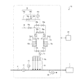
図1は、本発明の第1の実施形態に係る希釈液製造装置の概略構成図である。なお、図示した構成は、あくまで一例であって、例えば、バルブやフィルタを追加するなど、装置の使用目的や用途、要求性能に応じて適宜変更可能であることは言うまでもない。
(First Embodiment)
FIG. 1 is a schematic configuration diagram of a diluent manufacturing apparatus according to the first embodiment of the present invention. It is needless to say that the illustrated configuration is merely an example and can be appropriately changed according to the purpose of use, application, and required performance of the device, such as adding a valve or a filter.
希釈液製造装置10は、第1の液体を供給する第1の配管11と、第2の液体を貯留する2つのタンク12a,12bと、2つのタンク12a,12bと第1の配管11とを接続し、互いに並列に接続された複数の第2の配管13とを有している。第2の液体は、希釈される薬液であり、第1の液体は、第2の液体を希釈する希釈媒体である。したがって、希釈液製造装置10は、第1の配管11を流れる第1の液体に対して第2の配管13を通じて第2の液体を添加することで第2の液体の希釈液を製造し、製造された希釈液を第1の配管11を通じてユースポイント1に供給するものである。
The
第1の液体としては、その種類に特に制限はなく、超純水や純水、電解質やガスを溶解させた水、イソプロピルアルコールなどのアルコール類を利用用途に合わせて使用することができる。また、第2の液体としては、希釈されて使用される限り、その種類に特に制限はなく、炭酸水や水素水等の電解質やガスを溶解させた水やイソプロプルアルコール等のアルコール類を利用用途に合わせて使用することができる。製造される希釈液が半導体ウエハの洗浄に使用される場合、第1の液体として超純水を用い、第2の液体としてアンモニア水溶液を用いることが好ましい。あるいは、第2の液体として、水酸化テトラメチルアンモニウム(TMAH)水溶液も好適に用いることができる。なお、ここでいう超純水とは、超純水製造装置を用いて被処理水(原水)からイオンおよび非イオン性物質を除去して得られる処理水を意味し、比抵抗値が18MΩ・cm以上の処理水を意味する。 The type of the first liquid is not particularly limited, and alcohols such as ultrapure water, pure water, water in which an electrolyte or a gas is dissolved, and isopropyl alcohol can be used according to the intended use. The type of second liquid is not particularly limited as long as it is diluted and used, and electrolytes such as carbonated water and hydrogen water, water in which gas is dissolved, and alcohols such as isopropul alcohol are used. It can be used according to the application. When the produced diluent is used for cleaning semiconductor wafers, it is preferable to use ultrapure water as the first liquid and an aqueous ammonia solution as the second liquid. Alternatively, an aqueous solution of tetramethylammonium hydroxide (TMAH) can also be preferably used as the second liquid. The ultrapure water referred to here means treated water obtained by removing ions and nonionic substances from the water to be treated (raw water) using an ultrapure water production apparatus, and has a specific resistance value of 18 MΩ. It means treated water of cm or more.
2つのタンク12a,12bは、互いに並列に接続されている。すなわち、2つのタンク12a,12bは、その出口側において、それぞれバルブ14a,14bを介して複数の第2の配管13に直列に接続されている。複数の第2の配管13の入口側には、それぞれバルブ13aが設けられている。2つのタンク12a,12bのバルブ14a,14bと、複数の第2の配管13のバルブ13aとの間には、フィルタF1が設けられている。なお、2つのタンク12a,12bの出口側には、2つのバルブ14a,14bの代わりに、三方バルブが設けられていてもよい。また、2つのタンク12a,12bには、それぞれバルブ15a,15bを介して、各タンク12a,12bに第2の液体を供給する薬液供給ライン(液体供給手段)16が接続されている。バルブ15a,15bと2つのタンク12a,12bとの間には、それぞれフィルタF2,F3が設けられ、薬液供給ライン16には、バルブ16aが設けられている。さらに、2つのタンク12a,12bには、それぞれ大気開放バルブ17a,17bが設けられている。なお、2つのタンク12a,12bの入口側には、2つのバルブ15a,15bの代わりに、三方バルブが設けられていてもよい。
The two
さらに、希釈液製造装置10は、タンク12a,12b内の第2の液体を第2の配管13を通じて圧送して第1の配管11に供給するための手段として、タンク12a,12b内の圧力を調整する圧力調整部18を有している。圧力調整部18は、タンク12a,12b内にタンク加圧用ガスを供給するタンク加圧用ガス供給ライン18aと、タンク加圧用ガス供給ライン18aに設けられた給排気機構18bとから構成されている。給排気機構18bは、給気バルブ18cと排気バルブ18dとから構成され、これらを開閉することで、タンク12a,12b内を加圧したり減圧したりすることができる。なお、給排気機構18bは、図示した構成、すなわち、給気加圧機構(給気バルブ18c)と排気減圧機構(排気バルブ18d)とが別々に構成されたものに限定されるものではなく、例えば、電空レギュレータなどの給気加圧機構と排気減圧機構とが一体に構成されたものであってもよい。タンク加圧用ガス供給ライン18aは、バルブ19aを介して一方のタンク(第1のタンク)12aに接続され、バルブ19bを介して他方のタンク(第2のタンク)12bに接続されている。また、ガス供給ライン18aには、タンク加圧用ガスの供給圧力を測定する圧力計19cが設けられている。タンク加圧用ガスとしては、その種類に特に制限はないが、比較的容易に利用可能な、不活性ガスである窒素ガスを用いることが好ましい。ただし、製造される希釈液が、酸化されやすい材料を含む被処理体の洗浄やリンスに使用される場合、タンク加圧用ガスとして、酸素や空気を用いることは避けるべきであり、たとえ窒素などの不活性ガスを用いる場合であっても、不純物として含まれる酸素の影響を受ける可能性があるため、その純度にも十分に配慮することが必要である。
Further, the
本実施形態では、希釈液が製造される通常運転時、第2の液体は、2つのタンク12a,12bから交互に第1の配管11に供給される。すなわち、第1のタンク12aから第1の配管11に第2の液体が供給される第1の供給モードと、第2のタンク12bから第1の配管11に第2の液体が供給される第2の供給モードとが、各タンク12a,12b内の液位に基づいて適宜切り替えられる。例えば、第1の供給モードにおいて、第1のタンク12a内の液位が所定の下限液位を下回ると、第1のタンク12aからの第2の液体の供給が停止され、第2のタンク12bから第2の液体が供給されるようになる。この切り替え動作については後述する。
In the present embodiment, during the normal operation in which the diluent is produced, the second liquid is alternately supplied to the
また、本実施形態では、第1の配管11への第2の液体の供給は、複数の第2の配管13のうち1つを通じて行われるが、複数の第2の配管13は、第2の液体の幅広い供給量を実現するために、内径および長さの少なくとも一方が互いに異なるように構成されている。すなわち、複数の第2の配管13は、例えばタンク12a,12b内の圧力が同じであっても互いに異なる流量で第2の液体を通過させるように、内径および長さの少なくとも一方が互いに異なるように構成されている。この第2の配管13の構成についても後述する。
Further, in the present embodiment, the supply of the second liquid to the
さらに、希釈液製造装置10は、希釈液製造装置10の各種運転動作を制御する制御部20を有している。特に、制御部20は、少なくとも、第1の配管11内を流れる第1の液体の流量を測定する流量測定手段21と、希釈液の濃度を測定する濃度測定手段22との測定結果に基づいて、希釈液の濃度が所定の濃度になるように、圧力調整部18による第1の液体への第2の液体の添加量を調整することができる。以下では、制御部20による第2の液体の添加量の調整方法について説明するが、その前に、この添加量調整の基となるハーゲン・ポアズイユの法則について簡単に説明する。
Further, the
ハーゲン・ポアズイユの法則とは、円形管路内の層流の損失水頭に関する法則であり、管の内径をD[m]、管の長さをL[m]、管の両端の圧力勾配をΔP[Pa]、液体の粘性係数をμ[Pa・s]、管内を流れる液体の流量をQ[m3/s]とすると、
Q=(π×D4×ΔP)/(128×μ×L)
という関係で表される。すなわち、ハーゲン・ポアズイユの法則は、円管を流れる液体の流量Qが、円管の内径Dの4乗と両端の圧力勾配ΔPとに比例し、円管の長さLと液体の粘性係数μとに反比例する、という法則である。
Hagen-Poiseuille's law is a law concerning the head loss of laminar flow in a circular pipeline. The inner diameter of the pipe is D [m], the length of the pipe is L [m], and the pressure gradient at both ends of the pipe is ΔP. Assuming that [Pa], the viscosity coefficient of the liquid is μ [Pa · s], and the flow rate of the liquid flowing in the pipe is Q [m 3 / s],
Q = (π × D 4 × ΔP) / (128 × μ × L)
It is expressed by the relationship. That is, Hagen-Poiseuille's law states that the flow rate Q of the liquid flowing through the circular tube is proportional to the fourth power of the inner diameter D of the circular tube and the pressure gradient ΔP at both ends, and the length L of the circular tube and the viscosity coefficient μ of the liquid. It is a law that is inversely proportional to.
本実施形態の希釈液製造装置では、第2の配管を通じた第2の液体の供給に、ハーゲン・ポアズイユの法則が応用されている。第2の配管のそれぞれの長さLおよび内径Dは固定された値であり、第2の液体の種類が決定されれば、その粘性係数μも固定された値である。そのため、それぞれの第2の配管の両端間の圧力勾配ΔPに対応するタンク内の圧力を制御するだけで、それぞれの第2の配管内の流量Qを比例制御することが可能になる。 In the diluent manufacturing apparatus of the present embodiment, Hagen-Poiseuille's law is applied to the supply of the second liquid through the second pipe. The length L and the inner diameter D of each of the second pipes are fixed values, and once the type of the second liquid is determined, the viscosity coefficient μ is also a fixed value. Therefore, it is possible to proportionally control the flow rate Q in each of the second pipes only by controlling the pressure in the tank corresponding to the pressure gradient ΔP between both ends of each of the second pipes.
次に、第1のタンク12aから第1の液体に第2の液体が添加される場合の、制御部20による第2の液体の添加量の調整方法について説明する。
Next, a method of adjusting the amount of the second liquid added by the
まず、製造される希釈液の濃度の目標値が設定され、設定された目標濃度に対して、第2の液体の添加量が計算される。具体的には、流量測定手段21によって第1の液体の流量が測定され、目標濃度を達成するための第2の液体の目標添加量が計算される。次に、計算された目標添加量に対して、複数の第2の配管13のうち、使用する1つの第2の配管13が決定され、決定された第2の配管13に対して、目標添加量(流量)を実現するための第1のタンク12a内の圧力の目標値が算出される。そして、使用する第2の配管13のバルブ13aを開放した後、圧力調整部18により、算出された目標圧力に第1のタンク12a内の圧力を調整することで、第1のタンク12aから第2の配管13を通じて第1の配管11内の第1の液体に第2の液体が所定の添加量で添加される。
First, a target value for the concentration of the diluted solution to be produced is set, and the amount of the second liquid added is calculated with respect to the set target concentration. Specifically, the flow rate measuring means 21 measures the flow rate of the first liquid, and calculates the target addition amount of the second liquid to achieve the target concentration. Next, one
このとき、上述したハーゲン・ポアズイユの法則により、第2の配管13を流れる第2の液体の流量Qは第2の配管13の両端の圧力勾配ΔPに比例するという関係が成り立つ。そのため、例えば第1の液体の流量が変化した場合には、その変化に対して圧力勾配ΔPがある比例定数で比例するように、第1のタンク12a内の圧力を変化させる。例えば、第1の液体の流量が2倍になった場合、圧力勾配ΔPを2倍にして第2の液体の流量も2倍にし、第1の液体の流量が1/2になった場合、圧力勾配ΔPを1/2にして第2の液体の流量も1/2にする。このような調整方法により、結果的に第1の液体の流量と第2の液体の流量との比例関係が保たれ、第1の液体の流量が変動した場合にも、安定した濃度の希釈液を得ることができる。
At this time, according to the Hagen-Poiseuille law described above, the relationship is established that the flow rate Q of the second liquid flowing through the
ただし、第1のタンク12aにおける第2の液体の揮散や分解などにより、第2の液体自体の濃度が一定でない場合もある。その場合、製造される希釈液の濃度が、当初は目標濃度を含む所定の濃度範囲内に調整されていたとしても、その濃度範囲から徐々に外れていく可能性がある。そのため、本実施形態では、濃度測定手段22によって希釈液の濃度が測定され、測定された希釈液の濃度が所定の濃度範囲から外れていると、当該希釈液の濃度が所定の濃度範囲内に収まるように、上述の比例定数が修正される。このフィードバック制御により、装置の運転当初や希釈液の濃度の目標値が変更されたときにも、比例定数を最適な値に自動的に変更することができる。その結果、所定の濃度に調整された希釈液を安定して製造することができる。
However, the concentration of the second liquid itself may not be constant due to volatilization or decomposition of the second liquid in the
流量測定手段21としては、その構成に特に制限はなく、例えば、カルマン渦流量計や超音波流量計を用いることができる。また、流量測定手段21は、第1の配管11内を流れる第1の液体の流量変動を監視できる位置に設置されていればよく、その設置位置に特に制限はない。また、図示した実施形態では、流量測定手段21は、第1の配管11の、第2の配管13との接続部よりも上流側に設けられているが、この接続部よりも下流側に設置されて、第1の配管11内を流れる希釈液の流量を測定するようになっていてもよい。これは、第2の液体の供給量(流量)が第1の液体の流量に比べてはるかに少なく、希釈液の流量を第1の液体の流量と等価に扱うことができるためである。
The configuration of the flow rate measuring means 21 is not particularly limited, and for example, a Karman vortex flow meter or an ultrasonic flow meter can be used. Further, the flow rate measuring means 21 may be installed at a position where the flow rate fluctuation of the first liquid flowing in the
濃度測定手段22としては、希釈液の濃度を電気化学的定数として測定できるものであれば、その構成に特に制限はなく、例えば、電気導電率計、pH計、比抵抗計、ORP計(酸化還元電位計)、またはイオン電極計などを用いることができる。製造される希釈液が帯電防止や除電を目的として被処理体の洗浄やリンスに使用される場合、濃度測定手段22としては、電気導電率計や比抵抗計を用いることが好ましい。濃度測定手段22は、図示したように、第1の配管11の、第2の配管13との接続部よりも下流側に設置されているが、この設置位置において、第1の配管11に直接取り付けられていてもよく、あるいは、第1の配管11に並列に設けられたバイパス配管に取り付けられていてもよい。
The concentration measuring means 22 is not particularly limited in its configuration as long as the concentration of the diluent can be measured as an electrochemical constant. For example, an electric conductivity meter, a pH meter, a specific resistance meter, and an ORP meter (oxidation). A reduction potential meter), an ion electrodeometer, or the like can be used. When the produced diluent is used for cleaning or rinsing the object to be treated for the purpose of antistatic or static elimination, it is preferable to use an electric conductivity meter or a resistivity meter as the concentration measuring means 22. As shown in the figure, the concentration measuring means 22 is installed on the downstream side of the connection portion of the
ハーゲン・ポアズイユの法則からも理解できるように、第2の液体の供給量(流量Q)の精度は、第2の配管13の両端の圧力勾配ΔPに大きな影響を受ける。そのため、第1の配管11と第2の配管13との接続部における圧力が大きく変動する場合、所定の濃度に調整された希釈液を安定して製造することが困難になる。そのため、この接続部における圧力変動を監視するために、図示したように、第1の配管11内の圧力を測定する圧力測定手段23が設けられている。したがって、制御部20は、流量測定手段21、濃度測定手段22、および圧力測定手段23の測定結果に基づいて、希釈液の濃度を目標濃度にするための第1のタンク12a内の圧力の目標値を算出し、第2の液体の添加量の調整を行うようになっている。圧力測定手段23の構成には特に制限はなく、その設置位置も、図示した実施形態では、第2の配管13との接続部よりも上流側であるが、接続部における管内の圧力を測定することができれば、接続部よりも下流側であってもよい。
As can be understood from Hagen-Poiseuille's law, the accuracy of the supply amount (flow rate Q) of the second liquid is greatly affected by the pressure gradient ΔP at both ends of the
これまで繰り返し述べているように、第2の配管13内を流れる第2の液体の流量Qは、第2の配管13の両端の圧力勾配ΔPに比例する。そのため、この圧力勾配ΔPを大きく変化させることができれば、第2の液体の幅広い供給量(流量)を実現して、幅広い濃度範囲に対応することが可能である。しかしながら、実用上、各タンク12a,12bに加えられる圧力には上限があるため、圧力勾配ΔPを大きく変化させることは困難であり、第2の液体の添加量の調整範囲にも限界がある。
As described repeatedly so far, the flow rate Q of the second liquid flowing in the
その一方で、ハーゲン・ポアズイユの法則によれば、第2の液体の流量Qは、第2の配管13の内径D(の4乗)にも比例し、その長さLには反比例する。この点に着目し、本実施形態では、第2の液体の幅広い供給量(流量)を実現するために、複数の第2の配管13は、内径および長さの少なくとも一方が互いに異なるように構成されている。すなわち、複数の第2の配管13は、内径および長さの少なくとも一方が互いに異なることで、例えばタンク12a,12b内の圧力が同じであっても互いに異なる流量で第2の液体を通過させるように構成されている。これにより、装置全体として、第2の液体の添加量の調整範囲を広げることが可能になり、幅広い濃度範囲の希釈液を製造することが可能になる。
On the other hand, according to Hagen-Poiseuille's law, the flow rate Q of the second liquid is proportional to the inner diameter D (squared) of the
個々の第2の配管13の内径は、特定の寸法に限定されるものではないが、製造される希釈液の濃度をより精密に制御するためには、それぞれの第2の配管13の内径が0.1mmを超え4mm以下であることが好ましく、0.2mmを超え0.5mm以下であることがより好ましい。これは、第2の配管13内の第2の液体の流れが層流(規則正しい整然とした流れ)になりやすくなるためである。すなわち、管内の流れが乱流(不規則な流れ)になると、上述したハーゲン・ポアズイユの法則が成り立たなくなり、第2の配管内を流れる第2の液体の流量Qを、第2の配管の両端間の圧力勾配ΔPで比例制御することが困難になるためである。換言すると、流量Qと圧力勾配ΔPの良好な比例関係を維持するために、個々の第2の配管13は、管内を流れる第2の液体の流れが層流になっていることが好ましい。なお、この内径の好適な範囲の詳細については、特許文献1を参照されたい。
The inner diameter of each
また、個々の第2の配管13の長さについても、特定の寸法に限定されるものではないが、長さが短すぎると、管内の流量に影響が出やすく、液体の流量を配管両端の圧力勾配で比例制御することが困難になる。また、長さが長すぎると、配管の設置が困難になることに加え、配管と液体との接触面積が大きくなり、配管内の液体の汚染が増加する可能性がある。そのため、個々の第2の配管13の長さは、0.01m以上100m以下の範囲であることが好ましく、0.1m以上10m以下の範囲であることがより好ましい。
Further, the length of each
さらに、第2の配管13として内径が0.1mm以下のものや長さが100mを超えるものは、その組み合わせにもよるが、第2の液体が配管13を流れる際の抵抗が大きくなりやすく、すなわち、タンク内の圧力が高圧になりやすい。したがって、このような内径および長さは、装置を構成する部品類(配管やバルブなど)の選定が耐圧の点から困難となるため好ましくない。また、第2の配管13として内径が4mmを超えるものや長さが0.01m未満のものは、その組み合わせにもよるが、第2の液体が配管13を流れる際の抵抗が小さくなりやすく、すなわち、タンク内の圧力のわずかな変化で第2の液体の流量が変化しやすくなる。したがって、このような内径および長さは、タンク内の圧力制御が困難となるため好ましくない。
Further, the
第2の配管13の材質や形状には特に制限はないが、樹脂製の柔軟なチューブが好適に用いられる。そのような樹脂としては、PFAやETFEなどのフッ素樹脂、ポリエチレン系樹脂、ポリプロピレン系樹脂などが挙げられ、製造される希釈液が半導体ウエハの洗浄やリンスに使用される場合には、溶出の少ないフッ素樹脂が特に好ましい。また、第2の液体が揮発性のある液体の場合、管内の液体が揮発して外部に拡散することによる液体の濃度変動を抑制するために、第2の配管13としては、ガス透過性が低いものを用いることが好ましい。このことは、上述したように、製造される希釈液の用途によっては希釈液に含まれる酸素が悪影響を及ぼすこともあることから、空気中の酸素が第2の配管13の外側から内側へと拡散することを抑制し、第2の液体中の溶存酸素濃度が上昇することを抑制できる点でも好ましい。
The material and shape of the
第2の配管13の第1の配管11への接続方法としては、第1の液体と第2の液体が適切に混合するものであれば特に制限はない。例えば、第2の配管13は、その先端が第1の配管11の中心部に位置するように第1の配管11に接続されていることが好ましく、これにより、効率的に第1の液体と第2の液体を混合することができる。また、複数の第2の配管13は、構造が簡単になり、液溜まりの少ない構造にもなる点で、それぞれ個別に第1の配管11に接続されていることが好ましい。
The method of connecting the
図示した例では、4本の第2の配管13が設けられているが、第2の配管13の数は4つに限定されるものではなく、要求される希釈液の濃度範囲に応じて、例えば、2つ、3つ、または5つ以上と適宜変更可能である。それに応じて、内径と長さの組み合わせも、特定の組み合わせに限定されるものではなく、適宜変更可能である。内径と長さの組み合わせとしては、どちらか一方のみが異なるものも考えられるが、その場合、上述したように、各タンク12a,12bに加えられる圧力には上限があることから、第2の液体の添加量の調整範囲をより広げることができる点で、内径が互いに異なるものを組み合わせた方が好ましい。これは、上述したハーゲン・ポアズイユの法則により、第2の配管13を流れる第2の液体の流量Qに対し、長さLが1乗で影響するのに対して、内径Dが4乗で影響することからも明らかである。なお、本実施形態では、第1の配管11への第2の液体の供給は、複数の第2の配管13のうち1つを通じて行われるが、要求される希釈液の濃度範囲によっては、複数の第2の配管13のうち2本以上の第2の配管13を通じて行われるようになっていてもよい。
In the illustrated example, four
上述したように、本実施形態では、希釈液が製造される通常運転時、第1のタンク12aから第1の配管11に第2の液体が供給される第1の供給モードと、第2のタンク12bから第1の配管11に第2の液体が供給される第2の供給モードとの切り替えが行われる。これにより、タンクの交換作業が不要になり、装置の運転を停止する必要がなくなることで、希釈液の製造を継続的に安定して行うことが可能になる。以下、この切り替え動作について、第1の供給モードから第2の供給モードに切り替えられる場合を例に挙げて説明する。
As described above, in the present embodiment, the first supply mode in which the second liquid is supplied from the
第1の供給モードでは、タンク加圧用ガス供給ライン18aと第1のタンク12aとを接続するバルブ19aが開放されることで、第1のタンク12aにタンク加圧用ガス供給ライン18aを通じてタンク加圧用ガス(例えば、窒素ガス)が導入される。そして、圧力計19cによる測定値(第1のタンク12a内の圧力)が給排気機構18bによって目標圧力になるように調整される。こうして、第1のタンク12a内の第2の液体が、指定された第2の配管13を通じて所定の添加量で第1の配管11内の第1の液体に添加される。なお、このとき、タンク加圧用ガス供給ライン18aと第2のタンク12bとを接続するバルブ19b、薬液供給ライン16のバルブ16a、薬液供給ライン16と第1のタンク12aとの間のバルブ15a、薬液供給ライン16と第2のタンク12bとの間のバルブ15b、第1のタンク12aの大気開放バルブ17a、および第2のタンク12bの大気開放バルブ17bは、いずれも閉鎖された状態にある。また、第2のタンク12bは、わずかな量の第2の液体が貯留された待機状態にある。
In the first supply mode, the
第1のタンク12aから第1の配管11に第2の液体が供給されることで、第1のタンク12a内の液位が所定の下限液位を下回ると、薬液供給ライン16のバルブ16aが開放され、第2のタンク12bの大気開放バルブ17bが開放される。続いて、薬液供給ライン16と第2のタンク12bとの間のバルブ15bが開放され、薬液供給ライン16を通じて第2の液体が第2のタンク12bに供給されて貯留される。そして、第2のタンク12b内の液位が所定の上限液位に達すると、薬液供給ライン16のバルブ16a、第2のタンク12bの大気開放バルブ17b、および薬液供給ライン16と第2のタンク12bとの間のバルブ15bが閉鎖される。その後、タンク加圧用ガス供給ライン18aと第2のタンク12bとを接続するバルブ19bが開放され、第2のタンク12bにタンク加圧用ガス供給ライン18aを通じてタンク加圧用ガスが導入される。このとき、圧力計19cによる測定値が給排気機構18bによって目標圧力になるように調整される。すなわち、第1のタンク12a内の圧力が目標圧力に調整された状態を維持しながら、第2のタンク12b内の圧力もその目標圧力になるように調整される。第2のタンク12b内の圧力がその目標圧力に達すると、第2のタンク12bと第2の配管13とを接続するバルブ14bが開放され、続いて、第1のタンク12aと第2の配管13とを接続するバルブ14aが閉鎖される。こうして、第1のタンク12aから第2の液体が供給される第1の供給モードから、第2のタンク12bから第2の液体の供給が供給される第2の供給モードへと、供給モードの切り替えが完了する。その後、タンク加圧用ガス供給ライン18aと第1のタンク12aとを接続するバルブ19aが閉鎖され、第1のタンク12aは、次回の第1の供給モードのために第2の液体が補充されるまで待機状態になる。
When the second liquid is supplied from the
この切り替え動作では、上述したように、第2のタンク12bからの第2の液体の供給は、第2のタンク12b内の圧力が第1のタンク12a内の圧力に一致するように調整された後で行われる。これにより、第1の供給モードから第2の供給モードへの切り替え直後であっても、第1のタンク12a内の第2の液体を所定の添加量で第1の配管11内の第1の液体に添加することができる。その結果、モード切り替え時に、第2の液体の添加量の変動を極力抑えることができ、したがって、製造される希釈液の濃度変動を極力抑えることができる。
In this switching operation, as described above, the supply of the second liquid from the
上述した例では、第2のタンク12bが待機状態にあるとき、大気開放バルブ17bは閉鎖されているが、これは、第2のタンク12bへの酸素の入り込みを抑え、その後の第2のタンク12bへの第2の液体の補充時に第2の液体への酸素の溶け込みを抑えるためである。ただし、第2のタンク12bでの第2の液体への酸素の溶け込みが問題にならない場合には、大気開放バルブ17bは閉鎖された状態になくてもよい。また、第2のタンク12bへの第2の液体の補充時にタンク内の気体成分がなくなる程度まで補充を行う場合には、タンク内の大気を大気開放バルブ17bから排出することで、第2の液体への酸素の溶け込みを軽減することができるため、大気開放バルブ17bは開閉および閉鎖のいずれの状態にあってもよい。
In the above example, when the
また、上述した例では、第2のタンク12bへの第2の液体の補充は、第1の供給モードの終了間際に行われるが、補充のタイミングは、これに限定されるものではない。例えば、第1の供給モードへの切り替え直後など、第1の供給モードにおける任意のタイミングで第2の液体の補充を行うことができる。このとき、第2の液体が揮発性のある液体の場合、第2の液体の揮発を抑制するために、第2の液体の補充後に大気開放バルブ17bは閉鎖されたままであることが好ましい。
Further, in the above-described example, the replenishment of the second liquid to the
なお、第1の供給モードにおいて、第1のタンク12aが空になるまで第2の液体の供給を行うと、第2の配管にタンク加圧用ガスが溜まってしまい、次回の第1の供給モードへの切り替え時に、そのガスが第1の配管に供給され、製造される希釈液に濃度変動が発生する可能性がある。そのため、第1の供給モードから第2の供給モードへの切り替えは、上述したように、第1のタンク12aが空になる前に開始されることが好ましい。
In the first supply mode, if the second liquid is supplied until the
ところで、本実施形態の希釈液製造装置10は、ユースポイント1で希釈液の需要がないときなど、通常運転の合間に、第1の配管11への第1の液体の供給が一時的に停止されて希釈液の製造が一時的に停止される待機モードに移行することがある。このとき、例えば第1の供給モードから待機モードに移行する場合、目標圧力に調整されていた第1のタンク12a内の圧力は、安全面を考慮すると、大気圧に戻しておくことが好ましいと考えられるが、実際には、以下の点で好ましくない。
By the way, in the
すなわち、第1のタンク12a内の圧力を減圧して大気圧に戻してしまうと、高圧下で第2の液体に溶解していたガス成分が気泡として生成され、この気泡が第2の配管13内に滞留することになる。このため、通常運転再開後、第1のタンク12aを再度加圧しても第2の液体は添加されず、さらに、第1のタンク12aは過剰に加圧された状態になってしまう。その後、気泡は第2の配管13から抜け、第2の液体は再び第1の液体に添加されるようになるが、その際、第2の液体は急激に添加されるため、添加量調整が良好に行われず、製造される希釈液の濃度が安定するまでに時間を要することがある。このような気泡による影響は、本発明者らによって初めて見出された知見である。
That is, when the pressure in the
したがって、本実施形態の希釈液製造装置10では、例えば第1の供給モードから待機モードに移行しても、第1のタンク12a内の圧力は、大気圧を上回る圧力に保持されて調整されていることが好ましい。これにより、第2の液体に溶解していたガス成分が気泡として生成されることを抑制することができる。その結果、第1の供給モードの再開直後から第2の液体の添加量調整を良好に行うことができる。また、特に第2の液体が揮発性の液体である場合には、第2の液体の揮発を抑制して濃度変動を抑制するために、待機モードにおける第1のタンク12a内の圧力は、大気圧よりも高く、第2の液体の飽和蒸気圧よりも高いことが好ましい。ただし、第2の液体とタンク加圧用ガスとの組み合わせによっては、通常運転時にタンク加圧用ガスが第2の液体に溶け込んでいることもある。そのため、このような場合には、待機モードにおける第1のタンク12a内の圧力は、第2の液体の飽和蒸気圧に加えて、第2の液体へのタンク加圧用ガスの溶解度も考慮して決定されることが好ましい。一方で、通常運転再開後に良好な添加量調整をより迅速に再開できることから、待機モードにおいても、第1のタンク12a内の圧力は、第1の供給モードと同様に目標圧力に調整された状態に維持されていてもよい。このような調整は、特に第2の液体が炭酸水や水素水等の電解質やガスを溶解させた水である場合に適している。
Therefore, in the
(第2の実施形態)
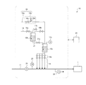
図2は、本発明の第2の実施形態に係る希釈液製造装置の概略構成図である。以下、第1の実施形態と同様の構成については、図面に同じ符号を付してその説明を省略し、第1の実施形態と異なる構成のみ説明する。
(Second Embodiment)
FIG. 2 is a schematic configuration diagram of a diluent manufacturing apparatus according to a second embodiment of the present invention. Hereinafter, the same configurations as those of the first embodiment will be described by adding the same reference numerals to the drawings and omitting the description thereof, and only the configurations different from those of the first embodiment will be described.
本実施形態は、第2のタンク12bの機能が変更されている点で、第1の実施形態と異なっている。具体的には、第2のタンク12bが、第1のタンク12aと並列にではなく、接続ライン31を介して直列に接続され、より具体的には、第2のタンク12b内の第2の液体が水頭圧によって第1のタンク12aに供給されるように、第1のタンク12aに接続されている。これに応じて、第1の実施形態のバルブ14a,14b,15a,15bは省略され、複数の第2の配管13が第1のタンク12aと第1の配管11との間にのみ設けられ、薬液供給ライン16が第2のタンク12bにのみ接続されている。また、圧力計19cは第1のタンク12aに設けられ、接続ライン31には、バルブ31aと、逆止弁(図示せず)とが設けられている。
The present embodiment is different from the first embodiment in that the function of the
したがって、本実施形態では、第2のタンク12bが、第1のタンク12aに補充される第2の液体を一時的に貯留する一時貯留タンクとして機能する。すなわち、希釈液が製造される通常運転時、第1のタンク12aの液位に基づいて、第2のタンク12bから第1のタンク12aに第2の液体が適宜補充され、その結果、第1のタンク12aから第1の配管11に第2の液体が継続的に供給される。これにより、タンクの交換作業が不要になり、装置の運転を停止する必要がなくなることで、希釈液の製造を継続的に安定して行うことが可能になる。以下、この補充動作について説明する。
Therefore, in the present embodiment, the
通常運転時、第1のタンク12aにタンク加圧用ガス供給ライン18aを通じてタンク加圧用ガス(例えば、窒素ガス)が導入され、圧力計19cによる測定値(第1のタンク12a内の圧力)が給排気機構18bによって目標圧力になるように調整される。こうして、第1のタンク12a内の第2の液体が、指定された第2の配管13を通じて所定の添加量で第1の配管11内の第1の液体に添加される。なお、このとき、タンク加圧用ガス供給ライン18aと第2のタンク12bとを接続するバルブ19b、薬液供給ライン16のバルブ16a、第2のタンク12bの大気開放バルブ17b、および接続ライン31のバルブ31aは、いずれも閉鎖された状態にある。ただし、このときの第2のタンク12bの大気開放バルブ17bの状態は、第1の実施形態と同様に、閉鎖された状態に限定されるものではなく、必要に応じて開放された状態にあってもよい。
During normal operation, the tank pressurizing gas (for example, nitrogen gas) is introduced into the
第1のタンク12aから第1の配管11に第2の液体が供給されることで、第1のタンク12a内の液位が所定の下限液位を下回ると、第2のタンク12bの大気開放バルブ17bが開放される。続いて、薬液供給ライン16のバルブ16aが開放され、薬液供給ライン16を通じて第2の液体が第2のタンク12bに供給されて貯留される。そして、第2のタンク12b内の液位が所定の上限液位に達すると、薬液供給ライン16のバルブ16aが閉鎖され、第2のタンク12bの大気開放バルブ17bが閉鎖される。その後、タンク加圧用ガス供給ライン18aと第2のタンク12bとを接続するバルブ19bが開放され、第2のタンク12bにタンク加圧用ガス供給ライン18aを通じてタンク加圧用ガスが導入される。このとき、圧力計19cによる測定値が給排気機構18bによって目標圧力になるように調整される。すなわち、第1のタンク12a内の圧力が目標圧力に調整された状態を維持しながら、第2のタンク12b内の圧力もその目標圧力になるように調整される。第2のタンク12b内の圧力がその目標圧力に達すると、接続ライン31のバルブ31aが開放されて、第2のタンク12bから第2の液体が水頭圧によって第1のタンク12aに移送される。第2の液体の移送が完了すると、接続ライン31のバルブ31aが閉鎖され、第2のタンク12bは、次回の補充動作まで待機状態になる。
When the second liquid is supplied from the
この補充動作では、上述したように、第2のタンク12bから第1のタンク12aへの第2の液体の移送は、第2のタンク12b内の圧力が第1のタンク12a内の圧力に一致するように調整された後で行われる。これにより、第2のタンク12bから第1のタンク12aに水頭圧によって第2の液体が移送される際に、第1のタンク12aの圧力変動を極力抑えることができ、製造される希釈液の濃度変動を極力抑えることができる。なお、第2のタンク12bは、第2の液体が水頭圧によって第1のタンク12aに確実に移送されるように、その底面が第1のタンク12aの天面よりも高い位置にあることが好ましい。
In this replenishment operation, as described above, in the transfer of the second liquid from the
上述した例では、第2のタンク12bへの第2の液体の貯留は、第1のタンク12a内の液位が所定の下限液位を下回った時点で開始されるが、このタイミングに限定されず、任意のタイミングで行うことができる。このとき、第2の液体が揮発性のある液体の場合、第2の液体の揮発を抑制するために、第2の液体の補充後に大気開放バルブ17bは閉鎖されたままであることが特に好ましい。同様に、第2のタンク12bから第1のタンク12aへの第2の液体の移送も、第2のタンク12bに第2の液体が貯留された後、任意のタイミングで行うことができる。ただし、第1のタンク12aが空になるまで第2の液体の供給を行うと、第2の配管にタンク加圧用ガスが溜まってしまい、そのガスが第1の配管に供給され、製造される希釈液に濃度変動が発生する可能性がある。そのため、少なくとも第2のタンク12bから第1のタンク12aへの第2の液体の移送は、第1のタンク12aから第2の液体が継続的に供給されるように、上述したタイミング、すなわち、第1のタンク12aが空になる前に開始されることが好ましい。
In the above example, the storage of the second liquid in the
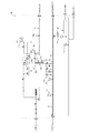
次に、図3に示すフローシートを参照して、上述した第2の実施形態に対応する実施例について説明する。図3のフローシートにおいて、図2に示す符号と同じ符号は、第2の実施形態と同様の構成を示している。 Next, an embodiment corresponding to the above-described second embodiment will be described with reference to the flow sheet shown in FIG. In the flow sheet of FIG. 3, the same reference numerals as those shown in FIG. 2 indicate the same configurations as those of the second embodiment.
(実施例1)
本実施例では、図3に示す構成の希釈液製造装置10を用いて、希釈液として希薄アンモニア水を製造し、その希薄アンモニア水の導電率を測定した。
(Example 1)
In this example, dilute ammonia water was produced as a diluent using the
第2の配管13として、内径および長さの少なくとも一方が異なる5本のETFE製チューブA〜E(チューブA,B:品番「7009」、チューブC〜E:品番「7010」、いずれもフロム社製)を用いた。各チューブA〜Eの内径および長さは、以下の通りである。
チューブA 内径:0.2mm、長さ:3m
チューブB 内径:0.2mm、長さ:1m
チューブC 内径:0.3mm、長さ:1m
チューブD 内径:0.3mm、長さ:0.5m
チューブE 内径:0.3mm、長さ:0.3m
As the
Tube A Inner diameter: 0.2 mm, length: 3 m
Tube B Inner diameter: 0.2 mm, Length: 1 m
Tube C Inner diameter: 0.3 mm, length: 1 m
Tube D Inner diameter: 0.3 mm, length: 0.5 m
Tube E Inner diameter: 0.3 mm, Length: 0.3 m
また、第1の配管11、第1のタンク12a、および第2のタンク12bとして、それぞれPFA製のものを用いた。
Further, as the
第1の液体として、比抵抗値が18MΩ・cm以上、全有機炭素(TOC)が1.0ppb以下の超純水を用い、第1の配管11には流量40L/min、水圧0.35MPaで通水させた。第2の液体として、29wt%のアンモニア水(電子工業用、関東化学(株)製)を用い、第1のタンク12aに導入するタンク加圧用ガスとしては、窒素ガスを用いた。
As the first liquid, ultrapure water having a specific resistance value of 18 MΩ · cm or more and a total organic carbon (TOC) of 1.0 ppb or less is used, and the
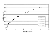
それぞれのチューブA〜Eに対して、第1のタンク12a内の圧力を変化させ、超純水に添加するアンモニア水の添加量を変化させたときの、希薄アンモニア水の導電率を、導電率計(品番「M300」、メトラー・トレド社製)を用いて測定した。図4は、このときの測定結果を示すグラフであり、横軸が超純水へのアンモニア水の添加量を示し、縦軸が得られた希釈液(希薄アンモニア水)の導電率を示している。
For each of the tubes A to E, the conductivity of the dilute ammonia water when the pressure in the
アンモニア水は弱塩基であり、低濃度域では添加量に対する導電率の変化は大きいが、高濃度域では添加量に対する導電率の変化が鈍くなる。そのため、チューブAでのアンモニア水の最小添加量およびそのときの希釈液の導電率はそれぞれ、0.015mL/minおよび1.2μS/cmであるのに対し、チューブEでのアンモニア水の最大添加量およびそのときの希釈液の導電率はそれぞれ、8.18mL/minおよび62.1μS/cmであった。すなわち、希釈液の導電率を1.2μS/cm(チューブA)から62.1μS/cm(チューブE)まで約50倍に高めるためには、アンモニア水の添加量を0.015mL/min(チューブA)から8.18mL/min(チューブE)まで約545倍も変化させる必要があった。このようなアンモニア水の添加量の調整範囲に対しても、図4のグラフからも分かるように、内径および長さの少なくとも一方が異なる5本のチューブを用いることで対応することができ、幅広い濃度範囲の希薄アンモニア水を連続して製造できることが確認された。 Ammonia water is a weak base, and the change in conductivity with respect to the amount added is large in the low concentration range, but the change in conductivity with respect to the amount added becomes slow in the high concentration range. Therefore, the minimum amount of ammonia water added in tube A and the conductivity of the diluted solution at that time are 0.015 mL / min and 1.2 μS / cm, respectively, whereas the maximum addition of ammonia water in tube E. The amount and the conductivity of the diluent at that time were 8.18 mL / min and 62.1 μS / cm, respectively. That is, in order to increase the conductivity of the diluent from 1.2 μS / cm (tube A) to 62.1 μS / cm (tube E) about 50 times, the amount of ammonia water added should be 0.015 mL / min (tube). It was necessary to change from A) to 8.18 mL / min (tube E) by about 545 times. As can be seen from the graph of FIG. 4, it is possible to cope with such an adjustment range of the amount of ammonia water added by using five tubes having different inner diameters and at least one length, which is wide. It was confirmed that dilute ammonia water in the concentration range can be continuously produced.
(実施例2)
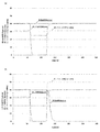
本実施例では、図3に示す構成の希釈液製造装置10を用い、第1の液体としての超純水を第1の配管11に水圧0.16MPaで通水させた点を除いて、実施例1と同様の条件で希薄アンモニア水を製造した。そして、第1の液体の供給を一時的に停止、すなわち、希釈液の製造を一時的に停止し、その前後での希薄アンモニア水の導電率を測定した。なお、超純水およびアンモニア水の温度を23℃に調整し、希釈液の導電率の目標値を40μS/cmに設定した。このときの測定結果を図5(a)に示す。なお、図5(b)には、比較例として、第1の液体の供給を一時的に停止した際に第1のタンク12a内の圧力を大気圧に戻した場合の測定結果も示している。
(Example 2)
In this embodiment, the
本実施例では、図5(a)に示すように、第1の液体の供給再開後(通常運転再開後)にも希釈液の導電率が良好に調整されていることが確認された。一方で、比較例では、図5(b)に示すように、第1の液体の供給を一時的に停止した際に第1のタンク12a内の圧力を大気圧に戻したことで、通常運転再開後に第1のタンク12a内の圧力を以前よりも高くしているにもかかわらず、希釈液の導電率の調整を良好に行うことができなかった。これは、本実施例において、第1の液体の供給を一時的に停止した際に第1のタンク12a内の圧力が大気圧を上回る圧力に保持されたことで気泡の生成が抑制されたためであると考えられる。
In this example, as shown in FIG. 5A, it was confirmed that the conductivity of the diluent was satisfactorily adjusted even after the supply of the first liquid was restarted (after the normal operation was restarted). On the other hand, in the comparative example, as shown in FIG. 5B, the pressure in the
1 ユースポイント
10 希釈液製造装置
11 第1の配管
12a 第1のタンク
12b 第2のタンク
13 第2の配管
13a バルブ
14a,14b バルブ
15a,15b バルブ
16 薬液供給ライン(液体供給手段)
16a バルブ
17a,17b 大気開放バルブ
18 圧力調整部
18a タンク加圧用ガス供給ライン
18b 給排気機構
19a,19b バルブ
19c 圧力計
20 制御部
21 流量測定手段
22 濃度測定手段
23 圧力測定手段
1 Use
Claims (9)
前記第1の液体を供給する第1の配管と、
前記第2の液体を貯留するタンクと、
前記タンクと前記第1の配管とを接続し、互いに並列に接続された複数の第2の配管と、
前記タンク内の圧力を調整する圧力調整部であって、前記タンク内の前記第2の液体を前記複数の第2の配管の少なくとも1つを通じて圧送して前記第1の配管に供給する圧力調整部と、
前記第1の配管内を流れる前記第1の液体または前記希釈液の流量と前記希釈液の濃度との測定値に基づいて、前記希釈液の濃度が所定の濃度になるように、前記圧力調整部による前記第1の液体への前記第2の液体の添加量を調整する制御部と、を有し、
前記複数の第2の配管は、内径および長さの少なくとも一方が互いに異なる、希釈液製造装置。 A diluent manufacturing apparatus for producing a diluent of the second liquid by adding a second liquid to the first liquid and supplying the diluent to a point of use.
The first pipe for supplying the first liquid and
The tank for storing the second liquid and
A plurality of second pipes connecting the tank and the first pipe and connected in parallel with each other,
A pressure adjusting unit for adjusting the pressure in the tank, which is a pressure adjusting unit for pressure-feeding the second liquid in the tank through at least one of the plurality of second pipes and supplying the second liquid to the first pipe. Department and
The pressure is adjusted so that the concentration of the diluent becomes a predetermined concentration based on the measured values of the flow rate of the first liquid or the diluent flowing in the first pipe and the concentration of the diluent. It has a control unit for adjusting the amount of the second liquid added to the first liquid by the unit.
The plurality of second pipes are diluent production devices in which at least one of the inner diameter and the length is different from each other.
前記制御部は、前記タンク内の液位が所定の下限液位を下回った場合に、前記圧力調整部によって前記別のタンク内の圧力を前記タンク内の圧力に一致させるように調整した後、前記別のタンクから前記タンクへの前記第2の液体の補充を実行する、請求項3に記載の希釈液製造装置。 The pressure adjusting unit can adjust the pressure in the other tank.
When the liquid level in the tank falls below a predetermined lower limit liquid level, the control unit adjusts the pressure in the other tank to match the pressure in the tank by the pressure adjusting unit, and then adjusts the pressure in the other tank to match the pressure in the tank. The diluent manufacturing apparatus according to claim 3, wherein the tank is refilled with the second liquid from the other tank.
前記制御部は、前記タンク内の液位が所定の下限液位を下回った場合に、前記圧力調整部によって前記別のタンク内の圧力を前記タンク内の圧力に一致させるように調整した後、前記タンクから前記第1の配管への前記第2の液体の供給を、前記別のタンクから前記第1の配管への前記第2の液体の供給に切り替える、請求項6に記載の希釈液製造装置。 The pressure adjusting unit can adjust the pressure in the other tank.
When the liquid level in the tank falls below a predetermined lower limit liquid level, the control unit adjusts the pressure in the other tank to match the pressure in the tank by the pressure adjusting unit, and then adjusts the pressure in the other tank to match the pressure in the tank. The diluted solution production according to claim 6, wherein the supply of the second liquid from the tank to the first pipe is switched to the supply of the second liquid from the other tank to the first pipe. apparatus.
第1の配管に前記第1の液体を供給する工程と、
前記第2の液体を貯留する第1のタンク内の圧力を調整して、前記第1のタンクと前記第1の配管とを接続し互いに並列に接続された複数の第2の配管の少なくとも1つを通じて、前記第1のタンク内の前記第2の液体を圧送して前記第1の配管に供給する工程であって、前記第1の配管内を流れる前記第1の液体または前記希釈液の流量と前記希釈液の濃度とを測定し、該測定値に基づいて、前記希釈液の濃度が所定の濃度になるように前記第1の液体への前記第2の液体の添加量を調整することを含む、前記第2の液体を前記第1の配管に供給する工程と、を含み、
前記第2の液体を前記第1の配管に供給する工程が、内径および長さの少なくとも一方が互いに異なる前記複数の第2の配管の少なくとも1つを通じて前記第2の液体を圧送することを含む、希釈液製造方法。 A method for producing a diluent, which comprises adding a second liquid to a first liquid to produce a diluent of the second liquid, and supplying the diluent to a point of use.
The process of supplying the first liquid to the first pipe and
At least one of a plurality of second pipes connecting the first tank and the first pipe and connected in parallel with each other by adjusting the pressure in the first tank for storing the second liquid. This is a step of pumping the second liquid in the first tank and supplying it to the first pipe through the first liquid or the diluted liquid flowing in the first pipe. The flow rate and the concentration of the diluent are measured, and the amount of the second liquid added to the first liquid is adjusted based on the measured values so that the concentration of the diluent becomes a predetermined concentration. The step of supplying the second liquid to the first pipe, including the above.
The step of supplying the second liquid to the first pipe includes pumping the second liquid through at least one of the plurality of second pipes having at least one of the inner diameter and the length different from each other. , Diluted liquid production method.
Priority Applications (5)
| Application Number | Priority Date | Filing Date | Title |
|---|---|---|---|
| JP2016254939A JP6777534B2 (en) | 2016-12-28 | 2016-12-28 | Diluting solution manufacturing equipment and diluent manufacturing method |
| PCT/JP2017/036436 WO2018123193A1 (en) | 2016-12-28 | 2017-10-06 | Device for manufacturing diluted liquid, and method for manufacturing diluted liquid |
| CN201780066541.6A CN109890494B (en) | 2016-12-28 | 2017-10-06 | Diluent production device and diluent production method |
| KR1020197015953A KR102275626B1 (en) | 2016-12-28 | 2017-10-06 | Diluent manufacturing apparatus and diluent manufacturing method |
| TW106143852A TWI759381B (en) | 2016-12-28 | 2017-12-14 | Diluted solution producing device and diluted solution producing method |
Applications Claiming Priority (1)
| Application Number | Priority Date | Filing Date | Title |
|---|---|---|---|
| JP2016254939A JP6777534B2 (en) | 2016-12-28 | 2016-12-28 | Diluting solution manufacturing equipment and diluent manufacturing method |
Publications (2)
| Publication Number | Publication Date |
|---|---|
| JP2018103147A JP2018103147A (en) | 2018-07-05 |
| JP6777534B2 true JP6777534B2 (en) | 2020-10-28 |
Family
ID=62784948
Family Applications (1)
| Application Number | Title | Priority Date | Filing Date |
|---|---|---|---|
| JP2016254939A Active JP6777534B2 (en) | 2016-12-28 | 2016-12-28 | Diluting solution manufacturing equipment and diluent manufacturing method |
Country Status (1)
| Country | Link |
|---|---|
| JP (1) | JP6777534B2 (en) |
Families Citing this family (2)
| Publication number | Priority date | Publication date | Assignee | Title |
|---|---|---|---|---|
| JP6777533B2 (en) * | 2016-12-28 | 2020-10-28 | オルガノ株式会社 | Diluting solution manufacturing equipment and diluent manufacturing method |
| JP7237785B2 (en) * | 2019-09-20 | 2023-03-13 | 株式会社東芝 | Semiconductor device manufacturing method |
Family Cites Families (6)
| Publication number | Priority date | Publication date | Assignee | Title |
|---|---|---|---|---|
| JP3723658B2 (en) * | 1997-03-21 | 2005-12-07 | 日機装株式会社 | Automatic diluter |
| JP4135780B2 (en) * | 1997-08-29 | 2008-08-20 | ユーシーティー株式会社 | Chemical solution metering apparatus and method |
| JP2005175183A (en) * | 2003-12-11 | 2005-06-30 | Kitz Sct:Kk | Liquid-pressurizing mechanism, and apparatus and method for controlling liquid using it |
| JP6233644B2 (en) * | 2014-02-24 | 2017-11-22 | スガ試験機株式会社 | Weather resistance tester and diluted solution supply device |
| KR101943238B1 (en) * | 2014-09-16 | 2019-01-28 | 오르가노 코포레이션 | Diluted liquid production method and diluted liquid production device |
| JP6777533B2 (en) * | 2016-12-28 | 2020-10-28 | オルガノ株式会社 | Diluting solution manufacturing equipment and diluent manufacturing method |
-
2016
- 2016-12-28 JP JP2016254939A patent/JP6777534B2/en active Active
Also Published As
| Publication number | Publication date |
|---|---|
| JP2018103147A (en) | 2018-07-05 |
Similar Documents
| Publication | Publication Date | Title |
|---|---|---|
| US10857512B2 (en) | Diluted solution production method and diluted solution production apparatus | |
| CN102036742B (en) | Gasification system and method for preparing bubble-free solutions of gas in liquid | |
| US8448925B2 (en) | Devices, systems, and methods for carbonation of deionized water | |
| TWI759381B (en) | Diluted solution producing device and diluted solution producing method | |
| US20200353431A1 (en) | Functional water producing apparatus and functional water producing method | |
| WO2018190090A1 (en) | Cleaning water supply device | |
| US20240025785A1 (en) | Production device for ph/redox potential-adjusted water | |
| JP2018022749A (en) | Apparatus and method for producing alkaline water for cleaning electronic devices | |
| JP2018206998A (en) | Diluted chemical solution manufacturing apparatus | |
| JP6777534B2 (en) | Diluting solution manufacturing equipment and diluent manufacturing method | |
| JP6777533B2 (en) | Diluting solution manufacturing equipment and diluent manufacturing method | |
| JP6738726B2 (en) | Diluting liquid manufacturing apparatus and diluting liquid manufacturing method | |
| JP2005175183A (en) | Liquid-pressurizing mechanism, and apparatus and method for controlling liquid using it | |
| JP7049875B2 (en) | Diluted liquid manufacturing method and diluted liquid manufacturing equipment | |
| TWI842869B (en) | System for supplying a rinsing liquid comprising ultrapure water and an ammonia gas and method for supplying a rinsing liquid comprising ultrapure water with a desired concentration of an ammonia gas dissolved therein | |
| JP2020179372A (en) | Gas dissolution water manufacturing apparatus and method |
Legal Events
| Date | Code | Title | Description |
|---|---|---|---|
| A621 | Written request for application examination |
Free format text: JAPANESE INTERMEDIATE CODE: A621 Effective date: 20190917 |
|
| A131 | Notification of reasons for refusal |
Free format text: JAPANESE INTERMEDIATE CODE: A132 Effective date: 20200707 |
|
| TRDD | Decision of grant or rejection written | ||
| A01 | Written decision to grant a patent or to grant a registration (utility model) |
Free format text: JAPANESE INTERMEDIATE CODE: A01 Effective date: 20200924 |
|
| A61 | First payment of annual fees (during grant procedure) |
Free format text: JAPANESE INTERMEDIATE CODE: A61 Effective date: 20201008 |
|
| R150 | Certificate of patent or registration of utility model |
Ref document number: 6777534 Country of ref document: JP Free format text: JAPANESE INTERMEDIATE CODE: R150 |
|
| R250 | Receipt of annual fees |
Free format text: JAPANESE INTERMEDIATE CODE: R250 |
|
| R250 | Receipt of annual fees |
Free format text: JAPANESE INTERMEDIATE CODE: R250 |
|
| R250 | Receipt of annual fees |
Free format text: JAPANESE INTERMEDIATE CODE: R250 |