JP6776541B2 - Printing device and compression method of printing medium - Google Patents
Printing device and compression method of printing medium Download PDFInfo
- Publication number
- JP6776541B2 JP6776541B2 JP2016009510A JP2016009510A JP6776541B2 JP 6776541 B2 JP6776541 B2 JP 6776541B2 JP 2016009510 A JP2016009510 A JP 2016009510A JP 2016009510 A JP2016009510 A JP 2016009510A JP 6776541 B2 JP6776541 B2 JP 6776541B2
- Authority
- JP
- Japan
- Prior art keywords
- medium
- printing
- pressing
- print medium
- unit
- Prior art date
- Legal status (The legal status is an assumption and is not a legal conclusion. Google has not performed a legal analysis and makes no representation as to the accuracy of the status listed.)
- Active
Links
Images


Classifications
-
- B—PERFORMING OPERATIONS; TRANSPORTING
- B41—PRINTING; LINING MACHINES; TYPEWRITERS; STAMPS
- B41J—TYPEWRITERS; SELECTIVE PRINTING MECHANISMS, i.e. MECHANISMS PRINTING OTHERWISE THAN FROM A FORME; CORRECTION OF TYPOGRAPHICAL ERRORS
- B41J11/00—Devices or arrangements of selective printing mechanisms, e.g. ink-jet printers or thermal printers, for supporting or handling copy material in sheet or web form
- B41J11/0045—Guides for printing material
- B41J11/005—Guides in the printing zone, e.g. guides for preventing contact of conveyed sheets with printhead
-
- B—PERFORMING OPERATIONS; TRANSPORTING
- B41—PRINTING; LINING MACHINES; TYPEWRITERS; STAMPS
- B41J—TYPEWRITERS; SELECTIVE PRINTING MECHANISMS, i.e. MECHANISMS PRINTING OTHERWISE THAN FROM A FORME; CORRECTION OF TYPOGRAPHICAL ERRORS
- B41J11/00—Devices or arrangements of selective printing mechanisms, e.g. ink-jet printers or thermal printers, for supporting or handling copy material in sheet or web form
- B41J11/0015—Devices or arrangements of selective printing mechanisms, e.g. ink-jet printers or thermal printers, for supporting or handling copy material in sheet or web form for treating before, during or after printing or for uniform coating or laminating the copy material before or after printing
- B41J11/002—Curing or drying the ink on the copy materials, e.g. by heating or irradiating
- B41J11/0021—Curing or drying the ink on the copy materials, e.g. by heating or irradiating using irradiation
- B41J11/00216—Curing or drying the ink on the copy materials, e.g. by heating or irradiating using irradiation using infrared [IR] radiation or microwaves
-
- B—PERFORMING OPERATIONS; TRANSPORTING
- B41—PRINTING; LINING MACHINES; TYPEWRITERS; STAMPS
- B41J—TYPEWRITERS; SELECTIVE PRINTING MECHANISMS, i.e. MECHANISMS PRINTING OTHERWISE THAN FROM A FORME; CORRECTION OF TYPOGRAPHICAL ERRORS
- B41J11/00—Devices or arrangements of selective printing mechanisms, e.g. ink-jet printers or thermal printers, for supporting or handling copy material in sheet or web form
- B41J11/0005—Curl smoothing, i.e. smoothing down corrugated printing material, e.g. by pressing means acting on wrinkled printing material
-
- B—PERFORMING OPERATIONS; TRANSPORTING
- B41—PRINTING; LINING MACHINES; TYPEWRITERS; STAMPS
- B41J—TYPEWRITERS; SELECTIVE PRINTING MECHANISMS, i.e. MECHANISMS PRINTING OTHERWISE THAN FROM A FORME; CORRECTION OF TYPOGRAPHICAL ERRORS
- B41J11/00—Devices or arrangements of selective printing mechanisms, e.g. ink-jet printers or thermal printers, for supporting or handling copy material in sheet or web form
- B41J11/0015—Devices or arrangements of selective printing mechanisms, e.g. ink-jet printers or thermal printers, for supporting or handling copy material in sheet or web form for treating before, during or after printing or for uniform coating or laminating the copy material before or after printing
- B41J11/002—Curing or drying the ink on the copy materials, e.g. by heating or irradiating
- B41J11/0021—Curing or drying the ink on the copy materials, e.g. by heating or irradiating using irradiation
- B41J11/00212—Controlling the irradiation means, e.g. image-based controlling of the irradiation zone or control of the duration or intensity of the irradiation
-
- B—PERFORMING OPERATIONS; TRANSPORTING
- B41—PRINTING; LINING MACHINES; TYPEWRITERS; STAMPS
- B41J—TYPEWRITERS; SELECTIVE PRINTING MECHANISMS, i.e. MECHANISMS PRINTING OTHERWISE THAN FROM A FORME; CORRECTION OF TYPOGRAPHICAL ERRORS
- B41J11/00—Devices or arrangements of selective printing mechanisms, e.g. ink-jet printers or thermal printers, for supporting or handling copy material in sheet or web form
- B41J11/02—Platens
- B41J11/04—Roller platens
-
- B—PERFORMING OPERATIONS; TRANSPORTING
- B41—PRINTING; LINING MACHINES; TYPEWRITERS; STAMPS
- B41J—TYPEWRITERS; SELECTIVE PRINTING MECHANISMS, i.e. MECHANISMS PRINTING OTHERWISE THAN FROM A FORME; CORRECTION OF TYPOGRAPHICAL ERRORS
- B41J13/00—Devices or arrangements of selective printing mechanisms, e.g. ink-jet printers or thermal printers, specially adapted for supporting or handling copy material in short lengths, e.g. sheets
- B41J13/0009—Devices or arrangements of selective printing mechanisms, e.g. ink-jet printers or thermal printers, specially adapted for supporting or handling copy material in short lengths, e.g. sheets control of the transport of the copy material
-
- B—PERFORMING OPERATIONS; TRANSPORTING
- B41—PRINTING; LINING MACHINES; TYPEWRITERS; STAMPS
- B41J—TYPEWRITERS; SELECTIVE PRINTING MECHANISMS, i.e. MECHANISMS PRINTING OTHERWISE THAN FROM A FORME; CORRECTION OF TYPOGRAPHICAL ERRORS
- B41J15/00—Devices or arrangements of selective printing mechanisms, e.g. ink-jet printers or thermal printers, specially adapted for supporting or handling copy material in continuous form, e.g. webs
- B41J15/04—Supporting, feeding, or guiding devices; Mountings for web rolls or spindles
- B41J15/048—Conveyor belts or like feeding devices
-
- B—PERFORMING OPERATIONS; TRANSPORTING
- B41—PRINTING; LINING MACHINES; TYPEWRITERS; STAMPS
- B41J—TYPEWRITERS; SELECTIVE PRINTING MECHANISMS, i.e. MECHANISMS PRINTING OTHERWISE THAN FROM A FORME; CORRECTION OF TYPOGRAPHICAL ERRORS
- B41J3/00—Typewriters or selective printing or marking mechanisms characterised by the purpose for which they are constructed
- B41J3/407—Typewriters or selective printing or marking mechanisms characterised by the purpose for which they are constructed for marking on special material
- B41J3/4078—Printing on textile
Description
本発明は、印刷装置、及び印刷媒体の圧縮方法に関する。 The present invention relates to a printing apparatus and a method for compressing a printing medium.
従来から、ノズルを有する吐出ヘッドから印刷媒体の表面に向かってインクなどの液体を液滴に吐出し印刷媒体に画像などを印刷するインクジェット方式の印刷装置が使用されている。このような印刷装置の印刷媒体に、表面が毛羽立っている布帛などを用いる場合には、毛羽と吐出ヘッドとの接触や、遊離した毛羽が吐出ヘッドに付着することによる印刷品質の低下を未然に防止するために、印刷直前に毛羽を処理することが望ましい。毛羽処理の方法としては、例えば、特許文献1に開示されている、毛羽層にレーザー光線を照射し、毛羽層を熱溶融させる方法がある。
Conventionally, an inkjet printing device has been used in which a liquid such as ink is ejected into droplets from an ejection head having a nozzle toward the surface of a printing medium to print an image or the like on the printing medium. When a cloth having a fluffy surface is used as the printing medium of such a printing apparatus, the print quality is deteriorated due to the contact between the fluff and the ejection head and the loose fluff adhering to the ejection head. To prevent it, it is desirable to treat the fluff just before printing. As a method of fluff treatment, for example, there is a method disclosed in
特許文献1に記載されている毛羽処理は、毛羽にレーザー光線を照射するためのレーザー照射装置を必要とする。しかしながら、印刷装置にレーザー照射装置を備えるのは、装置のコスト上昇と安全上の問題とにより困難であった。また、毛羽と吐出ヘッドとが接触しないように、印刷媒体に対して吐出ヘッドを高くして印刷させた場合には、液滴の着弾ずれが大きくなって画像が不鮮明になってしまうという問題があった。したがって、依然として毛羽立っている印刷媒体上に印刷品質の優れた画像を形成させる印刷装置を提供することが困難であった。
The fluff treatment described in
本発明は、上述の課題の少なくとも一部を解決するためになされたものであり、以下の形態又は適用例として実現することが可能である。 The present invention has been made to solve at least a part of the above-mentioned problems, and can be realized as the following forms or application examples.
[適用例1]本適用例に係る印刷装置は、無端ベルトに載置された印刷媒体に液体を吐出する吐出ヘッドと、前記印刷媒体を搬送方向に搬送させる搬送手段と、前記搬送方向において前記吐出ヘッドより上流側に設けられ前記印刷媒体を圧縮させる媒体押圧手段を有する媒体プレス部と、前記媒体プレス部を制御する制御部と、を備えていること、を特徴とする。 [Application Example 1] The printing apparatus according to this application example includes a discharge head that discharges liquid to a print medium mounted on an endless belt, a transfer means that conveys the print medium in a transfer direction, and the above in the transfer direction. It is characterized by including a medium press unit provided on the upstream side of the discharge head and having a medium pressing means for compressing the print medium, and a control unit for controlling the medium press unit.
本適用例によれば、印刷装置は、搬送手段によって搬送されてくる印刷媒体を圧縮させる媒体プレス部を備えている。毛羽を有する印刷媒体は、媒体押圧手段の押圧力によって毛羽の高さが低くなるので、吐出ヘッドと印刷媒体との接触機会が低減され、吐出ヘッドと毛羽とが接触することで生じるノズル抜けや着弾ずれなどの不具合が生じ難くなる。また、圧縮後の印刷媒体(毛羽)の高さに合わせて、吐出ヘッドを低く設定することができる。これにより、毛羽立っている印刷媒体上に印刷品質の優れた画像が形成される。したがって、印刷品質を向上させた印刷装置を提供することができる。 According to this application example, the printing apparatus includes a medium press unit that compresses the print medium conveyed by the conveying means. In a printing medium having fluff, the height of the fluff is lowered by the pressing force of the medium pressing means, so that the chance of contact between the ejection head and the printing medium is reduced, and nozzle omission caused by contact between the ejection head and the fluff occurs. Problems such as landing deviation are less likely to occur. Further, the ejection head can be set low according to the height of the printed medium (fluff) after compression. As a result, an image having excellent print quality is formed on the fluffy print medium. Therefore, it is possible to provide a printing apparatus with improved print quality.
[適用例2]上記適用例に記載の印刷装置は、前記印刷媒体の種類を含む印刷条件が入力される入力手段を備え、前記制御部は、前記印刷条件に応じて前記媒体押圧手段の押圧力を変更可能に制御すること、が好ましい。 [Application Example 2] The printing apparatus according to the above application example includes input means for inputting printing conditions including the type of the printing medium, and the control unit presses the medium pressing means according to the printing conditions. It is preferable to control the pressure in a changeable manner.
本適用例によれば、印刷媒体の毛羽の量(密度)や長さは、印刷媒体の種類によって異なるが、本適用例の印刷装置は、入力手段に入力された印刷媒体の種類に応じて、印刷媒体を圧縮させる際の媒体押圧手段の押圧力が制御部によって変更可能に制御されるので、印刷媒体を好適に圧縮することができる。 According to this application example, the amount (density) and length of fluff of the print medium differ depending on the type of print medium, but the printing apparatus of this application example depends on the type of print medium input to the input means. Since the pressing force of the medium pressing means when compressing the print medium is controllably controlled by the control unit, the print medium can be suitably compressed.
[適用例3]上記適用例に記載の印刷装置において、前記媒体プレス部は、前記印刷媒体を加熱する媒体加熱手段を有し、前記制御部は、前記印刷条件に応じて前記媒体加熱手段の温度を変更可能に制御すること、が好ましい。 [Application Example 3] In the printing apparatus according to the above application example, the medium pressing unit has a medium heating means for heating the printing medium, and the control unit has the medium heating means according to the printing conditions. It is preferable to control the temperature so as to be changeable.
本適用例によれば、媒体プレス部は、印刷媒体を圧縮する際に印刷媒体を加熱する媒体加熱手段を有しているので、印刷媒体の圧縮効率を向上させることができる。また、印刷媒体に加えることができる温度は、印刷媒体の種類(材質)によって異なるが、本適用例の印刷装置は、媒体加熱手段の温度が制御部によって変更可能に制御されるので、異なる材質の印刷媒体を好適に圧縮することができる。 According to this application example, since the medium press unit has a medium heating means for heating the print medium when the print medium is compressed, the compression efficiency of the print medium can be improved. The temperature that can be applied to the print medium differs depending on the type (material) of the print medium, but the printing apparatus of this application example has a different material because the temperature of the medium heating means is controllably controlled by the control unit. The print medium can be suitably compressed.
[適用例4]上記適用例に記載の印刷装置において、前記印刷条件は、前記無端ベルトと前記吐出ヘッドとの間の距離を含み、前記制御部は、前記印刷条件に応じて前記押圧力及び前記温度のうちの少なくとも一方を変更可能に制御すること、が好ましい。 [Application Example 4] In the printing apparatus according to the above application example, the printing condition includes the distance between the endless belt and the discharge head, and the control unit controls the pressing force and the pressing force according to the printing condition. It is preferable to control at least one of the above temperatures in a changeable manner.
本適用例によれば、印刷装置は、無端ベルトと吐出ヘッドとの間の距離、印刷媒体の種類を含む印刷条件に応じて、印刷媒体を圧縮させる際に加える媒体押圧手段の押圧力及び媒体加熱手段の温度のうちの少なくとも一方が制御部によって変更可能に制御される。これにより、入力された無端ベルトと吐出ヘッドとの間の距離に適した高さに印刷媒体を圧縮することができる。 According to this application example, in the printing apparatus, the pressing force of the medium pressing means applied when compressing the printing medium and the medium are applied according to the printing conditions including the distance between the endless belt and the ejection head and the type of the printing medium. At least one of the temperatures of the heating means is mutably controlled by the control unit. As a result, the print medium can be compressed to a height suitable for the distance between the input endless belt and the ejection head.
[適用例5]上記適用例に記載の印刷装置は、入力された前記印刷条件に応じて警報を報知する報知部を備えていること、が好ましい。 [Application Example 5] It is preferable that the printing apparatus described in the above application example includes a notification unit that notifies an alarm according to the input printing conditions.
本適用例によれば、印刷装置は、例えば、入力された印刷媒体と吐出ヘッドとの間の距離を含む印刷条件にて、印刷媒体の高さを印刷媒体と吐出ヘッドとの間の距離よりも低く圧縮させることができない場合などに、警報を報知する報知部を備えている。これにより、画像品質の劣化した印刷が行われることを事前に防止することができる。 According to this application example, the printing apparatus sets the height of the printing medium from the distance between the printing medium and the ejection head under printing conditions including, for example, the distance between the input printing medium and the ejection head. It is equipped with a notification unit that notifies an alarm when it cannot be compressed low. As a result, it is possible to prevent printing with deteriorated image quality from being performed in advance.
[適用例6]本適用例に係る印刷媒体の圧縮方法は、無端ベルトに載置された印刷媒体に液体を吐出する吐出ヘッドと、前記印刷媒体を搬送方向に搬送させる搬送手段と、前記搬送方向において前記吐出ヘッドより上流側に設けられ前記印刷媒体を圧縮させる媒体押圧手段を有する媒体プレス部と、印刷条件が入力される入力手段と、前記媒体プレス部を制御する制御部と、を備えた印刷装置における印刷媒体の圧縮方法であって、前記印刷条件に応じて、印刷媒体を圧縮する際の条件を求める圧縮条件決定工程と、前記印刷媒体を圧縮する媒体圧縮工程と、を含んでいること、を特徴とする。 [Application Example 6] The printing medium compression method according to the present application example includes a discharge head that discharges liquid to a print medium mounted on an endless belt, a transport means that transports the print medium in a transport direction, and the transport. A medium press unit provided upstream of the discharge head in the direction and having a medium pressing unit for compressing the print medium, an input means for inputting printing conditions, and a control unit for controlling the medium press unit are provided. A method for compressing a print medium in a printing apparatus, which includes a compression condition determination step for obtaining conditions for compressing the print medium according to the print conditions, and a medium compression step for compressing the print medium. It is characterized by being.
本適用例によれば、印刷媒体の圧縮方法は、入力手段に入力された印刷条件に応じて、印刷媒体を圧縮する際の条件を求める圧縮条件決定工程と、印刷媒体を圧縮する媒体圧縮工程と、を含んでいる。毛羽を有する印刷媒体は、これらの工程によって毛羽が圧縮され、印刷媒体の高さが低くなるので、吐出ヘッドと印刷媒体との接触機会が低減され、吐出ヘッドと毛羽とが接触することで生じるノズル抜けや着弾ずれなどの不具合が生じ難くなる。また、圧縮後の印刷媒体(毛羽)の高さに合わせて、吐出ヘッドを低く設定することができる。これにより、毛羽立っている印刷媒体上に印刷品質の優れた画像が形成される。したがって、印刷品質を向上させることが可能な印刷媒体の圧縮方法を提供することができる。 According to this application example, the printing medium compression method includes a compression condition determination step for obtaining conditions for compressing the print medium according to the print conditions input to the input means, and a medium compression step for compressing the print medium. And, including. In a print medium having fluff, the fluff is compressed by these steps and the height of the print medium is lowered, so that the chance of contact between the ejection head and the print medium is reduced, and the fluff comes into contact with the ejection head. Problems such as nozzle omission and landing deviation are less likely to occur. Further, the ejection head can be set low according to the height of the printed medium (fluff) after compression. As a result, an image having excellent print quality is formed on the fluffy print medium. Therefore, it is possible to provide a compression method of a print medium capable of improving print quality.
以下、本発明の実施形態について、図面を参照して説明する。なお、以下の各図においては、各層や各部材を認識可能な程度の大きさにするため、各層や各部材の尺度を実際とは異ならせている。
また、図1から図3、及び図8から図10では、説明の便宜上、互いに直交する三軸として、X軸、Y軸及びZ軸を図示しており、軸方向を図示した矢印の先端側を「+側」、基端側を「−側」としている。また、以下では、X軸に平行な方向を「X軸方向」、Y軸に平行な方向を「Y軸方向」、Z軸に平行な方向を「Z軸方向」という。
Hereinafter, embodiments of the present invention will be described with reference to the drawings. In each of the following figures, the scale of each layer and each member is different from the actual scale in order to make each layer and each member recognizable in size.
Further, in FIGS. 1 to 3 and 8 to 10, for convenience of explanation, the X-axis, the Y-axis, and the Z-axis are shown as three axes orthogonal to each other, and the tip side of the arrow showing the axial direction is shown. Is the "+ side" and the base end side is the "-side". Further, in the following, the direction parallel to the X axis is referred to as "X axis direction", the direction parallel to the Y axis is referred to as "Y axis direction", and the direction parallel to the Z axis is referred to as "Z axis direction".
(実施形態)
<印刷装置の概略構成>
図1は、実施形態に係る印刷装置の概略全体構成を示す模式図である。まず、本実施形態に係る印刷装置100の概略構成について図1を参照して説明する。なお、本実施形態では、印刷媒体95に画像などを形成することで印刷媒体95に捺染を行うインクジェット式の印刷装置100を例に上げて説明する。
(Embodiment)
<Outline configuration of printing device>
FIG. 1 is a schematic view showing a schematic overall configuration of a printing apparatus according to an embodiment. First, a schematic configuration of the
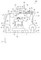
図1に示すように、印刷装置100は、媒体搬送部20、媒体プレス部70、媒体密着部60、印刷部40、乾燥ユニット27、洗浄ユニット50、及び報知部92などを備えている。そして、これらの各部を制御する制御部1を有している。印刷装置100の各部は、フレーム部90に取り付けられている。
As shown in FIG. 1, the
媒体搬送部20は、印刷媒体95を搬送方向(印刷部40において+X軸方向)に搬送する搬送手段である。媒体搬送部20は、媒体供給部10、搬送ローラー21,22,23、無端ベルト48、ベルト回転ローラー24、ベルト駆動ローラー25、搬送ローラー26,28、及び媒体回収部30を備えている。まず、媒体供給部10から媒体回収部30に至る印刷媒体95の搬送経路について説明する。
The
媒体供給部10は、画像を形成させる印刷媒体95を印刷部40側に供給するものである。印刷媒体95としては、例えば、綿、ウール、ポリエステルなどの布帛が用いられる。媒体供給部10は、供給軸部11及び軸受部12を有している。供給軸部11は、円筒状又は円柱状に形成されており、円周方向に回転可能に設けられている。供給軸部11には、帯状の印刷媒体95がロール状に巻かれている。供給軸部11は、軸受部12に対して着脱可能に取り付けられている。これにより、予め供給軸部11に巻かれた状態の印刷媒体95は、供給軸部11と共に軸受部12に取り付けできるようになっている。
The
軸受部12は、供給軸部11の軸方向の両端を回転可能に支持している。媒体供給部10は、供給軸部11を回転駆動させる回転駆動部(図示せず)を有している。回転駆動部は、印刷媒体95が送り出される方向に供給軸部11を回転させる。回転駆動部の動作は、制御部1によって制御される。搬送ローラー21,22,23は、印刷媒体95を媒体供給部10から無端ベルト48まで中継する。
The bearing
無端ベルト48、ベルト回転ローラー24及びベルト駆動ローラー25は、印刷部40において印刷媒体95を搬送方向(+X軸方向)に搬送させる。詳しくは、無端ベルト48は、帯状のベルトの両端部が接続されて無端状に形成されており、ベルト回転ローラー24及びベルト駆動ローラー25に掛けられている。無端ベルト48は、ベルト回転ローラー24とベルト駆動ローラー25との間の部分が床面99に対して平行になるように、所定の張力が作用した状態で保持されている。無端ベルト48の表面(支持面)48aには、印刷媒体95を粘着させる粘着層29が設けられている。無端ベルト48は、搬送ローラー22から供給され、後述する媒体密着部60で粘着層29に密着された印刷媒体95を支持(保持)している。これにより、伸縮性のある布帛などを印刷媒体95として扱うことができる。
The
ベルト回転ローラー24及びベルト駆動ローラー25は、無端ベルト48の内周面48bを支持する。なお、ベルト回転ローラー24とベルト駆動ローラー25との間に、無端ベルト48を支持する支持部が設けられた構成であってもよい。
The
ベルト駆動ローラー25は、ベルト駆動ローラー25を回転駆動させるモーター(図示せず)を有している。ベルト駆動ローラー25が回転駆動されるとベルト駆動ローラー25の回転に伴って無端ベルト48が回転し、無端ベルト48の回転によりベルト回転ローラー24が回転する。無端ベルト48の回転により、無端ベルト48に支持された印刷媒体95が所定の搬送方向(+X軸方向)に搬送され、後述する印刷部40で印刷媒体95に画像が形成される。
The
本実施形態では、無端ベルト48の表面48aが印刷部40と対向する側(+Z軸側)において印刷媒体95が載置され、印刷媒体95が無端ベルト48と共にベルト回転ローラー24側からベルト駆動ローラー25側に搬送される。また、無端ベルト48の表面48aが洗浄ユニット50と対向する側(−Z軸側)においては、無端ベルト48のみがベルト駆動ローラー25側からベルト回転ローラー24側に移動する。なお、無端ベルト48は、印刷媒体95を密着させる粘着層29を備えているものと説明したが、これに限定するものではない。例えば、無端ベルトは、静電気で媒体をベルトに吸着させる静電吸着式の無端ベルトであってもよい。
In the present embodiment, the
搬送ローラー26は、画像の形成された印刷媒体95を無端ベルト48の粘着層29から剥離させる。搬送ローラー26,28は、印刷媒体95を無端ベルト48から媒体回収部30まで中継する。
The
媒体回収部30は、媒体搬送部20によって搬送された印刷媒体95を回収する。媒体回収部30は、巻取り軸部31及び軸受部32を有している。巻取り軸部31は、円筒状又は円柱状に形成されており、円周方向に回転可能に設けられている。巻取り軸部31には、帯状の印刷媒体95がロール状に巻き取られている。巻取り軸部31は、軸受部32に対して着脱可能に取り付けられている。これにより、巻取り軸部31に巻き取られた状態の印刷媒体95は、巻取り軸部31と共に取り外せるようになっている。
The
軸受部32は、巻取り軸部31の軸線方向の両端を回転可能に支持している。媒体回収部30は、巻取り軸部31を回転駆動させる回転駆動部(図示せず)を有している。回転駆動部は、印刷媒体95が巻き取られる方向に巻取り軸部31を回転させる。回転駆動部の動作は、制御部1によって制御される。
The bearing
次に、媒体搬送部20に沿って設けられている各部について説明する。
媒体プレス部70は、印刷媒体95を圧縮して、印刷媒体95の高さ(厚さ)を低くさせるものである。媒体プレス部70は、搬送方向において後述する吐出ヘッド42よりも上流側の搬送ローラー22と搬送ローラー23との間に設けられている。媒体プレス部70の構成については、後で詳述する。
Next, each part provided along the
The medium
媒体密着部60は、印刷媒体95を無端ベルト48に密着させるものである。媒体密着部60は、印刷媒体95の搬送方向において媒体プレス部70の下流側(+X軸側)に位置し、印刷部40より上流側(−X軸側)に設けられている。媒体密着部60は、押圧ローラー61、押圧ローラー駆動部62及びローラー支持部63を有している。押圧ローラー61は、円筒状又は円柱状に形成されており、円周方向に回転可能に設けられている。押圧ローラー61は、搬送方向に沿った方向に回転するように、軸線方向が搬送方向と交差するように配置されている。ローラー支持部63は、無端ベルト48を挟んで押圧ローラー61と対向する無端ベルト48の内周面48b側に設けられている。
The
押圧ローラー駆動部62は、押圧ローラー61を鉛直方向の下方側(−Z軸側)に押圧しながら搬送方向(+X軸方向)、及び搬送方向と逆向きの方向(−X軸方向)に押圧ローラー61を移動させる。搬送ローラー23によって無端ベルト48に重ね合された印刷媒体95は、押圧ローラー61とローラー支持部63との間で無端ベルト48に押し当てられる。これにより、無端ベルト48の表面48aに設けられている粘着層29に印刷媒体95を確実に粘着させることができ、無端ベルト48上での印刷媒体95の浮きの発生を防止することができる。
The pressing
印刷部40は、無端ベルト48の配置位置に対して上方(+Z軸側)に配置されている。印刷部40は、無端ベルト48に載置された印刷媒体95に液体の一例としてのインクを液滴に吐出する吐出ヘッド42、吐出ヘッド42が搭載されるキャリッジ43、キャリッジ43を搬送方向と交差する印刷媒体95の幅方向(Y軸方向)に移動させるキャリッジ移動部41などを有している。吐出ヘッド42には、複数のノズル列45が形成されているノズルプレート44が備えられている。例えば、ノズルプレート44には、4つのノズル列45が形成され、ノズル列45毎に異なる色のインク(例えば、シアン:C、マゼンタ:M、イエロー:Y、ブラック:K)が吐出されるようになっている。ノズルプレート44は、無端ベルト48によって搬送される印刷媒体95と対向している。
The
キャリッジ移動部41は、印刷媒体95の搬送方向と交差する方向(印刷媒体95の幅方向(Y軸方向))に吐出ヘッド42を移動させる。キャリッジ43は、Y軸方向に沿って配置されたガイドレール(図示せず)に支持され、キャリッジ移動部41によって±Y軸方向に往復移動可能に構成されている。キャリッジ移動部41の機構としては、例えば、ボールねじとボールナットとを組み合わせた機構や、リニアガイド機構などを採用することができる。
The
さらに、キャリッジ移動部41には、キャリッジ43をY軸方向に沿って移動させるための動力源として、モーター(図示せず)が設けられている。制御部1の制御によりモーターが駆動されると、吐出ヘッド42は、キャリッジ43と共にY軸方向に沿って往復移動する。媒体搬送部20による印刷媒体95の+X軸方向への搬送と、吐出ヘッド42のY軸方向への移動とが、交互に繰り返されることにより、印刷媒体95に画像などが印刷される。なお、本実施形態では、吐出ヘッド42として、可動のキャリッジに搭載され印刷媒体95の幅方向(±Y軸方向)に移動しながらインクを吐出するシリアルヘッド式を例示したが、印刷媒体95の幅方向(Y軸方向)に延在し固定して配列されたラインヘッド式であってもよい。
Further, the
乾燥ユニット27は、搬送ローラー26と搬送ローラー28との間に設けられている。乾燥ユニット27は、印刷媒体95上に吐出されたインクを乾燥するものであり、乾燥ユニット27には、例えば、IRヒーターを含み、IRヒーターを駆動させることにより印刷媒体95上に吐出されたインクを短時間で乾燥させることができる。これにより、画像などの形成された帯状の印刷媒体95を巻取り軸部31に巻き取ることができる。
The drying
洗浄ユニット50は、X軸方向においてベルト回転ローラー24とベルト駆動ローラー25の間に配置されている。洗浄ユニット50は、無端ベルト48の表面48aを洗浄するためのものである。洗浄ユニット50は、洗浄部51、押圧部52及び移動部53を有している。移動部53は、床面99に沿って洗浄ユニット50を一体的に移動させて所定の位置に固定させる。
The
押圧部52は、例えば、エアーシリンダー56とボールブッシュ57とで構成された昇降装置であり、その上部に備えられている洗浄部51を無端ベルト48の表面48aに当接させるものである。洗浄部51は、ベルト回転ローラー24とベルト駆動ローラー25との間で所定の張力が作用した状態で掛けられている無端ベルト48の表面(支持面)48aを下方(−Z軸方向)から洗浄する。
The
洗浄部51は、洗浄槽54、洗浄ローラー58及びブレード55を有している。洗浄槽54は、無端ベルト48の表面48aに付着したインクや異物の洗浄に用いる洗浄液を貯留する槽であり、洗浄ローラー58及びブレード55は洗浄槽54の内側に設けられている。洗浄液としては、例えば、水や水溶性溶剤(アルコール水溶液など)を用いることができ、必要に応じて界面活性剤や消泡剤を添加させてもよい。
The
洗浄ローラー58が回転すると、洗浄液が無端ベルト48の表面48aに供給されると共に、洗浄ローラー58と無端ベルト48とが摺動する。これにより、無端ベルト48に付着したインクや印刷媒体95としての布帛の繊維などが洗浄ローラー58で取り除かれる。
When the cleaning
ブレード55は、例えば、シリコンゴムなどの可撓性の材料で形成することができる。ブレード55は、無端ベルト48の搬送方向において洗浄ローラー58よりも下流側に設けられている。無端ベルト48とブレード55とが摺動することにより、無端ベルト48の表面48aに残っている洗浄液が除去される。
The
印刷装置100は、警報を報知する報知部92を備えている。本実施形態の報知部92は、所謂パトライト(登録商標)であり、制御部1の制御により印刷装置100の状態を色や点滅パターンなどにより報知する。なお、報知部は、液晶パネルなどで構成された表示装置であって、報知内容を文字や図形で表示させるものであってもよい。
The
<媒体プレス部の構成>
次に、媒体プレス部の構成について説明する。
図2は、媒体プレス部の構成を示す断面図である。図3は、媒体プレス部の構成を示す側面図である。
<Composition of media press section>
Next, the configuration of the medium press unit will be described.
FIG. 2 is a cross-sectional view showing the configuration of the medium press unit. FIG. 3 is a side view showing the configuration of the medium press unit.
図2及び図3に示すように、媒体プレス部70は、印刷媒体95の上側(+Z軸側)に位置する第1回転ローラー71と、印刷媒体95の下側(−Z軸側)に位置する第2回転ローラー72などを有している。
第1回転ローラー71は、印刷媒体95の幅よりも長い円柱の形状をなし、回転軸71aを中心に回転する。第2回転ローラー72は、印刷媒体95の幅よりも長い円柱の形状をなし、回転軸72aを中心に回転する。第2回転ローラー72は、第1回転ローラー71と対向して設けられ、印刷媒体95は、第1、第2回転ローラー71,72によって挟持される。
As shown in FIGS. 2 and 3, the
The first
回転軸71a,72aは、X軸方向からの側面視にて、印刷媒体95の外側に立設しているフレーム部90a,90bの間に回転可能に支持されている。媒体プレス部70は、回転軸71aを回転駆動させる回転駆動モーター78を有している。回転駆動モーター78は、印刷媒体95を搬送させる媒体搬送部20の駆動と同期して第1回転ローラー71を回転させる。第1回転ローラー71は、図2において右回りに回転する。第2回転ローラー72は、印刷媒体95を介して第1回転ローラー71の回転に従動し、第1回転ローラーの回転方向と逆向きに回転する。回転駆動モーター78の動作は、制御部1によって制御される。
The
媒体プレス部70は、媒体押圧手段79を有している。フレーム部90a,90bの少なくとも一方には、第2回転ローラー72に対して第1回転ローラー71を押圧する媒体押圧手段79が備えられている。これにより、第1回転ローラー71と第2回転ローラー72とに挟持されている印刷媒体95が押圧(圧縮)される。媒体押圧手段79としては、例えば、サーボモーターを動力源として、その回転力をボールねじで垂直方向(Z軸方向)の押圧力に変換する機構などを採用することができる。媒体押圧手段79を制御部1によって制御することにより、印刷媒体95を所定の押圧力で押圧することができる。なお、媒体押圧手段は、第1回転ローラー71に対して第2回転ローラー72を押圧する構成であってもよい。また、媒体押圧手段は、第1回転ローラー71、第2回転ローラー72が互いに押圧する構成であってもよい。
The medium
媒体プレス部70には、印刷媒体95を加熱する媒体加熱手段75が備えられている。媒体加熱手段75としては、例えば、マイカーヒーターや、オイルヒーター、シーズヒーターなどの加熱部材を採用することができる。回転軸71a,72aには、これらの加熱部材が設けられており、第1回転ローラー71及び第2回転ローラー72を所定の温度に加熱可能に構成されている。媒体加熱手段75を制御部1によって制御することにより、印刷媒体95を所定の温度で加熱しながら押圧することができる。なお、本実施形態では、媒体加熱手段75が回転軸71a,72aに設けられた構成を示したが、これに限定するものではない。媒体加熱手段が、回転軸71aと回転軸72aとのうちのいずれか一方に設けられた構成であってもよい。また、媒体加熱手段75が、第1回転ローラー71と、第2回転ローラー72とのうちのすくなくとも一方に設けられた構成であってもよい。
The
図2に示すように、印刷媒体95は、基布95aと毛羽層95bとで構成されている。毛羽層95bは、基布95aから密集した毛羽が立っており、遊離した毛羽や長い毛羽が突出している。媒体プレス部70の第1、第2回転ローラー71,72が印刷媒体95を押圧した状態で、印刷媒体95が搬送方向(+X軸方向)に搬送されると、毛羽層95bが圧縮され、毛羽の高さが低い毛羽層95cが形成される。これにより、高さが低くなった印刷媒体95を印刷部40に供給することができる。なお、媒体加熱手段75を駆動して、印刷媒体95を加熱しながら押圧することで、印刷媒体95の毛羽層95bの圧縮効果を向上させることができる。
As shown in FIG. 2, the
図4は、印刷媒体に加える押圧力と、印刷媒体の高さとの関係を示す図である。図4の横軸は、媒体押圧手段79によって印刷媒体95に加えられる押圧力を表している。図4の縦軸は、媒体プレス部70から印刷部40側に搬送される際の印刷媒体95の高さ(厚さ)を表している。図4は、印刷媒体95としてウールを用いた場合を例示している。図4に示す実線は、ウール(印刷媒体95)に押圧力を加えた場合のウールの高さを示し、破線は、ウールに熱と押圧力とを加えた場合のウールの高さを示している。
FIG. 4 is a diagram showing the relationship between the pressing force applied to the print medium and the height of the print medium. The horizontal axis of FIG. 4 represents the pressing force applied to the
図4の押圧力「0」で示す印刷媒体95の高さは、基布95aに毛羽層95bを加えた印刷媒体95を押圧する前の高さを表している(図2参照)。図4に示すように、ウールの印刷媒体95を押圧する押圧力を高くすると、押圧力に応じて毛羽層95bが圧縮され印刷媒体95の高さが低くなる(基布95a+毛羽層95c)。印刷媒体95を加熱しながら押圧した場合には、毛羽層95bがさらに圧縮されるので、印刷媒体95の高さをさらに低くさせることができる。例えば、ウールの印刷媒体95を300g/cm2の押圧力で押圧すると、印刷媒体95の高さが6mmから略2.5mmに圧縮される。印刷媒体95に熱を加えながら押圧することで、印刷媒体95の高さを略1.7mmまで圧縮させることができる。なお、図4では、印刷媒体95の一例としてウールの場合のデータを示したが、各種の印刷媒体に対応した図4に相当するデータが記憶部5に格納されている。
The height of the
<電気的構成>
図5は、印刷装置の電気的な構成を示す電気ブロック図である。次に、印刷装置100の電気的構成について説明する。
<Electrical configuration>
FIG. 5 is an electric block diagram showing an electrical configuration of the printing apparatus. Next, the electrical configuration of the
印刷装置100は、各種の印刷条件などが入力される入力手段としての入力装置6、印刷装置100の各部の制御を行う制御部1を有している。入力装置6としては、デスクトップ型あるいはラップトップ型のパーソナルコンピューター(PC)や、タブレット型端末、携帯型端末等を使用することができる。なお、入力装置6は、印刷装置100と別体で設けられていてもよい。
The
制御部1は、制御回路4と、インターフェイス部(I/F)2と、CPU(Central Processing Unit)3と、記憶部5とを含んで構成されている。インターフェイス部2は、入力信号や画像を取り扱う入力装置6と制御部1との間でデータの送受信を行うためのものである。CPU3は、各種の検出器群7からの入力信号処理や印刷装置100全体の制御を行うための演算処理装置である。
The
記憶部5は、CPU3のプログラムを格納する領域や作業領域などを確保するためのものであり、RAM(Random Access Memory)、EEPROM(Electrically Erasable Programmable Read−Only Memory)などの記憶素子を有している。また、記憶部5には、後述する媒体押圧テーブルが格納されている。
The
制御部1は、制御回路4から制御信号を出力し、媒体搬送部20に備えられている各種モーターの駆動を制御して印刷媒体95を搬送方向に移動させる。制御部1は、制御回路4から制御信号を出力し、回転駆動モーター78の駆動を制御して第1回転ローラー71を回転させる。制御部1は、制御回路4から制御信号を出力し、媒体押圧手段79を制御して第2回転ローラー72に対して第1回転ローラー71を押圧する。制御部1は、制御回路4から制御信号を出力し、媒体加熱手段75を制御して第1回転ローラー71及び第2回転ローラー72を加熱する。制御部1は、入力装置6に入力された印刷条件に応じて制御回路4から制御信号を出力し、警報を報知部92に報知する。また、制御部1は、図示しない各装置を制御する。
The
<印刷媒体の圧縮方法>
図6は、印刷媒体の圧縮方法を説明するフローチャート図である。図7は、印刷媒体を圧縮させる際の温度と押圧力とを示す媒体押圧テーブルである。
次に、印刷媒体95の圧縮方法について説明する。
<Compression method for print media>
FIG. 6 is a flowchart illustrating a method of compressing a print medium. FIG. 7 is a medium pressing table showing the temperature and pressing force when compressing the print medium.
Next, a compression method of the
ステップS1は、印刷条件の入力工程である。ユーザーは、入力装置6によって印刷条件を入力する。印刷条件としては、例えば、無端ベルト48と吐出ヘッド42との距離WG(以下、ギャップWGという)、印刷媒体95の種類、後述する媒体加熱の有無の選択などがある。
Step S1 is an input step of printing conditions. The user inputs the print conditions by the
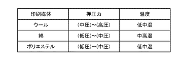
ステップS2は、入力された印刷条件に基づいて印刷媒体95を圧縮する際の条件を求める圧縮条件決定工程である。図7に示す媒体押圧テーブルは、印刷媒体95の種類と、印刷媒体95に加える押圧力の範囲と、印刷媒体95に加えることが可能な温度とを示している。押圧力の範囲は、押圧後の印刷媒体95の風合いを考慮して予め決められている。温度は、各種の印刷媒体95の耐熱性により決められている。
Step S2 is a compression condition determination step for determining the conditions for compressing the
ステップS2では、制御部1がステップS1で入力された印刷条件に応じて媒体プレス部70(媒体押圧手段79)の押圧力、及び媒体加熱手段75の温度を変更可能に制御するための押圧力、及び温度を決定する。制御部1は、選択された印刷媒体の種類に応じて、記憶部5に格納されている印刷媒体95に加える押圧力と印刷媒体95の高さとの関係を示すデータ(図4参照)、媒体押圧テーブルを参照する。例えば、印刷媒体95としてウールが選択された場合、媒体押圧テーブルより、制御部1は、媒体押圧手段79の押圧力を「中圧」から「高圧」の範囲で変更可能になり、媒体加熱手段75の温度を「低中温」または媒体加熱手段の駆動を「OFF」に変更可能になる。
In step S2, the pressing force for controlling the pressing force of the medium pressing unit 70 (medium pressing means 79) and the temperature of the medium heating means 75 can be changed by the
例えば、ステップS1にて、印刷媒体95がウールに、ギャップWGが3mmに、媒体加熱の有無が「媒体加熱:あり」に、設定された場合、制御部1は、媒体加熱手段75の設定温度を「低中温」に決定する。そして、図4の加熱ありの破線を参照して、媒体押圧手段79の押圧力を、ギャップWGから所定の値を減じた高さに印刷媒体95が圧縮される「中圧」に決定する。
また、例えば、ステップS1にて、印刷媒体95がウールに、ギャップWGが3mmに、媒体加熱の有無が「媒体加熱:なし」に、設定された場合、制御部1は、媒体加熱手段75の駆動を「OFF」に決定する。そして、図4の加熱なしの実線を参照して、媒体押圧手段79の押圧力を、ギャップWGから所定の値を減じた高さに印刷媒体95が圧縮される「高圧」に決定する。
For example, in step S1, when the
Further, for example, when the
ステップS3は、印刷条件が適正かを判断する判断工程である。入力条件が適正な場合(ステップS3:Yes)は、ステップS4に進む。入力条件が不適切な場合(ステップS3:No)は、ステップS7に進む。例えば、ステップS1にて、印刷媒体95がウールに、ギャップWGが2.5mmに、媒体加熱の有無が「媒体加熱:なし」に、設定された場合、印刷媒体95をギャップWGから所定の値を減じた高さに圧縮させるのに必要な押圧力は、ウールの押圧力の上限である「高圧」以上となる(図4の実線を参照)。したがって、制御部1は、入力された印刷条件が不適切であると判断する。なお、ここでは説明の便宜上、ステップS2とステップS3との2ステップに分けて説明したが、この2ステップは略同時に進行する。
Step S3 is a determination step for determining whether the printing conditions are appropriate. If the input conditions are appropriate (step S3: Yes), the process proceeds to step S4. If the input condition is inappropriate (step S3: No), the process proceeds to step S7. For example, in step S1, when the
ステップS4は、媒体押圧手段の駆動工程である。制御部1は、媒体押圧手段79をステップS2で決定された押圧力に制御し駆動する。
Step S4 is a step of driving the medium pressing means. The
ステップS5は、媒体加熱手段の駆動工程である。制御部1は、媒体加熱手段75をステップS2で決定された設定温度に制御し駆動する。なお、媒体加熱の有無が「媒体加熱:なし」に設定された場合、制御部1は、媒体加熱手段75の駆動を「OFF」にする。なお、ステップS4とステップS5とは、同時に行われてもよいし、逆の順序で行われてもよい。
Step S5 is a driving step of the medium heating means. The
ステップS6は、印刷媒体を搬送する媒体搬送工程である。制御部1が、媒体搬送部20を駆動し、媒体プレス部70において印刷媒体95が搬送方向(+X軸方向)に搬送されることにより、印刷媒体95の毛羽層95bが媒体プレス部70で毛羽層95cに圧縮され、印刷媒体95の高さがギャップWGよりも低くなる。圧縮された印刷媒体95は、印刷部40に搬送され、印刷媒体95上に画像などが印刷される。これにより、吐出ヘッド42と印刷媒体95の毛羽層95cとの接触機会が低減され、液滴が吐出されないノズル抜けや吐出された液滴の着弾ずれなどの不具合が生じ難くなる。また、毛羽層95bが高い印刷媒体95であっても、ギャップWG(吐出ヘッド42)を圧縮前の印刷媒体95より低く設定することが可能になるので、印刷媒体95上に鮮明な画像を印刷させることができる。これにより、布帛などの印刷媒体95上に印刷品質の優れた画像が形成される。なお、ステップS4からステップS6の工程は、印刷媒体95を圧縮する媒体圧縮工程に相当する。
Step S6 is a medium transfer step of conveying the print medium. The
ステップS7は、報知部92に報知する報知工程である。制御部1は、例えば、入力された印刷条件にて、印刷媒体95の高さをギャップWGよりも低く圧縮させることができない場合に警報を報知部92に報知する。例えば、ステップS3で説明した事例の場合には、制御部1は、不適切な入力と判断した入力項目「ギャップWG」、「媒体加熱:なし」に対応した警報を報知する。これにより、画像品質の劣化した印刷が行われることが、事前に防止される。
Step S7 is a notification step of notifying the
なお、本実施形態では、媒体押圧手段の押圧力、及び媒体加熱手段の温度を変更可能に制御する構成(方法)を示したが、これに限定するものではない。媒体押圧手段の押圧力、及び媒体加熱手段の温度のうちの少なくとも一方を変更可能に制御する構成(方法)であってもよい。 In this embodiment, a configuration (method) for controlling the pressing force of the medium pressing means and the temperature of the medium heating means in a changeable manner is shown, but the present invention is not limited to this. The structure (method) may be such that at least one of the pressing force of the medium pressing means and the temperature of the medium heating means can be changed and controlled.
以上述べたように、本実施形態に係る印刷装置100によれば、以下の効果を得ることができる。
印刷装置100は、印刷媒体95の毛羽層95bの毛羽を圧縮させる媒体プレス部70を備えている。制御部1は、入力装置6に入力された、無端ベルト48と吐出ヘッド42との間の距離(ギャップWG)、印刷媒体95の種類、及び媒体加熱の有無などの印刷条件に応じて、媒体プレス部70の媒体押圧手段79及び媒体加熱手段75を制御する。媒体プレス部70において印刷媒体95が搬送方向に搬送されることにより、毛羽層95bが毛羽層95cに圧縮され、印刷媒体95の高さがギャップWGより低くなる。これにより、吐出ヘッド42と印刷媒体95の毛羽層95cとの接触機会が低減され、液滴が吐出されないノズル抜けや吐出された液滴の着弾ずれなどの不具合が生じ難くなる。また、毛羽層95bが高い印刷媒体95であっても、ギャップWG(吐出ヘッド42)を圧縮前の印刷媒体95より低く設定することが可能になるので、印刷媒体95上に鮮明な画像を印刷させることができる。これにより、布帛などの印刷媒体95上に印刷品質の優れた画像が形成される。したがって、印刷品質を向上させた印刷装置100を提供することができる。
As described above, according to the
The
印刷装置100は、入力された印刷条件に応じて警報を報知する報知部92を備えている。制御部1は、例えば、入力された印刷条件にて、印刷媒体95の高さをギャップWGよりも低く圧縮させることができない場合に警報を報知部92に報知するので、画像品質の劣化した印刷が行われることが、事前に防止される。
The
印刷装置100における印刷媒体95の圧縮方法は、入力装置6に入力された印刷条件に応じて、印刷媒体95を圧縮する際の条件を求める圧縮条件決定工程と、印刷媒体95を圧縮する媒体圧縮工程と、を含んでいる。圧縮条件決定工程において、制御部1は、記憶部5に格納されている媒体押圧テーブルを参照し、入力装置6に入力された、無端ベルト48と吐出ヘッド42との間の距離(ギャップWG)、印刷媒体95の種類、及び媒体加熱の有無などの印刷条件に応じて、媒体プレス部70において印刷媒体95に加える押圧力、及び温度を決定する。媒体圧縮工程において、制御部1は、圧縮条件決定工程で決定した押圧力、及び温度に基づいて媒体プレス部70の媒体押圧手段79及び媒体加熱手段75を制御する。媒体プレス部70において印刷媒体95が搬送方向に搬送されることにより、毛羽層95bが毛羽層95cに圧縮され、印刷媒体95の高さがギャップWGより低くなる。これにより、吐出ヘッド42と印刷媒体95の毛羽層95cとの接触機会が低減され、液滴が吐出されないノズル抜けや吐出された液滴の着弾ずれなどの不具合が生じ難くなる。また、毛羽層95bが高い印刷媒体95であっても、ギャップWG(吐出ヘッド42)を圧縮前の印刷媒体95より低く設定することが可能になるので、印刷媒体95上に鮮明な画像を印刷させることができる。これにより、布帛などの印刷媒体95上に印刷品質の優れた画像が形成される。したがって、印刷品質を向上させることが可能な印刷媒体95の圧縮方法を提供することができる。
The method of compressing the
なお、本発明は上述した実施形態に限定されず、上述した実施形態に種々の変更や改良などを加えることが可能である。変形例を以下に述べる。 The present invention is not limited to the above-described embodiment, and various changes and improvements can be added to the above-described embodiment. A modified example will be described below.
(変形例1)
図8は、変形例1に係る媒体プレス部の構成を示す断面図である。
上記実施形態では、図2に示したように、回転軸71a,72aには、媒体加熱手段75が設けられているものと説明したが、この構成に限定するものではない。
以下、変形例1に係る印刷装置200について説明する。なお、実施形態と同一の構成部位については、同一の番号を附し、重複する説明は省略する。
(Modification example 1)
FIG. 8 is a cross-sectional view showing the configuration of the medium press portion according to the first modification.
In the above embodiment, as shown in FIG. 2, it has been described that the
Hereinafter, the
媒体プレス部170には、印刷媒体95を加熱する媒体加熱手段175a,175bが備えられている。図8に示すように、印刷媒体95の搬送方向において、印刷媒体95を押圧する第1、第2回転ローラー71、72の上流側には、印刷媒体95を上下方向(±Z軸方向)から加熱する一対の媒体加熱手段175a,175bが設けられている。媒体加熱手段175a,175bは、印刷媒体95の幅よりも長い板状の直方体をなし、Y軸方向(幅方向)において、印刷媒体95の外側に立設しているフレーム部90cと図示しないフレーム部との間に支持されている。
The
媒体加熱手段175a,175bとしては、例えば、IRヒーターなどの加熱部材を採用することができる。媒体加熱手段175a,175bを制御部1によって制御することにより、印刷媒体95を所定の温度で加熱することができるようになっている。媒体加熱手段175a,175bで加熱された印刷媒体95は、媒体搬送部20の駆動により下流側に搬送され第1、第2回転ローラー71,72で押圧される。印刷媒体95を媒体加熱手段175a,175bで加熱することで、印刷媒体95の毛羽層95bの圧縮効果を向上させることができる。なお、本変形例では、媒体加熱手段175a,175bが印刷媒体95の上下方向の両側に設けられた構成を示したが、これに限定するものではない。媒体加熱手段が印刷媒体95の上側と下側とのうちのいずれか一方側に設けられた構成であってもよい。
As the medium heating means 175a and 175b, for example, a heating member such as an IR heater can be adopted. By controlling the medium heating means 175a and 175b by the
(変形例2)
図9は、変形例2に係る媒体プレス部の構成を示す断面図である。
上記実施形態では、図2に示したように、媒体プレス部70は、印刷媒体95を押圧する第1、第2回転ローラー71,72を備えているものと説明したが、この構成に限定するものではない。
以下、変形例2に係る印刷装置300について説明する。なお、実施形態と同一の構成部位については、同一の番号を附し、重複する説明は省略する。
(Modification 2)
FIG. 9 is a cross-sectional view showing the configuration of the medium press portion according to the modified example 2.
In the above embodiment, as shown in FIG. 2, it has been described that the
Hereinafter, the
図9に示すように、媒体プレス部270は、第1回転ローラー71の押圧を受けとめる押圧支持部272を備えている。押圧支持部272は、印刷媒体95の幅よりも長い板状の直方体をなし、Y軸方向(幅方向)において、印刷媒体95の外側に立設しているフレーム部90a,90bとの間に支持されている。押圧支持部272は、印刷媒体95の基布95aの下面(−Z軸側の面)に沿って設けられ、媒体加熱手段75を備えている。
As shown in FIG. 9, the
媒体押圧手段79は、押圧支持部272に対して第1回転ローラー71を押圧させる。印刷媒体95が搬送方向(+X軸方向)に搬送されると、押圧支持部272と第1回転ローラー71との間で印刷媒体95が押圧される。これにより、印刷媒体95の毛羽層95bを圧縮させ、印刷媒体95の高さを低くすることができる。なお、本変形例では、媒体加熱手段75が第1回転ローラー71及び押圧支持部272に設けられた構成を示したが、これに限定するものではない。媒体加熱手段75が、第1回転ローラー71と、押圧支持部272とのうちのすくなくとも一方に設けられた構成であってもよい。
The medium pressing means 79 presses the first
(変形例3)
図10は、変形例3に係る媒体プレス部の構成を示す断面図である。
上記実施形態では、図2に示したように、媒体プレス部70は、印刷媒体95を押圧する第1、第2回転ローラー71,72を備えているものと説明したが、この構成に限定するものではない。
以下、変形例3に係る印刷装置400について説明する。なお、実施形態と同一の構成部位については、同一の番号を附し、重複する説明は省略する。
(Modification 3)
FIG. 10 is a cross-sectional view showing the configuration of the medium press portion according to the modified example 3.
In the above embodiment, as shown in FIG. 2, it has been described that the
Hereinafter, the
図10に示すように、媒体プレス部370は、印刷媒体95の上側(+Z軸側)に位置する第1プレス部371と、印刷媒体95の下側(−Z軸側)に位置する第2プレス部372などを有している。第1、第2プレス部371,372は、印刷媒体95の幅よりも長い板状の直方体をなし、Y軸方向(幅方向)において、印刷媒体95の外側に立設しているフレーム部90a,90bとの間に支持されている。
As shown in FIG. 10, the
フレーム部90a,90bの少なくとも一方には、第1プレス部371と第2プレス部372とを互い向き合う方向に押圧する媒体押圧手段379が備えられている。媒体押圧手段379としては、例えば、サーボモーターを動力源として、その回転力をボールねじで垂直方向(Z軸方向)の押圧力に変換する機構などを採用することができる。媒体押圧手段379は制御部1によって制御される。
At least one of the
媒体押圧手段379の駆動は、媒体搬送部20の駆動と同期するように制御される。具体的には、制御部1は、媒体搬送部20を駆動させて印刷媒体95を所定の搬送量で搬送方向に搬送する。そして、制御部1は、キャリッジ移動部41と吐出ヘッド42とを制御して停止している印刷媒体95上にインクを吐出させながら吐出ヘッド42を搬送方向と交差する方向に移動する。これを交互に繰り返すことで印刷媒体95に画像などを印刷させている。すなわち、制御部1は、印刷媒体95の搬送と停止とを繰り返している。
The drive of the medium
制御部1は、印刷媒体95の搬送を停止させている時に、媒体押圧手段379を駆動することにより、第1プレス部371と第2プレス部372との間に位置している印刷媒体95を所定の圧力で押圧することができる。制御部1が、媒体搬送部20の駆動と、媒体押圧手段379の駆動とを繰り返すことで、印刷媒体95の毛羽層95bが順次圧縮され、毛羽の高さが低い毛羽層95cが形成される。これにより、高さが低くなった印刷媒体95を印刷部40に供給することができる。
The
媒体プレス部370には、印刷媒体95を加熱する媒体加熱手段75が備えられている。第1、第2プレス部371,372には、実施形態で述べた加熱部材が設けられており、第1プレス部371及び第2プレス部372を所定の温度に加熱可能に構成されている。媒体押圧手段379と媒体加熱手段75とを駆動し、印刷媒体95を加熱しながら押圧することで、印刷媒体95の毛羽層95bの圧縮効果を向上させることができる。なお、本変形例では、媒体加熱手段75が第1プレス部371及び第2プレス部372に設けられた構成を示したが、これに限定するものではない。媒体加熱手段が第1プレス部371と第2プレス部372とのうちのいずれか一方に設けられた構成であってもよい。
The
1…制御部、2…インターフェイス部、3…CPU、4…制御回路、5…記憶部、6…入力装置、10…媒体供給部、20…媒体搬送部、30…媒体回収部、40…印刷部、41…キャリッジ移動部、42…吐出ヘッド、43…キャリッジ、48…無端ベルト、50…洗浄ユニット、60…媒体密着部、70,170,270,370…媒体プレス部、71…第1回転ローラー、71a…回転軸、72…第2回転ローラー、72a…回転軸、75,175a,175b…媒体加熱手段、78…回転駆動モーター、79,379…媒体押圧手段、90…フレーム部、92…報知部、95…印刷媒体、95a…基布、95b,95c…毛羽層、100,200,300,400…印刷装置、272…押圧支持部、371…第1プレス部、372…第2プレス部。 1 ... Control unit, 2 ... Interface unit, 3 ... CPU, 4 ... Control circuit, 5 ... Storage unit, 6 ... Input device, 10 ... Media supply unit, 20 ... Media transfer unit, 30 ... Media recovery unit, 40 ... Printing Part, 41 ... Carriage moving part, 42 ... Discharge head, 43 ... Carriage, 48 ... Endless belt, 50 ... Cleaning unit, 60 ... Media contact part, 70, 170, 270, 370 ... Media press part, 71 ... First rotation Roller, 71a ... Rotating shaft, 72 ... Second rotating roller, 72a ... Rotating shaft, 75,175a, 175b ... Medium heating means, 78 ... Rotary driving motor, 79,379 ... Medium pressing means, 90 ... Frame part, 92 ... Notification unit, 95 ... print medium, 95a ... base cloth, 95b, 95c ... fluff layer, 100, 200, 300, 400 ... printing device, 272 ... pressing support unit, 371 ... first press unit, 372 ... second press unit ..
Claims (5)
前記印刷媒体を搬送方向に搬送させる搬送手段と、
前記搬送方向において前記吐出ヘッドより上流側に設けられ前記印刷媒体を圧縮させる媒体押圧手段を有する媒体プレス部と、
前記媒体プレス部を制御する制御部と、
前記印刷媒体の種類と、前記無端ベルトと前記吐出ヘッドとの距離と、を含む印刷条件が入力される入力手段と、
記憶部と、
を備え、
前記記憶部には、
前記印刷媒体に加える押圧力と、前記印刷媒体に前記押圧力が加えられた時の前記印刷媒体の厚さとの関係を示すデータと、
前記印刷媒体の種類に対応した前記印刷媒体に加える押圧力の範囲を示す媒体押圧テーブルと、
が記憶されており、
前記制御部は、入力された前記印刷条件と前記データと前記媒体押圧テーブルとに基づいて、前記媒体プレス部が前記印刷媒体の厚さを前記無端ベルトと前記吐出ヘッドとの距離よりも所定の値を減じた厚さに圧縮させるのに必要な押圧力を決定し、前記媒体プレス部を決定された前記押圧力に制御し駆動すること、を特徴とする印刷装置。 A discharge head that discharges liquid to a printing medium placed on an endless belt,
A transport means for transporting the print medium in the transport direction, and
A medium press unit provided on the upstream side of the discharge head in the transport direction and having a medium pressing means for compressing the print medium.
A control unit that controls the medium press unit and
The type of the print medium, input means for printing conditions are inputted; and a distance between the endless belt and the ejection head,
Memory and
With
In the storage unit
Data showing the relationship between the pressing force applied to the printing medium and the thickness of the printing medium when the pressing force is applied to the printing medium.
A medium pressing table showing the range of pressing force applied to the printing medium corresponding to the type of the printing medium, and a medium pressing table.
Is remembered,
Based on the input printing conditions, the data, and the medium pressing table, the control unit determines the thickness of the printing medium by the medium pressing unit rather than the distance between the endless belt and the ejection head. A printing apparatus comprising: determining a pressing force required to compress a value to a reduced thickness, and controlling and driving the medium pressing unit to the determined pressing force.
前記媒体密着部は、
前記印刷媒体を鉛直方向の下方側に押圧する押圧ローラーと、
前記無端ベルトを挟んで前記押圧ローラーと対向する前記無端ベルトの内周面側に設けられたローラー支持部と、
前記押圧ローラーを前記鉛直方向の下方側に押圧しながら、前記搬送方向及び前記搬送方向と逆方向に前記押圧ローラーを移動させる押圧ローラー駆動部と、
を有し、
前記印刷媒体は、前記押圧ローラーと前記ローラー支持部との間で前記無端ベルトに押し当てられることで、前記無端ベルトの表面に設けられている粘着層に密着されることを特徴とする請求項1に記載の印刷装置。 It is provided with a medium contact portion that is arranged downstream of the medium press portion and upstream of the discharge head in the transport direction and adheres the print medium to the endless belt.
The medium contact portion is
A pressing roller that presses the print medium downward in the vertical direction,
A roller support portion provided on the inner peripheral surface side of the endless belt facing the pressing roller across the endless belt, and
A pressing roller driving unit that moves the pressing roller in the conveying direction and in the direction opposite to the conveying direction while pressing the pressing roller downward in the vertical direction.
Have,
The claim is characterized in that the print medium is pressed against the endless belt between the pressing roller and the roller support portion, so that the print medium is brought into close contact with an adhesive layer provided on the surface of the endless belt. The printing apparatus according to 1.
前記印刷条件は、前記印刷媒体の加熱の有無に関する情報を含み、
前記媒体押圧テーブルは、前記印刷媒体の種類に対応した前記印刷媒体に加える押圧力の範囲及び前記印刷媒体に加えることが可能な温度を示しており、
前記制御部は、前記印刷条件に応じて前記媒体加熱手段を制御すること、を特徴とする請求項1または請求項2に記載の印刷装置。 The medium press unit has a medium heating means for heating the print medium.
The printing conditions include information regarding the presence or absence of heating of the printing medium.
The medium pressing table shows the range of pressing force applied to the printing medium corresponding to the type of the printing medium and the temperature that can be applied to the printing medium.
The printing apparatus according to claim 1 or 2, wherein the control unit controls the medium heating means according to the printing conditions.
入力された前記印刷条件と前記データと前記媒体押圧テーブルとに基づいて、前記媒体プレス部が前記印刷媒体の厚さを前記無端ベルトと前記吐出ヘッドとの距離よりも所定の値を減じた厚さに圧縮させるのに必要な押圧力を決定する圧縮条件決定工程と、
前記圧縮条件決定工程で決定した前記押圧力で前記印刷媒体を圧縮する媒体圧縮工程と、
を含んでいること、を特徴とする印刷媒体の圧縮方法。 A discharge head that discharges liquid to a print medium mounted on an endless belt, a transport means that transports the print medium in a transport direction, and a transport means that is provided upstream of the discharge head in the transport direction to compress the print medium. a medium pressing portion having a medium pressing means, input means for printing conditions are input, and a control unit for controlling the medium press section, the type of the print medium, the distance between the endless belt and the ejection head, A storage unit is provided with an input means for inputting printing conditions including the above, and the storage unit includes a pressing force applied to the printing medium and the printing medium when the pressing force is applied to the printing medium. A method for compressing a printing medium in a printing apparatus in which data indicating a relationship with the thickness of the printing medium and a medium pressing table indicating a range of pressing force applied to the printing medium corresponding to the type of the printing medium are stored.
Based on the input printing conditions, the data, and the medium pressing table, the medium pressing unit reduces the thickness of the printing medium by a predetermined value from the distance between the endless belt and the ejection head. A compression condition determination process that determines the pressing force required for compression, and
A medium compression step of compressing the print medium with the pressing force determined in the compression condition determination step,
A method of compressing a print medium, characterized in that it contains.
Priority Applications (4)
| Application Number | Priority Date | Filing Date | Title |
|---|---|---|---|
| JP2016009510A JP6776541B2 (en) | 2016-01-21 | 2016-01-21 | Printing device and compression method of printing medium |
| US15/407,563 US9962965B2 (en) | 2016-01-21 | 2017-01-17 | Printing apparatus and method for compressing printing medium |
| CN201710032824.0A CN107042706B (en) | 2016-01-21 | 2017-01-17 | Printing device and method for compressing printing medium |
| EP17152388.9A EP3205508B1 (en) | 2016-01-21 | 2017-01-20 | Printing apparatus and method for compressing printing medium |
Applications Claiming Priority (1)
| Application Number | Priority Date | Filing Date | Title |
|---|---|---|---|
| JP2016009510A JP6776541B2 (en) | 2016-01-21 | 2016-01-21 | Printing device and compression method of printing medium |
Publications (2)
| Publication Number | Publication Date |
|---|---|
| JP2017128828A JP2017128828A (en) | 2017-07-27 |
| JP6776541B2 true JP6776541B2 (en) | 2020-10-28 |
Family
ID=57860755
Family Applications (1)
| Application Number | Title | Priority Date | Filing Date |
|---|---|---|---|
| JP2016009510A Active JP6776541B2 (en) | 2016-01-21 | 2016-01-21 | Printing device and compression method of printing medium |
Country Status (4)
| Country | Link |
|---|---|
| US (1) | US9962965B2 (en) |
| EP (1) | EP3205508B1 (en) |
| JP (1) | JP6776541B2 (en) |
| CN (1) | CN107042706B (en) |
Families Citing this family (6)
| Publication number | Priority date | Publication date | Assignee | Title |
|---|---|---|---|---|
| JP2019119146A (en) * | 2018-01-09 | 2019-07-22 | セイコーエプソン株式会社 | Printing device and method for heating medium |
| JP7135538B2 (en) * | 2018-07-27 | 2022-09-13 | コニカミノルタ株式会社 | Cloth conveying device and inkjet recording device |
| JP7346882B2 (en) * | 2019-04-10 | 2023-09-20 | セイコーエプソン株式会社 | printing device |
| CN111873631B (en) * | 2020-07-01 | 2021-12-03 | 保定美雅纺织有限公司 | Printed cloth printing and dyeing machine |
| CN112248660B (en) * | 2020-10-15 | 2021-06-04 | 江苏汉印机电科技股份有限公司 | Intelligent textile fabric jet printing machine |
| CN114633550A (en) * | 2022-03-24 | 2022-06-17 | 郑萍娟 | Spray printing method of high-performance blended fabric |
Family Cites Families (14)
| Publication number | Priority date | Publication date | Assignee | Title |
|---|---|---|---|---|
| JP2826773B2 (en) * | 1991-02-01 | 1998-11-18 | キヤノン株式会社 | Ink jet recording device |
| US7073902B2 (en) * | 2001-03-30 | 2006-07-11 | L&P Property Management Company | Method and apparatus for ink jet printing |
| JP2004167757A (en) * | 2002-11-18 | 2004-06-17 | Fuji Photo Film Co Ltd | Surface treating device and image forming apparatus |
| US7316474B2 (en) * | 2002-11-18 | 2008-01-08 | Fuji Photo Film Co., Ltd. | Surface treatment apparatus and image recording apparatus |
| JP5051496B2 (en) | 2006-02-21 | 2012-10-17 | Tbカワシマ株式会社 | Woolen fabric and printing method |
| JP5857486B2 (en) * | 2011-07-14 | 2016-02-10 | セイコーエプソン株式会社 | Inkjet printing device |
| JP2013052654A (en) * | 2011-09-06 | 2013-03-21 | Seiko Epson Corp | Inkjet recording method and recording matter |
| US8833892B2 (en) * | 2012-06-12 | 2014-09-16 | Seiko Epson Corporation | Printing apparatus and printing method |
| US8899583B2 (en) * | 2013-03-15 | 2014-12-02 | Xerox Corporation | Tracking in belt on belt architecture through self-alignment |
| JP2014189377A (en) * | 2013-03-27 | 2014-10-06 | Seiko Epson Corp | Recording apparatus and recording method |
| JP2015089636A (en) * | 2013-11-06 | 2015-05-11 | セイコーエプソン株式会社 | Printer and printing method |
| JP6304485B2 (en) * | 2014-02-25 | 2018-04-04 | セイコーエプソン株式会社 | Liquid ejection apparatus and medium flattening method |
| JP6222464B2 (en) | 2014-02-25 | 2017-11-01 | セイコーエプソン株式会社 | Liquid ejection apparatus and medium pretreatment method |
| JP6269232B2 (en) * | 2014-03-25 | 2018-01-31 | セイコーエプソン株式会社 | Textile printing equipment |
-
2016
- 2016-01-21 JP JP2016009510A patent/JP6776541B2/en active Active
-
2017
- 2017-01-17 CN CN201710032824.0A patent/CN107042706B/en active Active
- 2017-01-17 US US15/407,563 patent/US9962965B2/en active Active
- 2017-01-20 EP EP17152388.9A patent/EP3205508B1/en active Active
Also Published As
| Publication number | Publication date |
|---|---|
| US20170210150A1 (en) | 2017-07-27 |
| EP3205508A1 (en) | 2017-08-16 |
| EP3205508B1 (en) | 2021-11-03 |
| US9962965B2 (en) | 2018-05-08 |
| CN107042706B (en) | 2020-12-08 |
| JP2017128828A (en) | 2017-07-27 |
| CN107042706A (en) | 2017-08-15 |
Similar Documents
| Publication | Publication Date | Title |
|---|---|---|
| JP6776541B2 (en) | Printing device and compression method of printing medium | |
| JP6988164B2 (en) | Printing equipment | |
| JP6686447B2 (en) | Printer | |
| JP6988096B2 (en) | Head unit and liquid discharge device | |
| JP6720576B2 (en) | Printer | |
| JP6919327B2 (en) | Printing device and belt movement amount difference detection method | |
| JP6390831B2 (en) | Liquid discharge apparatus and liquid discharge manufacturing method | |
| JP6135069B2 (en) | Droplet ejector | |
| JP6693091B2 (en) | Printer | |
| CN102555542B (en) | Image recording apparatus and image recording method | |
| JP6701768B2 (en) | Printing device and printing method | |
| JP6701808B2 (en) | Printer | |
| CN107042707B (en) | Liquid ejecting apparatus | |
| JP2014000702A (en) | Liquid jet apparatus | |
| JP2021115817A (en) | Transport device and recording device | |
| JP2017132176A (en) | Printer, and printing method | |
| JP6686722B2 (en) | Printing device and ejection timing adjusting method | |
| JP7238332B2 (en) | Inkjet recording apparatus and inkjet recording method | |
| JP2021102293A (en) | Printer | |
| JP2016210582A (en) | Recording device | |
| JP2024024203A (en) | liquid discharge device | |
| JP2021102507A (en) | Printer | |
| JP2020050476A (en) | Medium conveyance device and liquid discharge device | |
| JP2016204090A (en) | Recording device |
Legal Events
| Date | Code | Title | Description |
|---|---|---|---|
| RD05 | Notification of revocation of power of attorney |
Free format text: JAPANESE INTERMEDIATE CODE: A7425 Effective date: 20180906 |
|
| A621 | Written request for application examination |
Free format text: JAPANESE INTERMEDIATE CODE: A621 Effective date: 20181016 |
|
| RD03 | Notification of appointment of power of attorney |
Free format text: JAPANESE INTERMEDIATE CODE: A7423 Effective date: 20181119 |
|
| A977 | Report on retrieval |
Free format text: JAPANESE INTERMEDIATE CODE: A971007 Effective date: 20190813 |
|
| A131 | Notification of reasons for refusal |
Free format text: JAPANESE INTERMEDIATE CODE: A131 Effective date: 20190820 |
|
| A521 | Written amendment |
Free format text: JAPANESE INTERMEDIATE CODE: A523 Effective date: 20191008 |
|
| A131 | Notification of reasons for refusal |
Free format text: JAPANESE INTERMEDIATE CODE: A131 Effective date: 20200310 |
|
| A521 | Written amendment |
Free format text: JAPANESE INTERMEDIATE CODE: A523 Effective date: 20200422 |
|
| RD07 | Notification of extinguishment of power of attorney |
Free format text: JAPANESE INTERMEDIATE CODE: A7427 Effective date: 20200803 |
|
| TRDD | Decision of grant or rejection written | ||
| A01 | Written decision to grant a patent or to grant a registration (utility model) |
Free format text: JAPANESE INTERMEDIATE CODE: A01 Effective date: 20200908 |
|
| A61 | First payment of annual fees (during grant procedure) |
Free format text: JAPANESE INTERMEDIATE CODE: A61 Effective date: 20200921 |
|
| R150 | Certificate of patent or registration of utility model |
Ref document number: 6776541 Country of ref document: JP Free format text: JAPANESE INTERMEDIATE CODE: R150 |