JP6776154B2 - Radial turbine, exhaust parts of radial turbine - Google Patents
Radial turbine, exhaust parts of radial turbine Download PDFInfo
- Publication number
- JP6776154B2 JP6776154B2 JP2017035465A JP2017035465A JP6776154B2 JP 6776154 B2 JP6776154 B2 JP 6776154B2 JP 2017035465 A JP2017035465 A JP 2017035465A JP 2017035465 A JP2017035465 A JP 2017035465A JP 6776154 B2 JP6776154 B2 JP 6776154B2
- Authority
- JP
- Japan
- Prior art keywords
- flow path
- downstream side
- working fluid
- rotor
- path portion
- Prior art date
- Legal status (The legal status is an assumption and is not a legal conclusion. Google has not performed a legal analysis and makes no representation as to the accuracy of the status listed.)
- Active
Links
Images


Classifications
-
- F—MECHANICAL ENGINEERING; LIGHTING; HEATING; WEAPONS; BLASTING
- F01—MACHINES OR ENGINES IN GENERAL; ENGINE PLANTS IN GENERAL; STEAM ENGINES
- F01D—NON-POSITIVE DISPLACEMENT MACHINES OR ENGINES, e.g. STEAM TURBINES
- F01D25/00—Component parts, details, or accessories, not provided for in, or of interest apart from, other groups
- F01D25/24—Casings; Casing parts, e.g. diaphragms, casing fastenings
-
- F—MECHANICAL ENGINEERING; LIGHTING; HEATING; WEAPONS; BLASTING
- F01—MACHINES OR ENGINES IN GENERAL; ENGINE PLANTS IN GENERAL; STEAM ENGINES
- F01D—NON-POSITIVE DISPLACEMENT MACHINES OR ENGINES, e.g. STEAM TURBINES
- F01D25/00—Component parts, details, or accessories, not provided for in, or of interest apart from, other groups
- F01D25/30—Exhaust heads, chambers, or the like
-
- F—MECHANICAL ENGINEERING; LIGHTING; HEATING; WEAPONS; BLASTING
- F02—COMBUSTION ENGINES; HOT-GAS OR COMBUSTION-PRODUCT ENGINE PLANTS
- F02B—INTERNAL-COMBUSTION PISTON ENGINES; COMBUSTION ENGINES IN GENERAL
- F02B39/00—Component parts, details, or accessories relating to, driven charging or scavenging pumps, not provided for in groups F02B33/00 - F02B37/00
-
- F—MECHANICAL ENGINEERING; LIGHTING; HEATING; WEAPONS; BLASTING
- F02—COMBUSTION ENGINES; HOT-GAS OR COMBUSTION-PRODUCT ENGINE PLANTS
- F02C—GAS-TURBINE PLANTS; AIR INTAKES FOR JET-PROPULSION PLANTS; CONTROLLING FUEL SUPPLY IN AIR-BREATHING JET-PROPULSION PLANTS
- F02C3/00—Gas-turbine plants characterised by the use of combustion products as the working fluid
- F02C3/04—Gas-turbine plants characterised by the use of combustion products as the working fluid having a turbine driving a compressor
- F02C3/045—Gas-turbine plants characterised by the use of combustion products as the working fluid having a turbine driving a compressor having compressor and turbine passages in a single rotor-module
- F02C3/05—Gas-turbine plants characterised by the use of combustion products as the working fluid having a turbine driving a compressor having compressor and turbine passages in a single rotor-module the compressor and the turbine being of the radial flow type
-
- F—MECHANICAL ENGINEERING; LIGHTING; HEATING; WEAPONS; BLASTING
- F02—COMBUSTION ENGINES; HOT-GAS OR COMBUSTION-PRODUCT ENGINE PLANTS
- F02C—GAS-TURBINE PLANTS; AIR INTAKES FOR JET-PROPULSION PLANTS; CONTROLLING FUEL SUPPLY IN AIR-BREATHING JET-PROPULSION PLANTS
- F02C7/00—Features, components parts, details or accessories, not provided for in, or of interest apart form groups F02C1/00 - F02C6/00; Air intakes for jet-propulsion plants
-
- F—MECHANICAL ENGINEERING; LIGHTING; HEATING; WEAPONS; BLASTING
- F04—POSITIVE - DISPLACEMENT MACHINES FOR LIQUIDS; PUMPS FOR LIQUIDS OR ELASTIC FLUIDS
- F04D—NON-POSITIVE-DISPLACEMENT PUMPS
- F04D29/00—Details, component parts, or accessories
- F04D29/40—Casings; Connections of working fluid
- F04D29/52—Casings; Connections of working fluid for axial pumps
- F04D29/54—Fluid-guiding means, e.g. diffusers
Description
本発明は、ラジアルタービン、ラジアルタービンの排気部材に関するものである。 The present invention relates to a radial turbine and an exhaust member of the radial turbine .
ターボチャージャに用いられるラジアルタービン(遠心タービン)または軸流タービン、高炉用の軸流ブロワ等の回転機械は、ケーシングと、ケーシング内に回転可能に設けられたロータと、ロータの外周部に設けられた翼と、を備えている。このような回転機械には、外部から送り込まれた作動流体によって、翼を有したロータが回転するものがある。また、翼を有したロータを外部から伝達される動力によって回転させることで、作動流体を送り出すものもある。 Rotating machines such as radial turbines (centrifugal turbines) or axial-flow turbines used for turbochargers and axial-flow blowers for blast furnaces are provided on a casing, a rotor rotatably provided in the casing, and an outer peripheral portion of the rotor. It has wings and wings. In some such rotating machines, a rotor having blades is rotated by a working fluid sent from the outside. In some cases, a rotor having wings is rotated by power transmitted from the outside to send out a working fluid.
ところで、このような回転機械においては、性能の観点で、翼を経た作動流体の流速を効率良く圧力に変換することが望まれる。
そこで、例えば特許文献1に開示されているように、作動流体の排気流路に、流路断面積が漸次拡大する拡径流路(ディフューザ)を備える構成が多用されている。このような拡径流路を設けることで、圧縮された作動流体の圧力を漸次低下させ、例えば大気圧中に排気することができる。
By the way, in such a rotating machine, from the viewpoint of performance, it is desired to efficiently convert the flow velocity of the working fluid through the blades into pressure.
Therefore, for example, as disclosed in Patent Document 1, a configuration is often used in which the exhaust flow path of the working fluid is provided with a diameter-expanding flow path (diffuser) in which the cross-sectional area of the flow path gradually increases. By providing such an expanded flow path, the pressure of the compressed working fluid can be gradually reduced and exhausted to, for example, atmospheric pressure.
ところで、例えば、図11に示すように、ターボチャージャに用いられるラジアルタービン1の場合、作動流体は、ケーシング2の外周側から羽根車3に沿って流れて向きを変え、羽根車3の内周側から中心軸方向に沿って排出される。この場合、羽根車3の中央部3cの下流側においては、羽根車3の内周側から中心軸方向に沿って流れ出る作動流体の一部が剥離し、剥離渦を形成する。この剥離渦を生成する領域S1は、実質的に作動流体が流れる流路として機能しない。このため、その下流側で剥離渦が生成される領域の影響を受ける拡径流路4では、圧力回復の効率が損なわれる場合がある。
By the way, for example, as shown in FIG. 11, in the case of the radial turbine 1 used in the turbocharger, the working fluid flows from the outer peripheral side of the
また、図12に示すように、軸流ブロワ5等の場合、ケーシング6と、ケーシング6内に設けられたロータ7との間を流れる作動流体が、動翼8Aや静翼8Bの下流側で剥離する場合がある。例えば、静翼8Bの下流側で、ロータ7の表面に沿って流れる作動流体に剥離が生じた場合、剥離が生じた領域S2は、実質的に作動流体が流れる流路として機能しない。このため、その下流側で剥離が生じる領域S2の影響を受ける拡径流路9では、圧力回復の効率が損なわれる場合がある。
Further, as shown in FIG. 12, in the case of the axial flow blower 5 or the like, the working fluid flowing between the
本発明は、このような事情に鑑みてなされたものであって、流路内で剥離が生じる領域を低減し、拡径流路における圧力回復の効率を高めることができるラジアルタービン、ラジアルタービンの排気部材を提供することを目的とする。 The present invention has been made in view of such circumstances, and is capable of reducing the region where peeling occurs in the flow path and increasing the efficiency of pressure recovery in the enlarged diameter flow path, and exhaust gas of the radial turbine and the radial turbine . The purpose is to provide a member.
上記課題を解決するために、本発明のラジアルタービン、ラジアルタービンの排気部材は以下の手段を採用する。
本発明に係るラジアルタービンは、中心軸回りに回転可能に設けられたロータと、前記ロータの外周部に固定された回転翼と、前記ロータおよび前記回転翼の外周側に設けられ、その内側に作動流体の流路を形成するケーシングと、前記回転翼よりも前記作動流体の流れ方向の下流側に設けられ、下流側に向かって前記作動流体の流路断面積が漸次縮小する縮小流路部と、前記縮小流路部の下流側に設けられ、下流側に向かって前記作動流体の流路断面積が漸次拡大する拡大流路部と、を備え、前記縮小流路部の前記流れ方向における長さは、前記回転翼の出口幅よりも小さくされ、前記縮小流路部による前記流路の縮径量は、前記回転翼の前記出口幅よりも小さくされていることを特徴とする。
In order to solve the above problems, the following means are adopted for the radial turbine and the exhaust member of the radial turbine of the present invention.
The radial turbine according to the present invention includes a rotor rotatably provided around the central axis, rotary blades fixed to the outer peripheral portion of the rotor, and the rotor and the outer peripheral side of the rotary blade provided inside the rotor. A casing that forms a flow path for the working fluid, and a reduced flow path portion that is provided on the downstream side of the rotary blade in the flow direction of the working fluid and the cross-sectional area of the flow path of the working fluid gradually decreases toward the downstream side. And an enlarged flow path portion provided on the downstream side of the reduced flow path portion and gradually expanding the flow path cross-sectional area of the working fluid toward the downstream side, in the flow direction of the reduced flow path portion. length, the is smaller than the outlet width of the rotor blades, diameter reduction of the flow channel by the reduced flow passage portion is characterized that you have been smaller than the outlet width of said rotating blade.
本発明に係るラジアルタービンによれば、回転翼よりも作動流体の流れ方向の下流側に縮小流路部が設けられることで、作動流体の流路が狭まる。これによって、流路が狭まった部分においては、作動流体が実質的に流れる領域に対し、回転翼の下流側で剥離が生じ得る領域が相対的に減少する。このようにして流路内で作動流体の剥離が生じる領域を低減することができる。このような縮小流路部を経た後に、拡大流路部にて作動流体の流路断面積を漸次拡大させることで、作動流体の圧力回復の効率を高めることができる。 According to the radial turbine according to the present invention, the flow path of the working fluid is narrowed by providing the reduced flow path portion on the downstream side of the rotary blade in the flow direction of the working fluid. As a result, in the portion where the flow path is narrowed, the region where the working fluid can substantially flow is relatively reduced in the region where the separation can occur on the downstream side of the rotor blade. In this way, it is possible to reduce the region where the working fluid is separated in the flow path. After passing through such a reduced flow path portion, the efficiency of pressure recovery of the working fluid can be improved by gradually expanding the flow path cross-sectional area of the working fluid in the enlarged flow path portion.
上記ラジアルタービンにおいて、前記ロータ及び前記回転翼よりも下流側に向かって延び、前記作動流体を下流側に排出する排出部をさらに備え、前記縮小流路部および前記拡大流路部は、前記排出部において前記ロータの前記流れ方向下流側の端部よりも下流側に形成されているとさらに好適である。 The radial turbine further includes a discharge portion that extends toward the downstream side of the rotor and the rotary blade and discharges the working fluid to the downstream side, and the reduced flow path portion and the expanded flow path portion are the discharge portion. It is more preferable that the rotor is formed on the downstream side of the end portion on the downstream side in the flow direction of the rotor.
このようなラジアルタービンによれば、ロータの下流側の端部では、その下流側で作動流体の剥離が生じやすい。このような構成において、ロータの下流側の端部よりも下流側に縮小流路部を設けることで、作動流体の剥離が生じる領域を、効果的に低減することができる。 According to such a radial turbine , at the downstream end of the rotor, the working fluid is likely to be separated on the downstream side. In such a configuration, by providing the reduced flow path portion on the downstream side of the end on the downstream side of the rotor, the region where the working fluid is separated can be effectively reduced.
本発明の参考例に係る回転機械において、ケーシングおよびロータは、回転翼よりも流れ方向の下流側に向かって延び、縮小流路部は、回転翼よりも下流側で、ケーシングおよびロータの少なくとも一方に形成されているとさらに好適である。 The rotary machine according to a reference example of the present invention, Quai pacing and B over data extends toward the downstream side of the direction and flow than times Utatetsubasa, reduced small flow path section, downstream of the times Utatetsubasa on the side, it is more preferable that is formed on at least one case and pacing and b over data.
このような回転機械によれば、ケーシングおよびロータが、回転翼よりも下流側に連続して延びている構成において、作動流体の剥離が生じる領域を、効果的に低減することができる。 According to such a rotary machine, the region where the working fluid is separated can be effectively reduced in the configuration in which the casing and the rotor extend continuously to the downstream side of the rotary blade.
本発明の参考例に係る回転機械において、回転翼よりも下流側に設けられ、ケーシングから内周側に向かって延びる静翼をさらに備え、縮小流路部は、流れ方向において静翼が設けられている領域に形成されているとさらに好適である。 The rotary machine according to a reference example of the present invention, provided downstream of the times Utatetsubasa, further comprising a stationary blade extending toward the inner peripheral side from Ke pacing, reduced small flow path section, Te flow Re direction odor vanes it is more preferable that is formed in the area provided.
このような回転機械によれば、回転翼の下流側に設けられた静翼の部分において、作動流体の剥離が生じる領域を低減することができる。 According to such a rotary machine, it is possible to reduce the region where the working fluid is separated in the portion of the stationary blade provided on the downstream side of the rotary blade.
本発明の参考例に係る回転機械において、回転翼よりも上流側に設けられ、ケーシングから内周側に向かって延びる静翼をさらに備え、縮小流路部は、回転翼よりも作動流体の流れ方向の下流側に設けられているとさらに好適である。 The rotary machine according to a reference example of the present invention, times Utatetsubasa provided upstream of the, further comprising a stationary blade extending toward the inner peripheral side from Ke pacing, reduced small flow path section than times Utatetsubasa it is more preferable that disposed downstream of the flow direction of the work movement fluid.
このような回転機械によれば、回転翼の下流側に設けられた部分において、作動流体の剥離が生じる領域を低減することができる。 According to such a rotary machine, it is possible to reduce the region where the working fluid is separated in the portion provided on the downstream side of the rotary blade.
本発明に係るラジアルタービンの排気部材は、中心軸回りに回転可能に設けられたロータ、前記ロータの外周部に固定された回転翼、および前記回転翼の外周側に設けられ、その内側に作動流体の流路を形成するケーシングを備えたラジアルタービンの排気部材であって、前記ロータ及び前記回転翼よりも下流側に向かって延びるよう設けられ、前記作動流体を下流側に排出する排気流路を形成する筒状の排気部材本体と、前記排気部材本体の内周面に形成され、前記作動流体の流れ方向の下流側に向かって前記作動流体の流路断面積が漸次縮小する縮小流路部と、前記排気部材本体の内周面の前記縮小流路部よりも下流側に形成され、下流側に向かって前記作動流体の流路断面積が漸次拡大する拡大流路部と、を備え、前記縮小流路部の前記流れ方向における長さは、前記回転翼の出口幅よりも小さくされ、前記縮小流路部による前記流路の縮径量は、前記回転翼の前記出口幅よりも小さくされていることを特徴とする。 The exhaust member of the radial turbine according to the present invention is provided on a rotor rotatably provided around the central axis, a rotary blade fixed to the outer peripheral portion of the rotor, and an outer peripheral side of the rotary blade, and operates inside the rotor. An exhaust member of a radial turbine provided with a casing forming a fluid flow path, which is provided so as to extend toward the downstream side of the rotor and the rotary blade, and discharges the working fluid to the downstream side. A reduced flow path formed on the inner peripheral surface of the tubular exhaust member body and the inner peripheral surface of the exhaust member body, and the flow path cross-sectional area of the working fluid gradually decreases toward the downstream side in the flow direction of the working fluid. A portion and an enlarged flow path portion formed on the downstream side of the reduced flow path portion on the inner peripheral surface of the exhaust member main body, and the flow path cross-sectional area of the working fluid gradually expands toward the downstream side. The length of the reduced flow path portion in the flow direction is made smaller than the outlet width of the rotary blade, and the diameter reduction amount of the flow path by the reduced flow path portion is larger than the outlet width of the rotary blade. It is smaller, characterized in Rukoto.
本発明に係るラジアルタービンの排気部材によれば、このような排気部材を設けることで、回転翼よりも作動流体の流れ方向の下流側に縮小流路部が設けられることになる。これにより、流路内で作動流体の剥離が生じる領域を低減することができる。 According to the exhaust member of the radial turbine according to the present invention, by providing such an exhaust member, a reduced flow path portion is provided on the downstream side of the rotary blade in the flow direction of the working fluid. As a result, it is possible to reduce the region where the working fluid is separated in the flow path.
本発明に係るラジアルタービン、ラジアルタービンの排気部材によれば、流路内で剥離が生じる領域を低減し、拡径流路における圧力回復の効率を高めることができる。 Radial turbine according to the present invention, according to the exhaust member of the radial turbine, to reduce the area where peeling occurs in the flow path, it is possible to increase the efficiency of the pressure recovery in the wide diameter flow path.
以下に、本発明に係るラジアルタービン、ラジアルタービンの排気部材の一実施形態について、図面を参照して説明する。
〔第1実施形態〕
以下、本発明の第1実施形態について、図1を用いて説明する。
図1に示すように、ターボチャージャに用いられるラジアルタービン(回転機械)10Aは、ケーシング11と、ロータ12と、回転翼13と、を備えている。
Hereinafter, the radial turbine according to the present invention, an embodiment of an exhaust member of the radial turbine will be described with reference to the drawings.
[First Embodiment]
Hereinafter, the first embodiment of the present invention will be described with reference to FIG.
As shown in FIG. 1, the radial turbine (rotary machine) 10A used in the turbocharger includes a
ケーシング11は、ラジアルタービン10Aの外殻を形成する。ケーシング11は、中空でその内部にロータ12を収容するロータハウジング11Rと、回転翼13の外周側を囲うように設けられた排気部材(排出部、排気部材本体)15Aなどを備えている。
また、ケーシング11には、内燃機関の排気ガス等の作動流体を径方向外側から取り入れる図示しない吸気口を有する吸気ケーシングや、静止翼11aが接続される。
The
Further, the
ロータ12は、ケーシング11内に、図示しない軸受を介して中心軸C回りに回転自在に支持された回転軸12sと、回転軸12sの中心軸C方向の一方の端部に設けられたディスク部14とを備えている。
The
ディスク部14は、中心軸Cを含む中央部に形成されたボア部14bと、ボア部14bの外周側に、中心軸C方向の一方側を向いて形成された偏向面14fと、を備えている。偏向面14fは、中心軸C方向の一方側から他方側に向かって外径が漸次拡大する凹状湾曲面によって形成され、径方向外側の吸気口11aから径方向内側に向かって取り入れた作動流体の流れ方向を中心軸C方向に偏向させる。
The
回転翼13は、ディスク部14の偏向面14fに、中心軸C回りの周方向に間隔を空けて複数が設けられている。
A plurality of
上記ケーシング11は、複数の回転翼13を、中心軸C方向の一方側から覆うように設けられたシュラウド部18を備えている。
The
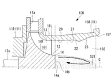
排気部材15Aは、シュラウド部18に連続して、回転翼13よりも作動流体の流れ方向の下流側、すなわち中心軸C方向一方の側に設けられている。この排気部材15Aは、筒状で、その内側に、ディスク部14の内周側(ボア部14bの外周側)から中心軸C方向一方の側(下流側)に向かって流れる作動流体の排気流路102を形成する。
The
この排気部材15Aは、その内周面15fに、縮小流路部16と、縮小流路部16の下流側に設けられた拡大流路部17と、を備えている。これら縮小流路部16および拡大流路部17は、排気部材15Aにおいてロータ12の流れ方向下流側に位置するボア部14bの端面(端部)14gよりも下流側に形成されている。
縮小流路部16は、下流側に向かってその内径が漸次縮小することで、作動流体の流路断面積が漸次縮小するよう形成されている。拡大流路部17は、縮小流路部16の下流側に連続して形成され、下流側に向かってその内径が漸次拡大することで、作動流体の流路断面積が漸次拡大するよう形成されている。
The
The reduced
上記したようなラジアルタービン10Aにおいては、吸気口11aから取り入れた作動流体は、ディスク部14の偏向面14fとシュラウド部18との間の流路101に径方向外側から内側に向かって流れ込む。この流路101に流れ込んだ作動流体が回転翼13に衝突することによって、ロータ12が中心軸回りに回転し、ロータ12の他方の端部に連結された圧縮機(図示無し)等を駆動する。作動流体は、ディスク部14の内周側(ボア部14bの外周側)から中心軸C方向一方の側(下流側)に向かって流出し、排気部材15Aの内側の排気流路102を通って外部に排出される。
In the
ここで、排気部材15A内において、ディスク部14の偏向面14fに沿って流れてきた作動流体の一部は、ディスク部14のボア部14bの端面14gの下流側で剥離して渦を生成する。これにより、ボア部14bの端面14gの下流側には、剥離渦が生成される領域S21が形成される。一方、排気部材15A内において、中心軸C方向に沿って下流側に流れる作動流体は、内周面15fに形成された縮小流路部16に沿うことで、径方向内側に偏向される。縮小流路部16を経た作動流体は、拡大流路部17において、その流路断面積が漸次拡大することで、流速が低下し、排気部材15Aの出口から、外部の例えば大気圧に開放される。
Here, in the
このようにして、縮小流路部16を備えることで、排気部材15A内の排気流路102の中央部に形成された、剥離渦が生成される領域S21は、径方向寸法が小さくなり、この領域S21の外周側で作動流体が下流側に流れる領域S22の断面積(以下、これを有効流路面積と称する)が相対的に大きくなる。
図2は、排気部材15Aの流路面積M1と、剥離渦が生成される領域S21を除いた作動流体が流れる領域S22の有効流路面積M2と、縮小流路部16を備えない場合(図11に示した構成)において剥離渦が生成される領域S21を除いた作動流体が流れる領域の有効流路面積M0と、を示すものである。この図2に示すように、縮小流路部16を備えることで、作動流体が流れる領域S22の有効流路面積M2が大きくなる。
By providing the reduced
FIG. 2 shows a case where the flow path area M1 of the
上述したようなラジアルタービン10Aおよび排気部材15Aによれば、回転翼13よりも作動流体の流れ方向の下流側に縮小流路部16が設けられることで、作動流体の流路102が狭まる。これによって、流路が狭まった部分においては、作動流体が実質的に流れる領域S22に対し、回転翼13の下流側で剥離が生じ得る領域S21が相対的に減少することとなる。このようにして流路内で作動流体の剥離が生じる領域S21を低減することができる。このような縮小流路部16を経た後に、拡大流路部17にて作動流体の流路断面積を漸次拡大させることで、作動流体の圧力回復の効率を高めることができる。
According to the
また、ディスク部14のボア部14bの下流側の端面14gの下流側に縮小流路部16を設けることで、作動流体の剥離が生じる領域S21を、効果的に低減することができる。
Further, by providing the reduced
〔第1実施形態の変形例〕
図3に示すように、ターボチャージャに用いられるラジアルタービン(回転機械)10Bの排気部材(排出部、排気部材本体)15Bは、ケーシング11のシュラウド部18に連続して、回転翼13よりも作動流体の流れ方向の下流側、すなわち中心軸C方向一方の側に設けられている。この排気部材15Bは、筒状で、その内側を、ディスク部14の内周側(ボア部14bの外周側)から下流側に向かって流れる作動流体の排気流路102を形成する。
[Modified example of the first embodiment]
As shown in FIG. 3, the exhaust member (exhaust portion, exhaust member main body) 15B of the radial turbine (rotary machine) 10B used in the turbocharger operates continuously from the
この排気部材15Bは、その内周面15fに、上流側から下流側に向かって、ストレート流路部20と、第一拡大流路部21と、縮小流路部22と、縮小流路部22の下流側に設けられた第二拡大流路部23と、を備えている。これら第一拡大流路部21、縮小流路部22および第二拡大流路部23は、排気部材15Bにおいてロータ12の流れ方向下流側に位置するボア部14bの端面14gよりも下流側に形成されている。
The
ストレート流路部20は、中心軸C方向において、一定の内径を有している。
第一拡大流路部21は、下流側に向かってその内径が漸次拡大することで、作動流体の流路断面積が漸次拡大するよう形成されている。
The straight
The inner diameter of the first expansion
縮小流路部22は、下流側に向かってその内径が漸次縮小することで、作動流体の流路断面積が漸次縮小するよう形成されている。第二拡大流路部23は、縮小流路部22の下流側に連続して形成され、下流側に向かってその内径が漸次拡大することで、作動流体の流路断面積が漸次拡大するよう形成されている。
The reduced
図4は、排気部材15Bの流路面積M11と、剥離渦が生成される領域S21を除いた作動流体が流れる領域S22の有効流路面積M12と、縮小流路部22を備えない場合(図11に示した構成)において剥離渦が生成される領域S21を除いた作動流体が流れる領域の有効流路面積M0と、を示すものである。この図4に示すように、縮小流路部22を備えることで、作動流体が流れる領域S22の有効流路面積M12が大きくなる。
FIG. 4 shows a case where the flow path area M11 of the
このような排気部材15Bにおいても、上記第1実施形態の排気部材15Aと同様、縮小流路部22が設けられることで、回転翼13の下流側で剥離が生じ得る領域S21を低減し、作動流体が実質的に流れる領域S22の有交流路断面積を増加させることができる。このような縮小流路部22を経た後に、第二拡大流路部23にて作動流体の流路断面積を漸次拡大させることで、作動流体の圧力回復の効率を高めることができる。
Similar to the
〔第1参考実施形態〕
次に、本発明の参考例に係る回転機械、回転機械の排気部材の第1参考実施形態について説明する。なお、以下の説明において、上記第1実施形態と共通する構成については同符号を付してその説明を省略する。
図5に示すように、軸流ブロワ(回転機械)10Cは、ケーシング31Cと、回転軸(ロータ)32と、動翼(回転翼)33と、静翼34と、を備えている。
[First Reference Embodiment]
Next, the first reference embodiment of the rotary machine and the exhaust member of the rotary machine according to the reference example of the present invention will be described. In the following description, the same reference numerals are given to the configurations common to the first embodiment, and the description thereof will be omitted.
As shown in FIG. 5, the axial flow blower (rotorcraft) 10C includes a
ケーシング31Cは、中心軸C方向に沿って延びる筒状をなしている。
回転軸32は、ケーシング31Cの内側で、図示しない軸受によって中心軸C回りに回転可能に支持されている。この回転軸32は、図示しないタービン等によって中心軸C回りに回転駆動される。
これらケーシング31Cの内周面と回転軸32の外周面との間の断面環状の領域に、作動流体の流路103が形成される。
The
The
A
動翼33は、回転軸32の外周部に、中心軸C回りの周方向に間隔を空けて複数が設けられている。各動翼33は、回転軸32の外周面から径方向外側に延びるように形成されている。
静翼34は、中心軸C方向において、動翼33の下流側に配置されている。静翼34は、ケーシング31Cの内側に、中心軸C回りの周方向に間隔を空けて複数が設けられている。各静翼34は、ケーシング31Cから内周側に向かって延びるように形成されている。
A plurality of moving
The
上記ケーシング31Cおよび回転軸32は、これらの動翼33および静翼34よりも流れ方向の下流側に向かって延びている。ケーシング31Cにおいて、動翼33および静翼34よりも下流側には、縮小流路部36Cと、拡大流路部37とが形成されている。
これら縮小流路部36C、拡大流路部37は、ケーシング31Cの内周面31fに形成されている。縮小流路部36Cは、下流側に向かってケーシング31Cの内径が縮小することで、作動流体の流路断面積が漸次縮小している。ここで、図5に示すように、縮小流路部36Cは、流れ方向において静翼34が設けられている領域に形成されていてもよい。
拡大流路部37は、縮小流路部36Cの下流側に設けられ、下流側に向かってケーシング31Cの内径が漸次拡大することで、作動流体の流路断面積が漸次拡大している。
The
The reduced
The expansion
上述したような軸流ブロワ10Cによれば、動翼33、静翼34を経た作動流体は、その流れ方向の下流側に縮小流路部36Cが設けられることで、作動流体の流路が狭まる。これによって、流路が狭まった部分においては、ケーシング31Cと回転軸32との間の流路103において、作動流体が実質的に流れる領域S22の断面積が、相対的に大きくなる。これによって、動翼33の下流側で剥離が生じ得る領域S21が相対的に減少する。このような縮小流路部36Cを経た後に、拡大流路部37にて作動流体の流路断面積を漸次拡大させることで、作動流体の圧力回復の効率を高めることができる。
According to the axial flow blower 10C as described above, the flow path of the working fluid that has passed through the moving
〔第2参考実施形態〕
次に、本発明の参考例に係る回転機械、回転機械の排気部材の第2参考実施形態について説明する。なお、以下の説明において、上記第1参考実施形態と共通する構成については同符号を付してその説明を省略する。
図6に示すように、軸流ブロワ(回転機械)10Dは、ケーシング31Dと、回転軸(ロータ)32Dと、動翼33と、静翼34と、を備えている。
[ Second Reference Embodiment]
Next, a second reference embodiment of the rotary machine and the exhaust member of the rotary machine according to the reference example of the present invention will be described. In the following description, the same reference numerals are given to the configurations common to the first reference embodiment, and the description thereof will be omitted.
As shown in FIG. 6, the axial flow blower (rotary machine) 10D includes a
ケーシング31Dは、中心軸C方向に沿って延びる筒状をなしている。
回転軸32Dは、ケーシング31Dの内側で、図示しない軸受によって中心軸C回りに回転可能に支持されている。この回転軸32Dは、図示しないタービン等によって中心軸C回りに回転駆動される。
これらケーシング31Dの内周面と回転軸32Dの外周面との間の断面環状の領域に、作動流体の流路103が形成される。
The
The
A
動翼33は、回転軸32Dの外周部に、中心軸C回りの周方向に間隔を空けて複数が設けられている。各動翼33は、回転軸32Dの外周面から径方向外側に延びるように形成されている。
静翼34は、中心軸C方向において、動翼33の下流側に配置されている。静翼34は、ケーシング31Dの内側に、中心軸C回りの周方向に間隔を空けて複数が設けられている。各静翼34は、ケーシング31Dから内周側に向かって延びるように形成されている。
A plurality of moving
The
上記ケーシング31Dおよび回転軸32Dは、これらの動翼33および静翼34よりも流れ方向の下流側に向かって延びている。回転軸32Dの外周面には、動翼33および静翼34よりも下流側に、縮小流路部36Dが形成されている。また、ケーシング31Dの内周面には、縮小流路部36Dよりも下流側に、拡大流路部37が形成されている。
The
縮小流路部36Dは、下流側に向かって回転軸32Dの外径が拡大することで、作動流体の流路断面積が漸次縮小している。ここで、図6に示すように、縮小流路部36Dは、流れ方向において静翼34が設けられている領域に形成されている。
拡大流路部37は、縮小流路部36Dの下流側に設けられ、下流側に向かってケーシング31Dの内径が漸次拡大することで、作動流体の流路断面積が漸次拡大している。
In the reduced
The expansion
上述したような軸流ブロワ10Dによれば、動翼33、静翼34を経た作動流体は、その流れ方向の下流側に縮小流路部36Dが設けられることで、作動流体の流路が狭まる。これによって、流路が狭まった部分においては、ケーシング31Dと回転軸32Dとの間の流路103において、作動流体が実質的に流れる領域S32の断面積が、相対的に大きくなる。これによって、動翼33の下流側で剥離が生じ得る領域S31が相対的に減少する。このような縮小流路部36Dを経た後に、拡大流路部37にて作動流体の流路断面積を漸次拡大させることで、作動流体の圧力回復の効率を高めることができる。
According to the
(第2参考実施形態の変形例)
なお、上記第2参考実施形態において、縮小流路部36Dを、流れ方向において静翼34が設けられている領域に設けるようにしたが、これに限らない。
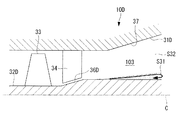
例えば、図7に示すように、軸流ブロワ(回転機械)10Eの回転軸(ロータ)32Eに形成された縮小流路部36Eを、静翼34よりも下流側に設けても良い。
(Modified example of the second reference embodiment)
In the second reference embodiment, the reduced
For example, as shown in FIG. 7, the reduced
〔第3参考実施形態〕
次に、本発明に係る回転機械、回転機械の排気部材の第3参考実施形態について説明する。
図8に示すように、軸流タービン(回転機械)10Fは、タービンハウジング41と、ロータ42と、静翼43と、動翼(回転翼)44と、排気ケーシング(ケーシング)45と、を備えている。
[ Third Reference Embodiment]
Next, a third reference embodiment of the rotary machine and the exhaust member of the rotary machine according to the present invention will be described.
As shown in FIG. 8, the axial flow turbine (rotary machine) 10F includes a
タービンハウジング41は、中心軸C方向に沿って延びる筒状をなしている。
静翼43は、タービンハウジング41の内側に、中心軸C回りの周方向に間隔を空けて複数が設けられている。各静翼43は、タービンハウジング41から内周側に向かって延びるように形成されている。
The
A plurality of
ロータ42は、図示しない軸受によって中心軸C回りに回転可能に支持されている。
動翼44は、ロータ42の外周部に、中心軸C回りの周方向に間隔を空けて複数が設けられている。各動翼44は、ロータ42の外周面から径方向外側に延びるように形成されている。動翼44は、中心軸C方向において、静翼43の下流側に配置されている。
The
A plurality of
排気ケーシング45は、タービンハウジング41の下流側に接続されている。排気ケーシング45は、動翼44の径方向外側に位置する外周ケーシング部45aと、外周ケーシング部45aに対して径方向内側に間隔をあけて設けられた内周ケーシング部45bと、を備えている。内周ケーシング部45bは、中心軸C方向に沿って延びる筒状をなし、ロータ42の回転軸42sの外周側に設けられている。これら排気ケーシング45の外周ケーシング部の内周面と内周ケーシング部45bの外周面との間の断面環状の領域に、作動流体の排気流路104が形成される。
The
上記排気ケーシング45は、これらの静翼43および動翼44よりも流れ方向の下流側に向かって延びている。内周ケーシング部45bの外周面には、静翼43および動翼44よりも下流側に、縮小流路部46が形成されている。また、タービンハウジング41の内周面には、縮小流路部46よりも下流側に、拡大流路部47が形成されている。
The
縮小流路部46は、下流側に向かって内周ケーシング部45bの外径が拡大することで、作動流体の流路断面積が漸次縮小している。
拡大流路部47は、縮小流路部46の下流側に設けられ、下流側に向かって外周ケーシング部45aの内径および内周ケーシング部45bの外径が漸次拡大することで、作動流体の流路断面積が漸次拡大している。
In the reduced
The expansion
上述したような軸流タービン10Fによれば、静翼43、動翼44を経た作動流体は、その流れ方向の下流側に縮小流路部46が設けられることで、作動流体の流路が狭まる。これによって、動翼44の下流側で剥離が生じ得る領域が相対的に減少する。このような縮小流路部46を経た後に、拡大流路部47にて作動流体の流路断面積を漸次拡大させることで、作動流体の圧力回復の効率を高めることができる。
According to the
なお、上記実施形態又は参考実施形態において、ラジアルタービン10A、10Bと、軸流ブロワ10C、10D、軸流タービン10Fを例示したが、本発明の参考例は、例えば斜流式タービン等、上記した以外の回転機械に適用可能である。また、ラジアルタービン10A、10B、軸流ブロワ10C、10D、軸流タービン10Fは、各部の構成を、上記実施形態およびその変形例で示した構成と異ならせても良い。
また、縮小流路部は、回転翼よりも作動流体の流れ方向の下流側に設けられるのであれば、縮小流路部を形成する凸形状はケーシング側、ロータ側のどちら側に設けてもよく、ケーシング側とロータ側の双方に凸形状を設けてもよい。
さらに、ケーシングは、単一部品で構成しても良いし、複数部品を組み合わせることで構成しても良い。
In the above-described embodiment or reference embodiment , the
Further, if the reduced flow path portion is provided on the downstream side of the rotary blade in the flow direction of the working fluid, the convex shape forming the reduced flow path portion may be provided on either the casing side or the rotor side. , A convex shape may be provided on both the casing side and the rotor side.
Further, the casing may be composed of a single component or a combination of a plurality of components.
上記第1実施形態で示したような構成について、効果を確認したので、以下に、その結果を示す。
実施例としては、L字状の排気部材を用いた。この排気部材は、下流側に向かってその内径が漸次拡大する拡大流路部の上流側に、縮小流路部を備えている。
比較例として、拡径流路部の上流側に、下流側に向かってその内径が漸次縮小する縮小流路部を備えていない排気部材を用いた。
Since the effects of the configuration shown in the first embodiment have been confirmed, the results are shown below.
As an example, an L-shaped exhaust member was used. This exhaust member is provided with a reduced flow path portion on the upstream side of the enlarged flow path portion whose inner diameter gradually expands toward the downstream side.
As a comparative example, an exhaust member having no reduced flow path portion whose inner diameter gradually decreases toward the downstream side was used on the upstream side of the expanded flow path portion.
上記の実施例および比較例について、コンピュータ解析により、排気部材の内部における流速分布を求めた。
その結果を、図9および図10に示す。
For the above Examples and Comparative Examples, the flow velocity distribution inside the exhaust member was determined by computer analysis.
The results are shown in FIGS. 9 and 10.
図9に示すように、縮小流路部を有した実施例においては、図10に示す比較例と比較すると、縮小流路部において、流路中央部の流速が低い部分が縮小している。したがって、流路内で剥離が生じる領域を低減し、その下流側の拡大流路部において圧力回復の効率が高まる。 As shown in FIG. 9, in the embodiment having the reduced flow path portion, the portion of the reduced flow path portion where the flow velocity is low is reduced as compared with the comparative example shown in FIG. Therefore, the region where peeling occurs in the flow path is reduced, and the efficiency of pressure recovery is increased in the enlarged flow path portion on the downstream side thereof.
10A、10B ラジアルタービン(回転機械)
10C、10D、10E 軸流ブロワ(回転機械)
10F 軸流タービン(回転機械)
11 ケーシング
12 ロータ
13 回転翼
14g 端面(端部)
15A、15B 排気部材(排出部、排気部材本体)
15f 内周面
16、22、36C、36D、36E 縮小流路部
17、37 拡大流路部
23 第二拡大流路部(拡大流路部)
31C、31D ケーシング
31f 内周面
32、32D、32E 回転軸(ロータ)
33 動翼(回転翼)
34 静翼
42 ロータ
43 静翼
44 動翼(回転翼)
45 排気ケーシング(ケーシング)
C 中心軸
10A, 10B radial turbine (rotary machine)
10C, 10D, 10E Axial flow blower (rotary machine)
10F Axial turbine (rotary machine)
11
15A, 15B Exhaust member (exhaust part, exhaust member body)
15f Inner
31C,
33 Moving blades (rotor blades)
34
45 Exhaust casing (casing)
C central axis
Claims (3)
前記ロータの外周部に固定された回転翼と、
前記ロータおよび前記回転翼の外周側に設けられ、その内側に作動流体の流路を形成するケーシングと、
前記回転翼よりも前記作動流体の流れ方向の下流側に設けられ、下流側に向かって前記作動流体の流路断面積が漸次縮小する縮小流路部と、
前記縮小流路部の下流側に設けられ、下流側に向かって前記作動流体の流路断面積が漸次拡大する拡大流路部と、
を備え、
前記縮小流路部の前記流れ方向における長さは、前記回転翼の出口幅よりも小さくされ、
前記縮小流路部による前記流路の縮径量は、前記回転翼の前記出口幅よりも小さくされていることを特徴とするラジアルタービン。 A rotor that is rotatably provided around the central axis and
The rotor blades fixed to the outer circumference of the rotor and
A casing provided on the outer peripheral side of the rotor and the rotary blade and forming a flow path for a working fluid inside the rotor and the casing.
A reduced flow path portion provided on the downstream side of the rotary blade in the flow direction of the working fluid and the flow path cross-sectional area of the working fluid gradually shrinks toward the downstream side.
An enlarged flow path portion provided on the downstream side of the reduced flow path portion and gradually expanding the flow path cross-sectional area of the working fluid toward the downstream side.
Equipped with a,
The length of the reduced flow path portion in the flow direction is made smaller than the outlet width of the rotary blade.
The diameter reduction of the flow path by reducing channel portion, a radial turbine which is characterized that you have been smaller than the outlet width of said rotating blade.
前記縮小流路部および前記拡大流路部は、前記排出部において前記ロータの前記流れ方向下流側の端部よりも下流側に形成されていることを特徴とする請求項1に記載のラジアルタービン。 Further provided with a discharge portion extending toward the downstream side of the rotor and the rotary blade and discharging the working fluid to the downstream side.
The radial turbine according to claim 1, wherein the reduced flow path portion and the expanded flow path portion are formed in the discharge portion on the downstream side of the end portion on the downstream side in the flow direction of the rotor. ..
前記ロータ及び前記回転翼よりも下流側に向かって延びるよう設けられ、前記作動流体を下流側に排出する排気流路を形成する筒状の排気部材本体と、
前記排気部材本体の内周面に形成され、前記作動流体の流れ方向の下流側に向かって前記作動流体の流路断面積が漸次縮小する縮小流路部と、
前記排気部材本体の内周面の前記縮小流路部よりも下流側に形成され、下流側に向かって前記作動流体の流路断面積が漸次拡大する拡大流路部と、
を備え、
前記縮小流路部の前記流れ方向における長さは、前記回転翼の出口幅よりも小さくされ、
前記縮小流路部による前記流路の縮径量は、前記回転翼の前記出口幅よりも小さくされていることを特徴とするラジアルタービンの排気部材。 A rotor rotatably provided around the central axis, a rotary blade fixed to the outer peripheral portion of the rotor, and a casing provided on the outer peripheral side of the rotary blade and forming a flow path for a working fluid are provided inside the rotor. It is an exhaust member of a radial turbine and
A tubular exhaust member main body provided so as to extend toward the downstream side of the rotor and the rotary blade and forming an exhaust flow path for discharging the working fluid to the downstream side.
A reduced flow path portion formed on the inner peripheral surface of the exhaust member main body and gradually reducing the flow path cross-sectional area of the working fluid toward the downstream side in the flow direction of the working fluid.
An enlarged flow path portion formed on the inner peripheral surface of the exhaust member main body on the downstream side of the reduced flow path portion, and the flow path cross-sectional area of the working fluid gradually expands toward the downstream side.
Equipped with a,
The length of the reduced flow path portion in the flow direction is made smaller than the outlet width of the rotary blade.
The diameter reduction of the flow path by reducing channel section, an exhaust member of the radial turbine is characterized that you have been smaller than the outlet width of said rotating blade.
Priority Applications (4)
| Application Number | Priority Date | Filing Date | Title |
|---|---|---|---|
| JP2017035465A JP6776154B2 (en) | 2017-02-27 | 2017-02-27 | Radial turbine, exhaust parts of radial turbine |
| PCT/JP2018/004248 WO2018155189A1 (en) | 2017-02-27 | 2018-02-07 | Rotating machine and exhaust member of rotating machine |
| CN201880003439.6A CN110300839A (en) | 2017-02-27 | 2018-02-07 | The exhaust component of rotating machinery, rotating machinery |
| KR1020197005713A KR102223293B1 (en) | 2017-02-27 | 2018-02-07 | Rotating machine, exhaust member of rotating machine |
Applications Claiming Priority (1)
| Application Number | Priority Date | Filing Date | Title |
|---|---|---|---|
| JP2017035465A JP6776154B2 (en) | 2017-02-27 | 2017-02-27 | Radial turbine, exhaust parts of radial turbine |
Publications (2)
| Publication Number | Publication Date |
|---|---|
| JP2018141399A JP2018141399A (en) | 2018-09-13 |
| JP6776154B2 true JP6776154B2 (en) | 2020-10-28 |
Family
ID=63254191
Family Applications (1)
| Application Number | Title | Priority Date | Filing Date |
|---|---|---|---|
| JP2017035465A Active JP6776154B2 (en) | 2017-02-27 | 2017-02-27 | Radial turbine, exhaust parts of radial turbine |
Country Status (4)
| Country | Link |
|---|---|
| JP (1) | JP6776154B2 (en) |
| KR (1) | KR102223293B1 (en) |
| CN (1) | CN110300839A (en) |
| WO (1) | WO2018155189A1 (en) |
Families Citing this family (1)
| Publication number | Priority date | Publication date | Assignee | Title |
|---|---|---|---|---|
| US11808174B2 (en) | 2020-04-23 | 2023-11-07 | Mitsubishi Heavy Industries Engine & Turbocharger, Ltd. | Turbine and turbocharger including the turbine |
Family Cites Families (9)
| Publication number | Priority date | Publication date | Assignee | Title |
|---|---|---|---|---|
| US3625630A (en) * | 1970-03-27 | 1971-12-07 | Caterpillar Tractor Co | Axial flow diffuser |
| JPS5040156B1 (en) | 1971-05-06 | 1975-12-22 | ||
| JPH07247996A (en) * | 1994-03-11 | 1995-09-26 | Ishikawajima Harima Heavy Ind Co Ltd | Passage form of compressor |
| CN101092978A (en) * | 2007-07-30 | 2007-12-26 | 北京航空航天大学 | Synergic action device of preventing breath heavily and expanding stability of airbleed inside stator of multistage axial flow air compresdsor |
| FR2940413B1 (en) * | 2008-12-19 | 2013-01-11 | Air Liquide | METHOD OF CAPTURING CO2 BY CRYO-CONDENSATION |
| US8328513B2 (en) * | 2009-12-31 | 2012-12-11 | General Electric Company | Systems and apparatus relating to compressor stator blades and diffusers in turbine engines |
| EP2407638A1 (en) * | 2010-07-15 | 2012-01-18 | Siemens Aktiengesellschaft | Exhaust gas diffuser for a gas turbine and method for operating a gas turbine with such an exhaust gas diffuser |
| JP6169007B2 (en) * | 2014-01-23 | 2017-07-26 | 三菱重工業株式会社 | Rotor blade and axial flow rotating machine |
| US9759230B2 (en) * | 2014-01-24 | 2017-09-12 | Pratt & Whitney Canada Corp. | Multistage axial flow compressor |
-
2017
- 2017-02-27 JP JP2017035465A patent/JP6776154B2/en active Active
-
2018
- 2018-02-07 WO PCT/JP2018/004248 patent/WO2018155189A1/en active Application Filing
- 2018-02-07 CN CN201880003439.6A patent/CN110300839A/en active Pending
- 2018-02-07 KR KR1020197005713A patent/KR102223293B1/en active IP Right Grant
Also Published As
| Publication number | Publication date |
|---|---|
| KR102223293B1 (en) | 2021-03-04 |
| KR20190032554A (en) | 2019-03-27 |
| JP2018141399A (en) | 2018-09-13 |
| CN110300839A (en) | 2019-10-01 |
| WO2018155189A1 (en) | 2018-08-30 |
Similar Documents
| Publication | Publication Date | Title |
|---|---|---|
| US7665964B2 (en) | Turbine | |
| JP5019721B2 (en) | Method and apparatus for assembling a gas turbine engine | |
| CA2496543C (en) | Recirculation structure for a turbocompressor | |
| US9039357B2 (en) | Seal assembly including grooves in a radially outwardly facing side of a platform in a gas turbine engine | |
| JP3105277B2 (en) | Axial gas turbine | |
| EP2948639B1 (en) | Seal assembly including grooves in an inner shroud in a gas turbine engine | |
| JPS5810600B2 (en) | Axial compressor casing | |
| JP2012233475A (en) | Centrifugal compressor assembly with stator vane row | |
| CA2927035C (en) | Rotor assembly with wear member | |
| CA2927037C (en) | Rotor assembly with scoop | |
| JP6265353B2 (en) | On-off valve device and rotating machine | |
| JP2018173020A (en) | Centrifugal compressor | |
| EP2971547B1 (en) | Cantilever stator with vortex initiation feature | |
| EP3561312B1 (en) | Centrifugal compressor | |
| JP6776154B2 (en) | Radial turbine, exhaust parts of radial turbine | |
| EP3967848B1 (en) | Steam turbine with exhaust diffuser | |
| EP2778346B1 (en) | Rotor for a gas turbine engine, corresponding gas turbine engine and method of improving gas turbine engine rotor efficiency | |
| CN110475948B (en) | Gas turbine | |
| JP6449218B2 (en) | Transition ducts, turbines, and gas turbine engines | |
| JP3034519B1 (en) | Gas turbine with improved cooling structure of turbine rotor | |
| JP3380897B2 (en) | Compressor | |
| JP6768172B1 (en) | Centrifugal compressor | |
| JPS6332963B2 (en) | ||
| JPH07279887A (en) | Axial flow air compressor | |
| JP6820735B2 (en) | Turbines and gas turbines |
Legal Events
| Date | Code | Title | Description |
|---|---|---|---|
| A621 | Written request for application examination |
Free format text: JAPANESE INTERMEDIATE CODE: A621 Effective date: 20190215 |
|
| A131 | Notification of reasons for refusal |
Free format text: JAPANESE INTERMEDIATE CODE: A131 Effective date: 20191112 |
|
| A521 | Written amendment |
Free format text: JAPANESE INTERMEDIATE CODE: A523 Effective date: 20200114 |
|
| A711 | Notification of change in applicant |
Free format text: JAPANESE INTERMEDIATE CODE: A711 Effective date: 20200325 |
|
| A131 | Notification of reasons for refusal |
Free format text: JAPANESE INTERMEDIATE CODE: A131 Effective date: 20200602 |
|
| A521 | Written amendment |
Free format text: JAPANESE INTERMEDIATE CODE: A523 Effective date: 20200716 |
|
| TRDD | Decision of grant or rejection written | ||
| A01 | Written decision to grant a patent or to grant a registration (utility model) |
Free format text: JAPANESE INTERMEDIATE CODE: A01 Effective date: 20200908 |
|
| A61 | First payment of annual fees (during grant procedure) |
Free format text: JAPANESE INTERMEDIATE CODE: A61 Effective date: 20201007 |
|
| R150 | Certificate of patent or registration of utility model |
Ref document number: 6776154 Country of ref document: JP Free format text: JAPANESE INTERMEDIATE CODE: R150 |