JP6775464B2 - Extruder assembly for 3D object printers - Google Patents
Extruder assembly for 3D object printers Download PDFInfo
- Publication number
- JP6775464B2 JP6775464B2 JP2017081696A JP2017081696A JP6775464B2 JP 6775464 B2 JP6775464 B2 JP 6775464B2 JP 2017081696 A JP2017081696 A JP 2017081696A JP 2017081696 A JP2017081696 A JP 2017081696A JP 6775464 B2 JP6775464 B2 JP 6775464B2
- Authority
- JP
- Japan
- Prior art keywords
- extruder
- extrusion slot
- actuator
- slot
- extrusion
- Prior art date
- Legal status (The legal status is an assumption and is not a legal conclusion. Google has not performed a legal analysis and makes no representation as to the accuracy of the status listed.)
- Active
Links
- 238000001125 extrusion Methods 0.000 claims description 76
- 239000000463 material Substances 0.000 claims description 28
- 238000004519 manufacturing process Methods 0.000 description 23
- 238000000034 method Methods 0.000 description 21
- 230000015572 biosynthetic process Effects 0.000 description 5
- 230000000712 assembly Effects 0.000 description 4
- 238000000429 assembly Methods 0.000 description 4
- 230000001788 irregular Effects 0.000 description 2
- 239000000654 additive Substances 0.000 description 1
- 230000000996 additive effect Effects 0.000 description 1
- 230000009286 beneficial effect Effects 0.000 description 1
- 238000010586 diagram Methods 0.000 description 1
- 239000007787 solid Substances 0.000 description 1
- 239000000758 substrate Substances 0.000 description 1
Images


Classifications
-
- B—PERFORMING OPERATIONS; TRANSPORTING
- B29—WORKING OF PLASTICS; WORKING OF SUBSTANCES IN A PLASTIC STATE IN GENERAL
- B29C—SHAPING OR JOINING OF PLASTICS; SHAPING OF MATERIAL IN A PLASTIC STATE, NOT OTHERWISE PROVIDED FOR; AFTER-TREATMENT OF THE SHAPED PRODUCTS, e.g. REPAIRING
- B29C64/00—Additive manufacturing, i.e. manufacturing of three-dimensional [3D] objects by additive deposition, additive agglomeration or additive layering, e.g. by 3D printing, stereolithography or selective laser sintering
- B29C64/30—Auxiliary operations or equipment
- B29C64/307—Handling of material to be used in additive manufacturing
- B29C64/321—Feeding
-
- B—PERFORMING OPERATIONS; TRANSPORTING
- B29—WORKING OF PLASTICS; WORKING OF SUBSTANCES IN A PLASTIC STATE IN GENERAL
- B29C—SHAPING OR JOINING OF PLASTICS; SHAPING OF MATERIAL IN A PLASTIC STATE, NOT OTHERWISE PROVIDED FOR; AFTER-TREATMENT OF THE SHAPED PRODUCTS, e.g. REPAIRING
- B29C48/00—Extrusion moulding, i.e. expressing the moulding material through a die or nozzle which imparts the desired form; Apparatus therefor
- B29C48/02—Small extruding apparatus, e.g. handheld, toy or laboratory extruders
-
- B—PERFORMING OPERATIONS; TRANSPORTING
- B29—WORKING OF PLASTICS; WORKING OF SUBSTANCES IN A PLASTIC STATE IN GENERAL
- B29C—SHAPING OR JOINING OF PLASTICS; SHAPING OF MATERIAL IN A PLASTIC STATE, NOT OTHERWISE PROVIDED FOR; AFTER-TREATMENT OF THE SHAPED PRODUCTS, e.g. REPAIRING
- B29C48/00—Extrusion moulding, i.e. expressing the moulding material through a die or nozzle which imparts the desired form; Apparatus therefor
- B29C48/16—Articles comprising two or more components, e.g. co-extruded layers
- B29C48/18—Articles comprising two or more components, e.g. co-extruded layers the components being layers
- B29C48/21—Articles comprising two or more components, e.g. co-extruded layers the components being layers the layers being joined at their surfaces
-
- B—PERFORMING OPERATIONS; TRANSPORTING
- B29—WORKING OF PLASTICS; WORKING OF SUBSTANCES IN A PLASTIC STATE IN GENERAL
- B29C—SHAPING OR JOINING OF PLASTICS; SHAPING OF MATERIAL IN A PLASTIC STATE, NOT OTHERWISE PROVIDED FOR; AFTER-TREATMENT OF THE SHAPED PRODUCTS, e.g. REPAIRING
- B29C48/00—Extrusion moulding, i.e. expressing the moulding material through a die or nozzle which imparts the desired form; Apparatus therefor
- B29C48/25—Component parts, details or accessories; Auxiliary operations
- B29C48/266—Means for allowing relative movements between the apparatus parts, e.g. for twisting the extruded article or for moving the die along a surface to be coated
-
- B—PERFORMING OPERATIONS; TRANSPORTING
- B29—WORKING OF PLASTICS; WORKING OF SUBSTANCES IN A PLASTIC STATE IN GENERAL
- B29C—SHAPING OR JOINING OF PLASTICS; SHAPING OF MATERIAL IN A PLASTIC STATE, NOT OTHERWISE PROVIDED FOR; AFTER-TREATMENT OF THE SHAPED PRODUCTS, e.g. REPAIRING
- B29C48/00—Extrusion moulding, i.e. expressing the moulding material through a die or nozzle which imparts the desired form; Apparatus therefor
- B29C48/25—Component parts, details or accessories; Auxiliary operations
- B29C48/92—Measuring, controlling or regulating
-
- B—PERFORMING OPERATIONS; TRANSPORTING
- B29—WORKING OF PLASTICS; WORKING OF SUBSTANCES IN A PLASTIC STATE IN GENERAL
- B29C—SHAPING OR JOINING OF PLASTICS; SHAPING OF MATERIAL IN A PLASTIC STATE, NOT OTHERWISE PROVIDED FOR; AFTER-TREATMENT OF THE SHAPED PRODUCTS, e.g. REPAIRING
- B29C64/00—Additive manufacturing, i.e. manufacturing of three-dimensional [3D] objects by additive deposition, additive agglomeration or additive layering, e.g. by 3D printing, stereolithography or selective laser sintering
- B29C64/20—Apparatus for additive manufacturing; Details thereof or accessories therefor
- B29C64/205—Means for applying layers
- B29C64/209—Heads; Nozzles
-
- B—PERFORMING OPERATIONS; TRANSPORTING
- B29—WORKING OF PLASTICS; WORKING OF SUBSTANCES IN A PLASTIC STATE IN GENERAL
- B29C—SHAPING OR JOINING OF PLASTICS; SHAPING OF MATERIAL IN A PLASTIC STATE, NOT OTHERWISE PROVIDED FOR; AFTER-TREATMENT OF THE SHAPED PRODUCTS, e.g. REPAIRING
- B29C64/00—Additive manufacturing, i.e. manufacturing of three-dimensional [3D] objects by additive deposition, additive agglomeration or additive layering, e.g. by 3D printing, stereolithography or selective laser sintering
- B29C64/30—Auxiliary operations or equipment
- B29C64/307—Handling of material to be used in additive manufacturing
- B29C64/343—Metering
-
- B—PERFORMING OPERATIONS; TRANSPORTING
- B33—ADDITIVE MANUFACTURING TECHNOLOGY
- B33Y—ADDITIVE MANUFACTURING, i.e. MANUFACTURING OF THREE-DIMENSIONAL [3-D] OBJECTS BY ADDITIVE DEPOSITION, ADDITIVE AGGLOMERATION OR ADDITIVE LAYERING, e.g. BY 3-D PRINTING, STEREOLITHOGRAPHY OR SELECTIVE LASER SINTERING
- B33Y50/00—Data acquisition or data processing for additive manufacturing
- B33Y50/02—Data acquisition or data processing for additive manufacturing for controlling or regulating additive manufacturing processes
-
- B—PERFORMING OPERATIONS; TRANSPORTING
- B29—WORKING OF PLASTICS; WORKING OF SUBSTANCES IN A PLASTIC STATE IN GENERAL
- B29C—SHAPING OR JOINING OF PLASTICS; SHAPING OF MATERIAL IN A PLASTIC STATE, NOT OTHERWISE PROVIDED FOR; AFTER-TREATMENT OF THE SHAPED PRODUCTS, e.g. REPAIRING
- B29C64/00—Additive manufacturing, i.e. manufacturing of three-dimensional [3D] objects by additive deposition, additive agglomeration or additive layering, e.g. by 3D printing, stereolithography or selective laser sintering
- B29C64/10—Processes of additive manufacturing
- B29C64/106—Processes of additive manufacturing using only liquids or viscous materials, e.g. depositing a continuous bead of viscous material
- B29C64/118—Processes of additive manufacturing using only liquids or viscous materials, e.g. depositing a continuous bead of viscous material using filamentary material being melted, e.g. fused deposition modelling [FDM]
-
- B—PERFORMING OPERATIONS; TRANSPORTING
- B29—WORKING OF PLASTICS; WORKING OF SUBSTANCES IN A PLASTIC STATE IN GENERAL
- B29L—INDEXING SCHEME ASSOCIATED WITH SUBCLASS B29C, RELATING TO PARTICULAR ARTICLES
- B29L2009/00—Layered products
-
- B—PERFORMING OPERATIONS; TRANSPORTING
- B33—ADDITIVE MANUFACTURING TECHNOLOGY
- B33Y—ADDITIVE MANUFACTURING, i.e. MANUFACTURING OF THREE-DIMENSIONAL [3-D] OBJECTS BY ADDITIVE DEPOSITION, ADDITIVE AGGLOMERATION OR ADDITIVE LAYERING, e.g. BY 3-D PRINTING, STEREOLITHOGRAPHY OR SELECTIVE LASER SINTERING
- B33Y10/00—Processes of additive manufacturing
-
- B—PERFORMING OPERATIONS; TRANSPORTING
- B33—ADDITIVE MANUFACTURING TECHNOLOGY
- B33Y—ADDITIVE MANUFACTURING, i.e. MANUFACTURING OF THREE-DIMENSIONAL [3-D] OBJECTS BY ADDITIVE DEPOSITION, ADDITIVE AGGLOMERATION OR ADDITIVE LAYERING, e.g. BY 3-D PRINTING, STEREOLITHOGRAPHY OR SELECTIVE LASER SINTERING
- B33Y30/00—Apparatus for additive manufacturing; Details thereof or accessories therefor
Description
本明細書において開示されるシステムおよび方法は、三次元物体を製造するプリンタに関し、より詳しくは、そのようなプリンタのための押出機アセンブリに関する。 The systems and methods disclosed herein relate to printers that manufacture three-dimensional objects, and more specifically to extruder assemblies for such printers.
デジタル付加製造としても知られるデジタル三次元製造は、デジタルモデルから実質的に任意の形状の三次元の固形の物体を製作するプロセスである。三次元物体の印刷は、1つ以上の押出機または排出機アセンブリが材料の逐次の層をさまざまな形状にて基板上に形成する付加プロセスである。いくつかの従来からの三次元物体プリンタにおいては、層を形成すべく材料の液滴を排出する排出機のアレイよりはむしろ、層を形成すべく材料の連続的な流れを放つ押出機のアレイを備える点で、押出機が文書プリンタの印刷ヘッドに類似している。 Digital three-dimensional manufacturing, also known as digital additive manufacturing, is the process of producing a three-dimensional solid object of virtually any shape from a digital model. Printing a three-dimensional object is an additional process in which one or more extruder or ejector assemblies form successive layers of material on a substrate in various shapes. In some traditional 3D object printers, an array of extruders that emits a continuous stream of material to form a layer, rather than an array of ejectors that eject droplets of material to form a layer. The extruder is similar to the printhead of a document printer in that it comprises.
他の公知の三次元物体プリンタにおいては、押出機アセンブリが、印刷による物体を生成するための層を形成するために製作材料を押し出すように構成されたただ1つのノズルを備える。ノズルは、一般に、製作材料の連続的なフィラメントを放つ小さな円形の穴として構成される。フィラメントが、層ごとのやり方で配置され、三次元の部品を形成する。そのような押出機アセンブリにおいて、印刷による物体は、迅速かつ正確に形成されなければならない。ノズルの直径が、部品の最小解像度および物体の可能な形成速度の両方を決定する。例えば、ノズルの直径が大きいほど、物体をより迅速に形成することができるが、解像度が低くなる一方で、ノズルの直径が小さいほど、より小さな細部を形成することができるが、製品の製造により多くの時間が必要になる。このように、従来からの三次元物体プリンタにおいては、ノズルのサイズが、製作の速度と製作の解像度との間の妥協を呈する。 In other known three-dimensional object printers, the extruder assembly comprises a single nozzle configured to extrude the material to form a layer for producing an object by printing. Nozzles are generally constructed as small circular holes that emit continuous filaments of material. The filaments are arranged in a layer-by-layer manner to form a three-dimensional component. In such extruder assemblies, printed objects must be formed quickly and accurately. The diameter of the nozzle determines both the minimum resolution of the part and the possible rate of formation of the object. For example, the larger the nozzle diameter, the faster the object can be formed, while the lower the resolution, the smaller the nozzle diameter, the smaller details can be formed, depending on the manufacture of the product. It takes a lot of time. Thus, in traditional 3D object printers, the size of the nozzle presents a compromise between production speed and production resolution.
したがって、押出機アセンブリを備えるプリンタで三次元物体を形成するためのシステムおよび方法において、物体をさらに精緻にし、製造時間を短縮する改善が、有益であると考えられる。 Therefore, in systems and methods for forming three-dimensional objects in printers with extruder assemblies, improvements to further refine the objects and reduce manufacturing time would be beneficial.
一実施形態においては、三次元物体のための押出機アセンブリが、より高い精密さでのより高速な三次元物体の印刷を可能にするために押し出しスロットを有する。印刷システムは、材料の連続的なフィラメントを押し出すことを可能にするための押し出しスロットを有している押出機本体と、押出機本体に動作可能に接続された少なくとも1つのアクチュエータとを備える。少なくとも1つのアクチュエータは、押出機本体を水平面内で平行移動させ、回転軸を中心にして押出機本体を回転させるように構成される。 In one embodiment, the extruder assembly for a 3D object has an extrusion slot to allow faster printing of the 3D object with higher precision. The printing system comprises an extruder body having an extrusion slot for allowing continuous filaments of material to be extruded, and at least one actuator operably connected to the extruder body. At least one actuator is configured to translate the extruder body in a horizontal plane and rotate the extruder body about a rotation axis.
別の実施形態においては、三次元の製作物体を形成する方法が、より高い精密さでのより高速な三次元物体の印刷を可能にする。この方法は、押出機アセンブリの押出機本体の押し出しスロットを通って製作材料を押し出すステップと、製作材料を押し出しつつ、押出機本体を少なくとも1つのアクチュエータによって水平面内で平行移動させることで、製作材料の連続的なリボンを形成するステップと、製作材料を押し出しつつ、押出機本体を少なくとも1つのアクチュエータによって回転軸を中心にして回転させるステップとを含む。 In another embodiment, the method of forming a three-dimensional object allows faster printing of the three-dimensional object with higher precision. This method involves extruding the material through the extrusion slot of the extruder body of the extruder assembly and translating the material in the horizontal plane with at least one actuator while extruding the material. It includes a step of forming a continuous ribbon of the above and a step of rotating the extruder body about a rotation axis by at least one actuator while extruding the material to be manufactured.
本開示によるさらに別の実施形態においては、三次元物体印刷システムのための押出機アセンブリが、押し出しスロットと、より良好な三次元物体の印刷精度およびより高速な製作時間のために押し出しスロットの押し出し面積の調節を可能にするシャッタ本体とを有する。印刷システムは、押出機本体と、少なくとも1つの第1のアクチュエータと、少なくとも1つのシャッタ本体と、第2のアクチュエータとを備える。押出機本体は、材料の連続的なフィラメントの押し出しを可能にするための押し出しスロットを有する。少なくとも1つの第1のアクチュエータは、押出機へと動作可能に接続され、押出機本体を水平面内で平行移動させるように構成される。第2のアクチュエータは、少なくとも1つのシャッタ本体へと動作可能に接続され、押し出しスロットの第1の部分を閉じ、押し出しスロットを通って押し出されるフィラメントの幅を小さくするように、押し出しスロットを選択的に覆うように少なくとも1つのシャッタ本体を移動させるように構成される。 In yet another embodiment according to the present disclosure, the extruder assembly for a 3D object printing system is an extrusion slot and an extrusion of the extrusion slot for better printing accuracy of the 3D object and faster fabrication time. It has a shutter body that allows the area to be adjusted. The printing system includes an extruder body, at least one first actuator, at least one shutter body, and a second actuator. The extruder body has an extrusion slot to allow continuous filament extrusion of the material. The at least one first actuator is operably connected to the extruder and is configured to translate the extruder body in a horizontal plane. The second actuator is operably connected to at least one shutter body, closing the first portion of the extrusion slot and selectively selecting the extrusion slot to reduce the width of the filament extruded through the extrusion slot. It is configured to move at least one shutter body so as to cover it.
押出機を有するプリンタおよび押出機を有するプリンタを動作させるための方法の上述の態様および他の特徴が、以下の説明において解説され、添付の図面との関連において理解される。 The above aspects and other features of a printer with an extruder and a method for operating a printer with an extruder are described in the following description and understood in the context of the accompanying drawings.
本明細書に開示されるシステムおよび方法に関する環境ならびにそれらのシステムおよび方法に関する詳細の全体的な理解のために、図面が参照される。図面においては、類似の参照番号が、類似の要素を指し示すために全体を通して使用されている。 The drawings are referenced for an overall understanding of the environment for the systems and methods disclosed herein and the details of those systems and methods. In the drawings, similar reference numbers are used throughout to point to similar elements.
図1が、三次元物体プリンタ100を示している。三次元物体プリンタ100は、アクチュエータアセンブリ104、押出機アセンブリ108、プラテン112、およびコントローラ116を備えている。アクチュエータアセンブリ104は、少なくとも1つのアクチュエータ120と、支持フレーム(図示されていない)に取り付けられた1対のレール124とを備えている。レール124は、アクチュエータ120によって押出機アセンブリ108をx軸128、y軸132、およびz軸136に沿って平行移動させ、かつ押出機アセンブリ108を図示の実施形態においてはz軸136に平行である回転軸140を中心にして回転させることができるように、アクチュエータ120および押出機アセンブリ108を支持するように構成されている。
FIG. 1 shows a three-
図1の実施形態において、アクチュエータアセンブリ104は、押出機アセンブリ108をx軸128、y軸132、およびz軸136にて平行移動させるように構成されたただ1つのアクチュエータ120を備えており、アクチュエータ120は、回転軸140を中心にしてアクチュエータを回転させるように構成されている。別の実施形態において、アクチュエータアセンブリ104は、押出機アセンブリ108をx軸128、y軸132、およびz軸136にて移動させるように構成された第1のアクチュエータと、回転軸140を中心にして押出機アセンブリ108を回転させるように構成された第2のアクチュエータとを備える。図18に示されるさらに別の実施形態においては、アクチュエータアセンブリ104Aが、押出機本体160をx方向128に移動させるように構成された第1のアクチュエータ120Xと、押出機本体160をy方向132に移動させるように構成された第2のアクチュエータ120Yと、押出機本体160をz方向136に移動させるように構成された第3のアクチュエータ120Zと、回転軸140を中心にして押出機本体160を回転させるように構成された第4のアクチュエータ120Rとを備える。
In the embodiment of FIG. 1, the
再び図1を参照すると、押出機アセンブリ108は、押出機本体160と、製作材料を貯蔵するように構成されたリザーバ164とを備える。押し出しスロット168(図1の図では比例尺では示されていない)が、押出機本体160の下部に定められている。押し出しスロット168は、リザーバ164へと動作可能に接続され、リザーバ164から受け取った製作材料を押し出して、プラテン112上に製作物体180を形成するように構成されている。一実施形態において、押し出しスロット168の長さは、約0.75mm〜約6.4mmの間であり、押し出しスロットの幅は、約0.2mm〜約0.5mmの間である。別の特定の実施形態においては、押し出しスロット168の長さが、約1.2mmであり、押し出しスロットの幅が、約0.3mmである。いくつかの実施形態において、押し出しスロット168は、プラテン112の表面の平面に平行であるように構成され、軸140を中心とする回転は、スロットをプラテンの表面に対して平行な向きに維持する。いくつかの状況における回転は、押し出されるリボンの所望のサイズに基づき、押出機の移動方向に関連して調節される。
With reference to FIG. 1 again, the
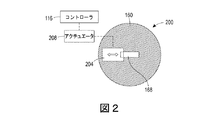
いくつかの実施形態において、押出機本体160は、押し出しスロットまたはその一部分を閉じるためのシャッタシステムを備える。押出機本体160において使用するための種々のシャッタシステム200、220、240、260、280が、図2〜図9に示されている。図2が、平坦なシャッタ本体204を有しているシャッタシステム200を示している。平坦なシャッタ本体204は、スロットの一部分を閉じるべく、スロット168を横切って直線的に平坦なシャッタ本体204をスライドさせるように構成されたアクチュエータ208へと動作可能に接続されている。アクチュエータ208は、詳しくは後述されるように、押し出されるリボンの所望のサイズに基づいて平坦なシャッタ本体204の位置を設定すべくアクチュエータ208を動作させるように構成されたコントローラ116へと動作可能に接続されている。
In some embodiments, the
シャッタシステム220の別の実施形態が、図3に示されている。図3の実施形態は、シャッタシステム220が2つの平坦なシャッタ本体224、228を備え、その各々がアクチュエータ232へと動作可能に接続されている点を除き、図2の実施形態に類似している。アクチュエータ232は、各々の平坦なシャッタ本体224、228の位置を設定すべくアクチュエータ232を動作させるように構成されたコントローラ116へと動作可能に接続されている。一実施形態において、アクチュエータ232は、各々のシャッタ本体224、228をスロット168の各側においてスロット168の異なる部分を閉じるように互いに独立に移動させるように構成される。別の実施形態において、アクチュエータ232は、スロット168の各側においてスロット168の同じ部分を閉じるように、シャッタ本体を一緒に、しかしながら反対の方向に移動させるように構成される。
Another embodiment of the
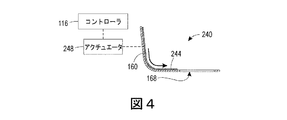
図4が、図1の押出機本体160における使用のためのシャッタシステム240の別の実施形態を示している。シャッタシステム240は、アクチュエータ248へと動作可能に接続された可撓なシャッタ本体244を備える。可撓なシャッタ本体244は、押出機本体160の底壁および側壁におおむね従う。アクチュエータ248は、スロット168の一部分を覆うべくシャッタ本体244を押出機本体160の側壁および底壁に沿って移動させるようにアクチュエータ248を動作させるように構成されたコントローラ116に動作可能に接続される。
FIG. 4 shows another embodiment of the
図4に示される実施形態は、シャッタ本体244をスロットの片側に示している。しかしながら、いくつかの実施形態においては、シャッタシステム240が、図3の実施形態と同様のやり方でスロット168の反対側の一部分を閉じるためにスロット168の他方の側においてアクチュエータ248へと動作可能に接続された第2のシャッタ本体を備えることを、読み手は理解すべきである。
In the embodiment shown in FIG. 4, the
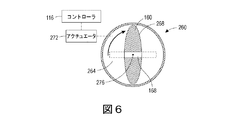
図5および図6が、図1の押出機本体160における使用のための別のシャッタシステム260を示している。シャッタシステム260は、中央開口268を定めている円形のシャッタ本体264を備える。図示の実施形態において、中央開口268は、長円形であるが、例えば矩形、台形、または三角形などの他の所望の形状が、他の実施形態において使用可能である。シャッタ本体264は、シャッタ本体を回転させるように構成されたアクチュエータ272に動作可能に接続される。アクチュエータ272は、コントローラ116に動作可能に接続され、コントローラ116は、図6に示されるようにシャッタ本体264でスロット168の少なくとも一部分を遮るために、枢支軸276を中心にしてシャッタ本体264を回転させるべくアクチュエータ272を動作させるように構成される。
5 and 6 show another
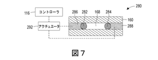
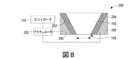
図7〜図9が、図1の押出機本体160における使用のためのシャッタシステム280の別の実施形態を示している。シャッタシステム280は、2つのシャッタ本体282、284と、2つのくさび形のコレット部材286、288とを備える。各々のくさび形のコレット部材は、アクチュエータ292に動作可能に接続される。図8および図9の縦断面図に見られるように、シャッタ本体282、284は、コレット部材286、288の斜めの表面に当接するピンである。
7-9 show another embodiment of the
アクチュエータ292は、コレット部材286、288を上下に移動させるようにアクチュエータ292を動作させるコントローラ116に動作可能に接続される。コレット部材286、288の上下移動により、コレット部材286、288の斜めの表面が対応するシャッタ本体282、284と相互作用し、シャッタ本体282、284を水平方向に移動させる。したがって、図9に示されるように、コレット部材286、288が上方に移動するとき、シャッタ本体282、284が互いに向かって移動し、スロット168の一部分を閉じる。図示の実施形態において、アクチュエータ292は、両方のコレット部材286、288へと動作可能に接続される。しかしながら、別の実施形態においては、アクチュエータ292が、コレット部材286、288のうちの一方にだけ接続され、コレット部材286、288が、一緒に上下方向に移動するように互いに接続される。
The
図10が、製作物体180を形成すべく製作材料を押し出すように三次元物体プリンタ100を動作させるために使用される一プロセス400を示している。このプロセスが何らかのタスクまたは機能を実行するという言明は、コントローラまたは汎用のプロセッサが、タスクまたは機能を実行すべくデータを操作し、システムの1つ以上の構成要素を動作させるように、コントローラまたはプロセッサへと動作可能に接続された非一時的なコンピュータにとって読み取り可能な記憶媒体に保存されたプログラムされたインストラクションを実行することを指す。上述の三次元物体プリンタ100のコントローラ116を、プロセス400を実行するコントローラまたはプロセッサをもたらすための構成要素およびプログラムされたインストラクションを備えて構成することができる。あるいは、コントローラを、本明細書に記載の1つ以上のタスクまたは機能を形成するように各々が構成された2つ以上のプロセッサならびに関連の回路および構成要素で実現することができる。
FIG. 10 shows a
図10〜図12を参照すると、プロセス400は、第1の層440(図11)のためにスロットの幅を移動方向に整列させるべく押出機本体160を回転させるようにアクチュエータ120をコントローラ116によって動作させることで始まる(ブロック404)。例えば、図11に示される実施形態において、第1の方向は、y方向である。いくつかの実施形態において、コントローラ116は、製作物体のデジタルモデルに基づいて所望の移動方向を決定する。次いで、コントローラ116は、第1の層440を形成すべく製作材料の帯442、444、446、448、450を押し出すために、スロット168から材料を押し出しつつ、押出機本体160を移動方向に平行移動させるようにアクチュエータ120を動作させる(ブロック408)。或る特定の実施形態においては、アクチュエータ120が、押し出しプロセスの最中に約5000mm/分〜8000mm/分の間の速度で押出機本体160を移動させる。別の特定の実施形態においては、アクチュエータが、押し出しプロセスの最中に約6000mm/分の速度で押出機本体160を移動させる。
Referring to FIGS. 10-12,
三次元物体プリンタのいくつかの実施形態において、コントローラ116は、帯442〜450の間の付着を改善し、したがって層の構造的な強度を改善するために、最初に中央の帯442を形成し、次いで隣の帯444、446を形成し、最後に外側の帯448、450を形成することによって帯442〜450を生成するようにアクチュエータ120および押出機アセンブリ108を動作させるように構成される。他の実施形態においては、層442〜450が、層の形成速度を高めるために、左側から右側または右側から左側へと形成される。いくつかの実施形態において、帯442〜450は、互いに異なる幅を有する。例えば、外側の帯448、450が、内側の帯442、444、446の半分の幅を有することができる。
In some embodiments of the 3D object printer, the
ひとたび第1の層440ができあがると、コントローラ116は、押出機本体160を回転させて第2の方向に整列させるようにアクチュエータ120を動作させる(ブロック412)。図示の実施形態において、第2の方向は、第1の方向に直交するx方向に合わせられる。しかしながら、第1および第2の方向の間の角度が、製作物体の特性に応じた他の所望の角度であってよいことを、読み手は理解すべきである。次いで、コントローラ116は、第2の層を形成する製作材料の帯462、464、466、468、470を押し出すために、スロット168から材料を押し出しつつ押出機本体160を平行移動させるようにアクチュエータ120を動作させる(ブロック416)。
Once the
印刷すべきさらなる層が残っている場合、コントローラ116は、押出機本体160を回転させて第3の方向に整列させるようにアクチュエータ120を動作させ、第3の方向にさらなる層を形成することができ、あるいはコントローラ116は、ブロック400の処理を繰り返して第1および第2の方向に追加の層を生成するように、アクチュエータ120を動作させることができる。図11および12は、異なる層440、460のそれぞれの帯442〜450、462〜470を明瞭に示すために、帯442〜450、462〜470を互いに離れているものとして示しているが、帯442〜450、462〜470は、典型的には、材料の連続的な層を形成するように互いに隣接して形成されることを、読み手は理解すべきである。
If additional layers remain to be printed, the
典型的には、製作物体は、図11および図12に示される単純な矩形の層ではなく、不規則な層で形成される。これらの不規則な層は、典型的には、上述の帯では形成することができない造作を含む。したがって、細部の形成が、帯においては形成することができない細部を必要とする。細部の形成は、典型的には、層の大部分を形成(ブロック408および416)する帯の押し出しの直前または直後に実行され、あるいはいくつかの場合には、最中に実行される。
Typically, the production object is formed of irregular layers rather than the simple rectangular layers shown in FIGS. 11 and 12. These irregular layers typically contain features that cannot be formed by the bands described above. Therefore, the formation of details requires details that cannot be formed in the band. The formation of details is typically performed immediately before or after the extrusion of the bands that form most of the layers (
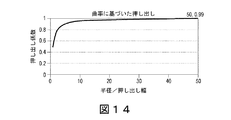
帯では形成することができない細部の一例は、曲線状の形状である。曲線状の細部を形成するために、コントローラ116は、押出機本体160を同時に回転および平行移動させる(図13)ように、アクチュエータ120を動作させるように構成され、あるいは平行移動および回転の別々のアクチュエータを有する実施形態においては、平行移動および回転の両方のアクチュエータを動作させるように構成される。押出機本体160およびスロット168が回転および平行移動するとき、スロット168の外縁が、曲線の外縁を定める一方で、スロット168の内縁が、曲線の内縁を形成する。押し出しスロット168の外縁は、押し出しスロット168の内縁よりも長い距離を移動するため、内縁および外縁の移動距離の違いを補償するために、押し出しを調節する必要がある。特には、曲線の半径がスロット168の幅と比べて比較的小さい場合、押し出される製作材料の量を、調節しなければならない。例として、スロットの幅に等しい半径(r)を有する小さな円の押し出しは、πr2に等しい面積を押し出す一方で、外縁は、2πrの直線距離を移動する。したがって、押し出しのレートは、πr2/(2πr)、すなわちr/2に比例しなければならない。他方で、きわめて大きい半径(R)の円においては、押し出しスロット168の内縁および外縁の移動距離の間の相違が、最小限であり、押し出しレートは、印刷される面積(2πrR)を経路長(2πR)で割ったもの(r、すなわちこの例ではスロット幅に等しい)に比例する。図14が、押し出しの幅またはスロット幅に対する半径の比に対してプロットした押し出し係数の曲線を示している。
An example of a detail that cannot be formed by a band is a curved shape. To form the curved details, the
いくつかの実施形態において、特定の細部は、図14〜図16に示されるように、押出機本体160を回転させて移動方向に対して斜めにすることで移動方向における押し出しされるフィラメントの有効幅480を小さくするようにアクチュエータ120をコントローラ116によって動作させることによって形成される。例えば、図16に示されるように、押し出されるリボンについて、移動方向に対して垂直な幅480は、押出機本体160が45度回転させられるときにわずかに小さくなる。図17に示されるように、押出機本体160が、スロット168の長さが移動方向に平行となるように回転させられる場合、押し出し幅480は、スロット168の最小の寸法へと小さくなる。
In some embodiments, specific details are effective in extruding filaments in the direction of movement by rotating the
上述のシャッタシステム200、220、240、260、280を有する三次元物体印刷システムの実施形態において、コントローラ216は、特定の細部を形成するためにリボンの幅を小さくすべくアクチュエータ208、232、248、272、292を動作させるように構成される。コントローラ216は、シャッタ部材がスロット168の一部分を覆い、押し出される製作材料のリボンまたはフィラメントの幅を小さくするように、アクチュエータ208、232、248、272、292を関連の1つ以上のシャッタ部材を移動させるように動作させる。小さくされた押し出し幅において、コントローラ216は、押出機本体160の平行移動、回転、あるいは平行移動および回転の両方を行い、スロット168のサイズよりも小さい製作物体の細部を形成するように、アクチュエータ120を動作させる。いくつかの実施形態において、コントローラ216は、例えば三角形または台形の細部など、細部を形成するために、平行移動/回転のアクチュエータ120およびシャッタのアクチュエータ208、232、248、272、292の両方を同時に動作させる。さらなる実施形態において、コントローラ116は、スロット168の全体を覆うことによって、押出機本体160が移動しているときに押し出しを停止させ、望ましくない押し出し(「浸出(weeping)」として知られる)を減らすように、該当のアクチュエータ208、232、248、272、292を動作させるように構成される。
In an embodiment of a three-dimensional object printing system having the
三次元物体印刷システム100の実施形態によって可能にされるこれらの技術は、スロット168を移動方向に向け、製作材料の広幅リボンを押し出すことによって、製作物体の層を迅速に形成することを可能にする。さらに、z方向において隣接する層を、互いに斜めの移動方向にて形成することで、製作物体の全体としての構造的な強度を高めることができる。さらに、スロット168による押し出しは、従来からのノズルよりも迅速な製作物体の形成を可能にする一方で、シャッタシステム200、220、240、260、280および押出機本体160の回転は、三次元物体印刷システム100がスロット式の押出機を有する公知の三次元物体プリンタでは生み出すことができない曲線および小さな細部を形成することを可能にする。
These techniques, enabled by embodiments of the 3D
図19が、上述の図1の実施形態に類似した三次元物体プリンタ600の別の実施形態を示している。簡単のために、図19の三次元物体プリンタ600と図1の三次元物体プリンタ100との間の違いだけが、本明細書において説明される。三次元物体プリンタ600においては、押出機アセンブリ608が、上述の押出機本体160に加えて、第2の押出機本体672を備える。第2の押出機本体672は、リザーバ164へと動作可能に接続され、第1の押出機本体160と同じ製作材料をリザーバ164から受け取るように構成される。第2の押出機本体は、押出機本体160の押し出しスロット168よりも小さい直径を有する押し出しノズル676を定めている。
FIG. 19 shows another embodiment of the three-
第2の押出機本体672は、押し出しスロット168を通って製作材料を押し出すことによって製作物体180上に大きな物体を生成するように第1の押出機本体160を動作させるように構成されたコントローラ116に動作可能に接続される。コントローラ116は、製作物体180上に細部およびより小さな物体を生成するために、ノズル676を通って小さなフィラメントを押し出すように第2の押出機本体672を動作させるように構成される。結果として、3D物体プリンタ600は、より大きな物体を迅速に生み出すことができるが、製作物体180上に小さな細部を生成する能力を依然として有する。
The
Claims (8)
材料の連続的なフィラメントを押し出すことを可能にするための押し出しスロットを有し、前記押し出しスロットの長さが前記押し出しスロットの幅よりも長い、押出機本体と、
前記押し出しスロットの長さと幅により形成される平面に対して平行で平らな面を有するシャッタ本体であって、前記シャッタ本体の前記面は、前記押し出しスロットの長さより長く前記押し出しスロットの幅より広い開口を有し、前記シャッタ本体の前記面の前記開口は、前記押し出しスロットの幾何学的中心を中心にして回転するように構成された、シャッタ本体と、
前記シャッタ本体へと動作可能に接続され、前記シャッタ本体を前記押し出しスロットの前記中心を中心にして、前記シャッタ本体の前記面の前記開口の前記長さが前記押し出しスロットの前記長さに平行な位置から、前記シャッタ本体の前記面の前記開口の前記長さが前記押し出しスロットの前記長さに直交し、前記押し出しスロットの第1の部分を閉じ、前記押し出しスロットを通って押し出される前記フィラメントの形状およびサイズを変更する位置へ回転するように構成されたアクチュエータと
前記押出機へと動作可能に接続され、前記押出機本体を水平面内で平行移動させるとともに、回転軸を中心にして前記押出機本体を回転させるように構成された少なくとも1つのアクチュエータと
を備える押出機アセンブリ。 Extruder assembly for 3D object printing systems
With the extruder body , which has an extrusion slot to allow the continuous filament of material to be extruded , the length of the extrusion slot being longer than the width of the extrusion slot.
A shutter body having a flat surface parallel to a plane formed by the length and width of the extrusion slot, the surface of the shutter body being longer than the length of the extrusion slot and wider than the width of the extrusion slot. A shutter body having an opening and configured such that the opening on the surface of the shutter body rotates about a geometric center of the extrusion slot.
It is operably connected to the shutter body, with the shutter body centered on the center of the extrusion slot and the length of the opening on the surface of the shutter body parallel to the length of the extrusion slot. From the position, the length of the opening on the surface of the shutter body is orthogonal to the length of the extrusion slot, the first portion of the extrusion slot is closed, and the filament extruded through the extrusion slot. An actuator configured to rotate to a position where the shape and size are changed is operably connected to the extruder, the extruder body is translated in a horizontal plane, and the extruder is centered on a rotation axis. Extruder assembly with at least one actuator configured to rotate the body.
前記押出機本体を回転させるように構成された第1のアクチュエータと、
前記押出機本体を平行移動させるように構成された第2のアクチュエータと
をさらに備える、請求項1に記載の押出機アセンブリ。 The at least one actuator
A first actuator configured to rotate the extruder body and
The extruder assembly according to claim 1, further comprising a second actuator configured to translate the extruder body.
をさらに備える、請求項1に記載の押出機アセンブリ。 The first aspect of the invention is a reservoir operably connected to the extruder body, further comprising a reservoir configured to store an amount of the material to be made and send the stored material to the extruder body. Extruder assembly described.
材料の連続的なフィラメントを押し出すことを可能にするための押し出しスロットを有している押出機本体と、
前記押出機へと動作可能に接続され、前記押出機本体を水平面内で平行移動させるように構成された少なくとも1つの第1のアクチュエータと、
斜めの表面を有するくさび形のコレットと、
少なくとも1つのシャッタ本体であって、前記押し出しスロットの長さと幅により形成される面の前記押し出しスロットの幾何学的中心を通って延びる軸に平行な鉛直軸に対して傾けられ、前記くさび形のコレットの前記斜めの表面に接触している、少なくとも1つのシャッタ本体と、
前記くさび形のコレットへと動作可能に接続された第2のアクチュエータであって、前記少なくとも1つのシャッタ本体が前記押し出しスロット横切って水平方向に移動し、前記押し出しスロットの第1の部分を閉じおよび開き、前記押し出しスロットを通って押し出されるフィラメントの幅をそれぞれ小さくおよび大きくするように、前記くさび形のコレットを前記鉛直軸に対して平行の経路に沿って移動させ、前記少なくとも1つのシャッタ本体を前記くさび形のコレットの前記斜めの表面に沿って選択的に移動させるように構成された第2のアクチュエータと
を備える押出機アセンブリ。
Extruder assembly for 3D object printing systems
With an extruder body, which has an extrusion slot to allow the continuous filament of material to be extruded,
With at least one first actuator operably connected to the extruder and configured to translate the extruder body in a horizontal plane.
A wedge-shaped collet with a slanted surface and
The wedge-shaped, at least one shutter body, tilted with respect to a vertical axis parallel to an axis extending through the geometric center of the extrusion slot on a surface formed by the length and width of the extrusion slot. With at least one shutter body in contact with the diagonal surface of the collet,
A second actuator operably connected to the wedge-shaped collet, wherein the at least one shutter body moves horizontally across the extrusion slot to close and close the first portion of the extrusion slot. The wedge-shaped collet is moved along a path parallel to the vertical axis so as to open and reduce and increase the width of the filament extruded through the extrusion slot, respectively, to move the at least one shutter body. An extruder assembly with a second actuator configured to selectively move the wedge-shaped collet along the diagonal surface.
Applications Claiming Priority (2)
| Application Number | Priority Date | Filing Date | Title |
|---|---|---|---|
| US15/147,259 | 2016-05-05 | ||
| US15/147,259 US10518471B2 (en) | 2016-05-05 | 2016-05-05 | Extruder assembly for a three-dimensional object printer |
Publications (3)
| Publication Number | Publication Date |
|---|---|
| JP2017200763A JP2017200763A (en) | 2017-11-09 |
| JP2017200763A5 JP2017200763A5 (en) | 2020-06-11 |
| JP6775464B2 true JP6775464B2 (en) | 2020-10-28 |
Family
ID=60119582
Family Applications (1)
| Application Number | Title | Priority Date | Filing Date |
|---|---|---|---|
| JP2017081696A Active JP6775464B2 (en) | 2016-05-05 | 2017-04-18 | Extruder assembly for 3D object printers |
Country Status (5)
| Country | Link |
|---|---|
| US (2) | US10518471B2 (en) |
| JP (1) | JP6775464B2 (en) |
| KR (1) | KR102182437B1 (en) |
| CN (1) | CN107344419B (en) |
| DE (1) | DE102017207291A1 (en) |
Families Citing this family (9)
| Publication number | Priority date | Publication date | Assignee | Title |
|---|---|---|---|---|
| US20170320267A1 (en) * | 2016-05-03 | 2017-11-09 | Ut-Battelle, Llc | Variable Width Deposition for Additive Manufacturing with Orientable Nozzle |
| US10933586B2 (en) * | 2017-09-13 | 2021-03-02 | Thermwood Corporation | Apparatus and method for printing large thermoplastic parts during additive manufacturing |
| CN112119501A (en) | 2018-05-18 | 2020-12-22 | 索尼半导体解决方案公司 | Image pickup element and electronic apparatus |
| CN109571954B (en) * | 2019-01-29 | 2024-03-05 | 牟振如 | Adjustable slit type extrusion head |
| JP7162145B2 (en) * | 2019-01-29 | 2022-10-27 | 振如 牟 | Extrusion head with adjustable slits and additive manufacturing system equipment equipped with the same |
| FR3096294B1 (en) * | 2019-05-21 | 2022-03-18 | Safran Helicopter Engines | Variable section three-dimensional printing process |
| US10967571B1 (en) * | 2019-10-29 | 2021-04-06 | International Business Machines Corporation | Varying orifice cross-section for three-dimensional printing |
| GB201919082D0 (en) * | 2019-12-20 | 2020-02-05 | Connect4Engineering Ltd | 3D printer head |
| ES2922048B2 (en) * | 2021-02-24 | 2023-03-06 | M Torres Disenos Ind S A Unipersonal | HEAD FOR ADDITIVE MANUFACTURING MACHINE, MACHINE AND SYSTEM INCLUDING SAID HEAD |
Family Cites Families (18)
| Publication number | Priority date | Publication date | Assignee | Title |
|---|---|---|---|---|
| FR2684590A1 (en) | 1991-12-09 | 1993-06-11 | Ciraud Pierre | Apparatus and method for the manufacture, using superposed layers, of three-dimensional objects and products manufactured by this method |
| US6030199A (en) * | 1998-02-09 | 2000-02-29 | Arizona Board Of Regents, Acting For And On Behalf Of Arizona State University | Apparatus for freeform fabrication of a three-dimensional object |
| US6113696A (en) * | 1998-05-28 | 2000-09-05 | Arizona State University | Adaptable filament deposition system and method for freeform fabrication of three-dimensional objects |
| KR100291953B1 (en) * | 1999-03-15 | 2001-06-01 | 윤덕용 | Variable deposition manufacturing method and apparatus |
| US20020020945A1 (en) | 2000-08-18 | 2002-02-21 | Uichung Cho | Forming three dimensional objects through bulk heating of layers with differential material properties |
| US7236166B2 (en) * | 2005-01-18 | 2007-06-26 | Stratasys, Inc. | High-resolution rapid manufacturing |
| DE102005056260B4 (en) | 2005-11-25 | 2008-12-18 | Prometal Rct Gmbh | Method and device for the surface application of flowable material |
| US20150151343A1 (en) * | 2012-07-30 | 2015-06-04 | Meltech Cre Limited | Continuous extrusion apparatus |
| US20140054817A1 (en) * | 2012-08-24 | 2014-02-27 | Mission Street Manufacturing, Inc. | Three-dimensional printer |
| US9403725B2 (en) * | 2013-03-12 | 2016-08-02 | University Of Southern California | Inserting inhibitor to create part boundary isolation during 3D printing |
| EP3725497A1 (en) * | 2013-03-22 | 2020-10-21 | Mark, Gregory Thomas | Three-dimensional printer |
| US9481131B2 (en) | 2013-07-18 | 2016-11-01 | Mitsubishi Electric Research Laboratories, Inc. | Method and apparatus for printing 3D objects using additive manufacturing and material extruder with translational and rotational axes |
| JP2015168135A (en) * | 2014-03-06 | 2015-09-28 | 三井化学株式会社 | Manufacturing device and manufacturing method of three-dimensional object |
| US20150290860A1 (en) | 2014-04-09 | 2015-10-15 | Leon L. Shaw | Additive manufacture via high aspect ratio nozzles |
| JP2016215581A (en) * | 2015-05-25 | 2016-12-22 | Jsr株式会社 | Apparatus and method for manufacturing three-dimensional molded object |
| CN105058789B (en) * | 2015-07-28 | 2017-09-26 | 华中科技大学 | A kind of 3D printing equipment suitable for many material workpiece |
| JP6646378B2 (en) * | 2015-08-07 | 2020-02-14 | ローランドディー.ジー.株式会社 | 3D modeling equipment |
| US10456968B2 (en) * | 2015-12-08 | 2019-10-29 | Xerox Corporation | Three-dimensional object printer with multi-nozzle extruders and dispensers for multi-nozzle extruders and printheads |
-
2016
- 2016-05-05 US US15/147,259 patent/US10518471B2/en active Active
-
2017
- 2017-04-11 KR KR1020170046470A patent/KR102182437B1/en active IP Right Grant
- 2017-04-18 JP JP2017081696A patent/JP6775464B2/en active Active
- 2017-04-18 CN CN201710251989.7A patent/CN107344419B/en active Active
- 2017-05-01 DE DE102017207291.1A patent/DE102017207291A1/en active Pending
-
2019
- 2019-11-18 US US16/686,566 patent/US11220056B2/en active Active
Also Published As
| Publication number | Publication date |
|---|---|
| KR20170125706A (en) | 2017-11-15 |
| CN107344419B (en) | 2021-10-15 |
| KR102182437B1 (en) | 2020-11-24 |
| CN107344419A (en) | 2017-11-14 |
| DE102017207291A1 (en) | 2017-11-09 |
| US20170320272A1 (en) | 2017-11-09 |
| US20200079020A1 (en) | 2020-03-12 |
| JP2017200763A (en) | 2017-11-09 |
| US10518471B2 (en) | 2019-12-31 |
| US11220056B2 (en) | 2022-01-11 |
Similar Documents
| Publication | Publication Date | Title |
|---|---|---|
| JP6775464B2 (en) | Extruder assembly for 3D object printers | |
| JP6771431B2 (en) | Methods and systems for generating 3D objects | |
| US8944802B2 (en) | Fixed printhead fused filament fabrication printer and method | |
| JP6745240B2 (en) | System and method for forming an integrated interface in a three-dimensional printed object with different build materials | |
| US10350821B2 (en) | Method and system for manufacturing a three-dimensional object by additive manufacturing | |
| US20150037446A1 (en) | Fused filament fabrication system and method | |
| KR20170104908A (en) | 3D printer | |
| JP2019502568A5 (en) | ||
| WO2018069749A1 (en) | A multiple head three dimensional printer | |
| TW201637825A (en) | Printing-height increasable three-dimensional printer | |
| JP7210641B2 (en) | Multi-nozzle extruder and method of operating multi-nozzle extruder during additive manufacturing | |
| CN109177174B (en) | 3D printing method suitable for cylindrical part | |
| WO2018122985A1 (en) | Filter and method for manufacturing same, and classifier | |
| WO2020043647A1 (en) | Method of manufacturing an object by means of 3d printing | |
| JP6688708B2 (en) | 3D object printer | |
| KR20180100875A (en) | 3D printer and production system having the same | |
| CN205291595U (en) | Three -dimensional printer | |
| KR101579140B1 (en) | Solid-based 3d printer | |
| US10471665B1 (en) | Three dimensional (3D) printing with stitching of adjacent sub-walls | |
| NL2013865B1 (en) | Apparatus for producing an object by means of additive manufacturing. | |
| EP3539774B1 (en) | Three-dimensional fabricating apparatus and three-dimensional fabricating method | |
| KR20200023685A (en) | 3D printer with independent control of multiple nozzles | |
| US20230182380A1 (en) | Defect mitigation for recoating systems for additive manufacturing | |
| TWI716703B (en) | Inkjet position adjustment method and three-dimensional printing equiment | |
| JP7446794B2 (en) | A method for manufacturing a three-dimensional object, and a three-dimensional printing device |
Legal Events
| Date | Code | Title | Description |
|---|---|---|---|
| RD02 | Notification of acceptance of power of attorney |
Free format text: JAPANESE INTERMEDIATE CODE: A7422 Effective date: 20170428 |
|
| RD04 | Notification of resignation of power of attorney |
Free format text: JAPANESE INTERMEDIATE CODE: A7424 Effective date: 20170720 |
|
| A521 | Request for written amendment filed |
Free format text: JAPANESE INTERMEDIATE CODE: A523 Effective date: 20200415 |
|
| A621 | Written request for application examination |
Free format text: JAPANESE INTERMEDIATE CODE: A621 Effective date: 20200415 |
|
| A871 | Explanation of circumstances concerning accelerated examination |
Free format text: JAPANESE INTERMEDIATE CODE: A871 Effective date: 20200415 |
|
| A975 | Report on accelerated examination |
Free format text: JAPANESE INTERMEDIATE CODE: A971005 Effective date: 20200512 |
|
| A131 | Notification of reasons for refusal |
Free format text: JAPANESE INTERMEDIATE CODE: A131 Effective date: 20200623 |
|
| A521 | Request for written amendment filed |
Free format text: JAPANESE INTERMEDIATE CODE: A523 Effective date: 20200811 |
|
| TRDD | Decision of grant or rejection written | ||
| A01 | Written decision to grant a patent or to grant a registration (utility model) |
Free format text: JAPANESE INTERMEDIATE CODE: A01 Effective date: 20200908 |
|
| A61 | First payment of annual fees (during grant procedure) |
Free format text: JAPANESE INTERMEDIATE CODE: A61 Effective date: 20201006 |
|
| R150 | Certificate of patent or registration of utility model |
Ref document number: 6775464 Country of ref document: JP Free format text: JAPANESE INTERMEDIATE CODE: R150 |
|
| R250 | Receipt of annual fees |
Free format text: JAPANESE INTERMEDIATE CODE: R250 |