JP6775285B2 - Rear side vehicle detection alarm device - Google Patents
Rear side vehicle detection alarm device Download PDFInfo
- Publication number
- JP6775285B2 JP6775285B2 JP2015186731A JP2015186731A JP6775285B2 JP 6775285 B2 JP6775285 B2 JP 6775285B2 JP 2015186731 A JP2015186731 A JP 2015186731A JP 2015186731 A JP2015186731 A JP 2015186731A JP 6775285 B2 JP6775285 B2 JP 6775285B2
- Authority
- JP
- Japan
- Prior art keywords
- vehicle
- alarm
- frames
- timing
- behind
- Prior art date
- Legal status (The legal status is an assumption and is not a legal conclusion. Google has not performed a legal analysis and makes no representation as to the accuracy of the status listed.)
- Active
Links
Images


Classifications
-
- B—PERFORMING OPERATIONS; TRANSPORTING
- B60—VEHICLES IN GENERAL
- B60Q—ARRANGEMENT OF SIGNALLING OR LIGHTING DEVICES, THE MOUNTING OR SUPPORTING THEREOF OR CIRCUITS THEREFOR, FOR VEHICLES IN GENERAL
- B60Q9/00—Arrangement or adaptation of signal devices not provided for in one of main groups B60Q1/00 - B60Q7/00, e.g. haptic signalling
-
- G—PHYSICS
- G06—COMPUTING; CALCULATING OR COUNTING
- G06V—IMAGE OR VIDEO RECOGNITION OR UNDERSTANDING
- G06V20/00—Scenes; Scene-specific elements
- G06V20/50—Context or environment of the image
- G06V20/56—Context or environment of the image exterior to a vehicle by using sensors mounted on the vehicle
- G06V20/58—Recognition of moving objects or obstacles, e.g. vehicles or pedestrians; Recognition of traffic objects, e.g. traffic signs, traffic lights or roads
Landscapes
- Engineering & Computer Science (AREA)
- Physics & Mathematics (AREA)
- General Physics & Mathematics (AREA)
- Multimedia (AREA)
- Theoretical Computer Science (AREA)
- Human Computer Interaction (AREA)
- Mechanical Engineering (AREA)
- Traffic Control Systems (AREA)
- Closed-Circuit Television Systems (AREA)
Description
本発明は、走行中の車両の後方から他の車両が接近したときに警報動作を行う後側方車両検知警報装置に関する。 The present invention relates to a rear side vehicle detection and warning device that performs an alarm operation when another vehicle approaches from behind a moving vehicle.
従来から、後方から接近してくる他の車両について自車両までの到達予測時間を算出し、この時間が所定の閾値以下のときに、ドライバへの警告を行ったり、モニタ上でこの他の車両に対してマーキングを行うようにした車両側方映像生成装置が知られている(例えば、特許文献1参照。)。具体的には、この車両側方映像生成装置では、検出した車両のうち、速度ベクトルに基づき接近している他の車両であるか否かを判定するとともに、自車両を中心とした実座標に変換した後、他の車両と自車両との距離および他の車両の速度を算出し、さらに、これらの算出した距離と速度に基づいて他の車両が自車両へ到達するまでの到達予測時間を算出している。 Conventionally, the estimated arrival time to the own vehicle is calculated for other vehicles approaching from behind, and when this time is less than a predetermined threshold value, a warning is given to the driver or the other vehicle is displayed on the monitor. There is known a vehicle side image generator in which marking is performed on a vehicle (see, for example, Patent Document 1). Specifically, this vehicle side image generator determines whether or not the detected vehicle is another vehicle approaching based on the speed vector, and sets the actual coordinates centered on the own vehicle. After the conversion, the distance between the other vehicle and the own vehicle and the speed of the other vehicle are calculated, and the estimated arrival time until the other vehicle reaches the own vehicle is calculated based on these calculated distances and speeds. It is calculated.
ところで、上述した特許文献1に開示された装置では、接近中の他の車両が自車両に到達するまでの到達予測時間が所定の閾値以下になったときに警告を出す指示を行っているため、警告を出すまでに内部処理等の時間が必要になり、実際に警告(他の車両が接近している旨の通知)を出すタイミングが遅れるという問題があった。特に、特許文献1に開示された装置では、座標変換や距離・速度算出を行った後に到達予測時間を算出しており、これらの複雑な算出に要する時間も必要になるため、警告を出す指示自体が遅れる傾向にあり、実際に警告を出すタイミングがさらに遅れることになる。
By the way, in the device disclosed in
なお、上述した例では到達予測時間が所定の閾値以下になったときに警告を出すようにしたが、例えば、自車両の後方7m以下の範囲に他の車両が進入したときに警告等をだすような場合についても同様の問題が生じる。 In the above example, a warning is issued when the estimated arrival time falls below a predetermined threshold value, but for example, a warning is issued when another vehicle enters a range of 7 m or less behind the own vehicle. A similar problem arises in such cases.
本発明は、このような点に鑑みて創作されたものであり、その目的は、自車両の後方から他の車両が接近していることを検出して警報動作を行う際の遅延を防止することができる後側方車両検知警報装置を提供することにある。 The present invention has been created in view of these points, and an object of the present invention is to prevent a delay in performing an alarm operation by detecting that another vehicle is approaching from behind the own vehicle. The purpose is to provide a rear side vehicle detection and warning device capable of being capable.
上述した課題を解決するために、本発明の後側方車両検知警報装置は、自車両の後方を所定のフレームレートで撮像する撮像手段と、撮像手段による撮像範囲に他の車両が写り込んだ後この他の車両が自車両後方の第1の位置に達するまでのフレーム数を計数するフレーム数計数手段と、フレーム数計数手段による計数によって得られたフレーム数に基づいて設定されるタイミングで、他の車両が近づいた旨を自車両の運転者に知らせる警報指示を出力する警報指示出力手段と、警報指示出力手段から警報指示が出力されたときに、運転者に所定の警報動作を行う警報手段とを備えている。 In order to solve the above-mentioned problems, the rear side vehicle detection / warning device of the present invention includes an imaging means that images the rear of the own vehicle at a predetermined frame rate, and another vehicle is reflected in the imaging range by the imaging means. After that, at the timing set based on the frame number counting means for counting the number of frames until the other vehicle reaches the first position behind the own vehicle and the number of frames obtained by counting by the frame number counting means. An alarm instruction output means that outputs an alarm instruction to notify the driver of the own vehicle that another vehicle is approaching, and an alarm that performs a predetermined alarm operation to the driver when an alarm instruction is output from the alarm instruction output means. It has the means.
他の車両が含まれるフレーム数を計数した結果に基づいて警報指示を出力するタイミングを設定しており、処理内容が単純であるため、警報動作を行う際の遅延を防止することができる。 Since the timing for outputting the alarm instruction is set based on the result of counting the number of frames including other vehicles and the processing content is simple, it is possible to prevent a delay in performing the alarm operation.
また、上述した警報指示出力手段は、フレーム数が多いときにタイミングを遅く設定し、フレーム数が少ないときにタイミングを速く設定する。これにより、実際に警報指示を出すタイミングを容易に調整することが可能となる。 Further, the alarm instruction output means described above sets the timing late when the number of frames is large, and sets the timing fast when the number of frames is small . This makes it possible to easily adjust the timing at which the alarm instruction is actually issued.
また、上述した警報指示出力手段は、第1の位置よりも自車両に近い第2の位置を他の車両が通過したときに警報手段による警報動作が行われるように、タイミングを設定することが望ましい。これにより、自車両後方の所定位置に他の車両が接近したときに確実に警報動作を行うようにすることができる。 Further, the above-mentioned alarm instruction output means can set the timing so that the alarm operation by the alarm means is performed when another vehicle passes through the second position closer to the own vehicle than the first position. desirable. As a result, it is possible to ensure that the alarm operation is performed when another vehicle approaches a predetermined position behind the own vehicle.
また、上述した警報手段は、自車両の走行車線に隣接する隣接車線を他の車両が走行中であって、この隣接車線に向けて自車両の車線変更が行われる場合に、警報動作として所定の警報音を出力することが望ましい。これにより、隣接車線において後方から接近中の他の車両が自車両後方の所定位置に接近することを予測したときであって、自車両がその隣接車線に向けて車線変更を行う際に、運転者に注意を喚起することができる。 Further, the above-mentioned warning means is predetermined as an alarm operation when another vehicle is traveling in an adjacent lane adjacent to the traveling lane of the own vehicle and the lane of the own vehicle is changed toward the adjacent lane. It is desirable to output the alarm sound of. As a result, when it is predicted that another vehicle approaching from behind in the adjacent lane will approach a predetermined position behind the own vehicle, and the own vehicle changes lanes toward the adjacent lane, the vehicle will be driven. Can call attention to a person.
また、上述した警報手段は、警報動作として、他の車両の接近を知らせる所定の表示を行うことが望ましい。これにより、自車両の後方から他の車両が接近して所定位置に到達する時点を予測して、運転者に注意を喚起することができる。 Further, it is desirable that the above-mentioned warning means perform a predetermined display for notifying the approach of another vehicle as an warning operation. As a result, it is possible to predict the time when another vehicle approaches and reaches a predetermined position from the rear of the own vehicle and call attention to the driver.
また、上述したフレーム数とこのフレーム数に対応するタイミングとの関係がテーブルの形式で予め格納されており、警報指示出力手段は、テーブルを参照することにより、フレーム数に対応するタイミングを設定することが望ましい。これにより、テーブルを参照するだけの簡単な処理によって警報指示を出すタイミングを設定することが可能となる。 Further, the relationship between the number of frames described above and the timing corresponding to the number of frames is stored in advance in the form of a table, and the alarm instruction output means sets the timing corresponding to the number of frames by referring to the table. Is desirable. This makes it possible to set the timing for issuing an alarm instruction by a simple process of referring to the table.
また、上述したフレーム数とこのフレーム数に対応するタイミングとの関係が計算式の形式で予め格納されており、警報指示出力手段は、計算式を用いて、フレーム数に対応するタイミングを設定することが望ましい。これにより、計算式に当てはめるだけの簡単な処理によって警報指示を出すタイミングを設定することが可能となる。 Further, the relationship between the above-mentioned number of frames and the timing corresponding to the number of frames is stored in advance in the form of a calculation formula, and the alarm instruction output means sets the timing corresponding to the number of frames by using the calculation formula. Is desirable. This makes it possible to set the timing for issuing an alarm instruction by a simple process that only applies to the calculation formula.
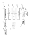
以下、本発明を適用した一実施形態の後側方車両検知警報装置について、図面を参照しながら説明する。図1は、一実施形態の後側方車両検知警報装置の構成を示す図である。図1に示すように、本実施形態の後側方車両検知警報装置1は、後方カメラ10、画像メモリ12、検出対象範囲画像抽出部14、後方車両検出部16、車両位置判定部18、フレーム数計数部20、警報指示出力部22、方向指示判定部24、警報処理部26、表示部28、スピーカ30を備えている。
Hereinafter, a rear side vehicle detection / alarm device according to an embodiment to which the present invention is applied will be described with reference to the drawings. FIG. 1 is a diagram showing a configuration of a rear side vehicle detection / alarm device according to an embodiment. As shown in FIG. 1, the rear side vehicle detection /
この後側方車両検知警報装置1は、車両に搭載されており、運転者の死角となる左右後側方の所定範囲(例えば、自車両から後方に3〜7mの範囲)が警報対象範囲として設定されており、この警報対象範囲の後方端部(自車両から後方に7mの位置)に、接近中の他の車両(後方車両)が到達したときに所定の警報動作を行う。
The rear side vehicle detection and
後方カメラ10は、車両後方に取り付けられており、自車両の走行車線や左右の隣接車線が含まれる撮像範囲を有する。例えば、CCD撮像素子やCMOS撮像素子を用いるとともに、魚眼レンズを取り付けて画角を広くしたカメラを用いることが望ましい。
The
図2は、後方カメラ10の搭載位置と撮像範囲を示す図である。また、図3は後方カメラ10による撮像によって得られた画像と、その中の左側部分画像と右側部分画像との関係を示す図である。
FIG. 2 is a diagram showing a mounting position and an imaging range of the
図2に示すように、自車両Gの後方中央、例えばナンバープレート上部に後方カメラ10が取り付けられている。この後方カメラ10は、画角Aが180度に近い角度に設定されており、その一部の角度範囲B(<A)が左側隣接車線を含む左側検出対象範囲を撮像するために用いられ、他の一部の角度範囲C(=B)が右側隣接車線を含み右側検出対象範囲を撮像するために用いられている。この後方カメラ10は、自車両後退時に車両後方の画像を車室内の表示装置に表示するためのものであり、自車両走行時にはその撮像範囲の一部が左側検出対象範囲や右側検出対象範囲に割り当てられている。
As shown in FIG. 2, the
また、図3において、長方形領域Hは後方カメラ10のフレームバッファを、一部が欠けた円形領域Cは魚眼レンズを通して撮像される自車両後方の画像をそれぞれ示している。このような画像の中で、左側の隣接車線を走行中の後方車両の位置が自車位置に対して斜め後ろとなる範囲S1が左側部分画像として抽出される。同様に、このような画像の中で、右側の隣接車線を走行中の他の車両の位置が自車位置に対して斜め後ろとなる範囲S2が右側部分画像として抽出される。
Further, in FIG. 3, the rectangular region H shows the frame buffer of the
なお、本実施形態では、1台の後方カメラ10を用いて左側検出対象範囲や右側検出対象範囲を撮像したが、自車両Gの左側面(例えば左側のドアミラー下部)に左カメラを搭載して左側検出対象範囲を撮像し、右側面(例えば右側のドアミラー下部)に右カメラを搭載して右側検出対象範囲を撮像するようにしてもよい。
In the present embodiment, the left side detection target range and the right side detection target range are imaged using one
画像メモリ12は、後方カメラ10の撮像によって得られた画像を所定のフレームレート(例えば、30フレーム/秒)でフレーム毎に格納する。
The
検出対象範囲画像抽出部14は、後方カメラ10によって撮像されて画像メモリ12に格納されたフレーム毎の画像を読み出し、この画像の中から、左側検出対象範囲に対応する左側部分画像S1と、右側検出対象範囲に対応する右側部分画像S2を抽出する。
The detection target range
後方車両検出部16は、後方カメラ10による撮像範囲に写り込んだ後方車両を検出する。この検出は、画像メモリ12に格納された各フレームの画像に含まれる左側部分画像S1と右側部分画像S2のそれぞれについて行われる。例えば、複数の車種のそれぞれに対応する前面部分の特徴が予め抽出されて登録されており、各フレームの画像にこれらの特徴を有する部分画像が含まれた場合に、その部分画像に対応する位置で後方車両が検出される。また、左側部分画像S1および右側部分画像S2に複数の後方車両が含まれている場合には、この検出は各後方車両毎に行われる。
The rear
車両位置判定部18は、後方車両検出部16によって検出された後方車両が自車両に向かって接近してきたときに、自車両から所定距離の位置(第1の位置)に到達したか否かを判定する。例えば、この第1の位置として自車両から10m後方の位置が設定されており、車両位置判定部18は、後方から接近中の他の車両が、自車位置から10m後方の位置に到達したか否かを判定する。具体的には、画像内で自車両から10m後方の位置に仮想的なラインが設定されており、後方車両の一部がこのラインを超えたときに到達した旨の判定が行われる。
The vehicle position determination unit 18 determines whether or not the rear vehicle detected by the rear
フレーム数計数部20は、後方カメラ10による撮像範囲(左側部分画像S1、右側部分画像S2)に後方車両が写り込んだ後この後方車両が自車両後方の第1の位置に達するまでのフレーム数を計数する。
The frame
図4は、フレーム数を計数する具体例を示す図であり、図4(A)には後方車両の速度が遅い場合が、図4(B)には後方車両の速度が速い場合が示されている。 FIG. 4 is a diagram showing a specific example of counting the number of frames. FIG. 4A shows a case where the speed of the rear vehicle is slow, and FIG. 4B shows a case where the speed of the rear vehicle is high. ing.
(後方車両の速度が遅い場合)
図4(A)において、F10、F11、・・・、F15は、後方カメラ10の撮像によって得られた連続した各フレームを示している。フレームF10の画像には後方車両が含まれないが、次のフレームF11には後方車両C1が含まれる。例えば、自車両の後方20m程度の位置よりも後方車両C1が近づいたときに後方車両検出部16によって後方車両が検出される。但し、後方カメラ10の解像度や設置位置に応じて、検出可能な後方車両の位置(限界値)は異なる。また、フレームF12、F13、F14と新しいフレームの画像が取得される毎に、後方車両の位置が自車両に近くなる。そして、フレームF15の画像では、後方車両の位置が自車位置後方10mの位置(この位置が点線で示されている)に到達する。フレーム計数部20は、後方車両が検出されてから自車位置後方10mの位置に到達するまでのフレーム数として、フレームF11、F12、F13、F14、F15の枚数である「5」を出力する。
(When the speed of the vehicle behind is slow)
In FIG. 4 (A), F10, F11, ..., F15 indicate consecutive frames obtained by imaging with the
(後方車両の速度が速い場合)
図4(B)において、F20、F21、F22、F23は、後方カメラ10の撮像によって得られた連続した各フレームを示している。フレームF20の画像には後方車両が含まれないが、次のフレームF21には後方車両C2が含まれる。例えば、自車両の後方20m程度の位置よりも後方車両C2が近づいたときに後方車両検出部16によって後方車両が検出される。また、フレームF22、F23と新しいフレームの画像が取得される毎に、後方車両の位置が自車両に近くなる。そして、フレームF23の画像では、後方車両の位置が自車位置後方10mの位置(この位置が点線で示されている)に到達する。フレーム計数部20は、後方車両が検出されてから自車位置後方10mの位置に到達するまでのフレーム数として、フレームF21、F22、F23の枚数である「3」を出力する。このフレーム数「3」は、上述した速度が速い場合のフレーム数「5」よりも少ない値となっている。
(When the speed of the vehicle behind is fast)
In FIG. 4B, F20, F21, F22, and F23 indicate consecutive frames obtained by imaging with the
警報指示出力部22は、フレーム数計数部20による計数によって得られたフレーム数に基づいて設定されるタイミングで、後方車両が近づいた旨を自車両の運転者に知らせる警報指示を出力する。具体的には、警報指示出力部22は、第1の位置(自車両後方10mの位置)よりも自車両に近い第2の位置(例えば自車両後方7mの位置)を、接近中の後方車両が通過したときに、警報処理部26による所定の警報動作が行われるように、警報指示を出力するタイミングを設定する。例えば、警報指示出力部22は、フレーム数が多いとき(後方車両の速度が遅いとき)に、警報指示を出力するタイミングを遅く設定し、反対に、フレーム数が少ないとき(後方車両の速度が速いとき)に、警報指示を出力するタイミングを速く設定する。
The alarm
警報指示が出力されてから警報動作を開始するまでに、内部処理等に必要な所定の時間を要するため、後方車両の速度が遅い場合には遅いタイミングで警報指示を出し、反対に後方車両の速度が速い場合には早いタイミングで警報指示を出すことにより、自車位置から後方7mの位置で速度に関係なく警報動作を開始することが可能となる。
Since it takes a predetermined time for internal processing, etc. from the output of the alarm instruction to the start of the alarm operation, if the speed of the vehicle behind is slow, the alarm instruction is issued at a late timing, and conversely, the vehicle behind When the speed is high, by issuing an alarm instruction at an early timing, it is possible to start the alarm operation at a
なお、図4に示した例では、わかりやすく説明するために、速度が遅い場合のカウント数を「5」、速い場合のカウント数を「3」としたが、毎秒30フレームで撮像が行われる場合には、実際に自車両後方の20m近傍から10mの位置に到達するまでに撮像されるフレーム数はこれらの値よりも多くなる。 In the example shown in FIG. 4, for easy understanding, the count number when the speed is slow is set to "5" and the count number when the speed is high is set to "3", but imaging is performed at 30 frames per second. In this case, the number of frames imaged from the vicinity of 20 m behind the own vehicle to the position of 10 m is larger than these values.
図5は、警報指示出力部22による警報指示の出力タイミングの設定方法を示す図である。後方車両の検出が開始された後(例えば、自車両後方の20mの位置を通過した後)から自車両の後方10mの位置に到達するまでのフレームのカウント数をNとする。また、警報指示出力部22による警報指示が出力されてから実際に警報動作が行われるまでに要する時間をTとし、自車両の後方7mの位置を後方車両が通過したタイミングでこの警報動作を開始する場合を考える。
FIG. 5 is a diagram showing a method of setting the output timing of the alarm instruction by the alarm
後方カメラ10によって毎秒30フレームの撮像が得られるものとすると、後方20mから10mまでの10mの距離の走行に要する時間T0は、
T0=N/30(sec)
となる。したがって、この後方車両の速度Vは、
V=10/T0=10/(N/30))=300/N(m/sec)
となる。この速度で、自車両後方の10mから7mまでの3mの距離の走行に要する時間T1は、
T1=3/V=3/(300/N)=N/100
となる。自車両の後方7mの位置で警報を行おうとすると、警報指示出力部22によって警報指示が出力されてから実際に警報が行われるまでの時間Tを考慮する必要があるため、自車両の後方10mの位置に後方車両が到達した時点からt秒後に警報指示を出力するものとすると、
t=T1−T=N/100−T
となる。この関係式の右辺において、Tは所定の値(固定値)であるため、フレーム数計数部20によって得られるフレーム数の計数値であるNが得られれば、警報指示を出力するタイミングtを得ることができる。警報指示出力部22は、この関係式を格納しておいて、この関係式を用いて簡単な計算を行うことにより、複雑な計算を行うことなくタイミングtを遅延なく求めることができる。
Assuming that the
T0 = N / 30 (sec)
Will be. Therefore, the speed V of this rear vehicle is
V = 10 / T0 = 10 / (N / 30)) = 300 / N (m / sec)
Will be. At this speed, the time T1 required to travel a distance of 3 m from 10 m to 7 m behind the own vehicle is
T1 = 3 / V = 3 / (300 / N) = N / 100
Will be. If an alarm is to be issued at a
t = T1-T = N / 100-T
Will be. Since T is a predetermined value (fixed value) on the right side of this relational expression, if N, which is the count value of the number of frames obtained by the frame
また、Nとtとの関係をテーブルの形成で保持しておくことにより(例えば、警報指示出力部22内あるいは外部のメモリ(図示せず)に保持する場合が考えられる)、警報指示出力部22は、計算を行うことなく、このテーブルを参照することにより、計数値Nに対応するタイミングtを取得するようにしてもよい。 Further, by holding the relationship between N and t by forming a table (for example, it may be held in a memory (not shown) inside or outside the alarm instruction output unit 22), the alarm instruction output unit The 22 may acquire the timing t corresponding to the count value N by referring to this table without performing the calculation.
方向指示判定部24は、自車両の方向指示器(ウインカー)の動作状態(作動中である否か)と、作動中の場合には指している方向(右/左)を判定する。この判定結果は警報処理部26に送られる。
The direction
警報処理部26は、警報指示出力部22から警報指示が出力されたときに、運転者に所定の警報動作を行う。具体的には、警報処理部26は、後方車両の接近を知らせる所定の表示を表示部28を用いて行う。例えば、表示部28は、運転席前方に設ける場合や、左右のドアミラーの一部を利用して取り付ける場合などが考えられる。また、警報処理部26は、自車両の走行車線に隣接する隣接車線を後方車両が走行中であって、この隣接車線に向けて自車両の車線変更が行われる場合(方向指示判定部24によって、他の車両が走行中の隣接車線に向けて方向指示器が作動中であることを判定した場合)に、スピーカ30から所定の警報音を出力する。なお、上述したように表示や音で警報する代わりに、あるいは、これらと併用して、ハンドルや座席を振動させるなどのその他の方法で警報を行うようにしてもよい。
The
上述した後方カメラ10が撮像手段に、フレーム数計数部20がフレーム数計数手段に、警報指示出力部22が警報指示出力手段に、警報処理部26、方向指示判定部24、表示部28、スピーカ30が警報手段にそれぞれ対応する。
The
本実施形態の後側方車両検知警報装置1はこのような構成を有しており、次にその動作を説明する。
The rear side vehicle detection /
図6は、後方カメラ10で自車両後方を撮像して後方車両が含まれるフレーム数を計数する動作手順を示す流れ図である。図6に示す一連の動作手順は、1フレーム分の画像が撮像される毎に繰り返される。
FIG. 6 is a flow chart showing an operation procedure in which the
後方カメラ10によって車両後方が1フレーム分撮像される(ステップ100)。得られた画像は画像メモリ12に格納される。この画像の中から検出対象範囲画像抽出部14によって左側部分画像S1と右側部分画像S2が抽出された後、後方車両検出部16は、左側部分画像S1と右側部分画像S2のそれぞれに後方車両が含まれるか否かを判定する(ステップ102)。画像内に1台も後方車両が含まれない場合には否定判断が行われ、このフレーム画像についての一連の動作が終了する。また、画像内に少なくとも1台の後方車両が含まれている場合にはステップ102の判定において肯定判断が行われる。次に、フレーム数計数部20は、検出された後方車両についてフレーム数のカウントアップ(カウント数を1増加)する(ステップ104)。複数の後方車両が検出された場合には、このカウント動作は各後方車両毎に行われる。
The
次に、車両位置判定部18は、後方車両が所定の位置(自車位置から後方に10mの位置)に到達したか否かを判定する(ステップ106)。未到達の場合(複数の後方車両が存在する場合には全ての後方車両が未到達の場合)には否定判断が行われ、このフレーム画像についての一連の動作が終了する。また、少なくとも1台の後方車両が後方から接近してきて所定の位置に到達した場合にはステップ106の判定において肯定判断が行われる。次に、警報指示出力部22は、所定位置に到達した後方車両について、ステップ104で得られたカウント値に対応する警報指示の出力タイミングを設定する(ステップ108)。
Next, the vehicle position determination unit 18 determines whether or not the rear vehicle has reached a predetermined position (a position 10 m rearward from the own vehicle position) (step 106). If it has not been reached (if there are a plurality of rear vehicles, all the rear vehicles have not been reached), a negative judgment is made, and a series of operations for this frame image is completed. Further, when at least one rear vehicle approaches from behind and reaches a predetermined position, a positive determination is made in the determination in
その後、フレーム数計数部20は、警報指示出力タイミング設定の対象となった後方車両に対応するカウント数を0にリセットする(ステップ110)。なお、複数の後方車両が同時に所定の位置に到達した場合(例えば、左右の隣接車線を走行中の2台の後方車両が同時に所定位置に到達する場合)には、上述したステップ108、110の動作がこれら複数の後方車両のそれぞれに対応して並行して行われる。このようにして、このフレーム画像についての一連の動作が終了する。
After that, the frame
図7は、後方車両が接近してきたときに運転者に向けて警報を行う動作手順を示す流れ図である。 FIG. 7 is a flow chart showing an operation procedure for issuing an alarm to the driver when a vehicle behind is approaching.
警報処理部26は、警報指示出力部22によって設定された警報指示出力タイミングが到来したか否かを判定する(ステップ200)。警報指示出力タイミングが設定されていない場合や、設定されてはいるが到来していない場合には否定判断が行われ、この判定が繰り返される。また、警報指示出力タイミングが到来した場合にはステップ200の判定において肯定判断が行われる。この場合には、後方車両の接近を表示で知らせる警報動作と、所定の条件下で警報音を出力して知らせる警報動作とが並行して行われる。
The
(表示による警報動作)
警報処理部26は、警報指示出力タイミングが到来すると、後方車両の接近を知らせる所定の表示を表示部28を用いて行う(ステップ202)。
(Alarm operation by display)
When the alarm instruction output timing arrives, the
(警報音による警報動作)
警報処理部26は、警報指示出力タイミングが到来すると、方向指示判定部24の判定結果に基づいて、ウインカー(方向指示器)が作動中であるか否かを判定する(ステップ204)。作動中でない場合には否定判断が行われ、警報音出力に関する処理は行われない。また、ウインカーが作動中の場合にはステップ204の判定において肯定判断が行われ、次に、警報処理部26は、方向指示判定部24の判定結果に基づいて、ウインカーが指し示す方向が、所定位置に後方車両が到達した側の車線を指しているか否かを判定する(ステップ206)。指していない場合には否定判断が行われ、警報音出力に関する処理は行われない。また、ウインカーが所定位置に後方車両が到達した側の車線を指している場合にはステップ206の判定において肯定判断が行われる。次に、警報処理部26は、スピーカ30から所定の警報音を出力する(ステップ208)。
(Alarm operation by alarm sound)
When the alarm instruction output timing arrives, the
なお、警報指示出力部22から警報指示が出力されてから警報音を出力する(ステップ208)までに要する時間と所定の表示を行う(ステップ202)までに要する時間とが異なる場合には、警報音の出力を優先させてタイミング設定を行うことが望ましい。また、このような場合に、警報音出力用の警報指示出力のタイミングと、表示用の警報指示出力のタイミングとを別々に設定するようにしてもよい。
If the time required from the alarm
このように、本実施形態の後側方車両検知警報装置1では、後方カメラ10によって得られたフレームの画像の中から後方車両が含まれるフレーム数を計数した結果に基づいて警報指示を出力するタイミングを設定しており、処理内容が単純であるため、警報を行う際の遅延を防止することができる。特に、計数したフレーム数が多いときに出力タイミングを遅く設定し、フレーム数が少ないときに出力タイミングを速く設定することにより、実際に警報指示を出すタイミングを容易に調整することが可能となる。
As described above, the rear side vehicle detection /
また、フレーム数の計数を終了する第1の位置よりも自車両に近い第2の位置を他の車両が通過したときに警報動作が行われるように、警報指示の出力タイミングが設定されており、自車両後方の所定位置(第2の位置)に他の後方車両が接近したときに確実に警報動作を行うようにすることができる。 In addition, the output timing of the alarm instruction is set so that the alarm operation is performed when another vehicle passes the second position closer to the own vehicle than the first position where the counting of the number of frames ends. , It is possible to ensure that the alarm operation is performed when another vehicle behind the vehicle approaches a predetermined position (second position) behind the vehicle.
また、自車両の走行車線に隣接する隣接車線を他の車両が走行中であって、この隣接車線に向けて自車両の車線変更が行われる場合に、警報動作として所定の警報音を出力することにより、自車両がその隣接車線に向けて車線変更を行う際に、運転者に注意を喚起することができる。 Further, when another vehicle is traveling in an adjacent lane adjacent to the traveling lane of the own vehicle and the lane of the own vehicle is changed toward the adjacent lane, a predetermined alarm sound is output as an alarm operation. As a result, the driver can be alerted when the own vehicle changes lanes toward the adjacent lane.
また、警報動作として後方車両の接近を知らせる所定の表示を行うことにより、自車両の後方から後方車両が接近して所定位置に到達する時点を予測して、運転者に注意を喚起することができる。 In addition, by performing a predetermined display notifying the approach of the rear vehicle as an alarm operation, it is possible to predict the time when the rear vehicle approaches from the rear of the own vehicle and reach the predetermined position, and alert the driver. it can.
また、計数によって得られたフレーム数とこのフレーム数に対応する警報指示の出力タイミングとの関係を示すテーブルを用いることにより、テーブルを参照するだけの簡単な処理によって警報指示を出すタイミングを設定することが可能となる。あるいは、計数によって得られたフレーム数とこのフレーム数に対応する警報指示の出力タイミングとの関係を示す計算式を用いることにより、計算式に当てはめるだけの簡単な処理によって警報指示を出すタイミングを設定することが可能となる。 In addition, by using a table showing the relationship between the number of frames obtained by counting and the output timing of the alarm instruction corresponding to this number of frames, the timing of issuing the alarm instruction is set by a simple process of referring to the table. It becomes possible. Alternatively, by using a calculation formula that shows the relationship between the number of frames obtained by counting and the output timing of the alarm instruction corresponding to this number of frames, the timing for issuing the alarm instruction can be set by a simple process that can be applied to the calculation formula. It becomes possible to do.
なお、本発明は上記実施形態に限定されるものではなく、本発明の要旨の範囲内において種々の変形実施が可能である。例えば、上述した実施形態では、自車両の7m後方の位置に後方車両が接近したときに、警報音出力と所定の表示を行うようにしたが、どちらか一方の動作のみを行うようにしてもよい。
The present invention is not limited to the above embodiment, and various modifications can be made within the scope of the gist of the present invention. For example, in the above-described embodiment, when the rear vehicle approaches a
また、上述した実施形態では、後方カメラ10で撮像した画像内に後方車両が含まれることを検出した時点からフレーム数のカウントを開始したが、この後方車両がさらに自車両に接近した所定の位置に到達した時点でフレーム数のカウントを開始するようにしてもよい。例えば、自車両の後方15mの位置に到達した時点でフレーム数の計数を開始し、10mの位置に到達した時点でフレーム数の計数を終了するようにしてもよい。このように、計数の開始時点を遅らせることにより、後方車両が見えるか否かがわかりづらい遠方位置において計数を開始する場合に比べて、後方車両の検出誤差に起因する計数誤差の発生を少なくすることができる。
Further, in the above-described embodiment, the number of frames is counted from the time when it is detected that the rear vehicle is included in the image captured by the
上述したように、本発明によれば、他の車両が含まれるフレーム数を計数した結果に基づいて警報指示を出力するタイミングを設定しており、処理内容が単純であるため、警報動作を行う際の遅延を防止することができる。 As described above, according to the present invention, the timing for outputting the alarm instruction is set based on the result of counting the number of frames including other vehicles, and since the processing content is simple, the alarm operation is performed. It is possible to prevent a delay at the time.
1 後側方車両検知警報装置
10 後方カメラ
12 画像メモリ
14 検出対象範囲画像抽出部
16 後方車両検出部
18 車両位置判定部
20 フレーム数計数部
22 警報指示出力部
24 方向指示判定部
26 警報処理部
28 表示部
30 スピーカ
1 Rear side vehicle detection and
Claims (6)
前記撮像手段による撮像範囲に他の車両が写り込んだ後この他の車両が自車両後方の第1の位置に達するまでのフレーム数を計数するフレーム数計数手段と、
前記フレーム数計数手段による計数によって得られたフレーム数に基づいて設定されるタイミングで、前記他の車両が近づいた旨を自車両の運転者に知らせる警報指示を出力する警報指示出力手段と、
前記警報指示出力手段から前記警報指示が出力されたときに、運転者に所定の警報動作を行う警報手段と、
を備え、前記警報指示出力手段は、前記フレーム数が多いときに前記タイミングを遅く設定し、前記フレーム数が少ないときに前記タイミングを速く設定することを特徴とする後側方車両検知警報装置。 An imaging means that captures the rear of the vehicle at a predetermined frame rate,
A frame number counting means for counting the number of frames from when another vehicle is reflected in the imaging range by the imaging means until the other vehicle reaches the first position behind the own vehicle.
An alarm instruction output means that outputs an alarm instruction to notify the driver of the own vehicle that the other vehicle is approaching at a timing set based on the number of frames obtained by counting by the frame number counting means.
When the alarm instruction is output from the alarm instruction output means, the alarm means that performs a predetermined alarm operation to the driver, and
Wherein the alarm indication output means, the set slow the timing when the number of frames is large, the next vehicle detection alarm device after characterized that you fast setting the timing when the number of frames is small ..
前記警報指示出力手段は、前記第1の位置よりも自車両に近い第2の位置を前記他の車両が通過したときに前記警報手段による警報動作が行われるように、前記タイミングを設定することを特徴とする後側方車両検知警報装置。 In claim 1 ,
The alarm instruction output means sets the timing so that the alarm operation by the alarm means is performed when the other vehicle passes through a second position closer to the own vehicle than the first position. A rear side vehicle detection and warning device characterized by.
前記警報手段は、自車両の走行車線に隣接する隣接車線を前記他の車両が走行中であって、この隣接車線に向けて自車両の車線変更が行われる場合に、前記警報動作として所定の警報音を出力することを特徴とする後側方車両検知警報装置。 In claim 1 or 2 ,
The warning means is predetermined as the warning operation when the other vehicle is traveling in an adjacent lane adjacent to the traveling lane of the own vehicle and the lane of the own vehicle is changed toward the adjacent lane. A rear side vehicle detection and warning device characterized by outputting an alarm sound.
前記警報手段は、前記警報動作として、前記他の車両の接近を知らせる所定の表示を行うことを特徴とする後側方車両検知警報装置。 In any one of claims 1 to 3 ,
The alarm means is a rear side vehicle detection / alarm device, characterized in that, as the alarm operation, a predetermined display for notifying the approach of the other vehicle is performed.
前記フレーム数とこのフレーム数に対応する前記タイミングとの関係がテーブルの形式で予め格納されており、
前記警報指示出力手段は、前記テーブルを参照することにより、前記フレーム数に対応する前記タイミングを設定することを特徴とする後側方車両検知警報装置。 In any one of claims 1 to 4 ,
The relationship between the number of frames and the timing corresponding to the number of frames is stored in advance in the form of a table.
The rear side vehicle detection / alarm device, wherein the alarm instruction output means sets the timing corresponding to the number of frames by referring to the table.
前記フレーム数とこのフレーム数に対応する前記タイミングとの関係が計算式の形式で予め格納されており、
前記警報指示出力手段は、前記計算式を用いて、前記フレーム数に対応する前記タイミングを設定することを特徴とする後側方車両検知警報装置。 In any one of claims 1 to 4 ,
The relationship between the number of frames and the timing corresponding to the number of frames is stored in advance in the form of a calculation formula.
The alarm instruction output means is a rear side vehicle detection / alarm device, characterized in that the timing corresponding to the number of frames is set by using the calculation formula.
Priority Applications (2)
| Application Number | Priority Date | Filing Date | Title |
|---|---|---|---|
| JP2015186731A JP6775285B2 (en) | 2015-09-24 | 2015-09-24 | Rear side vehicle detection alarm device |
| US15/233,430 US10589669B2 (en) | 2015-09-24 | 2016-08-10 | Following vehicle detection and alarm device |
Applications Claiming Priority (1)
| Application Number | Priority Date | Filing Date | Title |
|---|---|---|---|
| JP2015186731A JP6775285B2 (en) | 2015-09-24 | 2015-09-24 | Rear side vehicle detection alarm device |
Publications (2)
| Publication Number | Publication Date |
|---|---|
| JP2017062575A JP2017062575A (en) | 2017-03-30 |
| JP6775285B2 true JP6775285B2 (en) | 2020-10-28 |
Family
ID=58406463
Family Applications (1)
| Application Number | Title | Priority Date | Filing Date |
|---|---|---|---|
| JP2015186731A Active JP6775285B2 (en) | 2015-09-24 | 2015-09-24 | Rear side vehicle detection alarm device |
Country Status (2)
| Country | Link |
|---|---|
| US (1) | US10589669B2 (en) |
| JP (1) | JP6775285B2 (en) |
Families Citing this family (2)
| Publication number | Priority date | Publication date | Assignee | Title |
|---|---|---|---|---|
| US11493586B2 (en) * | 2020-06-28 | 2022-11-08 | T-Mobile Usa, Inc. | Mobile proximity detector for mobile electronic devices |
| CN113135193B (en) * | 2021-04-16 | 2024-02-13 | 阿波罗智联(北京)科技有限公司 | Method, device, storage medium and program product for outputting early warning information |
Family Cites Families (54)
| Publication number | Priority date | Publication date | Assignee | Title |
|---|---|---|---|---|
| US5249157A (en) * | 1990-08-22 | 1993-09-28 | Kollmorgen Corporation | Collision avoidance system |
| US5515448A (en) * | 1992-07-28 | 1996-05-07 | Yazaki Corporation | Distance measuring apparatus of a target tracking type |
| JPH06325179A (en) * | 1993-05-14 | 1994-11-25 | Nippon Telegr & Teleph Corp <Ntt> | Automatic speed measuring instrument |
| JP3134667B2 (en) * | 1994-06-02 | 2001-02-13 | 日産自動車株式会社 | Display device for vehicles |
| EP0856433B1 (en) * | 1995-10-17 | 2003-01-22 | Calsonic Corporation | Warning device for distance between cars |
| US6124647A (en) * | 1998-12-16 | 2000-09-26 | Donnelly Corporation | Information display in a rearview mirror |
| JPH11353565A (en) * | 1998-06-09 | 1999-12-24 | Yazaki Corp | Method and device for alarm of collision for vehicle |
| US20020154007A1 (en) * | 2001-04-20 | 2002-10-24 | Tsan-Lung Yang | Car reverse alerting and multi-functional display |
| JP3606223B2 (en) | 2001-04-26 | 2005-01-05 | 住友電気工業株式会社 | Vehicle side image generation method and vehicle side image generation device |
| JP2002358507A (en) * | 2001-05-31 | 2002-12-13 | Shinmaywa Engineerings Ltd | System for recording picked-up image |
| JP3738709B2 (en) * | 2001-07-13 | 2006-01-25 | 日産自動車株式会社 | Lane departure warning device |
| JP3880841B2 (en) * | 2001-11-15 | 2007-02-14 | 富士重工業株式会社 | Outside monitoring device |
| JP3747866B2 (en) * | 2002-03-05 | 2006-02-22 | 日産自動車株式会社 | Image processing apparatus for vehicle |
| JP2004086523A (en) * | 2002-08-27 | 2004-03-18 | Suzuki Motor Corp | Caution information providing device for vehicles |
| JP3922194B2 (en) * | 2003-03-11 | 2007-05-30 | 日産自動車株式会社 | Lane departure warning device |
| US7986339B2 (en) * | 2003-06-12 | 2011-07-26 | Redflex Traffic Systems Pty Ltd | Automated traffic violation monitoring and reporting system with combined video and still-image data |
| US20050278088A1 (en) * | 2004-05-29 | 2005-12-15 | Craig Thorner | Method and apparatus for collision avoidance and enhanced visibility in vehicles |
| JP4466299B2 (en) * | 2004-09-28 | 2010-05-26 | 日本電気株式会社 | Vehicle alarm device, vehicle alarm method, and vehicle alarm generation program |
| JP2007172035A (en) * | 2005-12-19 | 2007-07-05 | Fujitsu Ten Ltd | Onboard image recognition device, onboard imaging device, onboard imaging controller, warning processor, image recognition method, imaging method and imaging control method |
| CN101042802A (en) * | 2006-03-23 | 2007-09-26 | 安捷伦科技有限公司 | Traffic information sensor and method and system for traffic information detecting |
| JP4984915B2 (en) * | 2006-03-27 | 2012-07-25 | セイコーエプソン株式会社 | Imaging apparatus, imaging system, and imaging method |
| US7633383B2 (en) * | 2006-08-16 | 2009-12-15 | International Business Machines Corporation | Systems and arrangements for providing situational awareness to an operator of a vehicle |
| US8199975B2 (en) * | 2006-12-12 | 2012-06-12 | Cognex Corporation | System and method for side vision detection of obstacles for vehicles |
| CA2674830A1 (en) * | 2007-01-05 | 2008-07-17 | Nestor, Inc. | Video speed detection system |
| JP4793307B2 (en) * | 2007-04-03 | 2011-10-12 | 株式会社デンソー | Vehicle periphery monitoring device |
| EP3594853A3 (en) * | 2007-05-03 | 2020-04-08 | Sony Deutschland GmbH | Method for detecting moving objects in a blind spot region of a vehicle and blind spot detection device |
| JP2009070367A (en) * | 2007-09-13 | 2009-04-02 | Korea Electronics Telecommun | Vehicle running state warning method and unit |
| WO2009033286A1 (en) * | 2007-09-14 | 2009-03-19 | Magna International Inc. | Object detection and ranging method |
| JP4856612B2 (en) * | 2007-10-29 | 2012-01-18 | 富士重工業株式会社 | Object detection device |
| WO2009092168A1 (en) * | 2008-01-22 | 2009-07-30 | Magna International Inc. | Use of a single camera for multiple driver assistance services, park aid, hitch aid and liftgate protection |
| JP4377439B1 (en) * | 2008-06-12 | 2009-12-02 | 本田技研工業株式会社 | Vehicle periphery monitoring device |
| JP2010191793A (en) * | 2009-02-19 | 2010-09-02 | Denso It Laboratory Inc | Alarm display and alarm display method |
| JP5761910B2 (en) * | 2009-12-17 | 2015-08-12 | キヤノン株式会社 | Speed detection device |
| JP2011232293A (en) * | 2010-04-30 | 2011-11-17 | Toyota Motor Corp | Vehicle exterior sound detection device |
| US9129523B2 (en) * | 2013-05-22 | 2015-09-08 | Jaybridge Robotics, Inc. | Method and system for obstacle detection for vehicles using planar sensor data |
| US9121818B2 (en) * | 2010-07-30 | 2015-09-01 | Toyota Jidosha Kabushiki Kaisha | Movable body spectrum measuring apparatus and movable body spectrum measuring method |
| GB2483877A (en) * | 2010-09-22 | 2012-03-28 | Jonathan Keith Ross | Parking assist system |
| JP5812598B2 (en) | 2010-12-06 | 2015-11-17 | 富士通テン株式会社 | Object detection device |
| CN103548340B (en) * | 2011-05-24 | 2017-12-29 | 日产自动车株式会社 | The monitoring method of Vehicular monitoring device and vehicle |
| EP2578464B1 (en) * | 2011-10-06 | 2014-03-19 | Honda Research Institute Europe GmbH | Video-based warning system for a vehicle |
| CN202345573U (en) * | 2011-10-09 | 2012-07-25 | 陈作仁 | Automobile license plate frame for rear-end prevention and conflict alert |
| US9260122B2 (en) * | 2012-06-06 | 2016-02-16 | International Business Machines Corporation | Multisensor evidence integration and optimization in object inspection |
| JPWO2014002187A1 (en) * | 2012-06-26 | 2016-05-26 | トヨタ自動車株式会社 | Warning device for vehicle |
| KR101382873B1 (en) * | 2012-06-29 | 2014-04-08 | 엘지이노텍 주식회사 | Forward Collision Warning System and Forward Collision Warning Method |
| US8493198B1 (en) * | 2012-07-11 | 2013-07-23 | Google Inc. | Vehicle and mobile device traffic hazard warning techniques |
| US8971573B2 (en) * | 2012-09-12 | 2015-03-03 | Xerox Corporation | Video-tracking for video-based speed enforcement |
| CA2845440A1 (en) * | 2013-04-10 | 2014-10-10 | Diesel Tech Industries Ltd. | Method and system for reducing the risk of a moving machine colliding with personnel or an object |
| JP6174975B2 (en) * | 2013-11-14 | 2017-08-02 | クラリオン株式会社 | Ambient environment recognition device |
| KR101541483B1 (en) * | 2014-01-03 | 2015-08-03 | 현대모비스(주) | System for monitoring change of a traffic lane andcontrol method thereof |
| US20150228066A1 (en) * | 2014-02-10 | 2015-08-13 | Michael Scot Farb | Rear Encroaching Vehicle Monitoring And Alerting System |
| US20150329045A1 (en) * | 2014-05-15 | 2015-11-19 | Fritz B. Harris | Vehcile detection and warning system |
| TW201628887A (en) * | 2015-02-04 | 2016-08-16 | 鴻海精密工業股份有限公司 | Control system and control method for collision avoidance when opening the door |
| WO2016181618A1 (en) * | 2015-05-11 | 2016-11-17 | パナソニックIpマネジメント株式会社 | Monitored area setting device and monitored area setting method |
| US9902267B2 (en) * | 2015-05-12 | 2018-02-27 | Bendix Commercial Vehicle Systems Llc | Predicted position display for vehicle |
-
2015
- 2015-09-24 JP JP2015186731A patent/JP6775285B2/en active Active
-
2016
- 2016-08-10 US US15/233,430 patent/US10589669B2/en active Active
Also Published As
| Publication number | Publication date |
|---|---|
| JP2017062575A (en) | 2017-03-30 |
| US20170088050A1 (en) | 2017-03-30 |
| US10589669B2 (en) | 2020-03-17 |
Similar Documents
| Publication | Publication Date | Title |
|---|---|---|
| JP5704902B2 (en) | Driving support device and driving support method | |
| JP5421072B2 (en) | Approaching object detection system | |
| JP4687411B2 (en) | Vehicle peripheral image processing apparatus and program | |
| JP6278222B2 (en) | Display device for vehicle and display method for vehicle | |
| JP2010258705A (en) | Vehicle surrounding monitoring device | |
| TWI533694B (en) | Obstacle detection and display system for vehicle | |
| JP2010044561A (en) | Monitoring device to be mounted on vehicle | |
| US20100002078A1 (en) | Periphery monitoring apparatus | |
| US20150078619A1 (en) | System and method for detecting obstacles using a single camera | |
| WO2016092967A1 (en) | Image generation device and image generation method | |
| JP2006238131A (en) | Vehicle periphery monitoring apparatus | |
| JP6775285B2 (en) | Rear side vehicle detection alarm device | |
| JP6407596B2 (en) | Image processing apparatus and driving support system | |
| JP2009295018A (en) | Vehicle periphery monitoring device | |
| JP5984714B2 (en) | Three-dimensional object detection device, driving support device, and three-dimensional object detection method | |
| JP2012256159A (en) | Approaching object detecting device and method for detecting approaching object | |
| JP2009006824A (en) | Onboard unit and traveling control method | |
| US20140205147A1 (en) | Obstacle alert device | |
| JP6201809B2 (en) | Perimeter monitoring apparatus and method | |
| JP6179249B2 (en) | Vehicle detection device | |
| JP6644509B2 (en) | Vehicle detection alarm device and vehicle detection alarm method | |
| JP4598011B2 (en) | Vehicle display device | |
| TWI378873B (en) | ||
| JP2019185357A (en) | Image display device | |
| JP2016062285A (en) | Back-and-side-monitor vehicle detection and warning apparatus |
Legal Events
| Date | Code | Title | Description |
|---|---|---|---|
| A621 | Written request for application examination |
Free format text: JAPANESE INTERMEDIATE CODE: A621 Effective date: 20180308 |
|
| A977 | Report on retrieval |
Free format text: JAPANESE INTERMEDIATE CODE: A971007 Effective date: 20190130 |
|
| A131 | Notification of reasons for refusal |
Free format text: JAPANESE INTERMEDIATE CODE: A131 Effective date: 20190305 |
|
| A02 | Decision of refusal |
Free format text: JAPANESE INTERMEDIATE CODE: A02 Effective date: 20190910 |
|
| A521 | Request for written amendment filed |
Free format text: JAPANESE INTERMEDIATE CODE: A523 Effective date: 20200725 |
|
| A61 | First payment of annual fees (during grant procedure) |
Free format text: JAPANESE INTERMEDIATE CODE: A61 Effective date: 20201006 |
|
| R150 | Certificate of patent or registration of utility model |
Ref document number: 6775285 Country of ref document: JP Free format text: JAPANESE INTERMEDIATE CODE: R150 |