JP6772459B2 - Synthetic resin container - Google Patents
Synthetic resin container Download PDFInfo
- Publication number
- JP6772459B2 JP6772459B2 JP2015247621A JP2015247621A JP6772459B2 JP 6772459 B2 JP6772459 B2 JP 6772459B2 JP 2015247621 A JP2015247621 A JP 2015247621A JP 2015247621 A JP2015247621 A JP 2015247621A JP 6772459 B2 JP6772459 B2 JP 6772459B2
- Authority
- JP
- Japan
- Prior art keywords
- decompression absorption
- panel
- corner portion
- absorption panel
- container
- Prior art date
- Legal status (The legal status is an assumption and is not a legal conclusion. Google has not performed a legal analysis and makes no representation as to the accuracy of the status listed.)
- Active
Links
Images


Description
本発明は、内容物を充填、密封した後の容器内の圧力変化を吸収する減圧吸収パネルを備えた合成樹脂製容器に関する。 The present invention relates to a synthetic resin container provided with a decompression absorption panel that absorbs pressure changes in the container after the contents are filled and sealed.
従来、ポリエチレンテレフタレートなどの熱可塑性樹脂を用いて有底筒状のプリフォームを形成し、次いで、このプリフォームを二軸延伸ブロー成形などによってボトル状に成形してなる合成樹脂製の容器が、各種飲料品等を内容物とする容器として広い分野で一般的に利用されている。 Conventionally, a container made of synthetic resin, which is formed by forming a bottomed tubular preform using a thermoplastic resin such as polyethylene terephthalate and then molding this preform into a bottle shape by biaxial stretching blow molding or the like. It is generally used in a wide range of fields as a container containing various beverages and the like.
また、この種の合成樹脂製容器に内容物を充填するに際しては、加熱滅菌された内容物を高温のまま充填、密封する、いわゆるホットパックも知られている。
ホットパックにより内容物を充填、密封した後、常温に冷却された容器内は減圧状態となるため、ホットパックに供される容器にあっては、一般に、冷却に伴って容器内方に変形して当該容器の容積を減じて内圧の減少分を吸収する減圧吸収パネルが、容器胴部に周方向に沿って複数配設されている(特許文献1参照)。
Further, when filling a container made of this kind of synthetic resin with contents, a so-called hot pack is also known in which the heat-sterilized contents are filled and sealed at a high temperature.
After filling and sealing the contents with a hot pack, the inside of the container cooled to room temperature is decompressed. Therefore, the container used for the hot pack generally deforms inward as it cools. A plurality of decompression absorption panels for reducing the volume of the container and absorbing the decrease in internal pressure are arranged on the container body along the circumferential direction (see Patent Document 1).
しかしながら、この種の合成樹脂製容器においては、従前より、その軽量化や、使用樹脂量の削減による低コスト化のために、可能な限り容器を薄肉に成形する試みがなされているが、近年にあっては、このような薄肉化の要求が益々厳しくなってきている。そして、容器の薄肉化が進むほど、容器の強度を確保することが難しくなってきており、例えば、縦方向から荷重が加わると、容器胴部の周方向に隣接する減圧吸収パネルの間に形成される柱部の上下端部側において、座屈変形が生じ易い(特許文献1の段落[0044]、及び図1など参照)。 However, in this type of synthetic resin container, attempts have been made to make the container as thin as possible in order to reduce the weight and cost by reducing the amount of resin used. In that case, the demand for such thinning is becoming more and more stringent. As the thickness of the container becomes thinner, it becomes more difficult to secure the strength of the container. For example, when a load is applied from the vertical direction, it is formed between the vacuum absorbing panels adjacent to the circumferential direction of the container body. Buckling deformation is likely to occur on the upper and lower ends of the pillar portion (see paragraph [0044] of Patent Document 1, and FIG. 1 and the like).
本発明は、上記したような事情に鑑みてなされたものであり、近年、益々厳しくなってきている容器の軽量化、薄肉化の要求の下、減圧吸収パネルが形成された容器胴部の縦荷重強度が改善された合成樹脂製容器の提供を目的とする。 The present invention has been made in view of the above circumstances, and the vertical length of the container body on which the decompression absorption panel is formed is required to reduce the weight and thickness of the container, which has become more and more severe in recent years. An object of the present invention is to provide a synthetic resin container having improved load strength.
本発明に係る合成樹脂製容器は、口部、肩部、胴部、及び底部を備える合成樹脂製容器であって、前記胴部が、円筒状のパネル形成部を有し、前記パネル形成部には、前記パネル形成部の周面から陥没して段を形成する段部によって縁取られ、前記段部にパネル本体が連接された複数の減圧吸収パネルが、周方向に沿って配設されるとともに、周方向に隣接する前記減圧吸収パネルの間に柱部が形成され、前記減圧吸収パネルは、上端及び下端にコーナー部を有し、前記減圧吸収パネルの上端又は下端の少なくとも一方に位置する前記コーナー部が、当該コーナー部の始端を通る高さ方向に直交する線分上の前記減圧吸収パネルの横幅方向中央に位置する基準点から、当該コーナー部の輪郭を形成する周縁までの距離が、当該コーナー部の始端から終端に向かって徐々に長くなるように形成されており、前記減圧吸収パネルの外周側に位置し、前記減圧吸収パネルの輪郭に沿って容器外方に突出する凸状リブが、少なくとも上端又は下端に位置する前記コーナー部に設けられている構成としてある。 The synthetic resin container according to the present invention is a synthetic resin container having a mouth portion, a shoulder portion, a body portion, and a bottom portion, and the body portion has a cylindrical panel forming portion, and the panel forming portion is provided. Is bordered by a step portion that is recessed from the peripheral surface of the panel forming portion to form a step, and a plurality of decompression absorption panels in which the panel body is connected to the step portion are arranged along the circumferential direction. At the same time, a column portion is formed between the decompression absorption panels adjacent to each other in the circumferential direction, and the decompression absorption panel has corner portions at the upper end and the lower end and is located at at least one of the upper end and the lower end of the decompression absorption panel. The distance from the reference point located at the center of the decompression absorption panel in the width direction on the line segment where the corner portion is orthogonal to the height direction passing through the start end of the corner portion to the peripheral edge forming the contour of the corner portion is , It is formed so as to gradually become longer from the start end to the end of the corner portion, is located on the outer peripheral side of the decompression absorption panel, and has a convex shape protruding outward from the container along the contour of the decompression absorption panel. The ribs are provided at the corners located at least at the upper end or the lower end.
本発明によれば、容器の軽量化、薄肉化を図りながらも、十分な縦荷重強度を確保することができる。 According to the present invention, it is possible to secure sufficient vertical load strength while reducing the weight and thickness of the container.
以下、本発明の好ましい実施形態について、図面を参照しつつ説明する。 Hereinafter, preferred embodiments of the present invention will be described with reference to the drawings.
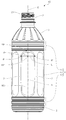
本実施形態において、容器1は、例えば、熱可塑性樹脂を使用して射出成形や圧縮成形などにより有底筒状のプリフォームを成形し、このプリフォームを二軸延伸ブロー成形などにより、図1に示すような、口部2、肩部3、胴部4、及び底部5を備えた所定の容器形状に成形することによって製造される。
In the present embodiment, for the container 1, for example, a bottomed tubular preform is formed by injection molding or compression molding using a thermoplastic resin, and this preform is formed by biaxial stretching blow molding or the like. It is manufactured by molding into a predetermined container shape having a
このような容器1を製造するにあたり、使用する熱可塑性樹脂としては、ブロー成形が可能な任意の樹脂を使用することができる。具体的には、ポリエチレンテレフタレート,ポリブチレンテレフタレート,ポリエチレンナフタレート,ポリカーボネート,ポリアリレート,ポリ乳酸又はこれらの共重合体などの熱可塑性ポリエステル,これらの樹脂あるいは他の樹脂とブレンドされたものなどが好適である。特に、ポリエチレンテレフタレートなどのエチレンテレフタレート系熱可塑性ポリエステルが、好適に使用される。また、アクリロニトリル樹脂,ポリプロピレン,プロピレン−エチレン共重合体,ポリエチレンなども使用することができる。 In manufacturing such a container 1, any resin capable of blow molding can be used as the thermoplastic resin to be used. Specifically, thermoplastic polyesters such as polyethylene terephthalate, polybutylene terephthalate, polyethylene naphthalate, polycarbonate, polyarylate, polylactic acid or copolymers thereof, and those blended with these resins or other resins are preferable. Is. In particular, ethylene terephthalate-based thermoplastic polyesters such as polyethylene terephthalate are preferably used. Further, acrylonitrile resin, polypropylene, propylene-ethylene copolymer, polyethylene and the like can also be used.
図1に示す例において、口部2には、図示しない蓋体を取り付けるためのねじ部21が形成されており、かかる口部2の下端側は、胴部4に向かって拡径する円錐台状の肩部3に連接している。
In the example shown in FIG. 1, a
また、胴部4は、容器1の高さ方向の大半を占める部位であり、円筒状のパネル形成部40には、六面の減圧吸収パネル6が周方向に沿って所定の間隔で配設されているとともに、周方向に隣接する減圧吸収パネル6の間には柱部7が形成されている。このような胴部4を備える容器1は、その横断面形状が全体的に丸みを帯びた、いわゆる丸形ボトル状の容器形状とされている。
Further, the
ここで、高さ方向とは、口部2を上にして容器1を水平面に正立させたときに、水平面に直交する方向をいうものとし、この状態で容器1の上下左右及び縦横の方向を規定するものとする。
Here, the height direction means a direction orthogonal to the horizontal plane when the container 1 is upright on the horizontal plane with the
なお、パネル形成部40は、その最外周径が高さ方向に沿って一定となるように形成されていてもよく、例えば、高さ方向中央部が膨らむように、又は窪むように、最外周径が高さ方向に沿って変化するように形成されていてもよい。
The
また、図1に示す例では、肩部3に連接する胴部4の上端側と、底部5に連接する胴部4の下端側のそれぞれに、ビード状に円環部41,42を設けて横方向(高さ方向に直交する方向)からの荷重に対する耐荷重強度を高めているが、これらの円環部41,42は適宜省略することができる。すなわち、胴部4は、周方向に沿って複数の減圧吸収パネル6が配設された円筒状のパネル形成部40を有していればよい。
Further, in the example shown in FIG. 1, bead-shaped
本実施形態において、減圧吸収パネル6は、その輪郭に沿って、パネル形成部40の円筒面状の周面から陥没して段を形成する段部60によって縁取られており、かかる段部60にパネル本体61が連接されている。
In the present embodiment, the
なお、本実施形態において、減圧吸収パネル6が、所望の減圧吸収性能を発揮できるようになっていれば、パネル本体61の具体的な形状は特に限定されない。このため、図1に示す例では、パネル本体61の具体的な形状の図示を省略している。
In the present embodiment, the specific shape of the
また、減圧吸収パネル6は、上端及び下端のコーナー部が丸められた輪郭(図示する例では、角丸長方形状の輪郭)を有している。そして、減圧吸収パネル6の横幅は、コーナー部を丸めることによって高さ方向上下に向かって縮小しおり、減圧吸収パネル6の横幅が縮小しはじめる位置をコーナー部の始端IPとし、コーナー部の丸められた区画の他方の端部を終端EPとする。
Further, the
減圧吸収パネル6のコーナー部は、当該コーナー部の始端IPを通る高さ方向に直交する線分L上の減圧吸収パネル6の横幅方向中央に位置する基準点RPから、当該コーナー部の輪郭を形成する周縁までの距離dが、当該コーナー部の始端IPから終端EPに向かって徐々に長くなるように形成されている。
The corner portion of the
周方向に沿って複数の減圧吸収パネル6が胴部4に配設された丸形ボトル状の容器1においては、容器の軽量化、薄肉化が進むにつれ、容器1に縦方向から荷重が加わると、周方向に隣接する減圧吸収パネル6の間に形成される柱部7の上下端部側の部位、すなわち、柱部7の減圧吸収パネル6のコーナー部に連接する部位に応力が集中し易く、当該部位が座屈変形の起点になってしまう傾向があった。
In the round bottle-shaped container 1 in which a plurality of
このため、本実施形態においては、上記したように、減圧吸収パネル6のコーナー部を、基準点RPから当該コーナー部の輪郭を形成する周縁までの距離dが、当該コーナー部の始端IPから終端EPに向かって徐々に長くなるように形成することで、周方向に隣接する減圧吸収パネル6の間に形成される柱部7の上下端部側における座屈変形の発生を抑制している。
Therefore, in the present embodiment, as described above, the distance d from the reference point RP to the peripheral edge forming the contour of the corner portion of the corner portion of the
なお、基準点RPからコーナー部の輪郭を形成する周縁までの距離dが、コーナー部の始端IPから終端EPに向かって徐々に長くなる態様としては、当該距離dが常に変化して徐々に長くなる態様に限らず、当該距離dが一定区間で変化せずに同じ長さとなり、次の終端EP側の区画でそれよりも長くなるというように、任意の区画ごとに徐々に長くなる態様も含まれる。すなわち、当該距離dを線分Lに対する角度θを変数とする関数F(θ)で表したときに、F(θb)−F(θa)≧0(但し、θb>θa)の関係が成り立っていればよい。 As a mode in which the distance d from the reference point RP to the peripheral edge forming the contour of the corner portion gradually increases from the start end IP of the corner portion toward the end EP, the distance d is constantly changing and gradually increases. The distance d does not change in a certain section and has the same length, and the distance d becomes longer in the next terminal EP side section. included. That is, when the distance d is represented by the function F (θ) with the angle θ with respect to the line segment L as a variable, the relationship of F (θb) −F (θa) ≧ 0 (where θb> θa) is established. Just do it.
本実施形態では、減圧吸収パネル6の横幅方向中央を通る高さ方向に沿った中心線Sと、容器1の中心軸Cとを含む平面に、減圧吸収パネル6のコーナー部の輪郭を垂直投影すると、その射影は、図2に示すような円弧状となる。かかる射影は、柱部7の当該コーナー部に連接する部位の輪郭の射影でもあり、減圧吸収パネル6のコーナー部を上記した形状にすることで、上記射影が、より大きな曲率半径Rで湾曲する円弧状となる。このようにすることで、柱部7の当該コーナー部に連接する部位への応力の集中を緩和することができ、これによって、柱部7の当該コーナー部に連接する部位を起点とする座屈変形を抑制することができる。
なお、図2には、容器1の輪郭を鎖線で示し、これに重ねて減圧吸収パネル6の輪郭の射影を太線で示すとともに、減圧吸収パネル6のコーナー部の輪郭の射影に重ねて円弧状の補助線を細線で示している。
In the present embodiment, the contour of the corner portion of the
In FIG. 2, the contour of the container 1 is shown by a chain line, the projection of the contour of the
ここで、比較のために、本実施形態における減圧吸収パネル6に代えて、基準点RPからコーナー部の輪郭をなす周縁までの距離dが、コーナー部の始端IPから終端EPに向かって徐々に短くなるようにコーナー部が形成された減圧吸収パネル6Cを配設した容器1Cの例を図6に示すとともに、このときの図2に対応する減圧吸収パネル6Cの輪郭の射影を図7に示す。このような比較例にあっては、円弧状に湾曲する上記射影の曲率半径rが、本実施形態の曲率半径Rに比べて小さく、柱部7の減圧吸収パネル6Cのコーナー部に連接する部位に応力が集中し易い傾向がみられる。
Here, for comparison, instead of the
このように、本実施形態によれば、周方向に沿って複数の減圧吸収パネル6が胴部4に配設された丸形ボトル状の容器1において、縦方向からの荷重に対し、隣接する減圧吸収パネル6の間に形成される柱部7の上下端部側への応力集中が緩和されるようにすることができ、これによって、容器1の軽量化、薄肉化を図りながらも、十分な縦荷重量強度を確保することができる。
As described above, according to the present embodiment, in the round bottle-shaped container 1 in which a plurality of
そして、このような効果が良好に奏されるように、上記したようにして減圧吸収パネル6のコーナー部を形成するにあたり、コーナー部の終端EPから、コーナー部の始端IPを通る高さ方向に直交する線分Lに下した垂線の長さLvが、コーナー部の始端IPから基準点RPまでの長さLhに対して、Lv/Lh=1.05〜4となるように、その始端IPと終端EPとを定めてコーナー部を形成するのが好ましい。
Then, in forming the corner portion of the
また、上記したようにして減圧吸収パネル6のコーナー部を形成すると、隣接する減圧吸収パネル6の間に形成される柱部7の上下端部側の横幅が広くなり、その部分の面積が大きくなる。このため、容器1を成形するに際して、柱部7の上下端部側が成形型の成形面に貼り付き易くなってしまうことが懸念される。
Further, when the corner portion of the
このような成形面への貼り付きが生じてしまうと、その離型時に、成形面に貼りついた部分には、これを引き剥がそうとする負荷がかかり、ヒケと称される歪みが発生することがある。そして、このようなヒケは、容器1が薄肉になるほど発生し易い傾向にあり、ヒケが生じてしまうと、容器1の外観が損なわれるだけでなく、強度低下を招く原因にもなる。 If such sticking to the molding surface occurs, a load trying to peel it off is applied to the portion sticking to the molding surface at the time of mold release, and a distortion called sink mark occurs. Sometimes. Then, such sink marks tend to occur as the thickness of the container 1 becomes thinner, and when the sink marks occur, not only the appearance of the container 1 is impaired but also the strength is lowered.
かかる不具合を避けるために、上記したようにして減圧吸収パネル6のコーナー部を形成するにあたっては、図3及び図4に示すように、当該コーナー部には、減圧吸収パネル6の外周側に位置し、減圧吸収パネル6の輪郭に沿って容器外方に突出する凸状リブ8を設けるのが好ましい。
なお、図4は、図3のA−A端面図であるが、図4では、容器1の肉厚を省略するとともに、当該端面に重ねてパネル形成部40の円筒面状の周面を周方向に延長した仮想線を鎖線で示している。
In order to avoid such a problem, when forming the corner portion of the
Note that FIG. 4 is an end view of AA in FIG. 3, but in FIG. 4, the wall thickness of the container 1 is omitted, and the thickness of the container 1 is omitted, and the
このようにすることで、柱部7の上下端部側が成形型の成形面に貼り付き難くしてヒケの発生を抑制し、その強度低下を防ぐことができる。さらに、このような凸状リブ8を設けることで、柱部7の上下端部側の強度を向上させることもでき、上記したようにして減圧吸収パネル6のコーナー部を形成したことと相俟って、より十分な縦荷重量強度を確保することができる。
なお、このような凸状リブ8は、図5に示すように、減圧吸収パネル6のほぼ全周にわたって設けてもよい。
By doing so, it is possible to prevent the upper and lower ends of the
As shown in FIG. 5, such a
以上、本発明について、好ましい実施形態を示して説明したが、本発明は、前述した実施形態にのみ限定されるものではなく、本発明の範囲で種々の変更実施が可能であることはいうまでもない。 Although the present invention has been described above with reference to preferred embodiments, it goes without saying that the present invention is not limited to the above-described embodiments, and various modifications can be made within the scope of the present invention. Nor.
例えば、前述した実施形態では、六面の減圧吸収パネル6を胴部4に配設した例を挙げて説明したが、これに限定されない。胴部4に配設する減圧吸収パネル6のパネル数は、四面から八面の範囲で適宜選択することができる。
For example, in the above-described embodiment, the six-sided
また、前述した実施形態では、減圧吸収パネル6の輪郭が、長方形をベースとしてそのコーナー部を丸めた角丸長方形状に形成された例を図示して説明したが、減圧吸収パネル6の輪郭のベースとなる図形は、長方形に限らず、正方形、等脚台形などであってもよい。さらに、減圧吸収パネル6は、高さ方向に沿った対称軸を有する線対称に形成するのが好ましいが、高さ方向に対して若干の傾きを有していてもよく、この場合の減圧吸収パネル6の輪郭のベースとなる図形は平行四辺形となる。
Further, in the above-described embodiment, an example in which the contour of the
また、上記したようにして減圧吸収パネル6のコーナー部を形成するにあたり、前述した実施形態で図示した例では、左右のコーナー部の終端EPが重なり、減圧吸収パネル6の上端側と下端側に直線状の部分が残っていないが、左右のコーナー部の終端EPを離間させて、減圧吸収パネル6の上端側と下端側に直線状の部分が残るようにしてもよい。一方、前述した実施形態で図示した例では、上下のコーナー部の始端IPが離間しており、減圧吸収パネル6の側辺に直線状の部分が残っているが、上下のコーナー部の始端IPが重なるようにして、減圧吸収パネル6の側辺に直線状の部分が残らないようにしてもよい。
Further, in forming the corner portion of the
また、前述した実施形態では、減圧吸収パネル6のコーナー部の全てを同じように基準点RPから当該コーナー部の輪郭を形成する周縁までの距離dが、当該コーナー部の始端IPから終端EPに向かって徐々に長くなるように形成しているが、容器1の他の部分の形状などとの兼ね合いに応じて、減圧吸収パネル6の上端又は下端の一方に位置するコーナー部についてだけ、同様に形成することもできる。
Further, in the above-described embodiment, the distance d from the reference point RP to the peripheral edge forming the contour of the corner portion is similarly changed from the start end IP of the corner portion to the end EP of all the corner portions of the
すなわち、本発明は、減圧吸収パネル6の上端及び下端にコーナー部を有し、減圧吸収パネル6の上端又は下端の少なくとも一方に位置するコーナー部が、当該コーナー部の始端IPを通る高さ方向に直交する線分L上の減圧吸収パネル6の横幅方向中央に位置する基準点RPから、当該コーナー部の輪郭を形成する周縁までの距離dが、当該コーナー部の始端IPから終端EPに向かって徐々に長くなるように形成されていれば、これ以外の細部の構成は、前述した実施形態に限定されることなく適宜変更することができる。また、前述した実施形態で説明した細部の構成を適宜取捨選択して組み合わせることもできる。
That is, the present invention has corners at the upper and lower ends of the
以上のような本発明は、内容物を充填、密封した後の容器内の圧力変化を吸収する減圧吸収パネルを備えた合成樹脂製容器に適用することができる。 The present invention as described above can be applied to a synthetic resin container provided with a decompression absorption panel that absorbs a pressure change in the container after filling and sealing the contents.
1 容器
2 口部
3 肩部
4 胴部
40 パネル形成部
5 底部
6 減圧吸収パネル
60 段部
7 柱部
8 凸状リブ
IP コーナー部の始端
EP コーナー部の終端
RP 基準点
L 始端IPを通る高さ方向に直交する線分
Lv 終端EPから線分Lに下した垂線の長さ
Lh 始端IPから基準点RPまでの長さ
d 基準点RPからコーナー部の輪郭を形成する周縁までの距離
1
Claims (3)
前記胴部が、円筒状のパネル形成部を有し、
前記パネル形成部には、前記パネル形成部の周面から陥没して段を形成する段部によって縁取られ、前記段部にパネル本体が連接された複数の減圧吸収パネルが、周方向に沿って配設されるとともに、周方向に隣接する前記減圧吸収パネルの間に柱部が形成され、
前記減圧吸収パネルは、上端及び下端にコーナー部を有し、
前記減圧吸収パネルの上端又は下端の少なくとも一方に位置する前記コーナー部が、当該コーナー部の始端を通る高さ方向に直交する線分上の前記減圧吸収パネルの横幅方向中央に位置する基準点から、当該コーナー部の輪郭を形成する周縁までの距離が、当該コーナー部の始端から終端に向かって徐々に長くなるように形成されており、
前記減圧吸収パネルの外周側に位置し、前記減圧吸収パネルの輪郭に沿って容器外方に突出する凸状リブが、少なくとも上端又は下端に位置する前記コーナー部に設けられている、
合成樹脂製容器。 A synthetic resin container having a mouth, shoulders, body, and bottom.
The body portion has a cylindrical panel forming portion and has a cylindrical panel forming portion.
The panel forming portion is bordered by a step portion that is recessed from the peripheral surface of the panel forming portion to form a step, and a plurality of decompression absorption panels in which the panel body is connected to the step portion are formed along the circumferential direction. Along with being arranged, a pillar portion is formed between the decompression absorption panels adjacent in the circumferential direction.
The decompression absorption panel has corners at the upper and lower ends.
The corner portion located at at least one of the upper end or the lower end of the decompression absorption panel is located at the center in the width direction of the decompression absorption panel on a line segment orthogonal to the height direction passing through the start end of the corner portion. , The distance to the peripheral edge forming the contour of the corner portion is formed so as to gradually increase from the start end to the end of the corner portion.
Convex ribs located on the outer peripheral side of the decompression absorption panel and projecting outward from the container along the contour of the decompression absorption panel are provided at the corners located at least at the upper end or the lower end.
Synthetic resin container.
Priority Applications (1)
| Application Number | Priority Date | Filing Date | Title |
|---|---|---|---|
| JP2015247621A JP6772459B2 (en) | 2015-12-18 | 2015-12-18 | Synthetic resin container |
Applications Claiming Priority (1)
| Application Number | Priority Date | Filing Date | Title |
|---|---|---|---|
| JP2015247621A JP6772459B2 (en) | 2015-12-18 | 2015-12-18 | Synthetic resin container |
Publications (2)
| Publication Number | Publication Date |
|---|---|
| JP2017109786A JP2017109786A (en) | 2017-06-22 |
| JP6772459B2 true JP6772459B2 (en) | 2020-10-21 |
Family
ID=59079219
Family Applications (1)
| Application Number | Title | Priority Date | Filing Date |
|---|---|---|---|
| JP2015247621A Active JP6772459B2 (en) | 2015-12-18 | 2015-12-18 | Synthetic resin container |
Country Status (1)
| Country | Link |
|---|---|
| JP (1) | JP6772459B2 (en) |
Families Citing this family (1)
| Publication number | Priority date | Publication date | Assignee | Title |
|---|---|---|---|---|
| JP7270345B2 (en) * | 2018-06-29 | 2023-05-10 | 株式会社吉野工業所 | Bottle |
-
2015
- 2015-12-18 JP JP2015247621A patent/JP6772459B2/en active Active
Also Published As
| Publication number | Publication date |
|---|---|
| JP2017109786A (en) | 2017-06-22 |
Similar Documents
| Publication | Publication Date | Title |
|---|---|---|
| JP2009154963A (en) | Resin container | |
| US11634247B2 (en) | Bottle | |
| JP4697630B2 (en) | Blow molding bottle | |
| JP5589535B2 (en) | Plastic container | |
| WO2016174831A1 (en) | Synthetic resin container | |
| JP6772459B2 (en) | Synthetic resin container | |
| WO2018008494A1 (en) | Synthetic resin container | |
| US8646636B2 (en) | Synthetic resin container | |
| JP6647759B2 (en) | Blow molded bottle made of synthetic resin | |
| JP2010036940A (en) | Plastic bottle | |
| JP6415347B2 (en) | Plastic container | |
| JP2008247430A (en) | Synthetic resin container | |
| JP2017109785A (en) | Synthetic resin container | |
| TWI658969B (en) | Synthetic resin container | |
| JP2017137118A (en) | Synthetic resin-made container | |
| US20160176604A1 (en) | Pressure reduction-absorbing bottle | |
| JP6651758B2 (en) | Synthetic resin container | |
| JP6335736B2 (en) | Bottle | |
| JP6641793B2 (en) | Synthetic resin container | |
| JP2023056965A (en) | Synthetic resin container | |
| JP6641781B2 (en) | Synthetic resin container | |
| JP7413717B2 (en) | Synthetic resin container | |
| JP7300880B2 (en) | Bottle | |
| JP6111714B2 (en) | Plastic bottle | |
| JP6638250B2 (en) | Synthetic resin container |
Legal Events
| Date | Code | Title | Description |
|---|---|---|---|
| RD01 | Notification of change of attorney |
Free format text: JAPANESE INTERMEDIATE CODE: A7421 Effective date: 20170630 |
|
| A621 | Written request for application examination |
Free format text: JAPANESE INTERMEDIATE CODE: A621 Effective date: 20181113 |
|
| A977 | Report on retrieval |
Free format text: JAPANESE INTERMEDIATE CODE: A971007 Effective date: 20190816 |
|
| A131 | Notification of reasons for refusal |
Free format text: JAPANESE INTERMEDIATE CODE: A131 Effective date: 20190827 |
|
| A521 | Written amendment |
Free format text: JAPANESE INTERMEDIATE CODE: A523 Effective date: 20191016 |
|
| A131 | Notification of reasons for refusal |
Free format text: JAPANESE INTERMEDIATE CODE: A131 Effective date: 20200121 |
|
| A521 | Written amendment |
Free format text: JAPANESE INTERMEDIATE CODE: A523 Effective date: 20200318 |
|
| TRDD | Decision of grant or rejection written | ||
| A01 | Written decision to grant a patent or to grant a registration (utility model) |
Free format text: JAPANESE INTERMEDIATE CODE: A01 Effective date: 20200901 |
|
| A61 | First payment of annual fees (during grant procedure) |
Free format text: JAPANESE INTERMEDIATE CODE: A61 Effective date: 20200914 |
|
| R150 | Certificate of patent or registration of utility model |
Ref document number: 6772459 Country of ref document: JP Free format text: JAPANESE INTERMEDIATE CODE: R150 |