JP6771908B2 - Stirring blade structure for kneading stirrer - Google Patents
Stirring blade structure for kneading stirrer Download PDFInfo
- Publication number
- JP6771908B2 JP6771908B2 JP2016049420A JP2016049420A JP6771908B2 JP 6771908 B2 JP6771908 B2 JP 6771908B2 JP 2016049420 A JP2016049420 A JP 2016049420A JP 2016049420 A JP2016049420 A JP 2016049420A JP 6771908 B2 JP6771908 B2 JP 6771908B2
- Authority
- JP
- Japan
- Prior art keywords
- stirring blade
- stirring
- axial direction
- rotating shaft
- kneading
- Prior art date
- Legal status (The legal status is an assumption and is not a legal conclusion. Google has not performed a legal analysis and makes no representation as to the accuracy of the status listed.)
- Active
Links
- 238000003756 stirring Methods 0.000 title claims description 101
- 238000004898 kneading Methods 0.000 title claims description 23
- 238000007790 scraping Methods 0.000 claims description 6
- 238000006116 polymerization reaction Methods 0.000 description 11
- 239000011347 resin Substances 0.000 description 9
- 229920005989 resin Polymers 0.000 description 9
- 230000002093 peripheral effect Effects 0.000 description 7
- 238000006068 polycondensation reaction Methods 0.000 description 4
- 238000004140 cleaning Methods 0.000 description 2
- 238000001816 cooling Methods 0.000 description 2
- 238000010438 heat treatment Methods 0.000 description 2
- 230000000717 retained effect Effects 0.000 description 2
- 238000013019 agitation Methods 0.000 description 1
- 239000012530 fluid Substances 0.000 description 1
- 238000009434 installation Methods 0.000 description 1
- 239000007788 liquid Substances 0.000 description 1
- 239000000463 material Substances 0.000 description 1
- 238000000034 method Methods 0.000 description 1
- 238000012986 modification Methods 0.000 description 1
- 230000004048 modification Effects 0.000 description 1
- 239000000843 powder Substances 0.000 description 1
Images

Landscapes
- Mixers Of The Rotary Stirring Type (AREA)
Description
この発明は、粉体、液体、高粘度流体等の混練撹拌を行う混練撹拌装置における撹拌翼構造に関するものである。 The present invention relates to a stirring blade structure in a kneading and stirring device for kneading and stirring powders, liquids, high-viscosity fluids and the like.
混練撹拌装置は、例えば、並行に配設された2本の回転軸と、その各回転軸の軸方向に取り付けられた撹拌翼(パドル)と、前記回転軸及び撹拌翼を収納するケーシングとを有する構造が一般的である。
この混練撹拌装置において、上記回転軸の回転に伴って撹拌翼の外周一部が上記ケーシングの内周面に近接してケーシング内周面をセルフクリーニングするものがある(特許文献1第1図〜第11図等参照)。
The kneading and stirring device includes, for example, two rotating shafts arranged in parallel, a stirring blade (paddle) attached in the axial direction of each rotating shaft, and a casing for accommodating the rotating shaft and the stirring blade. The structure to have is common.
In this kneading and stirring device, there is a device in which a part of the outer periphery of the stirring blade is close to the inner peripheral surface of the casing and the inner peripheral surface of the casing is self-cleaned as the rotating shaft rotates (Patent Document 1, FIGS. 1 to 1 to 1). See FIG. 11 and the like).
このセルフクリーニング型混練撹拌装置には、被処理物として重合度の低い重縮合系樹脂が供給され、その樹脂を撹拌して重合度を高めるものがあり、被処理物の供給とその排出を連続的に行う連続式と、一定量の被処理物を混練撹拌装置内に供給して混練撹拌するバッチ式がある。前者は、コンパクトで、高い生産性を得ることができるが、十分な滞留時間を得にくく、所要の重合度を得ることができない問題がある。後者は、十分な重合度を得ることができるが、前者に対し生産性が劣り、その一回の供給量によって処理量が決定されるため、生産性を高めるには、大型化(大容量化)する必要がある。その大型化は広い設置スペースが必要な上に、その装置も高価なものとなる。 In this self-cleaning type kneading and stirring device, a polycondensation resin having a low degree of polymerization is supplied as an object to be treated, and the resin is agitated to increase the degree of polymerization, and the object to be processed is continuously supplied and discharged. There is a continuous type in which a certain amount of object to be processed is supplied into a kneading and stirring device to knead and stir. The former is compact and can obtain high productivity, but has a problem that it is difficult to obtain a sufficient residence time and a required degree of polymerization cannot be obtained. The latter can obtain a sufficient degree of polymerization, but the productivity is inferior to that of the former, and the processing amount is determined by the amount of one supply. Therefore, in order to increase the productivity, the size is increased (capacity is increased). )There is a need to. The increase in size requires a large installation space, and the equipment is also expensive.
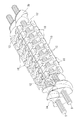
以上から、連続式のセルフクリーニング型混練撹拌装置が多く製造されているが、この混練撹拌装置は、通常、本願に係る図1を参照して説明すると、同径の2つの円が交差する断面形状を有する筒状ケーシング1の内部の処理室2に、両端にスクリュウ羽根3a、3bが、その両スクリュウ羽根3a、3bの間に軸方向に沿って多数の撹拌翼(パドル)10が設けられた2本の回転軸5が互いに平行に配された構成である。また、前記ケーシング1は、一端側上部に供給口6が、他端側下部に排出口7がそれぞれ設けられ、その供給口6と排出口7を除く外周面に加熱・冷却用のジャケット8が設けられている。
From the above, many continuous self-cleaning type kneading and stirring devices are manufactured, but this kneading and stirring device is usually described with reference to FIG. 1 according to the present application, and has a cross section in which two circles having the same diameter intersect. In the
上記両回転軸5は、それぞれの両端部をケーシング1から突出させており、モータによって両回転軸5、5が回転すると、ケーシング1の供給口6から処理室2に供給された重縮合系樹脂(被処理物)cは、スクリュウ羽根3aによって撹拌翼10に送り込まれるとともに、スクリュウ羽根3bによって撹拌翼10に送り戻され、その撹拌翼10によって混練撹拌されながらケーシング1の他端側へ徐々に移行して重合度の高くなった樹脂c’となって排出口7から排出される。
Both ends of both rotating
このような混練撹拌装置において、ケーシング1内に、被処理物cを適切な時間、滞留撹拌させるかが問題となる。このとき、いたずらに滞留させていては、生産性が低下するとともに重合度に問題が生じる場合があり、送り用スクリュウ羽根3aのみでは被処理物cを適切に送ることは困難である。
このため、従来から種々の技術が考えられており、例えば、撹拌翼10をスパイラル状に傾斜させて回転軸5に取り付けたり、撹拌翼10の外周端側面を傾斜させたりしたものがある(特許文献1第4〜図9参照)。
しかし、撹拌翼10をスパイラル状に傾斜させた構造は、排出口7への送り作用しか行わず、滞留時間の調整が困難な問題がある。また、撹拌翼10の外周端側面を傾斜させた構造は、外周端傾斜面は狭く撹拌翼10の厚み方向のため、十分な広さを確保出来ず、適切な送り速度や送り量を設定できない問題がある。
In such a kneading and stirring device, it is a problem whether the object to be processed c is retained and stirred in the casing 1 for an appropriate time. At this time, if the material is retained unnecessarily, the productivity may decrease and the degree of polymerization may be problematic, and it is difficult to properly feed the object to be treated c only with the
For this reason, various techniques have been conventionally considered. For example, the stirring
However, the structure in which the
この発明は、以上の実状の下、撹拌翼の形状を工夫することによって上記適切な送り速度や送り量を設定できるようにすることを課題とする。 An object of the present invention is to make it possible to set the appropriate feed rate and feed amount by devising the shape of the stirring blade under the above conditions.
上記課題を達成するため、この発明は、撹拌翼を切り欠くことによって被処理物送り方向に傾斜する斜面を形成することとしたのである。
その切欠き個所を適宜に選択すれば、適切な送り量を確保できて適切な撹拌を行うことができる。
In order to achieve the above object, the present invention has decided to form a slope inclined in the object feeding direction by cutting out the stirring blade.
If the notch portion is appropriately selected, an appropriate feed amount can be secured and appropriate stirring can be performed.
この発明の一構成としては、筒状ケーシング内にその筒軸方向の回転軸を設け、前記回転軸にその軸方向に順々に板状撹拌翼を回転軸の直交方向に取り付けた撹拌翼構造であって、前記撹拌翼の前記軸方向表面に切欠きによって被処理物送り方向に傾斜する傾斜面が形成されている構成を採用することができる。 One configuration of the present invention is a stirring blade structure in which a rotating shaft in the tubular axial direction is provided in a tubular casing, and plate-shaped stirring blades are sequentially attached to the rotating shaft in the axial direction in the direction orthogonal to the rotating shaft. Therefore, it is possible to adopt a configuration in which an inclined surface inclined in the processing object feeding direction is formed on the axial surface of the stirring blade by a notch.
この発明の他の構成としては、筒状ケーシング内にその筒軸方向の回転軸を設け、前記回転軸にその軸方向に順々に板状撹拌翼を回転軸の直交方向に取り付けた撹拌翼構造であって、前記各撹拌翼は三角形状をして、その三角形状の各辺部分が切り欠かれて、その切欠き部の切り欠き端面によって被処理物送り方向に傾斜する傾斜面が形成されている構成を採用することができる。 As another configuration of the present invention, a stirring blade in which a rotating shaft in the tubular axis direction is provided in the tubular casing, and plate-shaped stirring blades are sequentially attached to the rotating shaft in the axial direction in the direction orthogonal to the rotating shaft. In the structure, each stirring blade has a triangular shape, each side portion of the triangular shape is cut out, and an inclined surface inclined in the processing object feeding direction is formed by the cutout end surface of the cutout portion. It is possible to adopt the configured configuration.
この発明のさらに他の構成としては、筒状ケーシング内にその筒軸方向の回転軸を設け、前記回転軸にその軸方向に順々に板状撹拌翼を回転軸の直交方向に取り付けた撹拌翼構造であって、前記各撹拌翼は三角形状をして、その三角形の頂点の側面に、その側面から回転軸の軸方向に突出する掻上部材を有し、その掻上部材の前記軸方向表面に切欠きによって被処理物送り方向に傾斜する傾斜面が形成されている構成を採用することができる。 As still another configuration of the present invention, stirring is provided in a tubular casing in the direction of the tubular axis, and plate-shaped stirring blades are sequentially attached to the rotating shaft in the axial direction in the direction orthogonal to the axis of rotation. In the blade structure, each stirring blade has a triangular shape, and has a scraping member protruding from the side surface in the axial direction of the rotation axis on the side surface of the apex of the triangle, and the shaft of the scraping member. It is possible to adopt a configuration in which an inclined surface inclined in the processing object feeding direction is formed on the directional surface by a notch.
上記各構成は相互に採用することができる。例えば、上記さらに他の構成において 上記撹拌翼の上記軸方向表面に切欠きによって被処理物送り方向に傾斜する傾斜面が形成されていたり、前記撹拌翼の三角形状の各辺部分が切り欠かれて、その切欠き部の切り欠き端面によって被処理物送り方向に傾斜する傾斜面が形成されていたりする構成とすることができる。 The above configurations can be mutually adopted. For example, in the other configuration, an inclined surface inclined in the feed direction of the object to be processed is formed by a notch on the axial surface of the stirring blade, or each triangular side portion of the stirring blade is cut out. Therefore, the cutout end face of the cutout portion may form an inclined surface that is inclined in the feed direction of the object to be processed.
この発明は、以上のように構成したので、被処理物の送り用傾斜面の設計自由度が高いため、適切な送り速度(滞留時間)の混練撹拌装置を得ることができる。 Since the present invention is configured as described above, the degree of freedom in designing the inclined surface for feeding the object to be processed is high, so that a kneading and stirring device having an appropriate feeding speed (residence time) can be obtained.
この発明に係る混練撹拌装置(ニーダ)の第1の実施形態を図1〜図3に示し、この実施形態の混練撹拌装置は、被処理物として重合度の低い重縮合系樹脂cが供給され、供給された樹脂(被処理物)cを撹拌して重合度を高める重合装置として用いられるものであり、同径の2つの円が交差する断面形状を有する筒状ケーシング1の内部の処理室2に、両端にスクリュウ羽根3a、3bが、その両スクリュウ羽根3a、3bの間に軸方向に沿って多数の撹拌翼(パドル)10が設けられた、ケーシング1の筒軸方向の2本の回転軸5が互いに平行に配されている。各撹拌翼10は板状をして回転軸5に直交している。
上記ケーシング1は、一端側上部に供給口6が、他端側下部に排出口7がそれぞれ設けられ、その供給口6と排出口7を除く外周面に加熱・冷却用のジャケット8が設けられている。
The first embodiment of the kneading and stirring device (kneader) according to the present invention is shown in FIGS. 1 to 3, and the kneading and stirring device of this embodiment is supplied with a polycondensation resin c having a low degree of polymerization as an object to be treated. , It is used as a polymerization apparatus that stirs the supplied resin (object to be treated) c to increase the degree of polymerization, and has a processing chamber inside a tubular casing 1 having a cross-sectional shape in which two circles having the same diameter intersect. Two
The casing 1 is provided with a supply port 6 at the upper end on one end side and a
上記両回転軸5は、それぞれの両端部をケーシング1から突出させて、その一方の突出端部に図示省略したモータが連結されており、そのモータによって両回転軸5、5は同一方向に同一回転速度で回転する。また、各スクリュウ羽根3a、3bはその中心の取付孔(図示省略)から回転軸5に挿し通してキー止めして回転軸5に直交して取り付けられており、その供給口6側のスクリュウ羽根3aは送り羽根であり、排出口7側のスクリュウ羽根3bは戻し羽根である。
このため、回転軸5が回転駆動することにより、ケーシング1の供給口6から処理室2に供給された重縮合系樹脂(被処理物)cは、スクリュウ羽根3aによって撹拌翼10に送り込まれるとともに、スクリュウ羽根3bによって撹拌翼10に送り戻され、その撹拌翼10によって混練撹拌されながらケーシング1の他端側へ徐々に移行して重合度の高くなった樹脂c’となって排出口7から排出される。
Both rotating
Therefore, the polycondensation resin (object to be processed) c supplied from the supply port 6 of the casing 1 to the
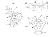
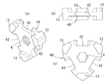
上記各撹拌翼10は、各回転軸5、5のそれぞれの軸方向に交互位置で順々に固定されており、各回転軸5の軸方向に沿って同一位相となっている。この位相を、例えば、60度等と異ならせることができる。これらの撹拌翼10は、例えばSUS316等からなり、図3に示すように、ルーローの三角形状板片(図4参照)11の各3辺を適宜に欠如したほぼ正三角形状を呈しており、その中心に回転軸5への取付孔4が形成されている。そのルーローの径は、適宜に設定すれば良いが、例えば、118mmとする。
その欠如した各辺の両側面は、切り込みによって軸心の周方向及び径方向の傾斜面12となっている。すなわち、その傾斜面12は、図3(c)において、a矢印方向に徐々に深くなっているとともに、b矢印方向において、徐々に深くなっており、その傾きは被処理物cを送り出す作用を発揮する。
この撹拌翼10の各頂点には両側に突出する撹拌突起(掻上部材)13が形成されており、この突起(部材)13によって被処理物cの撹拌が促進される。
The stirring
Both side surfaces of the lacking side are
Stirring protrusions (raising members) 13 projecting on both sides are formed at each apex of the
この構成の撹拌翼10を有する図1に示す混練撹拌装置において、その撹拌翼10が図3(c)の矢印方向に回転すると、上記傾斜面12(図3(b)において、下側)によって、回転軸5の軸方向及び径方向(送り出し方向)の力が被処理物cに付与されて撹拌される。また、撹拌突起13によっても撹拌される。
このため、傾斜面12のa、b方向の傾斜角度や撹拌突起13の大きさ・側方への突出量等を適宜に設定することによって、被処理物cの送り量を適宜に設定して供給口6から排出口7に適切な滞留時間でもって適切な撹拌がなされ、適切な重合がなされた被処理物c’が移動する。
なお、図3(b)において、板片11の両側(上下側)に切り込みによってそれぞれ傾斜面12、12を形成しているが、このような構成とすることによって、この撹拌翼10は、図3に示すように左右(両側)対称となり、すなわち、回転軸5に直交する厚み方向の中心を通る線に対して左右回転対称となり、この撹拌翼10をその左右側面を考慮せずに回転軸5に取付け得る。
In the kneading and stirring device shown in FIG. 1 having the stirring
Therefore, the feed amount of the object to be processed c is appropriately set by appropriately setting the inclination angle of the
In addition, in FIG. 3B, inclined surfaces 12 and 12 are formed by notches on both sides (upper and lower sides) of the
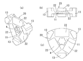
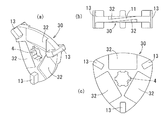
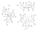
上記実施形態において、ルーローの三角形状板片11の各3辺を欠如していない態様が図4に示す撹拌翼20であり(送り傾斜面22)、さらに、撹拌突起13の形状を異ならせた撹拌翼30(送り傾斜面32)を図5に示す。
図6、図7には、ルーローの三角形状板片11の各3辺一部を欠如しているが、傾斜面をその欠如部の側面に形成したり(図6)、撹拌突起13に形成したりした撹拌翼40、50を示す(送り傾斜面42、52)。
このように、傾斜面12、22、32、42、52の形成位置は適宜に設定することができるため、撹拌度合いを考慮してそれらの傾斜面12、22、32、42、52の形成位置や傾斜角度、及び撹拌突起13の形状も撹拌度合い等を考慮して適宜に設定する。すなわち、例えば、図6、図7の実施形態においても、図3〜図5で示す、板片11の側面の傾斜面12、22、32を形成することもできる。図3〜図6に示す各実施形態においては、各突起(掻上部材)13及び各傾斜面12、22、32、42はそれぞれ3個設けられて回転軸5の周りに120度の間隔回転位置となっている。
したがって、今回開示された実施の形態はすべての点で例示であって制限的なものではないと考えられるべきである。この発明の範囲は、特許請求の範囲によって示され、特許請求の範囲と均等の意味および範囲内でのすべての変更が含まれることが意図される。
In the above embodiment, the stirring
In FIGS. 6 and 7, a part of each of the three sides of the Reuleaux
As described above, since the forming positions of the
Therefore, the embodiments disclosed this time should be considered to be exemplary in all respects and not restrictive. The scope of the present invention is indicated by the scope of claims and is intended to include all modifications within the meaning and scope equivalent to the scope of claims.
1 ケーシング
2 処理室
3a、3b スクリュウ羽根
5 回転軸
6 供給口
7 排出口
10、20、30、40、50 撹拌翼
12、22、32、42、52 傾斜面
13 撹拌突起
c、c’ 被処理物(樹脂)
1
Claims (4)
Priority Applications (1)
| Application Number | Priority Date | Filing Date | Title |
|---|---|---|---|
| JP2016049420A JP6771908B2 (en) | 2016-03-14 | 2016-03-14 | Stirring blade structure for kneading stirrer |
Applications Claiming Priority (1)
| Application Number | Priority Date | Filing Date | Title |
|---|---|---|---|
| JP2016049420A JP6771908B2 (en) | 2016-03-14 | 2016-03-14 | Stirring blade structure for kneading stirrer |
Related Child Applications (1)
| Application Number | Title | Priority Date | Filing Date |
|---|---|---|---|
| JP2019049743A Division JP6870018B2 (en) | 2019-03-18 | 2019-03-18 | Stirring blade structure for kneading stirrer |
Publications (2)
| Publication Number | Publication Date |
|---|---|
| JP2017164659A JP2017164659A (en) | 2017-09-21 |
| JP6771908B2 true JP6771908B2 (en) | 2020-10-21 |
Family
ID=59909553
Family Applications (1)
| Application Number | Title | Priority Date | Filing Date |
|---|---|---|---|
| JP2016049420A Active JP6771908B2 (en) | 2016-03-14 | 2016-03-14 | Stirring blade structure for kneading stirrer |
Country Status (1)
| Country | Link |
|---|---|
| JP (1) | JP6771908B2 (en) |
Families Citing this family (6)
| Publication number | Priority date | Publication date | Assignee | Title |
|---|---|---|---|---|
| KR101896937B1 (en) * | 2016-08-24 | 2018-09-10 | 지에스칼텍스 주식회사 | Kneader reactor |
| JP6870018B2 (en) * | 2019-03-18 | 2021-05-12 | 株式会社栗本鐵工所 | Stirring blade structure for kneading stirrer |
| JP7629297B2 (en) * | 2020-12-11 | 2025-02-13 | 株式会社北川鉄工所 | Twin screw mixer and mixing method of mixed materials |
| JP2022188507A (en) * | 2021-06-09 | 2022-12-21 | 株式会社栗本鐵工所 | Kneading stirrer |
| JP7402200B2 (en) * | 2021-06-24 | 2023-12-20 | 株式会社栗本鐵工所 | Kneading stirring device |
| CN114699970B (en) * | 2022-03-22 | 2025-10-17 | 武汉科技大学 | Lu Luoke-shaped triangular baffle structure passive micromixer |
Family Cites Families (8)
| Publication number | Priority date | Publication date | Assignee | Title |
|---|---|---|---|---|
| FR1119651A (en) * | 1949-07-15 | 1956-06-22 | Homogenizer device for machine for extruding or injecting thermoplastic materials | |
| JPS63110539U (en) * | 1987-01-12 | 1988-07-15 | ||
| JP2925599B2 (en) * | 1989-11-02 | 1999-07-28 | 住友重機械工業株式会社 | High viscosity liquid processing equipment |
| JP3115182B2 (en) * | 1993-07-29 | 2000-12-04 | 日立造船株式会社 | Kneading extruder for ash solidification |
| JP3197179B2 (en) * | 1995-01-31 | 2001-08-13 | 三菱重工業株式会社 | Stirrer |
| US20040145964A1 (en) * | 2001-04-25 | 2004-07-29 | Alfred Kunz | Mixer bars cleaning in a radial or axial manner |
| US20050219939A1 (en) * | 2004-04-05 | 2005-10-06 | Mcneilus Truck And Manufacturing, Inc. | Concrete batching pre-mixer and method |
| DE102012106872A1 (en) * | 2012-01-05 | 2013-07-11 | List Holding Ag | Device for carrying out mechanical, chemical and / or thermal processes |
-
2016
- 2016-03-14 JP JP2016049420A patent/JP6771908B2/en active Active
Also Published As
| Publication number | Publication date |
|---|---|
| JP2017164659A (en) | 2017-09-21 |
Similar Documents
| Publication | Publication Date | Title |
|---|---|---|
| JP6771908B2 (en) | Stirring blade structure for kneading stirrer | |
| EP3031519B1 (en) | Stirrer | |
| WO2017002905A1 (en) | Stirring device | |
| CN111655440B (en) | Asymmetric three-blade spiral shaft for mixing kneader | |
| US8087815B2 (en) | Kneader | |
| CN109310961B (en) | Stirring blade and stirring device | |
| JP2019104008A (en) | Agitator | |
| JP6870018B2 (en) | Stirring blade structure for kneading stirrer | |
| CN1309462C (en) | Dynamic mixer | |
| EP2732870A1 (en) | Kneading and stirring device | |
| JP2020044536A (en) | Stirring blade structure for kneading stirrer | |
| JP2016028799A (en) | Kneading and stirring device | |
| JP6726003B2 (en) | Slurry kneading/dispersing device | |
| WO2007037263A1 (en) | Agitator | |
| JP5175822B2 (en) | Kneading equipment | |
| JP6087135B2 (en) | Kneading equipment | |
| JP2016028798A (en) | Kneading and stirring device | |
| CN103429408B (en) | Continuous mixer | |
| JP7702725B2 (en) | In-line Dispersion Device | |
| JP2012192560A (en) | Biaxial extruder | |
| JP2023003558A (en) | Mixing agitating device | |
| JP2016028797A (en) | Kneading and stirring device | |
| JP3203174B2 (en) | High viscosity liquid processing and high speed liquid processing equipment | |
| JP2024148632A (en) | Continuous Mixing Equipment | |
| JP2013085974A (en) | Processing device |
Legal Events
| Date | Code | Title | Description |
|---|---|---|---|
| A621 | Written request for application examination |
Free format text: JAPANESE INTERMEDIATE CODE: A621 Effective date: 20171110 |
|
| A977 | Report on retrieval |
Free format text: JAPANESE INTERMEDIATE CODE: A971007 Effective date: 20180625 |
|
| A131 | Notification of reasons for refusal |
Free format text: JAPANESE INTERMEDIATE CODE: A131 Effective date: 20180703 |
|
| A521 | Request for written amendment filed |
Free format text: JAPANESE INTERMEDIATE CODE: A523 Effective date: 20180829 |
|
| A02 | Decision of refusal |
Free format text: JAPANESE INTERMEDIATE CODE: A02 Effective date: 20181218 |
|
| A521 | Request for written amendment filed |
Free format text: JAPANESE INTERMEDIATE CODE: A523 Effective date: 20190318 |
|
| C60 | Trial request (containing other claim documents, opposition documents) |
Free format text: JAPANESE INTERMEDIATE CODE: C60 Effective date: 20190318 |
|
| A911 | Transfer to examiner for re-examination before appeal (zenchi) |
Free format text: JAPANESE INTERMEDIATE CODE: A911 Effective date: 20190326 |
|
| C21 | Notice of transfer of a case for reconsideration by examiners before appeal proceedings |
Free format text: JAPANESE INTERMEDIATE CODE: C21 Effective date: 20190409 |
|
| A912 | Re-examination (zenchi) completed and case transferred to appeal board |
Free format text: JAPANESE INTERMEDIATE CODE: A912 Effective date: 20190531 |
|
| C211 | Notice of termination of reconsideration by examiners before appeal proceedings |
Free format text: JAPANESE INTERMEDIATE CODE: C211 Effective date: 20190604 |
|
| C22 | Notice of designation (change) of administrative judge |
Free format text: JAPANESE INTERMEDIATE CODE: C22 Effective date: 20200303 |
|
| C22 | Notice of designation (change) of administrative judge |
Free format text: JAPANESE INTERMEDIATE CODE: C22 Effective date: 20200407 |
|
| C302 | Record of communication |
Free format text: JAPANESE INTERMEDIATE CODE: C302 Effective date: 20200604 |
|
| C13 | Notice of reasons for refusal |
Free format text: JAPANESE INTERMEDIATE CODE: C13 Effective date: 20200623 |
|
| A521 | Request for written amendment filed |
Free format text: JAPANESE INTERMEDIATE CODE: A523 Effective date: 20200630 |
|
| C23 | Notice of termination of proceedings |
Free format text: JAPANESE INTERMEDIATE CODE: C23 Effective date: 20200728 |
|
| C03 | Trial/appeal decision taken |
Free format text: JAPANESE INTERMEDIATE CODE: C03 Effective date: 20200901 |
|
| C30A | Notification sent |
Free format text: JAPANESE INTERMEDIATE CODE: C3012 Effective date: 20200901 |
|
| A61 | First payment of annual fees (during grant procedure) |
Free format text: JAPANESE INTERMEDIATE CODE: A61 Effective date: 20200930 |
|
| R150 | Certificate of patent or registration of utility model |
Ref document number: 6771908 Country of ref document: JP Free format text: JAPANESE INTERMEDIATE CODE: R150 |