JP6771190B2 - Resin determination method and equipment - Google Patents
Resin determination method and equipment Download PDFInfo
- Publication number
- JP6771190B2 JP6771190B2 JP2017209070A JP2017209070A JP6771190B2 JP 6771190 B2 JP6771190 B2 JP 6771190B2 JP 2017209070 A JP2017209070 A JP 2017209070A JP 2017209070 A JP2017209070 A JP 2017209070A JP 6771190 B2 JP6771190 B2 JP 6771190B2
- Authority
- JP
- Japan
- Prior art keywords
- resin
- sorted
- light
- unit
- infrared
- Prior art date
- Legal status (The legal status is an assumption and is not a legal conclusion. Google has not performed a legal analysis and makes no representation as to the accuracy of the status listed.)
- Active
Links
- 239000011347 resin Substances 0.000 title claims description 180
- 229920005989 resin Polymers 0.000 title claims description 180
- 238000000034 method Methods 0.000 title claims description 12
- 238000012545 processing Methods 0.000 claims description 13
- 238000000862 absorption spectrum Methods 0.000 claims description 11
- 238000001228 spectrum Methods 0.000 description 23
- 239000004793 Polystyrene Substances 0.000 description 21
- 238000001514 detection method Methods 0.000 description 14
- 238000010586 diagram Methods 0.000 description 14
- 238000002329 infrared spectrum Methods 0.000 description 13
- 238000006243 chemical reaction Methods 0.000 description 9
- 238000011156 evaluation Methods 0.000 description 6
- 238000004064 recycling Methods 0.000 description 6
- 230000003595 spectral effect Effects 0.000 description 6
- 230000003287 optical effect Effects 0.000 description 5
- 229920000122 acrylonitrile butadiene styrene Polymers 0.000 description 4
- 230000000694 effects Effects 0.000 description 4
- XLYOFNOQVPJJNP-UHFFFAOYSA-N water Substances O XLYOFNOQVPJJNP-UHFFFAOYSA-N 0.000 description 4
- 239000004743 Polypropylene Substances 0.000 description 3
- 238000010521 absorption reaction Methods 0.000 description 3
- 239000000463 material Substances 0.000 description 3
- XECAHXYUAAWDEL-UHFFFAOYSA-N acrylonitrile butadiene styrene Chemical compound C=CC=C.C=CC#N.C=CC1=CC=CC=C1 XECAHXYUAAWDEL-UHFFFAOYSA-N 0.000 description 2
- 239000004676 acrylonitrile butadiene styrene Substances 0.000 description 2
- 238000007796 conventional method Methods 0.000 description 2
- 230000005484 gravity Effects 0.000 description 2
- 230000001678 irradiating effect Effects 0.000 description 2
- 238000012986 modification Methods 0.000 description 2
- 230000004048 modification Effects 0.000 description 2
- 238000004364 calculation method Methods 0.000 description 1
- 230000007613 environmental effect Effects 0.000 description 1
- 230000005389 magnetism Effects 0.000 description 1
- 238000005259 measurement Methods 0.000 description 1
- 238000000491 multivariate analysis Methods 0.000 description 1
- 230000000704 physical effect Effects 0.000 description 1
- -1 polypropylene Polymers 0.000 description 1
- 229920001155 polypropylene Polymers 0.000 description 1
- 229920002223 polystyrene Polymers 0.000 description 1
- 238000011084 recovery Methods 0.000 description 1
- 238000000611 regression analysis Methods 0.000 description 1
- 238000010792 warming Methods 0.000 description 1
- 238000005406 washing Methods 0.000 description 1
Images


Classifications
-
- G—PHYSICS
- G01—MEASURING; TESTING
- G01N—INVESTIGATING OR ANALYSING MATERIALS BY DETERMINING THEIR CHEMICAL OR PHYSICAL PROPERTIES
- G01N21/00—Investigating or analysing materials by the use of optical means, i.e. using sub-millimetre waves, infrared, visible or ultraviolet light
- G01N21/17—Systems in which incident light is modified in accordance with the properties of the material investigated
- G01N21/25—Colour; Spectral properties, i.e. comparison of effect of material on the light at two or more different wavelengths or wavelength bands
- G01N21/31—Investigating relative effect of material at wavelengths characteristic of specific elements or molecules, e.g. atomic absorption spectrometry
- G01N21/35—Investigating relative effect of material at wavelengths characteristic of specific elements or molecules, e.g. atomic absorption spectrometry using infrared light
- G01N21/3563—Investigating relative effect of material at wavelengths characteristic of specific elements or molecules, e.g. atomic absorption spectrometry using infrared light for analysing solids; Preparation of samples therefor
-
- G—PHYSICS
- G01—MEASURING; TESTING
- G01N—INVESTIGATING OR ANALYSING MATERIALS BY DETERMINING THEIR CHEMICAL OR PHYSICAL PROPERTIES
- G01N21/00—Investigating or analysing materials by the use of optical means, i.e. using sub-millimetre waves, infrared, visible or ultraviolet light
- G01N21/17—Systems in which incident light is modified in accordance with the properties of the material investigated
- G01N21/25—Colour; Spectral properties, i.e. comparison of effect of material on the light at two or more different wavelengths or wavelength bands
- G01N21/31—Investigating relative effect of material at wavelengths characteristic of specific elements or molecules, e.g. atomic absorption spectrometry
- G01N21/35—Investigating relative effect of material at wavelengths characteristic of specific elements or molecules, e.g. atomic absorption spectrometry using infrared light
- G01N21/3554—Investigating relative effect of material at wavelengths characteristic of specific elements or molecules, e.g. atomic absorption spectrometry using infrared light for determining moisture content
- G01N21/3559—Investigating relative effect of material at wavelengths characteristic of specific elements or molecules, e.g. atomic absorption spectrometry using infrared light for determining moisture content in sheets, e.g. in paper
-
- G—PHYSICS
- G02—OPTICS
- G02B—OPTICAL ELEMENTS, SYSTEMS OR APPARATUS
- G02B5/00—Optical elements other than lenses
- G02B5/02—Diffusing elements; Afocal elements
- G02B5/0205—Diffusing elements; Afocal elements characterised by the diffusing properties
- G02B5/021—Diffusing elements; Afocal elements characterised by the diffusing properties the diffusion taking place at the element's surface, e.g. by means of surface roughening or microprismatic structures
- G02B5/0221—Diffusing elements; Afocal elements characterised by the diffusing properties the diffusion taking place at the element's surface, e.g. by means of surface roughening or microprismatic structures the surface having an irregular structure
-
- G—PHYSICS
- G01—MEASURING; TESTING
- G01N—INVESTIGATING OR ANALYSING MATERIALS BY DETERMINING THEIR CHEMICAL OR PHYSICAL PROPERTIES
- G01N21/00—Investigating or analysing materials by the use of optical means, i.e. using sub-millimetre waves, infrared, visible or ultraviolet light
- G01N21/84—Systems specially adapted for particular applications
- G01N2021/845—Objects on a conveyor
Description
本発明は、複数種類の小片が集まった選別対象物における、樹脂種の樹脂判定方法及び装置に関するものである。 The present invention relates to a resin determination method and an apparatus for a resin type in a sorting object in which a plurality of types of small pieces are collected.
大量消費及び大量廃棄型の経済活動によって、地球温暖化又は資源の枯渇など、地球規模での環境問題が発生している。 Due to mass consumption and mass disposal type economic activities, global environmental problems such as global warming or resource depletion are occurring.
このような状況の中、資源循環型社会の構築に向けて、日本国内では、平成13年4月から家電リサイクル法が施行されている。家電リサイクル法により、使用済みの家電製品(エアコン、テレビ、冷蔵庫、冷凍庫、洗濯機、衣類乾燥機など)のリサイクルが義務付けられている。これにより、使用済の家電製品は、家電リサイクル工場で破砕されて小片となった後に、磁気、風力、又は振動等を利用して、材種ごとに選別回収され、リサイクル材料として再資源化されている。樹脂材料においては、ポリプロピレン(以下、PPと表記。)、ポリスチレン(以下、PSと表記。)、又はアクリロニトリル・ブタジエン・スチレン(以下、ABSと表記。)が家電製品に多く用いられており、樹脂の分子構造による近赤外線領域の吸光特性を利用した選別装置によって樹脂種ごとに選別回収されている。 Under these circumstances, the Home Appliance Recycling Law has been enforced in Japan since April 2001 with the aim of building a resource-recycling society. The Home Appliance Recycling Law requires the recycling of used home appliances (air conditioners, TVs, refrigerators, freezers, washing machines, clothes dryers, etc.). As a result, used home appliances are crushed into small pieces at a home appliance recycling factory, then sorted and collected for each grade using magnetism, wind power, vibration, etc., and recycled as recycled materials. ing. As resin materials, polypropylene (hereinafter referred to as PP), polystyrene (hereinafter referred to as PS), or acrylonitrile-butadiene-styrene (hereinafter referred to as ABS) are widely used in home appliances, and resins are used. Each resin type is sorted and collected by a sorting device that utilizes the absorption characteristics of the near-infrared region due to the molecular structure of.
赤外線領域の吸光特性を利用した樹脂材料の再資源化に関する装置は、特許文献1で提案されている。特許文献1に記載の技術では、図5に示すように、樹脂フレーク20は、フレーク供給部22のホッパーからフレーク搬送部24に供給される。フレーク搬送部24はベルトコンベアを備え、フレーク供給部22から供給された樹脂フレーク20をベルトコンベアにより反射率測定部21の下を通って排出口24aに移送する。排出口24aから排出された樹脂フレーク20が落下する位置にフレーク樹脂別回収部28が設けられ、フレーク樹脂別回収部28には、2つのフレーク回収容器28aと28bが配置されている。
フレーク搬送部24の排出口24aとフレーク樹脂別回収部28との間には、フレーク弁別部26が配置されている。フレーク回収容器28aは、排出口24aから排出される樹脂フレーク20が自然落下する位置に配置され、フレーク回収容器28bは、フレーク回収容器28aよりも排出口24aに近い位置に配置されている。フレーク弁別部26は、例えば排出口24aから排出された樹脂フレーク20に空気を吹き付けることにより、その空気圧で樹脂フレーク20をフレーク回収容器28bに落とすように構成されている。
フレーク弁別部26には、樹脂識別部23の出力信号を制御信号として入力される。フレーク弁別部26への樹脂識別部23からの出力信号が例えばABS樹脂であることを示す信号である場合には、排出口24aから排出された樹脂フレーク20に、フレーク弁別部26から空気を吹き付けて、樹脂フレーク20をフレーク回収容器28b内に落下させる。一方、フレーク弁別部26への樹脂識別部23からの出力信号がABS樹脂以外の他の樹脂であることを示す信号である場合には、排出口24aから排出された樹脂フレーク20に、フレーク弁別部26からの空気を吹き付けないように構成されている。
A
The output signal of the
なお、反射率測定部21は、光学系として、樹脂フレーク20に赤外光を照射する照射光学系と、樹脂フレーク20からの反射光を受光して光検出器に導く反射光用の受光光学系の他、照射光学系から照射されて樹脂フレーク20に入射する前の赤外光を、随時に光路を切り替えて前記光検出器に導く入射光用の受光光学系も備えている。
As an optical system, the
特許文献1に記載の技術において、白又は黒などに着色された樹脂は、反射光を検出できるため、樹脂種の判定が可能であるが、透明樹脂においては,赤外線の大半が透過するため、樹脂種を判定することができないという課題を有する。
In the technique described in
透明樹脂は赤外線で樹脂種の選別ができないため、一般的に、透明樹脂を含む樹脂片に関しては、まず、可視光の色彩選別装置で透明かどうかの色を判定し、透明と判定された樹脂は、水比重選別装置で、水に浮くPPなどの樹脂とそれ以外の樹脂を選別する、等のフローで処理される。このため、複数の装置を必要とするとともに、透明樹脂については、回収できる樹脂種が限定されるという問題がある。 Since the resin type of a transparent resin cannot be sorted by infrared rays, in general, for a resin piece containing a transparent resin, the color of whether or not it is transparent is first determined by a visible light color sorter, and the resin is determined to be transparent. Is processed by a flow such as sorting a resin such as PP floating on water and a resin other than the resin by a water specific gravity sorting device. Therefore, there is a problem that a plurality of devices are required and the types of transparent resins that can be recovered are limited.
本発明は、前記従来の課題を解決するもので、赤外線を用いて透明樹脂の樹脂種を判定することができる樹脂判定方法及び装置を提供することを目的とする。 The present invention solves the above-mentioned conventional problems, and an object of the present invention is to provide a resin determination method and an apparatus capable of determining a resin type of a transparent resin using infrared rays.
本発明は、前記目的を達成するために、以下のように構成している。 The present invention is configured as follows in order to achieve the above object.
本発明の1つの態様にかかる樹脂判定方法によれば、
選別対象物である透明樹脂を、赤外光の有効波長領域における赤外光の拡散反射率が80%以上でありかつ算術平均粗さRaが0.25〜25μmである載置面上に載置し、
前記選別対象物である前記透明樹脂に前記赤外光を照射し、
前記赤外光を照射された前記選別対象物である前記透明樹脂を透過した前記載置面からの反射光を前記選別対象物である前記透明樹脂の上方で受光し、
前記反射光によって得られた反射又は吸収スペクトルにより樹脂種を判定する。
According to the resin determination method according to one aspect of the present invention.
The transparent resin to be sorted is placed on a mounting surface having an infrared light diffuse reflectance of 80% or more and an arithmetic mean roughness Ra of 0.25 to 25 μm in the effective wavelength region of infrared light. Place and
The transparent resin , which is the object to be sorted , is irradiated with the infrared light.
The reflected light from the above-mentioned mounting surface transmitted through the transparent resin, which is the object to be sorted, irradiated with the infrared light is received above the transparent resin, which is the object to be sorted.
The resin type is determined from the reflection or absorption spectrum obtained by the reflected light.
本発明の別の態様にかかる樹脂判定装置によれば、
選別対象物である透明樹脂を載置面上に載置する載置部と、
前記選別対象物である前記透明樹脂に赤外光を照射する照射部と、
前記照射部から前記赤外光が照射された前記選別対象物である前記透明樹脂を透過した前記載置面からの反射光を前記選別対象物である前記透明樹脂の上方で受光する受光部と、
前記反射光に基づく前記選別対象物である前記透明樹脂の反射又は吸収スペクトルから、前記選別対象物である前記透明樹脂の樹脂種を判定する処理部と、
を備え、
前記載置面は、前記赤外光の有効波長領域における赤外光の拡散反射率が80%以上であり、かつ算術平均粗さRaが0.25〜25μmである。
According to the resin determination device according to another aspect of the present invention.
A mounting part on which the transparent resin to be sorted is placed on the mounting surface,
An irradiation unit that irradiates the transparent resin , which is the object to be sorted, with infrared light,
A light receiving unit that receives reflected light from the above-mentioned mounting surface that has passed through the transparent resin, which is the object to be sorted, irradiated with infrared light from the irradiation unit , above the transparent resin, which is the object to be sorted. ,
A processing unit that determines the resin type of the transparent resin that is the selection target from the reflection or absorption spectrum of the transparent resin that is the selection target based on the reflected light.
With
The above-mentioned surface has a diffuse reflectance of infrared light of 80% or more in the effective wavelength region of infrared light, and an arithmetic mean roughness Ra of 0.25 to 25 μm.
以上のように、本発明の前記態様にかかる樹脂判定方法及び装置によれば、赤外光の有効波長領域における赤外光の拡散反射率が80%以上であり、かつ算術平均粗さRaが0.25〜25μmである選別対象物の載置面に選別対象物を置いて赤外光を照射することにより、赤外光が拡散反射し、多くの反射光を受光することができる。この結果、赤外線を用いて透明樹脂の樹脂種を判定することができる。 As described above, according to the resin determination method and apparatus according to the above aspect of the present invention, the diffuse reflectance of infrared light in the effective wavelength region of infrared light is 80% or more, and the arithmetic average roughness Ra is high. By placing the sorting object on the mounting surface of the sorting target having a size of 0.25 to 25 μm and irradiating it with infrared light, the infrared light is diffusely reflected and a large amount of reflected light can be received. As a result, the resin type of the transparent resin can be determined using infrared rays.
以下、本発明の実施の形態について、図面を参照しながら詳細に説明する。 Hereinafter, embodiments of the present invention will be described in detail with reference to the drawings.
(実施の形態1)
図1は、実施の形態1に係る樹脂判定装置1の模式図である。
(Embodiment 1)
FIG. 1 is a schematic view of the
樹脂判定装置1は、照射部8aと受光部8bとを有する赤外線検出ユニット8と、処理部の一例としての演算処理部10と、選別対象物載置面5aを有する載置部5とを少なくとも備えている。なお、選別対象物載置面5aは、照射部8aから照射された赤外光(すなわち、赤外線)の有効波長領域における赤外光の拡散反射率が80%以上であり、かつ算術平均粗さRaが0.25〜25μmである。
The
選別対象物である樹脂2は、選別対象物載置面5a上に載置されており、その状態で照射部8aは、光源を備えて、選別対象物載置面5aの検出領域7で、選別対象物である樹脂2に照射光3の一例として赤外光を照射する。樹脂2は、例えば樹脂フレークである。
The
なお、照射光3および反射光4は、樹脂の分子構造による吸光特性を利用するためには、赤外光の有効波長領域として波長1μm〜3μmの帯域を含んでいることが好ましい。
The
また、受光部8bは、照射部8aから照射光3としての赤外光が照射された樹脂2からの反射光4を、樹脂2の上方(すなわち、真上又は斜め上)で受光する。
Further, the
演算処理部10は、反射光4に基づく樹脂2の反射又は吸収スペクトルから樹脂2の樹脂種を判定する。
The
演算処理部10は、スペクトル強度取得部10bと、スペクトル評価部10cと、樹脂判定部10dを少なくとも有する。
The
スペクトル強度取得部10bは、反射光4に基づいてスペクトル強度を取得する。まず、受光部8bで受光した反射光4のアナログデータが、受光部8bからデジタルデータ変換部9を通して演算処理部10のスペクトル強度取得部10bに入力される。デジタルデータ変換部9では、反射光4のアナログデータが反射光4のデジタルデータに変換される。スペクトル強度取得部10bでは、入力された反射光4のデジタルデータに基づいて、樹脂2の反射又は吸収スペクトルを算出したのち、算出した反射又は吸収スペクトルを、例えば、反射又は吸収スペクトルとスペクトル強度との関係を表す例えば表形式又はグラフ形式に変換したのち、当該表又はグラフから樹脂判定用のスペクトル強度を取得する。
スペクトル評価部10cは、スペクトル強度取得部10bで取得したスペクトル強度と、予め取得した1種類以上の樹脂種のスペクトルデータとの複数個の相関情報をそれぞれ求める。なお、前記相関情報は、相関係数、回帰分析、又は多変量解析などを用いて得られる無次元量である。
The spectrum
The
樹脂判定部10dは、スペクトル評価部10cで求められた複数個の相関情報の中で、予め設定した閾値以上でかつ最も高い相関情報に関連した樹脂種を、選別対象物の樹脂2の樹脂種であると判定する。
The
赤外線検出ユニット8は、樹脂2へ赤外線を照射する機能と、照射光3の樹脂2からの反射光4を受光する機能とを備えている。赤外線検出ユニット8は、デジタルデータ変換部9を介して、演算処理部10に接続されている。
The infrared detection unit 8 has a function of irradiating the
デジタルデータ変換部9は、反射光4に応じて出力されたアナログデータとしての電気信号が赤外線検出ユニット8から入力され、入力された電気信号をデジタルデータへ変換したのち、変換したデジタルデータを演算処理部10に出力する。
The digital
演算処理部10では、デジタルデータ変換部9から出力されたデジタルデータに基づいて、樹脂2の反射又は吸収スペクトルを算出したのち、スペクトル強度をスペクトル強度取得部10bで取得する。
The
なお、図1において、載置部5は、一例として、ベルトコンベアで構成される。このベルトコンベアでは、ベルトが一定の速度で移動しており、樹脂2を移送することができる。この載置部5により、樹脂2が、載置部5の長手方向沿いに、投入領域6から検出領域7まで移送される。ベルトコンベアの樹脂2の載置面は、有効波長領域における拡散反射率が80%以上であり、かつ算術平均粗さRaが0.25〜25である選別対象物載置面5aとなっている。
In FIG. 1, the mounting
ここで、本発明の実施の形態1で得られる透明樹脂の赤外線スペクトルについて、図2A〜図2Dを用いて、簡単に説明する。 Here, the infrared spectrum of the transparent resin obtained in the first embodiment of the present invention will be briefly described with reference to FIGS. 2A to 2D.
図2Aは、従来の技術を用いて、有効波長領域における拡散反射率が80%未満の一般的に使用される黒色ベルト91の載置面上に透明樹脂92を置いた場合の赤外線93の反射の模式図である。図2Bは、本実施の形態1を用いて、照射部8aから照射された照射光3の有効波長領域における拡散反射率が80%以上であり、かつ算術平均粗さRaが0.25〜25である選別対象物載置面5a上に樹脂2aを置いた場合の赤外線3の反射の模式図である。図2Cは、図2Aにおいて白色のPS樹脂と透明樹脂92の例として透明のPS樹脂をそれぞれ置いた場合の赤外線スペクトルを、それぞれ、「白PS」と「透明PS」とで示す図である。図2Dは、図2Bにおいて樹脂2aとして白色のPS樹脂と透明のPS樹脂をそれぞれ置いた場合の赤外線スペクトルを示す図である。
FIG. 2A shows the reflection of
図2Aでは、照射光93は透明樹脂92を透過するが、有効波長領域における拡散反射率が80%未満である黒色ベルト91に照射光93である赤外光が吸収され、黒色ベルト91からの反射光が非常に少ない。従って、図2Cに「判定NG」として示す通り、透明PS樹脂では、赤外線スペクトルの変化が少なく、樹脂種の判定が難しい。ただし、白色のPS樹脂では、赤外線スペクトルの変化が大きく、樹脂種の判定が可能である。
In FIG. 2A, the irradiation light 93 passes through the
それに対し、図2Bでは、照射光3は透明樹脂2aを透過し、有効波長領域における拡散反射率が80%以上であり、かつ算術平均粗さRaが0.25〜25である選別対象物載置面5a上に、樹脂2aを置いているため、樹脂2aからの反射光4が多くなる。従って、図2Dに「判定OK」として示す通り、透明PS樹脂(図2Dの透明PSを参照。)でも、白色PS樹脂(図2Dの白PSを参照。)に近い赤外線スペクトル変化を得ることができ、樹脂種の判定が可能となる。
On the other hand, in FIG. 2B, the
ここで、選別対象物載置面5aにおける算術平均粗さRaが0.25〜25の効果について、図3A〜図3Cを用いて説明する。 Here, the effect of the arithmetic mean roughness Ra of 0.25 to 25 on the surface on which the object to be sorted is placed 5a will be described with reference to FIGS. 3A to 3C.
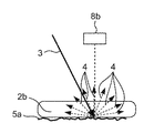
図3Aは、本実施の形態1を用いた、有効波長領域における拡散反射率が80%以上であり、かつ算術平均粗さRaが0.25〜25である選別対象物載置面5a上に樹脂2bを置いた場合の赤外線3の反射の模式図である。図3Bは、算術平均粗さRaが0.25未満である光沢面95上に樹脂2bを置いた場合の赤外線3の反射の模式図である。図3Cは、図2A、図3A、及び図3Bのそれぞれにおいて透明のPS樹脂2aを図2Aの載置面91と図3Aの選別対象物載置面5aと図3Bの光沢面95とにそれぞれ置いた場合の赤外線スペクトルを示す図である。
FIG. 3A shows the object to be sorted 5a using the first embodiment, which has a diffuse reflectance of 80% or more in the effective wavelength region and an arithmetic mean roughness Ra of 0.25 to 25. It is a schematic diagram of the reflection of
図3Aに示す通り、有効波長領域における拡散反射率が80%以上であり、かつ算術平均粗さRaが0.25〜25である選別対象物載置面5a上に樹脂2bを置いた場合は、照射光3が選別対象物載置面5aで拡散反射し、図3Cに示す通り、図1の受光部8bで多くの反射光4を樹脂2bから受光することができる。
それに対し、図2A及び図3Bに示す通り、算術平均粗さRaが0.25未満の載置面(すなわち、光沢面)95では、反射光4は照射光3の直接反射成分が多く、光沢面95からの拡散反射成分は少ない。従って、図3Cに示す通り、図1の受光部8bで多くの反射光4を受光することができない。また、図には記載していないが、算術平均粗さRaが25を越える載置面においても、拡散反射成分よりも直接反射成分が多くなるため、算術平均粗さRaが0.25未満の載置面と同程度のスペクトル測定結果を得た。
以上により、算術平均粗さRaが0.25未満の載置面及び算術平均粗さRaが25を越える載置面のそれぞれにおいて、透明PS樹脂2bでは、赤外線スペクトルの変化が少なく、樹脂種の判定が難しい。しかしながら、本実施の形態1のように、有効効波長領域における拡散反射率が80%以上であり、かつ算術平均粗さRaが0.25〜25である選別対象物載置面5aでは、透明PS樹脂2bでも大きな赤外線スペクトル変化を得ることができ、樹脂種の判定が可能となる。
As shown in FIG. 3A, when the
On the other hand, as shown in FIGS. 2A and 3B, on the mounting surface (that is, the glossy surface) 95 having an arithmetic mean roughness Ra of less than 0.25, the reflected
As described above, the
次に、図1の樹脂判定装置1の動作について、図4のフローチャートに基づいて説明する。
Next, the operation of the
まず、ステップS1において、樹脂2が、一定の速度で移動している載置部5上の投入領域6へ投入されて、載置部5の選別対象物載置面5a上に置かれ、検出領域7まで搬送される。
First, in step S1, the
次いで、ステップS2において、赤外線検出ユニット8は、検出領域7に到達しかつ選別対象物載置面5a上に置かれた樹脂2に、照射部8aからの照射光3を照射する。ここで、樹脂2は、載置部5上の投入領域6から載置部5に投入されたとき、有効波長領域における拡散反射率が80%以上であり、かつ算術平均粗さRaが0.25〜25である選別対象物載置面5a上に置かれた状態となっている。従って、選別対象物載置面5a上に載置された樹脂2に、照射部8aからの照射光3を照射することになる。
Next, in step S2, the infrared detection unit 8 irradiates the
次いで、ステップS3において、赤外線検出ユニット8は、検出領域7に到達しかつ照射光3が照射された樹脂2からの反射光4を検出する。
Next, in step S3, the infrared detection unit 8 detects the reflected light 4 from the
次いで、ステップS4において、赤外線検出ユニット8で検出した反射光4のアナログデータは、赤外線検出ユニット8からデジタルデータ変換部9を通して演算処理部10に出力される。デジタルデータ変換部9では、反射光4のアナログデータが、反射光4のデジタルデータに変換される。演算処理部10では、入力された反射光4のデジタルデータに基づいて、樹脂2の反射又は吸収スペクトルを算出したのち、反射又は吸収スペクトルに基づいて、樹脂判定用のスペクトル強度を取得する。
Next, in step S4, the analog data of the reflected
次いで、ステップS5において、スペクトル強度取得部10bで算出した樹脂判定用のスペクトル強度から、スペクトル評価部10cで、予め取得しておいた、物性が既知の樹脂である標本スペクトルと、スペクトル強度取得部10bで算出した樹脂判定用のスペクトル強度とより、相関情報の一例として、樹脂判定用のスペクトル強度と各標本スペクトルとの相関係数をスペクトル評価部10cでそれぞれ算出して評価する。
Next, in step S5, from the spectrum intensity for resin determination calculated by the spectrum
次いで、ステップS6において、各標本スペクトルとの相関係数と予め設定した閾値とを基に、閾値以上でかつ最も大きい相関係数に関連する樹脂種が、選別対象物の樹脂2の樹脂種であるとして、樹脂判定部10dで判定する。
Next, in step S6, based on the correlation coefficient with each sample spectrum and the preset threshold value, the resin type related to the correlation coefficient equal to or higher than the threshold value and the largest is the resin type of the
以上のように、本実施の形態1にかかる樹脂判定方法及び装置によれば、赤外光3の有効波長領域における拡散反射率が80%以上であり、かつ算術平均粗さRa0.25〜25である選別対象物2の載置面5a上に樹脂2を載置するように構成している。このように構成することにより、樹脂2に照射した照射光3が樹脂2で拡散反射し、樹脂2からの多くの反射光4を受光部8bで受光することができる。このため、赤外線を用いて透明樹脂2の樹脂種を高速に判定することができる。よって、選別対象物載置面5aでは、透明樹脂例えば透明PS樹脂2bでも大きな赤外線スペクトル変化を得ることができ、樹脂種の判定が可能となる。
As described above, according to the resin determination method and apparatus according to the first embodiment, the diffuse reflectance in the effective wavelength region of the
なお、前記様々な実施形態又は変形例のうちの任意の実施形態又は変形例を適宜組み合わせることにより、それぞれの有する効果を奏するようにすることができる。また、実施形態同士の組み合わせ又は実施例同士の組み合わせ又は実施形態と実施例との組み合わせが可能であると共に、異なる実施形態又は実施例の中の特徴同士の組み合わせも可能である。 In addition, by appropriately combining any embodiment or modification of the various embodiments or modifications, the effects of each can be achieved. Further, it is possible to combine the embodiments or the embodiments, or the embodiments and the embodiments, and also to combine the features in the different embodiments or the embodiments.
本発明の前記態様にかかる、樹脂判定方法及び装置を用いることにより、透明樹脂の樹脂種を判定することができる。従来、透明樹脂は、樹脂色に関わらず実施できる水比重選別装置での選別が主流であったが、樹脂を乾燥させる必要があり、かつ水に浮くかどうかでしか判定ができなかった。前記樹脂判定方法及び装置は、この課題を解決して赤外線を用いて透明樹脂の樹脂種を判定できることにより、さらなる樹脂の活用促進が可能となる。 By using the resin determination method and apparatus according to the above aspect of the present invention, the resin type of the transparent resin can be determined. Conventionally, transparent resin has been mainly sorted by a water specific gravity sorter that can be carried out regardless of the resin color, but it is necessary to dry the resin and it can be determined only by whether or not it floats on water. The resin determination method and apparatus can solve this problem and determine the resin type of the transparent resin using infrared rays, so that the utilization of the resin can be further promoted.
1 樹脂判定装置
2,2a,2b 樹脂
3 照射光
4 反射光
5 載置部
5a 選別対象物載置面
6 投入領域
7 検出領域
8 赤外線検出ユニット
8a 照射部
8b 受光部
9 デジタルデータ変換部
10 演算処理部
10b スペクトル強度取得部
10c スペクトル評価部
10d 樹脂判定部
91 黒色ベルト
92 透明樹脂
93 照射光
95 光沢面
1
Claims (4)
前記選別対象物である前記透明樹脂に前記赤外光を照射し、
前記赤外光を照射された前記選別対象物である前記透明樹脂を透過した前記載置面からの反射光を前記選別対象物である前記透明樹脂の上方で受光し、
前記反射光によって得られた反射又は吸収スペクトルにより樹脂種を判定する、樹脂判定方法。 The transparent resin to be sorted is placed on a mounting surface having an infrared light diffuse reflectance of 80% or more and an arithmetic mean roughness Ra of 0.25 to 25 μm in the effective wavelength region of infrared light. Place and
The transparent resin , which is the object to be sorted , is irradiated with the infrared light.
The reflected light from the above-mentioned mounting surface that has passed through the transparent resin, which is the object to be sorted, irradiated with the infrared light is received above the transparent resin, which is the object to be sorted.
A resin determination method for determining a resin type based on the reflection or absorption spectrum obtained by the reflected light.
前記選別対象物である前記透明樹脂に赤外光を照射する照射部と、
前記照射部から前記赤外光が照射された前記選別対象物である前記透明樹脂を透過した前記載置面からの反射光を前記選別対象物である前記透明樹脂の上方で受光する受光部と、
前記反射光に基づく前記選別対象物である前記透明樹脂の反射又は吸収スペクトルから、前記選別対象物である前記透明樹脂の樹脂種を判定する処理部と、
を備え、
前記載置面は、前記赤外光の有効波長領域における赤外光の拡散反射率が80%以上であり、かつ算術平均粗さRaが0.25〜25μmである、樹脂判定装置。 A mounting part on which the transparent resin to be sorted is placed on the mounting surface,
An irradiation unit that irradiates the transparent resin , which is the object to be sorted, with infrared light,
A light receiving unit that receives reflected light from the above-mentioned mounting surface that has passed through the transparent resin, which is the object to be sorted, irradiated with infrared light from the irradiation unit , above the transparent resin, which is the object to be sorted. ,
A processing unit that determines the resin type of the transparent resin that is the selection target from the reflection or absorption spectrum of the transparent resin that is the selection target based on the reflected light.
With
The above-mentioned mounting surface is a resin determination device having an infrared light diffuse reflectance of 80% or more in the effective wavelength region of the infrared light and an arithmetic mean roughness Ra of 0.25 to 25 μm.
Priority Applications (4)
| Application Number | Priority Date | Filing Date | Title |
|---|---|---|---|
| JP2017209070A JP6771190B2 (en) | 2017-10-30 | 2017-10-30 | Resin determination method and equipment |
| EP18197038.5A EP3477281B1 (en) | 2017-10-30 | 2018-09-27 | Resin determination method and resin determination apparatus |
| US16/158,048 US10466168B2 (en) | 2017-10-30 | 2018-10-11 | Resin determination method and resin determination apparatus |
| CN201811236190.1A CN109724935B (en) | 2017-10-30 | 2018-10-23 | Resin determination method and resin determination device |
Applications Claiming Priority (1)
| Application Number | Priority Date | Filing Date | Title |
|---|---|---|---|
| JP2017209070A JP6771190B2 (en) | 2017-10-30 | 2017-10-30 | Resin determination method and equipment |
Publications (2)
| Publication Number | Publication Date |
|---|---|
| JP2019082355A JP2019082355A (en) | 2019-05-30 |
| JP6771190B2 true JP6771190B2 (en) | 2020-10-21 |
Family
ID=63762209
Family Applications (1)
| Application Number | Title | Priority Date | Filing Date |
|---|---|---|---|
| JP2017209070A Active JP6771190B2 (en) | 2017-10-30 | 2017-10-30 | Resin determination method and equipment |
Country Status (4)
| Country | Link |
|---|---|
| US (1) | US10466168B2 (en) |
| EP (1) | EP3477281B1 (en) |
| JP (1) | JP6771190B2 (en) |
| CN (1) | CN109724935B (en) |
Families Citing this family (4)
| Publication number | Priority date | Publication date | Assignee | Title |
|---|---|---|---|---|
| JP6876983B2 (en) * | 2018-11-07 | 2021-05-26 | パナソニックIpマネジメント株式会社 | Resin determination method and equipment |
| EP4128027A1 (en) | 2020-03-26 | 2023-02-08 | Digimarc Corporation | Arrangements for digital marking and reading of items, useful in recycling |
| EP4323918A1 (en) | 2021-04-16 | 2024-02-21 | Digimarc Corporation | Methods and arrangements to aid recycling |
| WO2024015385A1 (en) | 2022-07-14 | 2024-01-18 | Digimarc Corporation | Methods and arrangements to utilize end-of-life data generated during recycling and waste sortation for counterfeit deterrence and other actions |
Family Cites Families (20)
| Publication number | Priority date | Publication date | Assignee | Title |
|---|---|---|---|---|
| JPS57136284A (en) | 1982-01-08 | 1982-08-23 | Toshiba Corp | Optical character reader |
| JPH05288671A (en) * | 1992-04-07 | 1993-11-02 | Nippon Steel Corp | Measuring method by infrared spectroscopy method for surface of steel plate |
| US6433338B1 (en) * | 1998-02-09 | 2002-08-13 | Tomra Systems Asa | Method and device for identification of a type of material in an object and utilization therefor |
| JP2004361148A (en) * | 2003-06-02 | 2004-12-24 | Tdk Corp | Water content measuring instrument |
| JP4971061B2 (en) * | 2007-07-23 | 2012-07-11 | 東洋鋼鈑株式会社 | Light reflecting plate, method for manufacturing the same, and light reflecting device |
| US8044354B2 (en) * | 2008-12-04 | 2011-10-25 | The Boeing Company | Method for classifying resins types in carbon fiber reinforced plastic materials using IR spectroscopy |
| JP5233963B2 (en) * | 2009-11-11 | 2013-07-10 | 三菱電機株式会社 | Resin identification device |
| JP2012021922A (en) * | 2010-07-16 | 2012-02-02 | Saika Gijutsu Kenkyusho | Quality measuring apparatus |
| WO2012035785A1 (en) | 2010-09-17 | 2012-03-22 | パナソニック株式会社 | Method for determining bromine-based flame retardant, bromine-based flame retardant determining device, recycling method, and recycling device |
| JP2012145528A (en) * | 2011-01-14 | 2012-08-02 | Mitsubishi Electric Corp | Resin type identification device |
| US8975586B2 (en) * | 2011-06-06 | 2015-03-10 | Honeywell Asca Inc. | Diffusing measurement window for near and mid IR multichannel sensor |
| JP5901453B2 (en) * | 2011-08-26 | 2016-04-13 | 三菱電機株式会社 | Resin identification apparatus and method |
| JP5877373B2 (en) * | 2012-05-16 | 2016-03-08 | パナソニックIpマネジメント株式会社 | Plastic mixture separation method and plastic mixture separation device |
| JP6137987B2 (en) * | 2013-01-21 | 2017-05-31 | 三菱電機株式会社 | Resin type identification method and resin type identification device |
| JP6160475B2 (en) | 2013-12-25 | 2017-07-12 | 株式会社島津製作所 | Resin identification method and apparatus |
| JP2015227832A (en) * | 2014-06-02 | 2015-12-17 | 栗田工業株式会社 | Ion exchange resin evaluation method |
| JP2016090476A (en) * | 2014-11-07 | 2016-05-23 | 住友電気工業株式会社 | Foreign matter detection method |
| JP2016142556A (en) * | 2015-01-30 | 2016-08-08 | 株式会社島津製作所 | Resin identification device |
| JP2017101988A (en) * | 2015-12-01 | 2017-06-08 | 株式会社島津製作所 | Plastic discrimination method and plastic discrimination device |
| CN106018330B (en) * | 2016-05-10 | 2019-03-22 | 四川长虹电器股份有限公司 | A kind of pocket-type near infrared spectrometer |
-
2017
- 2017-10-30 JP JP2017209070A patent/JP6771190B2/en active Active
-
2018
- 2018-09-27 EP EP18197038.5A patent/EP3477281B1/en active Active
- 2018-10-11 US US16/158,048 patent/US10466168B2/en active Active
- 2018-10-23 CN CN201811236190.1A patent/CN109724935B/en active Active
Also Published As
| Publication number | Publication date |
|---|---|
| CN109724935A (en) | 2019-05-07 |
| CN109724935B (en) | 2021-07-20 |
| EP3477281A1 (en) | 2019-05-01 |
| US10466168B2 (en) | 2019-11-05 |
| JP2019082355A (en) | 2019-05-30 |
| US20190128801A1 (en) | 2019-05-02 |
| EP3477281B1 (en) | 2023-11-15 |
Similar Documents
| Publication | Publication Date | Title |
|---|---|---|
| JP6771190B2 (en) | Resin determination method and equipment | |
| JP5290466B2 (en) | Brominated flame retardant determining method, brominated flame retardant determining device, recycling method, and recycling device | |
| CN108204954A (en) | Resin determination method and resin decision maker | |
| JP2014098555A (en) | Recycle resin determination system and manufacturing apparatus of recycled resin material | |
| JP6160475B2 (en) | Resin identification method and apparatus | |
| JP6876983B2 (en) | Resin determination method and equipment | |
| Tan et al. | Identification for recycling polyethylene terephthalate (pet) plastic bottles by polarization vision | |
| JPH08300354A (en) | Plastic classifying apparatus | |
| JP5229204B2 (en) | Plastic identification device and identification method thereof | |
| Cesetti et al. | Waste processing: new near infrared technologies for material identification and selection | |
| EP3477282B1 (en) | Method and apparatus determining resin color | |
| KR101919748B1 (en) | Color sorting apparatus having quality inspect unit | |
| Bonifazi et al. | Quality control by HyperSpectral Imaging (HSI) in solid waste recycling: logics, algorithms and procedures | |
| JP6771159B2 (en) | Resin determination method and equipment | |
| JP2017101988A (en) | Plastic discrimination method and plastic discrimination device | |
| JP6464489B2 (en) | Method and apparatus for determining specific brominated flame retardant | |
| JP2023182993A (en) | Resin determination method | |
| JP2002303575A (en) | Identification unit and sorting device | |
| Shelke et al. | An Automatic Grading System based on A Machine Vision | |
| JP2011089892A (en) | Apparatus, method, and program for identification of plastics | |
| KR20230063513A (en) | Apparatus for recycling PET resource | |
| JP2023025463A (en) | Waste plastic selection system and waste plastic selection method | |
| Reichert et al. | Photometric Sorting of cullet | |
| Nagori et al. | INTERNATIONAL JOURNAL OF ENGINEERING SCIENCES & RESEARCH TECHNOLOGY DETECTION OF RECYCLABLE AND NON-RECYCLABLE PLASTIC BY SPECTROSCOPY ANALYSIS |
Legal Events
| Date | Code | Title | Description |
|---|---|---|---|
| A621 | Written request for application examination |
Free format text: JAPANESE INTERMEDIATE CODE: A621 Effective date: 20190604 |
|
| A131 | Notification of reasons for refusal |
Free format text: JAPANESE INTERMEDIATE CODE: A131 Effective date: 20200303 |
|
| A977 | Report on retrieval |
Free format text: JAPANESE INTERMEDIATE CODE: A971007 Effective date: 20200228 |
|
| A521 | Request for written amendment filed |
Free format text: JAPANESE INTERMEDIATE CODE: A523 Effective date: 20200428 |
|
| A131 | Notification of reasons for refusal |
Free format text: JAPANESE INTERMEDIATE CODE: A131 Effective date: 20200616 |
|
| A521 | Request for written amendment filed |
Free format text: JAPANESE INTERMEDIATE CODE: A523 Effective date: 20200729 |
|
| TRDD | Decision of grant or rejection written | ||
| A01 | Written decision to grant a patent or to grant a registration (utility model) |
Free format text: JAPANESE INTERMEDIATE CODE: A01 Effective date: 20200901 |
|
| A61 | First payment of annual fees (during grant procedure) |
Free format text: JAPANESE INTERMEDIATE CODE: A61 Effective date: 20200911 |
|
| R151 | Written notification of patent or utility model registration |
Ref document number: 6771190 Country of ref document: JP Free format text: JAPANESE INTERMEDIATE CODE: R151 |