JP6769985B2 - Soft tissue tension application and attachment device - Google Patents
Soft tissue tension application and attachment device Download PDFInfo
- Publication number
- JP6769985B2 JP6769985B2 JP2017549061A JP2017549061A JP6769985B2 JP 6769985 B2 JP6769985 B2 JP 6769985B2 JP 2017549061 A JP2017549061 A JP 2017549061A JP 2017549061 A JP2017549061 A JP 2017549061A JP 6769985 B2 JP6769985 B2 JP 6769985B2
- Authority
- JP
- Japan
- Prior art keywords
- soft tissue
- base
- tension
- bone
- surgeon
- Prior art date
- Legal status (The legal status is an assumption and is not a legal conclusion. Google has not performed a legal analysis and makes no representation as to the accuracy of the status listed.)
- Active
Links
Images


Classifications
-
- A—HUMAN NECESSITIES
- A61—MEDICAL OR VETERINARY SCIENCE; HYGIENE
- A61F—FILTERS IMPLANTABLE INTO BLOOD VESSELS; PROSTHESES; DEVICES PROVIDING PATENCY TO, OR PREVENTING COLLAPSING OF, TUBULAR STRUCTURES OF THE BODY, e.g. STENTS; ORTHOPAEDIC, NURSING OR CONTRACEPTIVE DEVICES; FOMENTATION; TREATMENT OR PROTECTION OF EYES OR EARS; BANDAGES, DRESSINGS OR ABSORBENT PADS; FIRST-AID KITS
- A61F2/00—Filters implantable into blood vessels; Prostheses, i.e. artificial substitutes or replacements for parts of the body; Appliances for connecting them with the body; Devices providing patency to, or preventing collapsing of, tubular structures of the body, e.g. stents
- A61F2/02—Prostheses implantable into the body
- A61F2/08—Muscles; Tendons; Ligaments
- A61F2/0811—Fixation devices for tendons or ligaments
-
- A—HUMAN NECESSITIES
- A61—MEDICAL OR VETERINARY SCIENCE; HYGIENE
- A61F—FILTERS IMPLANTABLE INTO BLOOD VESSELS; PROSTHESES; DEVICES PROVIDING PATENCY TO, OR PREVENTING COLLAPSING OF, TUBULAR STRUCTURES OF THE BODY, e.g. STENTS; ORTHOPAEDIC, NURSING OR CONTRACEPTIVE DEVICES; FOMENTATION; TREATMENT OR PROTECTION OF EYES OR EARS; BANDAGES, DRESSINGS OR ABSORBENT PADS; FIRST-AID KITS
- A61F2/00—Filters implantable into blood vessels; Prostheses, i.e. artificial substitutes or replacements for parts of the body; Appliances for connecting them with the body; Devices providing patency to, or preventing collapsing of, tubular structures of the body, e.g. stents
- A61F2/02—Prostheses implantable into the body
- A61F2/08—Muscles; Tendons; Ligaments
-
- A—HUMAN NECESSITIES
- A61—MEDICAL OR VETERINARY SCIENCE; HYGIENE
- A61B—DIAGNOSIS; SURGERY; IDENTIFICATION
- A61B17/00—Surgical instruments, devices or methods, e.g. tourniquets
- A61B17/04—Surgical instruments, devices or methods, e.g. tourniquets for suturing wounds; Holders or packages for needles or suture materials
- A61B17/0401—Suture anchors, buttons or pledgets, i.e. means for attaching sutures to bone, cartilage or soft tissue; Instruments for applying or removing suture anchors
-
- A—HUMAN NECESSITIES
- A61—MEDICAL OR VETERINARY SCIENCE; HYGIENE
- A61B—DIAGNOSIS; SURGERY; IDENTIFICATION
- A61B17/00—Surgical instruments, devices or methods, e.g. tourniquets
- A61B2017/00004—(bio)absorbable, (bio)resorbable, resorptive
-
- A—HUMAN NECESSITIES
- A61—MEDICAL OR VETERINARY SCIENCE; HYGIENE
- A61B—DIAGNOSIS; SURGERY; IDENTIFICATION
- A61B17/00—Surgical instruments, devices or methods, e.g. tourniquets
- A61B2017/00367—Details of actuation of instruments, e.g. relations between pushing buttons, or the like, and activation of the tool, working tip, or the like
- A61B2017/00407—Ratchet means
-
- A—HUMAN NECESSITIES
- A61—MEDICAL OR VETERINARY SCIENCE; HYGIENE
- A61B—DIAGNOSIS; SURGERY; IDENTIFICATION
- A61B17/00—Surgical instruments, devices or methods, e.g. tourniquets
- A61B17/04—Surgical instruments, devices or methods, e.g. tourniquets for suturing wounds; Holders or packages for needles or suture materials
- A61B17/0401—Suture anchors, buttons or pledgets, i.e. means for attaching sutures to bone, cartilage or soft tissue; Instruments for applying or removing suture anchors
- A61B2017/044—Suture anchors, buttons or pledgets, i.e. means for attaching sutures to bone, cartilage or soft tissue; Instruments for applying or removing suture anchors with a threaded shaft, e.g. screws
-
- A—HUMAN NECESSITIES
- A61—MEDICAL OR VETERINARY SCIENCE; HYGIENE
- A61B—DIAGNOSIS; SURGERY; IDENTIFICATION
- A61B17/00—Surgical instruments, devices or methods, e.g. tourniquets
- A61B17/04—Surgical instruments, devices or methods, e.g. tourniquets for suturing wounds; Holders or packages for needles or suture materials
- A61B17/0401—Suture anchors, buttons or pledgets, i.e. means for attaching sutures to bone, cartilage or soft tissue; Instruments for applying or removing suture anchors
- A61B2017/0446—Means for attaching and blocking the suture in the suture anchor
- A61B2017/0448—Additional elements on or within the anchor
-
- A—HUMAN NECESSITIES
- A61—MEDICAL OR VETERINARY SCIENCE; HYGIENE
- A61B—DIAGNOSIS; SURGERY; IDENTIFICATION
- A61B17/00—Surgical instruments, devices or methods, e.g. tourniquets
- A61B17/04—Surgical instruments, devices or methods, e.g. tourniquets for suturing wounds; Holders or packages for needles or suture materials
- A61B2017/0496—Surgical instruments, devices or methods, e.g. tourniquets for suturing wounds; Holders or packages for needles or suture materials for tensioning sutures
-
- A—HUMAN NECESSITIES
- A61—MEDICAL OR VETERINARY SCIENCE; HYGIENE
- A61F—FILTERS IMPLANTABLE INTO BLOOD VESSELS; PROSTHESES; DEVICES PROVIDING PATENCY TO, OR PREVENTING COLLAPSING OF, TUBULAR STRUCTURES OF THE BODY, e.g. STENTS; ORTHOPAEDIC, NURSING OR CONTRACEPTIVE DEVICES; FOMENTATION; TREATMENT OR PROTECTION OF EYES OR EARS; BANDAGES, DRESSINGS OR ABSORBENT PADS; FIRST-AID KITS
- A61F2/00—Filters implantable into blood vessels; Prostheses, i.e. artificial substitutes or replacements for parts of the body; Appliances for connecting them with the body; Devices providing patency to, or preventing collapsing of, tubular structures of the body, e.g. stents
- A61F2/02—Prostheses implantable into the body
- A61F2/08—Muscles; Tendons; Ligaments
- A61F2/0811—Fixation devices for tendons or ligaments
- A61F2002/0817—Structure of the anchor
- A61F2002/0823—Modular anchors comprising a plurality of separate parts
- A61F2002/0829—Modular anchors comprising a plurality of separate parts without deformation of anchor parts, e.g. fixation screws on bone surface, extending barbs, cams, butterflies, spring-loaded pins
-
- A—HUMAN NECESSITIES
- A61—MEDICAL OR VETERINARY SCIENCE; HYGIENE
- A61F—FILTERS IMPLANTABLE INTO BLOOD VESSELS; PROSTHESES; DEVICES PROVIDING PATENCY TO, OR PREVENTING COLLAPSING OF, TUBULAR STRUCTURES OF THE BODY, e.g. STENTS; ORTHOPAEDIC, NURSING OR CONTRACEPTIVE DEVICES; FOMENTATION; TREATMENT OR PROTECTION OF EYES OR EARS; BANDAGES, DRESSINGS OR ABSORBENT PADS; FIRST-AID KITS
- A61F2/00—Filters implantable into blood vessels; Prostheses, i.e. artificial substitutes or replacements for parts of the body; Appliances for connecting them with the body; Devices providing patency to, or preventing collapsing of, tubular structures of the body, e.g. stents
- A61F2/02—Prostheses implantable into the body
- A61F2/08—Muscles; Tendons; Ligaments
- A61F2/0811—Fixation devices for tendons or ligaments
- A61F2002/0876—Position of anchor in respect to the bone
- A61F2002/0888—Anchor in or on a blind hole or on the bone surface without formation of a tunnel
-
- A—HUMAN NECESSITIES
- A61—MEDICAL OR VETERINARY SCIENCE; HYGIENE
- A61F—FILTERS IMPLANTABLE INTO BLOOD VESSELS; PROSTHESES; DEVICES PROVIDING PATENCY TO, OR PREVENTING COLLAPSING OF, TUBULAR STRUCTURES OF THE BODY, e.g. STENTS; ORTHOPAEDIC, NURSING OR CONTRACEPTIVE DEVICES; FOMENTATION; TREATMENT OR PROTECTION OF EYES OR EARS; BANDAGES, DRESSINGS OR ABSORBENT PADS; FIRST-AID KITS
- A61F2210/00—Particular material properties of prostheses classified in groups A61F2/00 - A61F2/26 or A61F2/82 or A61F9/00 or A61F11/00 or subgroups thereof
- A61F2210/0004—Particular material properties of prostheses classified in groups A61F2/00 - A61F2/26 or A61F2/82 or A61F9/00 or A61F11/00 or subgroups thereof bioabsorbable
-
- A—HUMAN NECESSITIES
- A61—MEDICAL OR VETERINARY SCIENCE; HYGIENE
- A61F—FILTERS IMPLANTABLE INTO BLOOD VESSELS; PROSTHESES; DEVICES PROVIDING PATENCY TO, OR PREVENTING COLLAPSING OF, TUBULAR STRUCTURES OF THE BODY, e.g. STENTS; ORTHOPAEDIC, NURSING OR CONTRACEPTIVE DEVICES; FOMENTATION; TREATMENT OR PROTECTION OF EYES OR EARS; BANDAGES, DRESSINGS OR ABSORBENT PADS; FIRST-AID KITS
- A61F2220/00—Fixations or connections for prostheses classified in groups A61F2/00 - A61F2/26 or A61F2/82 or A61F9/00 or A61F11/00 or subgroups thereof
- A61F2220/0008—Fixation appliances for connecting prostheses to the body
-
- A—HUMAN NECESSITIES
- A61—MEDICAL OR VETERINARY SCIENCE; HYGIENE
- A61F—FILTERS IMPLANTABLE INTO BLOOD VESSELS; PROSTHESES; DEVICES PROVIDING PATENCY TO, OR PREVENTING COLLAPSING OF, TUBULAR STRUCTURES OF THE BODY, e.g. STENTS; ORTHOPAEDIC, NURSING OR CONTRACEPTIVE DEVICES; FOMENTATION; TREATMENT OR PROTECTION OF EYES OR EARS; BANDAGES, DRESSINGS OR ABSORBENT PADS; FIRST-AID KITS
- A61F2250/00—Special features of prostheses classified in groups A61F2/00 - A61F2/26 or A61F2/82 or A61F9/00 or A61F11/00 or subgroups thereof
- A61F2250/0004—Special features of prostheses classified in groups A61F2/00 - A61F2/26 or A61F2/82 or A61F9/00 or A61F11/00 or subgroups thereof adjustable
- A61F2250/0012—Special features of prostheses classified in groups A61F2/00 - A61F2/26 or A61F2/82 or A61F9/00 or A61F11/00 or subgroups thereof adjustable for adjusting elasticity, flexibility, spring rate or mechanical tension
Description
本発明は軟組織を骨又は他の組織に添着させる装置及び方法に関し、これは例えば、前十字靱帯(ACL)又は環椎十字靱帯(CCL)の再建移植片(グラフト)に有用である。 The present invention relates to devices and methods for attaching soft tissue to bone or other tissue, which is useful, for example, in reconstructive grafts of the anterior cruciate ligament (ACL) or the cruciate ligament (CCL).
人間及び動物双方にとっての外科的処置は軟組織の固着を必要とすることがよくある。一般的な例の1つは、前十字靱帯(ACL)の再建である。ACL再建は外科的固着によく見られる問題を実証する。多くの割合(40%もの割合の多さ)の患者は、移植中又は術後に繰り返される負荷での張力喪失によって引き起こされる不満足な結果を体験する。外科医にとって、組織の張力及び安定性を正確に見積もりまた維持することができることは重要である。しかし、組織の張力を見積もりまた維持する外科医の能力は、据え付けが多段ステップを要するインプラントによって減殺され得る。固着処置中、多くの従来型デバイスは組織張力印加が一貫性のないもので、しばしば張力喪失を引き起こす結果となる。固着部位における術後滑脱も問題に関与する。多くの従来型デバイスの保持強度は、初期術後期間中の組織滑脱を防止するのには不十分である。術後リハビリテーションのための現行基準は強力な初期固着を要求している。しかし、多くの従来型デバイスが十分な強力固着を達成するのが不可能である場合、それは困難である。 Surgical procedures for both humans and animals often require soft tissue fixation. One common example is reconstruction of the anterior cruciate ligament (ACL). ACL reconstruction demonstrates a common problem with surgical fixation. A large proportion (as high as 40%) of patients experience unsatisfactory consequences caused by tension loss under repeated loading during or after transplantation. It is important for surgeons to be able to accurately estimate and maintain tissue tension and stability. However, the surgeon's ability to estimate and maintain tissue tension can be diminished by implants that require multi-step installation. During the fixation procedure, many conventional devices have inconsistent tissue tension applications, often resulting in tension loss. Postoperative slippage at the site of fixation is also involved in the problem. The retention strength of many conventional devices is insufficient to prevent tissue slippage during the initial postoperative period. Current standards for postoperative rehabilitation require strong initial fixation. However, it is difficult if it is not possible for many conventional devices to achieve sufficient strong fixation.
軟組織(例えば、腱)を相当な又は大きな強度及び剛性のある解剖学的構造(例えば、骨)に固着する従来の技術は、主に、ねじ、ワッシャ、ステープル、ピン等のような多様な伝統的金物デバイスに頼ってきた。このような従来型デバイスは、組織固着中に組織張力を維持する上で効果的ではない。そればかりか、処置中に組織張力印加に対する漸進的かつ安定的な調整をすることができない。従来型デバイスは、しばしば患者に対して採用する特定デバイスに固有であることがよくある複数の処置を要求し、これら複数の処置は、通常初回の外科的処置とは異質であり、またそうでない場合には不要である。骨トンネルを使用する場合、従来型デバイスは、トンネルから幾らかかの距離に配置することがよくある。ほとんどすべての従来デバイスの大きな欠点は、軟組織が固定されている間に適正な張力を維持する責務が劣悪である点である。本発明の発明者に既知の従来デバイスのいずれもが、添着プロセス中に組織張力印加を漸進的、可逆的、確実維持できるものではない。 Traditional techniques for anchoring soft tissues (eg, tendons) to anatomical structures (eg, bone) of considerable or greater strength and rigidity are predominantly diverse traditions such as screws, washers, staples, pins, etc. I have relied on the hardware device. Such conventional devices are not effective in maintaining tissue tension during tissue fixation. Not only that, it is not possible to make gradual and stable adjustments to tissue tension application during the procedure. Conventional devices often require multiple treatments that are often specific to the particular device adopted for the patient, and these multiple treatments are usually different from the initial surgical procedure and are not. Not needed in some cases. When using a bone tunnel, conventional devices are often placed at some distance from the tunnel. A major drawback of almost all conventional devices is the poor responsibility to maintain proper tension while the soft tissue is fixed. None of the conventional devices known to the inventor of the present invention can maintain gradual, reversible and reliable application of tissue tension during the attachment process.
多くの従来型デバイスの限界は、据え付けに要する時間、デバイス据付けに必要な他の異質処置、信頼性のない組織保持強度、添着処置中の組織張力喪失、及びしばしば他に用途がない特殊用途機器を必要としまた保守するための費用がかかることにある。 The limitations of many conventional devices are the time required for installation, other heterogeneous procedures required for device installation, unreliable tissue retention strength, loss of tissue tension during patching procedures, and often special purpose equipment with no other use. It is necessary and expensive to maintain.
エイミス氏らによる特許文献1(米国特許出願公開第2011/0112640号)は、靱帯移植片(グラフト)を骨に固着するグラフト固着デバイスを記載している。このデバイスは、骨内にデバイスを位置付けする位置付け手段と、グラフトを支持するよう構成されたグラフト支持手段であって、グラフトの骨に対する位置を調整することができる、該グラフト支持手段とを備える。グラフト支持手段は、調整を行うよう回転することができる。代案として、グラフト支持手段は、調整を行うため軸線方向に摺動又は容易に移動するよう構成することができる。 Patent Document 1 (US Patent Application Publication No. 2011/0112640) by Amis et al. Describes a graft fixation device for fastening a ligament implant (graft) to a bone. The device comprises a positioning means that positions the device within the bone and a graft supporting means that is configured to support the graft and is capable of adjusting the position of the graft with respect to the bone. The graft support means can be rotated to make adjustments. Alternatively, the graft support means can be configured to slide or move easily along the axis for adjustment.
メイ氏らによる特許文献2(米国特許第5,108,433号)は、靱帯又は腱に置換する補綴デバイスについて記載している。調整可能なコネクタが靱帯における張力の増減を可能にする。調整可能なコネクタの3つの実施形態、すなわち、1つはねじ山付きシャフトを有するピン及びねじ孔を有するシリンダを採用する実施形態、1つはラチェットプレート及びスプールを採用する実施形態、及びクリート(滑り止め)を採用する実施形態が記載されている。 Patent Document 2 by May et al. (US Pat. No. 5,108,433) describes a prosthetic device that replaces a ligament or tendon. Adjustable connectors allow the tension in the ligaments to increase or decrease. Three embodiments of the adjustable connector, one comprising a cylinder having pins and threaded holes with a threaded shaft, one embodiment adopting a ratchet plate and spool, and cleats ( Embodiments that employ non-slip) are described.
ジョンソン氏による特許文献3(米国特許第5,562,668号)は、靱帯グラフトの一方の端部を保持するねじ式張力印加デバイスについて記載している。
エルアトラッシェ(ElAttrache)氏らによる特許文献4(米国特許第6,544,281号)は、止まり穴又はソケットを骨におけるグラフトを固定すべき場所に形成する。好適には、次に縫合糸をグラフトの所望ポイントに挿通する。カニューレ挿入したドライバには、ドライバの末端部分に摺動可能に配置されるカニューレ挿入したプラグ又はねじを予め装填する。ドライバは、穴外部に配置したねじ又はプラグを穴内に挿入する。この後、縫合糸に張力を加える。適切な張力が縫合糸に達成された後、ドライバを穴内に圧入し、これによりねじ又はプラグの第1ねじ山又は凸部を骨に係合させる。次に、ドライバを使用して、ねじ又はプラグを穴内に完全に前進させる。 Patent Document 4 (US Pat. No. 6,544,281) by El Attrache et al. Form blind holes or sockets where grafts in bone should be anchored. Preferably, the suture is then inserted at the desired point of the graft. The cannulated driver is preloaded with a cannulated plug or screw that is slidably located at the end of the driver. The driver inserts a screw or plug placed outside the hole into the hole. After this, tension is applied to the suture. After proper tension has been achieved on the suture, a screwdriver is press-fitted into the hole, thereby engaging the first thread or ridge of the screw or plug with the bone. Then use a screwdriver to advance the screw or plug completely into the hole.
ロペス氏及びモンロー氏による特許文献5(米国特許第8,603,115号)は、ACL又はCCL再建に使用する軟組織固着デバイスを記載している。ベース部材は頂面から底面まで垂直に貫通する通路を有する。この通路は、軟組織が通り抜けることができるサイズとする。添着部材はベース部材に取付け可能とする。ベース部材は頂面に切欠き区域を有し、この切欠き区域は、通路からベース部材の第1周縁区域まで延在し、グラフトの少なくとも一部分を収容するサイズとする。ベース部材を骨に固定する。ベース部材には、さらにスリーブを設け、このスリーブの内壁面は、通路の一部を形成し、また骨開口内に挿入し得るサイズにする。添着部材には、下面から下方に垂下する一連の歯部材を設ける。これら歯部材は、添着部材をベース部材に取り付けるとき、歯部材がベース部材の頂面における切欠き区域にわたり、また切欠き区域内に突入するよう位置決めされる。添着部材の両側端部は、クリップ部材をベース部材に取り付けるため、ベース部材の底面の周縁区域に沿って位置決めされる整列した切欠き内に嵌合する形状とする。 Patent Document 5 by Lopez and Monroe (US Pat. No. 8,603,115) describes a soft tissue anchoring device used for ACL or CCL reconstruction. The base member has a passage that penetrates vertically from the top surface to the bottom surface. This passage is sized to allow soft tissue to pass through. The attachment member can be attached to the base member. The base member has a notch area on the top surface, which extends from the passage to the first peripheral area of the base member and is sized to accommodate at least a portion of the graft. Fix the base member to the bone. The base member is further provided with a sleeve, and the inner wall surface of the sleeve forms a part of the passage and is sized so that it can be inserted into the bone opening. The attachment member is provided with a series of tooth members that hang downward from the lower surface. These tooth members are positioned so that when the attachment member is attached to the base member, the tooth members extend over and into the notch area on the top surface of the base member. Both ends of the attachment member are shaped to fit into aligned notches positioned along the peripheral area of the bottom surface of the base member to attach the clip member to the base member.
さらに、以下に列挙する非特許文献1〜5も参照されたい。
Further, refer to
フーフ氏による特許文献6(米国特許第8,540,734号)は、執刀医が外科手術中にばね機構を用いて縫合糸に調整可能な張力を加えることができるようにする、調整可能なスタンドアロン型張力印加システムについて記載している。このデバイスは、手術中にツールとして使用するが、患者内に埋め込まれ、手術後にも患者内には留置しないよう設計されていることは明白である。このデバイスは、直接グラフト組織にではなく、縫合糸に張力を加えるよう設計されていること明らかである。 Patent Document 6 by Mr. Hoof (US Pat. No. 8,540,734) allows the surgeon to apply an adjustable tension to the suture using a spring mechanism during surgery. Describes a stand-alone tension application system. It is clear that this device is used as a tool during surgery, but is designed to be implanted in the patient and not indwell in the patient after surgery. It is clear that this device is designed to apply tension to the suture rather than directly to the graft tissue.
Lボド氏らによる以下の非特許文献6は、前十字靱帯再建のための「ループ・イン・ループ」技術について記載している。インプラントは、2つの部分、すなわち、滑らかな内面及び鋸歯状外面を有するプラスチックストラップ、及び鋸歯状ラッチを有するプラスチックリングを含む。これら2つの部分における2つの鋸歯状表面は、プラスチックストラップのリング内での一方向移動を可能にして、グラフトの締め込みを調整する。 The following Non-Patent Document 6 by L. Bod et al. Describes a "loop-in-loop" technique for anterior cruciate ligament reconstruction. The implant includes two parts: a plastic strap with a smooth inner surface and a serrated outer surface, and a plastic ring with a serrated latch. The two serrated surfaces in these two parts allow unidirectional movement within the ring of the plastic strap to adjust the tightening of the graft.
本願発明者は、大きな又は相当な強度及び剛性のある解剖学的構造(例えば、骨)の表面に対して、軟組織(例えば、腱又は靱帯)を安定的かつ信頼性高く添着する上で費用効果的及び時間効率の良い改良型デバイスを発見した。この新規な「GrabTenTM」は、特殊な処置又はツールを必要としない。単独デバイスが、添着しようとしている軟組織に対して張力及び圧縮力の双方を漸進的に印加する。GrabTenTMデバイスは、ユーザー、代表的には、医師又は獣医が組織張力を信頼性高く取扱い操作、制御及び維持できるようにする。デバイスは、多目的に使うことができ、また異なる軟組織タイプ及び異なる硬質組織タイプに適合することができる。これらの特徴は人間及び動物の健康に関する、整形外科、関節安定化、軟組織修復、脊髄手術、及び美容整形又は再建外科を含む様々な専門領域における開業医に対して、融通性を提供する。 The inventor of the present application is cost effective in stably and reliably adhering soft tissues (eg, tendons or ligaments) to the surface of a large or fairly strong and rigid anatomical structure (eg, bone). We have discovered an improved device that is both targeted and time efficient. This new "GrabTen TM " does not require any special treatment or tools. A single device progressively applies both tension and compressive force to the soft tissue to be adhered. GrabTen TM devices enable users, typically physicians or veterinarians, to reliably handle, control and maintain tissue tension. The device can be versatile and can be adapted to different soft tissue types and different hard tissue types. These features provide flexibility for practitioners in a variety of specialized areas of human and animal health, including orthopedics, joint stabilization, soft tissue repair, spinal cord surgery, and cosmetic or reconstructive surgery.
新規なデバイスは、調整可能に張力印加する添着デバイスである。このデバイスは、関節安定化処置(例えば、股関節、肩関節、肘関節、膝関節)に使用することができる。さらに、形成外科及び軟組織再建で様々な用途を有する。新規なデバイスは、軟組織修復処置、例えば、腱及び靱帯の断裂又は剥離を修復するのにも有用である。デバイスは、多目的に使うことができ、また多数のタイプの表面に添着される多数のタイプの組織に適合することができる。新規なデバイスは、何らばね機構を必要としない。デバイスは、好適にも、グラフトに直接張力を印加する。さらに、縫合糸を腱又は他の軟組織に取り付ける場合、張力を縫合糸に印加することもできる。 The new device is an adjustable tensioning device. The device can be used for joint stabilization procedures (eg, hip, shoulder, elbow, knee). In addition, it has a variety of uses in plastic surgery and soft tissue reconstruction. The novel device is also useful for soft tissue repair procedures, such as repairing ruptures or detachments of tendons and ligaments. The device can be versatile and can be adapted to many types of tissue attached to many types of surfaces. The new device does not require any spring mechanism. The device preferably applies tension directly to the graft. In addition, if the suture is attached to a tendon or other soft tissue, tension can be applied to the suture.
新規なデバイスは、片手で漸進的張力印加を可能にし、これに続いて固着を行うことができる。GrabTenTMデバイスを据え付けるのに、何ら特殊な処置又は機器を必要としない。このデバイスによれば、ユーザーが組織張力を信頼性高く取扱い操作及び維持できるようにする。デバイスは、外科医に対して「張力をダイヤル調整」することを可能にする。すなわち、外科医は、グラフトを張力の所望のマクロ又はグロスのレベルまで引っ張る。この後、外科医は、グラフトをデバイスの頂面部分に可逆的に固定し、またデバイスキャップを回転することによってこの張力を微調整することができ、さらにグラフトを骨トンネル内に前進させる。各「クリック」又は漸進的ステップで、張力は最終的に所望微調整チューニングに達するまでデバイス自体によって維持され、このポイントで、例えば、キャップをベースにスナップ嵌合することによってデバイスは所定位置に固定される。 The new device allows gradual tension application with one hand, followed by fixation. No special treatment or equipment is required to install the GrabTen TM device. The device allows the user to handle, operate and maintain tissue tension reliably. The device allows the surgeon to "dial adjust the tension". That is, the surgeon pulls the graft to the desired macro or gross level of tension. The surgeon can then reversibly secure the graft to the apical portion of the device and fine-tune this tension by rotating the device cap, further advancing the graft into the bone tunnel. At each "click" or gradual step, tension is maintained by the device itself until it finally reaches the desired fine-tuning tuning, at which point the device is locked in place, for example by snap-fitting to the base. Will be done.
このデバイスは、軟組織固着部位又はその近傍で骨トンネル又は他の組織表面上に着座させるよう設計する。 The device is designed to sit on a bone tunnel or other tissue surface at or near the soft tissue anchorage site.
このデバイスは、迅速かつ効率的に据え付けることができる。この初期的据付けに続く何らの順次処置(多くの従来型デバイスで行われる)は本質的に不要である。本発明デバイスは、添着処置中及び術後の双方において組織に対する張力を信頼性高く維持する。本質的に、標準的外科手術ツールの他には何らの特殊機器を使用する必要はない。 The device can be installed quickly and efficiently. No sequential action (as is done on many conventional devices) following this initial installation is essentially unnecessary. The device of the present invention reliably maintains tension on the tissue both during and after the patching procedure. In essence, there is no need to use any special equipment other than standard surgical tools.
図1A、1B、及び1Cに示す本発明による新規なデバイスの1つの実施形態は、3つの主要コンポーネント、すなわち、ベース3、組織張力印加のためベース3の周壁17内で回転可能な可動ディスク14、及び添着コンポーネント1を備える。グラフト組織は、ベース3における中空スリーブ12内に挿通し、また次に切欠き9に通す。この実施形態において、ベースは、「上方」から見たときに、同心円状の2つの形体を備える。本明細書及び特許請求の範囲の全体にわたり、他に明示しない限り、「上方(above)」、「垂直方向(vertical)」、「z軸線(z-axis)」、「頂部(top)」、「底部(bottom)」等、のような方向用語は、当然のことながら、全体的又は部分的に任意なものと解すべきである。このような方向用語は便宜的に使用する。それら用語は、他の方向用語に対する相対的な意味を有する、例えば、「頂部」方向は「底部」方向とは反対方向であると理解されたい。これら用語は、文脈が他に明示しない限り、全体方向(例えば、重力に対する上又は下の方向)を意味すると解すべきではない。
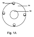
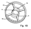
One embodiment of the novel device according to the invention shown in FIGS. 1A, 1B, and 1C is a
中空スリーブ12の長手方向軸線はz軸線を中心とする。中空スリーブの垂直方向中間点又はその近傍で、中空スリーブ12の外面は、連結スポーク7、例えばスポークの長手方向軸線はxy平面に平行である4個のスポーク7によって周壁17に取り付ける。スポーク7はスリーブ12の長さの中間点又はその近傍で中空スリーブ12に取り付ける。スリーブ12の中心軸線は、周壁17の中心軸線、すなわちz軸線に一致する。使用にあたり、スリーブ12は、z軸線に沿う負方向に延在する(例えば、ベース3の下方に突出し、また骨トンネル内に突出する)。中空スリーブ12の外面は、好適には、骨トンネルの内面に対して相互嵌合する、又は摩擦力を付与して抜け出しに抵抗しかつ回転に抵抗する一連のねじ山、出っ張り、又は突起を有する。スリーブ12は、さらに、z軸線に沿う正方向にスポーク7の頂面上方に延在する。スポーク7の底面は骨表面上に載置するよう設計する。スポーク7の底面は、好適には、骨表面に固定するのを支援するスパイク又は楔(図示せず)を有する。z軸線に沿う正方向に中空スリーブ12は互いに対向する2個の開口9を有する。(他の実施形態はスリーブ12に単独開口9を有する。)周壁17内でスポーク7のレベルの直ぐ上方において、周壁に互いに同一で等間隔離間する一連の歯16を有し、これら歯は、周壁17とスリーブ12との間の空間内に短い距離突出する。周壁17は、スリーブ12がz軸線正方向に延在する距離(すなわち、デバイスが所定位置にあるとき骨表面より上方の距離)のほぼ半分程度にz軸線正方向に延在する。ディスク14はスリーブ12を収容するサイズの中心孔18を有する。ディスク14はスリーブ12と周壁17との間の空間内に嵌合するサイズである。ディスク14の外端縁には、z軸線正方向にディスク14の表面から中心スリーブ12の高さのほぼ半分くらいまで突出する一連のペグ15を設ける。ペグ15は、周壁17における歯16と可逆的に相互嵌合し、これによりディスク14は、ディスク14が中心スリーブ12の周りに時計方向又は反時計方向に回転するとき、歯16及びペグ15の相互嵌合によって所定位置に保持することができる。グラフト又はグラフトに取り付けた縫合糸は、ペグに添着して、漸進的グラフト張力印加を可能にすることができる。(多くの場合、縫合糸は不要である。何らの縫合糸もない実施形態によれば、グラフトは添着部材とともに鉗子によって把持することができる、又はグラフトは添着部材又は可動ディスクにおけるペグ等に対してループ状にすることができる。)添着部材1は、好適には、幅狭い中心部分19及び幅広の端縁を有するアーチ状の形状とする。中心部分19における面取りを施した端縁、段差又は棚状部(図示せず)は、中心スリーブ12の骨から離れる方向(z軸線正方向)に延在する部分に設けた開口9における面取りを施した端縁、段差又は棚状部間で相互嵌合する。開口9はグラフト組織の挿通を可能にする。添着コンポーネント1の幅広端部は、好適には、やはり面取りを施した端縁、段差又は棚状部(図示せず)を有する周壁17の外面と相互嵌合する。したがって、添着部材1とベース3との間の距離は、中心及び周縁双方の局面で調整可能である。
The longitudinal axis of the
グラフトはディスク14を回転することにより漸進的に締め込まれる。所望の張力が得られたとき、添着部材1をベース3の切欠き9内に嵌挿する。添着部材1の両側端縁における突起と相互嵌合する切欠き9の周縁及び内端縁に突起を設け((図示せず)、グラフトを漸進的に圧迫できるようにする。
The graft is progressively tightened by rotating the
本発明の様々な実施形態は、概して相互に何らかの相違はあるものの同様に機能する。全体的には、多くの実施形態は以下のように機能する。すなわち、デバイスの中空スリーブを骨トンネル内に嵌合し、取り付けたベースを骨トンネルの周縁周りで骨表面に休止させる。軟組織(例えば、腱グラフト)は、スリーブに挿通し、スリーブの切欠きから骨表面(又は他の組織表面)上に退出させる。軟組織(又は軟組織に取り付けた縫合糸)は、ディスク(又は添着部材)の表面における1つ又はそれ以上のペグの周りに巻き付ける若しくは他のやり方で取り付ける。グラフトは、ディスク(又は添着部材)を回転することによって張力印加される。張力調整の各レベルにおいて、隣接表面の領域を含めていかなる関心対象領域における安定性も、確立した張力を損なうことなく試験することができる。安定的に維持される張力における漸進的変化を試験することによって、最適条件をより高い確かさで選択することができる。この後、組織は添着デバイスをベースに付加することによって、添着及び圧迫される。様々なサイズ、密度及び品質の組織が適合し得る。 The various embodiments of the present invention generally function in the same manner, with some differences from each other. Overall, many embodiments work as follows: That is, the hollow sleeve of the device is fitted into the bone tunnel and the attached base rests on the bone surface around the periphery of the bone tunnel. Soft tissue (eg, tendon grafts) is inserted through the sleeve and ejected from the notch in the sleeve onto the bone surface (or other tissue surface). The soft tissue (or suture attached to the soft tissue) is wrapped or otherwise attached around one or more pegs on the surface of the disc (or attachment member). The graft is tensioned by rotating the disc (or attachment member). At each level of tension adjustment, stability in any region of interest, including adjacent surface regions, can be tested without compromising established tension. Optimal conditions can be selected with greater certainty by testing gradual changes in tension that are maintained at a stable level. After this, the tissue is attached and compressed by adding the attachment device to the base. Tissues of various sizes, densities and qualities can be adapted.
概して、外科医は、組織グラフトを骨トンネル及びスリーブに引っ張り通すとき、張力の大部分を直接印加する。この後、スリーブ周りに組織グラフトを巻き付けることを用いて、張力に対する漸進的微調整を行う。通常、約360゜よりも多くない、又はそれより僅かに少ない角度にわたりグラフトを回転させるのが都合がよい。360゜よりも多い角度の回転は、グラフトのスリーブから突出する部分に対して過剰な摩擦及び応力を生ずる結果となり、また多くの場合推奨されない。約360゜の1回転又はそれより少ない回転は、多くの場合張力微調整するのに十分過ぎる。単一360゜回転によってもたらされるよりも大きい張力を必要とする場合、概して360゜を超えてデバイスの回転部分の調整を続行するよりもやり直すのが好ましい。 In general, the surgeon applies most of the tension directly when pulling the tissue graft through the bone tunnel and sleeve. This is followed by a gradual fine adjustment to tension using wrapping a tissue graft around the sleeve. It is usually convenient to rotate the graft over angles no more than or slightly less than about 360 °. Rotation at angles greater than 360 ° will result in excessive friction and stress on the portion protruding from the sleeve of the graft and is often not recommended. One or less rotation of about 360 ° is often more than sufficient for fine-tuning the tension. If greater tension is required than would be provided by a single 360 ° rotation, it is generally preferable to redo rather than continue adjusting the rotating portion of the device beyond 360 °.
スリーブは、周りにグラフトを巻き付けたとき、回転させることなく所定位置に留まる。キャップとベースとの間における相互嵌合する歯(又は同様の形体)は、張力が所望ポイントまで増加する際に一方向のみの回転を可能にする。グラフトの固着は、キャップとベースとの間にグラフトを圧迫することによって達成される。キャップ及びベースにおける構造部、例えば、棚状部、歯、ねじ山等は逆方向回転及び張力喪失を防止する。 The sleeve stays in place without rotation when the graft is wrapped around it. The interfitting teeth (or similar features) between the cap and base allow rotation in only one direction as tension increases to the desired point. Adhesion of the graft is achieved by compressing the graft between the cap and the base. Structural parts in the cap and base, such as shelves, teeth, threads, etc., prevent reverse rotation and loss of tension.
特別な組織固着が骨トンネルに関与しない場合、骨トンネル内に突入するスリーブの部分は省くことができる。 If no special tissue fixation is involved in the bone tunnel, the part of the sleeve that plunges into the bone tunnel can be omitted.
添着デバイスは、随意的にヒンジによってベースに取り付けることができる。(しかし、好適な実施形態はヒンジを設けない。) The collusion device can optionally be attached to the base by a hinge. (However, a preferred embodiment does not provide a hinge.)
回転ディスク(又は添着部材)及びベースにおける歯及びペグは種々の形態で構成することができ、例えば、歯を中心スリーブに配置し、かつペグをディスクの内面に配置する、又はその逆の構成にすることができる。様々な歯及びペグの相互嵌合形状を用いることができ、図示の特定形状には限定しない。 The teeth and pegs on the rotating disc (or attachment member) and base can be configured in various forms, for example, the teeth are located on the central sleeve and the pegs are located on the inner surface of the disc, or vice versa. can do. Mutual fitting shapes of various teeth and pegs can be used and are not limited to the specific shapes shown.
デバイスは、随意的に骨又は他の組織に隣接配置するベースの表面にフランジを設け、縫合糸、ワイヤ、ねじ、ステープル、又は他の添着機構の使用による安定化を支援できるようにする。 The device optionally flanges the surface of the base adjacent to the bone or other tissue to allow stabilization by the use of sutures, wires, screws, staples, or other attachment mechanisms.
骨スリーブの外面には、他の標準的タッピング手法を用いて骨と一体化する一連のねじ山を設ける。代案として、ねじ山は自己タッピング又は自己ロッキング式とすることができる。好適には、デバイス及びねじ山のピッチは、皮質骨の全厚にスリーブ柱状体(カラム)におけるねじ山を相互嵌合させるのを容易にするため、ベースの底面が骨と同一平面状になる前に約2回の完全回転できる構成とする。好適には、骨スリーブにおけるねじ山は、「後ずさり」又は「巻き戻り」を防止するため小さい「歯」を設ける。 The outer surface of the bone sleeve is provided with a series of threads that integrate with the bone using other standard tapping techniques. Alternatively, the threads can be self-tapping or self-locking. Preferably, the device and thread pitch makes the bottom surface of the base coplanar with the bone to facilitate the interfitting of the threads in the sleeve column over the full thickness of the cortical bone. It is configured so that it can be completely rotated about twice before. Preferably, the threads in the bone sleeve are provided with small "teeth" to prevent "backward" or "rewinding".
スリーブの骨上方に突出する中心部分を用いて、デバイス(2部材又は3部材の構成に係わらず)の張力印加を高めることができる。すなわち、中心「スリーブ」は、その周りにトルク又は張力を印加する軸として作用する。 The central portion of the sleeve protruding above the bone can be used to increase the tension application of the device (regardless of the configuration of the two or three members). That is, the central "sleeve" acts as a shaft around which torque or tension is applied.
ベース部材と添着部材との間における「ギア」又は「歯」の界面により漸進的張力印加を可能にする。その界面の位置は、ベースの外側、ベースの内側、スリーブ下面、又はスリーブ上面とすることができる。 The interface between the "gear" or "teeth" between the base member and the attachment member allows gradual tension application. The interface can be located on the outside of the base, inside the base, on the underside of the sleeve, or on the top of the sleeve.
グラフトを巻き付ける中心カラムは、グラフトの長さに沿って力を分配する摩擦を生じ、グラフトが添着部材とベースとの間に圧迫されるポイントにおける張力を軽減し、またグラフトが中心カラムにおける開口から退出するポイントにおける応力を軽減できるようにするのが好ましい。グラフトとデバイス表面との間の比較的大きな界面とともに、中心カラムをこのように使用することは、固着の安全性を向上させ、またデバイス自体により生ずるおそれのあるグラフトの離断又は他の損傷の可能性を大幅に低下させる。 The central column around which the graft is wrapped creates friction that distributes the force along the length of the graft, reducing tension at the point where the graft is compressed between the attachment member and the base, and the graft from the opening in the central column. It is preferable to be able to reduce the stress at the exit point. This use of the central column, along with the relatively large interface between the graft and the device surface, improves the safety of sticking and also prevents graft transection or other damage that may occur with the device itself. Greatly reduces the chances.
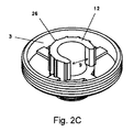
グラフトが中心カラムから退出するため、例えば図1Bに示すような2つの開口ではなく、例えば図2A及び2Bに示すような単に1個の開口を設けるのが好ましい。中心カラムからの開口は、骨トンネルからのグラフト運動を容易にし、かつ開口から退出するポイントにおけるグラフトの潜在的損傷を最小限にするよう滑らかに湾曲したものとする。 Since the graft exits the central column, it is preferable to provide, for example, just one opening as shown in FIGS. 2A and 2B, rather than two openings as shown in FIG. 1B, for example. The opening from the central column shall be smoothly curved to facilitate graft movement from the bone tunnel and to minimize potential damage to the graft at the point of exit from the opening.
例えば、グラフトを骨表面に固定するのにデバイスを使用するとき、グラフト通過用の骨トンネルは、先ずタッピングしてねじ山の跡付けをする。ベースから突出するスリーブを骨トンネル内に緊密になるまで前進させる。組織グラフトを骨トンネル及びベースの中空カラム内に挿通する。グラフトは開口(又はカラムにおける1つの開口)を通過させる。グラフトは開口に整列させ、これによりキャップ(又は添着部材)をベースに取り付けるときに圧潰又は損傷を受けないようにする。キャップは、キャップ中心における歯、及びベース頂部における歯が相互嵌合するよう位置決めする。幾つかの実施形態において、グラフトはキャップの外側リムにおける小さいフック又はノブに取り付ける。他の実施形態において、グラフトは、単に、鉗子又は他の外科手術ツールを用いて添着部材とともに掴持する。キャップを回転して、ベースにおける中心カラムの周りのグラフトに張力を印加する。所望の張力に達した後、ベース及びキャップの対応部分を所定位置にスナップ嵌合するまでキャップを押し込む。 For example, when using a device to secure a graft to a bone surface, the bone tunnel for graft passage is first tapped to mark a thread. Advance the sleeve protruding from the base into the bone tunnel until it is tight. The tissue graft is inserted into the bone tunnel and the hollow column of the base. The graft is passed through an opening (or one opening in the column). The grafts are aligned with the openings so that they are not crushed or damaged when the cap (or attachment member) is attached to the base. The cap is positioned so that the teeth at the center of the cap and the teeth at the top of the base fit together. In some embodiments, the graft is attached to a small hook or knob on the outer rim of the cap. In other embodiments, the graft is simply gripped with the attachment member using forceps or other surgical tools. Rotate the cap to apply tension to the graft around the central column in the base. After reaching the desired tension, push the cap in until the corresponding parts of the base and cap snap into place.
随意的に、添着部材、キャップ、及び回転ディスクのような素子は、デバイスを取扱い操作するための鉗子を挿入できるようにする孔又は切欠きを有することができる。これら形体は、標準的鉗子のような標準外科手術器具を用い、何ら特殊な又は専用の器具を使用せず、取扱い操作できるよう構成するのが好ましい。代案として、鉗子専用の孔又は切欠きを設けず、鉗子は単に、添着部材(又はキャップ)を回転し、軟組織を中心カラムの周りに巻き付けかつ張力を増加させるときに軟組織及び添着部材(又はキャップ)双方を保持するだけとする。 Optionally, elements such as attachment members, caps, and rotating discs can have holes or notches that allow forceps to be inserted for handling and manipulating the device. These features are preferably configured to be handled and operated using standard surgical instruments such as standard forceps and without the use of any special or specialized instruments. Alternatively, without providing a dedicated hole or notch for the forceps, the forceps simply rotate the soft tissue (or cap), wrap the soft tissue around the central column and increase tension when the soft tissue and the soft tissue (or cap) are increased. ) Only hold both.
種々の随意的又は代替的な形体をデバイスに組み込むことができ、例えば、添着部材又はキャップの側面に設けたペグを使用して、張力印加のためにグラフト又は縫合糸を取り付けるようにする。ベースにおける水平突起及び垂直突起を使用して、添着部材又はキャップの内面における対応の棚部又は歯と相互嵌合できるようにする。これらコンポーネントは、漸進的なグラフト張力印加を支援し、これに続く漸進的圧迫(棚状部による)を行って軟組織を圧迫し、かつ所定位置に固着する。添着部材、キャップ、又はベースにはグラフト組織を通過させ得る開口を設けることができる。ロック用ねじ山を骨スリーブに配置し、デバイスを骨トンネル内にロックするのを補助できるようにする。デバイスは、全体として2個又は3個のピースを有することができる。図1A〜1Cに示す実施形態は3ピース構成であり、一方図2A〜E及び3A〜Eに示す実施形態は2ピース構成である。 A variety of optional or alternative features can be incorporated into the device, eg, using pegs on the sides of the attachment member or cap to attach the graft or suture for tension application. Horizontal and vertical protrusions on the base are used to allow interfitting with the corresponding shelves or teeth on the inner surface of the attachment member or cap. These components assist in the application of gradual graft tension, followed by gradual compression (due to the shelves) to compress the soft tissue and anchor it in place. The attachment member, cap, or base may be provided with an opening through which the graft structure can pass. A locking thread is placed on the bone sleeve to help lock the device into the bone tunnel. The device can have two or three pieces as a whole. The embodiments shown in FIGS. 1A to 1C have a three-piece configuration, while the embodiments shown in FIGS. 2A to E and 3A to E have a two-piece configuration.
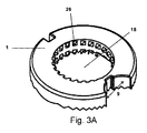
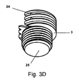
代替的実施形態を図2A〜E及び3A〜Eに示す。異なる図面に示される同一参照符号は、異なる実施形態における対応する又は類似するコンポーネントに言及するが、その形状及びサイズはときに実施形態毎に変化し得るものと理解されたい。 Alternative embodiments are shown in FIGS. 2A-E and 3A-E. It should be understood that the same reference numerals shown in different drawings refer to corresponding or similar components in different embodiments, but their shapes and sizes can sometimes vary from embodiment to embodiment.
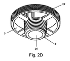
図2A〜Eに示す代替的実施形態(ときに、「GrabTenTMV1」と称される実施形態)において、スリーブ12の下方ねじ山付き部分を骨トンネル、例えば、脛骨の骨トンネル内に固定する。腱グラフトをスリーブ12の中心部分25に挿通する。外科医は、単に鉗子でグラフトをスリーブ12内に引っ張り込むことによって、初期的にグラフトに対して張力印加する。キャップ1は、初期的に開放状態にあるベース3の上方に位置決めし、またグラフトをスリーブ12における開口25並びにベース3及びキャップ1における開口9に挿通する。キャップ1における開口9は、ベース3のスリーブ12における開口9上に配置すべきである。開放状態では、キャップ1の棚状部20の下方がベース3の棚状部22の上方に相互嵌合する。ベース3及びキャップ1における棚状部は、好適には、ねじ山(ピッチがある)ではなく棚状部(ピッチがない)とし、これによりキャップ1はベース3の周りに自由に回転できるものとする。グラフト及びキャップ1を鉗子で掴持し、またキャップ1と回転させ、グラフトがスリーブ12の周りに巻き付くにつれてグラフトに張力を漸進的に印加する。キャップ1の開口18における周縁の歯24、及びスリーブ12の歯26により、デバイスをラチェット及びつめとして作用させ、一方向のみの回転を可能にする。キャップ1は、張力を調整するため、330゜(約6ラジアン)よりも大きくない角度にわたり回転できるようにすべきである。張力を追加するのが望ましい場合、回転を継続するよりも、キャップ1を取り外し、グラフトをスリーブ12から巻き戻し(張力を釈放することなく)、プロセスを再開するのが好ましい。特定デバイスにおける寸法に基づいて、このプロセスは、代表的には約2cmの微調整張力印加を可能にし、たいていの場合、これで十分である。張力印加プロセスが完了した後、外科医は以下のいずれかを行うことができる。すなわち、(1) グラフトを鉗子から釈放し、キャップ1の回転を継続し、このとき、グラフト「尾部(テール)」は、追加張力を印加することなくスリーブ12の周りに巻き付いており、デバイス内に拘束されている;又は(2) キャップ外部に残留するグラフトのいかなる部分をも切除する。最終的に、キャップ1をグラフト上で密にスナップ嵌合し、図2E及び2Fに示すようにグラフトを圧迫し、所定位置に固着する。キャップ1の棚状部20及びベース3の棚状部22は相互嵌合し、キャップ1及びグラフトを保持し、これによりグラフトを圧迫及び添着する。
In an alternative embodiment shown in FIGS. 2A-E (sometimes referred to as "GrabTen TM V1"), the lower threaded portion of the
図3A〜Eに示す代替的実施形態(ときに、「GrabTenTMV2」と称される実施形態)において、ベース3の下方ねじ山付き部分を骨トンネル、例えば、脛骨の骨トンネル内に固定する。腱グラフトをベース3の中心開口25に挿通する。グラフトは引っ張ることによって張力印加する。キャップ1は、先にV1実施形態で説明したのと同様に、初期的に開放状態に位置決めし、またグラフトをベース3及びキャップ1における開口9に挿通し、キャップ1における開口9を、ベース3における開口9上に配置する。グラフトは、鉗子又は他の外科手術ツールを用いて添着部材とともに掴持する。キャップ1を回転して、ベース3周りのグラフトに漸進的に張力を印加する。ベース3及びキャップ1のそれぞれに歯24及び26を有するねじ山を設ける。キャップ1が回転するとき、キャップはベース3に沿ってゆっくりと下って前進し、これはすなわち、双方のコンポーネントにねじ山が存在するからである。ベース3及びキャップ1の歯24及び26は、キャップ1が逆方向に回転して張力を弛めるのを防止する。張力印加プロセスが完了した後、外科医は以下のいずれかを行うことができる。すなわち、(1) グラフトを鉗子から釈放し、キャップ1の回転を継続し、このとき、グラフト「尾部(テール)」は、追加張力を印加することなくベース3の周りに巻き付いており、デバイス内に拘束されている;又は(2) キャップ外部に残留するグラフトのいかなる部分をも切除する。最終的には、キャップ1をさらに回転してグラフトを圧迫し、所定位置に固着する。この「閉鎖」状態において、キャップ1の下面は、代表的には骨表面の上方約1〜2mm上方にある。張力印加はキャップ1をベース3の周りに第1回目の回転により達成され、また圧迫は第2回目の回転により達成される。「V2」の実施形態は、上述したように、キャップ1が2回の全回転を受けるよう設計するのが好ましい。第1回目の回転では張力達成が不十分な場合、グラフトを巻き戻し、またそのプロセスを新たに開始することができる。デバイスは主に張力の微調整を意図し、張力のほとんどは、外科医がグラフトを骨トンネル及びカラムで引っ張ることによって直接的に印加される。
In an alternative embodiment shown in FIGS. 3A-E (sometimes referred to as "GrabTen TM V2"), the lower threaded portion of the
新規な本発明によるGrabTenTMデバイスは様々な用途があり、例えば、前/後十字靭帯再建、半月板修復、回旋腱板修復、肩関節唇修復、及び二頭筋腱固定術がある。デバイスの寸法は、意図する用途、患者のサイズ、及び患者の人種に合わせてカスタマイズすることができる。デバイスは、人間、犬、猫、馬、及び他の脊椎動物に使用することができる。随意的に、本発明デバイスは生体吸収性材料から作製することができる。 The novel GrabTen TM devices according to the invention have a variety of uses, including, for example, anterior / posterior cruciate ligament reconstruction, meniscal repair, rotator cuff repair, shoulder lip repair, and biceps tendon fusion. The dimensions of the device can be customized for the intended use, patient size, and patient race. The device can be used for humans, dogs, cats, horses, and other vertebrates. Optionally, the device of the invention can be made from a bioabsorbable material.
代替的実施形態において、添着部材の周縁及びベースにおける凹み形状は、円形形状ではなく、正多角形形状(例えば、正方形、正六角形、正八角形等々)にすることができ、これにより添着部材の多角形外形がベースの多角形凹み内にぴったり嵌合できるようにする。これらの多角形形状の角部及び全体的相対嵌合は、グラフトの漸進的張力印加のための捕捉部、突起部、歯部、ギア部等に取って代わる。張力は、添着部材を1つの相補的位置から次の相補的位置に回転することによって保持され、例えば、正方形の場合90゜回転する、六角形の場合60゜回転する、八角形の場合45゜回転する等によって保持される。この代替的実施形態におけるそれ以外の全体的機能はほぼ類似する。漸進的張力増進は、やはりベースと添着部材との間における相互嵌合によって固定されるが、この実施形態における相互嵌合は、段差、楔状部、ギア又はペグのような特定表面変更ではなく、コンポーネント自体の形状の結果である。 In an alternative embodiment, the recessed shape at the periphery and base of the anchoring member can be a regular polygonal shape (eg, square, regular hexagon, regular octagon, etc.) instead of a circular shape, thereby resulting in more attachment members. Allows the square outline to fit snugly within the polygonal recess of the base. The corners and overall relative fitting of these polygons replace traps, protrusions, teeth, gears, etc. for the gradual tension application of the graft. Tension is maintained by rotating the attachment member from one complementary position to the next, for example 90 ° for a square, 60 ° for a hexagon, 45 ° for an octagon. It is held by rotating or the like. Other overall functions in this alternative embodiment are similar. The gradual tension increase is also fixed by mutual fitting between the base and the anchoring member, but the mutual fitting in this embodiment is not a specific surface modification such as a step, wedge, gear or peg. It is the result of the shape of the component itself.
より全般的には、この代替的実施形態において、正多角形のような形状であることすら必要でなく、より広くは回転対称の任意な形状、2つを互いに圧嵌するとき添着部材とベースとの間でぴったりとした嵌合を生じ、これにより添着部材が所定位置から容易に滑動しないようにする任意な形状とすることができる。例えば、形状は、楕円形、長方形、星形(例えば、5,6,7,8個又はそれ以上のポイントがある)、三つ葉状、五つ葉状、六つ葉状、八つ葉状、等とすることができる。 More generally, in this alternative embodiment, it is not even necessary to have a regular polygonal shape, but more broadly any shape that is rotationally symmetric, and when the two are pressed together, the anchoring member and the base It can be of any shape that results in a snug fit with and from which the attachment member does not easily slide from a predetermined position. For example, the shape may be oval, rectangular, star-shaped (eg, with 5, 6, 7, 8 or more points), trefoil, five-leaf, six-leaf, eight-leaf, etc. be able to.
試作品
ACLに使用し得る寸法の新規デバイスの試作品は、医療グレードのポリ-L-乳酸から作製する。機械的試験は、先ず人間用インプラントのために確立された動物モデル(仔牛の死体からの四肢)で行い、次に生きた動物での試験、次に生きた人間での試験を行い、これら試験はすべて適用可能な法律及び規則に則って行う。
Prototypes Prototypes of new devices with dimensions that can be used for ACLs are made from medical grade poly-L-lactic acid. Mechanical tests are first performed on an established animal model for human implants (limbs from calf carcasses), then on live animals, then on live humans, and these tests. Are all in accordance with applicable laws and regulations.
この研究とは無関係な理由から安楽死させられた仔牛達から採取した16個の膝関節(大腿骨から足根骨にかけての中間にある)を生理食塩水に浸漬したタオルで包み、プラスチック密封袋内に二重にラップし、グラフト採取及び固化が達成されるまで−20℃で凍結する。グラフト採取前に、四肢は2つの処理グループ、すなわち、(1) 新規なGrabTenTMデバイスの実施形態又は(2) 従来型ねじ及びワッシャのグループにランダムに割り当てる。ハムストリング筋腱グラフトを採取及び調製する。端的に言うと、半腱様筋及び薄筋の付着点をそれらの筋性起始部から解離する。腱付着点を阻害することなく、鈍的剥離及び鋭利的剥離を組み合わせて頭蓋脛骨筋の付着した密な結合組織又は筋膜を脛骨の遠位1/3まで持ち上げ、この部分で組織はくっきりと離断する。持ち上げられた組織を切除し、また捻じって約10mmの最終直径にする。グラフトはポリグラクチン910で形成した「チャイニーズ・フィンガー・トラップ」内に包み込む。 16 knee joints (in the middle from the femur to the tarsal bone) taken from euthanized calves for reasons unrelated to this study were wrapped in a towel soaked in saline and a plastic sealed bag. Double wrap in and freeze at -20 ° C until graft collection and solidification is achieved. Prior to grafting, the limbs are randomly assigned to two processing groups: (1) a new GrabTen TM device embodiment or (2) a conventional screw and washer group. Collect and prepare hamstring muscle tendon grafts. Simply put, the attachment points of the semitendinosus and gracilis muscles are dissociated from their muscular origin. A combination of blunt and sharp detachment lifts the tight connective tissue or fascia with the tibialis anterior muscle to the distal third of the tibia without interfering with the tendon attachment point, where the tissue is crisp. Disconnect. The lifted tissue is excised and twisted to a final diameter of about 10 mm. The graft is wrapped in a "Chinese finger trap" formed of polygrantin 910.
脛骨をインストロン機械式試験システムに取り付けた試験治具に固定する。各グラフトの一方の端部は、脛骨に固着するのに十分な長さを有するロードセルに取り付けたクライオグリップ(cryogrip)内に保持する。これに続く他の標準手順で、グラフトを骨トンネル内に配置し、またGrabTenTMデバイス又は従来式のねじ及びワッシャのいずれかで固定する。このプロセス中、及びグラフト固着後に5分間にわたる継続中に張力を測定する。グラフトは、グラフトの生理学的軸線に沿って印加される軸線方向負荷の下において単一サイクルの破損を試験する。剛性、降伏、破損負荷及びエネルギーを決定する。 Secure the tibia to a test jig attached to the Instron mechanical test system. One end of each graft is held within a cryogrip attached to a load cell that is long enough to adhere to the tibia. In other standard procedures that follow, the graft is placed in the bone tunnel and secured with either a GrabTen TM device or conventional screws and washers. Tension is measured during this process and for 5 minutes after graft fixation. The graft is tested for a single cycle of fracture under an axial load applied along the physiologic axis of the graft. Determine stiffness, yield, break load and energy.
生化学的試験としては、とくに、破損までの単一サイクル試験、疲労試験、漸進的張力印加定量化、及びクリープ試験がある。デバイスの実施形態を他の実施形態に対して、並びに市販のデバイスに対して比較する。安全性及び有効性を確立するため、適切サイズのデバイスを有する認可モデルで標準的前臨床試験を行う。適用可能な法律及び規則に則って臨床試験を行う。 Biochemical tests include, in particular, a single cycle test to breakage, a fatigue test, a gradual tension application quantification, and a creep test. The embodiment of the device is compared to other embodiments as well as to commercially available devices. Standard preclinical studies are performed on approved models with appropriately sized devices to establish safety and efficacy. Conduct clinical trials in accordance with applicable laws and regulations.
統計的分析
研究の入れ子式要因計画に起因して、パラメータ応答変数を連続的に処理し、またp≦0.05で排除する帰無仮説とともにシャピロ・ウィルク統計の使用により正規性を試験する。非正規データを変換する。分散の多変量解析を行い、共線的応答変数におけるグラフト固着の固定効果を評価する。群内に入れ子にされた構成要因のランダム分散は、グラフト固着効果に対するエラー項として使用する。統計的有意性はp≦0.05で評価される。
Statistical analysis Due to the nested factorial design of the study, the parameter response variables are processed continuously and the normality is tested by using the Shapiro-Wilk statistics with the null hypothesis to eliminate at p ≤ 0.05. Convert non-regular data. Multivariate analysis of variance is performed to evaluate the fixation effect of graft fixation on collinear response variables. Random dispersion of the components nested within the group is used as an error term for the graft fixation effect. Statistical significance is assessed at p ≦ 0.05.
期待された結果
() GrabTenTMインプラントで固着したハムストリングACL再建グラフトは、同一目的用に設計された他のデバイス、例えば、ねじ及びワッシャで固着したものよりも高い一貫性及び安定張力印加挙動を有する。(2) GrabTenTMインプラントで固着したハムストリングACL再建グラフトは、同一目的用に設計された他のデバイス、例えば、ねじ及びワッシャを採用するものよりも優れた機械的特性を有する。
Expected result
() GrabTen TM implant-fixed hamstring ACL reconstructive grafts have higher consistency and stable tension application behavior than other devices designed for the same purpose, such as those fastened with screws and washers. (2) Hamstring ACL reconstruction grafts anchored with GrabTen TM implants have better mechanical properties than those that employ other devices designed for the same purpose, such as screws and washers.
用語体系及び若干の代替的実施形態に関する注記
本明細書及び特許請求の範囲では、ときに、用語「グラフト」、「グラフト組織」及び「軟組織」を互換的に使用する。幾つかの文脈において、語句「グラフト」は幾つかの場所から採取した組織について言及するとともに、「軟組織」はこのような含意は何ら持たず、しばしば腱又は靭帯を同一場所に再取付けすべき場合に使用する。しかし、本発明及びその使用方法について説明する目的のために、概して組織が真に「グラフト」であるか、又は同一場所に再取付けする組織であるかを問題にしない。したがって、他の文脈で重要となり得るこれらの区別は、文脈が他に明示しない限りにおいて、本明細書及び特許請求の範囲を読むとき適切でないと捉えるべきではない。本発明は、異なる場所から採取した「グラフト組織」及び同一場所に再取付けされる軟組織の双方で機能する。さらに、軟組織に取り付けられる縫合糸又は合成材料を併用することができる。本発明の最も一般的な用途は、腱及び靭帯の取付け又は再取付けが期待されるが、他のタイプの組織にも、例えば、皮膚グラフト、又は膀胱スリングの支持体に使用することができる。取付けは、概して骨に対して行うが、幾つかのケースにおいて、他の軟組織の表面に対して行うことができる。上述のすべては、特定場所に使用される特定用語体系に無関係に本発明の範囲内にあると見なされる。
Note on terminology and some alternative embodiments The terms "graft", "graft structure" and "soft tissue" are sometimes used interchangeably herein and in the claims. In some contexts, the phrase "graft" refers to tissue taken from several locations, while "soft tissue" has no such implications and often the tendon or ligament should be reattached in the same location. Used for. However, for the purposes of describing the present invention and its use, it does not generally matter whether the tissue is truly a "graft" or a tissue that is reattached in the same place. Therefore, these distinctions, which may be important in other contexts, should not be considered inappropriate when reading the specification and claims unless the context explicitly states otherwise. The present invention works with both "graft tissue" taken from different locations and soft tissue reattached to the same location. In addition, sutures or synthetic materials attached to soft tissue can be used in combination. The most common use of the present invention is expected to be the attachment or reattachment of tendons and ligaments, but other types of tissue can also be used, for example, for skin grafts, or supports for bladder slings. Attachment is generally made to bone, but in some cases it can be made to the surface of other soft tissues. All of the above are considered to be within the scope of the invention regardless of the particular terminology used in the particular location.
本明細書で引用した参考文献の記載全体は、優先権主張米国特許出願第62/145,552号の記載全体を含めて、参照により本明細書に組み入れられるものとする。しかし、他に相いれない矛盾がある場合、本明細書が統制する。 The entire description of the references cited herein, including the entire description of Priority Claim U.S. Patent Application No. 62 / 145,552, shall be incorporated herein by reference. However, if there are other conflicting conflicts, this specification controls.
1 添着コンポーネント(部材)
3 ベース
7 (連結)スポーク
9 切欠き(開口)
12 (中空)スリーブ
14 (可動)ディスク
15 ペグ
16 歯
17 周壁
18 中心孔(開口)
19 中心部分
20 棚状部
22 棚状部
24 歯
25 中心部分(開口)
26 歯
1 Attached component (member)
3 Base 7 (Connected)
12 (hollow) sleeve 14 (movable)
19
26 teeth
Claims (19)
(a) 前記ベースは、
(i) 頂面及び底面と、
(ii) 前記底面から前記頂面にかけて貫通する通路であって、軟組織を挿通し得る滑らかな側面を有する、該通路と、
(iii) 前記頂面において前記通路から延在する少なくとも1つの開口であって、前記開口のそれぞれは、軟組織を挿通し得る1つ又はそれ以上の滑らかな端縁を有する、該少なくとも1つの開口と、
(iv) 前記ベースを骨表面又は他の組織表面に固定し得る、前記底面における少なくとも1つの素子と、
(v) 前記頂面における凹みと、
を備え、
(b) 前記回転体は、前記凹み内に確実に嵌合するよう構成され、軟組織を挿通することができる中心開口を有し、また軟組織に確実に取り付ける、又は軟組織に取り付けられた縫合糸に確実に取り付けるよう構成された少なくとも1つの形体を有するものであり、
(c) 前記凹み内に含まれる、又は前記回転体に含まれる、又はその双方に含まれる複数個の固定素子であって;前記固定素子は、前記回転体が軟組織又は軟組織に取り付けられた縫合糸に確実に取り付けられた状態に留まる間に、外科医によって選択される複数の位置のうち任意な1つの位置に前記回転体を確実に保持し、またこれにより前記回転体は安定した張力を前記軟組織に印加するよう構成され;また前記固定素子は、外科医が前記回転体の選択した位置を容易に変更できるよう構成され、これにより、外科手術中に前記軟組織に印加される張力を安定的に外科医が容易に変更できるよう、また外科医によって選択される張力量を安定して印加する位置を外科医が選別できるようになる、該複数個の固定素子を備え、並びに
(d) 前記添着部材は、前記選別した位置を維持する間に前記回転体を前記ベースに恒久的に添着し、またこれにより前記軟組織を前記ベースに添着するよう構成され、また軟組織が前記添着部材と前記ベースとの間に圧迫されるとき前記軟組織に対する選択した張力量を維持して外科手術を続けられるよう構成されている、デバイス。 In a device that includes a base, a rotating body and an adhering member and is capable of adhering soft tissue to a bone surface or other tissue surface.
(a) The base is
(i) Top and bottom,
(ii) A passage that penetrates from the bottom surface to the top surface and has a smooth side surface through which soft tissue can be inserted.
(iii) At least one opening extending from the passage on the top surface, each of which has one or more smooth edges through which soft tissue can be inserted. When,
(iv) With at least one element on the bottom surface capable of anchoring the base to a bone surface or other tissue surface.
(v) The dent on the top surface and
With
(b) The rotating body is configured to fit securely into the recess, has a central opening through which soft tissue can be inserted, and is securely attached to or attached to soft tissue to a suture. It has at least one feature configured to be securely attached and
(c) A plurality of fixing elements included in the recess, included in the rotating body, or included in both; the fixing element is a suture in which the rotating body is attached to soft tissue or soft tissue. While remaining securely attached to the thread, it reliably holds the rotating body in any one of a plurality of positions selected by the surgeon, which causes the rotating body to maintain a stable tension. It is configured to apply to the soft tissue; and the fixation element is configured to allow the surgeon to easily change the position of the rotating body of choice, thereby stabilizing the tension applied to the soft tissue during surgery. The plurality of fixation elements are provided so that the surgeon can easily change the position and the position where the tension amount selected by the surgeon is stably applied can be selected by the surgeon.
(d) The attachment member is configured to permanently attach the rotating body to the base while maintaining the sorted position, thereby attaching the soft tissue to the base, and the soft tissue is attached to the base. A device configured to maintain a selected amount of tension on the soft tissue and continue surgery when compressed between a member and the base.
(a) 前記ベースは、
(i) 頂面及び底面と、
(ii) 前記底面から前記頂面にかけて貫通する通路であって、軟組織を挿通し得る滑らかな側面を有する、該通路と、
(iii) 前記頂面において前記通路から延在する少なくとも1つの開口であって、前記開口のそれぞれは、軟組織を挿通し得る1つ又はそれ以上の滑らかな端縁を有する、該少なくとも1つの開口と、
を備え、
(iv) 前記ベースの周縁はほぼ円形形状を有するものであり、
(b) 前記添着部材は、前記ベースのほぼ円形である周縁周りに又はその内側に確実に嵌合し得るものであり、軟組織に確実に取り付ける、又は軟組織に取り付けられた縫合糸に確実に取り付けるよう構成された少なくとも1つの形体を有するものであり、さらに、前記軟組織が前記ベースを経る通路に出入り通過し得る開口を有するよう構成されており、(c) 前記ベースの周縁に含まれる、又は前記添着部材に含まれる又はその双方に含まれる複数個の固定素子であって、前記固定素子は、前記添着部材が軟組織又は軟組織に取り付けられた縫合糸に確実に取り付けられた状態に留まる間に、外科医によって選択される複数の位置のうち任意な1つの位置に前記添着部材を確実に保持し、またこれにより前記添着部材は安定した張力を前記軟組織に印加するよう構成され;また前記固定素子は、外科医が前記添着部材の選択した位置を容易に変更できるよう構成され、これにより、外科手術中に前記軟組織に印加される張力を安定的に外科医が容易に変更できるよう、また外科医によって選択される張力量を安定して印加する位置を外科医が選別できるようになり、またひいては軟組織が部分的に前記添着部材と前記ベースとの間に圧迫されるとき前記軟組織に対する選択した張力量を維持して外科手術を続けられるよう構成されている、該複数個の固定素子を備える、デバイス。 In a device that includes a base and attachment member and is capable of attaching soft tissue to a bone surface or other tissue surface.
(a) The base is
(i) Top and bottom,
(ii) A passage that penetrates from the bottom surface to the top surface and has a smooth side surface through which soft tissue can be inserted.
(iii) At least one opening extending from the passage on the top surface, each of which has one or more smooth edges through which soft tissue can be inserted. When,
With
(iv) The peripheral edge of the base has a substantially circular shape and has a substantially circular shape.
(b) The attachment member can be reliably fitted around or inside the approximately circular perimeter of the base and is securely attached to soft tissue or to sutures attached to soft tissue. It has at least one feature configured as such, and is further configured to have an opening through which the soft tissue can enter and exit the passage through the base, and (c) be included or contained in the periphery of the base. A plurality of fixing elements included in or both of the attachment members, wherein the fixing element remains securely attached to the soft tissue or the suture attached to the soft tissue. The attachment member is reliably held in any one of a plurality of positions selected by the surgeon, whereby the attachment member is configured to apply a stable tension to the soft tissue; and the fixation element. Is configured to allow the surgeon to easily change the selected position of the suture member, thereby allowing the surgeon to stably and easily change the tension applied to the soft tissue during surgery and also by the surgeon. The surgeon will be able to select where to stably apply the amount of tension to be applied, and thus maintain the selected amount of tension on the soft tissue when the soft tissue is partially compressed between the attachment member and the base. A device comprising the plurality of fixation elements, which is configured to allow the surgical operation to continue.
Applications Claiming Priority (3)
| Application Number | Priority Date | Filing Date | Title |
|---|---|---|---|
| US201562145552P | 2015-04-10 | 2015-04-10 | |
| US62/145,552 | 2015-04-10 | ||
| PCT/US2016/026448 WO2016164588A1 (en) | 2015-04-10 | 2016-04-07 | Soft tissue tensioning and fixation device |
Publications (2)
| Publication Number | Publication Date |
|---|---|
| JP2018510707A JP2018510707A (en) | 2018-04-19 |
| JP6769985B2 true JP6769985B2 (en) | 2020-10-14 |
Family
ID=57073326
Family Applications (1)
| Application Number | Title | Priority Date | Filing Date |
|---|---|---|---|
| JP2017549061A Active JP6769985B2 (en) | 2015-04-10 | 2016-04-07 | Soft tissue tension application and attachment device |
Country Status (5)
| Country | Link |
|---|---|
| US (1) | US9872760B2 (en) |
| EP (1) | EP3280335B1 (en) |
| JP (1) | JP6769985B2 (en) |
| CA (1) | CA2981057A1 (en) |
| WO (1) | WO2016164588A1 (en) |
Families Citing this family (9)
| Publication number | Priority date | Publication date | Assignee | Title |
|---|---|---|---|---|
| CN107951596B (en) * | 2017-12-13 | 2024-04-09 | 运怡(北京)医疗器械有限公司 | Novel belt loop fixing plate |
| EP3817687A1 (en) | 2018-07-06 | 2021-05-12 | Muffin Incorporated d/b/a Cook Advanced Technologies | Storage devices, loading devices, delivery systems kits, and associated methods |
| KR102165073B1 (en) * | 2018-08-30 | 2020-10-13 | 주식회사 제이앤킴 | Suture retention device |
| KR102125136B1 (en) * | 2018-08-30 | 2020-06-22 | 주식회사 제이앤킴 | Suture retention device including strap member for tightening suture |
| US20210338228A1 (en) * | 2018-09-25 | 2021-11-04 | The Board of Supervisors of Louisiana State Universityand Agricultual amd Mechanical Colleg | Surgical line fixation device and methods of use thereof |
| IT201900007665A1 (en) * | 2019-05-30 | 2020-11-30 | St Ortopedico Rizzoli | DEVICE FOR REBUILDING A CROSS LIGAMENT |
| JP7375050B2 (en) * | 2019-07-03 | 2023-11-07 | ボストン サイエンティフィック サイムド,インコーポレイテッド | Devices, systems, and methods for adjustable tensioning of artificial chordae tendineae between valve leaflets and papillary muscles or cardiac wall |
| US11883243B2 (en) | 2019-10-31 | 2024-01-30 | Orthopediatrics Corp. | Assessment of tension between bone anchors |
| CA3170978A1 (en) * | 2020-02-14 | 2021-08-19 | Paragon 28, Inc. | Bone plate hole caps, bone plate systems, and methods using same |
Family Cites Families (15)
| Publication number | Priority date | Publication date | Assignee | Title |
|---|---|---|---|---|
| US5108433A (en) | 1989-08-18 | 1992-04-28 | Minnesota Mining And Manufacturing Company | Tensioning means for prosthetic devices |
| US5562668A (en) | 1990-07-31 | 1996-10-08 | Johnson; David P. | Tension device for anchoring ligament grafts |
| US5571184A (en) * | 1995-06-07 | 1996-11-05 | Wright Medical Technology, Inc. | Graft fixation device and method of using |
| US6235058B1 (en) * | 1998-10-19 | 2001-05-22 | Douglas B. Huene | Bone plug anchoring device and methods for anchoring one or more tendons or other grafts using the bone plug anchoring device |
| BR9917519B1 (en) * | 1999-10-18 | 2008-11-18 | tendon or ligament restoration device. | |
| EP1292231B1 (en) | 2000-06-22 | 2013-10-16 | Arthrex, Inc. | Graft fixation using a screw or plug against suture or tissue |
| US20030233095A1 (en) * | 2002-06-12 | 2003-12-18 | Urbanski Mark G. | Device and method for attaching soft tissue to bone |
| US7090690B2 (en) * | 2002-11-19 | 2006-08-15 | Arthrocare Corporation | Devices and methods for repairing soft tissue |
| US20050090827A1 (en) * | 2003-10-28 | 2005-04-28 | Tewodros Gedebou | Comprehensive tissue attachment system |
| US8603115B2 (en) | 2006-07-31 | 2013-12-10 | Board Of Supervisors Of Louisiana State University And Agricultural And Mechanical College | Soft tissue fixation device |
| US7674276B2 (en) * | 2006-10-06 | 2010-03-09 | Biomet Sports Medicine, Llc | Rotational securing of a suture |
| US8540734B2 (en) | 2006-11-21 | 2013-09-24 | Cayenne Medical, Inc. | Suture management and tensioning devices and methods for soft tissue reconstruction or bone-to-bone fixation |
| GB0801956D0 (en) | 2008-02-02 | 2008-03-12 | Imp Innovations Ltd | Adjustable ligament graft fixation |
| US8777990B2 (en) | 2008-09-08 | 2014-07-15 | Howmedica Osteonics Corp. | Knotless suture anchor for soft tissue repair and method of use |
| CN103179911B (en) * | 2010-11-23 | 2015-11-25 | 斯恩蒂斯有限公司 | Surgical implants |
-
2016
- 2016-04-07 EP EP16777281.3A patent/EP3280335B1/en active Active
- 2016-04-07 WO PCT/US2016/026448 patent/WO2016164588A1/en active Application Filing
- 2016-04-07 US US15/093,469 patent/US9872760B2/en active Active
- 2016-04-07 JP JP2017549061A patent/JP6769985B2/en active Active
- 2016-04-07 CA CA2981057A patent/CA2981057A1/en not_active Abandoned
Also Published As
| Publication number | Publication date |
|---|---|
| JP2018510707A (en) | 2018-04-19 |
| US20160296319A1 (en) | 2016-10-13 |
| EP3280335B1 (en) | 2024-02-21 |
| EP3280335A4 (en) | 2019-08-07 |
| CA2981057A1 (en) | 2016-10-13 |
| US9872760B2 (en) | 2018-01-23 |
| WO2016164588A1 (en) | 2016-10-13 |
| EP3280335A1 (en) | 2018-02-14 |
| WO2016164588A8 (en) | 2017-10-19 |
Similar Documents
| Publication | Publication Date | Title |
|---|---|---|
| JP6769985B2 (en) | Soft tissue tension application and attachment device | |
| AU2007227318B2 (en) | Devices, systems, and methods for material fixation | |
| US6214007B1 (en) | Surgical fastener for fixation of a soft tissue graft to a bone tunnel | |
| JP6441300B2 (en) | Apparatus and method for securing tissue | |
| JP6811179B2 (en) | Anchor assembly | |
| EP1444967A1 (en) | Anterior cruciate ligament reconstruction system and method of assembling same | |
| US7942914B2 (en) | Method and apparatus for surgical repair | |
| CA2571736C (en) | Materials and methods for ligament reconstruction | |
| US20100004683A1 (en) | Anchors and method for securing suture to bone | |
| US20070123988A1 (en) | Tapered anchor for tendon graft | |
| US9011535B2 (en) | Methods for ligament reconstruction | |
| US20050065533A1 (en) | Apparatus for assembling anterior cruciate ligament reconstruction system | |
| US20090192546A1 (en) | Fenestrated suture anchor and method for knotless fixation of tissue | |
| WO2002096269A9 (en) | Anterior cruciate ligament reconstruction system | |
| US20060052787A1 (en) | Method and apparatus for reconstructing a ligament | |
| US9737350B2 (en) | Surgical screw and method of performing ligament reconstruction using said screw | |
| MX2013004662A (en) | Surgical suture system. | |
| AU2015258930A1 (en) | Tissue graft fixation with tension adjustment | |
| US9901335B2 (en) | Method and apparatus for securing soft tissue to bone | |
| JP4335147B2 (en) | A device for repairing biological tissues such as tendons and ligaments, especially the Achilles tendon | |
| AU2013200756B2 (en) | Devices, systems, and methods for material fixation | |
| EP2779942A1 (en) | Ligament screw attachment device |
Legal Events
| Date | Code | Title | Description |
|---|---|---|---|
| A621 | Written request for application examination |
Free format text: JAPANESE INTERMEDIATE CODE: A621 Effective date: 20190319 |
|
| A131 | Notification of reasons for refusal |
Free format text: JAPANESE INTERMEDIATE CODE: A131 Effective date: 20200128 |
|
| A977 | Report on retrieval |
Free format text: JAPANESE INTERMEDIATE CODE: A971007 Effective date: 20200124 |
|
| A521 | Request for written amendment filed |
Free format text: JAPANESE INTERMEDIATE CODE: A523 Effective date: 20200403 |
|
| TRDD | Decision of grant or rejection written | ||
| A01 | Written decision to grant a patent or to grant a registration (utility model) |
Free format text: JAPANESE INTERMEDIATE CODE: A01 Effective date: 20200901 |
|
| A61 | First payment of annual fees (during grant procedure) |
Free format text: JAPANESE INTERMEDIATE CODE: A61 Effective date: 20200924 |
|
| R150 | Certificate of patent or registration of utility model |
Ref document number: 6769985 Country of ref document: JP Free format text: JAPANESE INTERMEDIATE CODE: R150 |
|
| R250 | Receipt of annual fees |
Free format text: JAPANESE INTERMEDIATE CODE: R250 |