JP6768802B2 - Methods for open-loop or closed-loop control of the braking system, and the braking system - Google Patents
Methods for open-loop or closed-loop control of the braking system, and the braking system Download PDFInfo
- Publication number
- JP6768802B2 JP6768802B2 JP2018526932A JP2018526932A JP6768802B2 JP 6768802 B2 JP6768802 B2 JP 6768802B2 JP 2018526932 A JP2018526932 A JP 2018526932A JP 2018526932 A JP2018526932 A JP 2018526932A JP 6768802 B2 JP6768802 B2 JP 6768802B2
- Authority
- JP
- Japan
- Prior art keywords
- braking
- braking pressure
- brake
- air
- basic
- Prior art date
- Legal status (The legal status is an assumption and is not a legal conclusion. Google has not performed a legal analysis and makes no representation as to the accuracy of the status listed.)
- Active
Links
- 238000000034 method Methods 0.000 title claims description 16
- 238000005096 rolling process Methods 0.000 claims description 3
- 238000010586 diagram Methods 0.000 description 2
- 238000001179 sorption measurement Methods 0.000 description 2
- 101000879675 Streptomyces lavendulae Subtilisin inhibitor-like protein 4 Proteins 0.000 description 1
- 230000004913 activation Effects 0.000 description 1
- 230000006978 adaptation Effects 0.000 description 1
- 230000006835 compression Effects 0.000 description 1
- 238000007906 compression Methods 0.000 description 1
- 238000007796 conventional method Methods 0.000 description 1
- 230000008878 coupling Effects 0.000 description 1
- 238000010168 coupling process Methods 0.000 description 1
- 238000005859 coupling reaction Methods 0.000 description 1
- 230000001419 dependent effect Effects 0.000 description 1
- 238000007689 inspection Methods 0.000 description 1
Images

Classifications
-
- B—PERFORMING OPERATIONS; TRANSPORTING
- B60—VEHICLES IN GENERAL
- B60T—VEHICLE BRAKE CONTROL SYSTEMS OR PARTS THEREOF; BRAKE CONTROL SYSTEMS OR PARTS THEREOF, IN GENERAL; ARRANGEMENT OF BRAKING ELEMENTS ON VEHICLES IN GENERAL; PORTABLE DEVICES FOR PREVENTING UNWANTED MOVEMENT OF VEHICLES; VEHICLE MODIFICATIONS TO FACILITATE COOLING OF BRAKES
- B60T17/00—Component parts, details, or accessories of power brake systems not covered by groups B60T8/00, B60T13/00 or B60T15/00, or presenting other characteristic features
- B60T17/18—Safety devices; Monitoring
- B60T17/22—Devices for monitoring or checking brake systems; Signal devices
- B60T17/228—Devices for monitoring or checking brake systems; Signal devices for railway vehicles
-
- B—PERFORMING OPERATIONS; TRANSPORTING
- B60—VEHICLES IN GENERAL
- B60T—VEHICLE BRAKE CONTROL SYSTEMS OR PARTS THEREOF; BRAKE CONTROL SYSTEMS OR PARTS THEREOF, IN GENERAL; ARRANGEMENT OF BRAKING ELEMENTS ON VEHICLES IN GENERAL; PORTABLE DEVICES FOR PREVENTING UNWANTED MOVEMENT OF VEHICLES; VEHICLE MODIFICATIONS TO FACILITATE COOLING OF BRAKES
- B60T13/00—Transmitting braking action from initiating means to ultimate brake actuator with power assistance or drive; Brake systems incorporating such transmitting means, e.g. air-pressure brake systems
- B60T13/10—Transmitting braking action from initiating means to ultimate brake actuator with power assistance or drive; Brake systems incorporating such transmitting means, e.g. air-pressure brake systems with fluid assistance, drive, or release
- B60T13/66—Electrical control in fluid-pressure brake systems
- B60T13/665—Electrical control in fluid-pressure brake systems the systems being specially adapted for transferring two or more command signals, e.g. railway systems
-
- B—PERFORMING OPERATIONS; TRANSPORTING
- B60—VEHICLES IN GENERAL
- B60L—PROPULSION OF ELECTRICALLY-PROPELLED VEHICLES; SUPPLYING ELECTRIC POWER FOR AUXILIARY EQUIPMENT OF ELECTRICALLY-PROPELLED VEHICLES; ELECTRODYNAMIC BRAKE SYSTEMS FOR VEHICLES IN GENERAL; MAGNETIC SUSPENSION OR LEVITATION FOR VEHICLES; MONITORING OPERATING VARIABLES OF ELECTRICALLY-PROPELLED VEHICLES; ELECTRIC SAFETY DEVICES FOR ELECTRICALLY-PROPELLED VEHICLES
- B60L7/00—Electrodynamic brake systems for vehicles in general
- B60L7/24—Electrodynamic brake systems for vehicles in general with additional mechanical or electromagnetic braking
- B60L7/26—Controlling the braking effect
-
- B—PERFORMING OPERATIONS; TRANSPORTING
- B60—VEHICLES IN GENERAL
- B60T—VEHICLE BRAKE CONTROL SYSTEMS OR PARTS THEREOF; BRAKE CONTROL SYSTEMS OR PARTS THEREOF, IN GENERAL; ARRANGEMENT OF BRAKING ELEMENTS ON VEHICLES IN GENERAL; PORTABLE DEVICES FOR PREVENTING UNWANTED MOVEMENT OF VEHICLES; VEHICLE MODIFICATIONS TO FACILITATE COOLING OF BRAKES
- B60T13/00—Transmitting braking action from initiating means to ultimate brake actuator with power assistance or drive; Brake systems incorporating such transmitting means, e.g. air-pressure brake systems
- B60T13/10—Transmitting braking action from initiating means to ultimate brake actuator with power assistance or drive; Brake systems incorporating such transmitting means, e.g. air-pressure brake systems with fluid assistance, drive, or release
- B60T13/66—Electrical control in fluid-pressure brake systems
-
- B—PERFORMING OPERATIONS; TRANSPORTING
- B60—VEHICLES IN GENERAL
- B60T—VEHICLE BRAKE CONTROL SYSTEMS OR PARTS THEREOF; BRAKE CONTROL SYSTEMS OR PARTS THEREOF, IN GENERAL; ARRANGEMENT OF BRAKING ELEMENTS ON VEHICLES IN GENERAL; PORTABLE DEVICES FOR PREVENTING UNWANTED MOVEMENT OF VEHICLES; VEHICLE MODIFICATIONS TO FACILITATE COOLING OF BRAKES
- B60T7/00—Brake-action initiating means
- B60T7/12—Brake-action initiating means for automatic initiation; for initiation not subject to will of driver or passenger
- B60T7/126—Brakes for railway vehicles coming into operation in case of exceeding a predetermined speed
-
- B—PERFORMING OPERATIONS; TRANSPORTING
- B60—VEHICLES IN GENERAL
- B60T—VEHICLE BRAKE CONTROL SYSTEMS OR PARTS THEREOF; BRAKE CONTROL SYSTEMS OR PARTS THEREOF, IN GENERAL; ARRANGEMENT OF BRAKING ELEMENTS ON VEHICLES IN GENERAL; PORTABLE DEVICES FOR PREVENTING UNWANTED MOVEMENT OF VEHICLES; VEHICLE MODIFICATIONS TO FACILITATE COOLING OF BRAKES
- B60T8/00—Arrangements for adjusting wheel-braking force to meet varying vehicular or ground-surface conditions, e.g. limiting or varying distribution of braking force
- B60T8/17—Using electrical or electronic regulation means to control braking
- B60T8/1701—Braking or traction control means specially adapted for particular types of vehicles
- B60T8/1705—Braking or traction control means specially adapted for particular types of vehicles for rail vehicles
-
- B—PERFORMING OPERATIONS; TRANSPORTING
- B60—VEHICLES IN GENERAL
- B60T—VEHICLE BRAKE CONTROL SYSTEMS OR PARTS THEREOF; BRAKE CONTROL SYSTEMS OR PARTS THEREOF, IN GENERAL; ARRANGEMENT OF BRAKING ELEMENTS ON VEHICLES IN GENERAL; PORTABLE DEVICES FOR PREVENTING UNWANTED MOVEMENT OF VEHICLES; VEHICLE MODIFICATIONS TO FACILITATE COOLING OF BRAKES
- B60T8/00—Arrangements for adjusting wheel-braking force to meet varying vehicular or ground-surface conditions, e.g. limiting or varying distribution of braking force
- B60T8/18—Arrangements for adjusting wheel-braking force to meet varying vehicular or ground-surface conditions, e.g. limiting or varying distribution of braking force responsive to vehicle weight or load, e.g. load distribution
- B60T8/1893—Arrangements for adjusting wheel-braking force to meet varying vehicular or ground-surface conditions, e.g. limiting or varying distribution of braking force responsive to vehicle weight or load, e.g. load distribution especially adapted for railway vehicles
-
- B—PERFORMING OPERATIONS; TRANSPORTING
- B60—VEHICLES IN GENERAL
- B60L—PROPULSION OF ELECTRICALLY-PROPELLED VEHICLES; SUPPLYING ELECTRIC POWER FOR AUXILIARY EQUIPMENT OF ELECTRICALLY-PROPELLED VEHICLES; ELECTRODYNAMIC BRAKE SYSTEMS FOR VEHICLES IN GENERAL; MAGNETIC SUSPENSION OR LEVITATION FOR VEHICLES; MONITORING OPERATING VARIABLES OF ELECTRICALLY-PROPELLED VEHICLES; ELECTRIC SAFETY DEVICES FOR ELECTRICALLY-PROPELLED VEHICLES
- B60L2200/00—Type of vehicles
- B60L2200/26—Rail vehicles
-
- B—PERFORMING OPERATIONS; TRANSPORTING
- B60—VEHICLES IN GENERAL
- B60Y—INDEXING SCHEME RELATING TO ASPECTS CROSS-CUTTING VEHICLE TECHNOLOGY
- B60Y2200/00—Type of vehicle
- B60Y2200/30—Railway vehicles
-
- B—PERFORMING OPERATIONS; TRANSPORTING
- B60—VEHICLES IN GENERAL
- B60Y—INDEXING SCHEME RELATING TO ASPECTS CROSS-CUTTING VEHICLE TECHNOLOGY
- B60Y2400/00—Special features of vehicle units
- B60Y2400/81—Braking systems
Landscapes
- Engineering & Computer Science (AREA)
- Transportation (AREA)
- Mechanical Engineering (AREA)
- Physics & Mathematics (AREA)
- Electromagnetism (AREA)
- Power Engineering (AREA)
- Braking Systems And Boosters (AREA)
- Regulating Braking Force (AREA)
Description
本発明は、ブレーキシステム、特に鉄道車両のブレーキシステムを開ループ制御または閉ループ制御するための方法と、ブレーキシステム、特に鉄道車両のブレーキシステムとに関する。さらに本発明は、かかるブレーキシステムを備えた少なくとも1つの車両を有する鉄道車両にも関する。 The present invention relates to a method for controlling an open loop control or a closed loop control of a braking system, particularly a rail vehicle braking system, and a braking system, particularly a rail vehicle braking system. Further, the present invention also relates to a railroad vehicle having at least one vehicle equipped with such a braking system.
鉄道車両の認可では、通常、国内および国際的な規定に従ってブレーキシステムの検査も行われる。その際にはとりわけ、ブレーキシステムの制動能力がいわゆる「制動重量」として調べられる。この制動重量に基づいてたとえば、どの区間において鉄道車両がどの程度の最大速度で走行してもよいかが判断される。安全基準車両SIRFでは、独国についてはたとえば、「制動力発生、v>0の場合には制動」機能の算入可能な状態に対して、安全要求段階(SAS)4が定められている。安全要求段階は、システムの信頼性に係る要求を危険性に依存して示すものであり、レベル4は最大の安全段階である。欧州レベルでは電動式/電子式システムについては、たとえばEN50129またはEN61508等の規格による安全要求段階は「安全完全性レベル(SIL)」とも称される。現在、ブレーキシステムの緊急ブレーキ作動機能については、算入可能性に関して規格上はSIL4完全性は要求されていない。 Rail vehicle approvals also usually include inspection of the braking system in accordance with national and international regulations. In that case, in particular, the braking ability of the braking system is examined as the so-called "braking weight". Based on this braking weight, for example, it is determined in which section the railway vehicle may travel at what maximum speed. In the safety standard vehicle SIRF, for Germany, for example, a safety requirement stage (SAS) 4 is defined for a state in which the "braking force generation, braking when v> 0" function can be included. The safety requirement stage indicates the reliability requirement of the system depending on the risk, and level 4 is the maximum safety stage. At the European level, for electric / electronic systems, the safety requirement stage according to standards such as EN50129 or EN61508 is also referred to as the "safety integrity level (SIL)". Currently, the standards do not require SIL4 integrity for the emergency brake actuation function of the braking system.
鉄道車両は通常、複数のブレーキシステムを備えており、これらは複数の異なるブレーキ位置で使用される。かかるブレーキシステムには特に、圧縮空気ブレーキ、空気ダイナミックブレーキ、電気ダイナミックブレーキ、ディーゼル車両におけるリターダブレーキ、電磁吸着ブレーキ、および渦電流ブレーキが挙げられる。電気指令式空気ブレーキはたとえば、圧縮空気ブレーキを制御すると同時に鉄道車両の1つの車両の全てのブレーキアクチュエータを、または鉄道車両のいずれか複数もしくは全ての車両の全てのブレーキアクチュエータを制動または解除するための追加装置として使用される。圧縮空気ブレーキはさらに、直通ブレーキと自動ブレーキとに区別される。ブレーキ位置には特に、軽量〜中程度重量の鉄道車両に対応する旅客列車ブレーキP、比較的速い車速に対応する高出力ブレーキR、高重量および/または長い鉄道車両に対応する貨物列車ブレーキG、緊急ブレーキ作動に対応した、追加的に使用される電磁吸着ブレーキR+MGまたはP+Mg、緊急ブレーキ作動に対応した、追加的に使用される渦電流ブレーキR+WB、トラクションユニットに対応した、追加的な電気ダイナミックブレーキP+EまたはR+Eが挙げられる。さらに、幅広い観点から、どの制動の際にも車輪とレールとの間の最大許容付着力を超えてはならない。 Rail vehicles are typically equipped with multiple braking systems, which are used in a number of different braking positions. Such braking systems include, among others, compressed air brakes, pneumatic dynamic brakes, electric dynamic brakes, retarder brakes in diesel vehicles, electromagnetic adsorption brakes, and eddy current brakes. Electric command air brakes are used, for example, to control compressed air brakes and at the same time brake or release all brake actuators in one vehicle of a rail car, or all brake actuators of any one or more or all vehicles of a rail car. Used as an additional device for. Compressed air brakes are further divided into direct brakes and automatic brakes. The brake positions include, in particular, passenger train brake P for light to medium weight rail vehicles, high power brake R for relatively fast vehicle speeds, freight train brake G for heavy and / or long rail vehicles, Additional electromagnetic adsorption brake R + MG or P + Mg for emergency brake operation, additional vortex current brake R + WB for emergency brake operation, additional electric dynamic brake for traction unit Examples include P + E and R + E. In addition, from a broad perspective, the maximum allowable adhesion between the wheels and rails must not be exceeded during any braking.
本発明では緊急ブレーキ作動には、緊急ブレーキ作動、強制ブレーキ作動および非常ブレーキ作動の全ての形式が含まれることとし、かかる緊急ブレーキ作動は、高い安全水準で行わなければならない。かかる緊急ブレーキ作動は通常、空気圧式で主空気路の排気を行うことにより、または電気式で安全ループを開放することによって作動され、さらに、たとえば車両運転者または乗客による手動の作動と、安全システムによる自動作動とを区別することができる。 In the present invention, the emergency brake operation includes all types of emergency brake operation, forced brake operation and emergency brake operation, and such emergency brake operation must be performed at a high safety level. Such emergency braking is typically activated by pneumatically exhausting the main air passage or electrically by opening the safety loop, as well as manual activation by, for example, the vehicle driver or passenger, and a safety system. It can be distinguished from the automatic operation by.
独国特許出願公開第102009051019号明細書(DE 10 2009 051 019 A1)には、階層型シーケンスによる、鉄道車両の速度に依存して段階付けされた非常ブレーキ装置が記載されており、同文献では、非常ブレーキ作動は発電ブレーキおよび/または電気指令式空気ブレーキによって制動力制御され、速度に依存して行われる。 German Patent Application Publication No. 102009051019 (DE 10 2009 051 019 A1) describes an emergency braking device that is graded depending on the speed of the railroad vehicle by a hierarchical sequence. The emergency brake operation is controlled by a dynamic brake and / or an electric command type air brake, and is performed depending on the speed.
独国特許出願公開第102011110047号明細書(DE 10 2011 110 047 A1)は、非常制動制御圧を調達するための非常制動制御弁装置と、鉄道車両の積載値および速度値に依存して、調達された非常制動制御圧を調整するための非常制動調整装置とを備えた、鉄道車両用の非常ブレーキ装置を開示している。 German Patent Application Publication No. 102011110047 (DE 10 2011 110 047 A1) is procured depending on the emergency braking control valve device for procuring the emergency braking control pressure and the load value and speed value of the railroad vehicle. It discloses an emergency braking device for a railroad vehicle, which is provided with an emergency braking adjusting device for adjusting the emergency braking control pressure.
独国特許出願公開第102011006002号明細書(DE 10 2011 006 002 A1)には、複数の異なる動作状態下で制動距離安全性を向上させるために、算入可能な減速力制御式の摩擦ブレーキシステムを鉄道車両に搭載する旨が開示されている。 German Patent Application Publication No. 10201100602 (DE 10 2011 006 002 A1) provides a deceleration-controlled friction braking system that can be included to improve braking distance safety under multiple different operating conditions. It is disclosed that it will be installed in a railroad vehicle.
独国特許発明第102012010519号明細書(DE 10 2012 010 519 B3)に、鉄道車両の圧縮空気ブレーキ装置を制御するための方法が記載されており、当該圧縮空気ブレーキ装置は、制動圧閉ループ制御を行う、閉ループ制御式の電気指令式空気ブレーキ装置と、閉ループ制御されない制動圧を生成するための、非閉ループ制御式の制動圧開ループ制御装置とを備えている。当該方法では、緊急ブレーキ作動の場合、閉ループ制御式の電気指令式空気ブレーキ装置と非閉ループ制御式の制動圧開ループ制御装置とを同時に作動させ、両ブレーキ装置によって生成された制動圧の比較結果に依存して制動圧を制御して空気ブレーキアクチュエータ内へ送り込む。 German Patented Invention No. 102012010519 (DE 10 2012 010 519 B3) describes a method for controlling a compressed air brake device of a railroad vehicle, and the compressed air brake device controls a braking compression closed loop. It is provided with a closed-loop control type electric command type air brake device and a non-closed loop control type braking pressure open-loop control device for generating a braking pressure that is not closed-loop controlled. In this method, in the case of emergency braking operation, the closed-loop control type electric command type air brake device and the non-closed loop control type braking pressure open-loop control device are operated at the same time, and the comparison result of the braking pressure generated by both braking devices is performed. The braking pressure is controlled according to the above and sent into the air brake actuator.
本発明の課題は、厳格化した安全要求を遵守できる、ブレーキシステムを開ループ制御/閉ループ制御するための改善された方法と、改善されたブレーキシステムとを実現することである。 An object of the present invention is to realize an improved method for open-loop control / closed-loop control of a braking system and an improved braking system that can comply with stricter safety requirements.
前記課題は、独立請求項の思想によって解決される。従属請求項に、本発明の有利な改良形態が記載されている。 The problem is solved by the idea of independent claims. Dependent claims describe an advantageous improvement of the invention.
少なくとも空気ブレーキアクチュエータと、制動圧を生成するための電気指令式空気ブレーキ装置とを備えたブレーキシステムを開ループ制御または閉ループ制御するための方法は、本発明では、緊急ブレーキ作動の場合、空気ブレーキ装置または電気指令式空気ブレーキ装置が基本制動圧を調達し、電気指令式空気ブレーキ装置は、調達された基本制動圧に基づいて荷重および/または速度に依存して制動圧を変化させることを特徴とする。 In the present invention, a method for open-loop control or closed-loop control of a braking system including at least an air brake actuator and an electrically commanded air braking device for generating braking pressure is an air brake in the case of emergency braking. The device or the electric command type air braking device procures the basic braking pressure, and the electric command type air braking device is characterized in that the braking pressure is changed depending on the load and / or the speed based on the procured basic braking pressure. And.
本発明の第1の側面のブレーキシステムは、少なくとも空気ブレーキアクチュエータと、制動圧を生成するための空気ブレーキ装置と、制動圧を生成するための電気指令式空気ブレーキ装置と、制御部とを備えており、制御部は、緊急ブレーキ作動の場合、空気ブレーキ装置が基本制動圧を調達するように当該空気ブレーキ装置を制御するように構成されており、空気ブレーキ装置によって生成される制動圧は、調達された基本制動圧に基づいて電気指令式空気ブレーキ装置によって荷重および/または速度に依存して変化可能であることを特徴とする。 The brake system on the first aspect of the present invention includes at least an air brake actuator, an air brake device for generating braking pressure, an electrically command type air braking device for generating braking pressure, and a control unit. In the case of emergency braking, the control unit is configured to control the air braking device so that the air braking device procures the basic braking pressure, and the braking pressure generated by the air braking device is It is characterized in that it can be changed depending on the load and / or speed by an electric command type air braking device based on the procured basic braking pressure.
本発明の第2の側面のブレーキシステムは、少なくとも空気ブレーキアクチュエータと、制動圧を生成するための電気指令式空気ブレーキ装置と、制御部とを備えており、制御部は、緊急ブレーキ作動の場合、電気指令式空気ブレーキ装置が基本制動圧を調達するように当該電気指令式空気ブレーキ装置を制御するように構成されており、電気指令式空気ブレーキ装置によって生成される制動圧は、調達された基本制動圧に基づいて電気指令式空気ブレーキ装置によって荷重および/または速度に依存して変化可能であることを特徴とする。 The brake system on the second side of the present invention includes at least an air brake actuator, an electric command type air brake device for generating braking pressure, and a control unit, and the control unit is in the case of emergency braking operation. The electric command air brake device is configured to control the electric command air brake device so that the electric command air brake device procures the basic braking pressure, and the braking pressure generated by the electric command air brake device is procured. It is characterized in that it can be changed depending on the load and / or speed by an electric command type air braking device based on the basic braking pressure.
本発明では、緊急ブレーキ作動の場合、基本制動圧を調達し、制動圧を当該基本制動圧に基づいて電気指令式空気ブレーキ装置によって荷重および/または速度に依存して、有利には荷重および/または速度に依存して変化することを提案する。このようにして緊急ブレーキ作動の場合にも、制動距離の追従制御および/または目標達成への適合化を行うことができる。さらに、システム内在の変動および誤差を補償することもできる。さらに、緊急ブレーキ作動の際に電気指令式空気ブレーキ装置を、特に制動重量に鑑みて算入することもできる。 In the present invention, in the case of emergency braking operation, the basic braking pressure is procured, and the braking pressure depends on the load and / or speed by the electric command type air braking device based on the basic braking pressure, and advantageously the load and / or. Or suggest that it changes depending on the speed. In this way, even in the case of emergency braking operation, it is possible to perform tracking control of the braking distance and / or adaptation to the target achievement. In addition, it is possible to compensate for fluctuations and errors inherent in the system. Further, an electric command type air brake device can be included when the emergency brake is activated, especially in consideration of the braking weight.
本発明の有利な一実施形態では、基本制動圧は最小制動圧である。かかる場合、空気ブレーキ装置または電気指令式空気ブレーキ装置によって生成される制動圧は、調達された基本制動圧から荷重および/または速度に依存して増大される。 In one advantageous embodiment of the present invention, the basic braking pressure is the minimum braking pressure. In such a case, the braking pressure generated by the air braking device or the electric command type air braking device is increased from the procured basic braking pressure depending on the load and / or the speed.
本発明の他の有利な一実施形態では、基本制動圧は最大制動圧である。かかる場合、空気ブレーキ装置または電気指令式空気ブレーキ装置によって生成される制動圧は、調達された基本制動圧から荷重および/または速度に依存して減少される。 In another advantageous embodiment of the invention, the basic braking pressure is the maximum braking pressure. In such a case, the braking pressure generated by the air braking device or the electric command type air braking device is reduced from the procured basic braking pressure depending on the load and / or speed.
制動圧は緊急ブレーキ作動中、有利には、予め決まった下限値を下回ってはならない。 The braking pressure must not, advantageously, fall below a predetermined lower limit during emergency braking.
本発明は有利には、少なくとも空気ブレーキアクチュエータを備えた少なくとも1つの車両を有する鉄道車両において、または、互いに連結されて車両連結体を構成する複数の車両を有する鉄道車両であって、各車両はそれぞれ少なくとも空気ブレーキアクチュエータを備えている鉄道車両において、適用することができる。 The present invention is advantageously in a railroad vehicle having at least one vehicle equipped with at least an air brake actuator, or a railroad vehicle having a plurality of vehicles connected to each other to form a vehicle coupling. It can be applied to railcars, each equipped with at least an air brake actuator.
有利には、緊急ブレーキ作動の場合、電気指令式空気ブレーキ装置を算入することができる。 Advantageously, in the case of emergency braking operation, an electric command type air braking device can be included.
有利には、総数N台の車両のうち最大M台の車両の制動力が失陥した場合、鉄道車両の機能安全が得られる。たとえば、総数4台の車両のうち最大1台の車両の制動力が失陥した場合、鉄道車両の機能安全が得られる。 Advantageously, when the braking force of a maximum of M vehicles out of a total of N vehicles is lost, the functional safety of the railway vehicle can be obtained. For example, when the braking force of a maximum of one vehicle out of a total of four vehicles is lost, the functional safety of a railway vehicle can be obtained.
添付の図面を参照して以下の実施例の説明を読めば、本発明の上述および他の利点、構成および用途をより良好に理解することができる。 A better understanding of the above and other advantages, configurations and uses of the present invention can be made by reading the description of the following examples with reference to the accompanying drawings.
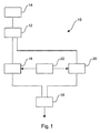
図1は、鉄道車両の圧縮空気ブレーキ装置10を備えたブレーキシステムの有利な一実施形態の非常に簡素化した概略図である。
FIG. 1 is a very simplified schematic of an advantageous embodiment of a braking system including a compressed
ブレーキシステムの圧縮空気ブレーキ装置10は、圧縮器14から供給された圧縮空気を蓄積できる主空気容器12を備えている。圧縮空気は主空気路を介して空気ブレーキアクチュエータ16へ供給される。直通ブレーキの場合には、圧縮空気はブレーキアクチュエータへ直接、制動圧として供給され、自動ブレーキの場合には、主空気路の圧力が弁装置に作用することにより、たとえば補助蓄圧器からブレーキアクチュエータへ制動圧を供給する。
The compressed
図1の実施形態では、圧縮空気ブレーキ装置10は空気ブレーキ装置18と電気指令式空気ブレーキ装置20とを備えている。両ブレーキ装置18,20の構成および動作は、当業者に基本的に公知であるから、ここでは詳細な説明を省略することができる。また、本発明は電気指令式空気ブレーキ装置20ないしは空気ブレーキ装置18のいかなる特定の形式にも限定されない。
In the embodiment of FIG. 1, the compressed
両ブレーキ装置18,20は、圧縮空気ブレーキ装置10の制御部22によって制御される。この制御部22はたとえば、両ブレーキ装置18,20に対応する共通の制御部として構成することができ、または、両方の各ブレーキ装置18,20ごとに別個の2つの制御部として構成することができる。さらに、制御部22はたとえば、ブレーキ装置18,20とは別体に構成することができ、または、ブレーキ装置18,20に統合することができる。また、制御部を電気式/電子式および空気圧式とすることもできる。
Both
本発明は、緊急ブレーキ作動、強制ブレーキ作動または非常ブレーキ作動(すなわち、本発明における「緊急ブレーキ作動」)の場合の、この圧縮空気ブレーキ装置10を備えたブレーキシステムの開ループ制御または閉ループ制御に関する。他の動作状況についてのブレーキシステムの開ループ制御または閉ループ制御は限定されない。すなわち、基本的には任意事項である。
The present invention relates to open-loop control or closed-loop control of a braking system including the compressed
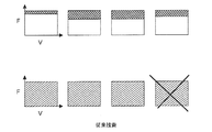
緊急ブレーキ作動の場合のブレーキシステムの本発明の開ループ制御または閉ループ制御方法を、図2および図3に基づいて詳細に説明する。図2は、一例として4車両を有する鉄道車両の場合の本発明の方法を示しているのに対し、図3は比較のため、かかる鉄道車両の場合の従来の制御方法を示している。 The open-loop control or closed-loop control method of the present invention of the braking system in the case of emergency braking operation will be described in detail with reference to FIGS. 2 and 3. FIG. 2 shows the method of the present invention in the case of a railroad vehicle having four vehicles as an example, while FIG. 3 shows a conventional control method in the case of such a railroad vehicle for comparison.
図2および図3の各概略図では、鉄道車両の速度vを横軸として制動圧Fが示されている。同図中、上方の概略図はそれぞれ、認可との関係における制動重量に鑑みた算入可能性を示しているのに対し、下方の概略図はそれぞれ、機能安全性を示している。 In each of the schematic views of FIGS. 2 and 3, the braking pressure F is shown with the speed v of the railway vehicle as the horizontal axis. In the figure, the upper schematics show the possibility of inclusion in view of the braking weight in relation to the approval, while the lower schematics show the functional safety, respectively.
従来のブレーキシステムでは、緊急ブレーキ作動の場合、空気ブレーキ装置または電気指令式空気ブレーキ装置を作動させ、必要な場合には、図3に示されているように電気ダイナミックブレーキ装置によって支援していた。(電気式)空気ブレーキ装置によって調達された制動圧Fは、鉄道車両の複数の各車両ごとに、通常は異なる値で算入され得るので、各車両の制動百分率Brhの特性値を実質的に同一にするためには、電気ダイナミックブレーキ装置も異なる値で算入しなければならない。 In the conventional braking system, in the case of emergency braking, an air braking device or an electric command type air braking device is activated, and when necessary, it is assisted by an electric dynamic braking device as shown in FIG. .. The braking pressure F procured by the (electric) air brake device can usually be included in different values for each of the plurality of rolling stocks of the railcar, so that the characteristic values of the braking percentage Brh of each rolling stock are substantially the same. In order to do so, the electric dynamic braking device must also be included with different values.
機能安全に関しては、従来はたとえば、ブレーキの失陥は4車両のうち最大1車両(一般的には、総数N台のうち最大M台)にのみ可能とすべきことが要請されていた。 Regarding functional safety, for example, it has been required that brake failure should be allowed only for a maximum of 1 vehicle out of 4 vehicles (generally, a maximum of M vehicles out of a total of N vehicles).
図2に示されているように、鉄道車両のブレーキシステムを開ループ制御または閉ループ制御するための本発明の方法では、緊急ブレーキ作動の場合、空気ブレーキ装置18によって(または代替的に電気指令式空気ブレーキ装置20によって)ブレーキアクチュエータ16に対して基本制動圧F0を調達する。図2の実施形態では、この基本制動圧F0は最小制動圧であり、この最小制動圧は少なくとも、鉄道車両の緊急ブレーキ作動中に下回ってはならない制動圧の予め決まった下限値と等しい。 As shown in FIG. 2, in the method of the present invention for open-loop control or closed-loop control of the brake system of a railroad vehicle, in the case of emergency braking, the air brake device 18 (or alternative electric command type) The basic braking pressure F0 is procured for the brake actuator 16 (by the air brake device 20). In the embodiment of FIG. 2, the basic braking pressure F0 is the minimum braking pressure, which is at least equal to a predetermined lower limit of the braking pressure that must not be lowered during the emergency braking operation of the railway vehicle.
緊急ブレーキ作動は、電気指令式空気ブレーキ装置20によって支援される。とりわけ、調達された基本制動圧F0に基づいて電気指令式空気ブレーキ装置20によって、鉄道車両の荷重および/または速度vに依存して制動圧Fを増大させる。
The emergency brake operation is supported by the electric command type
図2に示されているように、有利には、基本制動圧と制動圧増大とから得られる制動圧Fは、電気指令式空気ブレーキ装置20によって緊急ブレーキ作動のために制動重量に鑑みて算入される。
As shown in FIG. 2, advantageously, the braking pressure F obtained from the basic braking pressure and the braking pressure increase is included in consideration of the braking weight for the emergency brake operation by the electric command type
本発明の制御方法でも、機能安全に関して有利には、ブレーキの失陥は総数N台の車両のうち最大M台について可能とすべきことが要請される。 Even in the control method of the present invention, it is required that the failure of the brake should be possible for a maximum of M vehicles out of a total of N vehicles in an advantageous manner in terms of functional safety.
他の一実施形態では、基本制動圧F0は最大制動圧であり、調達された基本制動圧F0に基づいて電気指令式空気ブレーキ装置20によって、鉄道車両の荷重および/または速度vに依存して制動圧Fを減少させる。その際には、得られる制動圧は、制動圧の予め決まった下限値を下回ってはならない。
In another embodiment, the basic braking pressure F0 is the maximum braking pressure, which depends on the load and / or speed v of the rail vehicle by the electric command
10 圧縮空気ブレーキ装置
12 主空気容器
14 圧縮器
16 空気ブレーキアクチュエータ
18 空気ブレーキ装置
20 電気指令式空気ブレーキ装置
22 制御部
F 制動圧、制動重量
F0 基本制動圧
v 速度
10 Compressed
Claims (10)
緊急ブレーキ作動の場合、空気ブレーキ装置(18)は基本制動圧(F0)を調達し、
前記電気指令式空気ブレーキ装置(20)は、調達された前記基本制動圧(F0)に基づいて荷重および/または速度(v)に依存して前記制動圧(F)を変化させる
ことを特徴とする方法。 A brake system including at least an air brake actuator (16), an air brake device (18 ) for generating braking pressure , and an electrically commanded air braking device (20) for generating braking pressure (F). In the method for open-loop control or closed-loop control,
In the case of emergency braking, the air brake device (18) procures the basic braking pressure (F0) and
The electric command type air brake device (20) is characterized in that the braking pressure (F) is changed depending on a load and / or a speed (v) based on the procured basic braking pressure (F0). how to.
調達された前記基本制動圧(F0)に基づいて、前記荷重および/または前記速度(v)に依存して前記制動圧(F)を増大させる、
請求項1記載の方法。 The basic braking pressure (F0) is the minimum braking pressure.
Based on the procured basic braking pressure (F0), the braking pressure (F) is increased depending on the load and / or the speed (v).
The method according to claim 1.
調達された前記基本制動圧(F0)に基づいて、前記荷重および/または前記速度(v)に依存して前記制動圧(F)を減少させる、
請求項1記載の方法。 The basic braking pressure (F0) is the maximum braking pressure.
Based on the procured basic braking pressure (F0), the braking pressure (F) is reduced depending on the load and / or the speed (v).
The method according to claim 1.
請求項1から3までのいずれか1項記載の方法。 The braking pressure (F) does not fall below a predetermined lower limit value during the emergency braking operation.
The method according to any one of claims 1 to 3.
前記制御部(22)は緊急ブレーキ作動時に、前記空気ブレーキ装置(18)が基本制動圧(F0)を調達するように当該空気ブレーキ装置(18)を制御するように構成されており、
前記空気ブレーキ装置(18)によって生成される制動圧(F)は、調達された前記基本制動圧(F0)に基づいて前記電気指令式空気ブレーキ装置(20)によって荷重および/または速度(v)に依存して変化することができる
ことを特徴とするブレーキシステム。 At least an air brake actuator (16), an air brake device (18) for generating a braking pressure (F), an electrically command type air brake device (20) for generating a braking pressure (F), and a control unit. In the brake system provided with (22)
The control unit (22) is configured to control the air brake device (18) so that the air brake device (18) procures a basic braking pressure (F0) when the emergency brake is activated.
The braking pressure (F) generated by the air braking device (18) is a load and / or speed (v) by the electric command type air braking device (20) based on the procured basic braking pressure (F0). A braking system characterized by being able to change depending on.
前記制御部(22)は、前記空気ブレーキ装置(18)または前記電気指令式空気ブレーキ装置(20)によって生成される制動圧(F)を、調達された前記基本制動圧(F0)に基づいて前記荷重および/または前記速度(v)に依存して増大できるように構成されている、
請求項5記載のブレーキシステム。 The basic braking pressure is the minimum braking pressure.
The control unit (22) obtains a braking pressure (F) generated by the air braking device (18) or the electric command type air braking device (20) based on the procured basic braking pressure (F0). It is configured to be able to increase depending on the load and / or the speed (v).
The brake system according to claim 5.
前記制御部(22)は、前記空気ブレーキ装置(18)または前記電気指令式空気ブレーキ装置(20)によって生成される制動圧(F)を、調達された前記基本制動圧(F0)に基づいて前記荷重および/または前記速度(v)に依存して減少できるように構成されている、
請求項5記載のブレーキシステム。 The basic braking pressure is the maximum braking pressure.
The control unit (22) obtains a braking pressure (F) generated by the air braking device (18) or the electric command type air braking device (20) based on the procured basic braking pressure (F0). It is configured so that it can be reduced depending on the load and / or the speed (v).
The brake system according to claim 5.
請求項5から7までのいずれか1項記載のブレーキシステム。 The control unit (22) is configured to control the electric command type air brake device (20) so that the braking pressure (F) does not fall below a predetermined lower limit value during the emergency brake operation.
The brake system according to any one of claims 5 to 7.
請求項5から8までのいずれか1項記載のブレーキシステムを備えていることを特徴とする鉄道車両。 In a rail car having at least one rolling stock with an air brake actuator (16)
A railway vehicle comprising the brake system according to any one of claims 5 to 8.
請求項9記載の鉄道車両。 When the emergency brake is activated, the electric command type air brake device (20) can be included.
The railway vehicle according to claim 9.
Applications Claiming Priority (3)
| Application Number | Priority Date | Filing Date | Title |
|---|---|---|---|
| DE102015120439.8 | 2015-11-25 | ||
| DE102015120439.8A DE102015120439A1 (en) | 2015-11-25 | 2015-11-25 | Method for controlling or regulating a brake system and brake system |
| PCT/EP2016/078329 WO2017089305A1 (en) | 2015-11-25 | 2016-11-21 | Method for controlling or regulating a brake system and brake system |
Publications (3)
| Publication Number | Publication Date |
|---|---|
| JP2018535143A JP2018535143A (en) | 2018-11-29 |
| JP2018535143A5 JP2018535143A5 (en) | 2020-08-06 |
| JP6768802B2 true JP6768802B2 (en) | 2020-10-14 |
Family
ID=57354375
Family Applications (1)
| Application Number | Title | Priority Date | Filing Date |
|---|---|---|---|
| JP2018526932A Active JP6768802B2 (en) | 2015-11-25 | 2016-11-21 | Methods for open-loop or closed-loop control of the braking system, and the braking system |
Country Status (9)
| Country | Link |
|---|---|
| US (1) | US11351972B2 (en) |
| EP (1) | EP3380378B1 (en) |
| JP (1) | JP6768802B2 (en) |
| KR (1) | KR102624360B1 (en) |
| CN (1) | CN108473129B (en) |
| DE (1) | DE102015120439A1 (en) |
| ES (1) | ES2862466T3 (en) |
| PL (1) | PL3380378T3 (en) |
| WO (1) | WO2017089305A1 (en) |
Families Citing this family (6)
| Publication number | Priority date | Publication date | Assignee | Title |
|---|---|---|---|---|
| DE102018129132B3 (en) * | 2018-11-20 | 2020-01-02 | Knorr-Bremse Systeme für Schienenfahrzeuge GmbH | Procedure for determining a braking distance |
| CN110578611B (en) * | 2019-09-29 | 2022-06-28 | 潍柴动力股份有限公司 | Engine brake control system and vehicle |
| CN111169446B (en) * | 2020-01-02 | 2021-04-09 | 中车青岛四方机车车辆股份有限公司 | Rail train's arresting gear and rail train |
| IT202000007003A1 (en) * | 2020-04-02 | 2021-10-02 | Faiveley Transport Italia Spa | Electromechanical service and emergency braking actuator for a railway vehicle and electromechanical braking system |
| KR102503001B1 (en) * | 2021-04-21 | 2023-02-24 | 한국철도기술연구원 | Braking system for trans-continental railway vehicles |
| DE102021214368A1 (en) | 2021-12-15 | 2023-06-15 | Contitech Luftfedersysteme Gmbh | Method for controlling the braking system and braking system of a vehicle |
Family Cites Families (13)
| Publication number | Priority date | Publication date | Assignee | Title |
|---|---|---|---|---|
| DE2801778A1 (en) | 1978-01-17 | 1979-07-19 | Knorr Bremse Gmbh | ELECTRO-PNEUMATIC BRAKE, ESPECIALLY FOR RAIL VEHICLES |
| US4344138A (en) * | 1980-11-05 | 1982-08-10 | Frasier Cline W | Digital air brake control system |
| DE4425789C2 (en) * | 1994-07-21 | 1996-06-13 | Grau Gmbh | Brake system for pneumatically braked trailer vehicles |
| US5984426A (en) | 1997-07-31 | 1999-11-16 | Westinghouse Air Brake Company | Apparatus and method for a railway freight car brake control |
| DE102009042965A1 (en) * | 2009-09-23 | 2011-03-24 | Siemens Aktiengesellschaft | Braking system with intelligent actuator for braking a rail-mounted vehicle |
| DE102009051019A1 (en) * | 2009-10-28 | 2011-05-05 | Knorr-Bremse Systeme für Schienenfahrzeuge GmbH | Emergency braking device of a rail vehicle |
| JP5514653B2 (en) * | 2010-07-05 | 2014-06-04 | 西日本旅客鉄道株式会社 | Brake system for Shinkansen vehicles |
| DE102010053683A1 (en) * | 2010-12-08 | 2012-06-14 | Knorr-Bremse Systeme für Schienenfahrzeuge GmbH | Method for controlling a sliding friction-controlled friction brake system of a rail vehicle |
| DE102011006002A1 (en) | 2011-03-23 | 2012-09-27 | Siemens Aktiengesellschaft | Actuator for a braking system of a rail vehicle |
| DE102011110047A1 (en) * | 2011-08-12 | 2013-02-14 | Knorr-Bremse Systeme für Schienenfahrzeuge GmbH | Emergency brake device for a rail vehicle, brake system for a rail vehicle and rail vehicle |
| DE102012202120A1 (en) | 2012-02-13 | 2013-08-14 | Siemens Aktiengesellschaft | Anti-skid system of a braking device |
| DE102012010519C5 (en) * | 2012-05-25 | 2016-10-20 | Knorr-Bremse Systeme für Schienenfahrzeuge GmbH | Method for controlling a compressed air brake device of a rail vehicle in the case of forced, emergency or emergency braking |
| DE102013224421A1 (en) * | 2013-11-28 | 2015-05-28 | Siemens Aktiengesellschaft | Brake system and method for controlling a brake system |
-
2015
- 2015-11-25 DE DE102015120439.8A patent/DE102015120439A1/en not_active Ceased
-
2016
- 2016-11-21 PL PL16798510T patent/PL3380378T3/en unknown
- 2016-11-21 EP EP16798510.0A patent/EP3380378B1/en active Active
- 2016-11-21 CN CN201680079373.XA patent/CN108473129B/en active Active
- 2016-11-21 JP JP2018526932A patent/JP6768802B2/en active Active
- 2016-11-21 ES ES16798510T patent/ES2862466T3/en active Active
- 2016-11-21 KR KR1020187017645A patent/KR102624360B1/en active IP Right Grant
- 2016-11-21 WO PCT/EP2016/078329 patent/WO2017089305A1/en active Application Filing
- 2016-11-21 US US15/779,441 patent/US11351972B2/en active Active
Also Published As
| Publication number | Publication date |
|---|---|
| EP3380378A1 (en) | 2018-10-03 |
| WO2017089305A1 (en) | 2017-06-01 |
| DE102015120439A1 (en) | 2017-06-01 |
| KR102624360B1 (en) | 2024-01-11 |
| US11351972B2 (en) | 2022-06-07 |
| CN108473129B (en) | 2021-10-01 |
| CN108473129A (en) | 2018-08-31 |
| KR20180085771A (en) | 2018-07-27 |
| ES2862466T3 (en) | 2021-10-07 |
| US20180257623A1 (en) | 2018-09-13 |
| JP2018535143A (en) | 2018-11-29 |
| PL3380378T3 (en) | 2021-06-28 |
| EP3380378B1 (en) | 2021-01-06 |
Similar Documents
| Publication | Publication Date | Title |
|---|---|---|
| JP6768802B2 (en) | Methods for open-loop or closed-loop control of the braking system, and the braking system | |
| JP2018535143A5 (en) | ||
| US8038226B2 (en) | Electropneumatic braking device of a rail vehicle comprising a continuous regulating range | |
| AU2013205185B2 (en) | Park Brake Control Assembly | |
| KR101976237B1 (en) | Method for controlling a compressedair braking device of a rail vehicle in the case of automatic,quick,or emergency braking | |
| AU2017216469B2 (en) | Redundant method of confirming an ecp penalty | |
| EP0856448B1 (en) | Brake pipe sensing unit | |
| CA2363462C (en) | Electronic emergency brake load weigh device | |
| CN102152800B (en) | Wagon brake system | |
| CN110072747B (en) | Intelligent locomotive brake control system | |
| CN112166056B (en) | Control device and method for actuating an actuator for actuating a brake of a vehicle | |
| CN110650875A (en) | Braking device and method for performing emergency braking of a rail vehicle | |
| WO2015064751A1 (en) | Railroad car break system | |
| US11738734B2 (en) | Emergency brake device for a rail vehicle | |
| CN109070854B (en) | Method and device for open-loop or closed-loop control of a brake system | |
| JP2015137028A (en) | Snow resistant braking device for freight car | |
| CN114572174B (en) | Brake control system for railway vehicle | |
| US20180319412A1 (en) | Method for operating a rail vehicle along a railway line | |
| KR20030022706A (en) | Electropneumatic brake system for track car | |
| US20240075911A1 (en) | Electronic pressure control device supplied to a railway brake caliper | |
| EP3747725A1 (en) | Linear braking system for rail vehicles | |
| Whalley | Railway braking systems | |
| AU8872101A (en) | Methods and system for passing signals through a pipe bracket |
Legal Events
| Date | Code | Title | Description |
|---|---|---|---|
| A621 | Written request for application examination |
Free format text: JAPANESE INTERMEDIATE CODE: A621 Effective date: 20180713 |
|
| A977 | Report on retrieval |
Free format text: JAPANESE INTERMEDIATE CODE: A971007 Effective date: 20190722 |
|
| A131 | Notification of reasons for refusal |
Free format text: JAPANESE INTERMEDIATE CODE: A131 Effective date: 20190729 |
|
| A521 | Request for written amendment filed |
Free format text: JAPANESE INTERMEDIATE CODE: A523 Effective date: 20190917 |
|
| A02 | Decision of refusal |
Free format text: JAPANESE INTERMEDIATE CODE: A02 Effective date: 20200212 |
|
| A524 | Written submission of copy of amendment under article 19 pct |
Free format text: JAPANESE INTERMEDIATE CODE: A524 Effective date: 20200611 |
|
| C60 | Trial request (containing other claim documents, opposition documents) |
Free format text: JAPANESE INTERMEDIATE CODE: C60 Effective date: 20200611 |
|
| A911 | Transfer to examiner for re-examination before appeal (zenchi) |
Free format text: JAPANESE INTERMEDIATE CODE: A911 Effective date: 20200624 |
|
| C21 | Notice of transfer of a case for reconsideration by examiners before appeal proceedings |
Free format text: JAPANESE INTERMEDIATE CODE: C21 Effective date: 20200630 |
|
| TRDD | Decision of grant or rejection written | ||
| A01 | Written decision to grant a patent or to grant a registration (utility model) |
Free format text: JAPANESE INTERMEDIATE CODE: A01 Effective date: 20200824 |
|
| A61 | First payment of annual fees (during grant procedure) |
Free format text: JAPANESE INTERMEDIATE CODE: A61 Effective date: 20200923 |
|
| R150 | Certificate of patent or registration of utility model |
Ref document number: 6768802 Country of ref document: JP Free format text: JAPANESE INTERMEDIATE CODE: R150 |
|
| R250 | Receipt of annual fees |
Free format text: JAPANESE INTERMEDIATE CODE: R250 |
|
| R250 | Receipt of annual fees |
Free format text: JAPANESE INTERMEDIATE CODE: R250 |