JP6763386B2 - Image forming device and quality judgment method - Google Patents
Image forming device and quality judgment method Download PDFInfo
- Publication number
- JP6763386B2 JP6763386B2 JP2017530835A JP2017530835A JP6763386B2 JP 6763386 B2 JP6763386 B2 JP 6763386B2 JP 2017530835 A JP2017530835 A JP 2017530835A JP 2017530835 A JP2017530835 A JP 2017530835A JP 6763386 B2 JP6763386 B2 JP 6763386B2
- Authority
- JP
- Japan
- Prior art keywords
- recording
- image
- recording medium
- normal
- defect
- Prior art date
- Legal status (The legal status is an assumption and is not a legal conclusion. Google has not performed a legal analysis and makes no representation as to the accuracy of the status listed.)
- Active
Links
- 238000000034 method Methods 0.000 title claims description 62
- 238000012360 testing method Methods 0.000 claims description 246
- 230000007547 defect Effects 0.000 claims description 223
- 230000015572 biosynthetic process Effects 0.000 claims description 138
- 230000002950 deficient Effects 0.000 claims description 116
- 239000002131 composite material Substances 0.000 claims description 103
- 238000001514 detection method Methods 0.000 claims description 83
- 239000000463 material Substances 0.000 claims description 59
- 238000011084 recovery Methods 0.000 claims description 28
- 238000003860 storage Methods 0.000 claims description 16
- 238000011144 upstream manufacturing Methods 0.000 claims description 16
- 230000007257 malfunction Effects 0.000 claims description 14
- 230000006866 deterioration Effects 0.000 claims description 9
- 238000012937 correction Methods 0.000 claims description 4
- 230000000977 initiatory effect Effects 0.000 claims description 2
- 239000000976 ink Substances 0.000 description 107
- 230000032258 transport Effects 0.000 description 59
- 238000012986 modification Methods 0.000 description 34
- 230000004048 modification Effects 0.000 description 34
- 239000000047 product Substances 0.000 description 34
- 238000012423 maintenance Methods 0.000 description 33
- 238000012546 transfer Methods 0.000 description 29
- 238000005520 cutting process Methods 0.000 description 23
- 230000010485 coping Effects 0.000 description 10
- 238000010586 diagram Methods 0.000 description 9
- 230000000295 complement effect Effects 0.000 description 8
- 238000010438 heat treatment Methods 0.000 description 8
- 238000007689 inspection Methods 0.000 description 7
- 230000002093 peripheral effect Effects 0.000 description 7
- 238000012545 processing Methods 0.000 description 7
- 238000004140 cleaning Methods 0.000 description 6
- 238000003384 imaging method Methods 0.000 description 6
- 230000015654 memory Effects 0.000 description 6
- 238000012805 post-processing Methods 0.000 description 6
- 238000011161 development Methods 0.000 description 3
- 230000018109 developmental process Effects 0.000 description 3
- 239000004744 fabric Substances 0.000 description 3
- 238000010926 purge Methods 0.000 description 3
- 210000000078 claw Anatomy 0.000 description 2
- 239000003086 colorant Substances 0.000 description 2
- 238000004040 coloring Methods 0.000 description 2
- 239000002245 particle Substances 0.000 description 2
- 239000013589 supplement Substances 0.000 description 2
- 238000007796 conventional method Methods 0.000 description 1
- 230000007423 decrease Effects 0.000 description 1
- 238000007599 discharging Methods 0.000 description 1
- 230000000694 effects Effects 0.000 description 1
- 230000012447 hatching Effects 0.000 description 1
- 230000001678 irradiating effect Effects 0.000 description 1
- 239000007788 liquid Substances 0.000 description 1
- 239000004973 liquid crystal related substance Substances 0.000 description 1
- 238000003825 pressing Methods 0.000 description 1
- 239000011347 resin Substances 0.000 description 1
- 229920005989 resin Polymers 0.000 description 1
- 238000005096 rolling process Methods 0.000 description 1
- 239000000126 substance Substances 0.000 description 1
- 230000003936 working memory Effects 0.000 description 1
Images


Classifications
-
- B—PERFORMING OPERATIONS; TRANSPORTING
- B41—PRINTING; LINING MACHINES; TYPEWRITERS; STAMPS
- B41J—TYPEWRITERS; SELECTIVE PRINTING MECHANISMS, i.e. MECHANISMS PRINTING OTHERWISE THAN FROM A FORME; CORRECTION OF TYPOGRAPHICAL ERRORS
- B41J2/00—Typewriters or selective printing mechanisms characterised by the printing or marking process for which they are designed
- B41J2/005—Typewriters or selective printing mechanisms characterised by the printing or marking process for which they are designed characterised by bringing liquid or particles selectively into contact with a printing material
- B41J2/01—Ink jet
- B41J2/135—Nozzles
- B41J2/165—Preventing or detecting of nozzle clogging, e.g. cleaning, capping or moistening for nozzles
- B41J2/16579—Detection means therefor, e.g. for nozzle clogging
-
- B—PERFORMING OPERATIONS; TRANSPORTING
- B41—PRINTING; LINING MACHINES; TYPEWRITERS; STAMPS
- B41J—TYPEWRITERS; SELECTIVE PRINTING MECHANISMS, i.e. MECHANISMS PRINTING OTHERWISE THAN FROM A FORME; CORRECTION OF TYPOGRAPHICAL ERRORS
- B41J2/00—Typewriters or selective printing mechanisms characterised by the printing or marking process for which they are designed
- B41J2/005—Typewriters or selective printing mechanisms characterised by the printing or marking process for which they are designed characterised by bringing liquid or particles selectively into contact with a printing material
- B41J2/01—Ink jet
- B41J2/135—Nozzles
- B41J2/165—Preventing or detecting of nozzle clogging, e.g. cleaning, capping or moistening for nozzles
- B41J2/16585—Preventing or detecting of nozzle clogging, e.g. cleaning, capping or moistening for nozzles for paper-width or non-reciprocating print heads
-
- B—PERFORMING OPERATIONS; TRANSPORTING
- B41—PRINTING; LINING MACHINES; TYPEWRITERS; STAMPS
- B41J—TYPEWRITERS; SELECTIVE PRINTING MECHANISMS, i.e. MECHANISMS PRINTING OTHERWISE THAN FROM A FORME; CORRECTION OF TYPOGRAPHICAL ERRORS
- B41J2/00—Typewriters or selective printing mechanisms characterised by the printing or marking process for which they are designed
- B41J2/005—Typewriters or selective printing mechanisms characterised by the printing or marking process for which they are designed characterised by bringing liquid or particles selectively into contact with a printing material
- B41J2/01—Ink jet
- B41J2/21—Ink jet for multi-colour printing
- B41J2/2132—Print quality control characterised by dot disposition, e.g. for reducing white stripes or banding
- B41J2/2139—Compensation for malfunctioning nozzles creating dot place or dot size errors
-
- B—PERFORMING OPERATIONS; TRANSPORTING
- B41—PRINTING; LINING MACHINES; TYPEWRITERS; STAMPS
- B41J—TYPEWRITERS; SELECTIVE PRINTING MECHANISMS, i.e. MECHANISMS PRINTING OTHERWISE THAN FROM A FORME; CORRECTION OF TYPOGRAPHICAL ERRORS
- B41J2/00—Typewriters or selective printing mechanisms characterised by the printing or marking process for which they are designed
- B41J2/005—Typewriters or selective printing mechanisms characterised by the printing or marking process for which they are designed characterised by bringing liquid or particles selectively into contact with a printing material
- B41J2/01—Ink jet
- B41J2/21—Ink jet for multi-colour printing
- B41J2/2132—Print quality control characterised by dot disposition, e.g. for reducing white stripes or banding
- B41J2/2142—Detection of malfunctioning nozzles
-
- B—PERFORMING OPERATIONS; TRANSPORTING
- B41—PRINTING; LINING MACHINES; TYPEWRITERS; STAMPS
- B41J—TYPEWRITERS; SELECTIVE PRINTING MECHANISMS, i.e. MECHANISMS PRINTING OTHERWISE THAN FROM A FORME; CORRECTION OF TYPOGRAPHICAL ERRORS
- B41J2/00—Typewriters or selective printing mechanisms characterised by the printing or marking process for which they are designed
- B41J2/005—Typewriters or selective printing mechanisms characterised by the printing or marking process for which they are designed characterised by bringing liquid or particles selectively into contact with a printing material
- B41J2/01—Ink jet
- B41J2/21—Ink jet for multi-colour printing
- B41J2/2132—Print quality control characterised by dot disposition, e.g. for reducing white stripes or banding
- B41J2/2146—Print quality control characterised by dot disposition, e.g. for reducing white stripes or banding for line print heads
-
- B—PERFORMING OPERATIONS; TRANSPORTING
- B41—PRINTING; LINING MACHINES; TYPEWRITERS; STAMPS
- B41J—TYPEWRITERS; SELECTIVE PRINTING MECHANISMS, i.e. MECHANISMS PRINTING OTHERWISE THAN FROM A FORME; CORRECTION OF TYPOGRAPHICAL ERRORS
- B41J29/00—Details of, or accessories for, typewriters or selective printing mechanisms not otherwise provided for
- B41J29/38—Drives, motors, controls or automatic cut-off devices for the entire printing mechanism
- B41J29/393—Devices for controlling or analysing the entire machine ; Controlling or analysing mechanical parameters involving printing of test patterns
-
- B—PERFORMING OPERATIONS; TRANSPORTING
- B41—PRINTING; LINING MACHINES; TYPEWRITERS; STAMPS
- B41J—TYPEWRITERS; SELECTIVE PRINTING MECHANISMS, i.e. MECHANISMS PRINTING OTHERWISE THAN FROM A FORME; CORRECTION OF TYPOGRAPHICAL ERRORS
- B41J29/00—Details of, or accessories for, typewriters or selective printing mechanisms not otherwise provided for
- B41J29/46—Applications of alarms, e.g. responsive to approach of end of line
-
- B—PERFORMING OPERATIONS; TRANSPORTING
- B31—MAKING ARTICLES OF PAPER, CARDBOARD OR MATERIAL WORKED IN A MANNER ANALOGOUS TO PAPER; WORKING PAPER, CARDBOARD OR MATERIAL WORKED IN A MANNER ANALOGOUS TO PAPER
- B31B—MAKING CONTAINERS OF PAPER, CARDBOARD OR MATERIAL WORKED IN A MANNER ANALOGOUS TO PAPER
- B31B50/00—Making rigid or semi-rigid containers, e.g. boxes or cartons
- B31B50/74—Auxiliary operations
- B31B50/88—Printing; Embossing
-
- B—PERFORMING OPERATIONS; TRANSPORTING
- B41—PRINTING; LINING MACHINES; TYPEWRITERS; STAMPS
- B41J—TYPEWRITERS; SELECTIVE PRINTING MECHANISMS, i.e. MECHANISMS PRINTING OTHERWISE THAN FROM A FORME; CORRECTION OF TYPOGRAPHICAL ERRORS
- B41J25/00—Actions or mechanisms not otherwise provided for
- B41J2025/008—Actions or mechanisms not otherwise provided for comprising a plurality of print heads placed around a drum
-
- B—PERFORMING OPERATIONS; TRANSPORTING
- B41—PRINTING; LINING MACHINES; TYPEWRITERS; STAMPS
- B41J—TYPEWRITERS; SELECTIVE PRINTING MECHANISMS, i.e. MECHANISMS PRINTING OTHERWISE THAN FROM A FORME; CORRECTION OF TYPOGRAPHICAL ERRORS
- B41J29/00—Details of, or accessories for, typewriters or selective printing mechanisms not otherwise provided for
- B41J29/38—Drives, motors, controls or automatic cut-off devices for the entire printing mechanism
- B41J29/393—Devices for controlling or analysing the entire machine ; Controlling or analysing mechanical parameters involving printing of test patterns
- B41J2029/3935—Devices for controlling or analysing the entire machine ; Controlling or analysing mechanical parameters involving printing of test patterns by means of printed test patterns
Description
本発明は、画像形成装置及び良否判定方法に関する。 The present invention relates to an image forming apparatus and a quality determination method.
従来、画像形成装置の一つとして、インクを吐出するノズルを各々有する複数の記録素子を備え、当該複数の記録素子のノズルから記録媒体に対してインクを吐出することで記録媒体上に画像を形成するインクジェット記録装置が知られている。このインクジェット記録装置では、記録媒体のサイズに比して形成対象の通常画像のサイズが小さい場合には、一の記録媒体に複数の通常画像を割り付けて形成することにより効率的な画像形成を行うことができる。複数の通常画像が形成された後で各通常画像の周囲を裁断することで、一の通常画像が各々形成された複数の記録媒体が取得される。 Conventionally, as one of the image forming devices, a plurality of recording elements each having nozzles for ejecting ink are provided, and an image is output on the recording medium by ejecting ink from the nozzles of the plurality of recording elements to the recording medium. Ink recording devices to be formed are known. In this inkjet recording device, when the size of the normal image to be formed is smaller than the size of the recording medium, efficient image formation is performed by allocating and forming a plurality of normal images on one recording medium. be able to. By cutting the periphery of each normal image after the plurality of normal images are formed, a plurality of recording media on which one normal image is formed are obtained.
インクジェット記録装置では、記録素子の記録動作不良(ノズルからのインク吐出不良)が形成画像の画質の低下に繋がる。これに対し、従来、記録素子を検査して記録素子の記録動作不良を検出する技術がある。
例えば、特許文献1には、記録媒体における通常の画像形成領域外の余白にテスト画像を形成し、このテスト画像を読み取ってその読取結果を解析することにより記録素子の記録動作不良を検出する技術が開示されている。このように記録媒体に通常画像とともに形成されたテスト画像の読取結果から記録動作不良の有無を検出することで、当該記録媒体に形成された通常画像の良否を迅速かつ的確に判定することができる。In an inkjet recording device, a recording operation failure of a recording element (ink ejection failure from a nozzle) leads to deterioration of the image quality of the formed image. On the other hand, conventionally, there is a technique of inspecting a recording element to detect a recording malfunction of the recording element.
For example, Patent Document 1 describes a technique for detecting a recording malfunction of a recording element by forming a test image in a margin outside a normal image forming region on a recording medium, reading the test image, and analyzing the reading result. Is disclosed. By detecting the presence or absence of recording operation failure from the reading result of the test image formed on the recording medium together with the normal image in this way, the quality of the normal image formed on the recording medium can be quickly and accurately determined. ..
しかしながら、上記従来の技術では、テスト画像の読取結果から記録素子の記録動作不良が検出されると、当該記録媒体に形成された通常画像が一括して不良と判定される。このため、一の記録媒体に複数の通常画像が割り付けられて形成されている場合、一部の通常画像が適正に形成されていても当該記録媒体に形成された全ての通常画像が不良と判定されてしまうという課題がある。 However, in the above-mentioned conventional technique, when a recording operation defect of the recording element is detected from the reading result of the test image, the normal images formed on the recording medium are collectively determined to be defective. Therefore, when a plurality of normal images are allocated and formed on one recording medium, it is determined that all the normal images formed on the recording medium are defective even if some of the normal images are properly formed. There is a problem that it will be done.
この発明の目的は、一の記録媒体に対して割り付けがなされた複数の通常画像の各々の良否を容易かつ適切に判定することができる画像形成装置及び良否判定方法を提供することにある。 An object of the present invention is to provide an image forming apparatus and a quality determination method capable of easily and appropriately determining the quality of each of a plurality of ordinary images assigned to one recording medium.
上記目的を達成するため、請求項1に記載の画像形成装置の発明は、
複数の記録素子の記録動作に応じて記録媒体に対して色材を付与する記録手段と、
記録媒体上の一の記録範囲に対して割り付けがなされた複数の形成対象の通常画像とテスト画像とを含む複合画像を前記記録手段により当該記録媒体上に形成させる画像形成制御手段と、
前記記録媒体上に形成された画像を読み取る読取手段と、
前記読取手段により読み取られた前記テスト画像から前記記録素子の記録動作不良を検出する不良検出手段と、
前記不良検出手段による前記記録動作不良の検出結果及び前記複合画像における各画像の配置情報に基づいて前記複数の通常画像各々の良否を判定する判定手段と、
記録媒体と前記記録手段とを一又は二以上の移動方向に相対移動させる移動手段と、
を備え、
前記画像形成制御手段は、所定の一の移動方向に前記相対移動する記録媒体に対して前記記録手段により前記色材を付与させて、前記一の移動方向と直交する幅方向について異なる位置に形成された2以上の前記通常画像と、複数の前記テスト画像とを含む前記複合画像を形成させ、
前記複数のテスト画像は、前記複数の通常画像各々における前記判定の対象となる良否判定対象領域の前記幅方向についての形成範囲と当該通常画像に対応するテスト画像の前記幅方向についての形成範囲とが等しくなるように形成され、
前記判定手段は、前記幅方向について異なる位置に形成された前記2以上の通常画像の良否をそれぞれ判定し、かつ、前記複数の通常画像の各々に対応する前記テスト画像の前記読取手段による読取結果から前記不良検出手段により前記記録動作不良が検出されたか否かに基づいて前記複数の通常画像各々の良否を判定する
ことを特徴としている。
上記目的を達成するため、請求項2に記載の画像形成装置の発明は、
複数の記録素子の記録動作に応じて記録媒体に対して色材を付与する記録手段と、
記録媒体上の一の記録範囲に対して割り付けがなされた複数の形成対象の通常画像とテスト画像とを含む複合画像を前記記録手段により当該記録媒体上に形成させる画像形成制御手段と、
前記記録媒体上に形成された画像を読み取る読取手段と、
前記読取手段により読み取られた前記テスト画像から前記記録素子の記録動作不良を検出する不良検出手段と、
前記不良検出手段による前記記録動作不良の検出結果及び前記複合画像における各画像の配置情報に基づいて前記複数の通常画像各々の良否を判定する判定手段と、
記録媒体と前記記録手段とを一又は二以上の移動方向に相対移動させる移動手段と、
を備え、
前記画像形成制御手段は、所定の一の移動方向に前記相対移動する記録媒体に対して前記記録手段により前記色材を付与させて複数の前記テスト画像を含む前記複合画像を形成させ、
前記複数のテスト画像は、前記複数の通常画像各々における前記判定の対象となる良否判定対象領域の前記一の移動方向と直交する幅方向についての形成範囲と当該通常画像に対応するテスト画像の前記幅方向についての形成範囲とが等しくなるように形成され、
前記判定手段は、前記複数の通常画像の各々に対応する前記テスト画像の前記読取手段による読取結果から前記不良検出手段により前記記録動作不良が検出されたか否かに基づいて前記複数の通常画像各々の良否を判定し、
前記複数の通常画像の各々は、製品の少なくとも一部を構成する画像であって、前記製品の本来の使用態様において前記製品の表面に現れる第1部分と、前記製品の表面に現れない第2部分とを含み、
前記良否判定対象領域は、前記通常画像のうち前記第1部分である
ことを特徴としている。
上記目的を達成するため、請求項3に記載の画像形成装置の発明は、
複数の記録素子の記録動作に応じて記録媒体に対して色材を付与する記録手段と、
記録媒体上の一の記録範囲に対して割り付けがなされた複数の形成対象の通常画像とテスト画像とを含む複合画像を前記記録手段により当該記録媒体上に形成させる画像形成制御手段と、
前記記録媒体上に形成された画像を読み取る読取手段と、
前記読取手段により読み取られた前記テスト画像から前記記録素子の記録動作不良を検出する不良検出手段と、
前記不良検出手段による前記記録動作不良の検出結果及び前記複合画像における各画像の配置情報に基づいて前記複数の通常画像各々の良否を判定する判定手段と、
記録媒体と前記記録手段とを一又は二以上の移動方向に相対移動させる移動手段と、
を備え、
前記画像形成制御手段は、所定の一の移動方向に前記相対移動する記録媒体に対して前記記録手段により前記色材を付与させて複数の前記テスト画像を含む前記複合画像を形成させ、
前記複数のテスト画像は、前記複数の通常画像各々における前記判定の対象となる良否判定対象領域の前記一の移動方向と直交する幅方向についての形成範囲と当該通常画像に対応するテスト画像の前記幅方向についての形成範囲とが等しくなるように形成され、
前記判定手段は、前記複数の通常画像の各々に対応する前記テスト画像の前記読取手段による読取結果から前記不良検出手段により前記記録動作不良が検出されたか否かに基づいて前記複数の通常画像各々の良否を判定し、
前記良否判定対象領域は、前記通常画像の輪郭により定められる
ことを特徴としている。
In order to achieve the above object, the invention of the image forming apparatus according to claim 1 is
A recording means for applying a color material to a recording medium according to the recording operation of a plurality of recording elements,
An image formation control means for forming a composite image including a plurality of normal images to be formed and a test image allocated to one recording range on the recording medium on the recording medium by the recording means.
A reading means for reading an image formed on the recording medium, and
A defect detecting means for detecting a recording operation defect of the recording element from the test image read by the reading means, and a defect detecting means.
A determination means for determining the quality of each of the plurality of normal images based on the detection result of the recording operation defect by the defect detection means and the arrangement information of each image in the composite image.
A moving means for relatively moving the recording medium and the recording means in one or more moving directions,
With
The image forming control means applies the color material to a recording medium that moves relative to a predetermined moving direction by the recording means, and is formed at different positions in a width direction orthogonal to the one moving direction. The composite image including the two or more normal images and the plurality of test images is formed.
The plurality of test images include a formation range in the width direction of the pass / fail judgment target region to be judged in each of the plurality of normal images and a formation range in the width direction of the test image corresponding to the normal image. Formed to be equal,
The determination means determines the quality of the two or more normal images formed at different positions in the width direction , and the reading result of the test image corresponding to each of the plurality of normal images by the reading means. It is characterized in that the quality of each of the plurality of normal images is determined based on whether or not the recording operation defect is detected by the defect detecting means .
In order to achieve the above object, the invention of the image forming apparatus according to
A recording means for applying a color material to a recording medium according to the recording operation of a plurality of recording elements,
An image formation control means for forming a composite image including a plurality of normal images to be formed and a test image allocated to one recording range on the recording medium on the recording medium by the recording means.
A reading means for reading an image formed on the recording medium, and
A defect detecting means for detecting a recording operation defect of the recording element from the test image read by the reading means, and a defect detecting means.
A determination means for determining the quality of each of the plurality of normal images based on the detection result of the recording operation defect by the defect detection means and the arrangement information of each image in the composite image.
A moving means for relatively moving the recording medium and the recording means in one or more moving directions,
With
The image formation control means applies the color material to the recording medium that moves relative to a predetermined movement direction by the recording means to form the composite image including the plurality of test images.
The plurality of test images are the formation range in the width direction orthogonal to the one movement direction of the pass / fail judgment target region to be judged in each of the plurality of normal images, and the test image corresponding to the normal image. It is formed so that it is equal to the formation range in the width direction.
The determination means is based on whether or not the recording operation defect is detected by the defect detecting means from the reading result of the test image corresponding to each of the plurality of normal images by the reading means. Judging the quality of
Each of the plurality of normal images is an image constituting at least a part of the product, and the first portion that appears on the surface of the product in the original usage mode of the product and the second portion that does not appear on the surface of the product. Including parts
The pass / fail determination target region is characterized in that it is the first portion of the normal image.
In order to achieve the above object, the invention of the image forming apparatus according to claim 3 is
A recording means for applying a color material to a recording medium according to the recording operation of a plurality of recording elements,
An image formation control means for forming a composite image including a plurality of normal images to be formed and a test image allocated to one recording range on the recording medium on the recording medium by the recording means.
A reading means for reading an image formed on the recording medium, and
A defect detecting means for detecting a recording operation defect of the recording element from the test image read by the reading means, and a defect detecting means.
A determination means for determining the quality of each of the plurality of normal images based on the detection result of the recording operation defect by the defect detection means and the arrangement information of each image in the composite image.
A moving means for relatively moving the recording medium and the recording means in one or more moving directions,
With
The image formation control means applies the color material to the recording medium that moves relative to a predetermined movement direction by the recording means to form the composite image including the plurality of test images.
The plurality of test images are the formation range in the width direction orthogonal to the one movement direction of the pass / fail judgment target region to be judged in each of the plurality of normal images, and the test image corresponding to the normal image. It is formed so that it is equal to the formation range in the width direction.
The determination means is based on whether or not the recording operation defect is detected by the defect detecting means from the reading result of the test image corresponding to each of the plurality of normal images by the reading means. Judging the quality of
The pass / fail judgment target area is characterized in that it is determined by the contour of the normal image.
請求項4に記載の発明は、請求項1に記載の画像形成装置において、
前記良否判定対象領域は、前記通常画像の輪郭により定められることを特徴としている。
請求項5に記載の発明は、請求項1に記載の画像形成装置において、
前記複数の通常画像の各々は、製品の少なくとも一部を構成する画像であり、
前記良否判定対象領域は、前記通常画像のうち前記製品の本来の使用態様において前記製品の表面に現れる部分に対応する領域である
ことを特徴としている。
The invention described in請Motomeko 4, in the image forming apparatus according to claim 1,
The pass / fail judgment target area is characterized in that it is determined by the contour of the normal image.
The invention according to claim 5 is the image forming apparatus according to claim 1 .
Each of the plurality of normal images is an image that constitutes at least a part of the product.
The pass / fail judgment target region is characterized in that it is a region corresponding to a portion of the normal image that appears on the surface of the product in the original usage mode of the product.
請求項6に記載の発明は、請求項1〜5のいずれか一項に記載の画像形成装置において、
前記画像形成制御手段は、前記記録手段により前記複数の通常画像の各々と個別に対応する前記テスト画像をそれぞれ形成させることを特徴としている。
The invention according to claim 6 is the image forming apparatus according to any one of claims 1 to 5 .
The image formation control means is characterized in that the recording means forms the test image individually corresponding to each of the plurality of normal images.
請求項7に記載の発明は、請求項1〜6のいずれか一項に記載の画像形成装置において、
前記画像形成制御手段は、前記記録手段により、前記通常画像よりも当該通常画像に各々対応するテスト画像を前記記録手段に対する当該記録媒体の前記一の移動方向について前記色材が付与されるタイミングが相対的に遅い上流側に形成させることを特徴としている。
The invention according to claim 7 is the image forming apparatus according to any one of claims 1 to 6 .
In the image formation control means, the timing at which the color material is applied by the recording means to the test image corresponding to the normal image rather than the normal image in the one moving direction of the recording medium with respect to the recording means is set. It is characterized by being formed on the relatively slow upstream side.
請求項8に記載の発明は、請求項7に記載の画像形成装置において、
前記画像形成制御手段は、前記複数の通常画像が前記一の移動方向について異なる位置に形成される場合に、前記記録手段により、一の通常画像に対応するテスト画像を、当該一の通常画像に対して前記上流側に形成される他の通常画像よりも下流側に形成させることを特徴としている。
上記目的を達成するため、請求項9に記載の画像形成装置の発明は、
複数の記録素子の記録動作に応じて記録媒体に対して色材を付与する記録手段と、
記録媒体上の一の記録範囲に対して割り付けがなされた複数の形成対象の通常画像とテスト画像とを含む複合画像を前記記録手段により当該記録媒体上に形成させる画像形成制御手段と、
前記記録媒体上に形成された画像を読み取る読取手段と、
前記読取手段により読み取られた前記テスト画像から前記記録素子の記録動作不良を検出する不良検出手段と、
前記不良検出手段による前記記録動作不良の検出結果及び前記複合画像における各画像の配置情報に基づいて前記複数の通常画像各々の良否を判定する判定手段と、
記録媒体と前記記録手段とを一又は二以上の移動方向に相対移動させる移動手段と、
前記複数の通常画像各々における前記判定の対象となる良否判定対象領域の配置を示す良否判定対象領域情報を記憶する記憶手段と、
を備え、
前記画像形成制御手段は、所定の一の移動方向に前記相対移動する記録媒体に対して前記記録手段により前記色材を付与させて前記複合画像を形成させ、
前記テスト画像は、前記一の移動方向と直交する幅方向について、前記複数の通常画像の各々のうち前記良否判定対象領域の形成範囲を少なくとも含むように形成され、
前記判定手段は、前記不良検出手段により検出された前記記録動作不良に係る不良記録素子の位置及び前記良否判定対象領域情報に基づいて前記複数の通常画像各々の良否を判定し、
前記複数の通常画像の各々は、製品の少なくとも一部を構成する画像であって、前記製品の本来の使用態様において前記製品の表面に現れる第1部分と、前記製品の表面に現れない第2部分とを含み、
前記良否判定対象領域は、前記通常画像のうち前記第1部分である
ことを特徴としている。
上記目的を達成するため、請求項10に記載の画像形成装置の発明は、
複数の記録素子の記録動作に応じて記録媒体に対して色材を付与する記録手段と、
記録媒体上の一の記録範囲に対して割り付けがなされた複数の形成対象の通常画像とテスト画像とを含む複合画像を前記記録手段により当該記録媒体上に形成させる画像形成制御手段と、
前記記録媒体上に形成された画像を読み取る読取手段と、
前記読取手段により読み取られた前記テスト画像から前記記録素子の記録動作不良を検出する不良検出手段と、
前記不良検出手段による前記記録動作不良の検出結果及び前記複合画像における各画像の配置情報に基づいて前記複数の通常画像各々の良否を判定する判定手段と、
記録媒体と前記記録手段とを一又は二以上の移動方向に相対移動させる移動手段と、
前記複数の通常画像各々における前記判定の対象となる良否判定対象領域の配置を示す良否判定対象領域情報を記憶する記憶手段と、
を備え、
前記画像形成制御手段は、所定の一の移動方向に前記相対移動する記録媒体に対して前記記録手段により前記色材を付与させて前記複合画像を形成させ、
前記テスト画像は、前記一の移動方向と直交する幅方向について、前記複数の通常画像の各々のうち前記良否判定対象領域の形成範囲を少なくとも含むように形成され、
前記判定手段は、前記不良検出手段により検出された前記記録動作不良に係る不良記録素子の位置及び前記良否判定対象領域情報に基づいて前記複数の通常画像各々の良否を判定し、
前記良否判定対象領域は、前記通常画像の輪郭により定められる
ことを特徴としている。
The invention according to claim 8 is the image forming apparatus according to claim 7 .
When the plurality of normal images are formed at different positions in the one moving direction, the image forming control means converts a test image corresponding to the one normal image into the one normal image by the recording means. On the other hand, it is characterized in that it is formed on the downstream side of the other normal images formed on the upstream side.
In order to achieve the above object, the invention of the image forming apparatus according to claim 9 is
A recording means for applying a color material to a recording medium according to the recording operation of a plurality of recording elements,
An image formation control means for forming a composite image including a plurality of normal images to be formed and a test image allocated to one recording range on the recording medium on the recording medium by the recording means.
A reading means for reading an image formed on the recording medium, and
A defect detecting means for detecting a recording operation defect of the recording element from the test image read by the reading means, and a defect detecting means.
A determination means for determining the quality of each of the plurality of normal images based on the detection result of the recording operation defect by the defect detection means and the arrangement information of each image in the composite image.
A moving means for relatively moving the recording medium and the recording means in one or more moving directions,
A storage means for storing information on a pass / fail judgment target area indicating the arrangement of a pass / fail judgment target area to be determined in each of the plurality of normal images.
With
The image formation control means applies the color material to a recording medium that moves relative to a predetermined movement direction by the recording means to form the composite image.
The test image is formed so as to include at least the formation range of the quality determination target region of each of the plurality of normal images in the width direction orthogonal to the one movement direction.
The determination means determines the quality of each of the plurality of normal images based on the position of the defect recording element related to the recording operation defect detected by the defect detection means and the quality determination target area information.
Each of the plurality of normal images is an image constituting at least a part of the product, and the first portion that appears on the surface of the product in the original usage mode of the product and the second portion that does not appear on the surface of the product. Including parts
The pass / fail determination target region is characterized in that it is the first portion of the normal image.
In order to achieve the above object, the invention of the image forming apparatus according to claim 10 is
A recording means for applying a color material to a recording medium according to the recording operation of a plurality of recording elements,
An image formation control means for forming a composite image including a plurality of normal images to be formed and a test image allocated to one recording range on the recording medium on the recording medium by the recording means.
A reading means for reading an image formed on the recording medium, and
A defect detecting means for detecting a recording operation defect of the recording element from the test image read by the reading means, and a defect detecting means.
A determination means for determining the quality of each of the plurality of normal images based on the detection result of the recording operation defect by the defect detection means and the arrangement information of each image in the composite image.
A moving means for relatively moving the recording medium and the recording means in one or more moving directions,
A storage means for storing information on a pass / fail judgment target area indicating the arrangement of a pass / fail judgment target area to be determined in each of the plurality of normal images.
With
The image formation control means applies the color material to a recording medium that moves relative to a predetermined movement direction by the recording means to form the composite image.
The test image is formed so as to include at least the formation range of the quality determination target region of each of the plurality of normal images in the width direction orthogonal to the one movement direction.
The determination means determines the quality of each of the plurality of normal images based on the position of the defect recording element related to the recording operation defect detected by the defect detection means and the quality determination target area information.
The pass / fail judgment target area is characterized in that it is determined by the contour of the normal image.
上記目的を達成するため、請求項11に記載の画像形成装置の発明は、
複数の記録素子の記録動作に応じて記録媒体に対して色材を付与する記録手段と、
記録媒体上の一の記録範囲に対して割り付けがなされた複数の形成対象の通常画像とテスト画像とを含む複合画像を前記記録手段により当該記録媒体上に形成させる画像形成制御手段と、
前記記録媒体上に形成された画像を読み取る読取手段と、
前記読取手段により読み取られた前記テスト画像から前記記録素子の記録動作不良を検出する不良検出手段と、
前記不良検出手段による前記記録動作不良の検出結果及び前記複合画像における各画像の配置情報に基づいて前記複数の通常画像各々の良否を判定する判定手段と、
記録媒体と前記記録手段とを一又は二以上の移動方向に相対移動させる移動手段と、
前記複数の通常画像各々における前記判定の対象となる良否判定対象領域の配置を示す良否判定対象領域情報を記憶する記憶手段と、
を備え、
前記画像形成制御手段は、所定の一の移動方向に前記相対移動する記録媒体に対して前記記録手段により前記色材を付与させて、前記一の移動方向と直交する幅方向について異なる位置に形成された2以上の前記通常画像を含む前記複合画像を形成させ、
前記テスト画像は、前記幅方向について、前記複数の通常画像の各々のうち前記良否判定対象領域の形成範囲を少なくとも含むように形成され、
前記判定手段は、前記幅方向について異なる位置に形成された前記2以上の通常画像の良否をそれぞれ判定し、かつ、前記不良検出手段により検出された前記記録動作不良に係る不良記録素子の位置及び前記良否判定対象領域情報に基づいて前記複数の通常画像各々の良否を判定する
ことを特徴としている。
請求項12に記載の発明は、請求項11に記載の画像形成装置において、
前記良否判定対象領域は、前記通常画像の輪郭により定められることを特徴としている。
請求項13に記載の発明は、請求項11に記載の画像形成装置において、
前記複数の通常画像の各々は、製品の少なくとも一部を構成する画像であり、
前記良否判定対象領域は、前記通常画像のうち前記製品の本来の使用態様において前記製品の表面に現れる部分に対応する領域である
ことを特徴としている。
In order to achieve the above object, the invention of the image forming apparatus according to claim 11 is
A recording means for applying a color material to a recording medium according to the recording operation of a plurality of recording elements,
An image formation control means for forming a composite image including a plurality of normal images to be formed and a test image allocated to one recording range on the recording medium on the recording medium by the recording means.
A reading means for reading an image formed on the recording medium, and
A defect detecting means for detecting a recording operation defect of the recording element from the test image read by the reading means, and a defect detecting means.
A determination means for determining the quality of each of the plurality of normal images based on the detection result of the recording operation defect by the defect detection means and the arrangement information of each image in the composite image.
A moving means for relatively moving the recording medium and the recording means in one or more moving directions,
Storage means for storing the quality determination target region information indicating the arrangement of the quality determination target region of interest of the determination in the plurality of normal images each,
With
The image forming control means applies the color material to a recording medium that moves relative to a predetermined moving direction by the recording means, and is formed at different positions in a width direction orthogonal to the one moving direction. The composite image including the two or more normal images formed therein is formed.
The test image is formed so as to include at least the formation range of the quality determination target region in each of the plurality of normal images in the width direction.
The determination means determines the quality of the two or more normal images formed at different positions in the width direction, and the position of the defect recording element related to the recording operation defect detected by the defect detection means and the position of the defect recording element. It is characterized in that the quality of each of the plurality of normal images is determined based on the quality determination target area information.
The invention according to claim 12 is the image forming apparatus according to claim 11 .
The pass / fail judgment target area is characterized in that it is determined by the contour of the normal image.
The invention according to claim 13 is the image forming apparatus according to claim 11 .
Each of the plurality of normal images is an image that constitutes at least a part of the product.
The pass / fail judgment target region is characterized in that it is a region corresponding to a portion of the normal image that appears on the surface of the product in the original usage mode of the product.
請求項14に記載の発明は、請求項9〜13のいずれか一項に記載の画像形成装置において、
前記画像形成制御手段は、前記記録手段により、前記複数の通常画像よりも前記テスト画像を前記記録手段に対する当該記録媒体の前記一の移動方向について前記色材が付与されるタイミングが相対的に遅い上流側に形成させることを特徴としている。
The invention according to claim 14 is the image forming apparatus according to any one of claims 9 to 13 .
In the image formation control means, the timing at which the color material is applied to the test image by the recording means in the one moving direction of the recording medium with respect to the recording means is relatively later than that of the plurality of normal images. It is characterized by being formed on the upstream side.
請求項15に記載の発明は、請求項14に記載の画像形成装置において、
前記画像形成制御手段は、前記記録手段により前記記録媒体上に前記テスト画像を複数形成させ、
前記複合画像は、前記複数の通常画像のうち少なくとも一の通常画像が他の何れかの通常画像に対応する前記テスト画像に対して前記上流側に形成される
ことを特徴としている。
The invention according to claim 15 is the image forming apparatus according to claim 14 .
In the image formation control means, a plurality of the test images are formed on the recording medium by the recording means.
The composite image is characterized in that at least one of the plurality of normal images is formed on the upstream side of the test image corresponding to any of the other normal images.
上記目的を達成するため、請求項16に記載の画像形成装置の発明は、
複数の記録素子の記録動作に応じて記録媒体に対して色材を付与する記録手段と、
記録媒体上の一の記録範囲に対して割り付けがなされた複数の形成対象の通常画像とテスト画像とを含む複合画像を前記記録手段により当該記録媒体上に形成させる画像形成制御手段と、
前記記録媒体上に形成された画像を読み取る読取手段と、
前記読取手段により読み取られた前記テスト画像から前記記録素子の記録動作不良を検出する不良検出手段と、
前記不良検出手段による前記記録動作不良の検出結果及び前記複合画像における各画像の配置情報に基づいて前記複数の通常画像各々の良否を判定する判定手段と、
記録媒体と前記記録手段とを一又は二以上の移動方向に相対移動させる移動手段と、
を備え、
前記画像形成制御手段は、所定の一の移動方向に前記相対移動する記録媒体に対して前記記録手段により前記色材を付与させて、前記一の移動方向と直交する幅方向について異なる位置に形成された2以上の前記通常画像を含む前記複合画像を形成させ、
前記判定手段は、前記幅方向について異なる位置に形成された前記2以上の通常画像の良否をそれぞれ判定し、
前記画像形成制御手段は、記録媒体上に形成され前記判定手段により不良と判定された通常画像を他の記録媒体上に適正に形成する再形成動作を前記記録手段により行わせる
ことを特徴としている。
In order to achieve the above object, the invention of the image forming apparatus according to claim 16 is
A recording means for applying a color material to a recording medium according to the recording operation of a plurality of recording elements,
An image formation control means for forming a composite image including a plurality of normal images to be formed and a test image allocated to one recording range on the recording medium on the recording medium by the recording means.
A reading means for reading an image formed on the recording medium, and
A defect detecting means for detecting a recording operation defect of the recording element from the test image read by the reading means, and a defect detecting means.
A determination means for determining the quality of each of the plurality of normal images based on the detection result of the recording operation defect by the defect detection means and the arrangement information of each image in the composite image.
A moving means for relatively moving the recording medium and the recording means in one or more moving directions,
With
The image forming control means applies the color material to a recording medium that moves relative to a predetermined moving direction by the recording means, and is formed at different positions in a width direction orthogonal to the one moving direction. The composite image including the two or more normal images formed therein is formed.
The determination means determines the quality of the two or more normal images formed at different positions in the width direction, respectively.
The image formation control means is characterized in that the recording means performs a reshaping operation of appropriately forming a normal image formed on a recording medium and determined to be defective by the determination means on another recording medium. ..
請求項17に記載の発明は、請求項16に記載の画像形成装置において、
前記画像形成制御手段は、記録媒体上に形成された複数の同一の通常画像が前記判定手段により不良と判定された場合に、不良と判定された数の当該通常画像が他の記録媒体上に形成されるように前記記録手段により前記再形成動作を行わせることを特徴としている。
The invention according to claim 17 is the image forming apparatus according to claim 16 .
In the image formation control means, when a plurality of the same normal images formed on the recording medium are determined to be defective by the determination means, the number of the normal images determined to be defective is placed on the other recording medium. It is characterized in that the reshaping operation is performed by the recording means so as to be formed.
上記目的を達成するため、請求項18に記載の画像形成装置の発明は、
複数の記録素子の記録動作に応じて記録媒体に対して色材を付与する記録手段と、
記録媒体上の一の記録範囲に対して割り付けがなされた複数の形成対象の通常画像とテスト画像とを含む複合画像を前記記録手段により当該記録媒体上に形成させる画像形成制御手段と、
前記記録媒体上に形成された画像を読み取る読取手段と、
前記読取手段により読み取られた前記テスト画像から前記記録素子の記録動作不良を検出する不良検出手段と、
前記不良検出手段による前記記録動作不良の検出結果及び前記複合画像における各画像の配置情報に基づいて前記複数の通常画像各々の良否を判定する判定手段と、
記録媒体と前記記録手段とを一又は二以上の移動方向に相対移動させる移動手段と、
を備え、
前記画像形成制御手段は、所定の一の移動方向に前記相対移動する記録媒体に対して前記記録手段により前記色材を付与させて、前記一の移動方向と直交する幅方向について異なる位置に形成された2以上の前記通常画像を含む前記複合画像を形成させ、
前記判定手段は、前記幅方向について異なる位置に形成された前記2以上の通常画像の良否をそれぞれ判定し、
前記画像形成制御手段は、前記不良検出手段により前記記録動作不良が検出された場合に、前記記録手段により前記記録動作不良に係る不良記録素子を同定するための同定用画像を当該記録媒体上に形成させ、
前記読取手段により読み取られた前記同定用画像から前記不良記録素子を同定する不良記録素子同定手段を備え、
前記画像形成制御手段は、前記不良記録素子が同定された場合に、前記不良記録素子及び当該不良記録素子の周辺の前記記録素子による記録動作を調整することで当該不良記録素子の記録動作不良を補完した前記複合画像を前記記録手段により形成させる
ことを特徴としている。
In order to achieve the above object, the invention of the image forming apparatus according to claim 18 is
A recording means for applying a color material to a recording medium according to the recording operation of a plurality of recording elements,
An image formation control means for forming a composite image including a plurality of normal images to be formed and a test image allocated to one recording range on the recording medium on the recording medium by the recording means.
A reading means for reading an image formed on the recording medium, and
A defect detecting means for detecting a recording operation defect of the recording element from the test image read by the reading means, and a defect detecting means.
A determination means for determining the quality of each of the plurality of normal images based on the detection result of the recording operation defect by the defect detection means and the arrangement information of each image in the composite image.
A moving means for relatively moving the recording medium and the recording means in one or more moving directions,
With
The image forming control means applies the color material to a recording medium that moves relative to a predetermined moving direction by the recording means, and is formed at different positions in a width direction orthogonal to the one moving direction. The composite image including the two or more normal images formed therein is formed.
The determination means determines the quality of the two or more normal images formed at different positions in the width direction, respectively.
When the defect detecting means detects the recording operation defect, the image forming control means displays an identification image on the recording medium for identifying the defective recording element related to the recording operation defect by the recording means. Form and
Comprising a defective recording element identifying means for identifying the defective recording element from the identifying image read by the pre-Symbol reading means,
When the defective recording element is identified, the image forming control means adjusts the recording operation by the defective recording element and the recording element around the defective recording element to prevent the defective recording element from recording operation failure. It is characterized in that the complemented composite image is formed by the recording means.
請求項19に記載の発明は、請求項18に記載の画像形成装置において、
前記不良記録素子が同定された場合に、当該不良記録素子及び当該不良記録素子の周辺の前記記録素子による記録動作を調整し、当該不良記録素子の記録動作不良が補完されるように前記複合画像に係る画像データを補正する補正手段を備えることを特徴としている。
The invention according to claim 19 is the image forming apparatus according to claim 18 .
When the defective recording element is identified, the composite image is adjusted so that the recording operation of the defective recording element and the recording element around the defective recording element is adjusted so that the recording operation defect of the defective recording element is complemented. It is characterized by providing a correction means for correcting the image data according to the above.
上記目的を達成するため、請求項20に記載の画像形成装置の発明は、
複数の記録素子の記録動作に応じて記録媒体に対して色材を付与する記録手段と、
記録媒体上の一の記録範囲に対して割り付けがなされた複数の形成対象の通常画像とテスト画像とを含む複合画像を前記記録手段により当該記録媒体上に形成させる画像形成制御手段と、
前記記録媒体上に形成された画像を読み取る読取手段と、
前記読取手段により読み取られた前記テスト画像から前記記録素子の記録動作不良を検出する不良検出手段と、
前記不良検出手段による前記記録動作不良の検出結果及び前記複合画像における各画像の配置情報に基づいて前記複数の通常画像各々の良否を判定する判定手段と、
記録媒体と前記記録手段とを一又は二以上の移動方向に相対移動させる移動手段と、
前記記録動作不良の前記記録素子のうち正常な記録動作を行う正常状態に回復可能な記録素子を当該正常状態に回復させ得る回復動作を行う回復手段と、
前記不良検出手段により検出された前記記録素子の記録動作不良が形成画像の画質の劣化に係る所定の条件を満たす場合に、前記回復手段による前記回復動作を開始させる回復制御手段と、
を備え、
前記画像形成制御手段は、所定の一の移動方向に前記相対移動する記録媒体に対して前記記録手段により前記色材を付与させて、前記一の移動方向と直交する幅方向について異なる位置に形成された2以上の前記通常画像を含む前記複合画像を形成させ、
前記判定手段は、前記幅方向について異なる位置に形成された前記2以上の通常画像の良否をそれぞれ判定する
ことを特徴としている。
In order to achieve the above object, the invention of the image forming apparatus according to claim 20 is
A recording means for applying a color material to a recording medium according to the recording operation of a plurality of recording elements,
An image formation control means for forming a composite image including a plurality of normal images to be formed and a test image allocated to one recording range on the recording medium on the recording medium by the recording means.
A reading means for reading an image formed on the recording medium, and
A defect detecting means for detecting a recording operation defect of the recording element from the test image read by the reading means, and a defect detecting means.
A determination means for determining the quality of each of the plurality of normal images based on the detection result of the recording operation defect by the defect detection means and the arrangement information of each image in the composite image.
A moving means for relatively moving the recording medium and the recording means in one or more moving directions,
A recovery means for performing a recovery operation capable of recovering a recording element capable of recovering to a normal state, which performs a normal recording operation, among the recording elements having a poor recording operation,
When a predetermined condition is satisfied in accordance with the deterioration of the quality of the recorded malfunctions forms images of the detected said recording element by the defect detection means, and recovery control means for starting the recovery operation by the recovery means,
With
The image forming control means applies the color material to a recording medium that moves relative to a predetermined moving direction by the recording means, and is formed at different positions in a width direction orthogonal to the one moving direction. The composite image including the two or more normal images formed therein is formed.
The determination means is characterized in that it determines the quality of the two or more normal images formed at different positions in the width direction .
請求項21に記載の発明は、請求項16又は17に記載の画像形成装置において、
前記記録動作不良の前記記録素子のうち正常な記録動作を行う正常状態に回復可能な記録素子を当該正常状態に回復させ得る回復動作を行う回復手段と、
前記不良検出手段により検出された前記記録素子の記録動作不良が形成画像の画質の劣化に係る所定の条件を満たす場合に、前記回復手段による前記回復動作を開始させる回復制御手段と
を備え、
前記画像形成制御手段は、前記回復動作の開始前に前記判定手段により不良と判定された通常画像に係る前記再形成動作を当該回復動作が行われた後に前記記録手段により行わせる
ことを特徴としている。
The invention according to claim 21 is the image forming apparatus according to claim 16 or 17 .
A recovery means for performing a recovery operation capable of recovering a recording element capable of recovering to a normal state, which performs a normal recording operation, among the recording elements having a poor recording operation,
A recovery control means for initiating the recovery operation by the recovery means when the recording operation failure of the recording element detected by the defect detecting means satisfies a predetermined condition relating to deterioration of the image quality of the formed image.
The image formation control means is characterized in that the reshaping operation related to a normal image determined to be defective by the determination means is performed by the recording means after the recovery operation is performed before the start of the recovery operation. There is.
上記目的を達成するため、請求項22に記載の良否判定方法の発明は、
複数の記録素子の記録動作に応じて記録媒体に対して色材を付与する記録手段と、記録媒体と前記記録手段とを一又は二以上の移動方向に相対移動させる移動手段と、を備える画像形成装置により形成された画像の良否を判定する良否判定方法であって、
記録媒体上の一の記録範囲に対して割り付けがなされた複数の形成対象の通常画像とテスト画像とを含む複合画像を前記記録手段により当該記録媒体上に形成させる画像形成ステップ、
画像を読み取る読取手段により読み取られた前記テスト画像から前記記録素子の記録動作不良を検出する不良検出ステップ、
前記不良検出ステップによる前記記録動作不良の検出結果及び前記複合画像における各画像の配置情報に基づいて前記複数の通常画像各々の良否を判定する判定ステップ
を含み、
前記画像形成ステップでは、所定の一の移動方向に前記相対移動する記録媒体に対して前記記録手段により前記色材を付与させて複数の前記テスト画像を含む前記複合画像を形成させ、
前記画像形成ステップでは、前記複数のテスト画像を、前記複数の通常画像各々における前記判定の対象となる良否判定対象領域の前記一の移動方向と直交する幅方向についての形成範囲と当該通常画像に対応するテスト画像の前記幅方向についての形成範囲とが等しくなるように形成させ、
前記判定ステップでは、前記複数の通常画像の各々に対応する前記テスト画像の前記読取手段による読取結果から前記不良検出ステップにおいて前記記録動作不良が検出されたか否かに基づいて前記複数の通常画像各々の良否を判定し、
前記複数の通常画像の各々は、製品の少なくとも一部を構成する画像であって、前記製品の本来の使用態様において前記製品の表面に現れる第1部分と、前記製品の表面に現れない第2部分とを含み、
前記良否判定対象領域は、前記通常画像のうち前記第1部分である
ことを特徴としている。
また、上記目的を達成するため、請求項23に記載の良否判定方法の発明は、
複数の記録素子の記録動作に応じて記録媒体に対して色材を付与する記録手段と、記録媒体と前記記録手段とを一又は二以上の移動方向に相対移動させる移動手段と、を備える画像形成装置により形成された画像の良否を判定する良否判定方法であって、
記録媒体上の一の記録範囲に対して割り付けがなされた複数の形成対象の通常画像とテスト画像とを含む複合画像を前記記録手段により当該記録媒体上に形成させる画像形成ステップ、
画像を読み取る読取手段により読み取られた前記テスト画像から前記記録素子の記録動作不良を検出する不良検出ステップ、
前記不良検出ステップによる前記記録動作不良の検出結果及び前記複合画像における各画像の配置情報に基づいて前記複数の通常画像各々の良否を判定する判定ステップ
を含み、
前記画像形成ステップでは、所定の一の移動方向に前記相対移動する記録媒体に対して前記記録手段により前記色材を付与させて複数の前記テスト画像を含む前記複合画像を形成させ、
前記画像形成ステップでは、前記複数のテスト画像を、前記複数の通常画像各々における前記判定の対象となる良否判定対象領域の前記一の移動方向と直交する幅方向についての形成範囲と当該通常画像に対応するテスト画像の前記幅方向についての形成範囲とが等しくなるように形成させ、
前記判定ステップでは、前記複数の通常画像の各々に対応する前記テスト画像の前記読取手段による読取結果から前記不良検出ステップにおいてにより前記記録動作不良が検出されたか否かに基づいて前記複数の通常画像各々の良否を判定し、
前記良否判定対象領域は、前記通常画像の輪郭により定められる
ことを特徴としている。
また、上記目的を達成するため、請求項24に記載の良否判定方法の発明は、
複数の記録素子の記録動作に応じて記録媒体に対して色材を付与する記録手段と、記録媒体と前記記録手段とを一又は二以上の移動方向に相対移動させる移動手段と、を備える画像形成装置により形成された画像の良否を判定する良否判定方法であって、
記録媒体上の一の記録範囲に対して割り付けがなされた複数の形成対象の通常画像とテスト画像とを含む複合画像を前記記録手段により当該記録媒体上に形成させる画像形成ステップ、
画像を読み取る読取手段により読み取られた前記テスト画像から前記記録素子の記録動作不良を検出する不良検出ステップ、
前記不良検出ステップによる前記記録動作不良の検出結果及び前記複合画像における各画像の配置情報に基づいて前記複数の通常画像各々の良否を判定する判定ステップ
を含み、
前記画像形成ステップでは、所定の一の移動方向に前記相対移動する記録媒体に対して前記記録手段により前記色材を付与させて前記複合画像を形成させ、
前記画像形成ステップでは、前記複数の通常画像各々における前記判定の対象となる良否判定対象領域の配置を示す良否判定対象領域情報に基づいて、前記テスト画像を、前記一の移動方向と直交する幅方向について、前記複数の通常画像の各々のうち前記良否判定対象領域の形成範囲を少なくとも含むように形成させ、
前記判定ステップでは、前記不良検出ステップにおいて検出された前記記録動作不良に係る不良記録素子の位置及び前記良否判定対象領域情報に基づいて前記複数の通常画像各々の良否を判定し、
前記複数の通常画像の各々は、製品の少なくとも一部を構成する画像であって、前記製品の本来の使用態様において前記製品の表面に現れる第1部分と、前記製品の表面に現れない第2部分とを含み、
前記良否判定対象領域は、前記通常画像のうち前記第1部分である
ことを特徴としている。
また、上記目的を達成するため、請求項25に記載の良否判定方法の発明は、
複数の記録素子の記録動作に応じて記録媒体に対して色材を付与する記録手段と、記録媒体と前記記録手段とを一又は二以上の移動方向に相対移動させる移動手段と、を備える画像形成装置により形成された画像の良否を判定する良否判定方法であって、
記録媒体上の一の記録範囲に対して割り付けがなされた複数の形成対象の通常画像とテスト画像とを含む複合画像を前記記録手段により当該記録媒体上に形成させる画像形成ステップ、
画像を読み取る読取手段により読み取られた前記テスト画像から前記記録素子の記録動作不良を検出する不良検出ステップ、
前記不良検出ステップによる前記記録動作不良の検出結果及び前記複合画像における各画像の配置情報に基づいて前記複数の通常画像各々の良否を判定する判定ステップ
を含み、
前記画像形成ステップでは、所定の一の移動方向に前記相対移動する記録媒体に対して前記記録手段により前記色材を付与させて前記複合画像を形成させ、
前記画像形成ステップでは、前記複数の通常画像各々における前記判定の対象となる良否判定対象領域の配置を示す良否判定対象領域情報に基づいて、前記テスト画像を、前記一の移動方向と直交する幅方向について、前記複数の通常画像の各々のうち前記良否判定対象領域の形成範囲を少なくとも含むように形成させ、
前記判定ステップでは、前記不良検出ステップにおいて検出された前記記録動作不良に係る不良記録素子の位置及び前記良否判定対象領域情報に基づいて前記複数の通常画像各々の良否を判定し、
前記良否判定対象領域は、前記通常画像の輪郭により定められる
ことを特徴としている。
To achieve the above Symbol object, the invention of quality determination method according to claim 22,
An image including a recording means for applying a color material to a recording medium according to a recording operation of a plurality of recording elements, and a moving means for relatively moving the recording medium and the recording means in one or more moving directions. It is a quality determination method for determining the quality of an image formed by a forming device.
An image forming step in which a composite image including a plurality of normal images to be formed and a test image allocated to one recording range on a recording medium is formed on the recording medium by the recording means.
A defect detection step of detecting a recording malfunction of the recording element from the test image read by a reading means for reading an image.
A determination step for determining the quality of each of the plurality of normal images based on the detection result of the recording operation defect by the defect detection step and the arrangement information of each image in the composite image is included.
In the image formation step, the color material is applied to a recording medium that moves relative to a predetermined movement direction by the recording means to form the composite image including the plurality of test images.
In the image formation step, the plurality of test images are formed into the formation range and the normal image in the width direction orthogonal to the one movement direction of the quality judgment target region to be judged in each of the plurality of normal images. The corresponding test image is formed so as to be equal to the formation range in the width direction.
In the determination step, each of the plurality of normal images is based on whether or not the recording operation defect is detected in the defect detection step from the reading result of the test image corresponding to each of the plurality of normal images by the reading means. Judging the quality of
Each of the plurality of normal images is an image constituting at least a part of the product, and the first portion that appears on the surface of the product in the original usage mode of the product and the second portion that does not appear on the surface of the product. Including parts
The pass / fail determination target region is characterized in that it is the first portion of the normal image.
Further, in order to achieve the above object, the invention of the quality determination method according to
An image including a recording means for applying a color material to a recording medium according to a recording operation of a plurality of recording elements, and a moving means for relatively moving the recording medium and the recording means in one or more moving directions. It is a quality determination method for determining the quality of an image formed by a forming device.
An image forming step in which a composite image including a plurality of normal images to be formed and a test image allocated to one recording range on a recording medium is formed on the recording medium by the recording means.
A defect detection step of detecting a recording malfunction of the recording element from the test image read by a reading means for reading an image.
A determination step for determining the quality of each of the plurality of normal images based on the detection result of the recording operation defect by the defect detection step and the arrangement information of each image in the composite image is included.
In the image formation step, the color material is applied to a recording medium that moves relative to a predetermined movement direction by the recording means to form the composite image including the plurality of test images.
In the image formation step, the plurality of test images are formed into the formation range and the normal image in the width direction orthogonal to the one movement direction of the quality judgment target region to be judged in each of the plurality of normal images. The corresponding test image is formed so as to be equal to the formation range in the width direction.
In the determination step, the plurality of normal images are based on whether or not the recording operation defect is detected in the defect detection step from the reading result of the test image corresponding to each of the plurality of normal images by the reading means. Judge the quality of each,
The pass / fail judgment target area is characterized in that it is determined by the contour of the normal image.
Further, in order to achieve the above object, the invention of the quality determination method according to
An image including a recording means for applying a color material to a recording medium according to a recording operation of a plurality of recording elements, and a moving means for relatively moving the recording medium and the recording means in one or more moving directions. It is a quality determination method for determining the quality of an image formed by a forming device.
An image forming step in which a composite image including a plurality of normal images to be formed and a test image allocated to one recording range on a recording medium is formed on the recording medium by the recording means.
A defect detection step of detecting a recording malfunction of the recording element from the test image read by a reading means for reading an image.
A determination step for determining the quality of each of the plurality of normal images based on the detection result of the recording operation defect by the defect detection step and the arrangement information of each image in the composite image is included.
In the image forming step, the color material is applied to the recording medium that moves relative to a predetermined moving direction by the recording means to form the composite image.
In the image formation step, the width of the test image orthogonal to the one moving direction is based on the quality determination target area information indicating the arrangement of the quality determination target area to be determined in each of the plurality of normal images. Regarding the direction, each of the plurality of normal images is formed so as to include at least the formation range of the quality determination target region.
In the determination step, the quality of each of the plurality of normal images is determined based on the position of the defect recording element related to the recording operation defect detected in the defect detection step and the quality determination target area information.
Each of the plurality of normal images is an image constituting at least a part of the product, and the first portion that appears on the surface of the product in the original usage mode of the product and the second portion that does not appear on the surface of the product. Including parts
The pass / fail determination target region is characterized in that it is the first portion of the normal image.
Further, in order to achieve the above object, the invention of the quality determination method according to
An image including a recording means for applying a color material to a recording medium according to a recording operation of a plurality of recording elements, and a moving means for relatively moving the recording medium and the recording means in one or more moving directions. It is a quality determination method for determining the quality of an image formed by a forming device.
An image forming step in which a composite image including a plurality of normal images to be formed and a test image allocated to one recording range on a recording medium is formed on the recording medium by the recording means.
A defect detection step of detecting a recording malfunction of the recording element from the test image read by a reading means for reading an image.
A determination step for determining the quality of each of the plurality of normal images based on the detection result of the recording operation defect by the defect detection step and the arrangement information of each image in the composite image is included.
In the image forming step, the color material is applied to the recording medium that moves relative to a predetermined moving direction by the recording means to form the composite image.
In the image formation step, the width of the test image orthogonal to the one moving direction is based on the quality determination target area information indicating the arrangement of the quality determination target area to be determined in each of the plurality of normal images. Regarding the direction, each of the plurality of normal images is formed so as to include at least the formation range of the quality determination target region.
In the determination step, the quality of each of the plurality of normal images is determined based on the position of the defect recording element related to the recording operation defect detected in the defect detection step and the quality determination target area information.
The pass / fail judgment target area is characterized in that it is determined by the contour of the normal image.
本発明に従うと、一の記録媒体に対して割り付けがなされた複数の通常画像の各々の良否を容易かつ適切に判定することができるという効果がある。 According to the present invention, there is an effect that the quality of each of a plurality of ordinary images allocated to one recording medium can be easily and appropriately determined.
以下、本発明の画像形成装置及び良否判定方法に係る実施の形態を図面に基づいて説明する。 Hereinafter, embodiments relating to the image forming apparatus and the quality determination method of the present invention will be described with reference to the drawings.
図1は、本発明の実施形態であるインクジェット記録装置1の概略構成を示す図である。
インクジェット記録装置1(画像形成装置)は、給紙部10と、画像記録部20と、後処理部30と、制御部40(図3)とを備える。インクジェット記録装置1は、制御部40による制御下で、給紙部10に格納された記録媒体Pを画像記録部20に搬送し、画像記録部20で記録媒体Pに画像を形成し、画像が形成された記録媒体Pを後処理部30に搬送して裁断、排出する。記録媒体Pとしては、普通紙や塗工紙といった紙のほか、布帛又はシート状の樹脂等、表面に吐出されたインク(色材)を定着させることが可能な種々の媒体を用いることができる。FIG. 1 is a diagram showing a schematic configuration of an inkjet recording device 1 according to an embodiment of the present invention.
The inkjet recording device 1 (image forming device) includes a paper feeding unit 10, an image recording unit 20, a post-processing unit 30, and a control unit 40 (FIG. 3). Under the control of the
給紙部10は、記録媒体Pを格納する給紙トレー11と、給紙トレー11から画像記録部20に記録媒体Pを搬送して供給する媒体供給部12とを有する。媒体供給部12は、内側が2本のローラーにより支持された輪状のベルトを備え、このベルト上に記録媒体Pを載置した状態でローラーを回転させることで記録媒体Pを搬送する。 The paper feed unit 10 includes a paper feed tray 11 for storing the recording medium P, and a medium supply unit 12 for transporting and supplying the recording medium P from the paper feed tray 11 to the image recording unit 20. The medium supply unit 12 includes a ring-shaped belt whose inside is supported by two rollers, and conveys the recording medium P by rotating the rollers with the recording medium P placed on the belt.
画像記録部20は、搬送ドラム21(移動手段)と、受け渡しユニット22と、加熱部23と、ヘッドユニット24(記録手段)と、定着部25と、画像読取部26(読取手段)と、デリバリー部27と、反転部28などを有する。
The image recording unit 20 includes a transport drum 21 (moving means), a delivery unit 22, a
搬送ドラム21は、円柱面状の外周面である搬送面上に記録媒体Pを保持した状態で図1の図面に垂直な方向(X方向)に延びた回転軸の周りで回転することで記録媒体Pを搬送面に沿った搬送方向(Y方向)(移動方向)に搬送する。搬送ドラム21は、その搬送面上で記録媒体Pを保持するための図示しない爪部及び吸気部を備える。記録媒体Pは、爪部により端部が押さえられ、かつ吸気部により搬送面に吸い寄せられることで搬送面に保持される。
搬送ドラム21は、搬送ドラム21を回転させるための図示しない搬送ドラムモーターに接続されており、搬送ドラムモーターの回転量に比例した角度だけ回転する。The transport drum 21 records by rotating around a rotation axis extending in a direction (X direction) perpendicular to the drawing of FIG. 1 while holding the recording medium P on the transport surface which is a cylindrical outer peripheral surface. The medium P is transported in the transport direction (Y direction) (movement direction) along the transport surface. The transport drum 21 includes a claw portion and an intake portion (not shown) for holding the recording medium P on the transport surface. The recording medium P is held on the transport surface by pressing the end portion by the claw portion and attracting the recording medium P to the transport surface by the intake portion.
The transfer drum 21 is connected to a transfer drum motor (not shown) for rotating the transfer drum 21, and rotates by an angle proportional to the amount of rotation of the transfer drum motor.
受け渡しユニット22は、給紙部10の媒体供給部12により搬送された記録媒体Pを搬送ドラム21に引き渡す。受け渡しユニット22は、給紙部10の媒体供給部12と搬送ドラム21との間の位置に設けられ、媒体供給部12から搬送された記録媒体Pの一端をスイングアーム部221で保持して取り上げ、受け渡しドラム222を介して搬送ドラム21に引き渡す。 The delivery unit 22 delivers the recording medium P conveyed by the medium supply unit 12 of the paper feed unit 10 to the transfer drum 21. The delivery unit 22 is provided at a position between the medium supply unit 12 of the paper feed unit 10 and the transfer drum 21, and one end of the recording medium P conveyed from the medium supply unit 12 is held by the swing arm unit 221 and picked up. , Delivery to the transfer drum 21 via the delivery drum 222.
加熱部23は、受け渡しドラム222の搬送方向下流側に設けられ、搬送ドラム21により搬送される記録媒体Pが所定の温度範囲内の温度となるように当該記録媒体Pを加熱する。加熱部23は、例えば、赤外線ヒーター等を有し、CPU41(図3)から供給される制御信号に基づいて赤外線ヒーターに通電して発熱する。
The
ヘッドユニット24は、記録媒体Pが保持された搬送ドラム21の回転に応じて記録媒体Pに対してインクを吐出して画像を形成する。ヘッドユニット24は、インク吐出面が搬送ドラム21に対向して所定の距離を置いて配置される。本実施形態のインクジェット記録装置1では、イエロー(Y)、マゼンタ(M)、シアン(C)、ブラック(K)の4色のインクにそれぞれ対応する4つのヘッドユニット24が記録媒体Pの搬送方向上流側からY,M,C,Kの色の順に所定の間隔で並ぶように配列されている。
The
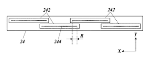
図2は、ヘッドユニット24の構成を示す模式図である。ここでは、ヘッドユニット24のうち搬送ドラム21の搬送面と対向する面が示されている。
各ヘッドユニット24は、複数の記録素子243(図3)のノズル244が記録媒体Pの搬送方向と交差する方向(本実施形態では搬送方向と直交する方向、即ちX方向)に配列された4つの記録ヘッド242を備える。
ヘッドユニット24に含まれる4つの記録ヘッド242は、X方向についての配置範囲が互いに一部重複するように千鳥格子状に配置され、X方向に沿って1番目と3番目、及び2番目と4番目の記録ヘッド242のノズル244が同一線上に位置している。隣り合う記録ヘッド242がX方向に重複している部分のうち、図2に示される範囲Rにおいて、各記録ヘッド242に含まれるノズル244のX方向についての配置範囲が重複している。範囲Rにおいては、例えば範囲Rにノズル244を有する2つの記録ヘッド242のうち一方の記録ヘッド242のノズル244のみからインクが吐出されるように設定される。
ヘッドユニット24は、当該ヘッドユニット24に含まれるノズル244のX方向についての配置範囲が、搬送ドラム21により搬送される記録媒体Pのうち画像が形成可能な領域のX方向の幅をカバーするラインヘッドであり、ヘッドユニット24は、画像の記録時には搬送ドラム21に対して位置が固定されて用いられる。即ち、インクジェット記録装置1は、シングルパス形式のインクジェット記録装置である。また、ヘッドユニット24におけるノズル244は、例えば、X方向に1200dpi(dot per inch)で配列されている。
なお、記録ヘッド242は、ノズル244の列を2以上備えていても良い。例えば、X方向に配列されたノズル244の列を2列備え、これら2列のノズル244がX方向についてノズル244の配置間隔の2分の1だけ互いにずれた状態で配置された構成であっても良い。また、ヘッドユニット24が有する記録ヘッド242の数は、3つ以下又は5つ以上であっても良い。FIG. 2 is a schematic view showing the configuration of the
Each
The four recording heads 242 included in the
The
The
また、ヘッドユニット24は、記録ヘッド242を駆動する記録ヘッド駆動部241(図3)を備える。記録ヘッド駆動部241は、各記録ヘッド242に対して画像データに応じた駆動波形の電圧信号を供給する駆動回路と、この駆動回路に適切なタイミングで画像データを供給する駆動制御回路とを有する。
記録ヘッド242に含まれる記録素子243の各々は、インクを貯留する圧力室と、圧力室の壁面に設けられた圧電素子と、ノズル244とを備える。記録ヘッド駆動部241の駆動回路から圧電素子に当該圧電素子を変形動作させる駆動波形の電圧信号が印加されると、この電圧信号に応じて圧力室内の圧力が変化し、圧力室に連通するノズル244からインクを吐出するインク吐出動作(記録動作)が行われる。
また、ヘッドユニット24では、ノズル244の形成時の加工ばらつき、圧電素子の特性ばらつき、ノズル244の詰まり、又はノズル開口部の汚れなどによる閉塞などに起因してインク吐出不良(記録動作不良)の記録素子243(不良記録素子)が生じる場合がある。Further, the
Each of the
Further, in the
記録ヘッド242から吐出されるインクとしては、温度によってゲル状又はゾル状に相変化し、また紫外線等のエネルギー線を照射することにより硬化する性質を有するものが用いられる。
各ヘッドユニット24は、図示しないインク加熱部を備える。当該インク加熱部は、制御部40による制御下で動作し、ヘッドユニット24内に貯留されるインクをゾル状となる温度に加熱する。記録ヘッド242は、加熱されてゾル状となったインクを吐出する。As the ink ejected from the
Each
定着部25は、搬送ドラム21のX方向の幅に亘って配置された発光部を有し、搬送ドラム21に載置された記録媒体Pに対して当該発光部から紫外線等のエネルギー線を照射して記録媒体P上に吐出されたインクを硬化させて定着させる。定着部25の発光部は、搬送方向についてヘッドユニット24の搬送方向下流側に搬送ドラム21と対向して配置される。
The fixing
画像読取部26は、定着部25によるインクの定着位置よりも搬送方向下流側の位置において、搬送ドラム21に対向して配置され、搬送ドラム21により搬送される記録媒体Pに形成されている画像を所定の読取範囲で読み取って当該画像の撮像データを出力する。
本実施形態では、画像読取部26は、搬送ドラム21により搬送される記録媒体Pに対して光を照射する光源と、記録媒体Pに入射した光の反射光の強度を検出する撮像素子がX方向に配列されたラインセンサーとを備える。このラインセンサーは、画像を複数の波長成分ごと、例えば、R(レッド)、G(グリーン)、B(ブルー)の3波長でそれぞれ取得可能となっている。ラインセンサーの各撮像素子による読み取り解像度は、例えば、幅方向に600dpiである。即ち、このイメージセンサーは、ノズル244の配列間隔に対応する解像度よりも低い解像度で画像を取得するものであっても良い。
なお、画像読取部26の構成はこれに限られず、例えばラインセンサーに代えてエリアセンサーが用いられても良い。The
In the present embodiment, the
The configuration of the
デリバリー部27は、内側が2本のローラーにより支持された輪状のベルトを有するベルトループ272と、記録媒体Pを搬送ドラム21からベルトループ272に受け渡す円筒状の受け渡しドラム271とを有し、受け渡しドラム271により搬送ドラム21からベルトループ272上に受け渡された記録媒体Pをベルトループ272により搬送して後処理部30に送出する。 The delivery unit 27 has a belt loop 272 having a ring-shaped belt whose inside is supported by two rollers, and a cylindrical transfer drum 271 that transfers the recording medium P from the transfer drum 21 to the belt loop 272. The recording medium P delivered from the transfer drum 21 onto the belt loop 272 by the transfer drum 271 is conveyed by the belt loop 272 and sent to the post-processing unit 30.
反転部28は、記録媒体Pの表裏を反転させる場合にCPU41による制御下で動作し、受け渡しドラム271から引き渡された記録媒体Pの表裏を反転させて搬送ドラム21に引き渡し、搬送面上に載置させる。反転部28は、第1ドラム281、第2ドラム282、及びベルトループ283を備える。
反転部28では、記録媒体Pは、図1における時計方向に回転する受け渡しドラム271から図1における反時計方向に回転する第1ドラム281に受け渡され、続いて図1における時計方向に回転する第2ドラム282、反時計方向に回転するベルトループ283に順に引き渡される。記録媒体Pの後端が第2ドラム282とベルトループ283とのニップ部近傍に到達するとベルトループ283の回転方向が図1における時計方向に変更され、記録媒体Pは、受け渡しドラム222の搬送方向上流側で搬送ドラム21の搬送面上に載置される。反転部28により搬送面上に載置された記録媒体Pは、画像が形成された面が搬送面に当接する状態で搬送ドラム21に再び保持される。
なお、反転部28の構成は上記に限られず、記録媒体Pの表裏を反転させて搬送ドラム21に引き渡すことが可能な種々の構成から適宜選択することができる。The reversing unit 28 operates under the control of the
In the reversing section 28, the recording medium P is delivered from the transfer drum 271 rotating clockwise in FIG. 1 to the first drum 281 rotating counterclockwise in FIG. 1, and then rotating clockwise in FIG. It is delivered in order to the second drum 282 and the belt loop 283 that rotates counterclockwise. When the rear end of the recording medium P reaches the vicinity of the nip portion between the second drum 282 and the belt loop 283, the rotation direction of the belt loop 283 is changed to the clockwise direction in FIG. 1, and the recording medium P moves in the transport direction of the transfer drum 222. It is placed on the transport surface of the transport drum 21 on the upstream side. The recording medium P placed on the transport surface by the reversing portion 28 is held again by the transport drum 21 in a state where the surface on which the image is formed is in contact with the transport surface.
The configuration of the reversing unit 28 is not limited to the above, and can be appropriately selected from various configurations in which the front and back surfaces of the recording medium P can be inverted and delivered to the transport drum 21.
後処理部30は、デリバリー部27により画像記録部20から送り出された記録媒体Pを裁断する裁断部31と、裁断部31により裁断された記録媒体Pが載置される板状の排紙トレー32とを有する。このうち裁断部31は、記録媒体Pを搬送するベルトループ311,312と、ベルトループ311により搬送されている記録媒体PをX方向の所定の位置でY方向に沿って裁断するカッター313と、ベルトループ311及びベルトループ312の間において記録媒体Pを当該記録媒体P上の所定の位置でX方向に沿って裁断するカッター314とを備える。裁断部31は、記録媒体Pに形成された複数の通常画像各々の良否判定結果を制御部40から受け取って、当該良否判定結果に応じた態様で記録媒体Pを裁断し、排紙トレー32に搬送する。例えば、裁断部31は、記録媒体Pを裁断した後、不良と判定された通常画像が形成されている記録媒体と、適正に通常画像が形成された記録媒体とを異なる排紙トレー32に排出する。また、適正に形成された通常画像がない場合には、記録媒体Pを裁断せずに排紙トレー32に搬送する。
なお、後処理部30には、必要に応じて裁断された記録媒体Pを製本する製本部が設けられていても良い。The post-processing unit 30 has a cutting
The post-processing unit 30 may be provided with a bookbinding unit for binding the cut recording medium P, if necessary.
図3は、インクジェット記録装置1の主要な機能構成を示すブロック図である。
インクジェット記録装置1は、CPU41(Central Processing Unit)(画像形成制御手段、不良検出手段、判定手段、不良記録素子同定手段、補正手段、回復制御手段)、RAM42(Random Access Memory)、ROM43(Read Only Memory)及び記憶部44(記憶手段)を有する制御部40と、加熱部23と、ヘッドユニット24の記録ヘッド242を駆動する記録ヘッド駆動部241と、定着部25と、画像読取部26と、裁断部31と、搬送駆動部51と、メンテナンス部52(回復手段)と、操作表示部53と、入出力インターフェース54と、バス55などを備える。FIG. 3 is a block diagram showing a main functional configuration of the inkjet recording device 1.
The inkjet recording device 1 includes a CPU 41 (Central Processing Unit) (image formation control means, defect detection means, determination means, defect recording element identification means, correction means, recovery control means), RAM 42 (Random Access Memory), ROM 43 (Read Only). A
CPU41は、ROM43に記憶された各種制御用のプログラムや設定データを読み出してRAM42に記憶させ、当該プログラムを実行して各種演算処理を行う。CPU41は、これによりインクジェット記録装置1の全体動作を統括制御する。
The
RAM42は、CPU41に作業用のメモリー空間を提供し、一時データを記憶する。RAM42には、メンテナンス動作の実施状況の判別に用いられるメンテナンス済みフラグが記憶される。ここで、メンテナンス済みフラグは、1ビットで示される2値データである。なお、RAM42は、不揮発性メモリーを含んでいても良い。
The
ROM43は、CPU41により実行される各種制御用のプログラムや設定データ等を格納する。この設定データには、記録素子243のノズル244からのインク吐出不良の検査に用いられるテストチャート(テスト画像)や欠位置特定チャート(同定用画像)の画像データであるテスト画像データが含まれる。なお、ROM43に代えてEEPROM(Electrically Erasable Programmable Read Only Memory)やフラッシュメモリー等の書き換え可能な不揮発性メモリーが用いられても良い。
The
記憶部44は、入出力インターフェース54を介して外部装置2から入力されたプリントジョブ及び当該プリントジョブに係る画像データが記憶される。この画像データは、ベクター画像データをラスタライズ処理すること等により得られるラスター画像データである。ラスタライズ処理は、外部装置2により行われても良いし、インクジェット記録装置1の制御部40又は制御部40とは別個に設けられた図示略の画像処理部により行われても良い。
本実施形態のプリントジョブに係る画像データにより示される画像には、記録媒体P上の一の記録範囲において他の通常画像と重ならない状態で形成されるように割り付けがなされた複数の通常画像が含まれている。ここで、通常画像とは、記録媒体Pに対する形成対象の画像であってテストチャートや欠位置特定チャートといったインク吐出不良の検査に用いられる画像を除く画像である。複数の通常画像は、各通常画像の周囲での裁断を容易にするために互いに分離されて配置されることが好ましい。このように割り付けがなされる通常画像の例としては、複数ページで構成される文書における各ページに係る画像や、製品パッケージの展開図が複数配置された画像における各展開図が挙げられる。
また、プリントジョブには、画像データのうち複数の通常画像各々に係る良否判定対象領域の範囲を示す配置データ(配置情報、良否判定対象領域情報)や、記録媒体Pの裁断位置を示す裁断位置データが含まれる。ここで、良否判定対象領域は、各通常画像において適正な画像形成を要する領域として設定された領域であり、後述する通常画像の良否判定の対象となる領域である。また、適正な画像形成とは、不良記録素子のインク吐出不良に起因した画質劣化が生じない状態での画像形成をいう。この良否判定対象領域は、通常は通常画像の輪郭により定められる領域であるが、通常画像の用途に応じて通常画像のうち一部の領域とされても良い。上記配置データは、例えば良否判定対象領域が画像データにおける画素の配列方向と平行な辺を有する矩形の画素群に対応する場合には、当該矩形の対頂点の画素の座標により良否判定対象領域を示すものとすることができる。あるいは、配置データは、良否判定対象領域の輪郭線を特定するデータであっても良く、また、画像データと同一の画素配列を有する配置特定用の画像データを設けて当該配置特定用の画像データにおいて良否判定対象領域と対応する画素とそれ以外の画素とを異なる画素値とすることで良否判定対象領域を特定するものであっても良い。
また、記憶部44には、ヘッドユニット24の複数の記録素子243のうち検査によりインク吐出不良と同定された不良記録素子(不良ノズル)の位置データ及びその補完設定が記憶される。
記憶部44としては、例えばHDD(Hard Disk Drive)が用いられ、また、DRAM(Dynamic Random Access Memory)などが併用されても良い。The
The image indicated by the image data related to the print job of the present embodiment includes a plurality of normal images allocated so as to be formed in a recording range on the recording medium P so as not to overlap with other normal images. include. Here, the normal image is an image to be formed on the recording medium P, excluding an image used for inspecting ink ejection defects such as a test chart and a missing position identification chart. The plurality of normal images are preferably arranged separately from each other to facilitate cutting around each normal image. Examples of the normal image to be allocated in this way include an image related to each page in a document composed of a plurality of pages and each development drawing in an image in which a plurality of development drawings of a product package are arranged.
Further, in the print job, the arrangement data (arrangement information, quality determination target area information) indicating the range of the quality determination target area related to each of the plurality of normal images among the image data, and the cutting position indicating the cutting position of the recording medium P are used. Contains data. Here, the quality determination target area is an area set as an area that requires proper image formation in each normal image, and is a region that is a target of quality judgment of a normal image described later. Further, proper image formation refers to image formation in a state where image quality deterioration due to poor ink ejection of a defective recording element does not occur. This pass / fail judgment target area is usually an area defined by the contour of the normal image, but may be a part of the normal image depending on the use of the normal image. For example, when the quality determination target area corresponds to a rectangular pixel group having sides parallel to the pixel arrangement direction in the image data, the quality determination target area is determined by the coordinates of the pixels of the opposite vertices of the rectangle. Can be shown. Alternatively, the arrangement data may be data for specifying the contour line of the pass / fail judgment target area, or image data for arrangement identification having the same pixel arrangement as the image data is provided and the image data for specifying the arrangement is provided. In the above, the quality determination target area may be specified by setting different pixel values for the pixels corresponding to the quality determination target area and the other pixels.
Further, the
As the
記録ヘッド駆動部241は、CPU41から供給される制御信号及び画像データに基づいて記録ヘッド242にインクの吐出を行わせる。詳しくは、CPU41から制御信号及び画像データが供給されると、記録ヘッド駆動部241の駆動制御回路は、駆動回路により記録ヘッド242の記録素子243の圧電素子に駆動波形の電圧信号を出力させて、記録素子243のノズル244から画像データに応じた量のインクが吐出される吐出動作、又は画像データがインクの非吐出に対応する場合や画像記録動作の終了後次の画像記録動作の開始前において実行されるインクが吐出されない非吐出動作を記録ヘッド242に行わせる。
The recording
搬送駆動部51は、CPU41から供給される制御信号に基づいて搬送ドラム21の搬送ドラムモーターに駆動信号を供給して搬送ドラム21を所定の速度及びタイミングで回転させる。また、搬送駆動部51は、CPU41から供給される制御信号に基づいて媒体供給部12、受け渡しユニット22、デリバリー部27を動作させるためのモーターに駆動信号を供給して、記録媒体Pの搬送ドラム21への給紙及び搬送ドラム21からの排出を行わせる。また、搬送駆動部51は、CPU41から供給される制御信号に基づいて反転部28の第1ドラム281、第2ドラム282、及びベルトループ283を動作させ、反転部28により記録媒体Pの表裏を反転させる。また、搬送駆動部51は、CPU41から供給される制御信号に基づいて裁断部31のベルトループ311,312を動作させ、カッター313,314の動作タイミングに合わせて記録媒体Pを搬送させる。
The
メンテナンス部52は、ヘッドユニット24の不良記録素子のうち正常にインクが吐出される正常状態に回復可能な記録素子243を当該正常状態に回復させ得るメンテナンス動作(回復動作)を行う。このメンテナンス動作には、ヘッドユニット24のノズル244からインクを強制的に吐出させてノズルの目詰まりを解消させる加圧パージと、ヘッドユニット24のノズル244が形成されたノズル面を拭って清掃するワイピングとが含まれる。
メンテナンス部52は、加圧パージが行われる場合に記録素子243の圧力室と連通するインクの供給経路のうち所定の加圧位置でインクを加圧する図示略の加圧ポンプを有する。また、メンテナンス部52は、ノズル面を拭う図示略の清掃ローラーを有する。清掃ローラーは、例えば所定の薬液を含ませたワイピングクロスが外周面に巻かれた円筒状の部材とすることができる。The maintenance unit 52 performs a maintenance operation (recovery operation) that can restore the
The maintenance unit 52 has a pressure pump (not shown) that pressurizes ink at a predetermined pressure position in the ink supply path communicating with the pressure chamber of the
操作表示部53は、液晶ディスプレイや有機ELディスプレイといった表示装置と、操作キーや、表示装置の画面に重ねられて配置されたタッチパネルといった入力装置とを備える。操作表示部53は、表示装置において各種情報を表示させ、また入力装置に対するユーザーの入力操作を操作信号に変換して制御部40に出力する。
The
入出力インターフェース54は、外部装置2との間でデータの送受信を行う手段であり、例えば各種シリアルインターフェース、各種パラレルインターフェースのいずれか又はこれらの組み合わせで構成される。
The input /
バス55は、制御部40と他の構成との間で信号の送受信を行うための経路である。
The
外部装置2は、例えばパーソナルコンピューターであり、入出力インターフェース54を介してプリントジョブ及び画像データ等を制御部40に供給する。
The
次に、本実施形態のインクジェット記録装置1における記録素子243のインク吐出不良検査、及び当該検査の結果に基づく複数の通常画像の良否判定について説明する。
本実施形態のインクジェット記録装置1では、記録媒体P上の一の記録範囲に対して割り付けがなされた複数の通常画像を含む画像形成が行われるごとにインク吐出不良検査が実施される。このインク吐出不良検査では、記録媒体Pに形成されたテストチャートの画像読取部26による読み取り結果に基づいてインク吐出不良の有無が検出される。Next, an ink ejection defect inspection of the
In the inkjet recording apparatus 1 of the present embodiment, an ink ejection defect inspection is performed every time an image is formed including a plurality of normal images allocated to one recording range on the recording medium P. In this ink ejection defect inspection, the presence or absence of ink ejection defects is detected based on the reading result of the
図4は、記録媒体Pに形成される通常画像Im1〜Im4及びテストチャート60の例を示す図である。図4では、ヘッドユニット24により画像が形成され搬送ドラム21に保持されている記録媒体Pが示されている。以下では、通常画像Im1〜Im4のうち何れかを指す場合には通常画像Imと記す。
図4では、プリントジョブに係る画像データに基づいて形成された画像は、X方向及びY方向について2行2列に割り付けられて配列された4つの同一の通常画像Im1〜Im4を含んでいる。このように4つの通常画像Im1〜Im4を形成した後、裁断部31において各通常画像Im1〜Im4の周囲を裁断することで、通常画像Im1〜Im4が各々形成された記録媒体が取得される。
また、通常画像Im1〜Im4の−Y方向側(搬送方向上流側)の余白には、搬送方向と直交する幅方向(X方向)に延びる長矩形のテストチャート60が通常画像Im1〜Im4の各々と個別に対応するように形成されている。また、図4の記録媒体Pに記録された、複数の通常画像Im及びテストチャート60を含む画像を複合画像とも記す。FIG. 4 is a diagram showing an example of normal images Im1 to Im4 and a
In FIG. 4, the image formed based on the image data related to the print job includes four identical normal images Im1 to Im4 arranged in two rows and two columns in the X and Y directions. After forming the four normal images Im1 to Im4 in this way, the cutting
Further, in the margin on the −Y direction side (upstream side in the transport direction) of the normal images Im1 to Im4, a long
図5A及び図5Bは、テストチャート60を拡大して示す図である。図5Aは、記録素子243のインク吐出不良がない場合のテストチャート60を示し、図5Bは、記録素子243のインク吐出不良がある場合のテストチャート60の例を示す。
5A and 5B are enlarged views of the
図5Aに示されるように、テストチャート60は、YMCKの各色のインクで各々形成された色別テストチャート61〜64からなる。色別テストチャート61〜64は、濃淡の判別がしやすい画像、例えば、各色で濃度が一定のハーフトーン画像である。
テストチャート60は、X方向の形成範囲が、対応する通常画像Imに係る良否判定対象領域のX方向の形成範囲と等しくなるように形成されている。即ち、テストチャート60と当該テストチャート60に対応する通常画像Imの良否判定対象領域とがヘッドユニット24における同一範囲の記録素子243により形成されている。図4の通常画像Imでは、良否判定対象領域は、通常画像Imの輪郭により囲まれた領域とされており、テストチャート60のX方向の形成範囲は、対応する通常画像ImのX方向の形成範囲と等しくなっている。
テストチャート60は、記録媒体P上に設定された通常画像Im1〜Im4の形成範囲外に適宜形成可能であるが、通常画像Im1〜Im4の各々に対してY方向に所定の間隔を空けて形成することで、画像読取部26による読取タイミングを容易に制御可能とするとともに、記録媒体Pの搬送速度に応じた適切な時間間隔でこのテストチャート60の読み取りや解析に係る動作が無理なく行われる。
テストチャート60は、画像読取部26により読み取られる。画像読取部26によるこのテストチャート60の撮像データは、制御部40のRAM42に一時記憶されて、当該制御部40のCPU41による不良記録素子の検出に用いられる。As shown in FIG. 5A, the
The
The
The
制御部40では、撮像データ中のテストチャート60における濃淡(色むら)の有無の検出が行われる。ヘッドユニット24に不良記録素子があって当該不良記録素子のノズル244からのインク着弾位置における濃度が低下すると、図5Bに示されるように、形成されたテストチャート60に色むらEが生じる。この色むらEは、テストチャート60の撮像データから制御部40により検出される。ここで、上述のように、画像読取部26のラインセンサーの読み取り解像度は、ノズル配列よりも粗い。従って、テストチャート60からは、色むらEを生じさせる要因となっている不良記録素子は、複数の記録素子243を単位としたブロックで特定され得る。或いは、この段階では、不良記録素子の有無のみが判別されるだけであっても良い。
The
インクジェット記録装置1では、色むらEが検出されたテストチャート60と対応する通常画像Imを不良と判定することにより通常画像Im1〜Im4の良否が判定される。
例えば、図4に示されるように4つのテストチャート60のうち通常画像Im3に対応するテストチャート60に色むらEが検出された場合には、通常画像Im3の少なくとも一部に不良記録素子のインク吐出不良に起因した画質不良個所eが生じている。このため、色むらEが検出されたテストチャート60と対応する通常画像Im3が不良と判定され、残りの通常画像Im1,Im2,Im4が適正に形成された通常画像と判定される。画質不良個所eは、インク吐出不良により不良記録素子からインクが吐出されない場合には白スジとして視認されるが、図4では、便宜上、ハッチングにより画質不良個所eが示されている(図8〜図11も同様)。
ここで、通常画像Im1に対応するテストチャート60に色むらEが検出されていないことから、通常画像Im3に対応するテストチャート60に色むらEを生じさせる要因となっているインク吐出不良は、通常画像Im1に対応するテストチャート60の形成終了後、通常画像Im3に対応するテストチャート60の形成開始までの間に生じたことが分かる。このため、通常画像Im1は、通常画像Im3に対応するテストチャート60に色むらが検出されていても、通常画像Im1に対応するテストチャート60に色むらEがないことから適正に形成されたものと判定される。このように、通常画像Im1〜Im4に各々対応してY方向について異なる位置にテストチャート60を形成することにより、Y方向に隣接して配列された複数の通常画像Im各々の良否をそれぞれ独立して判定することができる。In the inkjet recording device 1, the quality of the normal images Im1 to Im4 is determined by determining the normal image Im corresponding to the
For example, when color unevenness E is detected in the
Here, since the color unevenness E is not detected on the
少なくとも1つの通常画像Imが適正に形成されていると判別された場合には、記録媒体Pが裁断部31により裁断され、適正に通常画像Imが形成された記録媒体が取得される。
When it is determined that at least one normal image Im is properly formed, the recording medium P is cut by the cutting
上記のインク吐出不良検査においてテストチャート60に色むらEが検出された場合にそのまま次の記録媒体Pに対して画像の形成を行うと、不良記録素子のインク吐出不良が回復しない限り再度当該不良記録素子に起因した画質不良個所eが生じる。このため、インクジェット記録装置1では、テストチャート60に色むらEが検出された場合には、以下の色むら対処動作が行われる。
When color unevenness E is detected on the
色むら対処動作では、まず記録媒体Pを一枚用いて各記録素子243を単位としてインク吐出不良の検出を行うための欠位置特定チャートが出力される。そして、この欠位置特定チャートの画像が画像読取部26により読み取られて制御部40により解析されることでインクの欠位置が特定されて、不良記録素子が同定される。
ここで、欠位置特定チャートは、例えばヘッドユニット24が有する複数の記録素子243のノズル244の各々から吐出されたインクにより記録された複数のラインからなるラインパターンとすることができる。このラインパターンを読み取って得られた撮像データにおいて、欠損したラインや記録素子243のノズル244と対応する適正な位置に記録されていないラインがある場合には、当該ラインに対応する記録素子243が不良記録素子として特定される。In the color unevenness coping operation, first, a missing position identification chart for detecting an ink ejection defect is output in units of each
Here, the missing position identification chart can be, for example, a line pattern composed of a plurality of lines recorded by ink ejected from each of the
不良記録素子が同定されると、不良記録素子からのインクを非吐出とするとともに、不良記録素子により吐出されるはずのインクを、この不良記録素子の周辺の記録素子243からの吐出インク量を増加させることにより補完する補完処理の設定が行われる。この補完処理では、不良記録素子からのインク吐出が行われないように、かつ周辺の記録素子243からのインク吐出量が不良記録素子から非吐出となるインク量に応じて増加するように複数の通常画像Imに係る画像データ及びテストチャート60に係るテスト画像データが補正される。
補完処理の設定がなされると、新たな記録媒体P上に、上記の通常画像Imの良否判定において不良と判定された画像を適正に形成する再形成動作が行われる。ここで、通常画像Imの良否判定において同一の通常画像Imが複数不良と判定されている場合には、不良と判定された数だけ当該通常画像Imが新たな記録媒体P上に形成される。When the defective recording element is identified, the ink discharged from the defective recording element is not ejected, and the ink ejected from the defective recording element is discharged from the
When the complement processing is set, a reshaping operation is performed on the new recording medium P to appropriately form an image determined to be defective in the above-mentioned quality determination of the normal image Im. Here, when the same normal image Im is determined to be a plurality of defects in the quality determination of the normal image Im, the normal image Im is formed on the new recording medium P by the number determined to be defective.
検出された記録動作不良が形成画像の画質の劣化に係る所定の条件を満たす場合、例えば記録動作不良の記録素子として同定された不良記録素子の数が多かったり、不良記録素子が複数連続していたりすることにより適正な補完を行うことができない場合には、メンテナンス部52によるメンテナンス動作が行われて不良記録素子の正常状態への回復が図られる。
メンテナンス動作のうち加圧パージは、記録素子243の圧力室と連通するインクの供給経路のうち所定の加圧位置でメンテナンス部52の加圧ポンプによりインクが加圧されることにより行われる。このインクの加圧により、記録素子243のノズル244から強制的にインクが吐出されてノズル244の目詰まりが解消される。加圧パージは、ヘッドユニット24のノズル面の下部に所定のインク受容部が位置した状態で行われる。
また、メンテナンス動作のうちワイピングは、ヘッドユニット24のノズル面にメンテナンス部52の清掃ローラーが当接した状態で清掃ローラーを回転させながらノズル面の延在方向に移動させることにより行われる。このワイピングにより、ノズル面全体が清掃ローラーの外周面に貼り付けられたワイピングクロスにより拭われてノズル面及びノズル244の開口部に付着したインクや異物が除去される。When the detected recording malfunction satisfies a predetermined condition related to the deterioration of the image quality of the formed image, for example, the number of defective recording elements identified as the recording element of the recording malfunction is large, or a plurality of defective recording elements are continuous. If proper complementation cannot be performed due to such a problem, the maintenance unit 52 performs a maintenance operation to restore the defective recording element to the normal state.
In the maintenance operation, the pressure purge is performed by pressurizing the ink by the pressure pump of the maintenance unit 52 at a predetermined pressure position in the ink supply path communicating with the pressure chamber of the
Further, in the maintenance operation, wiping is performed by moving the cleaning roller in the extending direction of the nozzle surface while rotating the cleaning roller in a state where the cleaning roller of the maintenance unit 52 is in contact with the nozzle surface of the
メンテナンス処理が終了すると、再び欠位置特定チャートによる不良記録素子の同定、及び当該同定の結果に基づく補完処理の設定が行われる。この結果、適正な補完を行うことができる場合には、引き続き上述の再形成動作が行われる。一方、ここでも適正な補完を行うことができないと判別されると、操作表示部53により、例えばヘッドユニット24の交換を促すエラー表示が行われる。
When the maintenance process is completed, the defective recording element is identified again by the missing position identification chart, and the complementary process is set based on the result of the identification. As a result, if proper complementation can be performed, the above-mentioned reshaping operation is continuously performed. On the other hand, if it is determined that proper complement cannot be performed here as well, the
続いて、上述のインク吐出不良検査及び色むら対処動作に係る処理を含む画像形成処理のCPU41による制御手順について説明する。
Subsequently, the control procedure by the
図6は、画像形成処理の制御手順を示すフローチャートである。
この画像形成処理は、例えば入出力インターフェース54を介して外部装置2からプリントジョブ及び画像データが制御部40に入力された場合に実行される。FIG. 6 is a flowchart showing a control procedure of the image forming process.
This image forming process is executed when, for example, a print job and image data are input to the
画像形成処理が開始されると、CPU41は、画像データに基づいてヘッドユニット24により画像を形成させる(ステップS101)(画像形成ステップ)。即ち、CPU41は、搬送駆動部51に制御信号を出力して当該搬送駆動部51により搬送ドラム21を回転させて記録媒体Pを搬送させる。そして、CPU41は、画像データ及び制御信号を記録ヘッド駆動部241に供給して、搬送ドラム21の回転に応じた適切なタイミングで記録ヘッド駆動部241により駆動波形の電圧信号を記録ヘッド242に出力させることで、搬送ドラム21により搬送される記録媒体P上にヘッドユニット24の記録素子243からインクを吐出させて記録媒体Pに複数の通常画像Imを含む画像、及び各通常画像Imに対応したテストチャート60を形成させる。ここで、CPU41は、搬送ドラム21の回転に応じて通常画像Imが形成されるタイミングでは複数の通常画像Imに係る画像データを記録ヘッド駆動部241に供給するとともに、テストチャート60が形成されるタイミングではテスト画像に係るテスト画像データを記録ヘッド駆動部241に供給することで、記録媒体Pに複数の通常画像Imとテストチャート60とを形成させる。また、CPU41は、プリントジョブの配置データに示された各通常画像ImのX方向の形成範囲を参照し、当該形成範囲と等しいX方向の範囲に各テストチャート60を形成させる。
When the image forming process is started, the
CPU41は、搬送ドラム21により記録媒体Pを搬送させながら画像読取部26により適切な間隔で繰り返し記録媒体Pに形成された通常画像Im及びテストチャート60を読み取らせ、撮像データを取得して記憶部44に記憶させる(ステップS102)。
The
CPU41は、テストチャート60の撮像データから色むらEの検出を行う(ステップS103)(不良検出ステップ)。CPU41は、何れかのテストチャート60において色むらEが検出されたか否かを判別する(ステップS104)(判定ステップ)。
The
全てのテストチャート60において色むらEが検出されていないと判別された場合には(ステップS104で“No”)、CPU41は、搬送駆動部51に制御信号を出力して裁断部31のベルトループ311,312により記録媒体Pを搬送させるとともに裁断部31のカッター313,314を適切なタイミングで動作させて、記録媒体Pをプリントジョブにより示された所定の位置で裁断させ(ステップS110)、排紙トレー32に排出させる(ステップS111)。これにより、適正に形成された一の通常画像Imが各々形成された複数の記録媒体が得られる。ステップS111の処理が終了すると、CPU41は、画像形成動作を終了させる。
When it is determined that the color unevenness E is not detected in all the test charts 60 (“No” in step S104), the
何れかのテストチャート60において色むらEが検出されたと判別された場合には(ステップS104で“Yes”)、CPU41は、適正に形成された通常画像Imがあるか否かを判別する(ステップS105)(判定ステップ)。ここでは、CPU41は、色むらEが検出されていないテストチャート60がある場合に、適正に形成された通常画像Imがあると判別する。また、CPU41は、色むらEが検出されていないテストチャート60と対応する通常画像Imを適正に形成されているものと判定する。
When it is determined that the color unevenness E is detected in any of the test charts 60 (“Yes” in step S104), the
適正に形成された通常画像があると判別された場合には(ステップS105で“Yes”)、CPU41は、搬送駆動部51及び裁断部31に制御信号を出力して裁断部31において記録媒体Pをプリントジョブにより示された所定の位置で裁断させ(ステップS106)、排紙トレー32に排出させる(ステップS107)。なお、ステップS107では、複数の排紙トレー32を設けて、適正に通常画像Imが形成された記録媒体と、不良と判定された通常画像Imが形成された記録媒体とを異なる排紙トレー32に振り分けて排出させても良い。
ステップS105において適正に形成された通常画像Imがないと判別された場合には(ステップS105で“No”)、CPU41は、記録媒体Pを裁断させずに排紙トレー32に排出させる(ステップS107)。When it is determined that there is an appropriately formed normal image (“Yes” in step S105), the
If it is determined in step S105 that there is no properly formed normal image Im (“No” in step S105), the
CPU41は、ステップS105における判別の結果に基づいて、次回の画像形成処理に係る設定を行う(ステップS108)。即ち、CPU41は、形成された複数の通常画像Imのうち不良と判別された通常画像Imが次回の画像形成処理において形成されるようにプリントジョブを生成して記憶部44に記憶させる。なお、不良と判別された通常画像Imが次々回以降の画像形成処理において形成されるように設定を行っても良い。
The
ステップS108の処理が終了すると、CPU41は、色むら対処処理を実行する(ステップS109)。
When the process of step S108 is completed, the
図7は、色むら対処処理の制御手順を示すフローチャートである。
色むら対処処理が開始されると、CPU41は、不良記録素子を特定するための欠位置特定チャートをヘッドユニット24により記録媒体P上に形成させる(ステップS201)。即ち、CPU41は、搬送ドラム21の回転に応じて欠位置特定チャートに係るテスト画像データを記録ヘッド駆動部241に供給することで、記録媒体Pに欠位置特定チャートを形成させる。FIG. 7 is a flowchart showing a control procedure of the color unevenness coping process.
When the color unevenness coping process is started, the
CPU41は、搬送ドラム21により記録媒体Pを搬送させながら画像読取部26により適切な間隔で繰り返し記録媒体Pに形成された欠位置特定チャートを読み取らせ、撮像データを取得して記憶部44に記憶させる(ステップS202)。
The
CPU41は、欠位置特定チャートから欠位置を特定して不良記録素子を同定する(ステップS203)。
The
CPU41は、同定された吐出不良記録素子によるインク吐出量の不足を周辺の記録素子243で補完することが可能であるか否かを判別する(ステップS204)。可能であると判別された場合には(ステップS204で“Yes”)、CPU41は、周辺の記録素子243のインク吐出量を調整する補完設定を行う(ステップS205)。即ち、CPU41は、不良記録素子からのインク吐出が行われないように、また周辺の記録素子243からのインク吐出量が不良記録素子から非吐出となるインク量に応じて増加するように、次回の画像形成処理で形成される通常画像の画像データ及びテストチャート60に係るテスト画像データを補正する。ステップS205の処理が終了すると、CPU41は、色むら対処処理を終了させる。色むら対処処理の終了後、次回の画像形成処理が開始された場合には、CPU41は、画像形成の際に補完設定に基づいて各記録素子243のインク吐出量を調整する。
The
周辺の記録素子243で不良記録素子が吐出すべきインクの補完を行うことが可能ではないと判別された場合には(ステップS204で“No”)、CPU41は、メンテナンス済みスフラグがオフに設定されているか否かを判別する(ステップS206)。
When it is determined by the
メンテナンス済みフラグがオフに設定されていると判別された場合には(ステップS206で“Yes”)、CPU41は、メンテナンス部52によりメンテナンス動作を行わせる(ステップS207)。メンテナンス動作が終了すると、CPU41は、メンテナンス済みフラグをオンに設定する(ステップS208)。ステップS208の処理が終了すると、CPU41は、処理をステップS201に移行させる。
When it is determined that the maintenance flag is set to off (“Yes” in step S206), the
ステップS206においてメンテナンスフラグがオンに設定されていると判別された場合には(ステップS206で“No”)、CPU41は、操作表示部53に所定のエラー表示を行わせる(ステップS209)。このようにステップS206においてメンテナンスフラグがオンに設定されていると判別された場合は、メンテナンス動作(ステップS207)の実行後においても不良記録素子が残存し不良記録素子の補完を行うことができない状態であるため、メンテナンス動作以外のヘッドユニット24の交換といった対処を促すエラー表示が行われる。なお、操作表示部53に表示を行わせる態様に代えて、エラーの発生を示すランプを点灯させたり、所定のアラーム音を発生させたり、予め設定されたアドレスに対してメールを送信することによりユーザーに対してエラーを報知する態様であっても良い。
ステップS209の処理が終了すると、CPU41は、色むら対処処理を終了させる。If it is determined in step S206 that the maintenance flag is set to ON (“No” in step S206), the
When the process of step S209 is completed, the
以上のように、本実施形態に係るインクジェット記録装置1は、複数の記録素子243のインク吐出動作に応じて記録媒体Pに対してインクを付与するヘッドユニット24と、記録媒体P上の一の記録範囲に対して割り付けがなされた複数の形成対象の通常画像Imとテストチャート60とを含む複合画像をヘッドユニット24により記録媒体P上に形成させる画像形成制御手段としてのCPU41と、記録媒体P上に形成された画像を読み取る画像読取部26とを備え、CPU41は、画像読取部26により読み取られたテストチャート60から記録素子243のインク吐出不良を検出し(不良検出手段)、インク吐出不良の検出結果及び複合画像における各画像の配置データに基づいて複数の通常画像Im各々の良否を判定する(判定手段)。このような構成によれば、記録媒体P上に形成された上記複合画像のうちテストチャート60の読取結果から当該複合画像における画像の配置に基づいて各通常画像Imの良否判定が行われるため、容易かつ適切に複数の通常画像Im各々の良否を判定することができる。
As described above, the inkjet recording apparatus 1 according to the present embodiment includes a
また、インクジェット記録装置1は、記録媒体Pとヘッドユニット24とを相対移動させる搬送ドラム21を備え、CPU41は、所定の一の移動方向に相対移動する記録媒体Pに対してヘッドユニット24によりインクを吐出させて複数のテストチャート60を含む複合画像を形成させ(画像形成制御手段)、複数のテストチャート60は、複数の通常画像Im各々における判定の対象となる良否判定対象領域の上記一の移動方向と直交する幅方向についての形成範囲と当該通常画像Imに対応するテストチャート60の当該幅方向についての形成範囲とが等しくなるように形成され、CPU41は、複数の通常画像Imの各々に対応するテストチャート60の画像読取部26による読取結果から不良検出手段としてのCPU41によりインク吐出不良が検出されたか否かに基づいて複数の通常画像Im各々の良否を判定する(判定手段)。これにより、複数の通常画像Imの各々に対応するテストチャート60においてインク吐出不良を示す色むらEが検出されたか否かに基づいて容易かつ適切に各通常画像Imの良否を判定することができる。
Further, the inkjet recording device 1 includes a transport drum 21 that moves the recording medium P and the
また、CPU41は、ヘッドユニット24により複数の通常画像Imの各々と個別に対応するテストチャート60をそれぞれ形成させる(画像形成制御手段)。これにより、通常画像Imごとに独立して良否を判定することができる。
Further, the
また、CPU41は、ヘッドユニット24により、通常画像Imよりも当該通常画像Imに各々対応するテストチャート60をヘッドユニット24に対する記録媒体Pの上記一の移動方向に沿った相対移動の方向についてインクが付与されるタイミングが相対的に遅い上流側に形成させる(画像形成制御手段)。これにより、通常画像Imの形成開始後にインク吐出不良が生じた場合であっても当該インク吐出不良を検出して通常画像Imを不良と判定することができるため、より適切に通常画像Imの良否を判定することができる。
Further, the
また、CPU41は、複数の通常画像Imが上記一の移動方向について異なる位置に形成される場合に、ヘッドユニット24により、一の通常画像Imに対応するテストチャート60を、当該一の通常画像Imに対して上流側に形成される他の通常画像Imよりも下流側に形成させる(画像形成制御手段)。このような構成によれば、記録媒体Pに対する画像の形成中にインク吐出不良が生じた場合に、当該インク吐出不良が生じる前に形成が完了したテストチャート60に対応する通常画像Imを適正なものと判定できるため、より適切に通常画像Imの良否を判定することができる。
Further, when a plurality of normal images Im are formed at different positions in the one moving direction, the
また、良否判定対象領域は、通常画像Imの輪郭により定められる。このような構成によれば、通常画像Imに含まれる全ての領域が適正に形成されているか否かに基づいて通常画像Imの良否を判定することができる。 Further, the pass / fail judgment target area is usually determined by the contour of the image Im. According to such a configuration, the quality of the normal image Im can be determined based on whether or not all the regions included in the normal image Im are properly formed.
また、CPU41は、記録媒体P上に形成され不良と判定された通常画像Imを他の記録媒体P上に適正に形成する再形成動作をヘッドユニット24により行わせる(画像形成制御手段)。このように、不良と判定された通常画像Imを選択的に他の記録媒体P上に形成させることにより、インクや記録媒体Pの無駄な消費を抑制しつつ適正に通常画像Imを形成させることができる。
Further, the
また、CPU41は、記録媒体P上に形成された複数の同一の通常画像Imが不良と判定された場合に、不良と判定された数の当該通常画像Imが他の記録媒体P上に形成されるようにヘッドユニット24により再形成動作を行わせる(画像形成制御手段)。このように、不良と判定された同一の通常画像Imを不良と判定された数だけ他の記録媒体P上に形成させることにより、インクや記録媒体Pの無駄な消費を抑制しつつ適正に通常画像Imを形成させることができる。
Further, in the
また、CPU41は、インク吐出不良が検出された場合に、ヘッドユニット24によりインク吐出不良に係る不良記録素子を同定するための欠位置特定チャートを当該記録媒体P上に形成させ(画像形成制御手段)、画像読取部26により読み取られた欠位置特定チャートから不良記録素子を同定し(不良記録素子同定手段)、不良記録素子が同定された場合に、不良記録素子及び当該不良記録素子の周辺の記録素子243による記録動作を調整することで当該不良記録素子の記録動作不良を補完した複合画像をヘッドユニット24により形成させる。このような構成によれば、通常画像Imに画質不良を生じさせる要因となっている不良記録素子を特定することができる。また、不良と判定された通常画像Imを適正な画質で形成させることができる。また、不良と判定された通常画像Imのみ他の記録媒体P上に形成させることにより、インク及び記録媒体Pの使用量を低減させることができる。
Further, when an ink ejection defect is detected, the
また、CPU41は、不良記録素子が同定された場合に、当該不良記録素子及び当該不良記録素子の周辺の記録素子によるインク吐出動作を調整し、当該不良記録素子のインク吐出動作不良が補完されるように複合画像に係る画像データを補正する(補正手段)。これにより、不良記録素子が生じても適正な画質で複合画像の形成を行うことができる。
Further, when the defective recording element is identified, the
また、インクジェット記録装置1は、インク吐出不良の記録素子243のうち正常なインク吐出動作を行う正常状態に回復可能な記録素子243を当該正常状態に回復させ得るメンテナンス動作を行うメンテナンス部52を備え、CPU41は、検出された記録素子243のインク吐出不良が形成画像の画質の劣化に係る所定の条件を満たす場合に、メンテナンス部52によるメンテナンス動作を開始させる(回復制御手段)。これにより、通常画像Imに画質不良を生じさせる要因となっている不良記録素子を正常状態に回復させて、次回以降の画像形成時に適正な通常画像Imが形成される可能性を高めることができる。
Further, the inkjet recording device 1 includes a maintenance unit 52 that performs a maintenance operation that can restore the
また、CPU41は、メンテナンス動作の開始前に一の記録媒体P上に形成され不良と判定された通常画像Imに係る再形成動作を、当該メンテナンス動作が行われた後にヘッドユニット24により行わせる(画像形成制御手段)。これにより、不良と判定された通常画像Imをより適正な画質で形成させることができる。また、不良と判定された通常画像Imのみ他の記録媒体P上に形成させることにより、インクや記録媒体Pの無駄な消費を抑制することができる。
Further, the
また、本実施形態の良否判定方法では、複数の記録素子243のインク吐出動作に応じて記録媒体Pに対してインクを付与するヘッドユニット24を備えるインクジェット記録装置1により形成された画像の良否の判定に際し、記録媒体P上の一の記録範囲に対して割り付けがなされた複数の形成対象の通常画像Imとテストチャート60とを含む複合画像をヘッドユニット24により当該記録媒体P上に形成させる画像形成ステップ、画像を読み取る画像読取部26により読み取られたテストチャート60から記録素子243の記録動作不良を検出する不良検出ステップ、不良検出ステップによる記録動作不良の検出結果及び複合画像における各画像の配置情報に基づいて複数の通常画像Im各々の良否を判定する判定ステップを含む。これにより、記録媒体P上に形成された複合画像のうちテストチャート60の読取結果から当該複合画像における画像の配置に基づいて各通常画像Imの良否判定が行われるため、容易かつ適切に複数の通常画像Im各々の良否を判定することができる。
Further, in the quality determination method of the present embodiment, the quality of the image formed by the inkjet recording device 1 including the
(変形例1)
続いて上記実施形態の変形例1について説明する。本変形例1は、テストチャート60の形成態様が上記実施形態と異なる。以下では、上記実施形態との相違点について説明する。(Modification example 1)
Subsequently, a modification 1 of the above embodiment will be described. In the present modification 1, the formation mode of the
図8は、本変形例1に係る通常画像Im及びテストチャート60例を示す図である。
図8では、Y方向に隣接する通常画像Im1,Im3とX方向の形成範囲が等しい1つのテストチャート60が通常画像Im3の−Y方向側の余白に形成されている。同様に、Y方向に隣接する通常画像Im2,Im4とX方向の形成範囲が等しい1つのテストチャート60が通常画像Im4の−Y方向側の余白に形成されている。また、図8の左側のテストチャート60に色むらEが検出されており、図8の左側に形成され色むらEが検出されたテストチャート60と対応する通常画像Im1,Im3に画質不良個所eが生じている。この場合には、色むらEが検出されたテストチャート60と対応する通常画像Im1,Im3が不良と判定され、色むらEが検出されていないテストチャート60と対応する通常画像Im2,Im4が適正に形成された通常画像Imと判定される。FIG. 8 is a diagram showing 60 examples of a normal image Im and a test chart according to the present modification 1.
In FIG. 8, one
(変形例2)
続いて上記実施形態の変形例2について説明する。本変形例2は、通常画像Im及びテストチャート60の形成態様が上記実施形態と異なる。以下では、上記実施形態との相違点について説明する。(Modification 2)
Subsequently, a
図9は、本変形例2に係る通常画像Im及びテストチャート60の例を示す図である。
図9では、記録媒体Pの表面に通常画像Im1〜Im4及びこれらに各々対応するテストチャート60が形成され、裏面に通常画像Im5〜Im8及びこれらに各々対応するテストチャート60が形成されている。このように記録媒体Pの表裏に画像を形成する場合には、まず記録媒体Pの表面に画像を形成し、表面のテストチャート60の読み取り及び色むらEの検出を行う。その後、記録媒体Pの表裏を反転部28により反転させて搬送ドラム21に保持させ、裏面に画像を形成し、裏面のテストチャート60の読み取り及び色むらEの検出を行う。図9のように表裏に画像が形成された記録媒体Pを各通常画像Imの周囲の位置で裁断することにより、表裏に1つずつ通常画像Imが形成された記録媒体が取得される。図9に示される記録媒体Pでは、表面及び裏面にそれぞれ通常画像Im1,Im5が形成された記録媒体と、通常画像Im2,Im6が形成された記録媒体と、通常画像Im3,Im7が形成された記録媒体と、通常画像Im4,Im8が形成された記録媒体とが取得される。FIG. 9 is a diagram showing an example of the normal image Im and the
In FIG. 9, normal images Im1 to Im4 and
図9では、通常画像Im1,Im3,Im5〜Im7に対応するテストチャート60に色むらEが検出されており、通常画像Im1,Im3,Im5〜Im7に画質不良個所eが生じている。この場合、記録媒体Pのうち表面及び裏面の対応する範囲にそれぞれ通常画像Im4,Im8が形成されている部分では、表裏両面とも適正に通常画像Imが形成されているため、裁断を行うことにより適正に通常画像Im4,Im8が形成された記録媒体を取得することができる。このように、記録媒体Pの表面の一部に不良と判定された通常画像Imがあっても、裏面の通常画像Imの判定結果によっては、表裏両面に適正な通常画像Imが形成された裁断後の記録媒体が得られる。
一方、記録媒体Pのその他の部分では、表裏何れかに画質不良個所eが生じた通常画像Imが形成されている。このため、次回の画像形成処理に係る設定(上述のステップS108)では、表面に通常画像Im1〜Im3が、また裏面に通常画像Im5〜Im7がそれぞれ対応する範囲に形成されるようにプリントジョブが生成される。ここで、図9の表面の通常画像Im2は、適正に形成されているが、対応する裏面の通常画像Im6が画質不良個所eを有するため、次回の画像形成処理において記録媒体Pの表面のうち裏面の通常画像Im6と対応する範囲に再び形成される。このように、両面に対応する通常画像Imを形成する場合には、裏面の通常画像Imのみが不良と判定された場合には、対応する表面の通常画像Imについてもその良否に関わらず次回以降の画像形成処理において再び形成される。
このため、裏面のテストチャート60において色むらEの検出を行なうことのみによって表裏両面の通常画像Imの良否を判定しても良い。ただし、表面及び裏面のテストチャート60の色むらEをそれぞれ検出することにより、表面に対する画像形成時に生じていたインク吐出不良が裏面に対する画像形成時に回復した場合にも、表面に形成された通常画像Imを適切に不良と判定することができる。In FIG. 9, color unevenness E is detected in the
On the other hand, in the other part of the recording medium P, a normal image Im having a poor image quality portion e is formed on either the front or the back. Therefore, in the setting related to the next image forming process (step S108 described above), the print job is formed so that the normal images Im1 to Im3 are formed on the front surface and the normal images Im5 to Im7 are formed on the back surface in the corresponding ranges. Will be generated. Here, the normal image Im2 on the front surface of FIG. 9 is properly formed, but since the corresponding normal image Im6 on the back surface has a poor image quality portion e, of the surface of the recording medium P in the next image forming process. It is re-formed in the range corresponding to the normal image Im6 on the back surface. In this way, when the normal image Im corresponding to both sides is formed, if only the normal image Im on the back surface is determined to be defective, the normal image Im on the corresponding front surface is also good or bad from the next time onward. It is formed again in the image forming process of.
Therefore, the quality of the normal image Im on both the front and back surfaces may be determined only by detecting the color unevenness E on the
(変形例3)
続いて上記実施形態の変形例3について説明する。本変形例3は、テストチャート60の形成態様が上記実施形態と異なる。以下では、上記実施形態との相違点について説明する。(Modification 3)
Subsequently, a modification 3 of the above embodiment will be described. In the present modification 3, the formation mode of the
図10は、本変形例3に係る通常画像Im及びテストチャート60の例を示す図である。
図10では、通常画像Im1〜Im4の−Y方向側(搬送方向上流側)の余白に一のテストチャート60が形成されている。このテストチャート60は、X方向について、通常画像Im1〜Im4の形成範囲を含む範囲に形成されている。FIG. 10 is a diagram showing an example of a normal image Im and a
In FIG. 10, one
本変形例3における通常画像Imの良否判定は、テストチャート60の撮像データにより示される色むらEのX方向の位置と、プリントジョブの配置データから取得される通常画像Im1〜Im4各々のX方向についての形成範囲(良否判定対象範囲)との対応関係に基づいて行われる。図10では、テストチャート60における色むらEのX方向の位置は、通常画像Im1,Im3のX方向の形成範囲に含まれる。このため、通常画像Im1〜Im4のうち通常画像Im1,Im3が不良と判定される。
なお、図10では、一の記録媒体P上に一のテストチャート60が形成されているが、これに代えて、Y方向の位置が異なる複数のテストチャート60が形成されていても良い。即ち、通常画像Im1,Im2の−Y方向側の余白のうち通常画像Im1,Im2のX方向の形成範囲を包含する範囲、及び通常画像Im3,Im4の−Y方向側の余白のうち通常画像Im3,Im4のX方向の形成範囲を包含する範囲にそれぞれ別個のテストチャート60が形成されていても良い。The quality of the normal image Im in the present modification 3 is determined by the position of the color unevenness E shown by the imaging data of the
In FIG. 10, one
このように、本変形例3に係るインクジェット記録装置1は、記録媒体Pとヘッドユニット24とを相対移動させる搬送ドラム21と、複合画像における複数の通常画像Imの各々に係る良否判定対象領域の配置を示す配置データを記憶する記憶部44とを備え、CPU41は、所定の一の移動方向に相対移動する記録媒体Pに対してヘッドユニット24によりインクを吐出させて複合画像を形成させ、テストチャート60は、上記一の移動方向と直交する幅方向について、複数の通常画像Imの各々のうち判定の対象となる良否判定対象領域の形成範囲を少なくとも含むように形成され(画像形成制御手段)、CPU41は、検出されたインク吐出不良に係る不良記録素子の位置及び上記配置データに基づいて複数の通常画像Im各々の良否を判定する(判定手段)。これにより、テストチャート60を、幅方向の形成範囲が各通常画像Imの良否判定対象領域の幅方向の形成範囲を包含するような任意の範囲で形成することが可能となり、テストチャート60の形成範囲の自由度を高めることができる。また、複数の通常画像Imの幅方向の形成範囲が一部重なる態様において各通常画像Imに対応して別個のテストチャート60を形成する場合と比較して、テストチャート60の上記移動方向についての形成範囲を狭めることができる。
As described above, the inkjet recording apparatus 1 according to the third modification has the transfer drum 21 for relatively moving the recording medium P and the
また、CPU41は、ヘッドユニット24により、複数の通常画像Imよりもテストチャート60をヘッドユニット24に対する記録媒体Pの上記一の移動方向にについてインクが付与されるタイミングが相対的に遅い上流側に形成させる(画像形成制御手段)。これにより、通常画像Imの形成開始後にインク吐出不良が生じた場合であっても当該インク吐出不良を検出して通常画像Imを不良と判定することができるため、より適切に通常画像Imの良否を判定することができる。
Further, the
また、CPU41は、ヘッドユニット24により記録媒体P上にテストチャート60を複数形成させ(画像形成制御手段)、複合画像は、複数の通常画像Imのうち少なくとも一の通常画像Imが他の何れかの通常画像Imに対応するテストチャート60に対して上流側に形成される。このような構成によれば、記録媒体Pに対する画像の形成中にインク吐出不良が生じた場合に、当該インク吐出不良が生じる前に形成が完了したテストチャート60に対応する通常画像Imを適正なものと判定できるため、より適切に通常画像Imの良否を判定することができる。
Further, the
(変形例4)
続いて上記実施形態の変形例4について説明する。本変形例4は、通常画像Imの形成態様が上記実施形態と異なる。以下では、上記実施形態との相違点について説明する。(Modification example 4)
Subsequently, a modification 4 of the above embodiment will be described. In the present modification 4, the formation mode of the normal image Im is different from that of the above embodiment. Hereinafter, the differences from the above-described embodiment will be described.
図11は、本変形例4に係る通常画像Im11〜Im18及びテストチャート60の例を示す図である。
通常画像Im11〜Im18は、製品を構成する画像であり、図11に示されるように、直方体の製品パッケージの展開図に係る図である。これら8つの通常画像Im11〜Im18は、一の記録媒体Pにおける通常画像の配置数が最大となるようにレイアウトされている。通常画像Im11〜Im18の各々は、直方体に組み立てられたときに当該直方体の外面を構成し、製品の本来の使用態様において製品の表面に現れるパッケージ面Aと、組み立てられたときに直方体の内部側に折り畳まれ製品の表面に現れないのりしろBとから構成されている。のりしろBは、必要に応じて他の面との間でのり付けがなされる。なお、本変形例4に係る通常画像Imは、製品の一部を構成する画像であっても良い。FIG. 11 is a diagram showing an example of the normal images Im11 to Im18 and the
The normal images Im11 to Im18 are images constituting the product, and as shown in FIG. 11, are views related to a development view of a rectangular parallelepiped product package. These eight normal images Im11 to Im18 are laid out so that the number of normal images arranged on one recording medium P is maximized. Each of the normal images Im11 to Im18 constitutes the outer surface of the rectangular parallelepiped when assembled into a rectangular parallelepiped, and the package surface A which appears on the surface of the product in the original usage mode of the product and the inner side of the rectangular parallelepiped when assembled. It is composed of a margin B that is folded into and does not appear on the surface of the product. Glue B is glued to another surface as needed. The normal image Im according to the present modification 4 may be an image forming a part of the product.
このような通常画像Im11〜Im18は、少なくともパッケージ面Aにおいて適正に画像が形成されていれば製品パッケージとして使用することができる。よって、プリントジョブに含まれる配置データでは、通常画像Imのうちパッケージ面Aが良否判定対象領域として設定されている。そして、通常画像Imの良否判定は、テストチャート60において検出された色むらEのX方向の位置と、プリントジョブの配置データから取得される通常画像Im11〜Im18各々のうちパッケージ面AのX方向についての形成範囲との対応関係に基づいて行われる。図11では、テストチャート60において検出された色むらEのX方向の位置は、通常画像Im14,Im15のパッケージ面AのX方向の形成範囲に含まれる。このため、通常画像Im14,Im15は、不良と判定される。一方、色むらEのX方向の位置は、通常画像Im11〜Im13ののりしろBのX方向の形成範囲にも含まれるが、のりしろBは良否判定の対象とならないため、通常画像Im11〜Im13は、適正に形成されたものとして判定される。
なお、必要に応じて通常画像Imのうちパッケージ面A及びのりしろBを良否判定対象領域として設定しても良い。この場合、図11の通常画像Imの良否判定では、通常画像Im11〜Im15が不良と判定される。Such normal images Im11 to Im18 can be used as a product package as long as the images are properly formed at least on the package surface A. Therefore, in the arrangement data included in the print job, the package surface A of the normal image Im is set as the quality determination target area. Then, the quality of the normal image Im is determined by the position of the color unevenness E detected in the
If necessary, the package surface A and the margin B of the normal image Im may be set as the pass / fail judgment target area. In this case, in the quality determination of the normal image Im in FIG. 11, the normal images Im11 to Im15 are determined to be defective.
このように、本変形例4に係るインクジェット記録装置1では、複数の通常画像Imの各々は、製品の少なくとも一部を構成する画像であり、良否判定対象領域は、通常画像Imのうち製品の本来の使用態様において製品の表面に現れる部分に対応する領域である。これにより、通常画像Imのうち製品の表面に現れない部分についての画質不良により当該通常画像Imが不良と判定される不具合を抑制することができるため、より適切に通常画像Imの良否を判定することができるとともに、インク及び記録媒体Pの無駄な消費を抑制することができる。 As described above, in the inkjet recording apparatus 1 according to the present modification 4, each of the plurality of normal image Ims is an image constituting at least a part of the product, and the quality determination target area is the normal image Im of the product. This is the area corresponding to the part that appears on the surface of the product in the original usage mode. As a result, it is possible to suppress a defect in which the normal image Im is determined to be defective due to poor image quality of the portion of the normal image Im that does not appear on the surface of the product, so that the quality of the normal image Im is determined more appropriately. At the same time, wasteful consumption of ink and recording medium P can be suppressed.
なお、本発明は、上記実施形態及び各変形例に限られるものではなく、様々な変更が可能である。
例えば、上記実施形態及び各変形例では、通常画像Imとともにテスト画像としてハーフトーン画像からなるテストチャート60を形成する例を用いて説明したが、これに限定する趣旨ではない。例えば、テスト画像として欠位置特定チャートを形成し、当該欠位置特定チャートの画像読取部26による読取結果から不良記録素子の有無を判別しても良い。なお、この場合には、当該読取結果から併せて不良記録素子の同定を行うこともできる。The present invention is not limited to the above-described embodiment and each modification, and various modifications can be made.
For example, in the above-described embodiment and each modification, an example of forming a
また、上記実施形態及び各変形例では、記憶部44に記憶された画像データに基づいて複数の通常画像Imを形成し、ROM43に記憶されたテスト画像データに基づいてテストチャート60を形成する例を用いて説明したが、これに限定する趣旨ではない。例えば、複数の通常画像Im及びテストチャート60からなる複合画像に係る複合画像データを予め生成し、当該複合画像データに基づいて通常画像Im及びテストチャート60を形成しても良い。
Further, in the above-described embodiment and each modification, a plurality of normal images Im are formed based on the image data stored in the
また、上記実施形態及び各変形例では、記録媒体Pとして枚葉紙を用いる例を挙げて説明したが、記録媒体Pは、連帳用紙や、ロールトゥロール方式で供給される媒体などであっても良い。これらの場合には、記録媒体に複数設定された記録範囲ごとに、当該記録範囲に対して割り付けがなされた複数の通常画像が形成される。 Further, in the above-described embodiment and each modification, an example in which a sheet of paper is used as the recording medium P has been described, but the recording medium P is a continuous book paper, a medium supplied by a roll-to-roll method, or the like. You may. In these cases, a plurality of normal images allocated to the recording range are formed for each recording range set on the recording medium.
また、上記実施形態及び各変形例では、不良記録素子が検出された場合に色むら対処処理を行った後に再形成動作を行う例を用いて説明したが、これに限定する趣旨ではない。例えば、不良記録素子が検出された場合に、当該不良記録素子以外の正常な記録素子243を用いて通常画像の形成を行うことが可能な場合には、色むら対処処理を行うことなく当該正常な記録素子243により再形成動作を行っても良い。
Further, in the above-described embodiment and each modification, the description has been made with reference to an example in which a reshaping operation is performed after performing a color unevenness countermeasure process when a defective recording element is detected, but the present invention is not limited to this. For example, when a defective recording element is detected and it is possible to form a normal image using a
また、上記実施形態及び各変形例では、インクジェット記録装置1が画像読取部26を備える例を用いて説明したが、これに代えて、インクジェット記録装置1の外部に別個に設けられた画像読取装置により通常画像Im及びテストチャート60の読み取りを行っても良い。
Further, in the above-described embodiment and each modification, the example in which the inkjet recording device 1 includes the
また、上記実施形態及び各変形例では、搬送ドラム21により記録媒体Pを搬送する例を用いて説明したが、これに限定する趣旨ではない。例えば、2本のローラーに支持されローラーの回転に応じて移動する搬送ベルトにより記録媒体Pを搬送する画像形成装置に本発明を適用しても良い。 Further, in the above-described embodiment and each modification, the example in which the recording medium P is conveyed by the conveying drum 21 has been described, but the present invention is not limited to this. For example, the present invention may be applied to an image forming apparatus that conveys a recording medium P by a conveying belt that is supported by two rollers and moves according to the rotation of the rollers.
また、上記実施形態及び各変形例では、記録媒体PにおけるX方向の画像の形成範囲に亘って記録素子243が配列されたラインヘッドにより画像を形成するインクジェット記録装置1を例に挙げて説明したが、記録ヘッドを走査させながら画像の記録を行うインクジェット記録装置に本発明を適用しても良い。
Further, in the above-described embodiment and each modification, the inkjet recording device 1 that forms an image by a line head in which
また、上記実施形態及び各変形例では、画像形成装置として圧電素子を用いたピエゾ方式のインクジェット方式のインクジェット記録装置1を例に挙げて説明したが、これに限定する趣旨ではない。例えば、加熱によりインクに気泡を生じさせてインクを吐出するサーマル方式のインクジェット記録装置、感光体ドラム上に色材としてのトナー粒子による像を形成して記録媒体に転写する乾式電子写真方式の画像形成装置、色材としてトナー粒子に代えて液体トナーを用いる湿式電子写真方式の画像形成装置といった種々の方式の画像形成装置に本発明を適用することができる。このうち電子写真方式の画像形成装置では、記録媒体上に形成された通常画像及びテスト画像を読み取って通常画像の良否判定を行う態様に代えて、記録媒体への転写前に感光体ドラム上に形成された通常画像及びテスト画像を読み取ることで通常画像の良否判定を行っても良い。また、例えば感光体ドラムに対してLEDプリントヘッドにより露光を行う構成の電子写真方式の画像形成装置では、LEDプリントヘッドの各発光素子により記録素子が構成される。 Further, in the above-described embodiment and each modification, the piezo-type inkjet-type inkjet recording device 1 using a piezoelectric element as an image forming device has been described as an example, but the present invention is not limited to this. For example, a thermal type inkjet recording device that generates bubbles in ink by heating and ejects ink, and a dry electrophotographic type image that forms an image of toner particles as a coloring material on a photoconductor drum and transfers it to a recording medium. The present invention can be applied to various types of image forming devices such as forming devices and wet electrophotographic image forming devices that use liquid toner instead of toner particles as a coloring material. Of these, in the electrophotographic image forming apparatus, instead of reading the normal image and the test image formed on the recording medium and determining the quality of the normal image, the image forming apparatus is placed on the photoconductor drum before transfer to the recording medium. The quality of the normal image may be judged by reading the formed normal image and the test image. Further, for example, in an electrophotographic image forming apparatus having a configuration in which a photoconductor drum is exposed by an LED print head, a recording element is configured by each light emitting element of the LED print head.
本発明のいくつかの実施形態を説明したが、本発明の範囲は、上述の実施の形態に限定されるものではなく、特許請求の範囲に記載された発明の範囲とその均等の範囲を含む。 Although some embodiments of the present invention have been described, the scope of the present invention is not limited to the above-described embodiments, but includes the scope of the invention described in the claims and the equivalent scope thereof. ..
本発明は、画像形成装置及び良否判定方法に利用することができる。 The present invention can be used for an image forming apparatus and a quality determination method.
1 インクジェット記録装置
2 外部装置
10 給紙部
11 給紙トレー
12 媒体供給部
20 画像記録部
21 搬送ドラム
22 受け渡しユニット
23 加熱部
24 ヘッドユニット
241 記録ヘッド駆動部
242 記録ヘッド
243 記録素子
244 ノズル
25 定着部
26 画像読取部
27 デリバリー部
28 反転部
30 後処理部
31 裁断部
32 排紙トレー
40 制御部
41 CPU
42 RAM
43 ROM
44 記憶部
51 搬送駆動部
52 メンテナンス部
53 操作表示部
54 入出力インターフェース
55 バス
60 テストチャート
Im,Im1〜Im8,Im11〜Im18 通常画像
P 記録媒体1
42 RAM
43 ROM
44
Claims (25)
記録媒体上の一の記録範囲に対して割り付けがなされた複数の形成対象の通常画像とテスト画像とを含む複合画像を前記記録手段により当該記録媒体上に形成させる画像形成制御手段と、
前記記録媒体上に形成された画像を読み取る読取手段と、
前記読取手段により読み取られた前記テスト画像から前記記録素子の記録動作不良を検出する不良検出手段と、
前記不良検出手段による前記記録動作不良の検出結果及び前記複合画像における各画像の配置情報に基づいて前記複数の通常画像各々の良否を判定する判定手段と、
記録媒体と前記記録手段とを一又は二以上の移動方向に相対移動させる移動手段と、
を備え、
前記画像形成制御手段は、所定の一の移動方向に前記相対移動する記録媒体に対して前記記録手段により前記色材を付与させて、前記一の移動方向と直交する幅方向について異なる位置に形成された2以上の前記通常画像と、複数の前記テスト画像とを含む前記複合画像を形成させ、
前記複数のテスト画像は、前記複数の通常画像各々における前記判定の対象となる良否判定対象領域の前記幅方向についての形成範囲と当該通常画像に対応するテスト画像の前記幅方向についての形成範囲とが等しくなるように形成され、
前記判定手段は、前記幅方向について異なる位置に形成された前記2以上の通常画像の良否をそれぞれ判定し、かつ、前記複数の通常画像の各々に対応する前記テスト画像の前記読取手段による読取結果から前記不良検出手段により前記記録動作不良が検出されたか否かに基づいて前記複数の通常画像各々の良否を判定する
ことを特徴とする画像形成装置。 A recording means for applying a color material to a recording medium according to the recording operation of a plurality of recording elements,
An image formation control means for forming a composite image including a plurality of normal images to be formed and a test image allocated to one recording range on the recording medium on the recording medium by the recording means.
A reading means for reading an image formed on the recording medium, and
A defect detecting means for detecting a recording operation defect of the recording element from the test image read by the reading means, and a defect detecting means.
A determination means for determining the quality of each of the plurality of normal images based on the detection result of the recording operation defect by the defect detection means and the arrangement information of each image in the composite image.
A moving means for relatively moving the recording medium and the recording means in one or more moving directions,
With
The image forming control means applies the color material to a recording medium that moves relative to a predetermined moving direction by the recording means, and is formed at different positions in a width direction orthogonal to the one moving direction. The composite image including the two or more normal images and the plurality of test images is formed.
The plurality of test images include a formation range in the width direction of the pass / fail judgment target region to be judged in each of the plurality of normal images and a formation range in the width direction of the test image corresponding to the normal image. Formed to be equal,
The determination means determines the quality of the two or more normal images formed at different positions in the width direction , and the reading result of the test image corresponding to each of the plurality of normal images by the reading means. An image forming apparatus for determining the quality of each of the plurality of normal images based on whether or not the recording operation defect is detected by the defect detecting means .
記録媒体上の一の記録範囲に対して割り付けがなされた複数の形成対象の通常画像とテスト画像とを含む複合画像を前記記録手段により当該記録媒体上に形成させる画像形成制御手段と、
前記記録媒体上に形成された画像を読み取る読取手段と、
前記読取手段により読み取られた前記テスト画像から前記記録素子の記録動作不良を検出する不良検出手段と、
前記不良検出手段による前記記録動作不良の検出結果及び前記複合画像における各画像の配置情報に基づいて前記複数の通常画像各々の良否を判定する判定手段と、
記録媒体と前記記録手段とを一又は二以上の移動方向に相対移動させる移動手段と、
を備え、
前記画像形成制御手段は、所定の一の移動方向に前記相対移動する記録媒体に対して前記記録手段により前記色材を付与させて複数の前記テスト画像を含む前記複合画像を形成させ、
前記複数のテスト画像は、前記複数の通常画像各々における前記判定の対象となる良否判定対象領域の前記一の移動方向と直交する幅方向についての形成範囲と当該通常画像に対応するテスト画像の前記幅方向についての形成範囲とが等しくなるように形成され、
前記判定手段は、前記複数の通常画像の各々に対応する前記テスト画像の前記読取手段による読取結果から前記不良検出手段により前記記録動作不良が検出されたか否かに基づいて前記複数の通常画像各々の良否を判定し、
前記複数の通常画像の各々は、製品の少なくとも一部を構成する画像であって、前記製品の本来の使用態様において前記製品の表面に現れる第1部分と、前記製品の表面に現れない第2部分とを含み、
前記良否判定対象領域は、前記通常画像のうち前記第1部分である
ことを特徴とする画像形成装置。 A recording means for applying a color material to a recording medium according to the recording operation of a plurality of recording elements,
An image formation control means for forming a composite image including a plurality of normal images to be formed and a test image allocated to one recording range on the recording medium on the recording medium by the recording means.
A reading means for reading an image formed on the recording medium, and
A defect detecting means for detecting a recording operation defect of the recording element from the test image read by the reading means, and a defect detecting means.
A determination means for determining the quality of each of the plurality of normal images based on the detection result of the recording operation defect by the defect detection means and the arrangement information of each image in the composite image.
A moving means for relatively moving the recording medium and the recording means in one or more moving directions,
With
The image formation control means applies the color material to the recording medium that moves relative to a predetermined movement direction by the recording means to form the composite image including the plurality of test images.
The plurality of test images are the formation range in the width direction orthogonal to the one movement direction of the pass / fail judgment target region to be judged in each of the plurality of normal images, and the test image corresponding to the normal image. It is formed so that it is equal to the formation range in the width direction.
The determination means is based on whether or not the recording operation defect is detected by the defect detecting means from the reading result of the test image corresponding to each of the plurality of normal images by the reading means. Judging the quality of
Each of the plurality of normal images is an image constituting at least a part of the product, and the first portion that appears on the surface of the product in the original usage mode of the product and the second portion that does not appear on the surface of the product. Including parts
An image forming apparatus characterized in that the quality determination target area is the first portion of the normal image.
記録媒体上の一の記録範囲に対して割り付けがなされた複数の形成対象の通常画像とテスト画像とを含む複合画像を前記記録手段により当該記録媒体上に形成させる画像形成制御手段と、
前記記録媒体上に形成された画像を読み取る読取手段と、
前記読取手段により読み取られた前記テスト画像から前記記録素子の記録動作不良を検出する不良検出手段と、
前記不良検出手段による前記記録動作不良の検出結果及び前記複合画像における各画像の配置情報に基づいて前記複数の通常画像各々の良否を判定する判定手段と、
記録媒体と前記記録手段とを一又は二以上の移動方向に相対移動させる移動手段と、
を備え、
前記画像形成制御手段は、所定の一の移動方向に前記相対移動する記録媒体に対して前記記録手段により前記色材を付与させて複数の前記テスト画像を含む前記複合画像を形成させ、
前記複数のテスト画像は、前記複数の通常画像各々における前記判定の対象となる良否判定対象領域の前記一の移動方向と直交する幅方向についての形成範囲と当該通常画像に対応するテスト画像の前記幅方向についての形成範囲とが等しくなるように形成され、
前記判定手段は、前記複数の通常画像の各々に対応する前記テスト画像の前記読取手段による読取結果から前記不良検出手段により前記記録動作不良が検出されたか否かに基づいて前記複数の通常画像各々の良否を判定し、
前記良否判定対象領域は、前記通常画像の輪郭により定められる
ことを特徴とする画像形成装置。 A recording means for applying a color material to a recording medium according to the recording operation of a plurality of recording elements,
An image formation control means for forming a composite image including a plurality of normal images to be formed and a test image allocated to one recording range on the recording medium on the recording medium by the recording means.
A reading means for reading an image formed on the recording medium, and
A defect detecting means for detecting a recording operation defect of the recording element from the test image read by the reading means, and a defect detecting means.
A determination means for determining the quality of each of the plurality of normal images based on the detection result of the recording operation defect by the defect detection means and the arrangement information of each image in the composite image.
A moving means for relatively moving the recording medium and the recording means in one or more moving directions,
With
The image formation control means applies the color material to the recording medium that moves relative to a predetermined movement direction by the recording means to form the composite image including the plurality of test images.
The plurality of test images are the formation range in the width direction orthogonal to the one movement direction of the pass / fail judgment target region to be judged in each of the plurality of normal images, and the test image corresponding to the normal image. It is formed so that it is equal to the formation range in the width direction.
The determination means is based on whether or not the recording operation defect is detected by the defect detecting means from the reading result of the test image corresponding to each of the plurality of normal images by the reading means. Judging the quality of
An image forming apparatus, characterized in that the quality determination target area is determined by the contour of the normal image.
前記良否判定対象領域は、前記通常画像のうち前記製品の本来の使用態様において前記製品の表面に現れる部分に対応する領域である
ことを特徴とする請求項1に記載の画像形成装置。 Each of the plurality of normal images is an image that constitutes at least a part of the product.
The image forming apparatus according to claim 1 , wherein the quality determination target area is a region corresponding to a portion of the normal image that appears on the surface of the product in the original usage mode of the product.
記録媒体上の一の記録範囲に対して割り付けがなされた複数の形成対象の通常画像とテスト画像とを含む複合画像を前記記録手段により当該記録媒体上に形成させる画像形成制御手段と、
前記記録媒体上に形成された画像を読み取る読取手段と、
前記読取手段により読み取られた前記テスト画像から前記記録素子の記録動作不良を検出する不良検出手段と、
前記不良検出手段による前記記録動作不良の検出結果及び前記複合画像における各画像の配置情報に基づいて前記複数の通常画像各々の良否を判定する判定手段と、
記録媒体と前記記録手段とを一又は二以上の移動方向に相対移動させる移動手段と、
前記複数の通常画像各々における前記判定の対象となる良否判定対象領域の配置を示す良否判定対象領域情報を記憶する記憶手段と、
を備え、
前記画像形成制御手段は、所定の一の移動方向に前記相対移動する記録媒体に対して前記記録手段により前記色材を付与させて前記複合画像を形成させ、
前記テスト画像は、前記一の移動方向と直交する幅方向について、前記複数の通常画像の各々のうち前記良否判定対象領域の形成範囲を少なくとも含むように形成され、
前記判定手段は、前記不良検出手段により検出された前記記録動作不良に係る不良記録素子の位置及び前記良否判定対象領域情報に基づいて前記複数の通常画像各々の良否を判定し、
前記複数の通常画像の各々は、製品の少なくとも一部を構成する画像であって、前記製品の本来の使用態様において前記製品の表面に現れる第1部分と、前記製品の表面に現れない第2部分とを含み、
前記良否判定対象領域は、前記通常画像のうち前記第1部分である
ことを特徴とする画像形成装置。 A recording means for applying a color material to a recording medium according to the recording operation of a plurality of recording elements,
An image formation control means for forming a composite image including a plurality of normal images to be formed and a test image allocated to one recording range on the recording medium on the recording medium by the recording means.
A reading means for reading an image formed on the recording medium, and
A defect detecting means for detecting a recording operation defect of the recording element from the test image read by the reading means, and a defect detecting means.
A determination means for determining the quality of each of the plurality of normal images based on the detection result of the recording operation defect by the defect detection means and the arrangement information of each image in the composite image.
A moving means for relatively moving the recording medium and the recording means in one or more moving directions,
A storage means for storing information on a pass / fail judgment target area indicating the arrangement of a pass / fail judgment target area to be determined in each of the plurality of normal images.
With
The image formation control means applies the color material to a recording medium that moves relative to a predetermined movement direction by the recording means to form the composite image.
The test image is formed so as to include at least the formation range of the quality determination target region of each of the plurality of normal images in the width direction orthogonal to the one movement direction.
The determination means determines the quality of each of the plurality of normal images based on the position of the defect recording element related to the recording operation defect detected by the defect detection means and the quality determination target area information.
Each of the plurality of normal images is an image constituting at least a part of the product, and the first portion that appears on the surface of the product in the original usage mode of the product and the second portion that does not appear on the surface of the product. Including parts
An image forming apparatus characterized in that the quality determination target area is the first portion of the normal image.
記録媒体上の一の記録範囲に対して割り付けがなされた複数の形成対象の通常画像とテスト画像とを含む複合画像を前記記録手段により当該記録媒体上に形成させる画像形成制御手段と、
前記記録媒体上に形成された画像を読み取る読取手段と、
前記読取手段により読み取られた前記テスト画像から前記記録素子の記録動作不良を検出する不良検出手段と、
前記不良検出手段による前記記録動作不良の検出結果及び前記複合画像における各画像の配置情報に基づいて前記複数の通常画像各々の良否を判定する判定手段と、
記録媒体と前記記録手段とを一又は二以上の移動方向に相対移動させる移動手段と、
前記複数の通常画像各々における前記判定の対象となる良否判定対象領域の配置を示す良否判定対象領域情報を記憶する記憶手段と、
を備え、
前記画像形成制御手段は、所定の一の移動方向に前記相対移動する記録媒体に対して前記記録手段により前記色材を付与させて前記複合画像を形成させ、
前記テスト画像は、前記一の移動方向と直交する幅方向について、前記複数の通常画像の各々のうち前記良否判定対象領域の形成範囲を少なくとも含むように形成され、
前記判定手段は、前記不良検出手段により検出された前記記録動作不良に係る不良記録素子の位置及び前記良否判定対象領域情報に基づいて前記複数の通常画像各々の良否を判定し、
前記良否判定対象領域は、前記通常画像の輪郭により定められる
ことを特徴とする画像形成装置。 A recording means for applying a color material to a recording medium according to the recording operation of a plurality of recording elements,
An image formation control means for forming a composite image including a plurality of normal images to be formed and a test image allocated to one recording range on the recording medium on the recording medium by the recording means.
A reading means for reading an image formed on the recording medium, and
A defect detecting means for detecting a recording operation defect of the recording element from the test image read by the reading means, and a defect detecting means.
A determination means for determining the quality of each of the plurality of normal images based on the detection result of the recording operation defect by the defect detection means and the arrangement information of each image in the composite image.
A moving means for relatively moving the recording medium and the recording means in one or more moving directions,
A storage means for storing information on a pass / fail judgment target area indicating the arrangement of a pass / fail judgment target area to be determined in each of the plurality of normal images.
With
The image formation control means applies the color material to a recording medium that moves relative to a predetermined movement direction by the recording means to form the composite image.
The test image is formed so as to include at least the formation range of the quality determination target region of each of the plurality of normal images in the width direction orthogonal to the one movement direction.
The determination means determines the quality of each of the plurality of normal images based on the position of the defect recording element related to the recording operation defect detected by the defect detection means and the quality determination target area information.
An image forming apparatus, characterized in that the quality determination target area is determined by the contour of the normal image.
記録媒体上の一の記録範囲に対して割り付けがなされた複数の形成対象の通常画像とテスト画像とを含む複合画像を前記記録手段により当該記録媒体上に形成させる画像形成制御手段と、
前記記録媒体上に形成された画像を読み取る読取手段と、
前記読取手段により読み取られた前記テスト画像から前記記録素子の記録動作不良を検出する不良検出手段と、
前記不良検出手段による前記記録動作不良の検出結果及び前記複合画像における各画像の配置情報に基づいて前記複数の通常画像各々の良否を判定する判定手段と、
記録媒体と前記記録手段とを一又は二以上の移動方向に相対移動させる移動手段と、
前記複数の通常画像各々における前記判定の対象となる良否判定対象領域の配置を示す良否判定対象領域情報を記憶する記憶手段と、
を備え、
前記画像形成制御手段は、所定の一の移動方向に前記相対移動する記録媒体に対して前記記録手段により前記色材を付与させて、前記一の移動方向と直交する幅方向について異なる位置に形成された2以上の前記通常画像を含む前記複合画像を形成させ、
前記テスト画像は、前記幅方向について、前記複数の通常画像の各々のうち前記良否判定対象領域の形成範囲を少なくとも含むように形成され、
前記判定手段は、前記幅方向について異なる位置に形成された前記2以上の通常画像の良否をそれぞれ判定し、かつ、前記不良検出手段により検出された前記記録動作不良に係る不良記録素子の位置及び前記良否判定対象領域情報に基づいて前記複数の通常画像各々の良否を判定する
ことを特徴とする画像形成装置。 A recording means for applying a color material to a recording medium according to the recording operation of a plurality of recording elements,
An image formation control means for forming a composite image including a plurality of normal images to be formed and a test image allocated to one recording range on the recording medium on the recording medium by the recording means.
A reading means for reading an image formed on the recording medium, and
A defect detecting means for detecting a recording operation defect of the recording element from the test image read by the reading means, and a defect detecting means.
A determination means for determining the quality of each of the plurality of normal images based on the detection result of the recording operation defect by the defect detection means and the arrangement information of each image in the composite image.
A moving means for relatively moving the recording medium and the recording means in one or more moving directions,
Storage means for storing the quality determination target region information indicating the arrangement of the quality determination target region of interest of the determination in the plurality of normal images each,
With
The image forming control means applies the color material to a recording medium that moves relative to a predetermined moving direction by the recording means, and is formed at different positions in a width direction orthogonal to the one moving direction. The composite image including the two or more normal images formed therein is formed.
The test image is formed so as to include at least the formation range of the quality determination target region in each of the plurality of normal images in the width direction.
The determination means determines the quality of the two or more normal images formed at different positions in the width direction, and the position of the defect recording element related to the recording operation defect detected by the defect detection means and the position of the defect recording element. images forming device characterized by determining the acceptability of the plurality of normal images each based on said quality determination target area information.
前記良否判定対象領域は、前記通常画像のうち前記製品の本来の使用態様において前記製品の表面に現れる部分に対応する領域である
ことを特徴とする請求項11に記載の画像形成装置。 Each of the plurality of normal images is an image that constitutes at least a part of the product.
The image forming apparatus according to claim 11 , wherein the quality determination target area is a region corresponding to a portion of the normal image that appears on the surface of the product in the original usage mode of the product.
前記複合画像は、前記複数の通常画像のうち少なくとも一の通常画像が他の何れかの通常画像に対応する前記テスト画像に対して前記上流側に形成される
ことを特徴とする請求項14に記載の画像形成装置。 In the image formation control means, a plurality of the test images are formed on the recording medium by the recording means.
14. The composite image is characterized in that at least one of the plurality of normal images is formed on the upstream side of the test image corresponding to any of the other normal images. The image forming apparatus described.
記録媒体上の一の記録範囲に対して割り付けがなされた複数の形成対象の通常画像とテスト画像とを含む複合画像を前記記録手段により当該記録媒体上に形成させる画像形成制御手段と、
前記記録媒体上に形成された画像を読み取る読取手段と、
前記読取手段により読み取られた前記テスト画像から前記記録素子の記録動作不良を検出する不良検出手段と、
前記不良検出手段による前記記録動作不良の検出結果及び前記複合画像における各画像の配置情報に基づいて前記複数の通常画像各々の良否を判定する判定手段と、
記録媒体と前記記録手段とを一又は二以上の移動方向に相対移動させる移動手段と、
を備え、
前記画像形成制御手段は、所定の一の移動方向に前記相対移動する記録媒体に対して前記記録手段により前記色材を付与させて、前記一の移動方向と直交する幅方向について異なる位置に形成された2以上の前記通常画像を含む前記複合画像を形成させ、
前記判定手段は、前記幅方向について異なる位置に形成された前記2以上の通常画像の良否をそれぞれ判定し、
前記画像形成制御手段は、記録媒体上に形成され前記判定手段により不良と判定された通常画像を他の記録媒体上に適正に形成する再形成動作を前記記録手段により行わせる
ことを特徴とする画像形成装置。 A recording means for applying a color material to a recording medium according to the recording operation of a plurality of recording elements,
An image formation control means for forming a composite image including a plurality of normal images to be formed and a test image allocated to one recording range on the recording medium on the recording medium by the recording means.
A reading means for reading an image formed on the recording medium, and
A defect detecting means for detecting a recording operation defect of the recording element from the test image read by the reading means, and a defect detecting means.
A determination means for determining the quality of each of the plurality of normal images based on the detection result of the recording operation defect by the defect detection means and the arrangement information of each image in the composite image.
A moving means for relatively moving the recording medium and the recording means in one or more moving directions,
With
The image forming control means applies the color material to a recording medium that moves relative to a predetermined moving direction by the recording means, and is formed at different positions in a width direction orthogonal to the one moving direction. The composite image including the two or more normal images formed therein is formed.
The determination means determines the quality of the two or more normal images formed at different positions in the width direction, respectively.
The image forming control means is characterized in that the recording means performs a reshaping operation of appropriately forming a normal image formed on a recording medium and determined to be defective by the determination means on another recording medium. that images forming device.
記録媒体上の一の記録範囲に対して割り付けがなされた複数の形成対象の通常画像とテスト画像とを含む複合画像を前記記録手段により当該記録媒体上に形成させる画像形成制御手段と、
前記記録媒体上に形成された画像を読み取る読取手段と、
前記読取手段により読み取られた前記テスト画像から前記記録素子の記録動作不良を検出する不良検出手段と、
前記不良検出手段による前記記録動作不良の検出結果及び前記複合画像における各画像の配置情報に基づいて前記複数の通常画像各々の良否を判定する判定手段と、
記録媒体と前記記録手段とを一又は二以上の移動方向に相対移動させる移動手段と、
を備え、
前記画像形成制御手段は、所定の一の移動方向に前記相対移動する記録媒体に対して前記記録手段により前記色材を付与させて、前記一の移動方向と直交する幅方向について異なる位置に形成された2以上の前記通常画像を含む前記複合画像を形成させ、
前記判定手段は、前記幅方向について異なる位置に形成された前記2以上の通常画像の良否をそれぞれ判定し、
前記画像形成制御手段は、前記不良検出手段により前記記録動作不良が検出された場合に、前記記録手段により前記記録動作不良に係る不良記録素子を同定するための同定用画像を当該記録媒体上に形成させ、
前記読取手段により読み取られた前記同定用画像から前記不良記録素子を同定する不良記録素子同定手段を備え、
前記画像形成制御手段は、前記不良記録素子が同定された場合に、前記不良記録素子及び当該不良記録素子の周辺の前記記録素子による記録動作を調整することで当該不良記録素子の記録動作不良を補完した前記複合画像を前記記録手段により形成させる
ことを特徴とする画像形成装置。 A recording means for applying a color material to a recording medium according to the recording operation of a plurality of recording elements,
An image formation control means for forming a composite image including a plurality of normal images to be formed and a test image allocated to one recording range on the recording medium on the recording medium by the recording means.
A reading means for reading an image formed on the recording medium, and
A defect detecting means for detecting a recording operation defect of the recording element from the test image read by the reading means, and a defect detecting means.
A determination means for determining the quality of each of the plurality of normal images based on the detection result of the recording operation defect by the defect detection means and the arrangement information of each image in the composite image.
A moving means for relatively moving the recording medium and the recording means in one or more moving directions,
With
The image forming control means applies the color material to a recording medium that moves relative to a predetermined moving direction by the recording means, and is formed at different positions in a width direction orthogonal to the one moving direction. The composite image including the two or more normal images formed therein is formed.
The determination means determines the quality of the two or more normal images formed at different positions in the width direction, respectively.
When the defect detecting means detects the recording operation defect, the image forming control means displays an identification image on the recording medium for identifying the defective recording element related to the recording operation defect by the recording means. Form and
Comprising a defective recording element identifying means for identifying the defective recording element from the identifying image read by the pre-Symbol reading means,
When the defective recording element is identified, the image forming control means adjusts the recording operation by the defective recording element and the recording element around the defective recording element to prevent the defective recording element from recording operation failure. images forming device characterized by causing the complemented the composite image formed by said recording means.
記録媒体上の一の記録範囲に対して割り付けがなされた複数の形成対象の通常画像とテスト画像とを含む複合画像を前記記録手段により当該記録媒体上に形成させる画像形成制御手段と、
前記記録媒体上に形成された画像を読み取る読取手段と、
前記読取手段により読み取られた前記テスト画像から前記記録素子の記録動作不良を検出する不良検出手段と、
前記不良検出手段による前記記録動作不良の検出結果及び前記複合画像における各画像の配置情報に基づいて前記複数の通常画像各々の良否を判定する判定手段と、
記録媒体と前記記録手段とを一又は二以上の移動方向に相対移動させる移動手段と、
前記記録動作不良の前記記録素子のうち正常な記録動作を行う正常状態に回復可能な記録素子を当該正常状態に回復させ得る回復動作を行う回復手段と、
前記不良検出手段により検出された前記記録素子の記録動作不良が形成画像の画質の劣化に係る所定の条件を満たす場合に、前記回復手段による前記回復動作を開始させる回復制御手段と、
を備え、
前記画像形成制御手段は、所定の一の移動方向に前記相対移動する記録媒体に対して前記記録手段により前記色材を付与させて、前記一の移動方向と直交する幅方向について異なる位置に形成された2以上の前記通常画像を含む前記複合画像を形成させ、
前記判定手段は、前記幅方向について異なる位置に形成された前記2以上の通常画像の良否をそれぞれ判定する
ことを特徴とする画像形成装置。 A recording means for applying a color material to a recording medium according to the recording operation of a plurality of recording elements,
An image formation control means for forming a composite image including a plurality of normal images to be formed and a test image allocated to one recording range on the recording medium on the recording medium by the recording means.
A reading means for reading an image formed on the recording medium, and
A defect detecting means for detecting a recording operation defect of the recording element from the test image read by the reading means, and a defect detecting means.
A determination means for determining the quality of each of the plurality of normal images based on the detection result of the recording operation defect by the defect detection means and the arrangement information of each image in the composite image.
A moving means for relatively moving the recording medium and the recording means in one or more moving directions,
A recovery means for performing a recovery operation capable of recovering a recording element capable of recovering to a normal state, which performs a normal recording operation, among the recording elements having a poor recording operation,
When a predetermined condition is satisfied in accordance with the deterioration of the quality of the recorded malfunctions forms images of the detected said recording element by the defect detection means, and recovery control means for starting the recovery operation by the recovery means,
With
The image forming control means applies the color material to a recording medium that moves relative to a predetermined moving direction by the recording means, and is formed at different positions in a width direction orthogonal to the one moving direction. The composite image including the two or more normal images formed therein is formed.
It said determining means, images forming apparatus you, wherein each determining the quality of the two or more normal images formed at different positions about the widthwise direction.
前記不良検出手段により検出された前記記録素子の記録動作不良が形成画像の画質の劣化に係る所定の条件を満たす場合に、前記回復手段による前記回復動作を開始させる回復制御手段と
を備え、
前記画像形成制御手段は、前記回復動作の開始前に前記判定手段により不良と判定された通常画像に係る前記再形成動作を当該回復動作が行われた後に前記記録手段により行わせる
ことを特徴とする請求項16又は17に記載の画像形成装置。 A recovery means for performing a recovery operation capable of recovering a recording element capable of recovering to a normal state, which performs a normal recording operation, among the recording elements having a poor recording operation,
A recovery control means for initiating the recovery operation by the recovery means when the recording operation failure of the recording element detected by the defect detecting means satisfies a predetermined condition relating to deterioration of the image quality of the formed image.
The image formation control means is characterized in that the reshaping operation related to a normal image determined to be defective by the determination means is performed by the recording means after the recovery operation is performed before the start of the recovery operation. The image forming apparatus according to claim 16 or 17 .
記録媒体上の一の記録範囲に対して割り付けがなされた複数の形成対象の通常画像とテスト画像とを含む複合画像を前記記録手段により当該記録媒体上に形成させる画像形成ステップ、
画像を読み取る読取手段により読み取られた前記テスト画像から前記記録素子の記録動作不良を検出する不良検出ステップ、
前記不良検出ステップによる前記記録動作不良の検出結果及び前記複合画像における各画像の配置情報に基づいて前記複数の通常画像各々の良否を判定する判定ステップ
を含み、
前記画像形成ステップでは、所定の一の移動方向に前記相対移動する記録媒体に対して前記記録手段により前記色材を付与させて複数の前記テスト画像を含む前記複合画像を形成させ、
前記画像形成ステップでは、前記複数のテスト画像を、前記複数の通常画像各々における前記判定の対象となる良否判定対象領域の前記一の移動方向と直交する幅方向についての形成範囲と当該通常画像に対応するテスト画像の前記幅方向についての形成範囲とが等しくなるように形成させ、
前記判定ステップでは、前記複数の通常画像の各々に対応する前記テスト画像の前記読取手段による読取結果から前記不良検出ステップにおいて前記記録動作不良が検出されたか否かに基づいて前記複数の通常画像各々の良否を判定し、
前記複数の通常画像の各々は、製品の少なくとも一部を構成する画像であって、前記製品の本来の使用態様において前記製品の表面に現れる第1部分と、前記製品の表面に現れない第2部分とを含み、
前記良否判定対象領域は、前記通常画像のうち前記第1部分である
ことを特徴とする良否判定方法。 An image including a recording means for applying a color material to a recording medium according to a recording operation of a plurality of recording elements, and a moving means for relatively moving the recording medium and the recording means in one or more moving directions. It is a quality determination method for determining the quality of an image formed by a forming device.
An image forming step in which a composite image including a plurality of normal images to be formed and a test image allocated to one recording range on a recording medium is formed on the recording medium by the recording means.
A defect detection step of detecting a recording malfunction of the recording element from the test image read by a reading means for reading an image.
A determination step for determining the quality of each of the plurality of normal images based on the detection result of the recording operation defect by the defect detection step and the arrangement information of each image in the composite image is included.
In the image formation step, the color material is applied to a recording medium that moves relative to a predetermined movement direction by the recording means to form the composite image including the plurality of test images.
In the image formation step, the plurality of test images are formed into the formation range and the normal image in the width direction orthogonal to the one movement direction of the quality judgment target region to be judged in each of the plurality of normal images. The corresponding test image is formed so as to be equal to the formation range in the width direction.
In the determination step, each of the plurality of normal images is based on whether or not the recording operation defect is detected in the defect detection step from the reading result of the test image corresponding to each of the plurality of normal images by the reading means. Judging the quality of
Each of the plurality of normal images is an image constituting at least a part of the product, and the first portion that appears on the surface of the product in the original usage mode of the product and the second portion that does not appear on the surface of the product. Including parts
A pass / fail determination method, characterized in that the pass / fail determination target area is the first portion of the normal image.
記録媒体上の一の記録範囲に対して割り付けがなされた複数の形成対象の通常画像とテスト画像とを含む複合画像を前記記録手段により当該記録媒体上に形成させる画像形成ステップ、
画像を読み取る読取手段により読み取られた前記テスト画像から前記記録素子の記録動作不良を検出する不良検出ステップ、
前記不良検出ステップによる前記記録動作不良の検出結果及び前記複合画像における各画像の配置情報に基づいて前記複数の通常画像各々の良否を判定する判定ステップ
を含み、
前記画像形成ステップでは、所定の一の移動方向に前記相対移動する記録媒体に対して前記記録手段により前記色材を付与させて複数の前記テスト画像を含む前記複合画像を形成させ、
前記画像形成ステップでは、前記複数のテスト画像を、前記複数の通常画像各々における前記判定の対象となる良否判定対象領域の前記一の移動方向と直交する幅方向についての形成範囲と当該通常画像に対応するテスト画像の前記幅方向についての形成範囲とが等しくなるように形成させ、
前記判定ステップでは、前記複数の通常画像の各々に対応する前記テスト画像の前記読取手段による読取結果から前記不良検出ステップにおいてにより前記記録動作不良が検出されたか否かに基づいて前記複数の通常画像各々の良否を判定し、
前記良否判定対象領域は、前記通常画像の輪郭により定められる
ことを特徴とする良否判定方法。 An image including a recording means for applying a color material to a recording medium according to a recording operation of a plurality of recording elements, and a moving means for relatively moving the recording medium and the recording means in one or more moving directions. It is a quality determination method for determining the quality of an image formed by a forming device.
An image forming step in which a composite image including a plurality of normal images to be formed and a test image allocated to one recording range on a recording medium is formed on the recording medium by the recording means.
A defect detection step of detecting a recording malfunction of the recording element from the test image read by a reading means for reading an image.
A determination step for determining the quality of each of the plurality of normal images based on the detection result of the recording operation defect by the defect detection step and the arrangement information of each image in the composite image is included.
In the image formation step, the color material is applied to a recording medium that moves relative to a predetermined movement direction by the recording means to form the composite image including the plurality of test images.
In the image formation step, the plurality of test images are formed into the formation range and the normal image in the width direction orthogonal to the one movement direction of the quality judgment target region to be judged in each of the plurality of normal images. The corresponding test image is formed so as to be equal to the formation range in the width direction.
In the determination step, the plurality of normal images are based on whether or not the recording operation defect is detected in the defect detection step from the reading result of the test image corresponding to each of the plurality of normal images by the reading means. Judge the quality of each,
A pass / fail determination method, characterized in that the pass / fail determination target area is determined by the contour of the normal image.
記録媒体上の一の記録範囲に対して割り付けがなされた複数の形成対象の通常画像とテスト画像とを含む複合画像を前記記録手段により当該記録媒体上に形成させる画像形成ステップ、
画像を読み取る読取手段により読み取られた前記テスト画像から前記記録素子の記録動作不良を検出する不良検出ステップ、
前記不良検出ステップによる前記記録動作不良の検出結果及び前記複合画像における各画像の配置情報に基づいて前記複数の通常画像各々の良否を判定する判定ステップ
を含み、
前記画像形成ステップでは、所定の一の移動方向に前記相対移動する記録媒体に対して前記記録手段により前記色材を付与させて前記複合画像を形成させ、
前記画像形成ステップでは、前記複数の通常画像各々における前記判定の対象となる良否判定対象領域の配置を示す良否判定対象領域情報に基づいて、前記テスト画像を、前記一の移動方向と直交する幅方向について、前記複数の通常画像の各々のうち前記良否判定対象領域の形成範囲を少なくとも含むように形成させ、
前記判定ステップでは、前記不良検出ステップにおいて検出された前記記録動作不良に係る不良記録素子の位置及び前記良否判定対象領域情報に基づいて前記複数の通常画像各々の良否を判定し、
前記複数の通常画像の各々は、製品の少なくとも一部を構成する画像であって、前記製品の本来の使用態様において前記製品の表面に現れる第1部分と、前記製品の表面に現れない第2部分とを含み、
前記良否判定対象領域は、前記通常画像のうち前記第1部分である
ことを特徴とする良否判定方法。 An image including a recording means for applying a color material to a recording medium according to a recording operation of a plurality of recording elements, and a moving means for relatively moving the recording medium and the recording means in one or more moving directions. It is a quality determination method for determining the quality of an image formed by a forming device.
An image forming step in which a composite image including a plurality of normal images to be formed and a test image allocated to one recording range on a recording medium is formed on the recording medium by the recording means.
A defect detection step of detecting a recording malfunction of the recording element from the test image read by a reading means for reading an image.
A determination step for determining the quality of each of the plurality of normal images based on the detection result of the recording operation defect by the defect detection step and the arrangement information of each image in the composite image is included.
In the image forming step, the color material is applied to the recording medium that moves relative to a predetermined moving direction by the recording means to form the composite image.
In the image formation step, the width of the test image orthogonal to the one moving direction is based on the quality determination target area information indicating the arrangement of the quality determination target area to be determined in each of the plurality of normal images. Regarding the direction, each of the plurality of normal images is formed so as to include at least the formation range of the quality determination target region.
In the determination step, the quality of each of the plurality of normal images is determined based on the position of the defect recording element related to the recording operation defect detected in the defect detection step and the quality determination target area information.
Each of the plurality of normal images is an image constituting at least a part of the product, and the first portion that appears on the surface of the product in the original usage mode of the product and the second portion that does not appear on the surface of the product. Including parts
A pass / fail determination method, characterized in that the pass / fail determination target area is the first portion of the normal image.
記録媒体上の一の記録範囲に対して割り付けがなされた複数の形成対象の通常画像とテスト画像とを含む複合画像を前記記録手段により当該記録媒体上に形成させる画像形成ステップ、
画像を読み取る読取手段により読み取られた前記テスト画像から前記記録素子の記録動作不良を検出する不良検出ステップ、
前記不良検出ステップによる前記記録動作不良の検出結果及び前記複合画像における各画像の配置情報に基づいて前記複数の通常画像各々の良否を判定する判定ステップ
を含み、
前記画像形成ステップでは、所定の一の移動方向に前記相対移動する記録媒体に対して前記記録手段により前記色材を付与させて前記複合画像を形成させ、
前記画像形成ステップでは、前記複数の通常画像各々における前記判定の対象となる良否判定対象領域の配置を示す良否判定対象領域情報に基づいて、前記テスト画像を、前記一の移動方向と直交する幅方向について、前記複数の通常画像の各々のうち前記良否判定対象領域の形成範囲を少なくとも含むように形成させ、
前記判定ステップでは、前記不良検出ステップにおいて検出された前記記録動作不良に係る不良記録素子の位置及び前記良否判定対象領域情報に基づいて前記複数の通常画像各々の良否を判定し、
前記良否判定対象領域は、前記通常画像の輪郭により定められる
ことを特徴とする良否判定方法。 An image including a recording means for applying a color material to a recording medium according to a recording operation of a plurality of recording elements, and a moving means for relatively moving the recording medium and the recording means in one or more moving directions. It is a quality determination method for determining the quality of an image formed by a forming device.
An image forming step in which a composite image including a plurality of normal images to be formed and a test image allocated to one recording range on a recording medium is formed on the recording medium by the recording means.
A defect detection step of detecting a recording malfunction of the recording element from the test image read by a reading means for reading an image.
A determination step for determining the quality of each of the plurality of normal images based on the detection result of the recording operation defect by the defect detection step and the arrangement information of each image in the composite image is included.
In the image forming step, the color material is applied to the recording medium that moves relative to a predetermined moving direction by the recording means to form the composite image.
In the image formation step, the width of the test image orthogonal to the one moving direction is based on the quality determination target area information indicating the arrangement of the quality determination target area to be determined in each of the plurality of normal images. Regarding the direction, each of the plurality of normal images is formed so as to include at least the formation range of the quality determination target region.
In the determination step, the quality of each of the plurality of normal images is determined based on the position of the defect recording element related to the recording operation defect detected in the defect detection step and the quality determination target area information.
A pass / fail determination method, characterized in that the pass / fail determination target area is determined by the contour of the normal image.
Applications Claiming Priority (3)
| Application Number | Priority Date | Filing Date | Title |
|---|---|---|---|
| JP2015148572 | 2015-07-28 | ||
| JP2015148572 | 2015-07-28 | ||
| PCT/JP2016/071539 WO2017018341A1 (en) | 2015-07-28 | 2016-07-22 | Image forming apparatus and quality determination method |
Publications (2)
| Publication Number | Publication Date |
|---|---|
| JPWO2017018341A1 JPWO2017018341A1 (en) | 2018-05-17 |
| JP6763386B2 true JP6763386B2 (en) | 2020-09-30 |
Family
ID=57885114
Family Applications (1)
| Application Number | Title | Priority Date | Filing Date |
|---|---|---|---|
| JP2017530835A Active JP6763386B2 (en) | 2015-07-28 | 2016-07-22 | Image forming device and quality judgment method |
Country Status (5)
| Country | Link |
|---|---|
| US (1) | US10086616B2 (en) |
| EP (1) | EP3330084B1 (en) |
| JP (1) | JP6763386B2 (en) |
| CN (1) | CN107848296B (en) |
| WO (1) | WO2017018341A1 (en) |
Families Citing this family (5)
| Publication number | Priority date | Publication date | Assignee | Title |
|---|---|---|---|---|
| DE102018217476A1 (en) * | 2017-11-22 | 2019-05-23 | Heidelberger Druckmaschinen Ag | Variable pressure nozzle test pattern |
| JP7247570B2 (en) * | 2018-12-17 | 2023-03-29 | セイコーエプソン株式会社 | LIQUID EJECTING DEVICE AND METHOD FOR DRIVING LIQUID EJECTING DEVICE |
| WO2020210302A1 (en) * | 2019-04-12 | 2020-10-15 | Ball Corporation | Method of maintaining inkjet printhead meniscus |
| JP7367348B2 (en) * | 2019-06-13 | 2023-10-24 | コニカミノルタ株式会社 | Image forming apparatus and image forming method |
| CN117333495B (en) * | 2023-12-01 | 2024-03-19 | 浙江口碑网络技术有限公司 | Image detection method, device, equipment and storage medium |
Family Cites Families (20)
| Publication number | Priority date | Publication date | Assignee | Title |
|---|---|---|---|---|
| US7334859B2 (en) | 2003-09-03 | 2008-02-26 | Fujifilm Corporation | Inkjet recording apparatus and discharge defect determination method |
| JP4591745B2 (en) * | 2003-12-02 | 2010-12-01 | 富士ゼロックス株式会社 | Image forming apparatus, pattern forming method and program thereof |
| US7514114B2 (en) * | 2005-09-01 | 2009-04-07 | Palo Alto Research Center Incorporated | Detecting defective ejector in digital lithography system |
| CN101443682B (en) | 2006-05-12 | 2011-03-09 | 东丽工程株式会社 | Method and apparatus for manufacturing color filter |
| JP2009172966A (en) | 2008-01-28 | 2009-08-06 | Fujifilm Corp | Image outputting device and abnormality detecting method |
| JP5176570B2 (en) * | 2008-02-01 | 2013-04-03 | セイコーエプソン株式会社 | Recording apparatus and control method |
| JP2009202437A (en) * | 2008-02-28 | 2009-09-10 | Seiko Epson Corp | Printing controlling apparatus, printing controlling method and printing controlling program |
| JP4942689B2 (en) * | 2008-03-24 | 2012-05-30 | 理想科学工業株式会社 | Image recording device |
| JP2010005880A (en) * | 2008-06-26 | 2010-01-14 | Seiko Epson Corp | Fluid discharge device and method for controlling fluid discharge device |
| JP5526624B2 (en) * | 2009-06-30 | 2014-06-18 | ブラザー工業株式会社 | Image printing apparatus and image printing method |
| JP5283685B2 (en) * | 2010-12-17 | 2013-09-04 | 富士フイルム株式会社 | Defect recording element detection apparatus and method, and image forming apparatus and method |
| JP5158992B2 (en) * | 2010-12-21 | 2013-03-06 | 富士フイルム株式会社 | Defect recording element detection apparatus and method, and image forming apparatus |
| JP5361085B2 (en) * | 2011-03-29 | 2013-12-04 | 富士フイルム株式会社 | Defect recording element detection apparatus and method, image forming apparatus and method, and program |
| JP5584733B2 (en) * | 2012-06-08 | 2014-09-03 | キヤノン株式会社 | Recording apparatus and printed matter discharge method |
| JP6161890B2 (en) * | 2012-11-06 | 2017-07-12 | 富士フイルム株式会社 | Image forming apparatus |
| JP5854567B2 (en) * | 2013-08-27 | 2016-02-09 | 富士フイルム株式会社 | Image recording apparatus, defective recording element compensation parameter optimization apparatus, method, and program |
| JP6417650B2 (en) * | 2013-09-18 | 2018-11-07 | コニカミノルタ株式会社 | Ink jet recording apparatus and ink discharge defect detection method |
| JP6276586B2 (en) * | 2013-12-25 | 2018-02-07 | キヤノン株式会社 | Control device, control method and program |
| JP6053245B2 (en) | 2014-06-04 | 2016-12-27 | 富士フイルム株式会社 | Image recording apparatus and recording defect detection method |
| CN104742554B (en) * | 2015-03-18 | 2017-03-29 | 北京科创京成科技股份有限公司 | A kind of method that bar code printer is printed |
-
2016
- 2016-07-22 EP EP16830446.7A patent/EP3330084B1/en active Active
- 2016-07-22 US US15/747,493 patent/US10086616B2/en active Active
- 2016-07-22 CN CN201680043779.2A patent/CN107848296B/en active Active
- 2016-07-22 JP JP2017530835A patent/JP6763386B2/en active Active
- 2016-07-22 WO PCT/JP2016/071539 patent/WO2017018341A1/en active Application Filing
Also Published As
| Publication number | Publication date |
|---|---|
| JPWO2017018341A1 (en) | 2018-05-17 |
| CN107848296A (en) | 2018-03-27 |
| WO2017018341A1 (en) | 2017-02-02 |
| EP3330084B1 (en) | 2021-06-02 |
| EP3330084A4 (en) | 2018-08-15 |
| US20180207937A1 (en) | 2018-07-26 |
| CN107848296B (en) | 2019-06-07 |
| US10086616B2 (en) | 2018-10-02 |
| EP3330084A1 (en) | 2018-06-06 |
Similar Documents
| Publication | Publication Date | Title |
|---|---|---|
| JP6763386B2 (en) | Image forming device and quality judgment method | |
| JP5623192B2 (en) | Image processing apparatus and image processing method | |
| JP4502017B2 (en) | Color material recording apparatus, color material recording program, and image forming apparatus | |
| JP5814552B2 (en) | Image processing method and image processing apparatus | |
| JP5398300B2 (en) | Image recording apparatus, image processing apparatus, image processing method, and program | |
| JP2010083007A (en) | Apparatus, method and program for processing image, and image recording apparatus | |
| JP6335591B2 (en) | Image processing method and image processing apparatus | |
| JP2007237563A (en) | Image forming apparatus and image formation method | |
| JP4172430B2 (en) | Image forming apparatus | |
| JP2009083320A (en) | Image recording device and abnormality detection method | |
| JP5094504B2 (en) | Image forming apparatus | |
| CN109311317B (en) | Information processing apparatus and method, ink jet recording apparatus and image recording method | |
| WO2018052031A1 (en) | Ink jet recording apparatus and method for detecting defective nozzle | |
| JP2010082823A (en) | Liquid supply device, image forming device, and program | |
| JP2011126208A (en) | Image recorder, image processor, image processing method, and program | |
| JP2006199048A (en) | Image recording apparatus and method for specifying defective image recording element | |
| JP2010082989A (en) | Apparatus, method and program for processing image, and image recording apparatus | |
| JP6053244B2 (en) | Print head inspection method, print method, print head inspection apparatus and printer | |
| JP2005067191A (en) | Image recording apparatus and method for specifying defective image recording element | |
| JP2005313625A (en) | Inkjet recorder | |
| JP6679213B2 (en) | Image recording apparatus and image quality defect detection method | |
| JP5287086B2 (en) | Droplet ejection apparatus and program | |
| JPWO2017018342A1 (en) | Inkjet recording apparatus and product image quality determination method | |
| JP2009241271A (en) | Image recorder, method for recording image and image processing program | |
| JP2006111004A (en) | Image recorder and method of detecting abnormal recording element |
Legal Events
| Date | Code | Title | Description |
|---|---|---|---|
| A621 | Written request for application examination |
Free format text: JAPANESE INTERMEDIATE CODE: A621 Effective date: 20190416 |
|
| A131 | Notification of reasons for refusal |
Free format text: JAPANESE INTERMEDIATE CODE: A131 Effective date: 20200107 |
|
| A521 | Request for written amendment filed |
Free format text: JAPANESE INTERMEDIATE CODE: A523 Effective date: 20200204 |
|
| A131 | Notification of reasons for refusal |
Free format text: JAPANESE INTERMEDIATE CODE: A131 Effective date: 20200526 |
|
| A521 | Request for written amendment filed |
Free format text: JAPANESE INTERMEDIATE CODE: A523 Effective date: 20200715 |
|
| TRDD | Decision of grant or rejection written | ||
| A01 | Written decision to grant a patent or to grant a registration (utility model) |
Free format text: JAPANESE INTERMEDIATE CODE: A01 Effective date: 20200811 |
|
| A61 | First payment of annual fees (during grant procedure) |
Free format text: JAPANESE INTERMEDIATE CODE: A61 Effective date: 20200824 |
|
| R150 | Certificate of patent or registration of utility model |
Ref document number: 6763386 Country of ref document: JP Free format text: JAPANESE INTERMEDIATE CODE: R150 |