JP6758775B2 - Pachinko game machine - Google Patents
Pachinko game machine Download PDFInfo
- Publication number
- JP6758775B2 JP6758775B2 JP2017122647A JP2017122647A JP6758775B2 JP 6758775 B2 JP6758775 B2 JP 6758775B2 JP 2017122647 A JP2017122647 A JP 2017122647A JP 2017122647 A JP2017122647 A JP 2017122647A JP 6758775 B2 JP6758775 B2 JP 6758775B2
- Authority
- JP
- Japan
- Prior art keywords
- game
- control board
- main control
- ball
- main
- Prior art date
- Legal status (The legal status is an assumption and is not a legal conclusion. Google has not performed a legal analysis and makes no representation as to the accuracy of the status listed.)
- Active
Links
Images


Description
ぱちんこ遊技機に関する。 Regarding pachinko gaming machines.
近年のぱちんこ遊技機としては、遊技盤面(遊技領域)上の始動口に遊技球が入球したことを契機として所定確率の大当り抽選がなされ、当該大当り抽選に当選した場合には大当り(特別遊技)状態へと移行し、遊技盤面に備えられた大入賞口が開放して大量の賞球を獲得できるぱちんこ遊技機が主流である。このように構成されたぱちんこ遊技機の内には、当該大当り抽選における当選確率を上昇させる確率変動遊技状態や当該大当り抽選における抽選結果を報知するための図柄変動の効率を上昇させる時間短縮遊技状態等を備え、これら遊技状態によって遊技者にとって有利な遊技進行状態を創り出すことで遊技の興趣性を高める遊技機も存在している。 In recent pachinko gaming machines, a jackpot lottery with a predetermined probability is performed when a game ball enters the starting port on the game board surface (game area), and if the jackpot lottery is won, a jackpot (special game) ) The mainstream is a pachinko machine that shifts to the state and can win a large number of prize balls by opening the large winning opening provided on the game board surface. Among the pachinko gaming machines configured in this way, a time-shortening gaming state that increases the efficiency of the probability fluctuation game state that increases the winning probability in the jackpot lottery and the symbol variation for notifying the lottery result in the jackpot lottery. There are also gaming machines that enhance the interest of the game by creating a game progress state that is advantageous to the player according to these game states.
しかしながら、このような遊技機は従来から多く存在しているため、更なる斬新な遊技性が実現されるような機種の開発が望まれているという課題が存在する。 However, since many such game machines have existed in the past, there is a problem that it is desired to develop a model that realizes further novel game playability.
本態様に係るぱちんこ遊技機は、
遊技領域に向けて発射された遊技球が入球可能であり、遊技球が入球することにより賞球が獲得可能な複数の入賞口と、
遊技領域から排出される遊技球を検出するための排出検出部と、
情報を表示可能な情報表示部と、
遊技の進行を制御する主遊技部と
を備え、
主遊技部は、
複数の入賞口及び排出検出部による遊技球の検出状況に基づいて、検出の有無を判定する球検出判定処理と、
球検出判定処理による判定結果に基づいて、賞球数の計測を行う賞球数計測処理と、
球検出判定処理による判定結果に基づいて、所定条件下で排出された遊技球数を計測する第1排出数計測処理と、
球検出判定処理による判定結果に基づいて、すべての排出された遊技球数を計測する第2排出数計測処理と、
賞球数計測処理及び第1排出数計測処理による結果に基づき、複数の入賞口への遊技球の入球に基づく情報である入球状態情報を生成する入球状態情報生成処理と、
入球状態情報を記憶する入球状態情報記憶処理と、
記憶された入球状態情報を情報表示部にて表示する入球状態情報表示処理と
を有しており、
第2排出数計測処理にて計測する区間として、少なくとも、第1区間と第2区間と第3区間とを備え、
各区間を示す情報として、各区間のいずれかの区間に滞在していることを示す所定のフラグを備え、
前記所定のフラグは、各区間のうち特定区間に滞在していることを示すよう構成されており、
前記所定のフラグは、入球状態情報生成処理にて参照されるとともに、入球状態情報生成処理において更新されるよう構成されており、
少なくとも、前記所定のフラグは、電源断が発生してもクリアされないように構成されており、
第一期間において、所定の遊技球数を発射した場合に、当該所定の遊技球数に対して獲得可能な獲得球数の割合が第一範囲内となるように構成され、
第一期間よりも長い第二期間において、所定の遊技球数を発射した場合に、当該所定の遊技球数に対して獲得可能な獲得球数の割合が第二範囲内となるように構成され、
第二期間よりも長い第三期間において、所定の遊技球数を発射した場合に、当該所定の遊技球数に対して獲得可能な獲得球数の割合が第三範囲内となるように構成され、
第二範囲の上限値は、第一範囲の上限値よりも小さく、第三範囲の上限値よりも大きいように構成され、
第二範囲は、第三範囲よりも大きく、第一範囲よりも小さいように構成され、
遊技領域に向けて発射された遊技球の数と、前記複数の入賞口への遊技球の通過により払い出された賞球数とに基づく特定情報を生成し、当該生成した特定情報に基づく表示を情報表示部にて表示し得るよう構成され、
前記複数の入賞口への遊技球の通過により払い出される予定の賞球数が全て払い出されない状況下でRAMクリア処理が実行された場合であっても、当該払い出される予定の賞球数に基づく特定情報を生成して当該生成した特定情報に基づく表示を情報表示部に表示可能である
ことを特徴とするぱちんこ遊技機である。
<付記>
尚、本態様とは異なる別態様について以下に列記しておくが、これらには何ら限定されることなく実施することが可能である。
本別態様に係るぱちんこ遊技機は、
遊技球が入球可能な第一始動口(例えば、第1主遊技始動口A10)と、
遊技球が入球可能な第二始動口(例えば、第2主遊技始動口B10)と、
所定の入球口(例えば、第2主遊技始動口B10)に取り付けられた、開放状態及び閉鎖状態に変位可能な可変部材であって、開放状態に変位したときには所定の入球口(例えば、第2主遊技始動口B10)に遊技球が入球可能又は閉鎖状態と比較して入球容易であり、閉鎖状態に変位したときには所定の入球口(例えば、第2主遊技始動口B10)に遊技球が入球不能又は開放状態と比較して入球困難に構成されている可変部材(例えば、第2主遊技始動口電動役物B11d)と、
閉状態と開状態とを採り得る可変入賞口(例えば、第1大入賞口C10、第2大入賞口C20)と、
第一主遊技識別情報を表示可能な第一主遊技識別情報表示部(例えば、第1主遊技図柄表示部A21g)と、
第二主遊技識別情報を表示可能な第二主遊技識別情報表示部(例えば、第2主遊技図柄表示部B21g)と、
遊技の進行を制御する主遊技部(例えば、主制御基板M)と、
演出を表示可能な演出表示部(例えば、演出表示装置SG)と、
演出表示部への演出表示を制御する副遊技部(例えば、副制御基板S)と
を備え、
主遊技部(例えば、主制御基板M)は、
第一始動口(例えば、第1主遊技始動口A10)への入球に基づき、第一乱数を取得する第一乱数取得手段と、
第一乱数取得手段が取得した第一乱数に基づき、第一主遊技識別情報表示部(例えば、第1主遊技図柄表示部A21g)にて第一主遊技識別情報を変動表示した後、第一主遊技識別情報を停止表示するよう制御する第一主遊技識別情報表示制御手段と、
第二始動口(例えば、第2主遊技始動口B10)への入球に基づき、第二乱数を取得する第二乱数取得手段と、
第二乱数取得手段が取得した第二乱数に基づき、第二主遊技識別情報表示部にて第二主遊技識別情報を変動表示した後、第二主遊技識別情報を停止表示するよう制御する第二主遊技識別情報表示制御手段と、
第一主遊技識別情報又は第二主遊技識別情報が所定グループに属する停止表示態様にて停止表示された後、可変入賞口(例えば、第1大入賞口C10、第2大入賞口C20)への所定個数の入球があるか又は所定期間が経過するまで可変入賞口(例えば、第1大入賞口C10、第2大入賞口C20)を遊技者にとって有利な状態とし得る単位遊技を複数回実行する特別遊技を実行可能であり、第一主遊技識別情報又は第二主遊技識別情報が特定グループに属する停止表示態様にて停止表示された後、可変入賞口(例えば、第1大入賞口C10、第2大入賞口C20)への特定個数の入球があるか又は特定期間が経過するまで可変入賞口(例えば、第1大入賞口C10、第2大入賞口C20)を遊技者にとって有利な状態とし得る単位遊技を一回実行する可変入賞口開放遊技を実行可能である特別遊技制御手段と、
副遊技部(例えば、副制御基板S)側で実行される演出表示に際して必要な遊技情報を副遊技部側へ送信する遊技情報送信手段と
を備え、
第一主遊技識別情報が変動表示中であっても第二主遊技識別情報の変動表示を開始可能であり、第二主遊技識別情報が変動表示中であっても第一主遊技識別情報の変動表示を開始可能に構成されており、
第一主遊技識別情報が特定グループに属する停止表示態様にて停止表示される確率よりも第二主遊技識別情報が特定グループに属する停止表示態様にて停止表示される確率の方が高くなる、或いは、第一主遊技識別情報は特定グループに属する停止表示態様にて停止表示され得ない一方で第二主遊技識別情報は特定グループに属する停止表示態様にて停止表示され得るよう構成されており、
可変部材の開放容易性に関する遊技状態として、通常遊技状態と、通常遊技状態よりも可変部材が開放し易い特定遊技状態とを有しており、
第一主遊技識別情報又は第二主遊技識別情報が所定グループに属する停止表示態様にて停止表示される確率が所定確率となる低確率抽選状態と、第一主遊技識別情報又は第二主遊技識別情報が所定グループに属する停止表示態様にて停止表示される確率が当該所定確率よりも高確率となる高確率抽選状態とを有しており、
通常遊技状態であり且つ低確率抽選状態である場合における第二主遊技識別情報の変動表示期間は、通常遊技状態であり且つ高確率抽選状態である場合における第二主遊技識別情報の変動表示期間よりも相対的に長時間となるよう構成されており、
特定遊技状態であり且つ高確率抽選状態である場合における第二主遊技識別情報の変動表示期間は、通常遊技状態であり且つ高確率抽選状態である場合における第二主遊技識別情報の変動表示期間よりも相対的に長時間となるよう構成されており、
第二始動口へ向けて所定間隔にて遊技球を発射した場合においては、特定遊技状態であり且つ高確率抽選状態である場合よりも、通常遊技状態であり且つ高確率抽選状態である場合の方が、特別遊技が実行されない期間中の単位時間あたりにおける可変入賞口開放遊技の実行によって遊技者に付与される賞球数に係る期待値が大きくなるよう構成されており、
第二始動口へ向けて所定間隔にて遊技球を発射した場合においては、通常遊技状態であり且つ低確率抽選状態である場合よりも、通常遊技状態であり且つ高確率抽選状態である場合の方が、特別遊技が実行されない期間中の単位時間あたりにおける可変入賞口開放遊技の実行によって遊技者に付与される賞球数に係る期待値が大きくなるよう構成されており、
副遊技部は、
主遊技部側から送信された遊技情報を受信する遊技情報受信手段と、
遊技情報受信手段により受信された第一主遊技識別情報又は第二主遊技識別情報に関する情報に基づき、演出表示部にて副遊技識別情報を表示可能な演出表示内容制御手段と
を備え、
通常遊技状態であり且つ低確率抽選状態である場合において、第一主遊技識別情報に関する情報を受信した場合には、当該第一主遊技識別情報に関する情報に基づいた副遊技識別情報を演出表示部に表示する一方、通常遊技状態であり且つ低確率抽選状態である場合において、第二主遊技識別情報に関する情報を受信した場合には、当該第二主遊技識別情報に関する情報に基づいた副遊技識別情報を演出表示部に表示しないもしくは第一主遊技識別情報に関する情報に基づいた副遊技識別情報よりも視認困難な表示態様にて表示するよう構成されている
ことを特徴とするぱちんこ遊技機である。
The pachinko gaming machine according to this aspect is
A plurality of prize openings where a game ball launched toward the game area can be entered and a prize ball can be obtained by entering the game ball, and
A discharge detection unit for detecting game balls discharged from the game area,
Information display unit that can display information and
With the main game department that controls the progress of the game
With
The main game club
Ball detection determination processing that determines the presence or absence of detection based on the detection status of game balls by multiple winning openings and discharge detection units,
The prize ball number measurement process that measures the number of prize balls based on the judgment result by the ball detection judgment process,
Based on the judgment result by the ball detection judgment process, the first discharge number measurement process for measuring the number of game balls discharged under a predetermined condition, and
A second emission number measurement process that measures the total number of ejected game balls based on the determination result of the ball detection determination process,
Based on the results of the prize ball number measurement process and the first discharge number measurement process, the ball entry state information generation process that generates the entry state information, which is information based on the entry of game balls into a plurality of winning openings, and the entry state information generation process.
Ball entry status information storage processing to store entry status information,
With the ball entry status information display process that displays the stored ball entry status information on the information display unit
Have and
At least the first section, the second section, and the third section are provided as the sections to be measured by the second emission number measurement process.
As information indicating each section, a predetermined flag indicating that the user is staying in any section of each section is provided.
The predetermined flag is configured to indicate that the player is staying in a specific section of each section.
The predetermined flag is configured to be referred to in the ball entry state information generation process and updated in the ball entry state information generation process.
At least, the predetermined flag is configured so that it will not be cleared even if a power failure occurs.
In the first period, when a predetermined number of game balls is fired, the ratio of the number of acquired balls that can be acquired to the predetermined number of game balls is configured to be within the first range.
In the second period, which is longer than the first period, when a predetermined number of game balls is fired, the ratio of the number of acquired balls to the predetermined number of game balls is set to be within the second range. ,
In the third period, which is longer than the second period, when a predetermined number of game balls are fired, the ratio of the number of acquired balls to the predetermined number of game balls is configured to be within the third range. ,
The upper limit of the second range is configured to be smaller than the upper limit of the first range and larger than the upper limit of the third range.
The second range is configured to be larger than the third range and smaller than the first range.
Specific information is generated based on the number of game balls fired toward the game area and the number of prize balls paid out by passing the game balls to the plurality of winning openings, and the display is based on the generated specific information. Is configured to be displayed on the information display unit,
Even if the RAM clearing process is executed in a situation where all the prize balls to be paid out due to the passage of the game balls to the plurality of winning openings are not paid out, it is based on the number of prize balls to be paid out. It is possible to generate specific information and display a display based on the generated specific information on the information display unit.
It is a pachinko machine that is characterized by this.
<Additional notes>
In addition, although other aspects different from this aspect are listed below, it is possible to carry out without any limitation.
The pachinko gaming machine according to this alternative aspect is
A first starting port (for example, the first main game starting port A10) into which a game ball can enter,
A second starting port (for example, a second main game starting port B10) into which a game ball can enter,
A variable member attached to a predetermined ball entry port (for example, the second main game start port B10) that can be displaced to an open state and a closed state, and when displaced to the open state, a predetermined ball entry port (for example, for example). It is easier for the game ball to enter the second main game start port B10) than in the closed state, and when it is displaced to the closed state, a predetermined ball entry port (for example, the second main game start port B10) A variable member (for example, the second main game starting port electric accessory B11d), which is configured to make it difficult for the game ball to enter the ball as compared with the state where the ball cannot enter or is open
Variable winning openings (for example, first major winning opening C10, second major winning opening C20) that can be in a closed state and an open state,
The first main game identification information display unit (for example, the first main game symbol display unit A21g) capable of displaying the first main game identification information, and
A second main game identification information display unit (for example, a second main game symbol display unit B21g) capable of displaying the second main game identification information, and
A main game unit (for example, main control board M) that controls the progress of the game,
An effect display unit (for example, an effect display device SG) capable of displaying an effect,
It is provided with a sub-game unit (for example, sub-control board S) that controls the effect display on the effect display unit.
The main game unit (for example, the main control board M)
A first random number acquisition means for acquiring a first random number based on a ball entering the first start port (for example, the first main game start port A10), and
Based on the first random number acquired by the first random number acquisition means, the first main game identification information display unit (for example, the first main game symbol display unit A21g) variablely displays the first main game identification information, and then the first The first main game identification information display control means for controlling the stop display of the main game identification information, and
A second random number acquisition means for acquiring a second random number based on a ball entering the second start port (for example, the second main game start port B10), and
Based on the second random number acquired by the second random number acquisition means, the second main game identification information display unit is controlled to stop and display the second main game identification information after the second main game identification information is variablely displayed. (2) Main game identification information display control means and
After the first main game identification information or the second main game identification information is stopped and displayed in the stop display mode belonging to the predetermined group, the variable winning openings (for example, the first major winning opening C10 and the second major winning opening C20) are displayed. Multiple unit games in which the variable winning openings (for example, the first major winning opening C10 and the second major winning opening C20) can be in an advantageous state for the player until a predetermined number of balls have been entered or a predetermined period has elapsed. The special game to be executed can be executed, and after the first main game identification information or the second main game identification information is stopped and displayed in the stop display mode belonging to the specific group, the variable winning opening (for example, the first major winning opening) For the player, the variable winning opening (for example, the first major winning opening C10, the second major winning opening C20) is used until a specific number of balls are entered in C10, the second major winning opening C20) or a specific period elapses. A special game control means that can execute a variable winning opening open game that executes a unit game that can be in an advantageous state once, and
It is provided with a game information transmitting means for transmitting the game information necessary for the effect display executed on the sub-game unit (for example, the sub-control board S) side to the sub-game unit side.
It is possible to start the variable display of the second main game identification information even when the first main game identification information is variablely displayed, and even when the second main game identification information is variablely displayed, the first main game identification information It is configured so that the variable display can be started.
The probability that the first main game identification information is stopped and displayed in the stop display mode that belongs to a specific group is higher than the probability that the second main game identification information is stopped and displayed in the stop display mode that belongs to a specific group. Alternatively, the first main game identification information cannot be stopped and displayed in the stop display mode belonging to the specific group, while the second main game identification information can be stopped and displayed in the stop display mode belonging to the specific group. ,
As a gaming state related to the ease of opening the variable member, there are a normal gaming state and a specific gaming state in which the variable member is easier to open than in the normal gaming state.
A low-probability lottery state in which the probability that the first main game identification information or the second main game identification information is stopped and displayed in the stop display mode belonging to a predetermined group is a predetermined probability, and the first main game identification information or the second main game It has a high probability lottery state in which the probability that the identification information is stopped and displayed in the stop display mode belonging to the predetermined group is higher than the predetermined probability.
The variable display period of the second main game identification information in the normal game state and the low probability lottery state is the variable display period of the second main game identification information in the normal game state and the high probability lottery state. It is configured to be relatively longer than
The variable display period of the second main game identification information in the specific game state and the high probability lottery state is the variable display period of the second main game identification information in the normal game state and the high probability lottery state. It is configured to be relatively longer than
When the game balls are fired toward the second starting port at predetermined intervals, the game is in the normal game state and the lottery state is higher than the case in which the game ball is in the specific game state and the high probability lottery state. It is configured so that the expected value related to the number of prize balls given to the player by executing the variable winning opening opening game per unit time during the period when the special game is not executed is larger.
When the game balls are launched toward the second starting port at predetermined intervals, the game is in the normal game state and the high probability lottery state is compared with the case in the normal game state and the low probability lottery state. It is configured so that the expected value related to the number of prize balls given to the player by executing the variable winning opening opening game per unit time during the period when the special game is not executed is larger.
The sub-game club
A game information receiving means for receiving game information transmitted from the main game department side,
Based on the information related to the first main game identification information or the second main game identification information received by the game information receiving means, the effect display unit is provided with an effect display content control means capable of displaying the sub-game identification information.
When the information related to the first main game identification information is received in the normal game state and the low probability lottery state, the sub-game identification information based on the information related to the first main game identification information is displayed on the effect display unit. On the other hand, in the case of a normal game state and a low probability lottery state, when information on the second main game identification information is received, the sub-game identification based on the information on the second main game identification information is received. It is a pachinko gaming machine characterized in that the information is not displayed on the effect display unit or is displayed in a display mode that is more difficult to see than the sub-game identification information based on the information related to the first main game identification information. ..
本態様に係るぱちんこ遊技機によれば、遊技者にとって有利な遊技進行状態を創り出すという概念を採用した遊技機において、更なる斬新な遊技性を実現することができる。 According to the pachinko gaming machine according to this aspect, further novel game performance can be realized in a gaming machine that adopts the concept of creating a gaming progress state that is advantageous for the player.
はじめに、本明細書における各用語の意義について説明する。「入球」とは、賞球が払い出される入賞のみならず、賞球払い出しの無い「スルーチャッカー」への通過も含む。「識別情報」とは、五感(視覚、聴覚、触覚等)を通じて情報の種類を識別可能であればどのような形態でもよいが、好適には、視覚的なもの、例えば、数字、文字、図柄等の形状のあるものを挙げることができる。また、本明細書においては「識別情報」を、主遊技図柄・特別図柄(特図)や装飾図柄(装図)と呼ぶことがあるが、「特別図柄(特図)」は、主制御基板側にて表示制御される識別情報であり、「装飾図柄(装図)」は、副制御基板側にて表示される演出としての識別情報である。「識別情報を表示可能」とは、表示方法には何ら限定されず、例えば、発光手段(例えば液晶、LED、7セグ)の発光(発光の有無だけでなく、色の違いも含む)、物理的な表示(例えば、リール帯に描かれた図柄を所定位置に停止表示する)等、を挙げることができる。「演出」とは、遊技の興趣性を高める表示内容を指し、例えば、識別情報変動・停止や予告等をはじめ、アニメーションや実写等の動画像や絵、写真、文字等の静止画像又はこれらの組み合わせを挙げることができる。「開状態、開放状態」及び「閉状態、閉鎖状態」とは、例えば、一般的な大入賞口(いわゆる、アタッカー)の構成においては、開状態=入賞容易状態であり、閉状態=入賞非容易状態となる。また、例えば、遊技盤(遊技者側)から突き出した状態(以下、進出状態と呼ぶことがある)と遊技盤内(遊技者側と反対側)に引っ込んだ状態(以下、退避状態と呼ぶことがある)とを採り得る構成(いわゆる、ベロ型アタッカー)においては、進出状態=入賞容易状態であり、退避状態=入賞非容易状態となる。「乱数」とは、ぱちんこ遊技機において何らかの遊技内容を決定するための抽選(電子計算機によるくじ)に使用される乱数であり、狭義の乱数の他に擬似乱数も含む(例えば、乱数としてはハード乱数、擬似乱数としてはソフト乱数)。例えば、遊技の結果に影響を与えるいわゆる「基本乱数」、具体的には、特別遊技の移行と関連した「当選乱数(当否抽選用乱数)」、識別図柄の変動態様(又は変動時間)を決定するための「変動態様決定乱数」、停止図柄を決定する「図柄決定乱数」、特別遊技後に特定遊技(例えば確率変動遊技)に移行するか否かを決定する「当り図柄決定乱数」等を挙げることができる。尚、変動態様の内容や確定識別情報の内容等を決定する際、これらすべての乱数を使用する必要はなく、互いに同一又は相違する、少なくとも一つの乱数を使用すればよい。また、本明細書では、乱数の数とか複数個の乱数、といった形で乱数を個数表示していることがあるが、乱数取得の契機となる入球口(例えば始動入球口)の一回の入球により取得された乱数を一個と称している(即ち、前記の例だと、当選乱数+変動態様決定乱数+図柄決定乱数・・・という乱数の束を一個の乱数と称している)。また、例えば、一種の乱数(例えば当選乱数)が、別種の乱数(例えば図柄決定乱数)を兼ねていてもよい。「遊技状態」とは、ぱちんこ遊技機の場合、例えば、大入賞口が開放状態となり得る特別遊技状態、特別遊技状態への移行抽選確率が予め定められた値である非確率変動遊技状態よりも特別遊技状態への移行抽選確率が高い確率変動遊技状態、特別遊技への移行抽選契機となる始動口への入賞に対する補助が有る補助遊技状態(いわゆる、普通図柄時短状態、例えば、始動口に可変部材が取り付けられている場合では、可変部材の開放期間が長い、可変部材の開放当選確率が高い、可変部材の開放抽選の結果報知の時間が短い)、等の任意の一又は複数の組合せである。「遊技領域」とは、遊技球が転動可能な領域であり、遊技盤D35の手前(遊技者から見て)のみに限られず、例えば、遊技盤D35の奥側(遊技者から見て)と遊技盤D35の手前側(遊技者から見て)との双方を含む遊技球が転動可能な領域であってもよい。「左打ち」とは、後述する、遊技領域D30の左側(左打ちルートML10)を遊技球が流下するよう、遊技球の発射強度を調節して遊技球を打ち出すことである。「右打ち」とは、後述する、遊技領域D30の右側(右打ちルートMR10)を遊技球が流下するよう、遊技球の発射強度を調節して遊技球を打ち出すことである。また、「左打ち領域」とは、遊技領域中央を基準とした場合に遊技領域D30の左側の領域のことである。「右打ち領域」とは、遊技領域中央を基準とした場合に遊技領域D30の右側の領域のことである。「単位時間あたりにおける易入球遊技の期待平均実行時間」とは、補助遊技図柄の図柄変動が絶え間なく行われる状況(例えば、補助遊技図柄に係る保留が常に存在している状況)を仮定した場合において、始動口に取り付けられた可変部材の単位時間(例えば、5分間)あたりにおける開放期間が占める割合を意味しているが、内部処理的には、前述した遊技状態に基づき換言すると、例えば、始動口に可変部材が取り付けられている場合では、可変部材の開放期間の長短(いわゆる開放延長機能作動状態・非作動状態)、可変部材の開放契機となる普通図柄(補助遊技図柄)の当選確率の高低(いわゆる普図高確率抽選状態・低確率抽選状態)、可変部材の開放契機となる普通図柄(補助遊技図柄)の変動時間の長短(いわゆる普図変動短縮機能非作動状態・作動状態)、等の任意の一又は複数の組合せによって実現されるものである。「識別情報の変動表示期間の平均値」とは、識別情報の変動表示毎に変動表示期間を実測し、当該実測値に基づく平均値を採るという意味に限定されるものではない。より具体的には、識別情報の変動表示毎に、その変動表示期間を決定するよう構成されている場合であって、決定(選択)されるべき変動表示期間の候補が複数種類ある場合には、当該複数種類の変動表示期間に基づく期待値(「選択確率×変動表示期間」の総和)となるが、当該選択されるべき変動表示期間の候補が一種類である場合には、その一種類の変動表示期間そのものとなる(即ち、双方の概念を含むものである)。更には、ハズレ時における識別情報の変動表示期間の平均値のみに限定した概念又は当り時における識別情報の変動表示期間の平均値のみに限定した概念、或いは、最も選択確率の高い変動表示期間のみに限定した概念としてもよく、即ち、この文言の趣旨は、遊技者が体感できる遊技の進行スピードを指し示す指標として用いることにあることを補足しておく(よって、「識別情報の変動表示期間の平均値」を異ならせる実現方法としては、変動表示期間の候補及び/又は選択確率を異ならせる、或いは、変動表示期間の候補及び/又は選択確率が同一であっても更なる変動表示期間を付加する際の期間値を異ならせる、等の様々な手法はあるが、いずれかの手法に限定されるものではない)。「識別情報の変動表示期間の平均値が第一の期間となる第一変動期間状態と、識別情報の変動表示期間の平均値が当該第一の期間とは異なる第二の期間となる第二変動期間状態とを少なくとも有し、」とは、当該二つの状態のみならず、三つ以上の状態を有していてもよい(或いは、三つ以上の状態を有する場合におけるいずれか二つの状態を対象とする)という意味であり、例えば、識別情報の変動表示回数に応じて、「第一変動期間状態」→「第二変動期間状態」→「第三変動期間状態」との状態遷移を採り得るものも含む。この場合においては、夫々の状態における識別情報の変動表示期間の平均値が、「第一変動期間状態」<「第二変動期間状態」<「第三変動期間状態」となるよう構成した場合、高速な遊技進行状態→中速な遊技進行状態→低速な遊技進行状態、との状態遷移を構築することができる{勿論、この逆となる状態遷移(遊技進行状態)を構築してもよく、その場合、次回の大当りまで継続する確率変動遊技状態+電チュー特定遊技状態と併用する際において好適となる(次回の大当り発生が確定的である状況にも拘わらず、次回の大当りが得られない状況が続くほど、遊技の進行スピードが向上するため、いわゆるハマリ時における倦怠感を払拭できる)場合がある}。更には、各状態の特徴として、「第一変動期間状態」においては、ハズレ時における識別情報の変動表示期間の平均値と当り時における識別情報の変動表示期間の平均値との差が、「第二変動期間状態」におけるその差よりも小さい、「第三変動期間状態」においては、ハズレ時における識別情報の変動表示期間の平均値と当り時における識別情報の変動表示期間の平均値との差が、「第二変動期間状態」におけるその差よりも小さいことに加え、「第一変動期間状態」と比べて、特にハズレ時における識別情報の変動表示期間が相対的に長時間となり易い(即ち、当りやリーチを示唆する変動又はリーチ変動となり易い)、「第二変動期間状態」においては、他の状態と比べて、特に当り時における識別情報の変動表示期間が相対的に長時間となり易い{即ち、ハズレが確定的となる短変動ハズレの変動表示期間や当りを示唆する中変動ハズレの変動表示期間が選択されない(又は選択され難い)が、リーチ変動(長変動当り)の変動表示期間のみ選択される(又は選択され易い)}、といった特徴を有することを例示することができる。「特別遊技の実行終了後での高確率抽選状態における特定期間」とは、当該特別遊技の実行終了直後から所定回数分の図柄変動がなされるまでの期間であってもよいし、当該特別遊技の実行終了後における一又は複数回の図柄変動がなされた後から所定回数分の図柄変動がなされるまでの期間であってもよい(即ち、特別遊技の実行終了後にて高確率抽選状態が維持されている範囲内であれば、その範囲内における任意の期間であることを意味するが故、前述の「第一変動期間状態」→「第二変動期間状態」→「第三変動期間状態」との状態遷移を採り得る場合には、当該特定期間が「第一変動期間状態」及び/又は「第二変動期間状態」の滞在期間を意味するものとなり得る)。「保留に関する情報において所定条件を充足した際」とは、例えば、その保留消化時において特別遊技(いわゆる大当り遊技)が生起する可能性が高いことを意味するが、特別遊技が生起する可能性の判断基準には特に限定されない。より具体的には、「当選乱数(当否抽選用乱数)」、識別図柄の変動態様(又は変動時間)を決定するための「変動態様決定乱数」、停止図柄を決定する「図柄決定乱数」、特別遊技後に特定遊技(例えば確率変動遊技)に移行するか否かを決定する「当り図柄決定乱数」等の乱数値を判断基準としてもよいし、これら乱数値から導き出される事象内容(当否判定結果、変動時間の長さ、停止図柄の種類、特定遊技への移行可否等)を判断基準としてもよい。「保留の存在を示唆又は報知する」とは、示唆する場合には、例えば、当該保留に到るまでの保留消化時における演出(装飾図柄の図柄変動態様や、それと連動して行われている背景演出等)の実行態様を変化させる、等を挙げることができ、報知する場合には、例えば、当該保留生起時において保留表示灯(液晶表示装置上の画像であってもよい)の表示態様を変化させる(その場合には、表示色を変化させる、表示形状を変化させる、等)、当該保留生起時において保留発生音やBGM等の音響を変化させる、当該保留生起時において演出用のランプ(枠ランプ等)の点灯態様を変化させる、或いは、当該保留生起時において実行されている他の演出(装飾図柄の図柄変動態様や、それと連動して行われている背景演出等)の実行態様を変化させる、等を挙げることができる。 First, the meaning of each term in the present specification will be described. "Prize ball" includes not only a prize in which a prize ball is paid out, but also a passage to a "through chucker" in which no prize ball is paid out. The "identification information" may be in any form as long as the type of information can be identified through the five senses (visual, auditory, tactile, etc.), but preferably visual information such as numbers, letters, and patterns. Those having a shape such as, etc. can be mentioned. Further, in the present specification, the "identification information" may be referred to as a main game symbol / special symbol (special symbol) or a decorative symbol (designation), but the "special symbol (special symbol)" is a main control board. The identification information is displayed and controlled on the side, and the "decorative pattern (design)" is the identification information as an effect displayed on the sub-control board side. "Displayable identification information" is not limited to the display method, and includes, for example, light emission of light emitting means (for example, liquid crystal, LED, 7-segment display) (including not only the presence or absence of light emission but also the difference in color) and physics. Display (for example, the symbol drawn on the reel band is stopped and displayed at a predetermined position) and the like. "Direction" refers to the display content that enhances the interest of the game, for example, moving images such as animations and live-action photographs, still images such as pictures, photographs, characters, etc., including identification information fluctuation / stop, notice, etc. Combinations can be mentioned. The "open state, open state" and "closed state, closed state" are, for example, in the configuration of a general large winning opening (so-called attacker), the open state = easy winning state, and the closed state = non-winning state. It will be in an easy state. Further, for example, a state of protruding from the game board (player side) (hereinafter, may be referred to as an advanced state) and a state of being retracted into the game board (the side opposite to the player side) (hereinafter referred to as an evacuation state). In a configuration that can take (there is) (so-called tongue-type attacker), the advance state = the winning easy state, and the evacuation state = the winning non-easy state. A "random number" is a random number used in a lottery (lottery by an electronic computer) for determining some game content in a pachinko game machine, and includes a pseudo-random number in addition to a random number in a narrow sense (for example, a hard random number). Random numbers, soft random numbers as pseudo-random numbers). For example, the so-called "basic random number" that affects the result of the game, specifically, the "winning random number (random number for winning / losing lottery)" related to the transition of the special game, and the variation mode (or variation time) of the identification symbol are determined. "Random number for determining variable mode", "Random number for determining stop symbol", "Random number for determining winning symbol" for determining whether to shift to a specific game (for example, probability variable game) after a special game, etc. be able to. It is not necessary to use all of these random numbers when determining the content of the variation mode, the content of the definite identification information, and the like, and at least one random number that is the same as or different from each other may be used. Further, in the present specification, the number of random numbers may be displayed in the form of the number of random numbers or a plurality of random numbers, but once the entry port (for example, the start entry port) that triggers the acquisition of random numbers. The random number obtained by entering the ball is called one (that is, in the above example, a bundle of random numbers such as winning random number + fluctuation mode determination random number + symbol determination random number ... is called one random number). .. Further, for example, a kind of random number (for example, a winning random number) may also serve as another kind of random number (for example, a symbol determination random number). In the case of a pachinko gaming machine, the "game state" is, for example, a special game state in which the large winning opening can be opened, and a non-probability variable game state in which the lottery probability for transition to the special game state is a predetermined value. Transition to special game state Probability fluctuation game state with high lottery probability, auxiliary game state with assistance for winning a prize at the start port that triggers the lottery to shift to special game (so-called normal symbol time saving state, for example, variable to the start port When the member is attached, the opening period of the variable member is long, the probability of winning the opening of the variable member is high, the time for notifying the result of the opening lottery of the variable member is short), or any combination of one or more. is there. The "game area" is an area in which the game ball can roll, and is not limited to the front side of the game board D35 (as seen by the player), for example, the back side of the game board D35 (as seen by the player). It may be a region where the game ball including both the front side of the game board D35 and the front side (as viewed from the player) can roll. “Left-handed” is to launch the game ball by adjusting the firing intensity of the game ball so that the game ball flows down the left side (left-handed route ML10) of the game area D30, which will be described later. “Right-handed” is to launch the game ball by adjusting the firing intensity of the game ball so that the game ball flows down on the right side (right-handed route MR10) of the game area D30, which will be described later. Further, the "left-handed area" is an area on the left side of the game area D30 when the center of the game area is used as a reference. The “right-handed area” is an area on the right side of the game area D30 when the center of the game area is used as a reference. The "expected average execution time of the easy-to-enter ball game per unit time" is assumed to be a situation in which the symbol of the auxiliary game symbol is constantly changed (for example, a situation in which a hold related to the auxiliary game symbol is always present). In the case, it means the ratio of the opening period to the unit time (for example, 5 minutes) of the variable member attached to the starting port, but in terms of internal processing, in other words, based on the above-mentioned gaming state, for example. , When a variable member is attached to the starting port, the length of the opening period of the variable member (so-called opening extension function operating state / non-operating state), and the winning of the normal symbol (auxiliary game symbol) that triggers the opening of the variable member. High or low probability (so-called high-probability lottery state / low-probability lottery state), length of fluctuation time of normal symbol (auxiliary game symbol) that triggers the opening of variable members (so-called normal figure fluctuation shortening function non-operating state / operating state) ), Etc. are realized by any one or a plurality of combinations. The "average value of the variable display period of the identification information" is not limited to the meaning of actually measuring the variable display period for each variable display of the identification information and taking the average value based on the measured value. More specifically, when it is configured to determine the variable display period for each variable display of the identification information, and there are a plurality of types of variable display period candidates to be determined (selected). , The expected value based on the multiple types of variable display periods (sum of "selection probability x variable display period"), but if there is only one type of candidate for the variable display period to be selected, that one type It becomes the variable display period itself (that is, it includes both concepts). Furthermore, the concept is limited to the average value of the variable display period of the identification information at the time of loss, the concept is limited to the average value of the variable display period of the identification information at the time of hit, or only the variable display period with the highest selection probability. It should be added that the concept may be limited to, that is, the purpose of this wording is to use it as an index indicating the progress speed of the game that the player can experience (hence, "the variable display period of the identification information". As a realization method for making the "average value" different, the candidates and / or selection probabilities of the variable display period are different, or even if the candidates and / or selection probabilities of the variable display period are the same, a further variable display period is added. There are various methods such as making the period value different when doing so, but it is not limited to either method). "The first variable period state in which the average value of the variable display period of the identification information is the first period, and the second period in which the average value of the variable display period of the identification information is different from the first period. "Having at least a variable period state" means not only the two states but also three or more states (or any two states in the case of having three or more states). For example, the state transition from "first fluctuation period state" → "second fluctuation period state" → "third fluctuation period state" is performed according to the number of fluctuation display times of the identification information. Including those that can be obtained. In this case, if the average value of the fluctuation display period of the identification information in each state is configured to be "first fluctuation period state" <"second fluctuation period state" <"third fluctuation period state", It is possible to construct a state transition of high-speed game progress state → medium-speed game progress state → low-speed game progress state {Of course, the opposite state transition (game progress state) may be constructed. In that case, it is suitable when used in combination with the probability fluctuation game state + electric chew specific game state that continues until the next big hit (despite the situation where the next big hit is definite, the next big hit cannot be obtained. As the situation continues, the speed of the game progresses, so it may be possible to dispel the fatigue at the time of so-called hamari)}. Furthermore, as a feature of each state, in the "first variable period state", the difference between the average value of the variable display period of the identification information at the time of loss and the average value of the variable display period of the identification information at the time of hit is ". In the "third variable period state", which is smaller than the difference in the "second variable period state", the average value of the variable display period of the identification information at the time of loss and the average value of the variable display period of the identification information at the time of hit are In addition to the difference being smaller than the difference in the "second fluctuation period state", the fluctuation display period of the identification information, especially at the time of loss, tends to be relatively long compared to the "first fluctuation period state" ( That is, fluctuations suggesting hits and reach or reach fluctuations are likely to occur), and in the "second fluctuation period state", the fluctuation display period of the identification information at the time of hit is relatively longer than in other states. Easy {that is, the fluctuation display period of the short fluctuation loss where the loss is deterministic and the fluctuation display period of the medium fluctuation loss which suggests the hit are not selected (or difficult to be selected), but the fluctuation display of the reach fluctuation (per long fluctuation) It can be exemplified that it has a feature that it is selected (or easily selected) only for a period. The "specific period in the high-probability lottery state after the execution of the special game" may be the period immediately after the execution of the special game ends until the symbol is changed for a predetermined number of times, or the special game may be changed. It may be a period from the time when the symbol is changed one or more times after the execution of the special game is completed until the symbol is changed for a predetermined number of times (that is, the high probability lottery state is maintained after the execution of the special game is completed). If it is within the range, it means that it is an arbitrary period within that range. Therefore, the above-mentioned "first variable period state"-> "second variable period state"-> "third variable period state" When the state transition with and can be taken, the specific period can mean the period of stay in the "first variable period state" and / or the "second variable period state"). "When a predetermined condition is satisfied in the information regarding the hold" means that, for example, a special game (so-called big hit game) is likely to occur at the time of the hold digestion, but the special game may occur. The judgment criteria are not particularly limited. More specifically, "winning random number (win / fail lottery random number)", "variation mode determination random number" for determining the variation mode (or variation time) of the identification symbol, "symbol determination random number" for determining the stop symbol, A random number value such as a "winning symbol determination random number" that determines whether or not to shift to a specific game (for example, a probability fluctuation game) after the special game may be used as a judgment criterion, or the event content derived from these random number values (win / fail judgment result). , The length of the fluctuation time, the type of the stop symbol, the possibility of shifting to a specific game, etc.) may be used as the judgment criteria. When suggesting, "suggesting or notifying the existence of a hold" is, for example, an effect at the time of hold digestion until the hold is reached (the pattern variation mode of the decorative symbol and its interlocking performance). It is possible to change the execution mode of the background effect, etc.), and when notifying, for example, the display mode of the hold indicator lamp (which may be an image on the liquid crystal display device) at the time of the occurrence of the hold. (In that case, change the display color, change the display shape, etc.), change the sound of the hold generation sound and the sound such as BGM at the time of the hold occurrence, and the effect lamp at the time of the hold occurrence. The lighting mode of (frame lamp, etc.) is changed, or the execution mode of other effects (design variation mode of decorative symbols, background effects performed in conjunction with it, etc.) performed at the time of the pending occurrence. Can be mentioned.
尚、本実施形態は、あくまで一例であり、各手段が存在する場所や機能等、各種処理に関しての各ステップの順序、フラグのオン・オフのタイミング、各ステップの処理を担う手段名等に関し、以下の態様に限定されるものではない。また、上記した実施形態や変更例は、特定のものに対して適用されると限定的に解すべきでなく、どのような組み合わせであってもよい。例えば、ある実施形態についての変更例は、別の実施形態の変更例であると理解すべきであり、また、ある変更例と別の変更例が独立して記載されていたとしても、当該ある変更例と当該別の変更例を組み合わせたものも記載されていると理解すべきである。 It should be noted that this embodiment is merely an example, and relates to the order of each step regarding various processes such as the location and function of each means, the on / off timing of flags, the name of the means responsible for the process of each step, and the like. It is not limited to the following aspects. Further, the above-described embodiments and modifications should not be limitedly understood to be applied to specific ones, and may be any combination. For example, a modification of one embodiment should be understood as a modification of another embodiment, and even if one modification and another modification are described independently. It should be understood that a combination of the modified example and the other modified example is also described.
以下の実施形態は、従来の第1種ぱちんこ遊技機を二つ混在させたような機種(第1種第1種複合機)である。但し、これには何ら限定されず、他の遊技機(例えば、従来の第1種、第2種、第3種、一般電役等のぱちんこ遊技機)に応用された場合も範囲内である。尚、本実施形態は、あくまで一例であり、各手段が存在する場所や機能等、各種処理に関しての各ステップの順序、フラグのオン・オフのタイミング、各ステップの処理を担う手段名等に関し、以下の態様に限定されるものではない。また、上記した実施形態や変更例は、特定のものに対して適用されると限定的に解すべきでなく、どのような組み合わせであってもよい。例えば、ある実施形態についての変更例は、別の実施形態の変更例であると理解すべきであり、また、ある変更例と別の変更例が独立して記載されていたとしても、当該ある変更例と当該別の変更例を組み合わせたものも記載されていると理解すべきである。また、本実施形態では、各種テーブルに関し、抽選テーブルと参照テーブルとが存在するが、これらも限定的ではなく、抽選テーブルを参照テーブルとしたり或いはこの逆としてもよい。また、本例において「テーブル」という場合には、その形式に限定されるものではなく、一又は複数の情報に基づき、複数の選択候補の中から一又は複数の選択候補が選択されるように対応付けられている態様であると理解すべきである。更に、以下の実施形態や変更例において示す具体的一例としての数値{例えば、抽選実行時における当選確率、特別遊技時における最大ラウンド数、図柄変動時間、各遊技状態における継続回数、等}は、あくまで一例であり、特に、異なる条件下(例えば、第1主遊技側と第2主遊技側との条件別、確率変動遊技時と非確率変動遊技時との条件別、時間短縮遊技時と非時間短縮遊技時との条件別、等)において示した数値の大小関係や組み合わせは、以下の実施形態や変更例の趣旨を大きく逸脱しない限りにおいては、適宜変更してもよいものであると理解すべきである。例えば、第1主遊技側と第2主遊技側とで、抽選実行時における当選確率や特別遊技時における最大ラウンド数の期待値における大小関係が、第1主遊技側=第2主遊技側となるよう例示されていたとしても、当該大小関係を第1主遊技側<第2主遊技側とする、或いは、第1主遊技側>第2主遊技側とするといったように適宜変更してもよい(その他の数値、条件下についても同様)。また、例えば、確率変動遊技状態の継続回数として、次回大当りが発生するまで継続するとの趣旨に基づき構成するに際し、継続回数として「65535」をセットするのか(実質的に継続するよう構成する)、或いは、継続回数をセットせずに次回大当りが発生するまで確率変動遊技状態を維持する、といった同一趣旨に基づく実現方法の選択肢においても、以下の実施形態や変更例の趣旨を大きく逸脱しない限りにおいては、適宜変更してもよいものであると理解すべきである。
The following embodiment is a model (
(本実施形態)
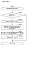
ここで、各構成要素について説明する前に、本実施形態に係るぱちんこ遊技機の特徴(概略)を説明する。以下、図面を参照しながら、各要素について詳述する。
(This Embodiment)
Here, before explaining each component, the features (outline) of the pachinko gaming machine according to the present embodiment will be described. Hereinafter, each element will be described in detail with reference to the drawings.
尚、以下の実施形態におけるステップ番号、符号、手段名等は、他の実施形態におけるステップ番号、符号、手段名等と同一である場合があるが、これらはそれぞれ単独の実施形態におけるステップ番号、符号、手段名等であることを示している(例えば、本実施形態におけるステップ2102と第2実施形態におけるステップ2102は、別の実施形態におけるステップ2102であるため、それぞれ単独で機能する処理である)。 The step numbers, codes, means names, etc. in the following embodiments may be the same as the step numbers, codes, means names, etc. in other embodiments, but these are the step numbers, codes, means names, etc. in their respective embodiments. It indicates that it is a code, a means name, or the like (for example, since step 2102 in the present embodiment and step 2102 in the second embodiment are steps 2102 in another embodiment, they are processes that function independently. ).
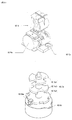
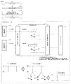
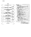
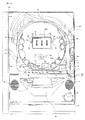
まず、図1を参照しながら、本実施形態に係るぱちんこ遊技機の前面側の基本構造を説明する。ぱちんこ遊技機は、主に遊技機枠と遊技盤D35で構成される。以下、これらを順に説明する。 First, with reference to FIG. 1, the basic structure on the front side of the pachinko gaming machine according to the present embodiment will be described. The pachinko gaming machine is mainly composed of a gaming machine frame and a gaming board D35. Hereinafter, these will be described in order.
はじめに、ぱちんこ遊技機の遊技機枠は、外枠D12、前枠D14、透明板D16、扉D18、上球皿D20、下球皿D22及び発射ハンドルD44を含む。まず、外枠D12は、ぱちんこ遊技機を設置すべき位置に固定するための枠体である。前枠D14は、外枠D12の開口部分に整合する枠体であり、図示しないヒンジ機構を介して外枠D12に開閉可能に取り付けられる。前枠D14は、遊技球を発射する機構、遊技盤D35を着脱可能に収容させるための機構、遊技球を誘導又は回収するための機構等を含む。透明板D16は、ガラス等により形成され、扉D18により支持される。扉D18は、図示しないヒンジ機構を介して前枠D14に開閉可能に取り付けられる。上球皿D20は、遊技球の貯留、発射レ−ルへの遊技球の送り出し、下球皿D22への遊技球の抜き取り等の機構を有する。下球皿D22は、遊技球の貯留、抜き取り等の機構を有する。また、遊技盤D35の右上方と左上方とにはスピーカD24が設けられており、遊技状態等に応じた効果音が出力される。 First, the gaming machine frame of the pachinko gaming machine includes an outer frame D12, a front frame D14, a transparent plate D16, a door D18, an upper ball plate D20, a lower ball plate D22, and a firing handle D44. First, the outer frame D12 is a frame body for fixing the pachinko gaming machine at a position where it should be installed. The front frame D14 is a frame body that matches the opening portion of the outer frame D12, and is attached to the outer frame D12 so as to be openable and closable via a hinge mechanism (not shown). The front frame D14 includes a mechanism for launching a game ball, a mechanism for detachably accommodating a game board D35, a mechanism for guiding or collecting a game ball, and the like. The transparent plate D16 is formed of glass or the like and is supported by the door D18. The door D18 is openably and closably attached to the front frame D14 via a hinge mechanism (not shown). The upper ball plate D20 has a mechanism for storing the game balls, sending the game balls to the launch rail, and extracting the game balls from the lower ball plate D22. The lower ball plate D22 has a mechanism for storing and extracting game balls. Further, speakers D24 are provided on the upper right and upper left of the game board D35, and sound effects corresponding to the game state and the like are output.
遊技盤D35と遊技機の前面の透明板D16(例えば、ガラス板)とは、13mmを超え25mmを超えない距離(本例では、19mm)の距離を保ち並行になるように遊技機枠に取り付けられている。ここで、遊技盤D35は、容易に動揺しないように固定機構によってしっかりと固定されている。 The game board D35 and the transparent plate D16 (for example, a glass plate) on the front surface of the game machine are attached to the game machine frame so as to maintain a distance of more than 13 mm and not more than 25 mm (19 mm in this example) and to be parallel to each other. Has been done. Here, the game board D35 is firmly fixed by a fixing mechanism so as not to be easily shaken.
また、透明板D16(例えば、ガラス板)は、遊技盤の全体の構造の見通しを妨げず、遊技盤上の遊技球の位置を確認できるように遊技領域全体が無色透明で凹凸がないように形成されている。 Further, the transparent plate D16 (for example, a glass plate) does not obstruct the view of the entire structure of the game board, and the entire game area is colorless and transparent so that the position of the game ball on the game board can be confirmed so that there is no unevenness. It is formed.
球皿(例えば、上球皿D20、下球皿D22)は、球皿上の遊技球が遊技者にとって可視的(遊技球の数を概ね確認可能)であり、遊技者が受け皿に受けた遊技球の取り出しを阻害しないような形状(遊技球を自由に取り出せるような形状)になっている。 In the ball plate (for example, upper ball plate D20, lower ball plate D22), the game balls on the ball plate are visible to the player (the number of game balls can be roughly confirmed), and the game received by the player in the saucer. It has a shape that does not hinder the taking out of the ball (a shape that allows the game ball to be taken out freely).
次に、遊技盤D35は、外レールD32と内レールD34とにより区画された遊技領域D30が形成されており、透明板D16を介して遊技盤D35上(遊技領域D30上)を流下する遊技球の位置を確認できるようになっている。遊技領域D30は、左打ち領域DL10と右打ち領域DR10とに大別される。そして、当該遊技領域D30には、図示しない複数の遊技釘及び風車等の機構や各種一般入賞口の他、左打ちルートML10、右打ちルートMR10、第1主遊技始動口A10、第2主遊技始動口B10、補助遊技始動口H10、第1大入賞口C10、第2大入賞口C20、第1主遊技図柄表示装置A20、第2主遊技図柄表示装置B20、演出表示装置SG、補助遊技図柄表示装置H20、センター飾りD38、可動体役物YK、右一般入賞口用ランプLP10、左一般入賞口P10、右一般入賞口P20、サブ入力ボタンSB及びアウト口D36が設置されている。尚、本実施形態においては、左打ちルートML10を第1流下ルートと称することがあり、右打ちルートMR10を第2流下ルートと称することがある。以下、各要素を順番に詳述する。 Next, in the game board D35, a game area D30 divided by an outer rail D32 and an inner rail D34 is formed, and a game ball that flows down on the game board D35 (on the game area D30) via the transparent plate D16. You can check the position of. The game area D30 is roughly divided into a left-handed area DL10 and a right-handed area DR10. Then, in the game area D30, in addition to mechanisms such as a plurality of game nails and windmills (not shown) and various general winning openings, a left-handed route ML10, a right-handed route MR10, a first main game starting port A10, and a second main game Starting port B10, auxiliary game starting port H10, first big winning opening C10, second big winning opening C20, first main game symbol display device A20, second main game symbol display device B20, effect display device SG, auxiliary game symbol A display device H20, a center decoration D38, a movable body accessory YK, a right general winning opening lamp LP10, a left general winning opening P10, a right general winning opening P20, a sub input button SB, and an out opening D36 are installed. In the present embodiment, the left-handed route ML10 may be referred to as a first flow-down route, and the right-handed route MR10 may be referred to as a second flow-down route. Hereinafter, each element will be described in detail in order.
次に、第1主遊技始動口A10は、第1主遊技に対応する始動入賞口として設置されている。具体的構成としては、第1主遊技始動口A10は、第1主遊技始動口入球検出装置A11sを備える。ここで、第1主遊技始動口入球検出装置A11sは、第1主遊技始動口A10への遊技球の入球を検出するセンサであり、入球時にその入球を示す第1主遊技始動口入球情報を生成する。 Next, the first main game start port A10 is installed as a start winning opening corresponding to the first main game. As a specific configuration, the first main game start port A10 includes a first main game start port entry ball detection device A11s. Here, the first main game start port entry detection device A11s is a sensor that detects the entry of a game ball into the first main game start port A10, and the first main game start indicating the entry at the time of entry. Generates mouth ball information.
次に、第2主遊技始動口B10は、第2主遊技に対応する始動入賞口として設置されている。具体的構成としては、第2主遊技始動口B10は、第2主遊技始動口入球検出装置B11sと、第2主遊技始動口電動役物B11dと、を備える。ここで、第2主遊技始動口入球検出装置B11sは、第2主遊技始動口B10への遊技球の入球を検出するセンサであり、入球時にその入球を示す第2主遊技始動口入球情報を生成する。次に、第2主遊技始動口電動役物B11dは、第2主遊技始動口B10に遊技球が入賞し難い閉鎖状態と当該閉鎖状態よりも遊技球が入賞し易い開放状態に可変する。 Next, the second main game start port B10 is installed as a start winning opening corresponding to the second main game. As a specific configuration, the second main game start port B10 includes a second main game start port entry ball detection device B11s and a second main game start port electric accessory B11d. Here, the second main game start port entry detection device B11s is a sensor that detects the entry of the game ball into the second main game start port B10, and the second main game start indicating the entry at the time of entry. Generates mouth ball information. Next, the second main game start port electric accessory B11d is variable to a closed state in which the game ball is hard to win in the second main game start port B10 and an open state in which the game ball is easier to win than the closed state.
ここで、本実施形態においては、第1主遊技始動口A10と第2主遊技始動口B10とが設けられており、遊技領域D30の左側(左打ち領域DL10)を流下する遊技球とが第1主遊技始動口A10に誘導され易い一方、遊技領域D30の右側(右打ち領域DR10)を流下する遊技球は第1主遊技始動口A10に誘導され難いよう構成されている。また、遊技領域D30の左側を流下する遊技球と遊技領域D30の右側を流下する遊技球とのいずれも第2主遊技始動口B10に誘導され得るよう構成されている。 Here, in the present embodiment, the first main game start port A10 and the second main game start port B10 are provided, and the game ball flowing down the left side of the game area D30 (left-handed area DL10) is the first. While it is easy to be guided to the first main game start port A10, the game ball flowing down the right side of the game area D30 (right-handed area DR10) is not easily guided to the first main game start port A10. Further, both the game ball flowing down the left side of the game area D30 and the game ball flowing down the right side of the game area D30 are configured to be guided to the second main game start port B10.
尚、本実施形態では、第2主遊技始動口B10側に電動役物を設けるよう構成したが、これには限定されず、第1主遊技始動口A10側に電動役物を設けるよう構成してもよい。更には、本実施形態では、第1主遊技始動口A10と第2主遊技始動口B10とが重ねるように配置されているが、これにも限定されず、第1主遊技始動口A10と第2主遊技始動口B10とを離隔して配置してもよい。 In the present embodiment, the electric accessory is provided on the second main game start port B10 side, but the present invention is not limited to this, and the electric accessory is provided on the first main game start port A10 side. You may. Further, in the present embodiment, the first main game start port A10 and the second main game start port B10 are arranged so as to overlap each other, but the present invention is not limited to this, and the first main game start port A10 and the first main game start port A10 are arranged so as to overlap each other. 2 The main game start port B10 may be separated from the main game start port B10.
次に、補助遊技始動口H10は、補助遊技始動口入球検出装置H11sを備える。ここで、補助遊技始動口入球検出装置H11sは、補助遊技始動口H10への遊技球の入球を検出するセンサであり、入球時にその入球を示す補助遊技始動口入球情報を生成する。尚、補助遊技始動口H10への遊技球の入球は、第2主遊技始動口B10の第2主遊技始動口電動役物B11dを拡開させるための抽選の契機となる。 Next, the auxiliary game start port H10 includes an auxiliary game start port entry ball detection device H11s. Here, the auxiliary game start port entry detection device H11s is a sensor that detects the entry of the game ball into the auxiliary game start opening H10, and generates the auxiliary game start opening entry information indicating the entry at the time of entry. To do. The entry of the game ball into the auxiliary game start port H10 triggers a lottery for expanding the second main game start port electric accessory B11d of the second main game start port B10.
ここで、本実施形態においては、遊技領域D30の右側(遊技領域中央を基準)を流下する遊技球が補助遊技始動口H10に誘導され易く、遊技領域D30の左側(遊技領域中央を基準)を流下する遊技球が補助遊技始動口H10に誘導され難くなるよう構成されている。但し、これには限定されず、遊技領域D30の右側及び左側(遊技領域中央を基準)を流下する遊技球が、補助遊技始動口H10に誘導され得るよう構成されていてもよい。 Here, in the present embodiment, the game ball flowing down the right side of the game area D30 (based on the center of the game area) is easily guided to the auxiliary game start port H10, and the left side of the game area D30 (referenced to the center of the game area) is used. It is configured so that the flowing game ball is less likely to be guided to the auxiliary game start port H10. However, the present invention is not limited to this, and a game ball flowing down the right side and the left side of the game area D30 (based on the center of the game area) may be configured to be guided to the auxiliary game start port H10.
次に、左一般入賞口P10は、左一般入賞口入球検出装置P11sを備える。左一般入賞口入球検出装置P11sは、左一般入賞口P10への遊技球の入球を検出するセンサであり、入球時にその入球を示す左一般入賞口入球情報を生成する。尚、左一般入賞口P10への遊技球の入球によって、所定数(例えば、3球)の遊技球が賞球として払い出されることとなる。尚、遊技領域D30の左側(遊技領域中央を基準)を流下する遊技球は左一般入賞口P10に入球し易く、遊技領域D30の右側(遊技領域中央を基準)を流下する遊技球は左一般入賞口P10に入球し難いよう構成されている。即ち、左打ち(遊技領域D30の左側である左打ち領域DL10(左打ちルートML10)を遊技球が流下するよう、遊技球の発射強度を調節して遊技球を打ち出すこと)を実行した際に左一般入賞口P10に入球し易いよう構成されている。 Next, the left general winning opening P10 includes a left general winning opening ball detection device P11s. The left general winning opening ball detection device P11s is a sensor that detects the entry of a game ball into the left general winning opening P10, and generates left general winning opening entry information indicating the entry at the time of entry. A predetermined number (for example, 3 balls) of game balls will be paid out as prize balls by entering the game balls into the left general prize opening P10. It should be noted that the game ball flowing down the left side of the game area D30 (based on the center of the game area) is easy to enter the left general winning opening P10, and the game ball flowing down the right side of the game area D30 (based on the center of the game area) is on the left. It is configured so that it is difficult to enter the general winning opening P10. That is, when the left-handed hit (the launching intensity of the game ball is adjusted so that the game ball flows down the left-handed hit area DL10 (left-handed route ML10) on the left side of the game area D30) is executed. It is configured so that it is easy to enter the left general winning opening P10.
次に、右一般入賞口P20は、右一般入賞口入球検出装置P21sを備える。右一般入賞口入球検出装置P21sは、右一般入賞口P20への遊技球の入球を検出するセンサであり、入球時にその入球を示す右一般入賞口入球情報を生成する。ここで、右一般入賞口P20は、右打ち領域DR10に配置され、補助遊技乱数を取得するという補助遊技始動口の役割と、賞球が払い出されるという一般入賞口の役割との双方を兼ね備えている。つまり、右一般入賞口P20への遊技球の入球は、第2主遊技始動口B10に取り付けられた第2主遊技始動口電動役物B11dを拡開させるための抽選の契機となる。また、右一般入賞口P20への遊技球の入球によって、所定数(例えば、2球)の遊技球が賞球として払い出されることとなる。尚、右一般入賞口P20への遊技球の入球によって、右一般入賞口P20から賞球として払い出される遊技球(例えば、2球)は、左一般入賞口P10への遊技球の入球によって、左一般入賞口P10から賞球として払い出される遊技球(例えば、3球)よりも少なくなるよう構成されている。尚、本実施形態においては、右打ちを実行した遊技球が右一般入賞口P20に入球し得るよう構成されている。即ち、右打ち(遊技領域D30の右側である右打ち領域DR10(右打ちルートMR10)を遊技球が流下するよう、遊技球の発射強度を調節して遊技球を打ち出すこと)を実行した際に右一般入賞口P20に入球し易いよう構成されている。 Next, the right general winning opening P20 includes a right general winning opening ball detection device P21s. The right general winning opening ball detection device P21s is a sensor that detects the entry of a game ball into the right general winning opening P20, and generates right general winning opening entry information indicating the entry at the time of entry. Here, the right general winning opening P20 is arranged in the right-handed area DR10, and has both the role of the auxiliary game starting opening for acquiring the auxiliary game random number and the role of the general winning opening for paying out the prize ball. There is. That is, the entry of the game ball into the right general winning opening P20 triggers a lottery for expanding the second main game starting port electric accessory B11d attached to the second main game starting port B10. In addition, a predetermined number (for example, 2 balls) of game balls will be paid out as prize balls by entering the game balls into the right general winning opening P20. The game balls (for example, 2 balls) paid out as prize balls from the right general winning opening P20 by the entry of the game ball into the right general winning opening P20 are determined by the entry of the game ball into the left general winning opening P10. , It is configured to be less than the game balls (for example, 3 balls) paid out as prize balls from the left general winning opening P10. In this embodiment, the game ball that has been hit right can enter the right general winning opening P20. That is, when right-handed (to launch the game ball by adjusting the firing intensity of the game ball so that the game ball flows down the right-handed area DR10 (right-handed route MR10) on the right side of the game area D30) is executed. It is configured so that it is easy to enter the right general winning opening P20.
ここで、本実施形態においては、右打ちを実行した際に入球し得る入球口としては、上流から順に、「補助遊技始動口H10→右一般入賞口P20→第2大入賞口C20→第1大入賞口C10→第2主遊技始動口B10→アウト口D36」の順となっている。また、補助遊技始動口H10はゲートの形状をしているため、補助遊技始動口H10を通過した遊技球は遊技領域上を更に流下していくこととなり、下流にある入球口(上述した右一般入賞口P20等)に入球し得ることとなる。一方、右一般入賞口P20に入球した遊技球は遊技盤面奥側に流入することとなり、その後第1大入賞口C10や第2大入賞口C20に入球することはない(右打ちを実行して右一般入賞口P20に入球しなかった遊技球が第1大入賞口C10又は第2大入賞口C20に入球し得ることとなる)。 Here, in the present embodiment, as the entry ports that can be entered when the right-handed hit is executed, in order from the upstream, "auxiliary game start opening H10 → right general winning opening P20 → second major winning opening C20 → The order is as follows: 1st big winning opening C10 → 2nd main game starting opening B10 → out opening D36 ”. Further, since the auxiliary game start port H10 has the shape of a gate, the game ball that has passed through the auxiliary game start port H10 will further flow down on the game area, and the ball entry port located downstream (the above-mentioned right). It will be possible to enter the general winning opening P20, etc.). On the other hand, the game ball that has entered the right general winning opening P20 will flow into the back side of the game board surface, and will not subsequently enter the first major winning opening C10 or the second major winning opening C20 (right-handed execution is performed). Then, the game ball that did not enter the right general winning opening P20 can enter the first large winning opening C10 or the second large winning opening C20).
尚、非時間短縮遊技状態における左打ちの実行時には(非時間短縮遊技状態においては左打ちにて遊技を進行する)、補助遊技始動口H10(及び右一般入賞口P20)に遊技球が入球し難いため第2主遊技始動口電動役物B11dが開放し難く、主遊技側の始動口として主に第1主遊技始動口A10への入球によって遊技を進行していくこととなり、一方、時間短縮遊技状態における右打ちの実行時には(時間短縮遊技状態においては右打ちにて遊技を進行する)、補助遊技始動口H10(及び右一般入賞口P20)に遊技球が入球し易いため第2主遊技始動口電動役物B11dが開放し易く、主遊技側の始動口として主に第2主遊技始動口B10への入球によって遊技を進行していくこととなる。また、非時間短縮遊技状態において左打ちにて遊技球を発射し続けた場合の第1主遊技始動口A10への入球容易性よりも、時間短縮遊技状態において右打ちにて遊技球を発射し続けた場合の第2主遊技始動口B10への入球容易性の方が高い、換言すると、非時間短縮遊技状態において左打ちにて遊技球を発射し続けた場合の第1主遊技始動口A10又は第2主遊技始動口B10への入球容易性よりも、時間短縮遊技状態において右打ちにて遊技球を発射し続けた場合の第1主遊技始動口A10又は第2主遊技始動口B10への入球容易性の方が高くなる。そこで、本例においては、左打ち実行時の方が右打ち実行時よりも入球し易い左一般入賞口P10に入球した際の賞球数(本例では、3球)を、右打ち実行時の方が左打ち実行時よりも入球し易い右一般入賞口P20に入球した際の賞球数(本例では、2球)よりも多く設計することにより、非時間短縮遊技状態にて左打ちで遊技を進行した場合と、時間短縮遊技状態にて右打ちで遊技を進行した場合との、入賞口へ入球することにより払い出される平均の賞球数の差分、即ち、ベース値(特別遊技に当選していない状況において、発射した遊技球100球に対する、払い出される賞球払出数の期待値)の差分が大きくなりすぎることを防止することができる。 When the left-handed player is executed in the non-time-reduced game state (the game proceeds by left-handed player in the non-time-reduced game state), the game ball enters the auxiliary game start opening H10 (and the right general winning opening P20). The second main game start port electric accessory B11d is difficult to open because it is difficult to open, and the game proceeds mainly by entering the first main game start port A10 as the start port on the main game side. When right-handed is executed in the time-reduced game state (the game is advanced by right-handed in the time-reduced game state), the game ball easily enters the auxiliary game start opening H10 (and the right general winning opening P20). 2 Main game start port The electric accessory B11d is easy to open, and the game proceeds mainly by entering the second main game start port B10 as the start port on the main game side. In addition, the game ball is launched by right-handed in the time-reduced game state, rather than the ease of entering the first main game start port A10 when the game ball is continuously fired by left-handed in the non-time-reduced game state. It is easier to enter the second main game start port B10 when the game is continued, in other words, the first main game starts when the game ball is continuously launched by left-handed in the non-time shortened game state. Rather than the ease of entering the mouth A10 or the second main game start port B10, the first main game start port A10 or the second main game start when the game ball is continuously launched by right-handed in the game state where the time is shortened. The ease of entering the ball into the mouth B10 is higher. Therefore, in this example, the number of prize balls (3 balls in this example) when the ball is entered into the left general winning opening P10, which is easier to enter when the left-handed hit is executed, is right-handed. Non-time reduction game state by designing more than the number of prize balls (2 balls in this example) when entering the right general winning opening P20, which is easier to enter during execution than when executing left-handed The difference between the average number of winning balls paid out by entering the winning opening, that is, the base, between the case where the game is played with a left-handed hit and the case where the game is played with a right-handed hit in a time-saving game state. It is possible to prevent the difference between the values (the expected value of the number of prize balls to be paid out with respect to the 100 game balls fired in the situation where the special game is not won) becomes too large.
また、右一般入賞口用ランプLP10は、例えば、液晶、LED等で構成されており、特別遊技の実行中に右一般入賞口に遊技球が入球することにより点灯し得るよう構成されている。また、詳細は後述することとなるが、右一般入賞口用ランプLP10の点灯色の違いにより特別遊技終了後に確率変動遊技状態に移行するか非確率変動遊技状態に移行するかを示唆し得るよう構成されている。尚、右一般入賞口用ランプLP10は、遊技領域D30上の、左打ち領域DL10に設けても良いし右打ち領域DR10に設けても良い。また、遊技領域D30以外の領域に設けてもよい。 Further, the right general winning opening lamp LP10 is composed of, for example, a liquid crystal, an LED, or the like, and is configured to be lit when a game ball enters the right general winning opening during execution of a special game. .. Further, although the details will be described later, it may be suggested whether to shift to the probability-variable gaming state or the non-probability-variable gaming state after the end of the special game depending on the difference in the lighting color of the right general winning opening lamp LP10. It is configured. The right general winning opening lamp LP10 may be provided in the left-handed area DL10 or the right-handed area DR10 on the game area D30. Further, it may be provided in an area other than the game area D30.
また、右打ちルートMR10を流下した遊技球は、右打ちルート流出口D50を通過して右一般入賞口P20、第1大入賞口C10、第2大入賞口C20等の近傍に流下していくこととなる。 In addition, the game ball that has flowed down the right-handed route MR10 passes through the right-handed route outlet D50 and flows down to the vicinity of the right general winning opening P20, the first major winning opening C10, the second major winning opening C20, and the like. It will be.
次に、アウト口D36の右上方には、第1大入賞口C10と第2大入賞口C20とが設けられており、遊技領域D30の右側(遊技領域中央を基準)を流下する遊技球は、アウト口D36に到達する前に、第1大入賞口C10及び第2大入賞口C20が配置されている領域を通過し易いよう構成されている。 Next, the first big winning opening C10 and the second big winning opening C20 are provided on the upper right of the out opening D36, and the game ball flowing down the right side of the game area D30 (based on the center of the game area) , It is configured to easily pass through the area where the first special winning opening C10 and the second big winning opening C20 are arranged before reaching the out opening D36.
次に、第1大入賞口C10は、第1主遊技図柄(特別図柄)又は第2主遊技図柄(特別図柄)が大当り図柄停止した場合に開状態となる、横長方形状を成しアウト口D36の右上方に位置した、主遊技に対応した入賞口である。具体的構成としては、第1大入賞口C10は、遊技球の入球を検出するための第1大入賞口入賞検出装置C11sと、第1大入賞口電動役物C11d{及び第1大入賞口電動役物ソレノイドC13}と、を備える。ここで、第1大入賞口入賞検出装置C11sは、第1大入賞口C10への遊技球の入球を検出するセンサであり、入球時にその入球を示す第1大入賞口入球情報を生成する。第1大入賞口電動役物C11dは、第1大入賞口C10に遊技球が入賞不能又は入賞困難な通常状態と遊技球が入賞し易い開放状態に第1大入賞口C10を可変させる(第1大入賞口電動役物ソレノイドC13を励磁して可変させる)。尚、本実施形態では、大入賞口の態様を、横長方形状を成し遊技球が入賞不能又は入賞困難な通常状態と遊技球が入賞し易い開放状態とに可変させる態様としているが、これには限定されない。その場合には、例えば、大入賞口内に設けられた棒状部材が遊技者側に突き出した状態である進出状態と遊技者側に対して引っ込んだ状態である退避状態とを採り得る態様(いわゆる、ベロ型アタッカ−)や、遊技球が転動可能な通路上の開口部を大入賞口とし、当該開口部を閉鎖する状態と開放する状態とを採り得る態様(いわゆる、スライド式アタッカー)としてもよく、大入賞口への入球数を所定数(例えば、10個)とすることを担保したい場合において好適である。 Next, the first big winning opening C10 has a horizontal rectangular shape and is an out opening that opens when the first main game symbol (special symbol) or the second main game symbol (special symbol) stops the big hit symbol. It is a winning opening corresponding to the main game, located on the upper right side of D36. As a specific configuration, the first large winning opening C10 includes a first large winning opening winning detection device C11s for detecting the entry of a game ball, a first large winning opening electric accessory C11d {and a first large winning opening. The mouth electric accessory solenoid C13} is provided. Here, the first large winning opening winning detection device C11s is a sensor that detects the entry of a game ball into the first large winning opening C10, and the first large winning opening entry information indicating the entry at the time of entry. To generate. The first large winning opening electric accessory C11d changes the first large winning opening C10 into a normal state in which the game ball cannot or is difficult to win in the first large winning opening C10 and an open state in which the game ball is easy to win (the first). 1 Grand prize opening Electric accessory solenoid C13 is excited and changed). In the present embodiment, the mode of the large winning opening is changed to a normal state in which the game ball cannot win or is difficult to win in a horizontal rectangular shape and an open state in which the game ball is easy to win. Not limited to. In that case, for example, an advanced state in which the rod-shaped member provided in the large winning opening is projected toward the player side and a retracted state in which the rod-shaped member is retracted toward the player side can be adopted (so-called so-called). A tongue-type attacker) or an opening on the passage where the game ball can roll is used as a big winning opening, and the opening can be closed or opened (so-called sliding attacker). It is often suitable when it is desired to ensure that the number of balls entered into the large winning opening is a predetermined number (for example, 10).
次に、第2大入賞口C20は、第1主遊技図柄(特別図柄)又は第2主遊技図柄(特別図柄)が大当り図柄で停止した場合に開状態となる、横長方形状を成しアウト口D36の右上方に位置した、主遊技に対応した入賞口である。具体的構成としては、第2大入賞口C20は、遊技球の入球を検出するための第2大入賞口入賞検出装置C21sと、第2大入賞口電動役物C21d{及び第2大入賞口電動役物ソレノイドC23}と、を備える。ここで、第2大入賞口入賞検出装置C21sは、第2大入賞口C20への遊技球の入球を検出するセンサであり、入球時にその入球を示す第2大入賞口入球情報を生成する。そして、第2大入賞口C20内に入球した遊技球は、第2大入賞口入賞検出装置C21sによって検出されるよう構成されている。次に、第2大入賞口電動役物C21dは、第2大入賞口C20に遊技球が入賞不能又は入賞困難な通常状態と遊技球が入賞し易い開放状態とに第2大入賞口C20を可変させる。尚、本実施形態では、大入賞口の態様を、横長方形状を成し遊技球が入賞不能又は入賞困難な通常状態と遊技球が入賞し易い開放状態とに可変させる態様としているが、これには限定されない。その場合には、例えば、大入賞口内に設けられた棒状部材が遊技者側に突き出した状態である進出状態と遊技者側に対して引っ込んだ状態である退避状態とを採り得る態様(いわゆる、ベロ型アタッカー)や、遊技球が転動可能な通路上の開口部を大入賞口とし、当該開口部を閉鎖する状態と開放する状態とを採り得る態様(いわゆる、スライド式アタッカー)としてもよく、大入賞口への入球数を所定数(例えば、10個)とすることを担保したい場合において好適である。 Next, the second big winning opening C20 forms a horizontal rectangular shape and goes out, which is opened when the first main game symbol (special symbol) or the second main game symbol (special symbol) stops at the jackpot symbol. It is a winning opening corresponding to the main game, located on the upper right side of the opening D36. As a specific configuration, the second special winning opening C20 includes a second large winning opening winning detection device C21s for detecting the entry of a game ball, a second large winning opening electric accessory C21d {and a second large winning opening. The mouth electric accessory solenoid C23} is provided. Here, the second large winning opening winning detection device C21s is a sensor that detects the entry of a game ball into the second large winning opening C20, and the second large winning opening entry information indicating the entry at the time of entry. To generate. Then, the game ball that has entered the second special winning opening C20 is configured to be detected by the second large winning opening winning detection device C21s. Next, the second big winning opening electric accessory C21d has the second big winning opening C20 in the normal state where the game ball cannot win or is difficult to win in the second big winning opening C20 and the open state where the game ball is easy to win. Make it variable. In the present embodiment, the mode of the large winning opening is changed to a normal state in which the game ball cannot win or is difficult to win in a horizontal rectangular shape and an open state in which the game ball is easy to win. Not limited to. In that case, for example, an advance state in which the rod-shaped member provided in the large winning opening is projected toward the player side and a retracted state in which the rod-shaped member is retracted toward the player side can be adopted (so-called so-called). A tongue-type attacker) or an opening on the passage where the game ball can roll is used as a large winning opening, and the opening may be closed or opened (so-called sliding attacker). , It is suitable when it is desired to ensure that the number of balls entered into the large winning opening is a predetermined number (for example, 10).
次に、第1主遊技図柄表示装置A20(第2主遊技図柄表示装置B20)は、第1主遊技(第2主遊技)に対応する第1主遊技図柄(第2主遊技図柄)に関連した表示等を実行する装置である。具体的構成としては、第1主遊技図柄表示装置A20(第2主遊技図柄表示装置B20)は、第1主遊技図柄表示部A21g(第2主遊技図柄表示部B21g)と、第1主遊技図柄保留表示部A21h(第2主遊技図柄保留表示部B21h)とを備える。ここで、第1主遊技図柄保留表示部A21h(第2主遊技図柄保留表示部B21h)は、4個のランプから構成され、当該ランプの点灯個数が、第1主遊技(第2主遊技)に係る乱数の保留数(実行されていない主遊技図柄の変動数)に相当する。尚、第1主遊技図柄表示部A21g(第2主遊技図柄表示部B21g)は、例えば7セグメントLEDで構成され、第1主遊技図柄(第2主遊技図柄)は、「0」〜「9」の10種類の数字及びハズレの「−」で表示される{但し、これには限定されず、いずれの主遊技図柄が表示されたのかを遊技者が認識困難となるよう、7セグメントLEDを用いて記号等によって表示することが好適である。また、保留数表示においても、4個のランプから構成されていることには限定されず、最大4個分の保留数を表示可能に構成(例えば、1個のランプから構成されており、保留数1:点灯、保留数2:低速点滅、保留数3:中速点滅、保留数4:高速点滅、するよう構成)されていればよい}。 Next, the first main game symbol display device A20 (second main game symbol display device B20) is related to the first main game symbol (second main game symbol) corresponding to the first main game (second main game). It is a device that executes the displayed display. As a specific configuration, the first main game symbol display device A20 (second main game symbol display device B20) includes a first main game symbol display unit A21g (second main game symbol display unit B21g) and a first main game symbol display unit B21g. It is provided with a symbol holding display unit A21h (second main game symbol holding display unit B21h). Here, the first main game symbol hold display unit A21h (second main game symbol hold display unit B21h) is composed of four lamps, and the number of lamps lit is the first main game (second main game). Corresponds to the number of pending random numbers related to (the number of fluctuations in the main game symbol that has not been executed). The first main game symbol display unit A21g (second main game symbol display unit B21g) is composed of, for example, a 7-segment LED, and the first main game symbol (second main game symbol) is "0" to "9". It is displayed with 10 kinds of numbers of "" and "-" of the loss {However, it is not limited to this, and the 7-segment LED is displayed so that it becomes difficult for the player to recognize which main game symbol is displayed. It is preferable to use and display by a symbol or the like. Further, the holding number display is not limited to being composed of four lamps, and can display a maximum of four holding numbers (for example, it is composed of one lamp and is held. Number 1: Lighting, Hold number 2: Low speed blinking, Hold number 3: Medium speed blinking, Hold number 4: High speed blinking).
尚、主遊技図柄は必ずしも演出的な役割を持つ必要が無いため、本実施形態では、第1主遊技図柄表示装置A20の大きさは、目立たない程度に設定されている。しかしながら、主遊技図柄自体に演出的な役割を持たせて装飾図柄を表示させないような手法を採用する場合には、後述する演出表示装置SGのような液晶ディスプレーに、主遊技図柄を表示させるように構成してもよい。 Since the main game symbol does not necessarily have to have a directing role, the size of the first main game symbol display device A20 is set to an inconspicuous degree in the present embodiment. However, in the case of adopting a method in which the main game symbol itself has a directing role and the decorative symbol is not displayed, the main game symbol is displayed on a liquid crystal display such as the effect display device SG described later. It may be configured as.
次に、演出表示装置SGは、主遊技図柄と連動して変動・停止する装飾図柄を含む演出画像の表示等を実行する装置である。ここで、具体的構成としては、演出表示装置SGは、装飾図柄の変動表示等を含めて演出が実行される表示領域SG10を備える。ここで、表示領域SG10は、例えば、スロットマシンのゲームを模した複数列の装飾図柄変動の動画像を表示する装飾図柄表示領域SG11と、主遊技保留情報を表示する第1保留表示部SG12及び第2保留表示部SG13と、を有している。尚、演出表示装置SGは、本実施形態では液晶ディスプレーで構成されているが、機械式のドラムやLED等の他の表示手段で構成されていてもよい。次に、第1保留表示部SG12及び第2保留表示部SG13は夫々4個のランプから構成され、当該ランプは、主遊技図柄の保留ランプと連動している。 Next, the effect display device SG is a device that displays an effect image including a decorative symbol that fluctuates and stops in conjunction with the main game symbol. Here, as a specific configuration, the effect display device SG includes a display area SG10 in which the effect is executed including the variable display of the decorative symbol. Here, the display area SG10 includes, for example, a decorative symbol display area SG11 for displaying a moving image of a plurality of rows of decorative symbol fluctuations imitating a game of a slot machine, a first hold display unit SG12 for displaying main game hold information, and the like. It has a second hold display unit SG13. Although the effect display device SG is composed of a liquid crystal display in this embodiment, it may be composed of other display means such as a mechanical drum or an LED. Next, the first hold display unit SG12 and the second hold display unit SG13 are each composed of four lamps, and the lamps are interlocked with the hold lamps of the main game symbol.
次に、補助遊技図柄表示装置H20は、補助遊技図柄に関する表示等を実行する装置である。具体的構成としては、補助遊技図柄表示装置H20は、補助遊技図柄表示部H21gと、補助遊技図柄保留表示部H21hとを備える。ここで、補助遊技図柄保留表示部H21hは、4個のランプから構成され、当該ランプの点灯個数が、補助遊技図柄変動の保留数(実行されていない補助遊技図柄変動の数)に相当する。本実施形態においては、補助遊技乱数を取得し得る入球口として、補助遊技始動口H10と右一般入賞口P20との2つの入球口を有しており、当該2つの入球口のいずれに入球した場合にも、取得した補助遊技乱数に関する表示は補助遊技図柄表示装置H20に表示されることとなる。 Next, the auxiliary game symbol display device H20 is a device that executes display and the like related to the auxiliary game symbol. As a specific configuration, the auxiliary game symbol display device H20 includes an auxiliary game symbol display unit H21g and an auxiliary game symbol hold display unit H21h. Here, the auxiliary game symbol hold display unit H21h is composed of four lamps, and the number of lighting of the lamps corresponds to the number of reserved auxiliary game symbol changes (the number of auxiliary game symbol changes that have not been executed). In the present embodiment, there are two entry ports, an auxiliary game start opening H10 and a right general winning opening P20, as entry openings from which auxiliary game random numbers can be acquired, and any of the two entry openings The display regarding the acquired auxiliary game random number will be displayed on the auxiliary game symbol display device H20 even when the ball is entered into the ball.
次に、センター飾りD38は、演出表示装置SGの周囲に設置され、遊技球の流路、演出表示装置SGの保護、装飾等の機能を有する。また、遊技効果ランプD26は、遊技領域D30及び/又は遊技領域D30以外の領域に設けられ、点滅等することで演出の役割を果たす。 Next, the center decoration D38 is installed around the effect display device SG, and has functions such as a flow path of the game ball, protection of the effect display device SG, and decoration. Further, the game effect lamp D26 is provided in an area other than the game area D30 and / or the game area D30, and plays a role of directing by blinking or the like.
次に、可動体役物YKは、演出表示装置SGの近傍に設置され、図柄変動に伴う演出実行の際に駆動して遊技を盛り上げる役割を担っている。上下方向に移動したり、回転駆動したり、点灯したりして、駆動したことが目立つよう構成し、且つ、大当り期待度の高い図柄変動にて駆動し易い構成することが好適である。 Next, the movable body accessory YK is installed in the vicinity of the effect display device SG, and plays a role of driving and enlivening the game when the effect is executed due to the symbol change. It is preferable that the device is moved in the vertical direction, driven by rotation, or lit so that the drive is conspicuous, and the drive is easy to drive due to a symbol variation with a high expectation of a big hit.
次に、サブ入力ボタンSBは、副制御基板Sと電気的に接続された、操作(押下)することによって当該操作に基づく演出が実行されることとなる操作部材である。尚、サブ入力ボタンSBの操作態様として、単発押し(短時間の1回のみサブ入力ボタンSBを押下する操作態様)と、連打(複数回サブ入力ボタンSBを押下する操作態様)と、長押し(所定期間サブ入力ボタンSBを押し続ける操作態様)と、を有するよう構成してもよい。また、副制御基板Sと電気的に接続された、操作(押下)することによって当該操作に基づく演出が実行されることとなる操作部材はサブ入力ボタンSBのみには限定されず、上、下、左、右の4つの操作部を有しており、当該操作部を操作することにより、実行する演出(予告演出等)を選択可能に構成される十字キー、手前に引くことにより演出(可動体役物が作動する、等)が実行されるレバー、等を有するよう構成してもよい。 Next, the sub-input button SB is an operation member that is electrically connected to the sub-control board S, and by operating (pressing), an effect based on the operation is executed. The operation modes of the sub-input button SB include a single press (an operation mode in which the sub-input button SB is pressed only once for a short time), repeated hits (an operation mode in which the sub-input button SB is pressed multiple times), and a long press. (Operation mode in which the sub-input button SB is continuously pressed for a predetermined period), and may be configured to have. Further, the operating members electrically connected to the sub-control board S and for which the effect based on the operation is executed by operating (pressing) are not limited to the sub-input button SB, but are up and down. It has four operation units, left and right, and a cross key that allows you to select the effect to be executed (notice effect, etc.) by operating the operation unit, and the effect (movable) by pulling it toward you. It may be configured to have a lever, etc. on which the body accessory operates, etc.).
次に、アウト口D36は、遊技領域D30の下方に設けられた入球口であり、遊技領域D30に設けられたいずれの入賞口にも入球せずに流下した遊技球が入球する入球口であり、アウト口D36に遊技球が入球した場合には、乱数に基づく各種抽選や入球に基づく賞球等は実行されず、当該遊技球は遊技機外に排出されることとなる。なお、本実施例では、が遊技盤上の最下部にのみ、入賞口に入賞しなかった遊技球が入るアウト口D36が設けられているが、遊技盤の上部の所定箇所にアウト口を設けることも可能である。その場合には、当該入口が入賞口でないことを明らかにするため、シールを用いて、「OUT」を表示する等、入賞口と混同しないようにすることが望ましい。 Next, the out port D36 is an entry port provided below the game area D30, and the game ball that has flowed down without entering any winning opening provided in the game area D30 enters the ball. It is a ball mouth, and when a game ball enters the out port D36, various lottery based on random numbers and prize balls based on the entering ball are not executed, and the game ball is discharged to the outside of the game machine. Become. In this embodiment, the out port D36 for entering the game ball that did not win the winning opening is provided only at the bottom of the game board, but the out opening is provided at a predetermined position on the upper part of the game board. It is also possible. In that case, in order to clarify that the entrance is not a winning opening, it is desirable not to be confused with the winning opening, such as by displaying "OUT" with a sticker.
尚、不図示であるが、遊技盤D35(遊技領域D30)の大きさは、一辺が500mmである正方形の枠を超えず、かつ、直径が300mmである円を含む範囲が設定されている。 Although not shown, the size of the game board D35 (game area D30) is set to include a circle having a diameter of 300 mm and not exceeding a square frame having a side of 500 mm.
また、本実施形態においては、役物が作動しない場合(大入賞口C10等の可変入賞口が閉鎖状態となっている場合)における入賞口(遊技球を入賞させることが可能なもの、換言すると発射された遊技球について物理的に可能な軌跡をもってしても入賞が不可能でないものであり、例えば、第1主遊技始動口A10)の数(入賞口の入口の数)は、5個(第1主遊技始動口A10が1個、左一般入賞口P10が3個、右一般入賞口P20が1個)となっている。尚、入賞口の数は適宜設定可能であるが、入賞割合と遊技の複雑化抑止の観点から5個〜15個の範囲が望ましい。ここで、入賞口の入口とは、入賞口及び当該入賞口に連なる遊技釘等(その間を遊技球が通過できない形で連続配置されている遊技釘等)で構成される遊技球の通過面のうち、入賞口から最も離れた位置にある部分を指す。尚、役物が作動しない場合における入賞口の入口の大きさ(入賞口の入口のうち、遊技盤D35と平行な距離の最大値であり、遊技釘により設定されている場合には釘と釘の内法)は、13mmを超えないように構成することが望ましく、大入賞口以外の可変入賞装置(電動役物や非電動役物)の入賞口の入口の大きさ(前述の通り)は、55mmを超えないことが望ましい。また、大入賞口の入口の大きさ(遊技盤と平行な距離の最大値)は、他の役物と区別するために、55mmを超え、135mmを超えないようにすることが望ましい。 Further, in the present embodiment, when the accessory does not operate (when the variable winning opening such as the large winning opening C10 is closed), the winning opening (the one capable of winning the game ball, in other words, It is not impossible to win a prize even if the launched game ball has a physically possible trajectory. For example, the number of the first main game start opening A10 (the number of entrances of the winning opening) is 5 (the number of entrances of the winning opening). The first main game start opening A10 is one, the left general winning opening P10 is three, and the right general winning opening P20 is one). The number of winning openings can be set as appropriate, but it is desirable that the number is in the range of 5 to 15 from the viewpoint of the winning ratio and the suppression of complication of the game. Here, the entrance of the winning opening is a passing surface of a game ball composed of the winning opening and a game nail or the like connected to the winning opening (a game nail or the like which is continuously arranged so that the game ball cannot pass between them). Of these, it refers to the part farthest from the winning opening. The size of the entrance of the winning opening when the accessory does not operate (the maximum value of the distance parallel to the game board D35 among the entrances of the winning opening, and when it is set by the game nail, the nail and the nail It is desirable to configure the method so that it does not exceed 13 mm, and the size of the entrance of the winning opening of the variable winning device (electric accessory or non-electric accessory) other than the large winning opening (as described above). It is desirable that it does not exceed 55 mm. In addition, it is desirable that the size of the entrance of the large winning opening (the maximum value of the distance parallel to the game board) exceeds 55 mm and does not exceed 135 mm in order to distinguish it from other accessories.
更に、普通図柄表示装置が作動する契機となっているゲート(例えば、補助遊技始動口H10)の大きさ(ゲート及び当該ゲートに連なる遊技釘等(その間を遊技球が通過できない形で連続配置されている遊技釘等)で構成される遊技球の通過面のうち、ゲートから最も離れた位置で遊技盤D35と平行な距離の最大値、即ち実質的なゲートの入口)は、13mmを超えないようにすることが望ましい。 Further, the size of the gate (for example, the auxiliary game start port H10) that normally triggers the operation of the symbol display device (the gate and the game nails connected to the gate (for example, the game balls are continuously arranged so that the game ball cannot pass between them). The maximum value of the distance parallel to the game board D35 at the position farthest from the gate, that is, the actual entrance of the gate) does not exceed 13 mm among the passing surfaces of the game balls composed of the game nails, etc. It is desirable to do so.
尚、本実施形態においては、大入賞口を2つ(第1大入賞口C10と第2大入賞口C20との2つ)設けているが、射幸性の観点から2個を超えないように構成することが望ましい。また、本実施形態のように、2個の大入賞口が開放等している否かにかかわらず物理的に明確に分離されていることが明らかな構造が望ましい。更に、本実施形態のように、2個の大入賞口が水平方向に隣接することなく、2つの大入賞口の間に遊技球が通過可能となっていることが望ましい。また、本実施形態では始動口として、第1主遊技始動口A10と第2主遊技始動口B20との2つが設けているが、一般入賞口の数(本実施形態においては一般入賞口が4個設けられている)とのバランスを考慮し、3個を超えないように構成することが望ましい。 In this embodiment, two large winning openings (two, the first large winning opening C10 and the second large winning opening C20) are provided, but from the viewpoint of gambling, the number should not exceed two. It is desirable to configure. Further, as in the present embodiment, it is desirable to have a structure in which it is clear that the two large winning openings are physically and clearly separated regardless of whether or not they are open. Further, as in the present embodiment, it is desirable that the game balls can pass between the two large winning openings without the two large winning openings being horizontally adjacent to each other. Further, in the present embodiment, two starting ports, a first main game starting port A10 and a second main game starting port B20, are provided, but the number of general winning openings (in this embodiment, the general winning opening is 4). In consideration of the balance with (provided of 3 pieces), it is desirable to configure so as not to exceed 3 pieces.
なお、始動口内に可動物を設け、既に始動口に入賞した遊技球の動きを当該可動物で変化させてもよい。この場合には、可動物は、常時一定の動作を継続(一連の動作を繰り返すものを含む。)させ、動作の調整が不可能な構成とすることが望ましい。 A movable object may be provided in the starting port, and the movement of the game ball that has already won a prize in the starting port may be changed by the movable object. In this case, it is desirable that the movable object has a structure in which a constant operation is constantly continued (including a device that repeats a series of operations) and the operation cannot be adjusted.
更に、前述の通り、遊技領域D30には、多数の遊技釘等が配置されているが、この配置は、遊技球の落下を一定の範囲で不規則にさせるものの、極端に不規則にしないことが望ましい。具体的には、電気的又はその他の動力(風車、その他の遊技球の落下の方向に変化を与えるための装置に遊技球が衝突したことにより、遊技球が落下の方向とは異なった方向に変化することを除く。)により遊技球を上昇させる装置(上昇させる程度がわずかであって、遊技球の落下の方向を著しく不規則にしないことが明らかなものを除く。)等は、発射した遊技球の順序と入賞口又はアウト口に入球する順序とが大きく相違する可能性があるため、このような装置は設けないことが望ましい。なお、遊技釘及び風車は、遊技板におおむね垂直(±5度程度)に打ち込まれている。また、いうまでもないが、遊技釘等その他遊技盤上に設ける構造物は遊技球の衝突により形状等が変化しない程度の耐久性(例えば、本例の遊技釘では、ビッカース硬度が150Hv〜230Hvの真鍮製を用いている。)が確保されている。 Further, as described above, a large number of game nails and the like are arranged in the game area D30, and although this arrangement causes the falling of the game ball to be irregular within a certain range, it should not be extremely irregular. Is desirable. Specifically, when the game ball collides with an electric or other power (windmill or other device for changing the fall direction of the game ball, the game ball moves in a direction different from the fall direction. Devices that raise the game ball by (excluding changes) (excluding those that raise the game ball only slightly and that clearly do not make the direction of the game ball fall significantly irregular), etc. were fired. Since the order of the game balls and the order of entering the winning or out opening may be significantly different, it is desirable not to provide such a device. The game nails and the windmill are driven into the game board approximately vertically (about ± 5 degrees). Needless to say, other structures such as game nails provided on the game board are durable enough that the shape and the like do not change due to the collision of the game balls (for example, the Vickers hardness of the game nail of this example is 150 Hv to 230 Hv). (Made of brass) is secured.
次に、図2を参照しながら、ぱちんこ遊技機の背面側における基本構造を説明する。ぱちんこ遊技機は、ぱちんこ遊技機の全体動作を制御し、特に第1主遊技始動口A10(第2主遊技始動口B10)へ入球したときの抽選等、遊技動作全般の制御(即ち、遊技者の利益と直接関係する制御)を行う主制御基板Mと、遊技内容に興趣性を付与する演出表示装置SG上での各種演出に係る表示制御等を行うサブメイン制御部SMと、主に演出表示を実行するサブサブ制御部SSと、所定のエラー発生時に点灯してエラー発生を報知するエラーランプSS3と、賞球タンクKT、賞球レールKR及び各入賞口への入賞に応じて賞球タンクKTから供給される遊技球を上球皿D20へ払い出す払出ユニットKE10等を備える賞球払出装置(セット基盤)KEと、所定のエラーを解除するためのエラー解除スイッチKH3aと、賞球払出ユニットKE10による払出動作を制御する賞球払出制御基板KHと、払出に係るエラーの発生状況を表示(例えば、7セグ表示)するエラー表示器KH3と、払出ユニットKE10による払出動作を制御する賞球払出制御基板KHと、上球皿D20の遊技球(貯留球)を遊技領域D30へ1球ずつ発射する発射装置D42と、発射装置D42の発射動作を制御する発射制御基板D40と、ぱちんこ遊技機の各部へ電力を供給する電源供給ユニットEと、ぱちんこ遊技機の電源をオン・オフするスイッチである電源スイッチEa等が、前枠D14裏面(遊技側と反対側)に設けられている。 Next, the basic structure on the back side of the pachinko gaming machine will be described with reference to FIG. The pachinko game machine controls the overall operation of the pachinko game machine, and controls the overall game operation (that is, the game) such as a lottery when the ball enters the first main game start port A10 (second main game start port B10). Mainly the main control board M that performs control that is directly related to the interests of the person, and the sub-main control unit SM that performs display control related to various effects on the effect display device SG that gives interest to the game content. The sub-sub control unit SS that executes the effect display, the error lamp SS3 that lights up when a predetermined error occurs and notifies the occurrence of the error, the prize ball tank KT, the prize ball rail KR, and the prize ball according to the prizes in each prize opening. A prize ball payout device (set base) KE equipped with a payout unit KE10 or the like for paying out game balls supplied from the tank KT to the upper ball plate D20, an error release switch KH3a for clearing a predetermined error, and a prize ball payout. The prize ball payout control board KH that controls the payout operation by the unit KE10, the error display KH3 that displays the occurrence status of the error related to the payout (for example, 7-segment display), and the prize ball that controls the payout operation by the payout unit KE10. The payout control board KH, the launch device D42 that launches the game balls (reservoir balls) of the upper ball plate D20 one by one to the game area D30, the launch control board D40 that controls the launch operation of the launch device D42, and the pachinko game machine. A power supply unit E for supplying power to each part of the front frame D14, a power switch Ea for turning on / off the power of the pachinko game machine, and the like are provided on the back surface of the front frame D14 (opposite side to the game side).
また、主制御基板M上には、第1主遊技始動口A10、第2主遊技始動口B10、左一般入賞口P10、右一般入賞口P20、第1大入賞口C10、第2大入賞口C20、等の入賞口への遊技球の入球状況を表示し得る入球状態表示装置J10が設けられており、4桁の8セグメント表示器が横一列に整列されて取り付けられている。尚、同図における入球状態表示装置J10は、主制御基板Mの遊技機の裏側方向の面に設けられており、遊技場側が所持している鍵で扉ユニットD18を解錠して扉ユニットD18を開放し、扉ユニットD18(遊技盤)の裏面に取り付けられた基板類を確認する必要があるので、遊技者は確認することができないよう構成されている。尚、入球状態表示装置J10に表示する前記入球状況の一例としては、総アウト個数による区間情報やベース比率(『(低確払出個数÷低確アウト個数)×100』で算出される値)等が挙げられる。尚、ステップ1550‐10の処理を実行するROM・RAM領域と、ステップ1000‐1〜ステップ3500の処理を実行するROM・RAM領域とを異なる(互いにアドレスが重複していない)領域となるよう構成してもよい。 Further, on the main control board M, the first main game starting port A10, the second main game starting port B10, the left general winning opening P10, the right general winning opening P20, the first major winning opening C10, and the second major winning opening A ball entry status display device J10 capable of displaying the entry status of a game ball into a winning opening such as C20 is provided, and four-digit 8-segment indicators are arranged and attached in a horizontal row. The ball entry status display device J10 in the figure is provided on the back surface of the main control board M in the direction of the back side, and the door unit D18 is unlocked with the key possessed by the game hall side to unlock the door unit. Since it is necessary to open the D18 and check the boards attached to the back surface of the door unit D18 (game board), the player cannot check the boards. As an example of the ball entry status displayed on the ball entry status display device J10, the section information based on the total number of outs and the base ratio (value calculated by "(low probability payout number / low probability out number) x 100"). ) Etc. can be mentioned. The ROM / RAM area for executing the process of step 1550-10 and the ROM / RAM area for executing the process of steps 1000-1 to 3500 are configured to be different areas (addresses do not overlap with each other). You may.
次に、図3及び図4を参照しながら、本実施形態に係るぱちんこ遊技機の賞球払出ユニットKE10の構造と遊技球の払出を行う動作原理を説明することとする。まず、図3上段に示されるように、賞球払出ユニットKE10は、払出の際に駆動される払出モータ(ステッピングモータと称することがある)KE10mを有している。そして、図3下段に示されるように、賞球払出ユニットKE10は、ステッピングモータKE10mと連結したスプロケットKE10pを有している。このような構造の賞球払出ユニットKE10は、下記の原理に従い動作する。まず、遊技領域内の入賞口に遊技球が入球すると、入賞信号が主制御基板Mに送られ主制御基板Mは払出個数を決定し、賞球払出制御基板KHへ賞球の信号を送信する。或いは、カードユニットR等の遊技球貸出装置から賞球払出制御基板KHへ球貸しの要求がなされる。これを受けて賞球払出制御基板KHは賞球払出ユニットKE10を作動させ、賞球払出ユニットKE10内のステッピングモータKE10mが遊技球の払出を実行する。図4に示されるように、ステッピングモータKE10mが回転することにより、スプロケットKE10p(第1スプロケットKE10p1、第2スプロケットKE10p2及び回転確認用部材KE10p3が一体となっている部材)が回転し、遊技球が1球ずつ払い出される。また、払い出された遊技球は、賞球払出ユニットKE10の下流に連続して設けられた払出カウントセンサKE10sにより検知される。尚、断面C‐Cについては、図示されるように、遊技球の流路に沿った(流路が見えやすい)断面を図示していることを補足しておく。 Next, with reference to FIGS. 3 and 4, the structure of the prize ball payout unit KE10 of the pachinko gaming machine according to the present embodiment and the operating principle for paying out the game balls will be described. First, as shown in the upper part of FIG. 3, the prize ball payout unit KE10 has a payout motor (sometimes referred to as a stepping motor) KE10m that is driven at the time of payout. Then, as shown in the lower part of FIG. 3, the prize ball payout unit KE10 has a sprocket KE10p connected to the stepping motor KE10m. The prize ball payout unit KE10 having such a structure operates according to the following principle. First, when a game ball enters the winning opening in the game area, a winning signal is sent to the main control board M, the main control board M determines the number of payouts, and the prize ball signal is transmitted to the prize ball payout control board KH. To do. Alternatively, a game ball lending device such as the card unit R requests the prize ball payout control board KH to lend the ball. In response to this, the prize ball payout control board KH operates the prize ball payout unit KE10, and the stepping motor KE10m in the prize ball payout unit KE10 executes the payout of the game ball. As shown in FIG. 4, the rotation of the stepping motor KE10m causes the sprocket KE10p (a member in which the first sprocket KE10p1, the second sprocket KE10p2, and the rotation confirmation member KE10p3 are integrated) to rotate, and the game ball is moved. One ball is paid out one by one. Further, the paid-out game balls are detected by the payout count sensor KE10s continuously provided downstream of the prize ball payout unit KE10. It should be added that the cross sections CC are shown along the flow path of the game ball (the flow path is easy to see) as shown in the figure.
また、図3下段は、ロータ位置確認センサ(払出モータ位置センサ)KE10msと回転体(スプロケット)KE10pとを模式的に示した図である(一例)。ロータ位置確認センサKE10msは、一対の測定部を有しており、測定部間の物体を光の投受光により検出するフォトセンサである。ここで、一対の測定部は、光を投光する投光部と、投光部からの光を受光する受光部であり、回転確認用部材KE10p3を挟んで配置されている。ここで、回転確認用部材KE10p3は、円周に沿って6個の凹部が形成されており、回転確認用部材KE10p3がこれら投光部と受光部との間に介在しているときにはオフとなり、回転確認用部材KE10p3がこれら投光部と受光部との間に介在していないときにはオン(図3下段の状態)となる。 Further, the lower part of FIG. 3 is a diagram schematically showing a rotor position confirmation sensor (payout motor position sensor) KE10ms and a rotating body (sprocket) KE10p (one example). The rotor position confirmation sensor KE10ms is a photosensor that has a pair of measuring units and detects an object between the measuring units by transmitting and receiving light. Here, the pair of measuring units are a light emitting unit that emits light and a light receiving unit that receives light from the light emitting unit, and are arranged so as to sandwich the rotation confirmation member KE10p3. Here, the rotation confirmation member KE10p3 has six recesses formed along the circumference, and is turned off when the rotation confirmation member KE10p3 is interposed between the light emitting portion and the light receiving portion. When the rotation confirmation member KE10p3 is not interposed between the light emitting part and the light receiving part, it is turned on (the state in the lower part of FIG. 3).
次に、図5のブロック図を参照しながら、本実施形態に係るぱちんこ遊技機の電気的な概略構成を説明する。はじめに、本実施形態に係るぱちんこ遊技機は、前述したように、遊技の進行を制御する主制御基板Mと、主制御基板Mからの情報(信号、コマンド等)に基づいて遊技球の払出を制御する賞球払出制御基板KHと、主制御基板Mからの情報(信号、コマンド等)に基づいて装飾図柄の変動・停止等の演出表示装置SG上での各種演出、スピーカD24からの音響、遊技効果ランプD26の点灯、エラー報知等の実行を制御する副制御基板S(本例では、サブメイン制御部SMとサブサブ制御部SSとが一つの基板上に配置されている)と、これらの制御基板を含む遊技機全体に電源を供給する電源供給ユニットEと、を主体として構成されている。ここで、副制御基板Sは、装飾図柄の変動・停止等の演出表示装置SG上での各種演出、スピーカD24からの音響、遊技効果ランプD26の点灯、エラー報知を制御するサブメイン制御部SMと、演出表示装置SG上での装飾図柄の変動表示・停止表示及び保留表示や予告表示等の表示処理を実行するサブサブ制御部SSの2つの制御部とを備えている。尚、主制御基板M、賞球払出制御基板KH、サブメイン制御部SM及びサブサブ制御部SSには、様々な演算処理を行うCPU、CPUの演算処理を規定したプログラムを予め記憶するROM、CPUが取り扱うデータ(遊技中に発生する各種データやROMから読み出されたコンピュータプログラム等)を一時的に記憶するRAM、電断時に情報を保持するためのバックアップ領域(及びバックアップ用電源)が搭載されている。 Next, the electrical schematic configuration of the pachinko gaming machine according to the present embodiment will be described with reference to the block diagram of FIG. First, as described above, the pachinko game machine according to the present embodiment pays out the game balls based on the main control board M that controls the progress of the game and the information (signals, commands, etc.) from the main control board M. Various effects on the effect display device SG such as fluctuation / stop of decorative patterns based on the information (signals, commands, etc.) from the prize ball payout control board KH to be controlled and the main control board M, the sound from the speaker D24, The sub-control board S (in this example, the sub-main control unit SM and the sub-sub control unit SS are arranged on one board) that controls the lighting of the game effect lamp D26 and the execution of error notification, etc., and these It is mainly composed of a power supply unit E that supplies power to the entire game machine including a control board. Here, the sub-control board S is a sub-main control unit SM that controls various effects on the effect display device SG such as fluctuation / stop of decorative symbols, sound from the speaker D24, lighting of the game effect lamp D26, and error notification. It is provided with two control units, a sub-sub control unit SS, which executes display processing such as variable display / stop display, hold display, and notice display of decorative symbols on the effect display device SG. The main control board M, the prize ball payout control board KH, the sub-main control unit SM, and the sub-sub control unit SS include a CPU that performs various arithmetic processes, a ROM that stores in advance a program that defines the arithmetic processing of the CPU, and a CPU. It is equipped with a RAM that temporarily stores the data handled by the CPU (various data generated during the game, computer programs read from the ROM, etc.), and a backup area (and backup power supply) for holding information in the event of a power failure. ing.
以下、各基板の概略構成及び各基板・装置間の電気的な接続態様について概説する。まず、主制御基板Mは、入賞口センサNs{前述した第1主遊技始動口入球検出装置A11s、第2主遊技始動口入球検出装置B11s、補助遊技始動口入球検出装置H11s、第1大入賞口入賞検出装置C11s、第2大入賞口入賞検出装置C21s、一般入賞口入球検出装置P11s}、図示略する駆動ソレノイド(前述した、第1大入賞口ソレノイドC13、第2大入賞口ソレノイドC23等)、情報表示LED(不図示)等、遊技の進行に必須となる入出力装置である遊技周辺機器(図中の、第1主遊技周辺機器A、第2主遊技周辺機器B、第1・第2主遊技共用周辺機器C、補助遊技周辺機器H)と電気的に接続され、各入力装置からの入力信号に基づいて遊技の進行を制御している。更に、主制御基板Mは、賞球払出制御基板KHと、副制御基板S(サブメイン制御部SM・サブサブ制御部SS)とも電気的に接続されており、遊技進行に基づいて、賞球払出等に関する情報(コマンド)を賞球払出制御基板KHに、演出・遊技の進行状態等に関する情報(コマンド)を副制御基板Sにそれぞれ送信可能に構成されている。 Hereinafter, the schematic configuration of each substrate and the electrical connection mode between each substrate / device will be outlined. First, the main control board M includes a winning opening sensor Ns {the first main game starting port entry ball detection device A11s described above, a second main game start opening entry ball detection device B11s, an auxiliary game start opening entry ball detection device H11s, 1 big prize opening prize detection device C11s, 2nd big prize opening winning detection device C21s, general winning opening winning ball detection device P11s}, drive solenoid (described above, 1st big winning opening solenoid C13, 2nd big prize) Game peripheral devices (first main game peripheral device A, second main game peripheral device B in the figure) that are indispensable input / output devices for the progress of the game, such as mouth solenoid C23) and information display LED (not shown). , 1st and 2nd main game shared peripheral devices C, auxiliary game peripheral devices H), and controls the progress of the game based on the input signals from each input device. Further, the main control board M is also electrically connected to the prize ball payout control board KH and the sub control board S (sub-main control unit SM / sub-sub control unit SS), and the prize ball is paid out based on the progress of the game. Information (commands) related to the above and the like can be transmitted to the prize ball payout control board KH, and information (commands) related to the progress state of the production / game can be transmitted to the sub-control board S.
また、本実施形態では、図5の矢印表記の通り、主制御基板Mと賞球払出制御基板KHとは、双方向通信が可能となるよう構成されている一方、主制御基板Mとサブメイン制御部SMとは、主制御基板Mからサブメイン制御部SMへの一方向通信が可能となるよう構成されている(通信方法は、シリアル通信、パラレル通信のいずれを用いてもよい)。尚、制御基板間(制御装置間)の通信については一方向通信でも双方向通信でもよい。また、主制御基板M及び賞球払出制御基板KHは、外部中継端子板Gを介して、遊技関連情報や払出関連情報を、外部出力情報としてホールコンピュータHCに出力(ホールコンピュータHC側に出力する一方向通信)可能に構成されている。 Further, in the present embodiment, as shown by the arrow notation in FIG. 5, the main control board M and the prize ball payout control board KH are configured to enable bidirectional communication, while the main control board M and the sub-main are configured. The control unit SM is configured to enable one-way communication from the main control board M to the sub-main control unit SM (the communication method may be either serial communication or parallel communication). The communication between the control boards (between the control devices) may be one-way communication or two-way communication. Further, the main control board M and the prize ball payout control board KH output game-related information and payout-related information to the hall computer HC as external output information (output to the hall computer HC side) via the external relay terminal board G. One-way communication) is possible.
次に、賞球払出制御基板KHは、遊技球の払出を実行する賞球払出装置KEと、遊技者によって操作可能な装置であって遊技球の貸出要求を受付けて賞球払出制御基板KHに伝達する遊技球貸出装置R(カードユニットRと称することがある)とに接続されている。また、図示略するが、本実施形態では、賞球払出制御基板KH内に、発射装置の制御回路部(発射制御基板D40)が併設されており、賞球払出制御基板KHと発射装置D42(発射ハンドル・発射モータ・球送り装置等)とも接続されている。尚、本実施形態では、遊技球貸出装置Rを別体として遊技機に隣接する形態を採用しているが、遊技機と一体としてもよく、その場合には、賞球払出制御基板KHにより貸出制御及び電子マネー等貸出用の記録媒体の管理制御等を統括して行ってもよい。 Next, the prize ball payout control board KH is a prize ball payout device KE that executes the payout of game balls, and a device that can be operated by the player and receives a game ball lending request to the prize ball payout control board KH. It is connected to a game ball lending device R (sometimes referred to as a card unit R) for transmission. Further, although not shown, in the present embodiment, the control circuit unit (launch control board D40) of the launching device is provided in the prize ball payout control board KH, and the prize ball payout control board KH and the launching device D42 ( It is also connected to the launch handle, launch motor, ball feeder, etc.). In the present embodiment, the game ball lending device R is separated and adjacent to the game machine, but it may be integrated with the game machine. In that case, the game ball lending control board KH is used for lending. Control and management of recording media for lending electronic money and the like may be supervised.
ここで、発射装置D42は、遊技者が発射ハンドルD44を直接操作したことが検出(タッチ検出)された場合に発射ハンドルの操作量に基づいて発射強度(発射位置)を決定し、遊技領域D30の任意の位置に向けて遊技球を1球ずつ発射できるように構成されており、連続して遊技球を発射する場合でも遊技球が1分間に100個を超えて発射できないようにカウンタやタイマ等により一定間隔(例えば599.9ms/1個)で遊技球が発射されるように構成されている。換言すると、確率変動遊技状態等の遊技状態や特別遊技の実行有無等の遊技の状態に関係することなく、常時一定間隔で遊技球の発射が行われる(発射速度が相違しない)ように構成されており、これにより、遊技の状態にかかわらず遊技者の発射技量が適切に反映されるようになっている。詳述すると、遊技者が右打ちを所望する場合には、右打ちを実行可能な発射強度に対応する位置に発射ハンドルD44を操作することにより右打ちを実行可能であり、遊技者が左打ちを所望する場合には、左打ちを実行可能な発射強度に対応する位置に発射ハンドルD44を操作することにより左打ちを実行可能となっており、特別遊技の実行中であるか否かなど遊技の状態に拘わらず、常時発射ハンドルD44の操作に基づく発射強度にて遊技球を発射可能に構成されているのである。 Here, the launching device D42 determines the firing intensity (launching position) based on the amount of operation of the firing handle when it is detected (touch detection) that the player directly operates the firing handle D44, and the game area D30. It is configured so that the game balls can be fired one by one toward any position of, and even if the game balls are fired continuously, the counter and timer are prevented so that the game balls cannot be fired more than 100 pieces per minute. The game balls are configured to be fired at regular intervals (for example, 599.9 ms / piece). In other words, it is configured so that the game balls are always fired at regular intervals (the rate of fire does not differ) regardless of the game state such as the probability fluctuation game state or the game state such as whether or not a special game is executed. As a result, the rate of fire of the player is appropriately reflected regardless of the state of the game. More specifically, when the player desires right-handed strike, right-handed strike can be performed by operating the firing handle D44 at a position corresponding to the firing strength at which right-handed strike can be performed, and the player can perform left-handed strike. If you want, you can perform left-handed strike by operating the launch handle D44 at a position corresponding to the launch strength that allows left-handed strike, and whether or not a special game is being executed is a game. Regardless of the state of, the game ball can be launched with the firing intensity based on the operation of the constant firing handle D44.
なお、発射ハンドルD44には、発射停止スイッチ(不図示)が設けられており、遊技者が任意のタイミングで遊技球の発射を停止することができる(1球単位で発射できる)ように構成されている。具体的には、遊技者が発射ハンドルD44を操作している(発射ハンドルD44を直接操作したことが検出(タッチ検出)されている)場合においても、発射停止スイッチを操作することにより遊技球の発射を停止することが可能となっている。ここで、「直接操作」とは、遊技者の身体の一部を使用し、遊技機に接触して遊技を行うことを意味する。また、本例においては射幸性の観点から、発射装置D42の性能が所定期間に亘って、或いは外来ノイズ等で変化しないよう、また耐久性が担保されるように発射モータ、発射ハンドル(強度調整機能)、発射装置の制御回路が夫々設計されている。また、発射ハンドルD44には、遊技者による発射位置の調整を阻害することがないように、発射ハンドルD44が振動する機能等を搭載しないことが望ましい。 The launch handle D44 is provided with a launch stop switch (not shown) so that the player can stop the launch of the game ball at an arbitrary timing (can launch in units of one ball). ing. Specifically, even when the player is operating the launch handle D44 (it is detected that the launch handle D44 is directly operated (touch detection)), the launch stop switch is operated to operate the game ball. It is possible to stop the launch. Here, the "direct operation" means that a part of the player's body is used to come into contact with the game machine to play the game. Further, in this example, from the viewpoint of gambling, the launch motor and the launch handle (strength adjustment) so that the performance of the launch device D42 does not change over a predetermined period or due to external noise and the durability is ensured. Function), the control circuit of the launcher is designed respectively. Further, it is desirable that the launch handle D44 is not provided with a function of vibrating the launch handle D44 so as not to hinder the player from adjusting the launch position.
また、遊技球の発射に係る装置総体である発射装置D42における遊技球に運動エネルギーを与える部分は、1の発射モータにより構成されている。また、発射ハンドルD44は、遊技者が直接操作していないときにその発射強度が0に戻るよう(ばね等により基準位置方向に付勢され発射ハンドルD44から手を離すと基準位置に戻るよう)になっており、遊技者の強度調整技能が遊技結果に反映可能となっている。 Further, the portion of the launching device D42, which is the entire device for launching the game ball, that gives kinetic energy to the game ball is composed of one launch motor. Further, the firing intensity of the firing handle D44 returns to 0 when the player is not directly operating it (so that it is urged in the reference position direction by a spring or the like and returns to the reference position when the hand is released from the firing handle D44). The strength adjustment skill of the player can be reflected in the game result.
尚、本例において、使用する遊技球は、直径11mm、質量が5.4g以上5.7g以下の玉が用いられる。 In this example, the game ball used is a ball having a diameter of 11 mm and a mass of 5.4 g or more and 5.7 g or less.
次に、副制御基板Sは、前述したように装飾図柄等を表示する演出表示装置SGと、スピーカD24と、遊技効果ランプD26と、その他演出用の駆動装置(不図示であるが、いわゆる演出用の可動体役物のモータ・ソレノイド等)と接続されている。また、所定の操作(長押しや押下)を実行することにより、ベース値の計測の開始又は終了、所定の演出の実行、又は、メンテナンスモードの表示開始、等が実行可能となるサブ入力ボタンSBも副制御基板Sを接続されている。また、サブ入力ボタン検出装置SBsが検出することにより、サブ入力ボタンSBが操作されたと判定し得る。本実施形態では、前述の通り、副制御基板S内にサブメイン制御部SMとサブサブ制御部SSとを有しており、サブメイン制御部SMによりスピーカD24から出力させる音声の制御、遊技効果(電飾)ランプD26の点灯制御並びに、演出表示装置SG上で表示する表示内容の決定制御が行われ、サブサブ制御部SSにより、演出表示装置SG上の表示制御(実体的な表示制御)が行われるように構成されている。尚、本実施形態では、サブメイン制御部SMとサブサブ制御部SSとを、副制御基板Sにて一体化されるよう構成されているが、これに限定されるわけではない(別基板として構成してもよいが、一体化するよう構成することでスペースメリットや配線等にノイズが混入してしまう事態を低減できるといったメリットが生ずる)。また、両制御部での作業分担についても、例えばサブサブ制御部SSにより音声制御を実行させる(VDPに音声制御回路が一体化されたものを採用する場合に好適)等、適宜変更できる。また、賞球として物理的な賞球を付与せずに電子的な価値を付与してもよい。 Next, the sub-control board S includes an effect display device SG for displaying decorative patterns and the like, a speaker D24, a game effect lamp D26, and other drive devices for effect (not shown, but so-called effect). It is connected to the motor / solenoid of the movable body accessory. Further, by executing a predetermined operation (long press or press), the start or end of the measurement of the base value, the execution of the predetermined effect, the start of the display of the maintenance mode, etc. can be executed by the sub input button SB. Is also connected to the sub-control board S. Further, it can be determined that the sub-input button SB has been operated by detecting the sub-input button detection devices SBs. In the present embodiment, as described above, the sub-main control unit SM and the sub-sub control unit SS are provided in the sub-control board S, and the sub-main control unit SM controls the sound output from the speaker D24 and the game effect ( Lighting control of the lamp D26 and determination control of the display content to be displayed on the effect display device SG are performed, and the sub-sub control unit SS performs display control (substantial display control) on the effect display device SG. It is configured to be used. In the present embodiment, the sub-main control unit SM and the sub-sub control unit SS are configured to be integrated by the sub-control board S, but the present invention is not limited to this (configured as a separate board). It may be possible, but by configuring it to be integrated, there are merits such as space merit and reduction of the situation where noise is mixed in the wiring etc.). Further, the division of work between the two control units can be appropriately changed, for example, the voice control is executed by the sub-sub control unit SS (suitable when adopting a VDP integrated with a voice control circuit). Further, an electronic value may be given without giving a physical prize ball as a prize ball.
次に、同図下段の、遊技球の流路イメージ図を参照し、遊技に供される遊技球の流路について説明する。本実施形態における遊技機においては、遊技領域D30内に発射された遊技球は、各入球口{第1主遊技始動口A10、第2主遊技始動口B10、第1大入賞口C10、第2大入賞口C20、一般入賞口P10、アウト口C80}のいずれかに入球し、各入球口に対応する入球センサを通過して遊技機内(遊技機枠D内)に誘導される。ここで、第1主遊技始動口A10に入球した遊技球については、不正検出の為に設けられた第1主遊技始動口確認センサA11s2を通過する。その後、遊技機内に誘導されたすべての遊技球は、総排出確認センサC90sを通過して遊技機外に排出されることとなるのである。尚、本例では特に図示していないが、入球確認用のスイッチ{各入球口(例えば、第1主遊技始動口A10、第2主遊技始動口B10、第1大入賞口C10、第2大入賞口C20、一般入賞口)に入球した遊技球が通過するスイッチであって、各入球口への入球を検出するためのスイッチとは異なる一又は複数のスイッチ}を有しているものとする。 Next, the flow path of the game ball provided for the game will be described with reference to the flow path image diagram of the game ball in the lower part of the figure. In the game machine of the present embodiment, the game balls launched into the game area D30 are the entry ports {1st main game start port A10, 2nd main game start port B10, 1st big winning opening C10, 1st Enter one of the two major winning openings C20, general winning opening P10, and out opening C80}, pass through the entry sensor corresponding to each entry opening, and be guided into the game machine (inside the game machine frame D). .. Here, the game ball that has entered the first main game start port A10 passes through the first main game start port confirmation sensor A11s2 provided for fraud detection. After that, all the game balls guided into the game machine pass through the total discharge confirmation sensor C90s and are discharged to the outside of the game machine. Although not particularly shown in this example, a switch for confirming ball entry {each entry port (for example, first main game start port A10, second main game start port B10, first major winning port C10, first It is a switch through which game balls that have entered the two major winning openings C20 and general winning openings) pass, and has one or more switches that are different from the switches for detecting the entry into each entry opening}. It is assumed that
次に、図6は、主制御基板Mが行う一般的な処理の流れを示したメインフローチャートである。遊技機の電源投入後、同図(a)の処理が実行される。即ち、遊技機の電源投入後、初期設定を行った後(不図示)、ステップ1002で、主制御基板Mは、RAMクリアボタンの入力ポートを確認し、電源供給ユニットEのリセットボタン(RAMクリアボタン)が操作されたか否か、即ち、遊技場の管理者等によって意図的にRAMの内容をクリアさせる操作が行われたか否かを判定する。ステップ1002でYesの場合、ステップ1004で、主制御基板MのCPUMCは、主制御基板M側のRAM内容を全てクリアする。次に、ステップ1006で、主制御基板MのCPUMCは、主制御基板MのRAMをクリアしたことを示すRAMクリア情報(コマンド)をサブメイン制御部SM側に送信し(当該タイミングにて送信してもよいし、当該タイミングではコマンドをセットしておき後述する制御コマンド送信処理にて送信するよう構成してもよい)、ステップ1015の処理に移行する。他方、ステップ1002でNoの場合は、ステップ1007で、主制御基板MのCPUMCは、正常に電源断が行われたことを示す情報がRAMに保存されていないか否かを判定する。ステップ1007でYesの場合、ステップ1008で、主制御基板MのCPUMCは、主制御基板MにおけるRAM領域の内容をチェックする(例えば、電断時に記録されたチェックサムとRAM領域に保存されている情報量との比較を行う)。次に、ステップ1010で、主制御基板MのCPUMCは、当該チェック結果に基づきRAMの内容が正常でないか否か(正確に電断時の情報がRAMにバックアップされていないか否か)を判定する。ステップ1010でYes、即ちRAMにバックアップされていたデータが異常な場合には、ステップ1004の処理(前述したRAMクリア処理)に移行する。他方、ステップ1007でNo、即ちRAMに正常に電源断したことを示す情報が保存されていた場合、又は、ステップ1010でNo、即ちRAMにバックアップされていたデータが正常な場合、ステップ1012で、主制御基板MのCPUMCは、主制御基板MにおけるRAM内に記憶(バックアップ)されている電断時の各種情報コマンドを取得し、ステップ1014で、取得した各種情報コマンドをサブメイン制御部SM側に送信し(当該タイミングにて送信してもよいし、当該タイミングではコマンドをセットしておき後述する制御コマンド送信処理にて送信するよう構成してもよい)、ステップ1014‐1で、主制御基板MのCPUMCは、ソレノイドの復帰設定{第2主遊技始動口B10の第2主遊技始動口電動役物B11d、大入賞口(例えば、第1大入賞口C10、第2大入賞口C20)及び後述する可動片(例えば、図100の上遮蔽部材C24、下遮蔽部材C25等)の開放又は閉鎖状態を電源断前の状態に復帰させるため、第2主遊技始動口電動役物B11d、大入賞口、可動片の順に、ソレノイド作動ビットがオンか否かを判断し、オンの場合には、(電源断前に第2主遊技始動口/大入賞口/可動片が開放中と判断して、改めて開放させるために)ソレノイド作動フラグを対応するアドレスに格納する}を行い、ステップ1015の処理に移行する。ステップ1015で、主制御基板MのCPUMCは、正常に電源が投入されたことを示す情報をRAMに保存し、ステップ1016の処理に移行する。次に、ステップ1016で、主制御基板MのCPUMCは、同図(b)によって示される主制御基板M側のメイン処理に係る実行定時割り込み(例えば、約1.5ms毎のハードウエア割り込みを契機とするが、本例では、当該割り込み周期をTとする)を許可し{その結果、当該実行定時割り込みタイミング到達時には、同図(b)が実行されることとなる}、ステップ1018の処理に移行する。尚、ステップ1018後は、次の定時割り込みタイミングに到達するまで、主制御基板MのCPUMCは、各種乱数更新処理(例えば、乱数カウンタのインクリメント処理)を繰り返し実行することとなる。
Next, FIG. 6 is a main flowchart showing a general flow of processing performed by the main control board M. After the power of the game machine is turned on, the process of FIG. 3A is executed. That is, after the power of the gaming machine is turned on, after the initial setting is performed (not shown), in
次に、図7は、主制御基板Mが行うタイマ割り込み処理の流れを示したフローチャートである。主制御基板MのCPUMCは、定時割り込みタイミングに到達した場合に発生する割り込み要求に基づいて、同図(b)の処理を実行する。即ち、定時割り込み周期Tの到達時(例えば、約1.5ms毎のハードウエア割り込み)を契機として、ステップ1000‐1で、主制御基板MのCPUMCは、後述の入力処理を実行する。次に、ステップ1000‐2で、主制御基板MのCPUMCは、後述の各種乱数更新処理を実行する。次に、ステップ1000‐3で、主制御基板MのCPUMCは、後述の初期値更新型乱数更新処理を実行する。次に、ステップ1000‐4で、主制御基板MのCPUMCは、後述の初期値乱数更新処理を実行する。次に、ステップ1000‐5で、主制御基板MのCPUMCは、後述のタイマ減算処理を実行する。次に、ステップ1000‐6で、主制御基板MのCPUMCは、後述の始動口2有効期間設定処理(第2主遊技始動口B10の有効期間を設定する処理)を実行する。次に、ステップ1000‐7で、主制御基板MのCPUMCは、後述の入賞監視処理を実行する。次に、ステップ3000で、主制御基板MのCPUMCは、後述の賞球払出コマンド送信制御処理を実行する。尚、各入賞口に遊技球が入賞した場合の賞球払出数は、第1主遊技始動口A10が4球、第2主遊技始動口B10が1球、第1大入賞口C10及び第2大入賞口C20が13球、左一般入賞口(一般入賞口とも称することがある)P10が3球、右一般入賞口P20が2球となっている。尚、これらの賞球払出数は一例であり、第1主遊技始動口A10に入球した場合と、第2主遊技始動口B10に入球した場合との賞球払出数が異なるように構成してもよいし、第1大入賞口C10に入球した場合と、第2大入賞口C20に入球した場合との賞球払出数を異なるようにしてもよい。尚、左一般入賞口P10に遊技球が入球した場合には、当否抽選等の抽選は実行されず、所定の賞球払出数(本例では、3球)が遊技者に付与されるよう構成されている。また、右一般入賞口P20に遊技球が入球した場合には、補助遊技側の乱数を取得すると共に、所定の賞球払出数(本例では、2球)が遊技者に付与されるよう構成されている。但し、本例に係るぱちんこ遊技機に設けられている全ての入賞口の賞球個数は、1の入賞(入球)に対して15個を超えず、且つ、遊技状態に関わらず一定(異常状況下やエラー発生中等により無効化されている場合を除く)となるように構成され、また、入賞以外で賞球払出が行われないように構成されており、様々な遊技状態を実現しつつ、直接的な遊技の結果が「発射した遊技球が所定の入賞口に入賞するか否か」に集約されるようになっている。
Next, FIG. 7 is a flowchart showing the flow of timer interrupt processing performed by the main control board M. The CPUMC of the main control board M executes the process of FIG. 3B based on the interrupt request generated when the scheduled interrupt timing is reached. That is, when the scheduled interrupt cycle T is reached (for example, a hardware interrupt every about 1.5 ms), the CPU MC of the main control board M executes the input process described later in step 1000-1. Next, in step 1000-2, the CPUMC of the main control board M executes various random number update processes described later. Next, in step 1000-3, the CPUMC of the main control board M executes the initial value update type random number update process described later. Next, in step 1000-4, the CPUMC of the main control board M executes the initial value random number update process described later. Next, in step 1000-5, the CPU MC of the main control board M executes the timer subtraction process described later. Next, in step 1000-6, the CPUMC of the main control board M executes a
なお、本例では、具体的な賞球払出制御処理が主制御基板Mではなく賞球払出制御基板KHで行われるため、主制御基板Mでは、その払出制御の途中経過をリアルタイムで管理することが難しく、1個の遊技球の入賞に対する払出中に停電等の突発事項により障害があったときには、正確な個数の賞球が行えない場合がある。このため、本例では、改めて当該入賞に対する遊技球の払出しを行う異常時リトライ機能(例えば、第1主遊技始動口A10に遊技球が入賞して、1球の遊技球が払い出された時点で電源断が発生し、その後、電源復帰後に残りの3球の遊技球の払出を実行する機能)を有している。無論、賞球払出制御基板KHにバックアップ機能を付与することでこのような異常が発生した場合にも正確な個数の賞球払出を実現することも可能であり、この場合には、異常時リトライ機能を設けなくてもよい。 In this example, since the specific prize ball payout control process is performed not by the main control board M but by the prize ball payout control board KH, the main control board M manages the progress of the payout control in real time. It is difficult to do so, and if there is an obstacle due to a sudden matter such as a power outage during the payout for winning one game ball, it may not be possible to obtain an accurate number of prize balls. Therefore, in this example, when the game ball is paid out again for the prize, the retry function at the time of abnormality (for example, when the game ball wins the first main game start port A10 and one game ball is paid out) It has a function of executing the payout of the remaining three game balls after the power is turned off and then the power is restored. Of course, by adding a backup function to the prize ball payout control board KH, it is possible to realize an accurate number of prize ball payouts even when such an abnormality occurs. In this case, retry at the time of abnormality is possible. It is not necessary to provide a function.
次に、ステップ2000で、主制御基板MのCPUMCは、後述の入球検出処理を実行する。次に、ステップ1100で、主制御基板MのCPUMCは、後述の補助遊技内容決定乱数取得処理を実行する。次に、ステップ1200で、主制御基板MのCPUMCは、後述の電動役物駆動判定処理を実行する。次に、ステップ1300で、主制御基板MのCPUMCは、後述の主遊技内容決定乱数取得処理を実行する。次に、ステップ1400で、主制御基板MのCPUMCは、後述の主遊技図柄表示処理を実行する。次に、ステップ1600で、主制御基板MのCPUMCは、後述の特別遊技制御処理を実行する。次に、ステップ1601で、主制御基板MのCPUMCは、大入賞口有効期間設定処理を実行する。次に、ステップ1550で、主制御基板MのCPUMCは、後述の特別遊技作動条件判定処理を実行する。次に、ステップ1550‐1で、主制御基板MのCPUMCは、異常検知処理を実行する。次に、ステップ1550‐2で、主制御基板MのCPUMCは、入球通過時間異常検出処理を実行する。次に、ステップ1550‐3で、主制御基板MのCPUMCは、遊技状態表示処理を実行する。次に、ステップ1550‐4で、主制御基板MのCPUMCは、ハンドル状態信号検査処理を実行する。次に、ステップ1550‐5で、主制御基板MのCPUMCは、アウト口監視処理を実行する。次に、ステップ1550‐6で、主制御基板MのCPUMCは、LED出力処理を実行する。次に、ステップ1900で、主制御基板MのCPUMCは、後述の不正検知情報管理処理を実行する。次に、ステップ1950で、主制御基板MのCPUMCは、後述のエラー管理処理を実行する。次に、ステップ1550‐7で、主制御基板MのCPUMCは、後述の発射制御信号出力処理を実行する。次に、ステップ1550‐8で、主制御基板MのCPUMCは、試験信号出力処理を実行する。次に、ステップ1550‐9で、主制御基板MのCPUMCは、ソレノイド出力処理を実行する。次に、ステップ1999で、主制御基板MのCPUMCは、制御コマンド送信処理(前述の各処理でセットされたコマンドをサブメイン制御部側に送信する)を実行する。次に、ステップ3500で、主制御基板MのCPUMCは、後述の外部信号出力処理を実行する。次に、ステップ1550‐10で、主制御基板MのCPUMCは、入球状態制御処理を実行する。次に、ステップ1550‐11で、主制御基板MのCPUMCは、タイマ割り込みの発生を許可するよう設定し、本割り込み処理の実行直前に実行されていた処理に復帰する。
Next, in
尚、入力処理とは、センサ等の入力装置から主制御基板Mに入力される信号を判定し、当該信号に対応するフラグ等を設定する処理であり、本例においては、遊技盤面に取り付けられているスイッチ(例えば、第1主遊技始動口入球検出装置A11s、第2主遊技始動口入球検出装置B11s、補助遊技始動口入球検出装置H11s、第1大入賞口入賞検出装置C11s、第2大入賞口入賞検出装置C21s、一般入賞検出装置等)、アウト口D36への入球を検出するアウト球カウントスイッチ、断線短絡電源異常検知信号、開放信号(例えば、前枠D14、扉D18等)、磁気検知信号1(磁気検出センサ1による検出信号)、電波検知信号、衝撃検知信号、タッチ状態信号及び磁気検知信号2(磁気検出センサ2による検出信号)の入力を監視する処理である。尚、本例においては、RAMクリアスイッチ等の特殊な入力については、当該入力処理とは別の処理により入力判定等が行われている。 The input process is a process of determining a signal input to the main control board M from an input device such as a sensor and setting a flag or the like corresponding to the signal. In this example, the input process is attached to the game board surface. Switches (for example, the first main game start opening ball entry detection device A11s, the second main game start opening entry ball detection device B11s, the auxiliary game start opening entry ball detection device H11s, the first major winning opening winning detection device C11s, 2nd big winning opening winning detection device C21s, general winning detection device, etc.), out ball count switch that detects entry into the out opening D36, disconnection short circuit power supply abnormality detection signal, opening signal (for example, front frame D14, door D18) Etc.), magnetic detection signal 1 (detection signal by magnetic detection sensor 1), radio wave detection signal, impact detection signal, touch state signal and magnetic detection signal 2 (detection signal by magnetic detection sensor 2) are monitored. .. In this example, for a special input such as a RAM clear switch, input determination or the like is performed by a process different from the input process.
尚、各種乱数更新処理とは、出玉への影響が極めて低い抽選に用いられる乱数を比較的単純に更新(例えば、定数を加算)する処理であり、本例においては、普通図柄変動パターン乱数(例えば、補助遊技図柄変動態様乱数)及び変動パターン乱数(例えば、変動態様抽選乱数)を更新する処理である。 The various random number update processes are processes in which the random numbers used in the lottery, which has an extremely low effect on the payout, are updated relatively simply (for example, a constant is added). In this example, the normal symbol variation pattern random numbers are used. (For example, the auxiliary game symbol variation mode random number) and the variation pattern random number (for example, the variation mode lottery random number) are updated.
尚、初期値更新型乱数更新処理とは、出玉への影響が一定程度生じる抽選に用いられる乱数を更新する処理(前述した、各種乱数更新処理とは異なる処理)であり、本例においては、普通図柄当り乱数(例えば、補助遊技図柄当選乱数)、普通図柄図柄乱数(例えば、補助遊技図柄停止図柄乱数)、特別図柄図柄乱数(例えば、図柄抽選乱数)、後述の特別図柄当りソフト乱数等を更新するための処理である。 The initial value update type random number update process is a process for updating a random number used in a lottery that affects the number of balls to a certain extent (a process different from the above-mentioned various random number update processes), and in this example, it is a process. , Ordinary symbol per random number (for example, auxiliary game symbol winning random number), normal symbol symbol random number (for example, auxiliary game symbol stop symbol random number), special symbol symbol random number (for example, symbol lottery random number), soft random number per special symbol described later, etc. It is a process for updating.
尚、初期値乱数更新処理とは、前述した出玉への影響が一定程度生じる抽選に用いられる初期値更新型乱数更新処理で更新される乱数の初期値決定用の乱数を更新する処理であり、本例における、更新する乱数の一例としては、普通図柄当り初期値乱数、普通図柄図柄初期値乱数、特別図柄図柄初期値乱数及び特別図柄当りソフト初期値乱数等が例示できる。尚、普通図柄当り初期値乱数及び普通図柄図柄初期値乱数は、補助遊技内容決定乱数を複数有するよう構成した場合に初期値乱数更新処理にて更新される乱数となっている。 The initial value random number update process is a process of updating the random number for determining the initial value of the random number updated by the initial value update type random number update process used in the lottery in which the above-mentioned influence on the payout occurs to some extent. As an example of the random number to be updated in this example, an initial value random number per ordinary symbol, an initial value random number of the ordinary symbol symbol, an initial value random number of the special symbol symbol, a soft initial value random number per the special symbol, and the like can be exemplified. The initial value random number per normal symbol and the normal symbol symbol initial value random number are random numbers updated by the initial value random number update process when a plurality of auxiliary game content determination random numbers are configured.
また、タイマ減算処理とは、2バイトタイマ(例えば、第1・第2主遊技図柄変動管理用タイマMP11t−C、第2主遊技始動口電動役物開放タイマMP22t−B、特別遊技用タイマMP34t、開放時間タイマ等)の更新を行う処理である。 The timer subtraction process includes a 2-byte timer (for example, a timer MP11t-C for managing fluctuations in the first and second main game symbols, an electric accessory opening timer MP22t-B for the second main game start port, and a timer MP34t for special games. , Open time timer, etc.) is updated.
また、始動口2有効期間設定処理とは、普通電動役物(例えば、第2主遊技始動口電動役物B11d)の作動状態により、普通電動役物が作動することにより入賞容易となる入賞口(例えば、第2主遊技始動口B10)の有効期間を設定する処理である。
Further, the
また、入賞監視処理とは、スイッチの通過カウンタの更新、外部端子板へ出力するセキュリティの出力要求の作成及び演出制御基板に送信するコマンドの送信要求を行う処理である。 The winning monitoring process is a process of updating the pass counter of the switch, creating a security output request to be output to the external terminal board, and requesting the transmission of a command to be transmitted to the effect control board.
また、大入賞口有効期間設定処理とは、大入賞口(例えば、第1大入賞口C10、第2大入賞口C20)の有効期間判定の結果を保存する処理である。尚、後述する第3実施形態のように、大入賞口内に特定領域C22を有するよう構成した場合には、大入賞口有効期間設定処理によって特定領域C22の有効期間判定の結果を保存するよう構成してもよい。 Further, the large winning opening valid period setting process is a process of saving the result of determining the valid period of the large winning opening (for example, the first large winning opening C10 and the second large winning opening C20). When the specific area C22 is configured to be included in the large winning opening as in the third embodiment described later, the result of the valid period determination of the specific area C22 is saved by the large winning opening valid period setting process. You may.
また、異常検知処理とは、磁気の監視、断線・短絡の監視・電源の監視、電波の監視、ガラス枠セット・遊技盤D35の枠の開閉状態の監視及び衝撃の監視等を行う処理である。 The abnormality detection process is a process of monitoring magnetism, monitoring disconnection / short circuit / power supply, monitoring radio waves, monitoring the open / closed state of the glass frame set / game board D35, and monitoring the impact. ..
また、入球通過時間異常検出処理とは、各種入球口(例えば、第1主遊技始動口A10)に遊技球が入球する際の入球通過時間異常の検出を行うため、各スイッチレベルの連続オン時間(入球センサの連続オン時間)の監視を行う処理である。 Further, the ball entry passage time abnormality detection process is to detect the ball entry passage time abnormality when the game ball enters various entry ports (for example, the first main game start port A10), so that each switch level is used. It is a process of monitoring the continuous on-time of the ball (continuous on-time of the ball entry sensor).
また、遊技状態表示処理とは、特別電動役物が連続して作動する回数(大当りにおける実行ラウンド数)、エラー状態、普通図柄表示装置の作動保留球数(補助遊技図柄表示装置H20に表示される現在の補助遊技保留球数)及び特別図柄表示装置の作動保留球数(第1主遊技図柄表示装置A20又は第2主遊技図柄表示装置B20に表示される現在の主遊技保留球数)の表示要求を行う処理である。 Further, the game status display process is displayed on the number of times the special electric accessory is continuously operated (the number of execution rounds in the jackpot), the error status, and the number of balls on hold for operation of the normal symbol display device (auxiliary game symbol display device H20). The current number of auxiliary game hold balls) and the number of operation hold balls of the special symbol display device (current number of main game hold balls displayed on the first main game symbol display device A20 or the second main game symbol display device B20). This is a process for making a display request.
また、ハンドル状態信号検査処理とは、発射ハンドル(例えば、発射ハンドルD44)のタッチ状態の監視を行う処理である。 Further, the handle state signal inspection process is a process for monitoring the touch state of the launch handle (for example, the launch handle D44).
また、アウト口監視処理とは、セキュリティの出力要求の作成を行うため、アウト口(例えば、アウト口D36)の監視を行う処理である。 Further, the out-port monitoring process is a process of monitoring the out-port (for example, out-port D36) in order to create a security output request.
また、LED出力処理とは、特別図柄表示装置における表示(例えば、第1主遊技図柄表示装置A20における第1主遊技図柄の表示、第2主遊技図柄表示装置B20における第2主遊技図柄の表示、第1主遊技図柄表示装置A20における第1主遊技側の作動保留球数の表示、第2主遊技図柄表示装置B20における第2主遊技側の作動保留球数の表示)、普通図柄表示装置における表示(補助遊技図柄表示装置H20における補助図柄の表示、補助遊技図柄表示装置H20における補助遊技側の作動保留球数の表示)、エラー状態の表示、遊技状態の表示、打ち分けの表示(例えば、右打ちするべき状況、左打ちをするべき状況である旨を表示する)及び特別電動役物が連続して作動する回数の表示(大当りにおけるラウンド数の表示)を行うため、表示の初期化、表示データの出力等の主制御基板M側にて制御するLED出力の制御を順次行う処理である。 Further, the LED output processing is a display on the special symbol display device (for example, a display of the first main game symbol on the first main game symbol display device A20, a display of the second main game symbol on the second main game symbol display device B20). , Display of the number of operation-holding balls on the first main game side in the first main game symbol display device A20, display of the number of operation-holding balls on the second main game side in the second main game symbol display device B20), normal symbol display device (Display of auxiliary symbols on the auxiliary game symbol display device H20, display of the number of operation-holding balls on the auxiliary game side on the auxiliary game symbol display device H20), error status display, game status display, and separate display (for example). , The situation where you should hit right, the situation where you should hit left) and the number of times the special electric accessory operates continuously (display the number of rounds in the big hit), so the display is initialized. This is a process for sequentially controlling the LED output controlled on the main control board M side such as the output of display data.
また、発射制御信号出力処理とは、遊技球の発射の禁止又は許可の信号を出力する処理であり、詳細については後述する。 Further, the launch control signal output process is a process of outputting a signal for prohibiting or permitting the launch of a game ball, and the details will be described later.
また、試験信号出力処理とは、遊技機外部の試験装置に出力する信号を作成し、対応した出力ポートに出力する処理である。 Further, the test signal output process is a process of creating a signal to be output to a test device outside the game machine and outputting it to a corresponding output port.
また、ソレノイド出力処理とは、普通電動役物(例えば、第2主遊技始動口電動役物B11d)ソレノイド及び大入賞口(例えば、第1大入賞口C10、第2大入賞口C20)ソレノイドの出力データの出力を行う処理である。尚、後述する第4実施形態のように大入賞口内に遮蔽部材(上遮蔽部材C24、下遮蔽部材C25)を有するよう構成した場合には、ソレノイド出力処理にて可動片ソレノイドの出力データの出力を実行する。 Further, the solenoid output processing is a solenoid of an ordinary electric accessory (for example, the second main game start port electric accessory B11d) and a large winning opening (for example, the first major winning opening C10 and the second major winning opening C20) solenoid. This is a process for outputting output data. When the shielding member (upper shielding member C24, lower shielding member C25) is configured to be provided in the large winning opening as in the fourth embodiment described later, the output data of the movable piece solenoid is output by the solenoid output processing. To execute.
また、入球状態制御処理では、入球状態表示装置J10に表示するためのベース値の演算、当該演算結果の記憶、演算結果の表示制御等を実行する。このとき、後述する設定変更手段を設けた場合においては、設定値ごとに通常時賞球数カウンタ値、通常時アウト個数カウンタ値、総アウト個数カウンタ値、直前区間の最終ベース値等を記憶し、入球状態表示装置にて表示するよう構成することも可能である。より具体的には、電源投入時に、現在の設定に対応する遊技機の性能(例えば、大当り当選確率や各入賞口の賞球数)を読み出し、さらに、現在の設定に対応する記憶領域(例えば、通常時賞球数カウンタ値、通常時アウト個数カウンタ値、総アウト個数カウンタ値、直前区間の最終ベース値等を記憶する記憶領域)をセットする。そして、それぞれの記憶領域に記憶された値をもとに入状状態情報の生成及び表示を行う。このように構成することで、設定毎の入球状態情報(例えば、ベース値)を適切に生成及び表示することが可能となる。また、入球状態表示装置に表示する入球状態情報について、専用の入球状態表示切替ボタンを操作することにより、又は、設定変更ボタンを操作することにより表示内容が切り替わるよう構成する(例えば、現在の設定が1の場合、入球状態表示切替ボタンが1回操作されると、設定2の入球状態情報が表示され、さらにもう1回操作されると、設定3の入球状態情報が表示される)ことで、設定毎の最新情報を確認可能としてもよい。ここで、設定変更ボタンを用いる場合、設定変更ボタンを操作することで設定が変更されてしまうことがないように、上述した設定キーを用いる構成(例えば、電源オン且つ設定キーを左に回している状態で、設定変更ボタンを操作することで、表示内容が切り替わる構成)が好ましい。尚、入球状態表示切替ボタンや設定変更ボタンにより、入球状態情報の表示を切り替えた場合、所定時間経過すると現在の設定の表示に戻すよう構成してもよい。 Further, in the ball entry state control process, the calculation of the base value for displaying on the ball entry state display device J10, the storage of the calculation result, the display control of the calculation result, and the like are executed. At this time, when the setting changing means described later is provided, the normal prize ball counter value, the normal out number counter value, the total out number counter value, the final base value of the immediately preceding section, etc. are stored for each set value. , It is also possible to configure the ball entry status display device to display the ball. More specifically, when the power is turned on, the performance of the gaming machine corresponding to the current setting (for example, the jackpot winning probability and the number of prize balls of each winning opening) is read, and the storage area corresponding to the current setting (for example). , Normal time prize ball counter value, normal time out number counter value, total out number counter value, storage area for storing the final base value of the immediately preceding section) is set. Then, the receipt state information is generated and displayed based on the value stored in each storage area. With this configuration, it is possible to appropriately generate and display the ball entry state information (for example, the base value) for each setting. Further, the ball entry status information to be displayed on the ball entry status display device is configured so that the display contents can be switched by operating the dedicated ball entry status display switching button or by operating the setting change button (for example). When the current setting is 1, if the ball entry status display switching button is operated once, the ball entry status information of setting 2 is displayed, and if it is operated once more, the ball entry status information of setting 3 is displayed. By displaying), the latest information for each setting may be confirmed. Here, when using the setting change button, the configuration using the above-mentioned setting key (for example, turning the power on and turning the setting key counterclockwise) so that the setting is not changed by operating the setting change button. It is preferable that the display contents are switched by operating the setting change button in the state of being present). When the display of the ball entry status information is switched by the ball entry status display switching button or the setting change button, the display may be returned to the current setting display after a predetermined time has elapsed.
次に、図8は、主制御基板Mが行うNMI割り込み処理(電断時)の流れを示したメインフローチャートである。まず、NMI割り込み処理について説明する。前述の通り、主制御基板MのCPUMCは、リセットICからの電断信号がCPUのNMI端子に入力されるように構成されており、遊技機における電源断時において、同図(c)の処理が実行される。即ち、遊技機の電源断時(本例では、NMI割り込み時)において、ステップ1019‐1で、主制御基板MのCPUMCは、タイマ割り込み中ではないか否かを判定する。ステップ1019‐1でYesの場合、ステップ1019‐2で、主制御基板MのCPUMCは、正常に電源投入されたことを示す情報がRAMに保存されていないか否かを判定する。他方、ステップ1019‐1でNoの場合、再度ステップ1019‐1の処理を行う。ステップ1019‐2でYesの場合、ステップ1019‐3で、主制御基板MのCPUMCは、異常な電源断であることを示す情報をRAMに保存し、次のステップ1022に移行する。他方、ステップ1019‐2でNoの場合、ステップ1019‐4で、主制御基板MのCPUMCは、正常な電源断であることを示す情報をRAMに保存し、ステップ1020で、主制御基板MのCPUMCは、RAM領域の情報に基づき電断時情報(例えば、チェックサム)をセットする。次に、ステップ1022で、主制御基板MのCPUMCは、RAM領域への書き込みを禁止すると共に、タイマ割り込み処理を禁止し、電源断待ちループ処理に移行する。尚、電断信号がCPUのNMI端子に入力されることで電断処理(図8)を実行する例を説明したが、これに限らず、電断信号を特定の入力ポートに入力するように設定し、主制御基板側メイン処理(図6)やタイマ割り込み時処理(図7)にて特定の入力ポートを監視することで電断を判断して電断処理を行うようにしてもよい。
Next, FIG. 8 is a main flowchart showing the flow of NMI interrupt processing (at the time of power interruption) performed by the main control board M. First, NMI interrupt processing will be described. As described above, the CPUMC of the main control board M is configured so that the power interruption signal from the reset IC is input to the NMI terminal of the CPU, and the processing shown in FIG. 3C is performed when the power is turned off in the gaming machine. Is executed. That is, when the power of the game machine is turned off (in this example, when the NMI is interrupted), in step 1019-1, the CPUMC of the main control board M determines whether or not the timer is interrupted. In the case of Yes in step 1019-1, in step 1019-2, the CPUMC of the main control board M determines whether or not the information indicating that the power has been turned on normally is not stored in the RAM. On the other hand, if No in step 1019-1, the process of step 1019-1 is performed again. In the case of Yes in step 1019-2, in step 1019-3, the CPUMC of the main control board M saves information indicating that the power is cut off abnormally in the RAM, and proceeds to the
次に、図9は、図7におけるステップ3000のサブルーチンに係る、賞球払出コマンド送信制御処理のフローチャートである。まず、ステップ3100で、主制御基板Mは、後述する対払出制御基板送信制御処理を実行する。次に、ステップ3200で、主制御基板Mは、後述する対払出制御基板受信制御処理を実行し、次の処理(ステップ3500の処理)に移行する。
Next, FIG. 9 is a flowchart of the prize ball payout command transmission control process according to the subroutine of
次に、図10は、図7のステップ3100のサブルーチンに係る、対払出制御基板送信制御処理のフローチャートを示したものである。まず、ステップ3105で、主制御基板MのCPUMCは、し、払出信号がOFFであるか否か、即ち、現在払出が実行されていないか否かを判定する。ステップ3105でYesの場合、ステップ3110で、主制御基板MのCPUMCは、未払出賞球(まだ賞球払出コマンドを賞球払出制御基板KH側に送信していない賞球)が存在するか否かを判定する。ステップ3110でYesの場合、ステップ3115で、主制御基板MのCPUMCは、賞球払出を行うことが不適なエラーである賞球払出関連エラー(例えば、払出モータの故障に関するエラー、上皿満タン、球切れエラー等)が発生していないか否かを判定する。ステップ3115でYesの場合、ステップ3120で、主制御基板MのCPUMCは、今回払出処理が実行される順番の未払出賞球情報に対応した賞球払出数分の賞球払出コマンド(図12参照)をセットする。そして、ステップ3125で、主制御基板MのCPUMCは、今回セットした賞球払出コマンドに対応する未払出賞球情報を消去し、以後の情報をシフトさせる処理を実行する。次に、ステップ3130で、主制御基板MのCPUMCは、セットした賞球払出コマンドを賞球払出制御基板KH側に送信し、次の処理(ステップ3200の対払出制御基板受信制御処理)に移行する。尚、ステップ3105、ステップ3110及びステップ3115でNoの場合にも、次の処理(ステップ3200の処理)に移行する。
Next, FIG. 10 shows a flowchart of the payout control board transmission control process according to the subroutine of step 3100 of FIG. First, in step 3105, the CPUMC of the main control board M determines whether or not the payout signal is OFF, that is, whether or not the payout is currently being executed. In the case of Yes in step 3105, in
《主制御基板/払出制御基板間で送受信されるコマンド・情報の内容》
ここで、図121を参照しながら、主制御基板M及び賞球払出制御基板KH間で送受信されるコマンド及び情報の内容を説明する。ここで、本実施形態に係る主制御基板Mから賞球払出制御基板KHへのコマンドは、賞球払出コマンドであることの特定情報及び賞球個数の情報からなる。具体的には、ビット7〜4は、1001固定である(当該コマンドが賞球払出コマンドであることの識別情報)。次に、ビット3〜0は、賞球個数に関するものであり、例えば、0(0000B)は賞球0個であることを意味し、15(1111A)は賞球15個であることを意味する。
<< Contents of commands and information sent and received between the main control board / payout control board >>
Here, the contents of commands and information transmitted and received between the main control board M and the prize ball payout control board KH will be described with reference to FIG. 121. Here, the command from the main control board M to the prize ball payout control board KH according to the present embodiment includes specific information indicating that the command is a prize ball payout command and information on the number of prize balls. Specifically,
次に、賞球払出制御基板KHから主制御基板M側に送信される払出関連情報を説明することとする。ここで、一例として、払出関連情報(賞球払出関連情報又は払出異常関連情報)は、固定値(スタートビット)、払出モータ動作エラー情報、過剰払出エラー情報、球経路エラー情報、払出モータエラー情報、賞球装置エラー情報、受け皿満タンエラー及び賞球払出完了情報からなる。ここで、夫々のエラー内容の詳細については後述するが、夫々のエラーに対応したビットは、「0」であれば当該エラーが発生していないことを意味し、「1」であれば当該エラーが発生していることを意味する。尚、ビット0は、賞球払出完了に関するものであり、「0」は賞球払出完了であることを意味し、「1」は賞球払出未完了であることを意味する。
Next, the payout-related information transmitted from the prize ball payout control board KH to the main control board M side will be described. Here, as an example, the payout-related information (prize ball payout-related information or payout abnormality-related information) includes a fixed value (start bit), payout motor operation error information, excessive payout error information, ball path error information, and payout motor error information. , Prize ball device error information, saucer full tank error, and prize ball payout completion information. Here, the details of each error content will be described later, but if the bit corresponding to each error is "0", it means that the error has not occurred, and if it is "1", the error Means that is occurring. Note that
次に、図12は、図7のステップ3200のサブルーチンに係る、対払出制御基板受信制御処理のフローチャートを示したものである。まず、ステップ3205で、主制御基板MのCPUMCは、払出関連情報を受信したか否かを判定する。ここで、ステップ3205でYesの場合、ステップ3210で、主制御基板MのCPUMCは、受信した払出関連情報中にエラー情報(球切れエラー、上皿満タンエラー、他の払出関連エラー)が存在するか否かを判定する。ステップ3210でYesの場合、ステップ3215で、主制御基板MのCPUMCは、該当するエラーに係るエラーフラグをオンにすることで、賞球払出制御基板KH側でのエラー情報を主制御基板M側でも管理(一元管理)する。他方、ステップ3210でNoの場合、ステップ3220で、主制御基板MのCPUMCは、賞球払出制御基板KH側でのエラーに係るエラーフラグをオフにする。そして、ステップ3225で、主制御基板MのCPUMCは、受信した払出関連情報中に賞球払出完了情報が存在するか否かを判定する。ステップ3225でYesの場合、ステップ3230で、主制御基板MのCPUMCは、セットされている賞球払出コマンド(今回の払出完了に係る賞球払出コマンド)をクリアし、次の処理(ステップ3500の処理)に移行する。尚、ステップ3205及びステップ3225でNoの場合にも、次の処理(ステップ3500の処理)に移行する。
Next, FIG. 12 shows a flowchart of the payout control board reception control process according to the subroutine of step 3200 of FIG. First, in step 3205, the CPUMC of the main control board M determines whether or not the payout-related information has been received. Here, in the case of Yes in step 3205, in step 3210, the CPUMC of the main control board M has error information (ball out error, upper plate full tank error, other payout related error) in the received payout related information. Judge whether or not. In the case of Yes in step 3210, in step 3215, the CPUMC of the main control board M turns on the error flag related to the corresponding error to send the error information on the prize ball payout control board KH side to the main control board M side. But manage (centralized management). On the other hand, if No in step 3210, in step 3220, the CPUMC of the main control board M turns off the error flag related to the error on the prize ball payout control board KH side. Then, in step 3225, the CPUMC of the main control board M determines whether or not the prize ball payout completion information exists in the received payout-related information. In the case of Yes in step 3225, in
次に、図13は、図7におけるステップ1100のサブルーチンに係る、補助遊技内容決定乱数取得処理のフローチャートである。まず、ステップ1102で、主制御基板MのCPUMCは、補助遊技始動口H10に遊技球が入球(流入、ゲートの場合は通過)したか否かを判定する。ステップ1102でYesの場合、ステップ1103で、主制御基板MのCPUMCは、補助遊技始動口H10に入球した旨に関するコマンドである補助遊技始動口入球コマンドをサブメイン制御部SMへ送信するためのコマンド送信用バッファMT10にセット(ステップ1999の制御コマンド送信処理によってサブメイン制御部SM側に送信される)し、ステップ1110の処理に移行する。他方、ステップ1102でNoの場合、ステップ1104で、主制御基板MのCPUMCは、右一般入賞口P20に入球したか否かを判定する。ステップ1104でYesの場合、ステップ1106で、主制御基板MのCPUMCは、特別遊技実行フラグがオンであるか否かを判定する。ステップ1106でYesの場合、ステップ1108で、主制御基板MのCPUMCは、右一般入賞口P20に入球した旨に関するコマンドである右一般入賞口入球コマンドをサブメイン制御部SMへ送信するためのコマンド送信用バッファMT10にセット(ステップ1999の制御コマンド送信処理によってサブメイン制御部SM側に送信される)し、ステップ1110の処理に移行する。尚、ステップ1106でNoの場合にも、ステップ1110の処理に移行する。次に、ステップ1110で、主制御基板MのCPUMCは、保留球が上限(例えば、4個)でないか否かを判定する。ステップ1110でYesの場合、ステップ1112で、主制御基板MのCPUMCは、補助遊技内容決定乱数(例えば、補助遊技図柄当選乱数)を取得する。次に、ステップ1114で、主制御基板MのCPUMCは、何個目の保留であるかという情報と共に、主制御基板MのRAM領域にセットする形で保留球を1加算し、次の処理(ステップ1200の処理)に移行する。尚、ステップ1104及びステップ1110でNoの場合も、次の処理(ステップ1200の処理)に移行する。ここで、本実施形態においては、補助遊技始動口H10又は右一般入賞口P20に入球した場合に補助遊技側の乱数を取得し得るよう構成されている。また、補助遊技始動口H10はゲートの形状をしているため、補助遊技始動口H10に入球(補助遊技始動口H10を通過)した遊技球は、遊技盤面を引き続き流下することとなり補助遊技始動口H10よりも下流の入球口(右一般入賞口P20等)に入球し得る一方、右一般入賞口P20に入球した遊技球は、遊技盤面の奥に流下していき、以降他の入球口には入球しないよう構成されている。尚、詳細は後述することとなるが、補助遊技始動口H10に遊技球が入球(補助遊技始動口H10を遊技球が通過)しても賞球の払出はないが、右一般入賞口P20に遊技球が入球した場合には賞球の払出が発生するよう構成されている。
Next, FIG. 13 is a flowchart of the auxiliary game content determination random number acquisition process according to the subroutine of
次に、図14は、図7におけるステップ2000のサブルーチンに係る、入球検出処理のフローチャートである。まず、ステップ2150で、主制御基板MのCPUMCは、後述する補助遊技始動口入球検出処理を実行する。次に、ステップ2200で、主制御基板MのCPUMCは、後述する主遊技始動口入球検出処理を実行する。次に、ステップ2350で、入球判定手段は、後述する第1(第2)大入賞口入球検出処理を実行する。次に、ステップ2400で、主制御基板MのCPUMCは、後述する一般入賞口入球検出処理を実行する。次に、ステップ2500で、主制御基板MのCPUMCは、後述する排出球検出処理を実行する。次に、ステップ2600で、主制御基板MのCPUMCは、後述するアウト口入球検出処理を実行する。次に、ステップ2700で、主制御基板MのCPUMCは、後述する賞球決定処理を実行し、次の処理(ステップ1100の処理)に移行する。
Next, FIG. 14 is a flowchart of the ball entry detection process according to the subroutine of
次に、図15は、図14におけるステップ2150のサブルーチンに係る、補助遊技始動口入球検出処理のフローチャートである。まず、ステップ2152で、主制御基板MのCPUMCは、補助遊技始動口検出継続フラグがオフであるか否かを判定する。ステップ2152でYesの場合、ステップ2154で、主制御基板MのCPUMCは、補助遊技始動口入球検出装置H11sからの入力が入球検出時間(当該時間以上、補助遊技始動口入球検出装置H11sが入力を検知すると補助遊技始動口H10に入球があったとみなす時間)以上ONであるか否かを判定する。ステップ2154でYesの場合、ステップ2156で、主制御基板MのCPUMCは、補助遊技始動フラグをオンにする。次に、ステップ2158で、主制御基板MのCPUMCは、補助遊技始動口検出継続フラグをオンにし、次の処理(ステップ2200の処理)に移行する。
Next, FIG. 15 is a flowchart of the auxiliary game start port entry ball detection process according to the subroutine of
他方、ステップ2152でNoの場合、ステップ2160で、主制御基板MのCPUMCは、補助遊技始動口入球検出装置H11sからの入力が検出終了時間(当該時間以上、補助遊技始動口入球検出装置H11sが入力を検知していない場合、遊技球が補助遊技始動口入球検出装置H11sを通過完了したとみなす時間)以上OFFであるか否かを判定する。ステップ2160でYesの場合、ステップ2162で、主制御基板MのCPUMCは、補助遊技始動口検出継続フラグをオフにし、次の処理(ステップ2200の処理)に移行する。尚、ステップ2154又はステップ2160でNoの場合にも、次の処理(ステップ2200の処理)に移行する。
On the other hand, if No in
次に、図16は、図14におけるステップ2200のサブルーチンに係る、主遊技始動口入球検出処理のフローチャートである。まず、ステップ2202で、主制御基板MのCPUMCは、第1主遊技始動口検出継続フラグがオフであるか否かを判定する。ステップ2202でYesの場合、ステップ2204で、主制御基板MのCPUMCは、第1主遊技始動口入球検出装置A11sからの入力は入球検出時間(当該時間以上、第1主遊技始動口入球検出装置A11sが入力を検知すると第1主遊技始動口A10に入球があったとみなす時間)以上ONであるか否かを判定する。ステップ2204でYesの場合、ステップ2206で、主制御基板MのCPUMCは、第1主遊技始動フラグをオンにする。次に、ステップ2210で、主制御基板MのCPUMCは、第1主遊技始動口検出継続フラグをオンにする。
Next, FIG. 16 is a flowchart of the main game start port entry ball detection process according to the subroutine of step 2200 in FIG. First, in
次に、ステップ2212‐1で、主制御基板MのCPUMCは、現在の遊技状態が非確率変動遊技状態且つ非時間短縮遊技状態(主遊技確変フラグがオフ且つ主遊技時短フラグがオフ)であるか否かを判定する。尚、非時間短縮遊技状態である場合を主遊技時短フラグがオフである場合としてもよいし、補助遊技時短フラグがオフである場合(電動役物の開放延長機能非作動時)としてもよい。また、時間短縮遊技状態である場合を主遊技時短フラグがオンである場合としてもよいし、補助遊技時短フラグがオンである場合(電動役物の開放延長機能作動時)としてもよい。ステップ2212‐1でYesの場合、ステップ2212‐2で、主制御基板MのCPUMCは、現在特別遊技の実行中ではない(条件装置作動フラグがオフである)か否かを判定する。ステップ2212‐2でYesの場合、ステップ2212‐3で、主制御基板MのCPUMCは、始動口入球数カウンタMJ12cのカウンタ値に1を加算(インクリメント)し、ステップ2222に移行する。 Next, in step 2212-1, the CPUMC of the main control board M is in a non-probability variation game state and a non-time reduction game state (the main game probability change flag is off and the main game time reduction flag is off). Judge whether or not. The non-time reduction game state may be the case where the main game time reduction flag is off, or the auxiliary game time reduction flag may be off (when the open extension function of the electric accessory is not activated). Further, the time shortening game state may be the case where the main game time reduction flag is on, or the auxiliary game time reduction flag may be on (when the opening extension function of the electric accessory is activated). In the case of Yes in step 2212-1, in step 2212-2, the CPUMC of the main control board M determines whether or not the special game is currently being executed (condition device operation flag is off). In the case of Yes in step 2212-2, in step 2212-3, the CPU MC of the main control board M adds (increments) 1 to the counter value of the start port entry number counter MJ12c, and proceeds to step 2222.
他方、ステップ2202でNoの場合、ステップ2213で、主制御基板MのCPUMCは、入球数カウンタMJ10cからの入力が検出時間(当該時間以上、第1主遊技始動口入球検出装置A11sが入力を検知していない場合、遊技球が第1主遊技始動口入球検出装置A11sを通過完了したとみなす時間)以上OFFであるか否かを判定する。次に、ステップ2214で、主制御基板MのCPUMCは、第1主遊技始動口検出継続フラグをオフにする。次に、ステップ2215で、主制御基板MのCPUMCは、第1主遊技始動口長時間検出フラグをオフにし、ステップ2222に移行する。尚、ステップ2204、ステップ2212‐1、ステップ2212‐2、又はステップ2213でNoの場合にも、ステップ2222に移行する。
On the other hand, in the case of No in
次に、ステップ2222で、主制御基板MのCPUMCは、第2主遊技始動口検出継続フラグがオフであるか否かを判定する。ステップ2222でYesの場合、ステップ2224で、第2主遊技始動口入球判定手段MJ11‐Bは、第2主遊技始動口入球検出装置B11sからの入力は入球検出時間(当該時間以上、第2主遊技始動口入球検出装置B11sが入力を検知すると第2主遊技始動口B10に入球があったとみなす時間)以上ONであるか否かを判定する。ステップ2224でYesの場合、ステップ2225で、主制御基板MのCPUMCは、第2主遊技始動口有効期間中フラグがオンであるか否かを判定する。ステップ2225でYesの場合、ステップ2226で、主制御基板MのCPUMCは、第2主遊技始動フラグをオンにする。次に、ステップ2230で、主制御基板MのCPUMCは、第2主遊技始動口検出継続フラグをオンにする。
Next, in
次に、ステップ2231‐1で、主制御基板MのCPUMCは、現在の遊技状態が非確率変動遊技状態且つ非時間短縮遊技状態(主遊技確変フラグがオフ且つ主遊技時短フラグがオフ)であるか否かを判定する。ステップ2231‐1でYesの場合、ステップ2231‐2で、主制御基板MのCPUMCは、現在特別遊技の実行中ではない(条件装置作動フラグがオフである)か否かを判定する。ステップ2231‐2でYesの場合、ステップ2231‐3で、主制御基板MのCPUMCは、始動口入球数カウンタMJ12cのカウンタ値に1を加算(インクリメント)し、ステップ2240に移行する。このように、本実施形態においては、非確率変動遊技状態且つ非時間短縮遊技状態(主遊技確変フラグがオフ且つ主遊技時短フラグがオフ)であり、且つ、特別遊技の実行中でない(条件装置作動フラグがオフである)場合に、第1主遊技始動口A10又は第2主遊技始動口B10に遊技球が入球した場合に始動口入球数カウンタMJ12cのカウンタ値に1を加算するよう構成されている。 Next, in step 2231-1, the CPUMC of the main control board M is in a non-probability variation game state and a non-time reduction game state (the main game probability change flag is off and the main game time reduction flag is off). Judge whether or not. In the case of Yes in step 2231-1, in step 2231-2, the CPUMC of the main control board M determines whether or not the special game is currently being executed (condition device operation flag is off). In the case of Yes in step 2231-2, in step 2231-3, the CPUMC of the main control board M adds (increments) 1 to the counter value of the start port entry number counter MJ12c, and proceeds to step 2240. As described above, in the present embodiment, the non-probability variation game state and the non-time reduction game state (the main game probability change flag is off and the main game time reduction flag is off), and the special game is not being executed (conditional device). When the game ball enters the first main game start port A10 or the second main game start port B10 when the operation flag is off), 1 is added to the counter value of the start port entry number counter MJ12c. It is configured.
他方、ステップ2225でNoの場合(第2主遊技始動口B10への入球が有効でない期間中に遊技球の入球を検出した場合)、ステップ2232で、主制御基板MのCPUMCは、第2主遊技始動口B10に不正な入球があったと判定し、第2主遊技始動口不正入球コマンド(副制御基板S側へのコマンド)をセットし、ステップ2240に移行する。尚、ステップ2231‐1、ステップ2231‐2又はステップ2224でNoの場合にも、ステップ2240に移行する。
On the other hand, if No in step 2225 (when the entry of the game ball is detected during the period when the entry into the second main game start port B10 is not valid), the CPUMC of the main control board M is the first in
他方、ステップ2222でNoの場合、ステップ2233で、主制御基板MのCPUMCは、第2主遊技始動口入球検出装置B11sからの入力が検出時間(当該時間以上、第2主遊技始動口入球検出装置B11sが入力を検知していない場合、遊技球が第2主遊技始動口入球検出装置B11sを通過完了したとみなす時間)以上OFFであるか否かを判定する。ステップ2233でYesの場合、ステップ2234で、主制御基板MのCPUMCは、第2主遊技始動口検出継続フラグをオフにする。次に、ステップ2238で、主制御基板MのCPUMCは、第2主遊技始動口長時間検出フラグをオフにし、ステップ2240に移行する。尚、ステップ2233でNoの場合にも、ステップ2240に移行する。
On the other hand, if No in
次に、ステップ2240で、主制御基板MのCPUMCは、第1主遊技始動口入球検出装置A11s(第2主遊技始動口入球検出装置B11s)が不正検出時間(通常の入球として検出される時間を超えた時間であり、不正が行われていると判定する時間)以上ONとなっているか否かを判定する。ステップ2240でYesの場合、ステップ2242で、主制御基板MのCPUMCは、第1(第2)主遊技始動口長時間検出フラグをオンにし、次の処理(ステップ2350の処理)に移行する。他方、ステップ2240でNoの場合にも、次の処理(ステップ2350の処理)に移行する。
Next, in step 2240, the CPUMC of the main control board M detects the illegal detection time (detected as a normal ball entry) by the first main game start port entry ball detection device A11s (second main game start port entry ball detection device B11s). It is a time that exceeds the time to be performed, and it is determined whether or not it is ON for more than the time for determining that fraud is being performed. In the case of Yes in step 2240, in
次に、図17は、図14におけるステップ2350のサブルーチンに係る、第1(第2)大入賞口入球検出処理のフローチャートである。まず、ステップ2352で、主制御基板MのCPUMCは、第1(第2)大入賞口検出継続フラグがオフであるか否かを判定する。ステップ2352でYesの場合、ステップ2354で、主制御基板MのCPUMCは、第1大入賞口入賞検出装置C11s(第2大入賞口入賞検出装置C21s)からの入力が入球検出時間(当該時間以上、入球検出装置が入力を検知すると、当該入球口に入球があったとみなす時間)以上ONであるか否かを判定する。ステップ2354でYesの場合、ステップ2355で、主制御基板MのCPUMCは、第1(第2)大入賞口有効期間中フラグがオンであるか否かを判定する。ステップ2355でYesの場合、ステップ2356で、主制御基板MのCPUMCは、第1(第2)大入賞口入球フラグをオンにする。次に、ステップ2360で、主制御基板MのCPUMCは、第1(第2)大入賞口検出継続フラグをオンにし、ステップ2370に移行する。
Next, FIG. 17 is a flowchart of the first (second) grand prize opening ball entry detection process according to the subroutine of step 2350 in FIG. First, in
他方、ステップ2355でNoの場合(大入賞口への入球が有効でない期間中に遊技球の入球を検出した場合)、ステップ2361で、主制御基板MのCPUMCは、大入賞口に不正な入球があったと判定し、第1(第2)大入賞口不正入球コマンド(副制御基板S側へのコマンド)をセットし、ステップ2370に移行する。尚、ステップ2354でNoの場合にも、ステップ2320に移行する。 On the other hand, in the case of No in step 2355 (when the entry of the game ball is detected during the period when the entry into the large winning opening is not valid), the CPUMC of the main control board M is illegal in the large winning opening in step 2361. It is determined that there was a good ball entry, the first (second) large winning opening illegal entry command (command to the sub-control board S side) is set, and the process proceeds to step 2370. Even if No in step 2354, the process proceeds to step 2320.
他方、ステップ2352でNoの場合、ステップ2362で、主制御基板MのCPUMCは、第1大入賞口入賞検出装置C11s(第2大入賞口入賞検出装置C21s)からの入力が検出時間{当該時間以上、第1大入賞口入賞検出装置C11s(第2大入賞口入賞検出装置C21s)が入力を検知していない場合、遊技球が第1大入賞口入賞検出装置C11s(第2大入賞口入賞検出装置C21s)を通過完了したとみなす時間}以上OFFであるか否かを判定する。ステップ2362でYesの場合、ステップ2364で、主制御基板MのCPUMCは、第1(第2)大入賞口検出継続フラグをオフにする。次に、ステップ2368で、主制御基板MのCPUMCは、第1(第2)大入賞口長時間検出フラグをオフにし、ステップ2370に移行する。
On the other hand, if No in
次に、ステップ2370で、主制御基板MのCPUMCは、第1大入賞口入賞検出装置C11s(第2大入賞口入賞検出装置C21s)からの入力が不正検出時間{当該時間以上、第1大入賞口入賞検出装置C11s(第2大入賞口入賞検出装置C21s)が入力を検知した場合、第1大入賞口C10(第2大入賞口C20)への不正な入球が検知されたとみなす時間}以上ONであるか否かを判定する。ステップ2370でYesの場合、ステップ2372で、主制御基板MのCPUMCは、第1(第2)大入賞口長時間検出フラグをオンにし、次の処理(ステップ2400の処理)に移行する。他方、ステップ2370でNoの場合にも、次の処理(ステップ2400の処理)に移行する。 Next, in step 2370, the CPUMC of the main control board M receives the input from the first special winning opening winning detection device C11s (second large winning opening winning detection device C21s) for the illegal detection time When the winning opening winning detection device C11s (second major winning opening winning detection device C21s) detects an input, the time to consider that an illegal entry into the first major winning opening C10 (second major winning opening C20) is detected. } Determine whether or not it is ON. In the case of Yes in step 2370, in step 2372, the CPUMC of the main control board M turns on the first (second) large winning opening long-time detection flag, and proceeds to the next process (process in step 2400). On the other hand, even if No in step 2370, the process proceeds to the next process (process in step 2400).
次に、図18は、図14におけるステップ2400のサブルーチンに係る、一般入賞口入球検出処理のフローチャートである。尚、一般入賞口P10(左一般入賞口P10と右一般入賞口P20とを総称して一般入賞口P10を称することがある)は、遊技球が入球することで、賞球を払い出すが、遊技の進行には影響しない(遊技の進行に影響する抽選を実行しない)入球口であり、遊技球の入球を検出するセンサである一般入賞口入球検出装置P11s(本実施形態においては、左一般入賞口P10への遊技球の入球を検出するセンサである一般入賞口入球検出装置P11sと右一般入賞口P20への遊技球の入球を検出するセンサである一般入賞口入球検出装置P11sとの2つの一般入賞口入球検出装置P11sを有している)を備えている。
Next, FIG. 18 is a flowchart of the general winning opening winning ball detection process according to the subroutine of
まず、ステップ2402で、主制御基板MのCPUMCは、一般入賞口検出継続フラグがオフであるか否かを判定する。ステップ2402でYesの場合、ステップ2404で、主制御基板MのCPUMCは、一般入賞口入球検出装置からの入力が入球検出時間(当該時間以上、一般入賞口入球検出装置が入力を検知すると一般入賞口に入球があったとみなす時間)以上ONであるか否かを判定する。ステップ2404でYesの場合、ステップ2406で、主制御基板MのCPUMCは、一般入賞口入球フラグをオンにする。次に、ステップ2410で、主制御基板MのCPUMCは、一般入賞口検出継続フラグをオンにする。次に、ステップ2411‐1で、主制御基板MのCPUMCは、現在の遊技状態は非確率変動遊技状態且つ非時間短縮遊技状態(主遊技確変フラグがオフ且つ主遊技時短フラグがオフ)であるか否かを判定する。ステップ2411‐1でYesの場合、ステップ2411‐2で、主制御基板MのCPUMCは、現在特別遊技の実行中ではない(条件装置作動フラグがオフである)か否かを判定する。ステップ2411‐2でYesの場合、ステップ2411‐3で、主制御基板MのCPUMCは、一般入球数カウンタMJ13cのカウンタ値に1を加算(インクリメント)し、ステップ2420に移行する。他方、ステップ2402でNoの場合、ステップ2412で、主制御基板MのCPUMCは、一般入賞口入球検出装置からの入力が入球検出時間(当該時間以上、一般入賞口入球検出装置が入力を検知しなかった場合、遊技球が一般入賞口入球検出装置を通過完了したとみなす時間)以上OFFであるか否かを判定する。ステップ2412でYesの場合、ステップ2414で、主制御基板MのCPUMCは、一般入賞口検出継続フラグをオフにする。次に、ステップ2418で、主制御基板MのCPUMCは、一般入賞口長時間検出フラグをオフにし、ステップ2420に移行する。尚、ステップ2404、ステップ2411‐1、2411‐2又はステップ2412でNoの場合にも、ステップ2420に移行する。このように、本実施形態においては、非確率変動遊技状態且つ非時間短縮遊技状態(主遊技確変フラグがオフ且つ主遊技時短フラグがオフ)であり、且つ、特別遊技の実行中でない(条件装置作動フラグがオフである)場合に、一般入賞口P10に遊技球が入球した場合に一般入球数カウンタMJ13cのカウンタ値に1を加算するよう構成されている。
First, in
次に、ステップ2420で、主制御基板MのCPUMCは、一般入賞口入球検出装置からの入力が不正検出時間{当該時間以上、一般入賞口入球検出装置が入力を検知した場合、一般入賞口への不正な入球が検知されたとみなす時間}以上ONであるか否かを判定する。ステップ2420でYesの場合、ステップ2422で、主制御基板MのCPUMCは、一般入賞口長時間検出フラグをオンにし、次の処理(ステップ2500の処理)に移行する。尚、ステップ2420でNoの場合にも、次の処理(ステップ2500の処理)に移行する。
Next, in
次に、図19は、図14におけるステップ2500のサブルーチンに係る、排出球検出処理のフローチャートである。まず、ステップ2502で、主制御基板MのCPUMCは、排出確認検出継続フラグがオフであるか否かを判定する。ステップ2502でYesの場合、ステップ2504で、主制御基板MのCPUMCは、総排出確認センサC90sからの入力が入球検出時間(当該時間以上、総排出確認センサC90sが入力を検知すると総排出確認センサC90sに入球があったとみなす時間)以上ONであるか否かを判定する。ステップ2504でYesの場合、ステップ2506で、主制御基板MのCPUMCは、排出確認検出継続フラグをオンにする。次に、ステップ2508で、主制御基板MのCPUMCは、総排出確認数カウンタMJ11c‐C90に1を加算(インクリメント)し、次の処理(ステップ2600の処理)に移行する。
Next, FIG. 19 is a flowchart of the discharge ball detection process according to the subroutine of
他方、ステップ2502でNoの場合、ステップ2510で、主制御基板MのCPUMCは、総排出確認センサC90sからの入力が検出終了時間(当該時間以上、総排出確認センサC90sが入力を検知しなかった場合、遊技球が総排出確認センサC90sを通過完了したとみなす時間)以上OFFであるか否かを判定する。ステップ2510でYesの場合、ステップ2512で、主制御基板MのCPUMCは、排出確認検出継続フラグをオフにする。次に、ステップ2514で、主制御基板MのCPUMCは、排出確認長時間検出フラグをオフにし、次の処理(ステップ2600の処理)に移行する。尚、ステップ2504又はステップ2510でNoの場合にも、次の処理(ステップ2600の処理)に移行する。
On the other hand, in the case of No in step 2502, in step 2510, the CPUMC of the main control board M did not detect the input from the total emission confirmation sensor C90s during the detection end time (the total emission confirmation sensor C90s did not detect the input for that time or longer). In this case, it is determined whether or not the game ball is OFF for more than the time (time when it is considered that the game ball has completed passing through the total discharge confirmation sensor C90s). If Yes in step 2510, the CPUMC of the main control board M turns off the emission confirmation detection continuation flag in
次に、図20は、図14におけるステップ2600のサブルーチンに係る、アウト口入球検出処理のフローチャートである。まず、ステップ2602で、主制御基板MのCPUMCは、アウト口検出継続フラグがオフであるか否かを判定する。ステップ2602でYesの場合、ステップ2604で、主制御基板MのCPUMCは、アウト口入球検出装置C80sからの入力が入球検出時間(当該時間以上、アウト口入球検出装置C80sが入力を検知するとアウト口C80に入球があったとみなす時間)以上ONであるか否かを判定する。ステップ2604でYesの場合、ステップ2606で、主制御基板MのCPUMCは、アウト口検出継続フラグをオンにし、ステップ2620の処理に移行する。
Next, FIG. 20 is a flowchart of the out-port / in-ball detection process according to the subroutine of
他方、ステップ2602でNoの場合、ステップ2610で、主制御基板MのCPUMCは、アウト口入球検出装置C80sからの入力が検出終了時間(当該時間以上、アウト口入球検出装置C80sが入力を検知していない場合、遊技球がアウト口入球検出装置C80sを通過完了したとみなす時間)以上OFFであるか否かを判定する。ステップ2610でYesの場合、ステップ2612で、主制御基板MのCPUMCは、アウト口検出継続フラグをオフにする。次に、ステップ2615で、主制御基板MのCPUMCは、アウト口長時間検出フラグをオフにし、ステップ2620に移行する。他方、ステップ2604又はステップ2610でNoの場合にも、ステップ2620に移行する。
On the other hand, if No in step 2602, in step 2610, the CPUMC of the main control board M receives the input from the out-port entry ball detection device C80s for the detection end time (the out-port entry ball detection device C80s inputs the input for that time or longer). If it is not detected, it is determined whether or not the game ball is OFF for more than the time (time when it is considered that the game ball has completed passing through the out-mouth / in-ball detection device C80s). In the case of Yes in step 2610, in step 2612, the CPUMC of the main control board M turns off the out port detection continuation flag. Next, in
次に、ステップ2620で、主制御基板MのCPUMCは、アウト口入球検出装置C80sからの入力が不正検出時間(当該時間以上、アウト口入球検出装置C80sが入力を検知している場合に、アウト口C80への不正な入球が行われているとみなす時間)以上ONであるか否かを判定する。ステップ2620でYesの場合、ステップ2622で、主制御基板MのCPUMCは、アウト口長時間検出フラグをオンにし、次の処理(ステップ2700の処理)に移行する。他方、ステップ2620でNoの場合にも、次の処理(ステップ2700の処理)に移行する。 Next, in step 2620, the CPUMC of the main control board M determines that the input from the out-port entry ball detection device C80s is an illegal detection time (when the out-port entry ball detection device C80s detects the input for the time or longer) , The time for which it is considered that an illegal entry into the out port C80 has been performed) or more is determined. In the case of Yes in step 2620, in step 2622, the CPUMC of the main control board M turns on the out port long-time detection flag and shifts to the next process (process of step 2700). On the other hand, even if No in step 2620, the process proceeds to the next process (process in step 2700).
次に、図21は、図14におけるステップ2700のサブルーチンに係る、賞球数決定処理のフローチャートである。まず、ステップ2702で、主制御基板MのCPUMCは、第1主遊技始動フラグがオンであるか否かを判定する。ステップ2702でYesの場合、ステップ2704で、主制御基板MのCPUMCは、賞球数カウンタMHcのカウンタ値に、第1主遊技始動口A10に係る賞球払出数(本例では、3)を加算する。次に、ステップ2708で、主制御基板MのCPUMCは、第1主遊技始動口A10に係る賞球を払い出す旨の情報(例えば、賞球払出数に係る情報)を一時記憶し、ステップ2712に移行する。他方、ステップ2702でNoの場合もステップ2712に移行する。
Next, FIG. 21 is a flowchart of the prize ball number determination process according to the subroutine of
次に、ステップ2712で、主制御基板MのCPUMCは、第2主遊技始動フラグがオンであるか否かを判定する。ステップ2712でYesの場合、ステップ2714で、主制御基板MのCPUMCは、賞球数カウンタMHcのカウンタ値に、第2主遊技始動口B10に係る賞球払出数(本例では、3)を加算する。次に、ステップ2718で、主制御基板MのCPUMCは、第2主遊技始動口B10に係る賞球を払い出す旨の情報(例えば、賞球払出数に係る情報)を一時記憶し、ステップ2722に移行する。他方、ステップ2712でNoの場合もステップ2722に移行する。 Next, in step 2712, the CPUMC of the main control board M determines whether or not the second main game start flag is on. In the case of Yes in step 2712, in step 2714, the CPUMC of the main control board M sets the counter value of the prize ball counter MHc to the number of prize balls paid out (3 in this example) related to the second main game start port B10. to add. Next, in step 2718, the CPUMC of the main control board M temporarily stores information (for example, information related to the number of prize balls paid out) to pay out the prize balls related to the second main game start port B10, and steps 2722. Move to. On the other hand, if No in step 2712, the process proceeds to step 2722.
次に、ステップ2722で、主制御基板MのCPUMCは、第1(第2)大入賞口入球フラグがオンであるか否かを判定する。ステップ2722でYesの場合、ステップ2723で、主制御基板MのCPUMCは、第1(第2)大入賞口入球フラグをオフにする。次に、ステップ2724で、主制御基板MのCPUMCは、賞球数カウンタMHcのカウンタ値に第1大入賞口C10(第2大入賞口C20)に係る賞球払出数(本例では、13)を加算する。次に、ステップ2728で、主制御基板MのCPUMCは、第1大入賞口C10(第2大入賞口C20)に係る賞球を払い出す旨の情報(例えば、賞球払出数に係る情報)を一時記憶し、ステップ2732に移行する。他方、ステップ2722でNoの場合もステップ2732に移行する。
Next, in step 2722, the CPUMC of the main control board M determines whether or not the first (second) grand prize opening entry flag is on. In the case of Yes in step 2722, in step 2723, the CPUMC of the main control board M turns off the first (second) grand prize opening ball entry flag. Next, in step 2724, the CPUMC of the main control board M sets the counter value of the prize ball counter MHc to the number of prize balls paid out related to the first prize opening C10 (second prize opening C20) (13 in this example). ) Is added. Next, in
次に、ステップ2732で、主制御基板MのCPUMCは、一般入賞口入球フラグがオンであるか否かを判定する。ステップ2732でYesの場合、ステップ2733で、主制御基板MのCPUMCは、一般入賞口入球フラグをオフにする。次に、ステップ2734で、主制御基板MのCPUMCは、賞球数カウンタMHcのカウンタ値に、一般入賞口に係る賞球払出数(本例では、10)を加算する。次に、ステップ2738で、主制御基板MのCPUMCは、一般入賞口に係る賞球を払い出す旨の情報(例えば、賞球払出数に係る情報)を一時記憶し、次の処理(ステップ1100の処理)に移行する。他方、ステップ2732でNoの場合にも、次の処理(ステップ1100の処理)に移行する。
Next, in step 2732, the CPUMC of the main control board M determines whether or not the general winning opening entry flag is on. In the case of Yes in step 2732, in
次に、図22は、図7におけるステップ1200のサブルーチンに係る、電動役物駆動判定処理のフローチャートである。まず、ステップ1202で、主制御基板MのCPUMCは、電動役物開放中フラグがオフであるか否かを判定する。ステップ1202でYesの場合、ステップ1204で、主制御基板MのCPUMCは、補助遊技図柄変動中フラグがオフであるか否かを判定する。ステップ1204でYesの場合、ステップ1206で、主制御基板MのCPUMCは、補助遊技図柄に関する保留球があるか否かを判定する。ステップ1206でYesの場合、ステップ1216で、主制御基板MのCPUMCは、補助遊技側の遊技状態(補助遊技時短フラグのフラグ状態)を取得すると共に、補助遊技図柄決定用抽選テーブルMN41ta−Hを参照し、当該取得した補助遊技側の遊技状態及び当該保留球に基づく補助遊技図柄当選乱数に基づき停止図柄を決定(例えば、補助遊技時短フラグがオンである場合には、オフである場合と比して高確率で当選図柄を選択)して主制御基板MのCPUMCのRAM領域に一時記憶する。
Next, FIG. 22 is a flowchart of the electric accessory drive determination process according to the subroutine of
ここで、同図右は、補助遊技停止図柄決定用抽選テーブルの一例である。同テーブルに示されるように、本例においては、停止図柄は「D0、D1、D2」が存在し、当り図柄となる停止図柄は「D1、D2」であり、夫々が停止したことに起因して開放することとなる電動役物の開放態様は、非時間短縮遊技時においては、停止した図柄が「D1」である場合、開放態様は(0.2秒間開放→閉鎖)であり、停止した図柄が「D2」である場合、開放態様は(0.2秒間開放→0.8秒間閉鎖→2.0秒間開放、閉鎖)である(最長開放)。また、時間短縮遊技時においては、停止した図柄が「D1」である場合、開放態様は(1秒間開放→1秒間閉鎖→1秒間開放→1秒間閉鎖→1秒間開放→閉鎖)であり、停止した図柄が「D2」である場合、開放態様は(0.2秒間開放→0.8秒間閉鎖→4.0秒間開放→閉鎖)であるよう構成されている。尚、非時間短縮遊技時には停止図柄はハズレ図柄「D0」となり易く、時間短縮遊技時には停止図柄は当り図柄「D1」となり易いよう構成されている。 Here, the right side of the figure is an example of a lottery table for determining an auxiliary game stop symbol. As shown in the table, in this example, the stop symbols are "D0, D1, D2", and the stop symbols that are the hit symbols are "D1, D2", which are caused by the fact that each of them has stopped. In the non-time reduction game, when the stopped symbol is "D1", the opening mode is (opening for 0.2 seconds → closing), and the electric accessory is stopped. When the symbol is "D2", the opening mode is (opening for 0.2 seconds → closing for 0.8 seconds → opening for 2.0 seconds, closing) (maximum opening). Further, in the time reduction game, when the stopped symbol is "D1", the opening mode is (1 second open → 1 second closed → 1 second open → 1 second closed → 1 second open → closed) and stopped. When the symbol is "D2", the opening mode is configured to be (open for 0.2 seconds → closed for 0.8 seconds → open for 4.0 seconds → closed). It should be noted that the stop symbol is likely to be a lost symbol "D0" during the non-time reduction game, and the stop symbol is likely to be a hit symbol "D1" during the time reduction game.
次に、ステップ1218で、主制御基板MのCPUMCは、補助遊技側の遊技状態(補助遊技時短フラグのフラグ状態)に基づき、補助遊技図柄変動管理用タイマMP11t−Hに補助遊技図柄の変動時間に係る所定時間(例えば、補助遊技時短フラグがオンの場合には1秒、補助遊技時短フラグがオフの場合には10秒)をセットする。そして、ステップ1220で、主制御基板MのCPUMCは、補助遊技図柄変動中フラグをオンにする。次に、ステップ1222で、主制御基板MのCPUMCは、補助遊技図柄に関する当該保留球を1減算した上で主制御基板MのCPUMCのRAM領域に記録されている保留情報を更新すると共に、補助遊技図柄変動管理用タイマMP11t−Hをスタートした後、補助遊技図柄表示部H21g上で補助遊技図柄の変動表示を開始する。
Next, in
次に、ステップ1224で、主制御基板MのCPUMCは、補助遊技図柄変動管理用タイマMP11t−Hを参照して、補助遊技図柄の変動時間に係る所定時間に到達したか否かを判定する。ステップ1224でYesの場合、ステップ1226で、主制御基板MのCPUMCは、補助遊技図柄の停止図柄を取得すると共に、当該取得した補助遊技図柄の停止図柄を補助遊技図柄表示部H21g上で確定表示する。そして、ステップ1228で、主制御基板MのCPUMCは、補助遊技図柄変動中フラグをオフにする。次に、ステップ1230で、主制御基板MのCPUMCは、当該補助遊技図柄の停止図柄が「当り」(本例では、D1・D2)であるか否かを判定する。ステップ1230でYesの場合、ステップ1232で、主制御基板MのCPUMCは、補助遊技側の当り図柄に基づき、開放態様(例えば、当り図柄「D1」の場合には、1秒間開放→1秒間閉鎖→1秒間開放→1秒間閉鎖→1秒間開放→閉鎖となる開放態様、当り図柄「D2」の場合には、0.2秒間開放、0.8秒間閉鎖、5秒間開放となる開放態様、)を決定し、第2主遊技始動口電動役物開放タイマMP22t−Bに電動役物の開放時間(開閉時間)に係る所定時間をセットする。次に、ステップ1234で、主制御基板MのCPUMCは、電動役物開放中フラグをオンにする。そして、ステップ1236で、主制御基板MのCPUMCは、第2主遊技始動口B10の第2主遊技始動口電動役物B11dを開放し、ステップ1242に移行する。尚、ステップ1202でNoの場合にも、ステップ1242に移行する。尚、本実施形態においては、主遊技時短フラグオフ且つ補助遊技停止図柄が所定の当り図柄(D2)である場合に第2主遊技始動口電動役物B11dを開放し続ける時間が最長となるよう構成されている。
Next, in step 1224, the CPUMC of the main control board M refers to the auxiliary game symbol variation management timer MP11t-H and determines whether or not the predetermined time related to the variation time of the auxiliary game symbol has been reached. In the case of Yes in step 1224, in
次に、ステップ1242で、主制御基板MのCPUMCは、第2主遊技始動口電動役物開放タイマMP22t−Bを参照して、電動役物の開放時間に係る所定時間に到達したか否かを判定する。ステップ1242でYesの場合、ステップ1244及びステップ1246で、主制御基板MのCPUMCは、第2主遊技始動口電動役物B11dを閉鎖すると共に、電動役物開放中フラグをオフにし、次の処理(ステップ1300の処理)に移行する。
Next, in
尚、ステップ1204でNoの場合にはステップ1224に移行し、ステップ1206、ステップ1224、ステップ1230及びステップ1242でNoの場合には次の処理(ステップ1300の処理)に移行する。
If No in
また、本フローチャートでは、便宜上、ステップ1226での停止図柄表示後、すぐに次のステップに移行しているが、これには限定されない。その場合には、500ms程度の停止表示固定時間を経てから次の処理に移行するよう構成してもよい(例えば、停止表示固定中フラグ及びタイマを利用して分岐処理を行うことによりこの処理を達成可能である)。また、補助遊技内容決定乱数は複数あってもよく、補助遊技の当否を決定するための補助遊技図柄当選乱数、補助遊技図柄の停止図柄を決定するための補助遊技図柄停止図柄乱数、補助遊技図柄の変動時間を決定するための補助遊技図柄変動態様乱数等を備えていてもよい。
Further, in this flowchart, for convenience, the process proceeds to the next step immediately after the stop symbol is displayed in
尚、不図示であるが、第2主遊技始動口電動役物B11dの1回の開放動作(1回の補助遊技当り図柄の停止に基づく開放動作)において、第2主遊技始動口B10に遊技球が所定数(例えば、10球)入球した場合にも、第2主遊技始動口電動役物B11dの開放動作を終了するよう構成されている、即ち、時間短縮遊技状態(補助遊技時短フラグオン)の場合に補助遊技停止図柄「D2」に基づく第2主遊技始動口電動役物B11dの開放(最長開放)が実行された場合には、「0.2秒間開放→0.8秒間閉鎖→4秒間開放→閉鎖」の開放時間が終了する、或いは当該第2主遊技始動口電動役物B11dの開放期間中に前記所定数(例えば、10球)の遊技球が第2主遊技始動口B10に入球した場合のいずれか早い方の達成により、第2主遊技始動口電動役物B11dの開放(開放期間)が終了するよう構成されている。また、非時間短縮遊技状態(補助遊技時短フラグオフ)の場合に補助遊技停止図柄「D2」に基づく第2主遊技始動口電動役物B11dの開放(最長開放)が実行された場合には、「0.2秒間開放→0.8秒間閉鎖→2.0秒間開放→閉鎖」の開放時間が終了する、或いは当該第2主遊技始動口電動役物B11dの開放期間中に前記所定数(例えば、10球)の遊技球が第2主遊技始動口B10に入球した場合のいずれか早い方の達成により、第2主遊技始動口電動役物B11dの開放(開放期間)が終了するよう構成されている。また、時間短縮遊技状態(補助遊技時短フラグオン)における最長開放時(補助遊技停止図柄が「D2」の場合)の普通電動役物が開放している時間の合計は4.2秒であり、非時間短縮遊技状態(補助遊技時短フラグオフ)における最長開放時(補助遊技停止図柄が「D2」の場合)の普通電動役物が開放している時間の合計は2.2秒であり、いずれの遊技状態においても、一回の最大開放時間が通じて6秒を超えないよう構成されていると共に、作動中の最大入賞数が概ね10個を超えないように遊技状態毎(時間短縮遊技状態であるか非時間短縮遊技状態であるか)に予め定められている。 Although not shown, in the one-time opening operation of the second main game starting port electric accessory B11d (opening operation based on the stop of the symbol per auxiliary game), the game is played at the second main game starting port B10. Even when a predetermined number of balls (for example, 10 balls) are entered, the opening operation of the second main game start port electric accessory B11d is terminated, that is, the time reduction game state (auxiliary game time reduction flag on). ), If the opening (longest opening) of the second main game start port electric accessory B11d based on the auxiliary game stop symbol "D2" is executed, "open for 0.2 seconds → close for 0.8 seconds → The opening time of "opening → closing for 4 seconds" ends, or during the opening period of the second main game starting port electric accessory B11d, the predetermined number (for example, 10 balls) of game balls are placed in the second main game starting port B10. The opening (opening period) of the second main game starting port electric accessory B11d is configured to be completed by the achievement of the earlier of the cases when the ball enters the ball. In addition, when the second main game start port electric accessory B11d based on the auxiliary game stop symbol "D2" is opened (maximum open) in the non-time shortened game state (auxiliary game time reduction flag off), " The opening time of "opening for 0.2 seconds-> closing for 0.8 seconds-> opening for 2.0 seconds-> closing" ends, or during the opening period of the second main game start port electric accessory B11d, the predetermined number (for example, When the game ball of (10 balls) enters the second main game start port B10, the opening (opening period) of the second main game start port electric accessory B11d is completed by achieving the earlier one. ing. In addition, the total time during which the normal electric accessory is open at the maximum opening time (when the auxiliary game stop symbol is "D2") in the time-reduced game state (auxiliary game time reduction flag on) is 4.2 seconds, which is non-existent. The total time during which the normal electric accessory is open at the maximum opening time (when the auxiliary game stop symbol is "D2") in the time reduction game state (auxiliary game time reduction flag off) is 2.2 seconds, and any game Even in the state, it is configured so that the maximum opening time of one time does not exceed 6 seconds, and each game state (time shortening game state) so that the maximum number of winnings during operation does not exceed approximately 10. (Whether it is a non-time reduction game state).
また、本例では、普通電動役物(第2主遊技始動口電動役物B11d)の作動契機となっている普通図柄(補助遊技図柄)が当り態様で確定表示されると、ただちに(例えば、遊技機における最短の図柄変動時間より短い500ms以内)作動するように構成されており、普通電動役物がどの契機に基づいて作動しているのかが明確に対応づけられるようになっている。尚、普通電動役物(第2主遊技始動口電動役物B11d)の閉鎖動作中(開放→閉鎖となる動作の途中)に多数の遊技球が入賞することを抑止するために、普通電動役物(第2主遊技始動口電動役物B11d)が短時間で未作動中の状態に戻るように駆動源(ソレノイド)が選定されており、必要以上に遊技球が入賞してしまって出玉設計と大きく異なることがないようになっている。 Further, in this example, when the normal symbol (auxiliary game symbol) that triggers the operation of the normal electric accessory (second main game start port electric accessory B11d) is confirmed and displayed in the hit mode, it is immediately (for example, for example). It is configured to operate (within 500 ms, which is shorter than the shortest symbol fluctuation time in the game machine), and it is possible to clearly correspond to which trigger the ordinary electric accessory is operating. In addition, in order to prevent a large number of game balls from winning during the closing operation (during the operation of opening → closing) of the ordinary electric accessory (second main game start port electric accessory B11d), the ordinary electric accessory The drive source (solenoid) is selected so that the object (second main game start port electric accessory B11d) returns to the inactive state in a short time, and the game ball wins more than necessary and the ball is ejected. It is designed so that it does not differ significantly from the design.
次に、図23は、図7におけるステップ1300のサブルーチンに係る、主遊技内容決定乱数取得処理のフローチャートである。まず、ステップ1302で、主制御基板MのCPUMCは、第1主遊技始動口A10の第1主遊技始動口入球検出装置A11sから第1主遊技始動口入球情報を受信したか否かを判定する。ステップ1302でYesの場合、ステップ1303で、主制御基板MのCPUMCは、第1主遊技始動口A10に入球した旨に関するコマンドである第1主遊技始動口入球コマンドをサブメイン制御部SMへ送信するためのコマンド送信用バッファMT10にセット(ステップ1999の制御コマンド送信処理によってサブメイン制御部SM側に送信される)し、ステップ1304の処理に移行する。次に、ステップ1304で、主制御基板MのCPUMCは、主遊技(特に第1主遊技側)に関する保留球が上限(例えば4個)内であるか否かを判定する。ステップ1304でYesの場合、ステップ1306で、主制御基板MのCPUMCは、第1主遊技内容決定乱数を取得する。なお、本実施例では、第1主遊技内容決定乱数として、当否を決定するための当否抽選乱数、当り時の図柄を決定するための図柄抽選乱数、特別図柄の変動パターン(変動時間)を決定するための変動態様抽選乱数の3つの乱数を取得している。ちなみに、これら3つの乱数は夫々更新周期・乱数範囲の異なる乱数生成手段から生成され、本タイミングで一連的に取得するようになっている。次に、ステップ1308で、主制御基板MのCPUMCは、当該取得した乱数を主制御基板MのRAM領域に一時記憶(保留)する。次に、ステップ1310で、主制御基板MのCPUMCは、第1主遊技乱数が取得された旨の情報(保留発生コマンド)を、サブメイン制御部SMへ送信するためのコマンド送信用バッファMT10にセット(ステップ1999の制御コマンド送信処理によってサブメイン制御部SM側に送信される)する。
Next, FIG. 23 is a flowchart of the main game content determination random number acquisition process according to the subroutine of
尚、当否抽選乱数は、1つの乱数により構成されるものでもよいし、2つ以上の乱数により生成される乱数でもよい。2つ以上の乱数により生成される乱数として、CPUのクロックや外部クロックに基づいて更新されるCPU内蔵乱数とタイマ割り込み処理により更新される特別図柄(主遊技図柄)当りソフト乱数とを備え、双方を演算(例えば加算)した結果を用いる等していてもよい。 The winning / failing lottery random number may be composed of one random number or may be a random number generated by two or more random numbers. Random numbers generated by two or more random numbers include a CPU built-in random number that is updated based on the CPU clock or an external clock, and a soft random number per special symbol (main game symbol) that is updated by timer interrupt processing. You may use the result of calculation (for example, addition) of.
次に、ステップ1312で、主制御基板MのCPUMCは、第2主遊技始動口B10の第2主遊技始動口入球検出装置B11sから第2主遊技始動口入球情報を受信したか否かを判定する。ステップ1312でYesの場合、ステップ1314で、主制御基板MのCPUMCは、主遊技(特に第2主遊技側)に関する保留球が上限(例えば4個)内であるか否かを判定する。ステップ1314でYesの場合、ステップ1316で、主制御基板MのCPUMCは、第2主遊技内容決定乱数を取得する。なお、本実施形態では、第2主遊技内容決定乱数として、第1主遊技側と同様に当否抽選乱数、図柄抽選乱数、変動態様抽選乱数の3つの乱数を取得している。ちなみに、第1主遊技側の各乱数の取得範囲と第2主遊技側の各乱数の取得範囲(例えば第1主遊技用の当否抽選乱数と第2主遊技用の当否抽選乱数の取得範囲)を同じに設定している。次に、ステップ1318で、主制御基板MのCPUMCは、当該取得した乱数をRAM領域に一時記憶(保留)する。次に、ステップ1320で、主制御基板MのCPUMCは、第2主遊技乱数が取得された旨の情報(保留発生コマンド)を、サブメイン制御部SMへ送信するためのコマンド送信用バッファMT10にセット(ステップ1999の制御コマンド送信処理によってサブメイン制御部SM側に送信される)し、次の処理(ステップ1400の処理)に移行する。尚、ステップ1302及びステップ1304でNoの場合にはステップ1312に移行し、ステップ1312及びステップ1314でNoの場合には次の処理(ステップ1400の処理)に移行する。
Next, in
次に、図24は、図7におけるステップ1400のサブルーチンに係る、主遊技図柄表示処理のフローチャートである。まず、ステップ1401で、主制御基板MのCPUMCは、主制御基板MのRAM領域を参照し、第2主遊技図柄の保留が存在していないか否かを確認する。ステップ1401でYesの場合、ステップ1400(1)で、主制御基板MのCPUMCは、後述の第1主遊技図柄表示処理を実行し、次の処理{ステップ1400(1)、(2)の処理}に移行する。他方、ステップ1401でNoの場合、ステップ1400(2)で、主制御基板MのCPUMCは、後述の第2主遊技図柄表示処理を実行し、次の処理{ステップ1400(1)、(2)の処理}に移行する。
Next, FIG. 24 is a flowchart of the main game symbol display process according to the subroutine of
このように、本実施形態においては、第2主遊技図柄の保留球が存在する場合には、第1主遊技図柄の保留球の存在に係らず(たとえ入賞順序が第1主遊技図柄の保留の方が先でも)、第2主遊技図柄の保留消化を優先して実行するよう構成されているが、これには限定されない(入賞順序に基づく保留消化や、双方の主遊技図柄を同時並行的に抽選する並列抽選を実行するよう構成してもよい)。 As described above, in the present embodiment, when the holding ball of the second main game symbol exists, regardless of the existence of the holding ball of the first main game symbol (even if the winning order is the holding of the first main game symbol). (Even if) is configured to prioritize the hold digestion of the second main game symbol, but it is not limited to this (hold digestion based on the winning order and both main game symbols are performed in parallel at the same time). It may be configured to execute a parallel lottery to draw a lottery).
次に、図25は、図24におけるステップ1400(1){ステップ1400(2)}のサブルーチンに係る、第1主遊技図柄表示処理(第2主遊技図柄表示処理)のフローチャートである。尚、本処理は、第1主遊技図柄側と第2主遊技図柄とで略同一の処理となるため、第1主遊技図柄側について主に説明し、第2主遊技図柄側の処理については括弧書きとする。まず、ステップ1403で、主制御基板MのCPUMCは、変動開始条件が充足しているか否かを判定する。ここで、当該変動開始条件は、特別遊技中(又は条件装置作動中)でない、且つ、主遊技図柄変動中でない、且つ、主遊技図柄の保留が存在することが条件となる。尚、本例では図示していないが、変動固定時間(主遊技図柄の確定表示後、当該確定表示図柄を停止表示する時間)を設ける場合、変動固定時間中には、次変動の変動開始条件を満たさないよう構成してもよい。
Next, FIG. 25 is a flowchart of the first main game symbol display process (second main game symbol display process) according to the subroutine of step 1400 (1) {step 1400 (2)} in FIG. 24. Since this processing is substantially the same for the first main game symbol side and the second main game symbol, the first main game symbol side will be mainly described, and the processing on the second main game symbol side will be described. Write in parentheses. First, in
ステップ1403でYesの場合、ステップ1405及びステップ1406で、主制御基板MのCPUMCは、主制御基板MのRAM領域に一時記憶されている、今回の図柄変動に係る第1主遊技内容決定乱数(第2主遊技内容決定乱数)を読み出すと共に、主制御基板MのRAM領域から削除し、当該一時記憶されている残りの保留情報をシフトする(保留消化処理)。次に、ステップ1410−1で、主制御基板MのCPUMCは、各遊技状態に対応する主遊技テーブル1を参照し、第1主遊技内容決定乱数(第2主遊技内容決定乱数)(特に、当選抽選乱数)に基づき、主遊技図柄当否抽選を実行する。
In the case of Yes in
ここで、図26(主遊技テーブル1)は、第1主遊技用当否抽選テーブル(第2主遊技用当否抽選テーブル)の一例である。本例に示されるように、本実施形態においては、確率変動遊技状態時における大当り当選確率は、非確率変動遊技状態時における大当り当選確率よりも高確率となるよう構成されている。尚、当選確率はあくまでも一例であり、これには何ら限定されない。 Here, FIG. 26 (main game table 1) is an example of the first main game win / loss lottery table (second main game win / loss lottery table). As shown in this example, in the present embodiment, the jackpot winning probability in the probability-variable gaming state is configured to be higher than the jackpot winning probability in the non-probability-variable gaming state. The winning probability is just an example, and is not limited to this.
次に、ステップ1410−2で、主制御基板MのCPUMCは、第1主遊技図柄決定用抽選テーブル(第2主遊技図柄決定用抽選テーブル)を参照し、主遊技図柄当否抽選結果及び第1主遊技内容決定乱数(第2主遊技内容決定乱数)(特に、図柄抽選乱数)に基づいて主遊技図柄に関する停止図柄を決定し、これらをRAM領域に一時記憶する。 Next, in step 1410-2, the CPUMC of the main control board M refers to the first main game symbol determination lottery table (second main game symbol determination lottery table), and the main game symbol winning / failing result and the first A stop symbol related to the main game symbol is determined based on the main game content determination random number (second main game content determination random number) (particularly, the symbol lottery random number), and these are temporarily stored in the RAM area.
ここで、図26(主遊技テーブル2)は、第1主遊技図柄決定用抽選テーブル(第2主遊技図柄決定用抽選テーブル)の一例である。本例に示されるように、本実施形態においては、大当りに当選した場合、複数の主遊技図柄候補(本例では、「4A・5A・7A」及び「4B・5B・7B」)の内から一つの主遊技図柄が大当り図柄として決定されるよう構成されている。尚、当該主遊技図柄を参照して決定される特別遊技のラウンド数は、4A、4B、5A、5Bが8R、7A、7Bが10Rとなっている。尚、乱数値や停止図柄の種類についても、あくまで一例であり、これには限定されない{例えば、ハズレ図柄は一種類の図柄であることには限定されず、複数種類の図柄を設けるよう構成してもよい}。 Here, FIG. 26 (main game symbol 2) is an example of the first main game symbol determination lottery table (second main game symbol determination lottery table). As shown in this example, in the present embodiment, when a big hit is won, from among a plurality of main game symbol candidates (in this example, "4A / 5A / 7A" and "4B / 5B / 7B"). It is configured so that one main game symbol is determined as a jackpot symbol. The number of rounds of the special game determined with reference to the main game symbol is 8R for 4A, 4B, 5A, 5B, and 10R for 7A, 7B. The random value and the type of the stop symbol are also examples, and are not limited to this. {For example, the lost symbol is not limited to one type of symbol, and a plurality of types of symbols are provided. May}.
次に、ステップ1412で、主制御基板MのCPUMCは、各遊技状態に対応する第1主遊技変動態様決定用抽選テーブル(第2主遊技変動態様決定用抽選テーブル)を参照し、主遊技図柄当否抽選結果及び第1主遊技内容決定乱数(第2主遊技内容決定乱数)(特に、変動態様抽選乱数)に基づいて主遊技図柄の変動態様を決定し、これらを主制御基板MのRAM領域に一時記憶して、ステップ1414に移行する。
Next, in
ここで、図26に示す主遊技テーブル3は、第1主遊技変動態様決定用抽選テーブル(第2主遊技変動態様決定用抽選テーブル)の一例である。本図に示されるように、本実施形態においては、主遊技図柄の当否抽選結果、主遊技時短フラグ状態に基づき、ある乱数値に対する主遊技図柄の変動態様(変動時間)が決定され得るよう構成されている。例えば、ある乱数値に関して、主遊技図柄の当否抽選結果が当りの場合には、相対的に変動時間が長時間となる変動態様が決定され易く、主遊技時短フラグがオンである場合(時間短縮遊技状態である場合)には、相対的に変動時間が短時間となる変動態様が決定され易いよう構成されている。尚、本例はあくまでも一例であり、変動態様(変動時間)の種類や選択率等には何ら限定されない。また、時間短縮遊技状態(主遊技時短フラグがオンの場合)における第1主遊技側の図柄変動時間が相対的に長時間となるよう構成してもよい{第2主遊技側での図柄変動が実行されることが遊技者にとって有利となるよう構成されていた際、第1主遊技側の図柄変動効率を低下させることで第2主遊技側の保留が生起し易い(遊技者にとって有利となる)状況を構築することを趣旨とするため、第1主遊技側の始動口と第2主遊技側の始動口とを打ち分けできない場合において特に効果を発揮する}。 Here, the main game table 3 shown in FIG. 26 is an example of the first main game variation mode determination lottery table (second main game variation mode determination lottery table). As shown in this figure, in the present embodiment, the variation mode (variation time) of the main game symbol with respect to a certain random value can be determined based on the result of the lottery for winning or failing the main game symbol and the state of the main game time reduction flag. Has been done. For example, when the winning / failing lottery result of the main game symbol is a hit for a certain random number value, it is easy to determine the fluctuation mode in which the fluctuation time is relatively long, and the main game time reduction flag is on (time reduction). In the game state), the variation mode in which the variation time is relatively short is easily determined. It should be noted that this example is merely an example, and is not limited to the type of variation mode (variation time), selectivity, and the like. Further, the symbol variation time on the first main game side in the time reduction game state (when the main game time reduction flag is on) may be configured to be relatively long {symbol variation on the second main game side. Is configured to be advantageous to the player, it is easy for the second main game side to hold the flag by lowering the symbol fluctuation efficiency of the first main game side (advantageous to the player). Since the purpose is to build a situation, it is particularly effective when the starting port on the first main game side and the starting port on the second main game side cannot be separated}.
次に、ステップ1414で、主制御基板MのCPUMCは、主制御基板MのRAM領域に一時記憶された主遊技図柄に係るコマンド(停止図柄情報、停止図柄の属性情報、変動態様情報等)及び現在の遊技状態に係るコマンド(図柄変動表示開始指示コマンド)を、サブメイン制御部SM側に送信するためのコマンド送信用バッファMT10にセット(ステップ1999の制御コマンド送信処理によってサブメイン制御部SM側に送信される)する。次に、ステップ1415で、主制御基板MのCPUMCが、主遊技図柄の変動時間に係る所定時間を第1・第2主遊技図柄変動管理用タイマMP11t−Cにセットする。次に、ステップ1416で、主制御基板MのCPUMCは、第1主遊技図柄表示装置A20(第2主遊技図柄表示装置B20)の第1主遊技図柄表示部A21g(第2主遊技図柄表示部B21g)上で、主制御基板MのRAM領域に記憶された変動態様に従い、主遊技図柄の変動表示を開始する。次に、ステップ1417で、主制御基板MのCPUMCは、変動中フラグをオンにし、ステップ1420に移行する。
Next, in
他方、ステップ1403でNoの場合、ステップ1419で、主制御基板MのCPUMCは、変動中フラグがオンであるか否かを判定する。ステップ1419でYesの場合にはステップ1420に移行し、ステップ1419でNoの場合には次の処理(ステップ1550の処理)に移行する。
On the other hand, if No in
次に、ステップ1420で、主制御基板MのCPUMCは、主遊技図柄の変動時間に係る所定時間に到達したか否かを判定する。ステップ1420でYesの場合、ステップ1422で、主制御基板MのCPUMCは、図柄変動が終了する旨の情報(図柄確定表示指示コマンド)を、サブメイン制御部SM側に送信するためのコマンド送信用バッファMT10にセット(ステップ1999の制御コマンド送信処理によってサブメイン制御部SM側に送信される)する。次に、ステップ1423で、主制御基板MのCPUMCは、第1主遊技図柄表示装置A20(第2主遊技図柄表示装置B20)の第1主遊技図柄表示部A21g(第2主遊技図柄表示部B21g)上での主遊技図柄の変動表示を停止し、主制御基板MのRAM領域に記憶されている停止図柄を確定停止図柄として表示制御する。次に、ステップ1424で、主制御基板MのCPUMCは、変動中フラグをオフにする。
Next, in
次に、ステップ1430で、主制御基板MのCPUMCは、主制御基板MのRAM領域を参照し、当該主遊技図柄の停止図柄が大当り図柄であるか否かを判定する。ステップ1430でYesの場合、ステップ1440で、主制御基板MのCPUMCは、条件装置作動フラグをオンにし、ステップ1500に移行する。他方、ステップ1430でNoの場合には、ステップ1500に移行する。
Next, in
次に、ステップ1500で、主制御基板MのCPUMCは、後述の特定遊技終了判定処理を実行し、次の処理(ステップ1550の処理)に移行する。尚、ステップ1420でNoの場合にも、次の処理(ステップ1550の処理)に移行する。
Next, in
次に、図27は、図25におけるステップ1500のサブルーチンに係る、特定遊技終了判定処理のフローチャートである。まず、ステップ1506で、主制御基板MのCPUMCは、主遊技確変フラグがオフであるか判定する。ステップ1506でYesの場合、ステップ1510で、主制御基板MのCPUMCは、時短回数カウンタMP52cを参照し、当該カウンタ値が0より大きいか否かを判定する。ステップ1510でYesの場合、ステップ1512で、主制御基板MのCPUMCは、時短回数カウンタMP52cのカウンタ値を1減算(デクリメント)する。次に、ステップ1514で、主制御基板MのCPUMCは、時短回数カウンタMP52cを参照し、当該カウンタ値が0であるか否かを判定する。ステップ1514でYesの場合、ステップ1516で、主制御基板MのCPUMCは、主遊技時短フラグをオフにする。次に、ステップ1518で、主制御基板MのCPUMCは、補助遊技時短フラグをオフにし、次の処理(ステップ1550の処理)に移行する。尚、ステップ1506、ステップ1510又はステップ1514でNoの場合にも次の処理(ステップ1550の処理)に移行する。このように、本例においては、残り時短回数(特別遊技終了後からの図柄変動終了回数によって時間短縮遊技状態が終了することとなる残りの図柄変動回数)を副制御基板Sに送信するよう構成されている。
Next, FIG. 27 is a flowchart of the specific game end determination process according to the subroutine of
次に、図28は、図7におけるステップ1600のサブルーチンに係る、特別遊技制御処理のフローチャートである。まず、ステップ1602で、主制御基板MのCPUMCは、特別遊技移行許可フラグがオンであるか否かを判定する。ステップ1602でYesの場合、ステップ1604及びステップ1606で、主制御基板MのCPUMCは、特別遊技移行許可フラグをオフにすると共に特別遊技実行フラグをオンにする。次に、ステップ1607で、主制御基板MのCPUMCは、ラウンド数カウンタ(不図示)に初期値(本例では、1)をセットする。次に、ステップ1608で、主制御基板MのCPUMCは、特別遊技を開始する旨の情報(特別遊技開始表示指示コマンド)を、サブメイン制御部側に送信するためのコマンド送信用バッファMT10にセット(ステップ1999の制御コマンド送信処理にて、サブメイン制御部SM側に送信される)し、ステップ1612に移行する。
Next, FIG. 28 is a flowchart of the special game control process according to the subroutine of
他方、ステップ1602でNoの場合、ステップ1610で、主制御基板MのCPUMCは、特別遊技実行フラグがオンであるか否かを判定する。そして、ステップ1610でYesの場合には、ステップ1612に移行する。尚、ステップ1610でNoの場合には、主制御基板MのCPUMCは、特別遊技の許可が下りていないと判定し、次の処理(ステップ1997の処理)に移行する。
On the other hand, if No in
次に、ステップ1612で、主制御基板MのCPUMCは、ラウンド継続フラグがオフであるか否か、換言すれば、各ラウンドの開始直前であるか否かを判定する。ステップ1612でYesの場合、即ち、各ラウンドの開始直前である場合、まず、ステップ1614で、セットした開放パターン(例えば、開放し続ける開放パターン、開放と閉鎖を複数回行うパターン)をセットする。次に、ステップ1616で、主制御基板MのCPUMCは、入賞球カウンタMP33cのカウンタ値をゼロクリアする。次に、ステップ1618で、主制御基板MのCPUMCは、ラウンド継続フラグをオンにする。次に、ステップ1620で、主制御基板MのCPUMCは、第1大入賞口C10の第1大入賞口電動役物C11d(又は第2大入賞口電動役物C21d)を駆動して第1大入賞口C10(又は第2大入賞口C20)を開放し、特別遊技用タイマMP34t(特に開放時間タイマ)に所定時間(例えば30秒)をセットしてスタートし、ステップ1622に移行する。他方、ステップ1612でNoの場合、即ち、大入賞口が開放中である場合、ステップ1614〜1620の処理を行うことなく、ステップ1622に移行する。
Next, in
次に、ステップ1622で、主制御基板MのCPUMCは、現在の特別遊技中に係る遊技状態コマンド(例えば、現在のラウンド数や遊技球の入賞個数等)を、サブメイン制御部SM側に送信するためのコマンド送信用バッファMT10にセット(ステップ1999の制御コマンド送信処理にて、サブメイン制御部SM側に送信される)する。次に、ステップ1624で、主制御基板MのCPUMCは、入賞球カウンタMP33cのカウンタ値を参照し、当該ラウンドで第1大入賞口C10(又は第2大入賞口C20)に所定個数(例えば、10球)の入賞球があったか否かを判定する。ステップ1624でYesの場合には、ステップ1628に移行する。他方、ステップ1624でNoの場合、ステップ1626で、主制御基板MのCPUMCは、特別遊技用タイマMP34t(特に開放時間タイマ)を参照して大入賞口の開放に係る所定時間(例えば、30秒)が経過したか否かを判定する。ステップ1626でYesの場合にも、ステップ1628に移行する。尚、ステップ1626でNoの場合には、次の処理(ステップ1997の処理)に移行する。
Next, in
次に、ステップ1628で、主制御基板MのCPUMCは、第1大入賞口C10の第1大入賞口電動役物C11d(又は第2大入賞口C20の第2大入賞口電動役物C21d)の駆動を停止して第1大入賞口C10(又は第2大入賞口C20)を閉鎖する。次に、ステップ1630で、主制御基板MのCPUMCは、特別遊技用タイマMP34t(特に開放時間タイマ)をリセットする。次に、ステップ1632で、主制御基板MのCPUMCは、ラウンド継続フラグをオフにする。次に、ステップ1633で、主制御基板MのCPUMCは、ラウンド数カウンタ(不図示)のカウンタ値に1を加算する。次に、ステップ1634で、最終ラウンドが終了したか否か(例えば、ラウンド数カウンタ(不図示)のカウンタ値が最大ラウンド数を超過したか否か)を判定する。ステップ1634でYesの場合、ステップ1636で、主制御基板MのCPUMCは、特別遊技実行フラグをオフにする。次に、ステップ1638で、主制御基板MのCPUMCは、特別遊技を終了する旨の情報(特別遊技終了表示指示コマンド)を、サブメイン制御部SM側に送信するためのコマンド送信用バッファMT10にセット(ステップ1999の制御コマンド送信処理にて、サブメイン制御部SM側に送信される)する。そして、ステップ1650で、後述の特別遊技終了後の遊技状態決定処理を実行し、次の処理(ステップ1997の処理)に移行する。尚、ステップ1634でNoの場合にも、次の処理(ステップ1997の処理)に移行する。
Next, in
尚、本例では、1の単位遊技(1回のラウンドの実行)においてプログラム上として設定された遊技球の最大入賞数は、10個として設定されており、当該最大入賞数に達した場合には、大入賞口(例えば、第1大入賞口C10、第2大入賞口C20)を直ちに閉鎖するように制御し、最大入賞数を超える遊技球の入賞を阻止する一方、球がみ(大入賞口の閉鎖動作中に遊技球が扉と遊技盤との間で一時的に停留する)等の不測の事態によって最大入賞数を超えた場合でも、所定条件下(閉鎖後の所定期間内)に限り、当該最大入賞数を超えた入賞を有効な入賞として処理するようになっている。 In this example, the maximum number of winnings of the game balls set as the program in one unit game (execution of one round) is set as 10, and when the maximum number of winnings is reached. Controls to close the big winning doors (for example, the first big winning door C10 and the second big winning door C20) immediately, and prevents the winning of game balls exceeding the maximum number of winnings, while the ball is squeezed (large). Even if the maximum number of winnings is exceeded due to an unforeseen situation such as the game ball temporarily stopping between the door and the game board during the closing operation of the winning opening, the specified conditions (within the specified period after closing) Only in the case, the prizes exceeding the maximum number of prizes are treated as valid prizes.
より具体的には、大当りにおける第1ラウンドで第1大入賞口C10が開放する場合、第1ラウンドにおいて第1大入賞口C10に所定個数(例えば、10球)の入賞があった場合に第1ラウンドが終了することとなるが、第1ラウンドにおいて第1大入賞口C10に9球の遊技球が入球した状況にて、第1大入賞口C10への10球目の入球と11球目の入球とが略同時に発生することによって、第1ラウンドが終了することとなる所定個数(例えば、10球)を超過した遊技球が第1大入賞口C10に入球した場合でも、入賞を有効として賞球払出を行うように構成されている。一方、大入賞口の駆動機構(ソレノイドや駆動伝達機構)や開閉部(扉等)は、過剰入賞(最大入賞数を超える入賞)を抑止するように、閉鎖処理の実行とリアルタイムに大入賞口が閉鎖し、閉鎖動作直前に複数の遊技球が開閉部材やその近傍に滞留しないよう構造設計、電気設計がなされている。これにより、出玉設計値と乖離した遊技性能となることを抑止しつつ、遊技者に不利となるようなことがないように構成されている。 More specifically, when the first big winning opening C10 is opened in the first round of the big hit, and when a predetermined number (for example, 10 balls) is won in the first big winning opening C10 in the first round, the first The first round will be completed, but in the situation where 9 game balls have entered the 1st prize opening C10 in the 1st round, the 10th ball and 11 will enter the 1st prize opening C10. Even if the number of game balls exceeding a predetermined number (for example, 10 balls) at which the first round ends due to the occurrence of the balls entering the ball substantially at the same time enters the first large winning opening C10. It is configured to pay out the prize balls with the winning as valid. On the other hand, the drive mechanism (solenoid and drive transmission mechanism) and opening / closing part (door, etc.) of the large winning opening are closed and the large winning opening is executed in real time so as to prevent excessive winning (winning exceeding the maximum number of winnings). Is closed, and structural design and electrical design are made so that a plurality of game balls do not stay in the opening / closing member or its vicinity immediately before the closing operation. As a result, it is configured so as not to be disadvantageous to the player while suppressing the game performance from deviating from the ball ejection design value.
また、1の単位遊技(1回のラウンドの実行)においてプログラム上として設定された最大開放時間は、1の単位遊技を通じて30秒以下となるように設定されており、最大開放時間経過前に大入賞口への遊技球の入賞数が最大入賞数に達した場合には、大入賞口を直ちに閉鎖するように制御し、最大開放時間経過後には、遊技球の入賞を阻止する一方、球がみ(大入賞口の閉鎖動作中に遊技球が扉と遊技盤との間で一時的に停留する)等の不測の事態によって最大開放時間経過後に入賞した場合でも、所定条件下(閉鎖後の所定期間内)に限り、当該入賞を有効な入賞として処理するようになっている。 In addition, the maximum opening time set as a program in one unit game (execution of one round) is set to be 30 seconds or less throughout one unit game, and is large before the maximum opening time elapses. When the number of winning game balls to the winning opening reaches the maximum number of winnings, the large winning opening is controlled to be closed immediately, and after the maximum opening time elapses, the winning of the game ball is blocked, while the ball Even if a prize is won after the maximum opening time has elapsed due to an unforeseen situation such as (the game ball temporarily stops between the door and the game board during the closing operation of the large winning opening), the specified conditions (after closing) Only within a predetermined period), the prize is treated as a valid prize.
より具体的には、大当りにおける1回のラウンドを実行する際の大入賞口の開放態様として、大当りの種類や単位遊技の回数(実行ラウンド数)に応じて「15秒開放→2秒閉鎖→14.5秒開放→閉鎖」、「29.5秒開放→閉鎖」等、複数の作動パターンのいずれかが設定されるようになっているが、いずれの作動パターンであっても大入賞口が開放している時間の合計が30秒以下となるよう構成され、1回のラウンドにおいて大入賞口の最大開放時間(29.5秒)が経過して、大入賞口の閉鎖処理中に遊技球が入球した場合であっても、有効期間(大入賞口の閉鎖処理終了後から1000ms程度)内であれば入賞を有効として賞球払出を行うように構成されている。一方、大入賞口の駆動機構(ソレノイドや駆動伝達機構)や開閉部(扉等)は、最大開放時間の経過後の入賞を抑止するように、閉鎖処理の実行とリアルタイムに大入賞口が閉鎖し、閉鎖動作直前に複数の遊技球が開閉部材やその近傍に滞留しないよう構造設計、電気設計がなされている。これにより、出玉設計値と乖離した遊技性能となることを抑止しつつ、遊技者に不利となるようなことがないように構成されている。 More specifically, as an opening mode of the big winning opening when executing one round in the big hit, "15 seconds open → 2 seconds closed → depending on the type of big hit and the number of unit games (number of execution rounds) One of multiple operation patterns such as "14.5 seconds open → close", "29.5 seconds open → close", etc. is set, but the big prize opening is set regardless of the operation pattern. It is configured so that the total opening time is 30 seconds or less, the maximum opening time (29.5 seconds) of the big winning opening has passed in one round, and the game ball is being closed during the closing process of the big winning opening. Even if the ball is entered, the prize ball is paid out with the winning valid within the valid period (about 1000 ms after the closing process of the large winning opening). On the other hand, the drive mechanism (solenoid and drive transmission mechanism) and opening / closing part (door, etc.) of the big prize opening are closed by executing the closing process and closing the big prize opening in real time so as to suppress the winning after the lapse of the maximum opening time. However, structural design and electrical design are made so that a plurality of game balls do not stay in or near the opening / closing member immediately before the closing operation. As a result, it is configured so as not to be disadvantageous to the player while suppressing the game performance from deviating from the ball ejection design value.
次に、図29は、図28におけるステップ1650のサブルーチンに係る、特別遊技終了後の遊技状態決定処理のフローチャートである。まず、ステップ1652で、主制御基板MのCPUMCは、主遊技図柄の停止図柄は、確変大当り図柄(特別遊技終了後に確率変動遊技状態に移行することとなる大当り図柄であり、本例では、「5A・7A・5B・7B」)であるか否かを判定する。ステップ1652でYesの場合、ステップ1654で、主制御基板MのCPUMCは、主遊技確変フラグをオンにし、ステップ1656に移行する。他方、ステップ1652でNoの場合(本例では、特別遊技終了後に非確率変動遊技状態に移行することとなる大当り図柄である非確変大当り図柄が停止図柄の場合であり、本例では、「4A・4B」の場合)にも、ステップ1656に移行する。次に、ステップ1656で、主制御基板MのCPUMCは、時短回数カウンタMP52cに所定回数(本例では、100)をセットする。次に、ステップ1658で、主制御基板MのCPUMCは、主遊技時短フラグをオンにする。次に、ステップ1660で、主制御基板MのCPUMCは、補助遊技時短フラグをオンにし、次の処理(ステップ1997の処理)に移行する。
Next, FIG. 29 is a flowchart of the game state determination process after the end of the special game, which relates to the subroutine of
また、本例においては、大当りの終了に基づいてのみ電サポ遊技状態(普通電動役物に係る入賞口の開放等の時間、開放等までの時間、開放等の回数及び普通電動役物が作動することとなる図柄の組合せが表示される確率を入賞が容易となるように変動させる状態であり、時間短縮遊技状態、補助遊技時間短縮遊技状態とも称することがある)に新たに移行し、当該状態は、特別図柄の確率変動中(確率変動遊技状態である場合)を除き、予め定められた所定回(例えば、100回)の主遊技図柄の変動が行われるまで(所定回目の主遊技図柄の変動が終了するまで)の間に限られている。更に、他の入賞口への入賞と合わせて獲得される遊技球数が、発射された遊技球数と略同じ(出玉率が1を超えない)か、それ以下となるように電サポ遊技状態中の出玉設計(各入賞口の配置や普通電動役物の作動内容、補助遊技図柄の当り確率等が設計)されており、電サポ遊技状態の出玉性能が、大当り遊技の出玉性能よりも高くならないようになっている。このように構成することで、主遊技図柄に関する遊技と補助遊技図柄に関する遊技とが遊技上の主従関係となり、遊技が必要以上に複雑化しない。 Further, in this example, the electric support game state (time for opening the winning opening related to the ordinary electric accessory, time until opening, the number of times of opening, etc., and the ordinary electric accessory are activated only based on the end of the jackpot. It is a state in which the probability that the combination of symbols to be displayed is displayed is changed so as to facilitate winning, and it may be referred to as a time-shortened game state or an auxiliary game time-shortened game state). The state is until the main game symbol is changed a predetermined number of times (for example, 100 times) (for example, the predetermined number of main game symbols), except during the probability fluctuation of the special symbol (in the case of the probability fluctuation game state). Limited to (until the end of the fluctuation). Furthermore, the number of game balls acquired in combination with the winning of other winning openings is approximately the same as the number of fired game balls (the ball output rate does not exceed 1) or less. The ball ejection design in the state (arrangement of each winning opening, the operation content of the ordinary electric accessory, the hit probability of the auxiliary game symbol, etc. is designed), and the ball ejection performance in the electric support game state is the ball ejection performance of the big hit game. It is designed not to be higher than the performance. With this configuration, the game related to the main game symbol and the game related to the auxiliary game symbol become a master-slave relationship in the game, and the game is not complicated more than necessary.
次に、図30は、図7におけるステップ1550のサブルーチンに係る、特別遊技作動条件判定処理のフローチャートである。まず、ステップ1552で、主制御基板MのCPUMCは、条件装置作動フラグがオンであるか否かを判定する。ステップ1552でYesの場合、ステップ1554で、主制御基板MのCPUMCは、特定遊技フラグ(主遊技確変フラグ・主遊技時短フラグ・補助遊技時短フラグ)をオフにする。次に、ステップ1558で、主制御基板MのCPUMCは、時短回数カウンタMP52cの値をクリアする。次に、ステップ1560で、主制御基板MのCPUMCは、特別遊技移行許可フラグをオンにする。次に、ステップ1562で、主制御基板MのCPUMCは、条件装置作動フラグをオフにし、次の処理(ステップ1600の処理)に移行する。尚、ステップ1552でNoの場合も、次の処理(ステップ1600の処理)に移行する。
Next, FIG. 30 is a flowchart of the special game operating condition determination process according to the subroutine of
次に、図31は、図7におけるステップ1900のサブルーチンに係る、不正検知情報管理処理のフローチャートである。まず、ステップ1902で、主制御基板MのCPUMCは、不正電波センサを参照し、不正電波センサからの入力が所定回数連続でONであるか否かを判定する(例えば、当該処理はタイマ割り込み処理にて実行される処理であり、所定回数の割り込みにおいて連続でONとなっているか否かを判定することで、ノイズの影響を除去する趣旨である、尚、以下、同図におけるの処理にて「所定回数連続で」という場合には、同様の趣旨である)。ステップ1902でYesの場合、ステップ1904で、主制御基板MのCPUMCは、不正電波が検出されたと判定し、不正電波検出フラグをオンにし、ステップ1912に移行する。他方、ステップ1902でNoの場合、ステップ1906で、主制御基板MのCPUMCは、不正電波センサを参照し、不正電波センサからの入力が所定回数連続でOFFであるか否かを判定する。ステップ1906でYesの場合、ステップ1908で、主制御基板MのCPUMCは、不正電波の検出が終了したと判定し、不正電波検出フラグをオフにし、ステップ1912に移行する。尚、ステップ1906でNoの場合にも、ステップ1912に移行する。
Next, FIG. 31 is a flowchart of fraud detection information management processing according to the subroutine of
次に、ステップ1912で、主制御基板MのCPUMCは、不正磁気センサを参照し、不正磁気センサからの入力が所定回数連続でONであるか否かを判定する。ステップ1912でYesの場合、ステップ1914で、主制御基板MのCPUMCは、不正磁気が検出されたと判定し、不正磁気検出フラグをオンにし、ステップ1922に移行する。他方、ステップ1912でNoの場合、ステップ1916で、主制御基板MのCPUMCは、不正磁気センサを参照し、不正磁気センサからの入力が所定回数連続でOFFであるか否かを判定する。ステップ1916でYesの場合、ステップ1918で、主制御基板MのCPUMCは、不正磁気の検出が終了したと判定し、不正磁気検出フラグをオフにし、ステップ1922に移行する。尚、ステップ1916でNoの場合にも、ステップ1922に移行する。
Next, in
次に、ステップ1922で、主制御基板MのCPUMCは、扉開放センサを参照し、扉開放センサからの入力が所定回数連続でONであるか否かを判定する。ステップ1922でYesの場合、ステップ1924で、主制御基板MのCPUMCは、扉ユニットD18が開放されたと判定し、扉開放中フラグをオンにし、ステップ1932に移行する。他方、ステップ1922でNoの場合、ステップ1926で、主制御基板MのCPUMCは、扉開放センサを参照し、扉開放センサからの入力が所定回数連続でOFFであるか否かを判定する。ステップ1926でYesの場合、ステップ1928で、主制御基板MのCPUMCは、扉ユニットD18が開放されたと判定し、扉開放中フラグをオフにし、ステップ1932に移行する。尚、ステップ1926でNoの場合にも、ステップ1932に移行する。
Next, in
次に、ステップ1932で、主制御基板MのCPUMCは、枠開放センサを参照し、枠開放センサからの入力が所定回数連続でONであるか否かを判定する。ステップ1932でYesの場合、ステップ1934で、主制御基板MのCPUMCは、遊技機枠Dが開放されたと判定し、枠開放中フラグをオンにし、ステップ1934に移行する。他方、ステップ1932でNoの場合、ステップ1936で、主制御基板MのCPUMCは、枠開放センサを参照し、枠開放センサからの入力が所定回数連続でOFFであるか否かを判定する。ステップ1936でYesの場合、ステップ1938で、主制御基板MのCPUMCは、遊技機枠Dが開放されたと判定し、枠開放中フラグをオフにし、次の処理(ステップ1950の処理)に移行する。尚、ステップ1936でNoの場合にも、次の処理(ステップ1950の処理)に移行する。
Next, in step 1932, the CPUMC of the main control board M refers to the frame opening sensor and determines whether or not the input from the frame opening sensor is ON continuously a predetermined number of times. In the case of Yes in step 1932, in step 1934, the CPUMC of the main control board M determines that the game machine frame D has been opened, turns on the frame opening flag, and proceeds to step 1934. On the other hand, if No in step 1932, in step 1936, the CPUMC of the main control board M refers to the frame opening sensor and determines whether or not the input from the frame opening sensor is continuously turned off a predetermined number of times. In the case of Yes in step 1936, in
次に、図32は、図7におけるステップ1950のサブルーチンに係る、エラー管理処理のフローチャートである。まず、ステップ1952で、主制御基板MのCPUMCは、エラー発生条件が充足されたか否かを判定する。ステップ1952でYesの場合、ステップ1954で、主制御基板MのCPUMCは、エラーが発生した旨及びエラー種別情報に係るコマンド(副制御基板S側へのコマンド)を送信する(ステップ1990の制御コマンド送信処理によってサブメイン制御部SM側に送信される)。次に、ステップ1956で、主制御基板MのCPUMCは、エラー解除条件が充足されたか否かを判定する。ステップ1956でYesの場合、ステップ1958で、主制御基板MのCPUMCは、エラーが解除された旨の情報に係るコマンド(副制御基板S側へのコマンド)を送信(ステップ1990の制御コマンド送信処理によってサブメイン制御部SM側に送信される)し、次の処理(ステップ3000の処理)に移行する。尚、ステップ1952又はステップ1956でNoの場合にも次の処理(ステップ3000の処理)に移行する。
Next, FIG. 32 is a flowchart of the error management process according to the subroutine of
次に、図33は、図7におけるステップ1550‐7のサブルーチンに係る、発射制御信号出力処理のフローチャートである。まず、ステップ1550‐7‐1で、主制御基板MのCPUMCは、払出制御基板(賞球払出制御基板KHと称することがある)と通信状態(BIT0)及び断線短絡電源異常(BIT1)を示すエラーフラグを取得する。通信状態を示すBIT0は、「00000000B」であれば正常を示し、「00000001B」であれば異常を示す。断線短絡電源異常を示すBIT1では、「00000000B」であれば正常を示し、「00000010B」であれば異常を示す。次に、ステップ1550‐7‐2で、主制御基板MのCPUMCは、ステップ1550‐7‐1で取得したエラーフラグと、判定データ(「00000011B」)の論理積を算出する。次に、ステップ1550‐7‐3で、主制御基板MのCPUMCは、発射許可信号ビットデータをセットする。例えば、出力ポートのBIT5が発射許可信号を示しており、「00000000B」であればエラー(異常)を示し、「00100000B」であれば正常を示す。次に、ステップ1550‐7‐4で、主制御基板MのCPUMCは、出力ポートへ出力し、次の処理(ステップ1550‐8の処理)に移行する。ここで出力ポートは、例えば、BIT0がデジット1ビットデータ、BIT1がデジット2ビットデータ、BIT2がデジット3ビットデータ、BIT3がデジット4ビットデータ、BIT4がデジット5ビットデータ、BIT5が発射許可信号ビットデータ、BIT6が演出ストローブビットデータ、BIT7がセキュリティビットのように構成されている。
Next, FIG. 33 is a flowchart of the emission control signal output processing according to the subroutine of step 1550-7 in FIG. First, in step 1550-7-1, the CPUMC of the main control board M indicates a payout control board (sometimes referred to as a prize ball payout control board KH), a communication state (BIT0), and a disconnection short-circuit power supply error (BIT1). Get the error flag. When BIT0 indicating the communication state is "0000000000B", it indicates normality, and when it is "00000001B", it indicates an abnormality. In BIT1 indicating a disconnection short-circuit power supply abnormality, "0000000000B" indicates normality, and "00000010B" indicates an abnormality. Next, in step 1550-7-2, the CPUMC of the main control board M calculates the logical product of the error flag acquired in step 1550-7-1 and the determination data (“00000011B”). Next, in step 1550-7-3, the CPUMC of the main control board M sets the emission permission signal bit data. For example, BIT5 of the output port indicates a launch permission signal, and if it is "00000000000B", it indicates an error (abnormality), and if it is "001000000B", it indicates normality. Next, in step 1550-7-4, the CPUMC of the main control board M outputs to the output port and proceeds to the next process (process of step 1550-8). Here, the output port is, for example, BIT0 is
次に、図34は、図7におけるステップ3500のサブルーチンに係る、外部信号出力処理のフローチャートである。まず、ステップ3502で、主制御基板MのCPUMCは、遊技状態一時記憶手段MBを参照し、遊技機の状態を確認する。次に、ステップ3504で、主制御基板MのCPUMCは、外部端子送信内容決定テーブル1を参照して、当該確認した遊技機の状態に基づき、外部中継端子板Gを介して、ホールコンピュータHCに遊技機の状態を示す信号を出力し、次の処理(ステップ1990の処理)に移行する。
Next, FIG. 34 is a flowchart of the external signal output process according to the subroutine of
(外部中継端子板)
ここで、同図下段(信号出力のイメージ図)を参照しながら、本実施形態に係る外部中継端子板Gを介しての信号出力について説明する。外部中継端子板Gには、各種ケーブルコネクタが接続される出力端子部としての複数の外部接続端子{例えば、賞球払出に関する情報、入賞や図柄停止に関する情報、現在の遊技状態(通常遊技状態、特定遊技状態、特別遊技状態等)に関する情報を出力するための遊技状態情報出力用の端子、扉が開放している際に開放検知センサ等によって検出される各種エラー情報を出力するためのエラー情報出力用の端子等}が設けられている。そして、後述するように、当該複数の出力端子は、ケーブルハーネスによってホールコンピュータHCと結線されることで、当該複数の出力端子からホールコンピュータHCへ情報出力可能に構成されている。ここで、本実施形態においては、賞球払出制御基板KHから出力される情報であって複数種類の情報である払出関連情報の出力用端子として、一の出力端子が割り当てられている。尚、当該一の出力端子以外の出力端子は主制御基板Mから出力される信号の出力用端子であり、例えば、大当り時に大当りの間信号を出力する大当り出力用端子(大当りの種類によって複数あり)、ガラス扉D18が開放している間信号を出力する扉開放出力用端子、始動口に入賞した際に信号を出力する始動口入賞時出力用端子、賞球タンクKTに球が不足している間信号を出力する球切れ時出力用端子、特別図柄確定停止時に信号を出力する特別図柄確定回数用出力用端子等のように、遊技場運営者側にとって重要な情報である遊技関連情報の出力用端子である。即ち、当該払出関連情報の出力用端子を一の出力端子とすることで、これら重要な遊技関連情報の出力用端子が枯渇してしまうことを回避できるよう構成されているのである。
(External relay terminal board)
Here, the signal output via the external relay terminal plate G according to the present embodiment will be described with reference to the lower part of the figure (image diagram of the signal output). The external relay terminal plate G has a plurality of external connection terminals as output terminals to which various cable connectors are connected {for example, information on prize ball payout, information on winning or symbol stop, current game state (normal game state, A terminal for outputting game status information for outputting information related to a specific game status, special game status, etc., and error information for outputting various error information detected by an open detection sensor when the door is open. Output terminals, etc.} are provided. Then, as will be described later, the plurality of output terminals are connected to the hall computer HC by a cable harness so that information can be output from the plurality of output terminals to the hall computer HC. Here, in the present embodiment, one output terminal is assigned as an output terminal for payout-related information which is information output from the prize ball payout control board KH and is a plurality of types of information. The output terminals other than the one output terminal are output terminals for signals output from the main control board M. For example, there are a plurality of jackpot output terminals that output a signal during a jackpot at the time of a jackpot (there are a plurality of terminals depending on the type of jackpot). ), The door open output terminal that outputs a signal while the glass door D18 is open, the start port winning output terminal that outputs a signal when the start port is won, and the prize ball tank KT are short of balls. Game-related information that is important information for the game hall operator, such as an output terminal when the ball is out, which outputs a signal while the door is running, and an output terminal for the number of times the special symbol is confirmed, which outputs a signal when the special symbol is confirmed and stopped. It is an output terminal. That is, by setting the output terminal of the payout-related information as one output terminal, it is possible to prevent the output terminal of these important game-related information from being exhausted.
また、本実施形態においては、主制御基板M及び賞球払出制御基板KHは、外部中継端子板Gに対して遊技関連情報及び払出関連情報を一方向シリアル送信の形で送信するよう構成されている。即ち、外部中継端子板Gから主制御基板M及び賞球払出制御基板KHへは送信線が設けられていないのである(外部中継端子板GからホールコンピュータHCへの情報送信も同様)。 Further, in the present embodiment, the main control board M and the prize ball payout control board KH are configured to transmit game-related information and payout-related information to the external relay terminal board G in the form of one-way serial transmission. There is. That is, no transmission line is provided from the external relay terminal board G to the main control board M and the prize ball payout control board KH (the same applies to information transmission from the external relay terminal board G to the hall computer HC).
ここで、本実施形態に係るぱちんこ遊技機の情報伝達方式についての概略を説明すると、まず、主制御基板M及び賞球払出制御基板KHと外部中継端子板Gとの間、並びに外部中継端子板GとホールコンピュータHCとの間はケーブルハーネスによって結線されている。他方、本例に示すように、外部中継端子板Gは通信用継電器(所謂、リレー)によって構成されているため、主制御基板M及び賞球払出制御基板KHとホールコンピュータHCとは常時導通している訳ではない。即ち、主制御基板M及び賞球払出制御基板KHから外部中継端子板Gの入力端子に入力された電気的な信号(電圧がHiレベル/Lowレベルである2値論理の信号)が、当該リレー部によって一旦物理的な信号(スイッチ状態がオン/オフである2値論理の信号)に置き換えられた上で、外部中継端子板Gの出力端子からホールコンピュータHCへと出力されるのである。より具体的には、外部中継端子板Gは、夫々の入出力端子と対応した複数のリレーコイルG1及び接点部G2を有している。そして、入力端子に入力されたパルス信号に基づきリレーコイルG1を励磁すると磁力が発生し、当該発生した磁力によって接点部G2が閉状態となることで、出力端子とホールコンピュータHCが導通する。また、リレーコイルG1を消磁した場合には、接点部G2が開状態に復帰することで、出力端子とホールコンピュータHCが導通しなくなる。よって、ホールコンピュータHC側では、当該導通した期間を検出することで、外部中継端子板Gの入力端子に入力されたパルス信号と略同一のパルス信号を得ることができるのである。このような構成となっているため、主制御基板M及び賞球払出制御基板KHからホールコンピュータHCへの一方向通信を物理的に担保することができ、ホールコンピュータHC側から主制御基板M及び賞球払出制御基板KHを不正に操作するゴト行為(所謂、遠隔操作ゴト)を防止しているのである。尚、本例では、リレーコイルを用いた機構によって、ゴト行為を防止しつつ、ホールコンピュータHCへの一方向通信を可能に構成したが、これには限定されず、例えば、一対の発光部と受光部を持つフォトセンサによっても、一方向通信を可能に構成する(例えば、主制御基板M及び賞球払出制御基板KHに接続された発光部からの光を、ホールコンピュータHCに接続された受光部で読み取ることで、信号を受信する)ことができることを補足しておく。 Here, to explain the outline of the information transmission method of the pachinko gaming machine according to the present embodiment, first, between the main control board M and the prize ball payout control board KH and the external relay terminal board G, and the external relay terminal board. The G and the hall computer HC are connected by a cable harness. On the other hand, as shown in this example, since the external relay terminal board G is composed of a communication relay (so-called relay), the main control board M, the prize ball payout control board KH, and the hall computer HC are always conductive. I'm not. That is, the electrical signal (a binary logic signal whose voltage is Hi level / Low level) input from the main control board M and the prize ball payout control board KH to the input terminal of the external relay terminal board G is the relay. After being temporarily replaced with a physical signal (a binary logic signal whose switch state is on / off), the signal is output from the output terminal of the external relay terminal plate G to the hall computer HC. More specifically, the external relay terminal plate G has a plurality of relay coils G1 and contact portions G2 corresponding to the respective input / output terminals. Then, when the relay coil G1 is excited based on the pulse signal input to the input terminal, a magnetic force is generated, and the contact portion G2 is closed by the generated magnetic force, so that the output terminal and the hall computer HC are electrically connected. Further, when the relay coil G1 is degaussed, the contact portion G2 returns to the open state, so that the output terminal and the hall computer HC do not conduct with each other. Therefore, on the hall computer HC side, by detecting the conduction period, it is possible to obtain a pulse signal substantially the same as the pulse signal input to the input terminal of the external relay terminal plate G. With such a configuration, one-way communication from the main control board M and the prize ball payout control board KH to the hall computer HC can be physically secured, and the main control board M and the main control board M from the hall computer HC side can be secured. This is to prevent the goto act (so-called remote control goto) of illegally operating the prize ball payout control board KH. In this example, a mechanism using a relay coil is configured to enable one-way communication to the hall computer HC while preventing a goto action, but the present invention is not limited to this, and for example, a pair of light emitting units A photosensor having a light receiving unit also enables one-way communication (for example, the light from the light emitting unit connected to the main control board M and the prize ball payout control board KH is received by the hall computer HC. It should be added that the signal can be received by reading by the unit.
しかしながら、一旦物理的な信号(スイッチ状態がオン/オフ)に置き換えられる構成となるため、主制御基板M及び賞球払出制御基板KHからホールコンピュータHCに対して、外部中継端子板Gにおける一の入出力端子を用いて複雑な情報を送信することは困難であり、当該一の入出力端子を用いて一の種類の情報を送信する(例えば、特別図柄確定回数用出力用端子であれば、「特別図柄の1変動が終了」した旨の情報のみを送信可能とする)よう構成することが通例となっている。 However, since the configuration is such that the physical signal (switch state is on / off) is temporarily replaced, the main control board M and the prize ball payout control board KH are connected to the hall computer HC, so that the external relay terminal board G is one. It is difficult to transmit complicated information using the input / output terminals, and one type of information is transmitted using the one input / output terminal (for example, if it is an output terminal for the number of times the special symbol is fixed). It is customary to configure so that only the information that "one change of the special symbol has been completed" can be transmitted).
次に、図35を参照しながら、本実施形態における外部中継端子板への送信信号について説明する。尚、本例にて示す信号の具体的な内容(数値、報知態様、重複時の処置等)はあくまで一例であり、本例の概念を大きく逸脱しない限りは、変更可能であることを補足しておく。 Next, the transmission signal to the external relay terminal plate in the present embodiment will be described with reference to FIG. 35. It should be noted that the specific contents of the signals shown in this example (numerical values, notification modes, measures to be taken when overlapping, etc.) are merely examples, and can be changed as long as the concept of this example is not significantly deviated. Keep it.
まず、その他の信号である;常にオフであることを出力する予備的な信号は;電源投入{例えば、図6の(a)主制御基板側メイン処理の実行開始}後の任意のタイミングから;常時、オフ信号を出力する信号である。尚、当該信号は、開発機種(遊技性の複雑さ)毎に応じて使用有無が異なる信号である。 First, there are other signals; the preliminary signal that outputs that it is always off; from any timing after the power is turned on {for example, (a) the start of execution of the main processing on the main control board side in FIG. 6}. It is a signal that always outputs an off signal. It should be noted that the signal is a signal that is used or not depending on the developed model (complexity of game playability).
次に、IN/OUT係の信号である;遊技領域D30上に配置された全ての入球口(アウト口を含む)へ入球した遊技球個数(≒遊技領域D30に打ち込まれた遊技球個数)を出力する信号は;総排出確認センサC90sにて検出された遊技球数(例えば、総排出確認数カウンタMJ11c−C90の値であるが、入球数カウンタMJ10cの値であってもよい)が所定数(10)の倍数に達する毎に;0.2秒間に亘ってオン信号を出力した後、0.2秒間に亘ってオフ信号を出力する信号である。尚、出力期間が重複した場合には、今回出力している1信号の出力期間が満了するまで、次回の出力を待機するよう構成されている。 Next, it is a signal of the IN / OUT section; the number of game balls that have entered all the entry ports (including the out ports) arranged on the game area D30 (≈ the number of game balls that have been driven into the game area D30). ) Is output; the number of game balls detected by the total discharge confirmation sensor C90s (for example, the value of the total discharge confirmation counter MJ11c-C90, but may be the value of the ball entry counter MJ10c). Is a signal that outputs an on signal for 0.2 seconds and then outputs an off signal for 0.2 seconds each time it reaches a multiple of a predetermined number (10). If the output periods overlap, the next output is waited until the output period of one signal output this time expires.
次に、IN/OUT係の信号である;遊技機が払い出した遊技球個数を出力する信号は;払出カウントセンサKE10sにて検出された遊技球数が所定数(10)の倍数に達する毎に;0.2秒間に亘ってオン信号を出力した後、0.2秒間に亘ってオフ信号を出力する信号である。尚、出力期間が重複した場合には、今回出力している1信号の出力期間が満了するまで、次回の出力を待機するよう構成されている。また、前記出力タイミングを初めて満たす場合には、所定期間の経過後(1割り込み分=0.004秒)から出力開始するよう構成してもよく、且つ、次回の出力を待機している場合には、今回の出力期間が満了した直後に(前記した所定期間が経過せずとも)出力開始するよう構成してもよい。 Next, it is an IN / OUT signal; a signal for outputting the number of game balls paid out by the game machine; every time the number of game balls detected by the payout count sensor KE10s reaches a multiple of a predetermined number (10). A signal that outputs an on signal for 0.2 seconds and then outputs an off signal for 0.2 seconds. If the output periods overlap, the next output is waited until the output period of one signal output this time expires. Further, when the output timing is satisfied for the first time, the output may be started after the elapse of a predetermined period (1 interrupt = 0.004 seconds), and the output is waiting for the next output. May be configured to start output immediately after the current output period has expired (even if the predetermined period described above has not elapsed).
次に、ユニット監視系の信号である;遊技機のガラス扉(透明板が着装された枠体であり、例えば、ガラス扉D18)が開放中であることを出力する信号は;扉ユニット開放検知センサD18sが、オフ→オンに変化した場合(例えば、ステップ1924で、扉開放中フラグをオンとした場合){※但し、オフ→オンに変化した後、所定期間(0.1秒間)オンが連続したことを出力タイミングとしてもよい};当該検知センサがオンである期間中(例えば、扉開放中フラグがオンである期間中)は、常時オン信号を出力する信号である{※但し、オン→オフに変化した後、所定期間(0.1秒間)が経過するまではオン信号を出力し続けてもよい}。 Next, the signal of the unit monitoring system; the signal that outputs that the glass door of the game machine (a frame body with a transparent plate attached, for example, the glass door D18) is being opened; is the door unit open detection. When the sensor D18s changes from off to on (for example, when the door opening flag is turned on in step 1924) {* However, after changing from off to on, it is turned on for a predetermined period (0.1 seconds). The output timing may be continuous}; during the period when the detection sensor is on (for example, during the period when the door opening flag is on), it is a signal that always outputs an on signal {* However, it is on. → After turning off, the on signal may continue to be output until a predetermined period (0.1 seconds) elapses}.
次に、ユニット監視系の信号である;遊技機の前枠(遊技盤が着装された枠体であり、例えば、前枠ユニットD14)が開放中であることを出力する信号は;前枠ユニット開放検知センサD14sが、オフ→オンに変化した場合(例えば、ステップ1934で枠開放中フラグをオンとした場合){※但し、オフ→オンに変化した後、所定期間(0.1秒間)オンが連続したことを出力タイミングとしてもよい};当該検知センサがオンである期間中(例えば、枠開放中フラグがオンである期間中)は、常時オン信号を出力する信号である{※但し、オン→オフに変化した後、所定期間(0.1秒間)が経過するまではオン信号を出力し続けてもよい}。 Next, the signal of the unit monitoring system; the signal that outputs that the front frame of the game machine (the frame body on which the game board is mounted, for example, the front frame unit D14) is open; is the front frame unit. When the open detection sensor D14s changes from off to on (for example, when the frame opening flag is turned on in step 1934) {* However, after changing from off to on, it is turned on for a predetermined period (0.1 seconds). The output timing may be continuous}; during the period when the detection sensor is on (for example, during the period when the frame opening flag is on), it is a signal that always outputs an on signal {* However, After changing from on to off, the on signal may be continuously output until a predetermined period (0.1 seconds) elapses}.
次に、ユニット監視系の信号である;遊技機の受け皿枠(球受け皿が着装された枠体であり球皿ユニットD17)が開放中であることを出力する信号は;球皿ユニット開放検知センサD20sが、オフ→オンに変化した場合{※但し、オフ→オンに変化した後、所定期間(0.1秒間)オンが連続したことを出力タイミングとしてもよい};当該検知センサがオンである期間中は、常時オン信号を出力する信号である{※但し、オン→オフに変化した後、所定期間(0.1秒間)が経過するまではオン信号を出力し続けてもよい}。 Next, the signal of the unit monitoring system; the signal that outputs that the saucer frame of the game machine (the frame body on which the ball saucer is attached and the ball plate unit D17) is open; is the ball plate unit open detection sensor. When D20s changes from off to on {* However, after changing from off to on, the continuous on for a predetermined period (0.1 seconds) may be the output timing}; the detection sensor is on. During the period, it is a signal that always outputs an on signal {* However, after changing from on to off, the on signal may continue to be output until a predetermined period (0.1 seconds) elapses}.
ここで、上記3種類のユニット監視系の信号は、各ユニット間の構成に応じて、同一の出力信号としてもよい。その場合には、いずれかの開放検知センサがオンである期間中は、オン信号を出力し続ければよい。また、各ユニットの開放検知センサは、主制御基板Mに接続していてもよいし、賞球払出制御基板KH側に接続されていてもよい(主制御基板Mと賞球払出制御基板KHとは、双方向通信可能であるため)。 Here, the signals of the above three types of unit monitoring systems may be the same output signal depending on the configuration between the units. In that case, the ON signal may be continuously output while any of the open detection sensors is ON. Further, the openness detection sensor of each unit may be connected to the main control board M or the prize ball payout control board KH side (main control board M and prize ball payout control board KH). Because bidirectional communication is possible).
次に、図柄変動系の信号である;大入賞口(アタッカー)を開放させる契機となる図柄変動の全てを対象とし、その図柄変動回数を出力する信号は;第1主遊技図柄又は第2主遊技図柄の変動表示が終了した場合(例えば、ステップ1424で変動中フラグをオン→オフとした場合){※尚、変動表示が終了した後、図柄を固定表示している期間が終了した場合(又は開始した場合、期間中である場合)を出力タイミングとしてもよい};0.5秒間に亘ってオン信号を出力する信号である。尚、出力期間は、第1主遊技図柄及び第2主遊技図柄の変動表示期間が採り得る最短期間よりも短くなるよう構成しておくことが好適となる。また、主遊技図柄の変動固定時間中である期間、当該信号を出力するよう構成してもよい。 Next, the signal of the symbol fluctuation system; the signal that outputs the number of symbol fluctuations for all the symbol fluctuations that trigger the opening of the big winning opening (attacker); the first main game symbol or the second main When the variable display of the game symbol ends (for example, when the changing flag is turned on → off in step 1424) {* When the period in which the symbol is fixedly displayed ends after the variable display ends ( Alternatively, when it is started, when it is in the period), it may be the output timing}; It is preferable that the output period is configured so that the variable display period of the first main game symbol and the second main game symbol is shorter than the shortest possible period. Further, the signal may be output during a period during which the fluctuation fixed time of the main game symbol is set.
次に、図柄変動系の信号である;大入賞口(アタッカー)を開放させる契機となる図柄変動の一部(例えば、第2主遊技側の図柄変動)を対象とし、その図柄変動回数を出力する信号は;第2主遊技図柄の変動表示が終了した場合(例えば、第2主遊技図柄表示処理における、ステップ1424にて、変動中フラグをオン→オフとした場合){※尚、変動表示が終了した後、図柄を固定表示している期間が終了した場合(又は開始した場合、期間中である場合)を出力タイミングとしてもよい};0.5秒間に亘ってオン信号を出力する信号である。尚、出力期間は、第2主遊技図柄の変動表示期間が採り得る最短期間よりも短くなるよう構成しておくことが好適となる。
Next, it is a signal of the symbol fluctuation system; a part of the symbol fluctuation (for example, the symbol fluctuation on the second main game side) that triggers the opening of the big winning opening (attacker) is targeted, and the number of symbol fluctuations is output. The signal to be output is; when the fluctuation display of the second main game symbol is completed (for example, when the changing flag is turned on → off in
次に、大当り系の信号である;大入賞口(アタッカー)を開放させ得る期間中(役物連続作動装置作動中)であることを出力する信号は;特別遊技が開始された場合(例えば、ステップ1606で、役物連続作動装置作動フラグをオフ→オンとした場合であるが、ステップ1432で条件装置作動フラグをオフ→オンとした場合でもよい){※尚、開始デモ期間の開始前、期間中、終了後を出力タイミングとしてもよい};特別遊技が実行中である期間中(例えば、役物連続作動装置作動フラグ又は条件装置作動フラグがオンである期間中)は、常時オン信号を出力する信号である。
Next, the signal of the big hit system; the signal that outputs that the big winning opening (attacker) can be opened (during the continuous operation of the accessory); when the special game is started (for example, In
次に、大当り系の信号である;大入賞口(アタッカー)を開放させ得る期間中(役物連続作動装置作動中)である、及び、大入賞口(アタッカー)を開放させる契機となる図柄変動の時間短縮遊技中(変動時間短縮機能作動中)であることを出力する信号は;特別遊技が開始された場合(例えば、ステップ1606で、役物連続作動装置作動フラグをオフ→オンとした場合、又はステップ1432で条件装置作動フラグをオフ→オンとした場合)、及び、時間短縮遊技が開始された場合(例えば、ステップ1708で主遊技時短フラグをオフ→オンとした場合、及び/又は、ステップ1710で、補助遊技時短フラグをオフ→オンとした場合);特別遊技が実行中である期間中(例えば、役物連続作動装置作動フラグ及び/又は条件装置作動フラグがオンである期間中)、及び、時間短縮遊技が実行されている期間中(例えば、主遊技時短フラグ及び/又は補助遊技時短フラグがオンである期間中)は、常時オン信号を出力する信号である。
Next, it is a signal of the big hit system; during the period when the big winning opening (attacker) can be opened (during the continuous operation of the accessory), and the symbol change that triggers the opening of the big winning opening (attacker) The signal that outputs that the time reduction game is in progress (the fluctuation time reduction function is operating) is; when the special game is started (for example, in
次に、その他の信号である;遊技機を一意に識別するための情報を出力する{※遊技機製造業者の識別コード(2バイト)、遊技機型式名識別コード(64バイト)、メイン基板CPUの固有情報(チップコードレジスタ値=4バイト)を順に出力する}信号は;電源投入{例えば、図6の(a)主制御基板側メイン処理の実行開始}後の任意のタイミング(例えば、電源投入後から約10秒後);当該固有情報を1フレーム(スタートビット1ビット+データビット8ビット+パリティビット1ビット+ストップビット1ビット)毎に分割したものを、シリアル伝送方式(調歩同期、200bps)にてすべて出力するまでの期間、出力する信号である。尚、他の信号種別とは、信号形式(定格電圧、定格電流)を異ならせておくことが好適である。 Next, other signals; output information for uniquely identifying the game machine {* game machine manufacturer identification code (2 bytes), game machine model name identification code (64 bytes), main board CPU The unique information (chip code register value = 4 bytes) of the above is output in order} The signal is; at any timing after the power is turned on {for example, (a) main control board side main processing start of FIG. (Approximately 10 seconds after input); The unique information is divided into 1 frame (1 start bit + 8 data bits + 1 parity bit + 1 stop bit), and the serial transmission method (step synchronization, step synchronization, It is a signal to be output until it is completely output at 200 bps). It is preferable that the signal type (rated voltage, rated current) is different from that of other signal types.
次に、IN/OUT系の信号である;遊技機からの払い出し予定である遊技球個数を出力する信号は;賞球払出し対象となる各入賞口の入球センサにて遊技球の入球を検出した際に、払出すべき賞球数を合計し、当該合計した賞球数(例えば、賞球数カウンタMHcの値)が所定数(10)の倍数に達する毎に;0.1秒間に亘ってオン信号を出力した後、0.1秒間に亘ってオフ信号を出力する信号である。尚、出力期間が重複した場合には、今回出力している1信号の出力期間が満了するまで、次回の出力を待機するよう構成されている。また、前記出力タイミングを初めて満たす場合には、所定期間の経過後(1割り込み分=0.004秒)から出力開始するよう構成してもよく、且つ、次回の出力を待機している場合には、今回の出力期間が満了した直後に(前記した所定期間が経過せずとも)出力開始するよう構成してもよい。 Next, the IN / OUT signal; the signal that outputs the number of game balls to be paid out from the game machine; the ball entry sensor of each winning opening to be paid out is used to detect the entry of the game ball. When detected, the number of prize balls to be paid out is totaled, and each time the total number of prize balls (for example, the value of the prize ball counter MHc) reaches a multiple of a predetermined number (10); in 0.1 seconds. It is a signal that outputs an off signal for 0.1 seconds after outputting an on signal for 0.1 seconds. If the output periods overlap, the next output is waited until the output period of one signal output this time expires. Further, when the output timing is satisfied for the first time, the output may be started after the elapse of a predetermined period (1 interrupt = 0.004 seconds), and the output is waiting for the next output. May be configured to start output immediately after the current output period has expired (even if the predetermined period described above has not elapsed).
次に、セキュリティ系の信号である;遊技機にてRAM初期化操作が行われたことを出力する信号は;RAM初期化操作を伴う、電源投入(例えば、ステップ1002でYesと判定した場合)後の任意のタイミング{電源投入後から所定期間(1割り込み分=0.004秒)の経過後}から;0.2秒間に亘ってオン信号を出力する信号である。尚、IN/OUT系や入賞検知系における出力期間と同一の出力期間となるよう構成してもよい。 Next, it is a security signal; a signal that outputs that the RAM initialization operation has been performed in the game machine; the power is turned on with the RAM initialization operation (for example, when it is determined Yes in step 1002). It is a signal that outputs an on signal for 0.2 seconds from an arbitrary timing after {after a predetermined period (1 interrupt = 0.004 seconds) elapses after the power is turned on}. It should be noted that the output period may be the same as the output period in the IN / OUT system or the winning detection system.
次に、セキュリティ系の信号である;大入賞口(アタッカー)を開放させ得る期間中(特別電動役物の作動から作動終了後における所定期間経過まで)以外の期間{例えば、第1(第2)大入賞口有効期間中フラグがオフである期間}において、大入賞口(アタッカーであり、例えば、第1大入賞口C10又は第2大入賞口C20)への入球を検出したことを出力する信号は;特別遊技中における各ラウンドの実行期間(排出待ち期間やラウンド間期間を含む)以外{例えば、第1(第2)大入賞口有効期間中フラグがオフである期間}において、大入賞口の入球センサにて遊技球の入球を検出した場合(例えば、ステップ2305でNoと判定した場合);0.2秒間に亘ってオン信号を出力した後、0.2秒間に亘ってオフ信号を出力する信号である。尚、出力期間が重複した場合には、今回出力している1信号の出力期間が満了するまで、次回の出力を待機するよう構成されている。 Next, it is a security signal; a period other than the period during which the large winning opening (attacker) can be opened (from the operation of the special electric accessory to the lapse of a predetermined period after the operation ends) {for example, the first (second) ) Outputs that a ball has been detected in the big winning opening (attacker, for example, the first big winning opening C10 or the second big winning opening C20) during the period when the flag is off during the valid period of the big winning opening}. The signal to be displayed is large except during the execution period of each round (including the discharge waiting period and the inter-round period) during the special game {for example, the period during which the flag is off during the valid period of the first (second) grand prize opening}. When the entry sensor of the winning opening detects the entry of a game ball (for example, when it is determined as No in step 2305); after outputting the on signal for 0.2 seconds, for 0.2 seconds. It is a signal that outputs an off signal. If the output periods overlap, the next output is waited until the output period of one signal output this time expires.
次に、セキュリティ系の信号である;磁石センサエラー(磁石の接近を感知するセンサが異常な磁気を検出)があったことを出力する信号は;磁石センサからの信号がオンとなった場合(例えば、ステップ1914で不正磁気検出中フラグをオフ→オンとした場合){※但し、当該オンとなった後から所定期間(1秒)以内に、再度オンとなった場合には出力タイミングを満たさない};0.2秒間に亘ってオン信号を出力する信号である。尚、出力タイミングと、出力期間との関係性から、出力期間は重複し得ないよう構成されている。 Next, there is a security signal; a signal that outputs that there was a magnet sensor error (a sensor that detects the approach of a magnet detects abnormal magnetism); when the signal from the magnet sensor is turned on ( For example, when the illegal magnetometer detection flag is turned off → on in step 1914) {* However, if it is turned on again within a predetermined period (1 second) after it is turned on, the output timing is satisfied. None}; A signal that outputs an on signal for 0.2 seconds. Due to the relationship between the output timing and the output period, the output periods are configured so that they cannot overlap.
次に、セキュリティ系の信号である;電波センサエラー(電波を感受するセンサが異常な電波を検出)があったことを出力する信号は;電波センサからの信号がオンとなった場合(例えば、ステップ1904で不正電波検出中フラグをオフ→オンとした場合){※但し、当該オンとなった後から所定期間(1秒)以内に、再度オンとなった場合には出力タイミングを満たさない};0.2秒間に亘ってオン信号を出力する信号である。尚、出力タイミングと、出力期間との関係性から、出力期間は重複し得ないよう構成されている。 Next, there are security signals; signals that output that there was a radio wave sensor error (a sensor that senses radio waves detects abnormal radio waves); when the signal from the radio wave sensor is turned on (for example, When the illegal radio wave detection flag is turned off → on in step 1904) {* However, if it is turned on again within a predetermined period (1 second) after it is turned on, the output timing is not satisfied} It is a signal that outputs an on signal for 0.2 seconds. Due to the relationship between the output timing and the output period, the output periods are configured so that they cannot overlap.
次に、セキュリティ系の信号である;払出制御基板側(例えば、賞球払出制御基板KH)にて電波センサエラー(電波を感受するセンサが異常な電波を検出)があったことを出力する信号は;払出制御基板側に入力される電波センサからの信号がオンとなった場合(例えば、ステップ3215で、賞球払出制御基板KHからの電波検知エラーに係る情報を確認した場合){※但し、当該オンとなった後から所定期間(1秒)以内に、再度オンとなった場合には出力タイミングを満たさない};0.2秒間に亘ってオン信号を出力する信号である。尚、出力タイミングと、出力期間との関係性から、出力期間は重複し得ない。また、払出制御基板(例えば、賞球払出制御基板KH)側から主制御基板(例えば、主制御基板M)側に対して、電波センサからの信号がオンとなった旨のコマンドを送信し、当該コマンドを受信した主制御基板が信号を出力するよう構成してもよい。 Next, it is a security signal; a signal that outputs that there is a radio wave sensor error (a sensor that senses radio waves detects an abnormal radio wave) on the payout control board side (for example, the prize ball payout control board KH). When the signal from the radio wave sensor input to the payout control board side is turned on (for example, when the information related to the radio wave detection error from the prize ball payout control board KH is confirmed in step 3215) {* However If it is turned on again within a predetermined period (1 second) after it is turned on, the output timing is not satisfied}; It is a signal that outputs an on signal for 0.2 seconds. Due to the relationship between the output timing and the output period, the output periods cannot overlap. Further, the payout control board (for example, the prize ball payout control board KH) side sends a command to the main control board (for example, the main control board M) side to the effect that the signal from the radio wave sensor is turned on. The main control board that has received the command may be configured to output a signal.
次に、セキュリティ系の信号である;賞球払い出しの対象となる各入賞口への不正な入球(例えば、所定時間内における所定回数以上の入球、入球検出センサが所定時間以上ON継続、特別遊技中における大入賞口への入球数が、特別遊技の実行態様毎に定められた所定個数以上、ある入球有効期間中における設計値を超える数の入球、等)があったことを出力する信号は;1.各入賞口への入球を検出するためのスイッチで一の入球を検出した後、各入賞口毎に定められた期間内に再度、一の入球を検出した事象が、合計して所定回数以上発生した場合、及び2.各入賞口への入球を検出するためのスイッチで、所定期間に亘って入球を検出し続けた場合、及び3.ある特別遊技(例えば、16ラウンド大当り)の実行中において、大入賞口への入球センサにて検出された入球数が、当該期間中を通して規定数(例えば、160)を超えた場合、の1〜3のいずれかを満たした場合;0.2秒間に亘ってオン信号を出力した後、0.2秒間に亘ってオフ信号を出力する信号である。尚、出力期間が重複した場合には、今回出力している1信号の出力期間が満了するまで、次回の出力を待機するよう構成されている。また、前記3の場合には、特別遊技の実行内容に応じて、規定数を異ならせておくことが好適である(例1:最大ラウンド数が10ラウンドの場合には、規定数=100。例2:大入賞口が短開放のみを行う場合には、前記3を適用しない)。 Next, it is a security signal; illegal entry into each winning opening to be paid out (for example, more than a predetermined number of entries within a predetermined time, the entry detection sensor keeps ON for a predetermined time or longer). , The number of balls entered into the large winning opening during the special game is equal to or greater than the predetermined number determined for each execution mode of the special game, and the number of balls entered exceeds the design value during a certain entry validity period, etc.) The signal that outputs this is; 1. After detecting one ball with the switch for detecting the ball entering each winning opening, the event of detecting one ball again within the period specified for each winning opening is determined in total. If it occurs more than once, and 2. 2. When the switch for detecting the entry into each winning opening continues to detect the entry for a predetermined period, and 3. When the number of balls entered by the ball entry sensor to the big winning opening exceeds the specified number (for example, 160) during the execution of a special game (for example, 16 round jackpot). When any of 1 to 3 is satisfied; it is a signal that outputs an on signal for 0.2 seconds and then outputs an off signal for 0.2 seconds. If the output periods overlap, the next output is waited until the output period of one signal output this time expires. Further, in the case of 3 above, it is preferable to make the specified number different according to the execution content of the special game (Example 1: When the maximum number of rounds is 10 rounds, the specified number = 100. Example 2: If the large winning opening only opens shortly, the above 3 does not apply).
次に、セキュリティ系の信号である;遊技機にてRAM初期化操作が行われたこと、及び、遊技機にて検出可能な不正行為{例えば、不正入賞・・・大入賞口(アタッカー)を開放させ得る期間中(特別電動役物の作動時)以外の期間において、大入賞口(アタッカー)への入球を所定個数(5個)以上検出した、又は普通電動役物が開放し得ない期間中において、普通電動役物への入球を所定個数(5個)以上検出した。電波センサエラー・・・電波を感受するセンサが異常な電波を検出、又は、当該センサが未接続。盤面スイッチエラー・・・遊技盤面に設けられた、近接センサによって物体の接近を検出。磁石センサエラー・・・磁石の接近を感知するセンサが異常な磁気を検出、又は、当該センサが未接続、等}が行われていることを出力する信号は;1.RAM初期化操作が行われた(例えば、ステップ1002でYesと判定した場合)後の任意のタイミング、及び2.前記不正行為(不正入賞1、電波センサエラー)の検出時、及び3.前記不正行為(盤面スイッチエラー、磁石センサエラー)の検出時、の1〜3のいずれかを満たした場合;前記1の場合には、第一期間(30秒間)に亘ってオン信号を出力し、前記2の場合には、第二期間(30秒間)に亘ってオン信号を出力し、前記3の場合には、第三期間(各不正行為の検出中)に亘ってオン信号を出力する信号である。尚、出力期間が重複した場合には、すべての出力期間を重複させ、すべての出力期間が満了するまで、オン信号の出力を維持するよう構成されている。また、前記1の場合と、前記2の場合とでは、出力期間を異ならせておいてもよい Next, it is a security signal; that the RAM initialization operation has been performed on the game machine, and the fraudulent activity that can be detected by the game machine {for example, fraudulent winning ... Large winning opening (attacker) During the period other than the period when the special electric accessory can be opened (when the special electric accessory is activated), the number of balls entering the large winning opening (attacker) is detected more than a predetermined number (5), or the normal electric accessory cannot be released. During the period, the number of balls entering the ordinary electric accessory was detected in a predetermined number (5) or more. Radio wave sensor error: A sensor that senses radio waves detects abnormal radio waves, or the sensor is not connected. Board switch error: The proximity sensor provided on the game board detects the approach of an object. Magnet sensor error: The signal that outputs that the sensor that detects the approach of the magnet detects abnormal magnetism, or the sensor is not connected, etc.} is; 1. Arbitrary timing after the RAM initialization operation is performed (for example, when it is determined as Yes in step 1002), and 2. When the fraudulent activity (illegal winning 1, radio wave sensor error) is detected, and 3. When any of 1 to 3 is satisfied when the fraudulent activity (board switch error, magnet sensor error) is detected; in the case of 1, the on signal is output for the first period (30 seconds). In the case of 2 above, the on signal is output over the second period (30 seconds), and in the case of 3 above, the on signal is output over the third period (during detection of each fraudulent activity). It is a signal. When the output periods overlap, all the output periods are overlapped, and the on-signal output is maintained until all the output periods expire. Further, the output period may be different between the case of 1 and the case of 2.
次に、セキュリティ系の信号である;遊技機にてRAM初期化操作が行われたこと、及び、遊技機にて検出可能な不正行為{例えば、異常入賞エラー・・・大入賞口(アタッカー)を開放させ得る期間中(特別電動役物の作動時)以外の期間において、大入賞口(アタッカー)への入球を検出した、普通電動役物が開放し得ない期間中(閉鎖直後の所定期間を除く)において、普通電動役物への入球を検出した、等。磁石センサエラー・・・磁石の接近を感知するセンサが異常な磁気を検出、等。排出エラー・・・賞球払い出し対象となる各入球口への入球を検出するためのスイッチで検出された入球数と、当該スイッチよりも下流にある入球確認用のスイッチ(特に図示していないが、各入球口に入球した遊技球が通過するスイッチであって、各入球口への入球を検出するためのスイッチとは異なる一又は複数のスイッチ)にて検出された入球数との差が所定数(100)を超えた、等}が行われていることを出力する信号は;1.RAM初期化操作が行われた(例えば、ステップ1002でYesと判定した場合)後の任意のタイミング、及び2.前記不正行為(異常入賞エラー、磁石センサエラー)の検出時、及び3.前記不正行為(排出エラー)の検出時;前記1、2の場合には、0.2秒間に亘ってオン信号を出力した後、0.2秒間に亘ってオフ信号を出力し、前記3の場合には、次回の前記1を満たすまでオン信号を出力する信号である。尚、出力期間が重複(前記3以外)した場合には、今回出力している1信号の出力期間が満了するまで、次回の出力を待機するよう構成されている。また、前記1、2に係る出力期間であっても、前記3に係る出力タイミングとなった時点でオン信号の出力を維持し、前記3に係る出力期間中において、前記1、2に係る出力タイミングとなった場合であっても、オン信号の出力を維持するよう構成されている。
Next, it is a security signal; that the RAM initialization operation was performed on the game machine, and the fraudulent activity that can be detected by the game machine {for example, an abnormal winning error ... a big winning opening (attacker) During the period other than the period when the special electric accessory can be opened (when the special electric accessory is activated), the ball is detected in the big winning opening (attacker), and the normal electric accessory cannot be opened (predetermined immediately after closing). In (excluding the period), the entry into the ordinary electric accessory was detected, etc. Magnet sensor error: A sensor that detects the approach of a magnet detects abnormal magnetism, etc. Discharge error: The number of balls entered by the switch for detecting the entry of balls into each entry port for which the prize ball is to be paid out, and the switch for confirming entry of balls downstream from the switch (especially in the figure). Although not shown, it is a switch through which a game ball that has entered each entry port passes, and is detected by one or more switches that are different from the switch for detecting entry into each entry port). The signal that outputs that the difference from the number of incoming balls exceeds a predetermined number (100), etc.} is performed; 1. Arbitrary timing after the RAM initialization operation is performed (for example, when it is determined as Yes in step 1002), and 2. When the above fraudulent activity (abnormal winning error, magnet sensor error) is detected, and 3. When the fraudulent activity (discharge error) is detected; in the
次に、入賞検知系の信号である;大入賞口(アタッカー)を開放させる契機となる図柄変動に係る始動口の全てを対象とし、各始動口への入球回数を出力する信号は;第1主遊技始動口への入球を検出するためのスイッチで一の入球を検出した場合、及び、第2主遊技始動口(電動役物が搭載されているものが1つ、電動役物が搭載されていないものが一つ)への入球を検出するためのスイッチで一の入球を検出した場合(例えば、ステップ2206で、第1主遊技始動フラグをオフ→オンとした場合、又はステップ2226で、第2主遊技始動フラグをオフ→オンとした場合);0.1秒間に亘ってオン信号を出力した後、0.1秒間に亘ってオフ信号を出力する信号である。尚、出力期間が重複した場合には、今回出力している1信号の出力期間が満了するまで、次回の出力を待機するよう構成されている。また、第2主遊技始動口(電動役物が搭載されているもの)への不正な入球を検出した場合には、当該入球を契機として出力タイミングを満たさないよう構成してもよい。
Next, the signal of the winning detection system; the signal that outputs the number of times the ball has been entered into each starting port for all the starting ports related to the symbol change that triggers the opening of the large winning opening (attacker); 1 When one ball is detected by the switch for detecting the entry into the main game start port, and the second main game start port (one with an electric accessory, an electric accessory) When one ball is detected by the switch for detecting the ball entering (one is not equipped with) (for example, when the first main game start flag is turned off → on in step 2206) Alternatively, in
次に、図36〜図47のフローチャートを参照しながら、賞球払出制御基板KH側での処理を詳述することとする。 Next, the processing on the prize ball payout control board KH side will be described in detail with reference to the flowcharts of FIGS. 36 to 47.
まず、図36は、賞球払出制御基板KH側で実行されるメインルーチン4000のフローチャートである。はじめに、ステップ4100で、払出制御基板(払出制御手段)KHは、後述する異常検出時エラー制御処理を実行する。次に、ステップ4200で、払出制御基板(払出制御手段)KHは、主制御基板Mとの間での、後述する賞球払出関連情報送受信処理を実行する。次に、ステップ4300で、払出制御基板(払出制御手段)KHは、後述する賞球払出制御処理(賞球払出開始・モータ駆動開始時)を実行する。次に、ステップ4400で、払出制御基板(払出制御手段)KHは、後述する賞球払出制御処理(モータ駆動終了時・賞球払出終了時)を実行する。次に、ステップ4500で、払出制御基板(払出制御手段)KHは、後述する賞球払出制御処理(モータ駆動実行時)を実行する。そして、ステップ4600で、払出制御基板(払出制御手段)KHは、後述するモータエラー時処理を実行し、ステップ4100に移行する。
First, FIG. 36 is a flowchart of the main routine 4000 executed on the prize ball payout control board KH side. First, in step 4100, the payout control board (payout control means) KH executes an error control process at the time of abnormality detection, which will be described later. Next, in step 4200, the payout control board (payout control means) KH executes a prize ball payout-related information transmission / reception process, which will be described later, with the main control board M. Next, in
ここで、同図右のブロック図を参照しながら、本実施形態における遊技機の、賞球払出制御基板KHは、主制御基板M側やカードユニットR側等とのコマンド・情報の送受信の制御を司る送受信制御手段3100と、賞球払出制御基板KH側での払出等に関連したエラーの制御を実行するエラー制御手段3200と、賞球払出コマンドや貸球コマンドを受けて所定数の遊技球の払出処理を実行する払出制御手段3300と、を有している。以下、各手段について詳述する。 Here, referring to the block diagram on the right side of the figure, the prize ball payout control board KH of the game machine in the present embodiment controls the transmission and reception of commands and information with the main control board M side, the card unit R side, and the like. The transmission / reception control means 3100 that controls the prize ball payout control board, the error control means 3200 that controls the error related to the payout on the prize ball payout control board KH side, and a predetermined number of game balls that receive the prize ball payout command and the ball lending command. It has a payout control means 3300 for executing the payout process of the above. Hereinafter, each means will be described in detail.
まず、送受信制御手段3100は、主制御基板MやカードユニットRからの情報(例えば、コマンドや信号)の受信制御を司る受信制御手段3110と、主制御基板MやカードユニットRへの情報の送信制御を司る送信制御手段3120と、を有している。 First, the transmission / reception control means 3100 transmits information to the reception control means 3110 that controls reception of information (for example, commands and signals) from the main control board M and the card unit R, and information to the main control board M and the card unit R. It has a transmission control means 3120 that controls control.
ここで、受信制御手段3110は、主制御基板Mからの情報(例えば、コマンド)の受信制御を司るメイン側受信制御手段3111を更に有している。そして、メイン側受信制御手段3111は、主制御基板M側から送信されてきた情報が一時記憶されるメイン側受信情報一時記憶手段3111aを更に有している。また、送信制御手段3120は、主制御基板M側に送信するための払出動作に係るエラー情報が一時記憶される払出関連エラー情報一時記憶手段3121を更に有している。 Here, the reception control means 3110 further includes a main reception control means 3111 that controls reception of information (for example, a command) from the main control board M. The main-side reception control means 3111 further includes a main-side reception information temporary storage means 3111a in which the information transmitted from the main control board M side is temporarily stored. Further, the transmission control means 3120 further includes a payout-related error information temporary storage means 3121 for temporarily storing error information related to the payout operation for transmission to the main control board M side.
次に、エラー制御手段3200は、賞球払出制御基板KH側での払出等のエラーフラグのオン・オフ状態を一時記憶するためのエラーフラグ一時記憶手段3221と、払出モータ動作異常が検出された際のエラー制御を司る払出モータ動作異常検出時エラー制御手段3230と、払出異常が検出された際のエラー制御を司る払出異常検出時エラー制御手段3240と、球経路異常が検出された際のエラー制御を司る球経路異常検出時エラー制御手段3250と、払出モータ異常が検出された際のエラー制御を司る払出モータ異常検出時エラー制御手段3260と、賞球払出動作に係る致命的な異常が検出された際のエラー制御を司る要払出停止異常検出時エラー制御手段3270と、賞球払出ユニットKE10の玉噛みエラーが発生した場合に当該エラー報知の期間を管理する玉噛みエラー発生タイマ3200tと、払出カウントセンサKE10sの未通過エラーが発生した場合に当該エラー報知の期間を管理する未通過エラー発生タイマ3200t2と、を更に有している。ここで、払出モータ動作異常検出時エラー制御手段3230は、払出モータ動作異常が検出された回数を累積してカウントするための不正払出累積カウンタ3231を更に有している。また、払出異常検出時エラー制御手段3240は、過剰な賞球の払出個数を累積してカウントするための過剰払出累積カウンタ3241を更に有している。また、球経路異常検出時エラー制御手段3250は、賞球払出に係る払出間隔の時間延長処理を実行する払出間隔延長制御手段3251を更に有している。また、払出モータ異常検出時エラー制御手段3260は、払出モータKE10mの異常動作解消を図るための再試行動作(リトライ動作)を実行するリトライ動作制御手段3261を更に有している。 Next, the error control means 3200 detected an error flag temporary storage means 3221 for temporarily storing the on / off state of the error flag such as payout on the prize ball payout control board KH side, and a payout motor operation abnormality. Error control means 3230 at the time of detecting a payout motor operation abnormality that controls the error control at the time, error control means 3240 at the time of detecting a payout abnormality that controls the error control when a payout abnormality is detected, and an error when a ball path abnormality is detected. Error control means 3250 when detecting ball path abnormality that controls control, error control means 3260 when detecting error control when payout motor abnormality is detected, and fatal abnormality related to prize ball payout operation are detected. An error control means 3270 for detecting a payout stop abnormality that controls the error control when the error is made, a ball bite error generation timer 3200t that manages the error notification period when a ball bite error occurs in the prize ball payout unit KE10, and It also has a non-passing error occurrence timer 3200t2 that manages the error notification period when a non-passing error of the payout count sensor KE10s occurs. Here, the payout motor operation abnormality detection error control means 3230 further has an illegal payout accumulation counter 3231 for accumulating and counting the number of times that the payout motor operation abnormality is detected. Further, the payout abnormality detection error control means 3240 further has an excess payout accumulation counter 3241 for accumulating and counting the number of payouts of excess prize balls. Further, the ball path abnormality detection error control means 3250 further includes a payout interval extension control means 3251 that executes a time extension process of the payout interval related to the prize ball payout. Further, the payout motor abnormality detection error control means 3260 further includes a retry operation control means 3261 that executes a retry operation (retry operation) for eliminating the abnormal operation of the payout motor KE10m.
次に、払出制御手段3300は、払出処理の際に必要な情報を一時記憶するための払出処理関連情報一時記憶手段3310を有している。ここで、払出処理関連情報一時記憶手段3310は、払出に関連した状態(例えば、払出中か否か・払出異常が発生しているか否か)を一時記憶するための払出状態フラグ一時記憶手段3311と、払出処理時に、払い出されるべき遊技球数がセットされる払出カウンタ3312と、払出モータKE10mの駆動されるべきステップ数を一時記憶するためのステップカウンタ一時記憶手段3313と、払出モータKE10mが駆動されている際、励磁されているステータの位置情報を一時記憶するための励磁ステータ位置特定カウンタ値一時記憶手段3314と、1回の連続払出動作(単位払出動作)後における所定時間(球通過待ち時間・モータ休止時間)を計時するための球通過待ちタイマ3315と、単位払出動作によって払出されるべき遊技球数がセットされる単位払出カウンタ3317と、を更に有している。ここで、本実施形態においては、球通過待ちタイマ3315はデクリメント方式のタイマであり、タイマ値が0となった時点で停止するよう構成されているが、これには限定されず、インクリメント方式のタイマを用いて構成することも可能である。以下、各サブルーチンを詳述することとする。
Next, the payout control means 3300 has a payout process-related information temporary storage means 3310 for temporarily storing information necessary for the payout process. Here, the payout processing-related information temporary storage means 3310 temporarily stores the payout status flag temporary storage means 3311 for temporarily storing the state related to the payout (for example, whether or not the payout is in progress or whether or not a payout abnormality has occurred). The
次に、図37は、図36のステップ4100のサブルーチンに係る、異常検出時エラー制御処理のフローチャートである。はじめに、ステップ4110で、エラー制御手段3200は、後述する払出モータ動作異常検出時エラー制御処理を実行する。次に、ステップ4120で、エラー制御手段3200は、後述する払出異常検出時エラー制御処理を実行する。次に、ステップ4140で、エラー制御手段3200は、後述する球経路異常検出時エラー制御処理を実行する。次に、ステップ4170で、エラー制御手段3200は、後述する払出モータ異常検出時エラー制御処理を実行する。次に、ステップ4190で、エラー制御手段3200は、後述する要払出停止異常検出時エラー制御処理を実行し、次の処理(ステップ4200の賞球払出関連情報送受信処理)へ移行する。
Next, FIG. 37 is a flowchart of the error control process at the time of abnormality detection according to the subroutine of step 4100 of FIG. First, in step 4110, the error control means 3200 executes an error control process when a payout motor operation abnormality is detected, which will be described later. Next, in step 4120, the error control means 3200 executes the payout abnormality detection error control process described later. Next, in step 4140, the error control means 3200 executes an error control process at the time of detecting a ball path abnormality, which will be described later. Next, in
次に、図38は、図37のステップ4110のサブルーチンに係る、払出モータ動作異常検出時エラー制御処理のフローチャートである。はじめに、本処理の目的は、後述する払出モータ動作異常を検出した場合には、当該異常発生回数をカウントすることと、当該異常発生回数が閾値以上となった場合には、エラー発生を示すフラグをオンにすることである。まず、ステップ4111で、払出モータ動作異常検出時エラー制御手段3230は、払出状態フラグ一時記憶手段3311を参照し、払出モータ動作異常検出フラグがオンであるか否かを判定する。ここで、後述するように、払出モータ動作異常検出フラグは、賞球払出制御基板KH側での賞球払出処理を実行していない状況下で、払出カウントセンサKE10sにて遊技球の通過を検出した場合(払出モータ動作異常)にオンとなるフラグである。ステップ4111でYesの場合、ステップ4112で、払出モータ動作異常検出時エラー制御手段3230は、払出状態フラグ一時記憶手段3311にアクセスし、払出モータ動作異常検出フラグをオフにする。次に、ステップ4113で、払出モータ動作異常検出時エラー制御手段3230は、不正払出累積カウンタ3231のカウンタ値を1加算(インクリメント)する。次に、ステップ4114で、払出モータ動作異常検出時エラー制御手段3230は、不正払出累積カウンタ3231のカウンタ値を参照し、当該カウント値が所定数(例えば、25)以上であるか否かを判定する。ステップ4114でYesの場合、ステップ4115で、払出モータ動作異常検出時エラー制御手段3230は、エラーフラグ一時記憶手段3221内の払出モータ動作エラーフラグをオンにし、ステップ4116へ移行する。尚、ステップ4111又はステップ4114でNoの場合にも、ステップ4116へ移行する。 Next, FIG. 38 is a flowchart of the error control process at the time of detecting a payout motor operation abnormality according to the subroutine of step 4110 of FIG. 37. First, the purpose of this process is to count the number of occurrences of the abnormality when a payout motor operation abnormality, which will be described later, is detected, and to indicate the occurrence of an error when the number of occurrences of the abnormality exceeds the threshold value. Is to turn on. First, in step 4111, the payout motor operation abnormality detection time error control means 3230 refers to the payout state flag temporary storage means 3311 and determines whether or not the payout motor operation abnormality detection flag is on. Here, as will be described later, the payout motor operation abnormality detection flag detects the passage of the game ball by the payout count sensor KE10s under the condition that the prize ball payout process is not executed on the prize ball payout control board KH side. This is a flag that turns on when this is done (delivery motor operation error). In the case of Yes in step 4111, in step 4112, the payout motor operation abnormality detection error control means 3230 accesses the payout state flag temporary storage means 3311 and turns off the payout motor operation abnormality detection flag. Next, in step 4113, the payout motor operation abnormality detection error control means 3230 adds 1 (increments) the counter value of the illegal payout cumulative counter 3231. Next, in step 4114, the payout motor operation abnormality detection error control means 3230 refers to the counter value of the illegal payout cumulative counter 3231 and determines whether or not the count value is a predetermined number (for example, 25) or more. To do. In the case of Yes in step 4114, in step 4115, the payout motor operation abnormality detection error control means 3230 turns on the payout motor operation error flag in the error flag temporary storage means 3221, and proceeds to step 4116. Even if No in step 4111 or 4114, the process proceeds to step 4116.
次に、ステップ4116で、払出モータ動作異常検出時エラー制御手段3230は、エラーフラグ一時記憶手段3221を参照し、払出モータ動作エラーフラグがオンであるか否かを判定する。ステップ4116でYesの場合、ステップ4119で、払出モータ動作異常検出時エラー制御手段3230は、払出関連エラー情報として払出モータ動作エラーを、払出関連エラー情報一時記憶手段3121にセットし、次の処理(ステップ4120の払出異常検出時エラー制御処理)へ移行する。尚、ステップ4116でNoの場合にも、次の処理(ステップ4120の払出異常検出時エラー制御処理)へ移行する。 Next, in step 4116, the payout motor operation abnormality detection time error control means 3230 refers to the error flag temporary storage means 3221 and determines whether or not the payout motor operation error flag is on. In the case of Yes in step 4116, in step 4119, the payout motor operation abnormality detection error control means 3230 sets the payout motor operation error as the payout-related error information in the payout-related error information temporary storage means 3121, and performs the next process ( The process proceeds to the error control process when a payout abnormality is detected in step 4120). Even if No in step 4116, the process proceeds to the next process (error control process when a payout abnormality is detected in step 4120).
次に、図39は、図37のステップ4120のサブルーチンに係る、払出異常検出時エラー制御処理のフローチャートである。はじめに、本処理の目的は、後述する払出異常を検出した場合には、当該異常に起因した過剰な遊技球の払出数をカウントすることと、当該カウント数が閾値以上となった場合には、エラー発生を示すフラグをオンにすることである。まず、ステップ4121で、払出異常検出時エラー制御手段3240は、払出状態フラグ一時記憶手段3311を参照し、払出異常検出フラグがオンであるか否かを判定する。ここで、後述するように、払出異常検出フラグは、主制御基板M側から送信されたコマンドに基づく所定の賞球払出数を超過して、過剰な遊技球の払出が検出された場合(払出異常)にオンとなるフラグである。ステップ4121でYesの場合、ステップ4122で、払出異常検出時エラー制御手段3240は、払出状態フラグ一時記憶手段3311にアクセスし、払出異常検出フラグをオフにする。次に、ステップ4123で、払出異常検出時エラー制御手段3240は、払出処理関連情報一時記憶手段3310に一時記憶されている過剰払出数を取得すると共に、当該過剰払出数を過剰払出累積カウンタ3241に加算する。次に、ステップ4124で、払出異常検出時エラー制御手段3240は、過剰払出累積カウンタ3241のカウンタ値を参照し、当該カウント値が所定数(例えば、25)以上であるか否かを判定する。ステップ4124でYesの場合、ステップ4125で、払出異常検出時エラー制御手段3240は、エラーフラグ一時記憶手段3221内の過剰払出エラーフラグをオンにし、ステップ4126へ移行する。尚、ステップ4121又はステップ4124でNoの場合にも、ステップ4126へ移行する。尚、当該過剰払出エラー(過剰払出エラーフラグがオンである状態)は、電源の再投入によってのみ、解消されるよう構成されているが、本例はあくまで一例であり、これには限定されず、例えば、エラー解除スイッチの押下や、所定時間経過、等によって当該エラーが解消されるよう構成してもよい。 Next, FIG. 39 is a flowchart of the payout abnormality detection error control process according to the subroutine of step 4120 of FIG. 37. First, the purpose of this process is to count the number of excessive game balls paid out due to the abnormality when a payout error described later is detected, and when the count number exceeds the threshold value. Turn on the flag that indicates that an error has occurred. First, in step 4121, the payout abnormality detection time error control means 3240 refers to the payout state flag temporary storage means 3311 and determines whether or not the payout abnormality detection flag is on. Here, as will be described later, when the payout abnormality detection flag exceeds a predetermined number of prize ball payouts based on the command transmitted from the main control board M side and an excessive payout of game balls is detected (payout). It is a flag that is turned on when (abnormal). In the case of Yes in step 4121, in step 4122, the payout abnormality detection time error control means 3240 accesses the payout state flag temporary storage means 3311 and turns off the payout abnormality detection flag. Next, in step 4123, the payout abnormality detection error control means 3240 acquires the excess payout number temporarily stored in the payout processing-related information temporary storage means 3310, and transfers the excess payout number to the excess payout cumulative counter 3241. to add. Next, in step 4124, the payout abnormality detection error control means 3240 refers to the counter value of the excess payout cumulative counter 3241, and determines whether or not the count value is a predetermined number (for example, 25) or more. In the case of Yes in step 4124, in step 4125, the payout abnormality detection time error control means 3240 turns on the excessive payout error flag in the error flag temporary storage means 3221, and proceeds to step 4126. Even if No in step 4121 or 4124, the process proceeds to step 4126. The overpayment error (state in which the overpayment error flag is on) is configured to be resolved only by turning on the power again, but this example is only an example and is not limited to this. For example, the error may be resolved by pressing the error release switch, elapse of a predetermined time, or the like.
次に、ステップ4126で、払出異常検出時エラー制御手段3240は、エラーフラグ一時記憶手段3221を参照し、過剰払出エラーフラグがオンであるか否かを判定する。ステップ4126でYesの場合、ステップ4129で、払出異常検出時エラー制御手段3240は、払出関連エラー情報として過剰払出エラーを、払出関連エラー情報一時記憶手段3121にセットし、次の処理(ステップ4140の球経路異常検出時エラー制御処理)へ移行する。尚、ステップ4126でNoの場合にも、次の処理(ステップ4140の球経路異常検出時エラー制御処理)へ移行する。
Next, in
次に、図40は、図37のステップ4140のサブルーチンに係る、球経路異常検出時エラー制御処理のフローチャートである。はじめに、本処理の目的は、後述する球経路異常を検出した場合には、(1)賞球タンクKT又は賞球払出ユニットKE10内に遊技球が存在していない(球切れ)異常が発生したか、又は賞球払出ユニットKE10内に存在する遊技球が少量である(球不足)異常が発生したかを調査すると共に、当該球切れ異常又は球不足異常に相当する異常を検出した場合には、エラー発生を示すフラグをオンにすることである。また、(2)球切れ異常又は球不足異常に相当する異常を検出した場合には、賞球払出の払出間隔を延長することで、球切れ異常又は球不足異常が解消されるまでの待ち時間を作り出すことである。まず、ステップ4141で、球経路異常検出時エラー制御手段3250は、払出状態フラグ一時記憶手段3311を参照し、球経路異常検出フラグがオンであるか否かを判定する。ここで、後述するように、球経路異常検出フラグは、賞球払出制御基板KH側で予定されている所定個数の払出動作(単位払出動作)実行終了時であって、モータ駆動が正常に動作していると判断されている状況下において、当該払出が予定されている所定個数に満たない状況が検出された場合にオンとなるフラグである。ステップ4141でYesの場合、ステップ4142で、球経路異常検出時エラー制御手段3250は、払出状態フラグ一時記憶手段3311にアクセスし、球経路異常検出フラグをオフにする。次に、ステップ4143で、球経路異常検出時エラー制御手段3250は、球切れ異常又は球不足異常の発生条件を充足しているか否かを判定する。ここで、球切れ異常又は球不足異常の発生条件には特に限定されないが、例えば、賞球タンクKT又は賞球払出ユニットKE10内の所定の位置に遊技球の検出センサを設け、当該検出センサで遊技球の存在を検出できない場合に球切れ異常が発生している条件とする例や、賞球払出ユニットKE10内のスプロケットKE10pの直上における球流路(本例では、2条の球流路が存在)の夫々に遊技球の検出センサを設け、当該検出センサの何れかで遊技球の存在を検出できない場合に球不足異常が発生している条件とする例を挙げることができる。ステップ4143でYesの場合、ステップ4144で、球経路異常検出時エラー制御手段3250は、エラーフラグ一時記憶手段3221内の球経路エラーフラグをオンにする。そして、ステップ4146で、球経路異常検出時エラー制御手段3250は、払出関連エラー情報として球経路エラーを、払出関連エラー情報一時記憶手段3121にセットし、ステップ4151へ移行する。尚、ステップ4141又はステップ4143でNoの場合にも、ステップ4151へ移行する。
Next, FIG. 40 is a flowchart of an error control process at the time of ball path abnormality detection according to the subroutine of step 4140 of FIG. 37. First, the purpose of this process is that when a ball path abnormality described later is detected, (1) an abnormality occurs in which a game ball does not exist in the prize ball tank KT or the prize ball payout unit KE10 (ball out). Or, if an abnormality has occurred in which the number of game balls existing in the prize ball payout unit KE10 is small (ball shortage) has occurred, and if an abnormality corresponding to the ball out abnormality or the ball shortage abnormality is detected, , Turn on the flag that indicates the occurrence of an error. In addition, (2) when an abnormality corresponding to a ball shortage abnormality or a ball shortage abnormality is detected, the waiting time until the ball shortage abnormality or the ball shortage abnormality is resolved by extending the payout interval of the prize ball payout. Is to create. First, in step 4141, the ball path abnormality detection error control means 3250 refers to the payout state flag temporary storage means 3311, and determines whether or not the ball path abnormality detection flag is on. Here, as will be described later, the ball path abnormality detection flag is at the end of execution of a predetermined number of payout operations (unit payout operations) scheduled on the prize ball payout control board KH side, and the motor drive operates normally. It is a flag to be turned on when a situation is detected in which the number of payouts is less than the predetermined number to be paid out in the situation where it is determined that the payout is being made. In the case of Yes in step 4141, in step 4142, the ball path abnormality detection error control means 3250 accesses the payout state flag temporary storage means 3311 and turns off the ball path abnormality detection flag. Next, in step 4143, the error control means 3250 at the time of ball path abnormality detection determines whether or not the condition for generating the ball out abnormality or the ball shortage abnormality is satisfied. Here, the conditions for generating the ball shortage abnormality or the ball shortage abnormality are not particularly limited, but for example, a game ball detection sensor is provided at a predetermined position in the prize ball tank KT or the prize ball payout unit KE10, and the detection sensor is used. An example in which an abnormality in ball breakage occurs when the presence of a game ball cannot be detected, or a ball flow path directly above the sprocket KE10p in the prize ball payout unit KE10 (in this example, two ball flow paths are used. An example may be given in which a detection sensor for a game ball is provided in each of the presence), and when the presence of the game ball cannot be detected by any of the detection sensors, the condition is that a ball shortage abnormality occurs. If Yes in step 4143, in step 4144, the ball path abnormality detection error control means 3250 turns on the ball path error flag in the error flag temporary storage means 3221. Then, in
次に、ステップ4151で、球経路異常検出時エラー制御手段3250は、エラーフラグ一時記憶手段3221を参照し、球経路エラーフラグがオンであるか否かを判定する。ステップ4151でYesの場合、ステップ4152で、球経路異常検出時エラー制御手段3250は、球切れ異常又は球不足異常の解消条件を充足しているか否かを判定する。ここで、球切れ異常又は球不足異常の解消条件には特に限定されず、前述の球切れ異常又は球不足異常の発生条件が未充足となった場合に当該異常が解消された条件とする例を挙げることができる。ステップ4152でYesの場合、ステップ4153で、球経路異常検出時エラー制御手段3250は、エラーフラグ一時記憶手段3221内の球経路エラーフラグをオフにする。そして、ステップ4155で、払出間隔延長制御手段3251は、通常動作時における励磁タイミング(例えば、3ms×8ステップ=24msに1個の速度で所定個数の払出動作を行うよう連続して励磁)や球通過待ち時間(例えば、500ms)を設定し、次の処理(ステップ4170の払出モータ異常検出時エラー制御処理)へ移行する。他方、ステップ4152でNoの場合、ステップ4156で、払出間隔延長制御手段3251は、通常動作時と比較して相対的に球1個の払出速度が低速となるよう励磁タイミングや球通過待ち時間を変更し、次の処理(ステップ4170の払出モータ異常検出時エラー制御処理)へ移行する。尚、ステップ4151でNoの場合にも、次の処理(ステップ4170の払出モータ異常検出時エラー制御処理)へ移行する。ここで、当該変更する励磁タイミングには特に限定されないが、例えば、3ms×8ステップ=24msに1個の速度で球1個分の払出動作を実行した後、所定時間(例えば5秒)の待ち時間を設け、当該待ち時間経過後に、再度3ms×8ステップ=24msに1個の速度で払出動作を実行するよう励磁タイミングを変更する例を挙げることができる。また、当該変更する球通過待ち時間にも特に限定されない(例えば、500msから30秒へ変更)。
Next, in
次に、図41は、図37のステップ4170のサブルーチンに係る、払出モータ異常検出時エラー制御処理のフローチャートである。はじめに、本処理の目的は、後述する払出モータ異常を検出した場合には、エラー発生を示すフラグをオンにすると共に、払出モータ(賞球払出ユニットKE10内のステッピングモータKE10m)のリトライ動作への切替制御処理を実行することである。まず、ステップ4171で、払出モータ異常検出時エラー制御手段3260は、払出状態フラグ一時記憶手段3311を参照し、払出モータ異常検出フラグがオンであるか否かを判定する。ここで、後述するように、払出モータ異常検出フラグは、球がみ等の外的要因により、モータ駆動が正常に動作していないと判断された場合にオンとなるフラグである。ステップ4171でYesの場合、ステップ4172で、払出モータ異常検出時エラー制御手段3260は、払出状態フラグ一時記憶手段3311内の払出モータ異常検出フラグをオフにする。次に、ステップ4173で、払出モータ異常検出時エラー制御手段3260は、エラーフラグ一時記憶手段3221内の払出モータエラーフラグをオンにする。次に、ステップ4175で、払出モータ異常検出時エラー制御手段3260は、払出関連エラー情報として払出モータエラーを、払出関連エラー情報一時記憶手段3121にセットする。そして、ステップ4176で、払出モータ異常検出時エラー制御手段3260は、払出状態フラグ一時記憶手段3311内のリトライ動作実行待機フラグをオンにして、ステップ4177へ移行する。尚、ステップ4171でNoの場合にも、ステップ4177へ移行する。ここで、リトライ動作実行待機フラグとは、後述するモータエラーが発生した後の所定時間はリトライ動作を待機状態とし、当該所定時間内でのモータエラーの解消待ち時間を設けるためのフラグである。
Next, FIG. 41 is a flowchart of the payout motor abnormality detection error control process according to the subroutine of
次に、ステップ4177で、払出モータ異常検出時エラー制御手段3260は、エラーフラグ一時記憶手段3221を参照し、払出モータエラーフラグがオンであるか否かを判定する。ステップ4177でYesの場合、ステップ4178で、リトライ動作制御手段3261は、払出状態フラグ一時記憶手段3311を参照し、リトライ動作実行許可フラグがオンであるか否かを判定する。ステップ4178でYesの場合、ステップ4179で、リトライ動作制御手段3261は、払出状態フラグ一時記憶手段3311内のリトライ動作実行許可フラグをオフにする。次に、ステップ4180で、リトライ動作制御手段3261は、リトライ動作時における所定のステップ数を、ステップカウンタ一時記憶手段3313内のステップカウンタ値(n)としてセットする。ここで、リトライ動作時における所定のステップ数には特に限定されないが、後述するリトライ動作時におけるロータ位置確認センサKE10msの確認タイミングと同数としておく例を挙げることができる。次に、ステップ4181で、リトライ動作制御手段3261は、励磁ステータ位置特定カウンタ値一時記憶手段3314内の励磁ステータ位置特定カウンタ値(j)として0をセットする。次に、ステップ4182で、リトライ動作制御手段3261は、ステッピングモータ動作に係るリトライ動作用の励磁方式(例えば、周知の1‐2相励磁方式)とリトライ動作用の1ステップの切替速度(例えば、6ms)を設定する。次に、ステップ4183で、リトライ動作制御手段3261は、ステッピングモータ動作に係る球通過待ち時間・モータ休止時間として所定値(例えば、500ms)を、球通過待ちタイマ3315にセットする。次に、ステップ4184で、リトライ動作制御手段3261は、払出状態フラグ一時記憶手段3311内のリトライ動作実行中フラグをオンにする。そして、ステップ4185で、リトライ動作制御手段3261は、払出状態フラグ一時記憶手段3311内のモータ駆動中フラグをオンにして、次の処理(ステップ4190の要払出停止異常検出時エラー制御処理)に移行する。尚、ステップ4177又はステップ4178でNoの場合にも、次の処理(ステップ4190の要払出停止異常検出時エラー制御処理)に移行する。
Next, in
次に、図42は、図37のステップ4190のサブルーチンに係る、要払出停止異常検出時エラー制御処理のフローチャートである。はじめに、本処理の目的は、賞球払出処理の続行に係る致命的な異常を検出した場合には、エラー発生を示すフラグをオンにすると共に、当該賞球払出処理の続行に係る致命的な異常が解消されるまで賞球払出処理の続行を不能とすることである。ここで、賞球払出処理の続行に係る致命的な異常とは、主制御基板Mと賞球払出制御基板KH間の通信異常、カードユニットRと賞球払出制御基板KH間の通信異常、払出カウントセンサKE10sのセンサ異常、受け皿(上皿)満タン異常等が挙げられる。まず、ステップ4191‐1で、要払出停止異常検出時エラー制御手段3270は、エラーフラグ一時記憶手段3221を参照し、払出モータエラーフラグがオフからオンに切り替わったか否かを判定する。ステップ4191‐1でYesの場合、ステップ4191‐2で、要払出停止異常検出時エラー制御手段3270は、玉噛みエラー発生タイマ3200tにエラー継続時間(例えば、120秒)をセットしてスタートさせ、ステップ4192‐1に移行する。他方、ステップ4191‐1でNoの場合、ステップ4191‐3で、要払出停止異常検出時エラー制御手段3270は、玉噛みエラー発生タイマ3200tを参照し、当該タイマ値が0であるか否かを判定する。ステップ4191‐3でYesの場合、ステップ4191‐4で、要払出停止異常検出時エラー制御手段3270は、エラーフラグ一時記憶手段3221内にある、払出モータエラーフラグをオフにし、ステップ4192‐1に移行する。他方、ステップ4191‐3でNoの場合にも、ステップ4192‐1に移行する。
Next, FIG. 42 is a flowchart of an error control process when a payout stop abnormality is detected according to the subroutine of
次に、ステップ4192‐1で、要払出停止異常検出時エラー制御手段3270は、エラーフラグ一時記憶手段3221を参照し、スイッチ未通過エラー検出フラグがオフからオンに切り替わったか否かを判定する。ステップ4192‐1でYesの場合、ステップ4192‐2で、要払出停止異常検出時エラー制御手段3270は、未通過エラー発生タイマ3200t2にエラー継続時間(例えば、120秒)をセットしてスタートさせ、ステップ4193‐1に移行する。他方、ステップ4192‐1でNoの場合、ステップ4192‐3で、要払出停止異常検出時エラー制御手段3270は、未通過エラー発生タイマ3200t2を参照し、当該タイマ値が0であるか否かを判定する。ステップ4192‐3でYesの場合、ステップ4192‐4で、要払出停止異常検出時エラー制御手段3270は、エラーフラグ一時記憶手段3221内にある、スイッチ未通過エラーフラグをオフにし、ステップ4193‐1に移行する。他方、ステップ4192‐3でNoの場合にも、ステップ4193‐1に移行する。 Next, in step 4192-1, the error control means 3270 at the time of detecting the payout stop abnormality refers to the error flag temporary storage means 3221, and determines whether or not the switch non-passing error detection flag has been switched from off to on. In the case of Yes in step 4192-1, in step 4192-2, the error control means 3270 at the time of detecting a payout stop abnormality sets the non-passing error occurrence timer 3200t2 with an error duration (for example, 120 seconds) and starts it. The process proceeds to step 4193-1. On the other hand, if No in step 4192-1, in step 4192-3, the error control means 3270 at the time of detecting a payout stop abnormality refers to the non-passing error occurrence timer 3200t2, and determines whether or not the timer value is 0. judge. In the case of Yes in step 4192-3, in step 4192-4, the error control means 3270 at the time of detecting a payout stop abnormality turns off the switch non-passage error flag in the error flag temporary storage means 3221, and steps 4193-1. Move to. On the other hand, even if No in step 4192-3, the process proceeds to step 4193-1.
次に、ステップ4193‐1で、要払出停止異常検出時エラー制御手段3270は、エラー解除スイッチKH3aが押下されたか否かを判定する。ステップ4193‐1でYesの場合、ステップ4193‐2〜ステップ4193‐5で、要払出停止異常検出時エラー制御手段3270は、当該エラー解除スイッチKH3aの押下をエラー解除条件に含むエラーに係るフラグ(例えば、払出モータ動作エラーフラグ、払出動作未完了時遊技球検出フラグ、払出モータエラーフラグ、スイッチ未通過エラー検出フラグ)をオフにし、ステップ4194‐1に移行する。他方、ステップ4193‐1でNoの場合にも、ステップ4194‐1に移行する。 Next, in step 4193-1, the error control means 3270 at the time of detecting the payout stop abnormality determines whether or not the error release switch KH3a is pressed. In the case of Yes in step 4193-1, in step 4193-2 to step 4193-5, the error control means 3270 at the time of detecting a payout stop abnormality detects a flag related to an error including the pressing of the error release switch KH3a as an error release condition ( For example, the payout motor operation error flag, the game ball detection flag when the payout operation is not completed, the payout motor error flag, and the switch non-passage error detection flag) are turned off, and the process proceeds to step 4194-1. On the other hand, even if No in step 4193-1, the process proceeds to step 4194-1.
次に、ステップ4194‐1で、要払出停止異常検出時エラー制御手段3270は、主制御基板Mと賞球払出制御基板KH間の通信異常が検出されたか否かを判定する。ステップ4194‐1でYesの場合、ステップ4194‐2で、要払出停止異常検出時エラー制御手段3270は、エラーフラグ一時記憶手段3221内の通信エラーフラグをオンにして、ステップ4195‐1へ移行する。他方、ステップ4194‐1でNoの場合、ステップ4194‐3で、要払出停止異常検出時エラー制御手段3270は、エラーフラグ一時記憶手段3221内の通信エラーフラグをオフにして、ステップ4195‐1へ移行する。 Next, in step 4194-1, the error control means 3270 at the time of detecting the payout stop abnormality determines whether or not a communication abnormality between the main control board M and the prize ball payout control board KH is detected. In the case of Yes in step 4194-1, in step 4194-2, the error control means 3270 at the time of detecting a payout stop abnormality turns on the communication error flag in the error flag temporary storage means 3221, and proceeds to step 4195-1. .. On the other hand, if No in step 4194-1, in step 4194-3, the error control means 3270 at the time of detecting a payout stop abnormality turns off the communication error flag in the error flag temporary storage means 3221, and proceeds to step 4195-1. Transition.
次に、ステップ4195‐1で、要払出停止異常検出時エラー制御手段3270は、払出カウントセンサKE10sのセンサ異常(例えば、カウントセンサからの入力が無い、又は、所定時間以上、入力値が一定である、等)が検出されたか否かを判定する。ステップ4195‐1でYesの場合、ステップ4195‐2で、要払出停止異常検出時エラー制御手段3270は、エラーフラグ一時記憶手段3221内の賞球装置エラーフラグをオンにして、ステップ4196‐1へ移行する。他方、ステップ4195‐1でNoの場合、ステップ4195‐3で、要払出停止異常検出時エラー制御手段3270は、エラーフラグ一時記憶手段3221内の賞球装置エラーフラグをオフにして、ステップ4196‐1へ移行する。 Next, in step 4195-1, the error control means 3270 when a payout stop abnormality is detected has a sensor abnormality of the payout count sensor KE10s (for example, there is no input from the count sensor, or the input value is constant for a predetermined time or longer. Yes, etc.) is determined. In the case of Yes in step 4195-1, in step 4195-2, the error control means 3270 at the time of detecting a payout stop abnormality turns on the prize ball device error flag in the error flag temporary storage means 3221, and proceeds to step 4196-1. Transition. On the other hand, if No in step 4195-1, in step 4195-3, the error control means 3270 at the time of detecting a payout stop abnormality turns off the prize ball device error flag in the error flag temporary storage means 3221, and steps 4196- Move to 1.
次に、ステップ4196‐1で、要払出停止異常検出時エラー制御手段3270は、受け皿(上皿)満タン異常が検出されたか否かを判定する。ステップ4196‐1でYesの場合、ステップ4196‐2で、要払出停止異常検出時エラー制御手段3270は、エラーフラグ一時記憶手段3221内の受け皿満タンエラーフラグをオンにする。次に、ステップ4196‐3で、要払出停止異常検出時エラー制御手段3270は、副制御基板S側への、受け皿満タンコマンドを送信して、ステップ4197‐1へ移行する。他方、ステップ4196‐1でNoの場合、ステップ4196‐4で、要払出停止異常検出時エラー制御手段3270は、エラーフラグ一時記憶手段3221内の受け皿満タンエラーフラグをオフにする。次に、ステップ4196‐5で、要払出停止異常検出時エラー制御手段3270は、副制御基板S側への、受け皿満タン解除コマンドを送信して、ステップ4197‐1へ移行する。 Next, in step 4196-1, the error control means 3270 at the time of detecting a payout stop abnormality determines whether or not a saucer (upper plate) full tank abnormality has been detected. In the case of Yes in step 4196-1, in step 4196-2, the error control means 3270 at the time of detecting the payout stop abnormality turns on the saucer full tank error flag in the error flag temporary storage means 3221. Next, in step 4196-3, the error control means 3270 at the time of detecting the payout stop abnormality transmits a saucer full tank command to the sub-control board S side, and proceeds to step 4197-1. On the other hand, if No in step 4196-1, in step 4196-4, the error control means 3270 at the time of detecting a payout stop abnormality turns off the saucer full tank error flag in the error flag temporary storage means 3221. Next, in step 4196-5, the error control means 3270 at the time of detecting a payout stop abnormality transmits a saucer full tank release command to the sub-control board S side, and proceeds to step 4197-1.
次に、ステップ4197‐1で、要払出停止異常検出時エラー制御手段3270は、カードユニットRの接続異常が検出されたか否かを判定する。ステップ4197‐1でYesの場合、ステップ4197‐2で、要払出停止異常検出時エラー制御手段3270は、エラーフラグ一時記憶手段3221内のCRユニット未接続エラーフラグをオンにして、ステップ4198‐1へ移行する。他方、ステップ4197‐1でNoの場合、ステップ4197‐3で、要払出停止異常検出時エラー制御手段3270は、エラーフラグ一時記憶手段3221内のCRユニット未接続エラーフラグをオフにして、ステップ4198‐1へ移行する。 Next, in step 4197-1, the error control means 3270 at the time of detecting a payout stop abnormality determines whether or not a connection abnormality of the card unit R has been detected. In the case of Yes in step 4197-1, in step 4197-2, the error control means 3270 at the time of detecting a payout stop abnormality turns on the CR unit unconnected error flag in the error flag temporary storage means 3221, and steps 4198-1. Move to. On the other hand, if No in step 4197-1, in step 4197-3, the error control means 3270 at the time of detecting a payout stop abnormality turns off the CR unit unconnected error flag in the error flag temporary storage means 3221, and steps 4198. Move to -1.
次に、ステップ4198‐1で、要払出停止異常検出時エラー制御手段3270は、エラーフラグ一時記憶手段3221を参照し、払出動作停止に係るエラーの一部(例えば、過剰払出エラー、賞球装置エラー、払出モータ動作エラー、払出動作未完了時遊技球検出、払出モータエラー、スイッチ未通過エラー)に関するすべてのフラグがオフであるか否かを判定する。 Next, in step 4198-1, the error control means 3270 at the time of detecting a payout stop abnormality refers to the error flag temporary storage means 3221, and a part of the error related to the payout operation stop (for example, an excessive payout error, a prize ball device). It is determined whether or not all the flags related to the error, the payout motor operation error, the game ball detection when the payout operation is not completed, the payout motor error, and the switch non-passing error) are turned off.
ステップ4198‐1でYesの場合、ステップ4198‐2で、要払出停止異常検出時エラー制御手段3270は、エラーフラグ一時記憶手段3221を参照し、通信エラーフラグ、賞球装置エラーフラグ、受け皿満タンエラーフラグ、CRユニット未接続エラーフラグの全てのエラーフラグがオフであるか否かを判定する。ステップ4198‐2でYesの場合、ステップ4198‐3で、要払出停止異常検出時エラー制御手段3270は、払出制御手段3300における通常の払出動作を実行(即ち、後述するステップ4198‐4で払出動作を一時停止している場合において、当該払出動作を再開)し、次の処理(ステップ4200の処理)に移行する。他方、ステップ4198‐1又はステップ4198‐2でNoの場合、ステップ4198‐4で、要払出停止異常検出時エラー制御手段3270は、払出制御手段3300における払出動作を強制的に一時停止し、次の処理(ステップ4200の処理)に移行する。 In the case of Yes in step 4198-1, in step 4198-2, the error control means 3270 at the time of detecting a payout stop abnormality refers to the error flag temporary storage means 3221, and the communication error flag, the prize ball device error flag, and the saucer are full. It is determined whether or not all the error flags of the error flag and the CR unit unconnected error flag are off. In the case of Yes in step 4198-2, in step 4198-3, the error control means 3270 at the time of detecting a payout stop abnormality executes the normal payout operation in the payout control means 3300 (that is, the payout operation in step 4198-4 described later). (Resume the payout operation) and move to the next process (process of step 4200). On the other hand, in the case of No in step 4198-1 or step 4198-2, in step 4198-4, the error control means 3270 at the time of detecting the payout stop abnormality forcibly suspends the payout operation in the payout control means 3300, and then the next step. (Processing in step 4200).
次に、図43は、図36のステップ4200のサブルーチンに係る、賞球払出関連情報受信処理(対主制御基板)のフローチャートである。ここで、当該フローの前半が主制御基板Mからの情報受信処理(及びこれに伴う賞球払出数のセット処理)であり、当該フローの後半が主制御基板Mへの情報送信処理である。そこで、前半の主制御基板Mからの情報受信処理(及びこれに伴う賞球払出数のセット処理)から説明すると、まず、ステップ4205で、メイン側受信制御手段3111は、払出状態フラグ一時記憶手段3311を参照し、賞球払出中フラグがオフであるか否かを判定する。ここで、「賞球払出中フラグ」とは、払出制御側での賞球払出処理が実行中の場合(払出装置の払出モータが駆動動作中である場合や、球通過待ち時間・モータ休止時間中である場合)にオンになるフラグである。ステップ4205でYesの場合、ステップ4210で、メイン側受信制御手段3111は、メイン側受信情報一時記憶手段3111aを参照し、賞球払出コマンドを受信したか否かを判定する。ステップ4210でYesの場合、ステップ4215で、払出制御手段3300は、払出状態フラグ一時記憶手段3311のフラグ領域にアクセスし、賞球払出開始許可フラグをオンにする。次に、ステップ4220で、払出制御手段3300は、メイン側受信情報一時記憶手段3111aに一時記憶されている賞球払出コマンド情報に基づき、今回払い出されるべき賞球払出数を導き、当該賞球払出数情報を払出カウンタ3312にセットし、次の処理(ステップ4225)に移行する。以上で、通常の賞球払出処理が実行される際の、賞球払出数のセット処理を終了する。尚、ステップ4205及びステップ4210でNoの場合にも次の処理(ステップ4225)に移行する。
Next, FIG. 43 is a flowchart of the prize ball payout related information reception process (to the main control board) according to the subroutine of step 4200 of FIG. Here, the first half of the flow is the information reception process from the main control board M (and the set processing of the number of prize balls paid out accompanying this), and the second half of the flow is the information transmission process to the main control board M. Therefore, to explain from the information reception process from the main control board M in the first half (and the set process of the number of prize balls paid out accompanying this), first, in step 4205, the main side reception control means 3111 is the payout state flag temporary storage means. With reference to 3311, it is determined whether or not the prize ball payout flag is off. Here, the "prize ball payout flag" means that the prize ball payout process is being executed on the payout control side (when the payout motor of the payout device is in the driving operation, the ball passing waiting time, and the motor pause time). It is a flag that is turned on when (if it is inside). In the case of Yes in step 4205, in step 4210, the main side reception control means 3111 refers to the main side reception information temporary storage means 3111a, and determines whether or not the prize ball payout command has been received. In the case of Yes in step 4210, in
次に、主制御基板Mへの情報送信処理を説明すると、まず、ステップ4225で、送信制御手段3120は、エラーフラグ一時記憶手段3221を参照し、払出関連エラー送信フラグがオンであるか否かを判定する。ここで、「払出関連エラー送信フラグ」とは、前述のような払出関連エラー{払出モータ動作エラー、過剰払出エラー、球切れエラー、球不足エラー、払出モータエラー、払出停止エラー}が発生した際にオンとなり、当該エラー報知が主制御基板M側になされた後にオフとなるフラグである。ステップ4225でYesの場合、ステップ4230で、エラー制御手段3200は、エラーフラグ一時記憶手段3221内の払出関連エラー送信フラグをオフにする。そして、ステップ4235で、送信制御手段3120は、払出関連エラー情報一時記憶手段3121にセットされた払出関連エラー情報を主制御基板M側に送信し、次の処理(ステップ4240)に移行する。尚、ステップ4225でNoの場合にも次の処理(ステップ4240)に移行する。
Next, the information transmission process to the main control board M will be described. First, in step 4225, the transmission control means 3120 refers to the error flag temporary storage means 3221, and whether or not the payout-related error transmission flag is on. To judge. Here, the "payout-related error transmission flag" is when the above-mentioned payout-related error {payout motor operation error, excessive payout error, ball out error, ball shortage error, payout motor error, payout stop error} occurs. Is a flag that is turned on and turned off after the error notification is sent to the main control board M side. In the case of Yes in step 4225, in
次に、ステップ4240で、送信制御手段3120は、払出状態フラグ一時記憶手段3311を参照し、賞球払出完了フラグがオンであるか否かを判定する。ここで、「賞球払出完了フラグ」とは、払出制御手段3300により賞球払出が完了したと判定された場合にオンとなるフラグである。ステップ4240でYesの場合、ステップ4245で、送信制御手段3120は、払出状態フラグ一時記憶手段3311のフラグ領域にアクセスし、賞球払出完了フラグをオフにする。そして、ステップ4250で、送信制御手段3120は、主制御基板M側に対して賞球払出が完了した旨の情報を送信し、次の処理{ステップ4300の賞球払出制御処理(賞球払出開始・モータ駆動開始時)}に移行する。尚、ステップ4240でNoの場合にも、次の処理{ステップ4300の賞球払出制御処理(賞球払出開始・モータ駆動開始時)}に移行する。以上で、賞球払出完了情報送信処理を終了する。 Next, in step 4240, the transmission control means 3120 refers to the payout state flag temporary storage means 3311 and determines whether or not the prize ball payout completion flag is on. Here, the "prize ball payout completion flag" is a flag that is turned on when it is determined by the payout control means 3300 that the prize ball payout is completed. In the case of Yes in step 4240, in step 4245, the transmission control means 3120 accesses the flag area of the payout state flag temporary storage means 3311 and turns off the prize ball payout completion flag. Then, in step 4250, the transmission control means 3120 transmits information to the effect that the prize ball payout is completed to the main control board M side, and the next process {prize ball payout control process of step 4300 (prize ball payout start).・ At the start of motor drive)}. Even if No in step 4240, the process proceeds to the next process {prize ball payout control process in step 4300 (at the start of prize ball payout / motor drive)}. This completes the prize ball payout completion information transmission process.
次に、図44は、図36のステップ4300のサブルーチンに係る、賞球払出制御処理(賞球払出開始・モータ駆動開始時)のフローチャートである。ここで、当該処理は、次のステップ4400のモータ駆動処理を実行する前段階の処理であり、主制御基板M側からの賞球払出コマンドを受信したことを受けてモータ駆動のステップ数等をセットする処理である。まず、ステップ4305で、払出制御手段3300は、払出状態フラグ一時記憶手段3311を参照し、賞球払出開始許可フラグ(図43のステップ4215参照)がオンであるか否かを判定する。ステップ4305でYesの場合、ステップ4310及びステップ4315で、払出制御手段3300は、払出状態フラグ一時記憶手段3311にアクセスし、賞球払出中フラグをオンにすると共に賞球払出開始許可フラグをオフにする。
Next, FIG. 44 is a flowchart of the prize ball payout control process (at the time of starting the prize ball payout / starting the motor drive) according to the subroutine of
次に、ステップ4320で、払出制御手段3300は、払出カウンタ3312にセットされている賞球払出個数が所定個数(例えば3個)以上であるか否かを判定する。ステップ4320でYesの場合、ステップ4325で、払出制御手段3300は、所定個数分払い出されるよう、ステップカウンタ一時記憶手段3313にカウンタ値(n)を一時記憶し、ステップ4332に移行する。ここで一時記憶されるカウンタ値(n)は、ステッピングモータのステップ数である。他方、ステップ4320でNoの場合、払出制御手段3300は、払出カウンタ3312にセットされている賞球払出個数が払い出されるよう、ステップカウンタ一時記憶手段3313にカウンタ値(n)を一時記憶し、ステップ4332に移行する。
Next, in step 4320, the payout control means 3300 determines whether or not the number of prize balls paid out set in the
次に、ステップ4332で、払出制御手段3300は、今回の単位払出動作における払出予定個数(即ち、ステップ4325又はステップ4330で予定している払出個数)を、単位払出カウンタ3317にセットする。次に、ステップ4335で、払出制御手段3300は、励磁ステータ位置特定カウンタ値(j)として0をセットする。ここで、励磁ステータ位置特定カウンタは、ステータに対するロータの相対位置を示したものであり、「0」が払出待機(停止)時におけるデフォルト位置に相当する。次に、ステップ4337で、払出制御手段3300は、ステッピングモータ動作に係る通常動作用の励磁方式(例えば、周知の2‐2相励磁方式)と通常動作用の1ステップの切替速度(例えば、3ms)を設定する。次に、ステップ4338で、払出制御手段3300は、ステッピングモータ動作に係る球通過待ち時間・モータ休止時間として所定値(例えば、500ms)を、球通過待ちタイマ3315にセットする。次に、ステップ4339で、払出制御手段3300は、払出状態フラグ一時記憶手段3311にアクセスし、リトライ動作実行中フラグをオフにする。ここで、リトライ動作実行中フラグとは、前述のようにステッピングモータ動作に係るリトライ動作を実行中においてオンとなるフラグである。そして、ステップ4340で、払出制御手段3300は、払出状態フラグ一時記憶手段3311にアクセスし、モータ駆動中フラグをオンにし、次の処理{ステップ4400の賞球払出制御処理(モータ駆動終了時・賞球払出終了時)}に移行する。
Next, in
他方、ステップ4305でNoの場合、ステップ4345で、払出制御手段3300は、払出状態フラグ一時記憶手段3311を参照し、モータ駆動中フラグがオンであるか否かを判定する。ステップ4345でYesの場合には、既にモータが駆動されているので、次の処理{ステップ4400の賞球払出制御処理(モータ駆動終了時・賞球払出終了時)}に移行する。
On the other hand, if No in
他方、ステップ4345でNoの場合には、ステップ4350で、払出制御手段3300は、払出状態フラグ一時記憶手段3311にアクセスし、賞球払出継続フラグがオフであるか否かを判定する。ここで、賞球払出継続フラグとは、単位払出動作における所定ステップ数分のステッピングモータ動作後であって、球通過待ち時間・モータ休止時間経過時において、賞球払出動作を継続すべき場合(詳細な条件については後述する)にオンとなるフラグである。ステップ4350でYesの場合には、次の処理{ステップ4400の賞球払出制御処理(モータ駆動終了時・賞球払出終了時)}に移行する。
On the other hand, if No in step 4345, in
他方、ステップ4350でNoの場合には、ステップ4352で、払出制御手段3300は、払出状態フラグ一時記憶手段3311にアクセスし、賞球払出継続フラグをオフにする。そして、ステップ4354で、払出制御手段3300は、単位払出カウンタ3317を参照し、当該カウンタ値が0超過であるか否か(即ち、今回の単位払出動作による払出予定個数分が全て払出されなかったか否か)を判定する。ステップ4354でYesの場合、ステップ4356で、払出制御手段3300は、払出状態フラグ一時記憶手段3311にアクセスし、球経路異常検出フラグをオンにして、ステップ4320へ移行する。他方、ステップ4354でNoの場合には、ステップ4356を実行することなくステップ4320へ移行する。即ち、賞球払出継続フラグがオンである場合には、主制御基板M側からの賞球払出コマンドの受信を契機とすることなく、再度モータ駆動のステップ数等をセットする処理を実行すると共に、今回の単位払出動作による払出予定個数分が全て払出されなかったと判定された場合には、球切れエラー又は球不足エラーの要因となる異常発生が検出されることとなる。
On the other hand, if No in
次に、図45は、図36のステップ4400のサブルーチンに係る、賞球払出制御処理(モータ駆動終了時・賞球払出終了時)のフローチャートである。ここで、当該処理は、前の処理(ステップ4300)で予定されているすべてのモータの駆動終了を実行し、或いは、予定されているすべての賞球払出が実行された際の終了処理である。ここで、ステップ4402〜ステップ4419にかけてモータ駆動終了処理を実行し、ステップ4420〜ステップ4425にかけて遊技球検知処理を実行し、ステップ4430〜ステップ4462にかけて賞球払出終了処理を実行する。
Next, FIG. 45 is a flowchart of the prize ball payout control process (at the end of motor drive / at the end of prize ball payout) according to the subroutine of
はじめに、モータ駆動終了処理から説明すると、まず、ステップ4402で、払出制御手段3300は、払出状態フラグ一時記憶手段3311のフラグ領域を参照し、賞球払出中フラグがオンであるか否かを判定する。ステップ4402でYesの場合、ステップ4405で、払出制御手段3300は、払出状態フラグ一時記憶手段3311のフラグ領域を参照し、モータ駆動中フラグがオンであるか否かを判定する。ステップ4405でYesの場合、ステップ4410で、払出制御手段3300は、ステップカウンタ一時記憶手段3313内のカウンタ値(n)を参照し、カウンタ値が0であるか否か、即ち、図44のステップ4325又はステップ4330でセットした今回の単位払出動作におけるステップ数がすべて実行されたか否かを判定する。ステップ4410でYesの場合、ステップ4415で、払出制御手段3300は、払出状態フラグ一時記憶手段3311のフラグ領域にアクセスし、モータ駆動中フラグをオフにする。次に、ステップ4416で、払出制御手段3300は、払出状態フラグ一時記憶手段3311のフラグ領域を参照し、リトライ動作実行中フラグがオンであるか否かを判定する。ステップ4416でYesの場合、ステップ4417で、払出制御手段3300は、払出状態フラグ一時記憶手段3311のフラグ領域にアクセスし、リトライ動作実行中フラグをオフにして、ステップ4418へ移行する。他方、ステップ4416でNoの場合には、ステップ4418へ移行する。次に、ステップ4418で、払出制御手段3300は、ステッピングモータの休止状態を維持(本例では、励磁出力を下げた上で、現在の励磁ステータ位置特定カウンタ値(j)に継続励磁)する。次に、ステップ4419で、払出制御手段3300は、球通過待ちタイマ3315をスタートさせ、ステップ4420に移行する。尚、ステップ4405又はステップ4410でNoの場合にもステップ4420に移行する。以上で、モータ駆動終了処理を終了する。
First, to explain from the motor drive termination process, first, in step 4402, the payout control means 3300 refers to the flag area of the payout state flag temporary storage means 3311 and determines whether or not the prize ball payout flag is on. To do. In the case of Yes in step 4402, in
次に、遊技球検出処理を説明すると、まず、ステップ4420で、払出制御手段3300は、払出カウントセンサKE10sから遊技球検出信号を受信したか否かを判定する。ステップ4420でYesの場合、ステップ4422で、払出制御手段3300は、単位払出カウンタ3317に一時記憶されているカウンタ値を1減算する。次に、ステップ4425で、払出制御手段3300は、払出カウンタ3312に一時記憶されているカウンタ値を1減算し、ステップ4430に移行する。尚、ステップ4420でNoの場合にもステップ4430に移行する。ここで、本例では、払出カウンタ3312の値を、入球を検知する毎に1減算(デクリメント)するよう構成しているが、これには限定されず、複数の遊技球の入球を検出している場合には、当該入球数分の値を減算し得るよう構成してもよい。以上で、遊技球検出時処理を終了する。
Next, to explain the game ball detection process, first, in step 4420, the payout control means 3300 determines whether or not the game ball detection signal has been received from the payout count sensor KE10s. In the case of Yes in step 4420, in
次に、賞球払出終了処理を説明すると、まず、ステップ4430で、払出制御手段3300は、払出カウンタ3312を参照し、カウント値が0以下であるか否かを判定する。ステップ4430でYesの場合、ステップ4431で、払出制御手段3300は、払出状態フラグ一時記憶手段3311のフラグエリアを参照し、モータ駆動中フラグがオンであるか否かを判定する。ステップ4431でYesの場合(即ち、当該払出に係るモータの駆動が終了していないにも拘わらず、当該払出に係る遊技球数分の遊技球がセンサに検知された場合)、ステップ4432で、払出制御手段3300は、エラーフラグ一時記憶手段3221内にある、払出未完了時遊技球検出フラグをオンにし、ステップ4435に移行する。他方、ステップ4431でNoの場合にも、ステップ4435に移行する。
Next, to explain the prize ball payout end process, first, in
次に、ステップ4435及びステップ4440で、払出制御手段3300は、払出状態フラグ一時記憶手段3311にアクセスし、賞球払出中フラグをオフにすると共に賞球払出完了フラグをオンにする。次に、ステップ4441で、払出制御手段3300は、払出カウンタ3312を参照し、カウント値が0未満であるか否かを判定する。ステップ4441でYesの場合、ステップ4442で、払出制御手段3300は、払出状態フラグ一時記憶手段3311内の払出異常検出フラグをオンにする。次に、ステップ4443で、払出制御手段3300は、払出カウンタ3312を参照し、当該カウント値に基づき過剰払出数(例えば、カウンタ値が「−3」であれば、過剰払出数は「3」)を払出処理関連情報一時記憶手段3310に一時記憶し、次の処理{ステップ4500の賞球払出制御処理(モータ駆動実行時)}に移行する。尚、ステップ4441でNoの場合(即ち、払出カウンタ3312のカウント値が0であり、所定の払出個数分が正常に払出された場合)にも、次の処理{ステップ4500の賞球払出制御処理(モータ駆動実行時)}に移行する。尚、本例では、払出カウンタ3312の値が0以下となった時点で、過剰払出の検出を行っているが、これには限定されず、例えば、払出に係るモータの駆動が終了してから所定時間(例えば、当該駆動によって払い出された遊技球が払出カウントセンサKE10sによって検出されるまでに十分な検出待機時間)が経過した時点で、過剰払出の検出(払出カウンタ3312の値が0未満であるか否かの判定)を実行し得るよう構成してもよい(即ち、過剰払出とは、払出予定である遊技球数を超過した個数分の遊技球が払出されたという不測の事態が発生したことを意味し、設計上は極めて発生し難いこの不測の事態が発生したということは、払出機構のいずれかにて不具合が生じているか、払出動作を行っている最中に不正行為が行われた可能性が高いことを意味している)。
Next, in
他方、ステップ4430でNoの場合、ステップ4445で、払出制御手段3300は、球通過待ちタイマ3315のタイマ値を参照し、当該タイマ値が0であるか否かを判定する。ステップ4445でYesの場合、ステップ4446で、払出制御手段3300は、エラーフラグ一時記憶手段3221内にある、スイッチ未通過エラー検出フラグをオンにする(尚、本例では、払出動作終了後、所定時間の球通過待ち時間を経過しても、当該払出動作に係る遊技球数分の遊技球が検出されなかった場合、即座にスイッチ未通過エラーが発生したと判定しているが、これには限定されず、当該事象が複数回発生した場合に、スイッチ未通過エラーが発生したと判定するよう構成してもよい)。
On the other hand, if No in
次に、ステップ4447で、払出制御手段3300は、払出状態フラグ一時記憶手段3311にアクセスし、リトライ動作実行待機フラグがオフであるか否かを判定する。ここで、リトライ動作実行待機フラグとは、前述のようにモータ駆動中においてモータエラーが発生した場合にオンとなるフラグである。ステップ4447でYesの場合、ステップ4450で、払出制御手段3300は、払出状態フラグ一時記憶手段3311にアクセスし、賞球払出継続フラグをオンにし、次の処理{ステップ4500の賞球払出制御処理(モータ駆動実行時)}へ移行する。他方、ステップ4447でNoの場合、ステップ4460及びステップ4462で、払出制御手段3300は、払出状態フラグ一時記憶手段3311にアクセスし、リトライ動作実行待機フラグをオフにすると共に、リトライ動作実行許可フラグをオンにし、次の処理{ステップ4500の賞球払出制御処理(モータ駆動実行時)}へ移行する。尚、ステップ4445でNoの場合にも、次の処理{ステップ2400の賞球払出制御処理(モータ駆動実行時)}へ移行する。
Next, in step 4447, the payout control means 3300 accesses the payout state flag temporary storage means 3311 and determines whether or not the retry operation execution standby flag is off. Here, the retry operation execution standby flag is a flag that is turned on when a motor error occurs during motor drive as described above. In the case of Yes in step 4447, in step 4450, the payout control means 3300 accesses the payout state flag temporary storage means 3311, turns on the prize ball payout continuation flag, and next process {the prize ball payout control process in step 4500 ( When the motor drive is executed)}. On the other hand, if No in step 4447, in
ここで、ステップ4402でNoの場合(即ち、賞球払出処理が実行中でない場合)には、ステップ4470で、払出制御手段3300は、払出カウントセンサKE10sから遊技球検出信号を受信したか否かを判定する。ステップ4470でYesの場合、ステップ4472で、払出制御手段3300は、払出状態フラグ一時記憶手段3311内の払出モータ動作異常検出フラグをオンにして、次の処理{ステップ4500の賞球払出制御処理(モータ駆動実行時)}へ移行する。尚、ステップ4470でNoの場合にも、次の処理{ステップ4500の賞球払出制御処理(モータ駆動実行時)}へ移行する。
Here, in the case of No in step 4402 (that is, when the prize ball payout process is not being executed), whether or not the payout control means 3300 has received the game ball detection signal from the payout count sensor KE10s in step 4470. To judge. In the case of Yes in step 4470, in
次に、図46は、図36のステップ4500のサブルーチンに係る、賞球払出制御処理(モータ駆動実行時)のフローチャートである。ここで、当該処理は、前の処理(ステップ4400)でセットされたステップ数に基づき、実際にモータ駆動を実行する処理である。まず、ステップ4505で、払出制御手段3300は、払出状態フラグ一時記憶手段3311のフラグ領域を参照し、モータ駆動中フラグがオンであるか否かを判定する。尚、モータ駆動中フラグは、ステップカウンタ一時記憶手段3313に所定のステップカウンタ数がセットされた際にオンとなるフラグであり(図44のステップ4340参照)、当該所定のステップカウンタ数と対応した励磁がすべて実行された際にオフとなるフラグである。ここで、ステップ4505でYesの場合、ステップ4510で、払出制御手段3300は、ステップカウンタ一時記憶手段3313のステップカウンタ値(n)を1減算する。次に、ステップ4520で、払出制御手段3300は、励磁ステータ位置特定カウンタ値一時記憶手段3314における励磁ステータ位置特定カウンタ値(j)を更新(1インクリメント)する。次に、ステップ4525で、払出制御手段3300は、所定の励磁方式と切替速度に基づき、励磁ステータ位置特定カウンタ値一時記憶手段3314における励磁ステータ位置特定カウンタ値(j)に対応したステータを励磁する。
Next, FIG. 46 is a flowchart of the prize ball payout control process (when the motor is driven) according to the subroutine of
次に、ステップ4530で、払出制御手段3300は、励磁ステータ位置特定カウンタ値一時記憶手段3314内のカウンタ値(j)が、ロータ位置確認センサKE10msの確認タイミングであるか否かを判定する。ここで、ロータ位置確認センサKE10msの確認とは、モータ動作に係る異常動作(球がみ等による脱調現象)が発生しているか否かを確認する目的で行われるものである。ステップ4530でYesの場合、ステップ4550で、払出制御手段3300は、ロータ位置確認センサKE10msからの検知信号の有無を参照する。そして、ステップ4555で、エラー制御手段3200は、ステップ4550での検知信号の有無に基づき、ロータが正しく回転していないか否か、即ち、モータエラーが発生しているか否かを判定する。ステップ4555でYesの場合、ステップ4560で、エラー制御手段3200は、払出状態フラグ一時記憶手段3311におけるモータ位置異常フラグをオンにし、次の処理(ステップ4600のモータエラー時処理)に移行する。尚、ステップ4530でNoの場合にも、次の処理(ステップ4600のモータエラー時処理)に移行し、ステップ4555でNoの場合には、ステップ4565で、エラー制御手段3200は、エラーフラグ一時記憶手段3221におけるモータエラーフラグをオフにし、次の処理(ステップ4600のモータエラー時処理)に移行する。
Next, in step 4530, the payout control means 3300 determines whether or not the counter value (j) in the excitation stator position specifying counter value temporary storage means 3314 is the confirmation timing of the rotor position confirmation sensor KE10ms. Here, the confirmation of the rotor position confirmation sensor KE10ms is performed for the purpose of confirming whether or not an abnormal operation (step-out phenomenon due to ball scuffing or the like) related to the motor operation has occurred. In the case of Yes in step 4530, in step 4550, the payout control means 3300 refers to the presence / absence of the detection signal from the rotor position confirmation sensor KE10ms. Then, in
次に、図47は、図36のステップ4600のサブルーチンに係る、モータエラー時処理のフローチャートである。はじめに、本処理の目的は、モータエラーを検出した際には、モータ駆動を休止状態へと強制的に移行することである。まず、ステップ4605で、払出制御手段3300は、払出状態フラグ一時記憶手段3311を参照し、モータ位置異常フラグがオンであるか否かを判定する。ここで、図46のステップ4560に示すように、所定の検知タイミングにてモータが所定の回転位置に存在するか否かを検知した上、当該所定の回転位置に存在しない場合には脱調等をしたと判定し、このモータ位置異常フラグはオンとなる。ステップ4605でYesの場合、ステップ4610で、払出制御手段3300は、払出状態フラグ一時記憶手段3311にアクセスし、モータ位置異常フラグをオフにする。次に、ステップ4615で、払出制御手段3300は、払出状態フラグ一時記憶手段3311を内の払出モータ異常検出フラグをオンにする。そして、ステップ4620で、エラー制御手段3200は、ステップカウンタ一時記憶手段3313におけるステップカウンタ値(n)をクリアして、次の処理(ステップ4100の異常検出時エラー制御処理)に移行する。これは、モータエラー発生により、今回セットしたステップ数を実行しなくなったためであり、当該カウント値のクリア実行後は、モータ駆動が休止状態へと移行することとなる(図45のステップ4410及びステップ4415参照)。尚、ステップ4605でNoの場合にも、次の処理(ステップ4100の異常検出時エラー制御処理)に移行する。
Next, FIG. 47 is a flowchart of motor error processing according to the subroutine of step 4600 of FIG. First, the purpose of this process is to forcibly shift the motor drive to the hibernation state when a motor error is detected. First, in step 4605, the payout control means 3300 refers to the payout state flag temporary storage means 3311 and determines whether or not the motor position abnormality flag is on. Here, as shown in
次に、図48〜図54を参照して、サブメイン制御部SM側で実行される制御処理を説明する。まず、図48は、本実施形態に係るぱちんこ遊技機における、副制御基板S側(特に、サブメイン制御部SM側)のメインフローチャートである。ここで、同図(d)の処理は、遊技機への電源投入時等のリセット後に実行されるサブメイン制御部SM側での処理である。即ち、遊技機への電源投入時において、ステップ2002で、サブメイン制御部SMのCPUSCは、メイン側(主制御基板M側)から受信した情報に基づき、初期処理を実行する(例えば、RAMクリア情報を受信した場合→副制御基板S側のRAMを初期化、各種情報コマンドを受信した場合→電断時の演出関連情報を副制御基板S側のRAMに再セット)。その後、サブメイン制御部SMの繰り返し処理ルーチンである(f)を繰り返し実行するループ処理に移行する。ここで、(f)が実行された場合、同図(f)の処理に示されるように、まず、ステップ2100で、副制御基板SのCPUSCは、後述する指示画像表示制御処理を実行する。次に、ステップ2400で、副制御基板SのCPUSCは、後述する保留情報管理処理を実行する。次に、ステップ2700で、副制御基板SのCPUSCは、後述する装飾図柄表示内容決定処理を実行する。次に、ステップ2800で、副制御基板SのCPUSCは、後述する装飾図柄表示制御処理を実行する。次に、ステップ2900で、副制御基板SのCPUSCは、後述する特別遊技関連表示制御処理を実行する。次に、ステップ2999で、副制御基板SのCPUSCは、表示コマンド送信制御処理(これら一連のサブルーチンでセットされたコマンドをサブサブ制御部SS側に送信する)を実行し、本繰り返し処理ルーチンを終了する。
Next, the control process executed on the sub-main control unit SM side will be described with reference to FIGS. 48 to 54. First, FIG. 48 is a main flowchart of the sub-control board S side (particularly, the sub-main control unit SM side) in the pachinko gaming machine according to the present embodiment. Here, the process of FIG. 3D is a process on the sub-main control unit SM side that is executed after a reset such as when the power is turned on to the game machine. That is, when the power is turned on to the game machine, in
以上のように、サブメイン制御部SMのCPUSCは、リセット後、サブメイン側ルーチン(S2100〜S2999)をループ処理する形態を採用している。また、同図(e)の処理は、サブメイン制御部SMの割り込み時の処理であり、前述した主制御基板MにおけるSTB信号線からの信号がサブメイン制御部SMのCPUの一端子(本例では、NMI端子)に接続されていた場合における処理フロー(e)である。即ち、サブメイン制御部SMにおいてNMI割り込みが発生した場合(STB信号線がオンとなった場合)、ステップ2004で、副制御基板SのCPUSCは、主制御基板M側からのコマンド入力ポート(前述したデータ信号線の入力ポート)を確認する。そして、ステップ2006で、副制御基板SのCPUSCは、当該確認結果に基づき、サブメイン制御部SM側のRAM領域に、主制御基板M側から送信されたコマンドを一時記憶し、本割り込み処理直前に実行されていた処理へ復帰する。
As described above, the CPUSC of the sub-main control unit SM adopts a mode in which the sub-main side routines (S2100 to S2999) are looped after being reset. Further, the process of FIG. 3E is a process at the time of interruption of the sub-main control unit SM, and the signal from the STB signal line on the main control board M described above is one terminal (this) of the CPU of the sub-main control unit SM. In the example, it is the processing flow (e) when it is connected to the NMI terminal). That is, when an NMI interrupt occurs in the sub-main control unit SM (when the STB signal line is turned on), in
次に、図49は、図48におけるステップ2100のサブルーチンに係る、指示画像表示制御処理のフローチャートである。まず、ステップ2102で、副制御基板SのCPUSCは、特別遊技の実行中ではないか否かを判定する。ステップ2102でYesの場合、ステップ2104で、副制御基板SのCPUSCは、現在の遊技状態が非時間短縮遊技状態であるか否かを判定する。ステップ2104でYesの場合、ステップ2108の処理に移行する。他方、ステップ2102又はステップ2104でNoの場合、ステップ2106で、副制御基板SのCPUSCは、左打ち指示カウンタHSc(右打ちを実行した場合に入球し易い入球口への入球を計測するカウンタであり、カウンタ値が所定値に到達することにより、左打ちにて遊技を進行するべき状況にて左打ちが実行されていないと判定し、左打ち指示画像を表示することとなる)のカウンタ値をゼロクリアし、ステップ2116の処理に移行する。
Next, FIG. 49 is a flowchart of the instruction image display control process according to the subroutine of
次に、ステップ2108で、副制御基板SのCPUSCは、主制御基板M側から補助遊技始動口入球コマンドを受信したか否かを判定する。ステップ2108でYesの場合、ステップ2110で、副制御基板SのCPUSCは、左打ち指示カウンタHScのカウンタ値に1を加算する。次に、ステップ2112で、副制御基板SのCPUSCは、左打ち指示カウンタ値は所定値(本例では、3)に到達したか否かを判定する。ステップ2112でYesの場合、ステップ2114で、副制御基板SのCPUSCは、左打ち指示画像を所定時間(例えば、5秒)表示するコマンドをセットする。次に、ステップ2115で、副制御基板SのCPUSCは、左打ち指示カウンタHScのカウンタ値をゼロクリアし、ステップ2116の処理に移行する。他方、ステップ2108又はステップ2112でNoの場合にもステップ2116の処理に移行する。ここで、同図右下は指示画像の表示イメージ図であり、最上段は、左打ち指示画像のイメージ図である。左打ち指示画像は演出表示装置SGにて表示される左打ちの実行を遊技者に促す画像であり、左打ちを実行するべき遊技の状況である、特別遊技が実行されていない且つ非時間短縮遊技状態にて、右打ちを実行していると判定した場合(補助遊技始動口H10に3球入球した場合)に所定時間(5秒)左打ち指示画像を表示するよう構成されている。尚、補助遊技始動口H10に入球した場合には左打ち指示カウンタHScのカウンタ値に1加算するが、右一般入賞口P20に入球した場合には左打ち指示カウンタHScのカウンタ値は増減しないよう構成されている。
Next, in
次に、ステップ2116で、副制御基板SのCPUSCは、特別遊技の実行中であるか否かを判定する。ステップ2116でYesの場合、ステップ2122の処理に移行する。他方、ステップ2116でNoの場合、ステップ2118で、副制御基板SのCPUSCは、現在の遊技状態は非時間短縮遊技状態であるか否かを判定する。ステップ2118でYesの場合、ステップ2120で、副制御基板SのCPUSCは、右打ち指示カウンタMSc(左打ちを実行した場合に入球し易い入球口への入球を計測するカウンタであり、カウンタ値が所定値に到達することにより、右打ちにて遊技を進行するべき状況にて右打ちが実行されていないと判定し、右打ち指示画像を表示することとなる)のカウンタ値をゼロクリアにし、次の処理(ステップ2400の処理)に移行する。他方、ステップ2118でNoの場合、ステップ2122の処理に移行する。 Next, in step 2116, the CPUSC of the sub-control board S determines whether or not the special game is being executed. If Yes in step 2116, the process proceeds to step 2122. On the other hand, if No in step 2116, in step 2118, the CPUSC of the sub-control board S determines whether or not the current gaming state is a non-time shortened gaming state. In the case of Yes in step 2118, in step 2120, the CPUSC of the sub-control board S is a right-handed instruction counter MSc (a counter that measures the entry into the ball entry port, which is easy to enter when the left-handed hit is executed. When the counter value reaches a predetermined value, it is determined that the right-handed hit is not executed in the situation where the game should be advanced by the right-handed hit, and the right-handed hit instruction image is displayed.) Clear the counter value to zero. Then, the process proceeds to the next process (process of step 2400). On the other hand, if No in step 2118, the process proceeds to step 2122.
次に、ステップ2122で、副制御基板SのCPUSCは、主制御基板M側から第1主遊技始動口入球コマンドを受信したか否かを判定する。ステップ2122でYesの場合、ステップ2124で、副制御基板SのCPUSCは、右打ち指示カウンタMScのカウンタ値に1を加算する。次に、ステップ2126で、副制御基板SのCPUSCは、右打ち指示カウンタ値は所定値(本例では、3)に到達したか否かを判定する。ステップ2126でYesの場合、ステップ2128で、副制御基板SのCPUSCは、右打ち指示画像を所定時間(例えば、5秒)表示するコマンドをセットする。次に、ステップ2129で、副制御基板SのCPUSCは、右打ち指示カウンタMScのカウンタ値をゼロクリアし、次の処理(ステップ2400の処理)に移行する。尚、ステップ2122及びステップ2126でNoの場合にも、次の処理(ステップ2400の処理)に移行する。ここで、同図右下は指示画像の表示イメージ図であり、2段目は、右打ち指示画像のイメージ図である。右打ち指示画像は演出表示装置SGにて表示される右打ちの実行を遊技者に促す画像であり、右打ちを実行するべき遊技の状況である、特別遊技の実行中又は時間短縮遊技状態にて、左打ちを実行していると判定した場合(第1主遊技始動口A10に3球入球した場合)に所定時間(5秒)右打ち指示画像を表示するよう構成されている。尚、最下段は、時短中右打ち画像のイメージ図であり、時間短縮遊技状態においては右打ちにて遊技を進行するため、時間短縮遊技状態においては時短中右打ち画像が表示され続けることとなる(特別遊技の実行中も表示され続ける)。尚、時短中右打ち画像と右打ち指示画像との演出表示装置SG上の表示領域は、重複しないよう構成されており、表示領域の大きさは、時短中右打ち画像よりも右打ち指示画像の方が大きくなっている(左打ち指示や右打ち指示画像は、警告を目的としているため、相対的に大きい表示領域にて表示している)。
Next, in
このように、本実施形態においては、例えば、特別遊技の実行中でない且つ非時間短縮遊技状態に右打ちをしている場合、遊技球が補助遊技始動口H10を通過すると、副制御基板SのCPUSCは、通過回数をカウントすると共に、通過回数が所定値(本例では、3球)に到達すると、左打ち指示画像(例えば、「左打ち」と表示)を表示するように構成されている。また、例えば、特別遊技の実行中でない且つ非時間短縮遊技状態に右打ちをしている場合、遊技球が右一般入賞口P20を通過すると、副制御基板SのCPUSCは、通過回数をカウントせず、右打ち指示画像(例えば、「右打ち」という画像)を表示しないように構成されている。また、例えば、特別遊技中又は時間短縮遊技状態に左打ちをしている場合、遊技球が第1主遊技始動口A10に入球すると、副制御基板SのCPUSCは、入球回数をカウントし、入球回数が所定値(本例では、3球)に到達すると、右打ち指示画像(例えば、「右打ち」という画像)を表示するように構成されている。尚、本実施形態においては、左打ち指示画像(例えば、「左打ち」という画像)又は右打ち指示画像(例えば、「右打ち」という画像)を、発射指示演出と称することがある。このように構成することにより、左打ちを実行するべき遊技の状況(特別遊技の実行中でない且つ非時間短縮遊技状態)において、遊技者が誤って右打ちを実行してしまった場合に、補助遊技始動口H10を通過した遊技球が右一般入賞口P20に入球することにより、遊技球1球の発射によって右打ち指示カウンタMScのカウンタ値が2増加してしまい、故意でない右打ちにも拘らず、左打ち指示画像が頻繁に表示されてしまうような本来意図していない頻度での注意喚起に関する表示を実行することを防止することができることとなる。尚、本例においては、左打ちカウンタ値が所定値(本例では、3)の倍数に到達する毎に左打ち指示画像を表示し得る{右打ちカウンタ値が所定値(本例では、3)の倍数に到達する毎に右打ち指示画像を表示し得る}よう構成したが、これには限定されず、左打ちカウンタ値が所定値(本例では、3)に到達した際に左打ち指示画像を表示し{右打ちカウンタ値が所定値(本例では、3)に到達した際に右打ち指示画像を表示し}、所定値(本例では、3)の2倍や3倍のカウンタ値となった場合には新たに左打ち指示画像(右打ち指示画像)を表示しないよう構成してもよい。また、左打ち指示画像(右打ち指示画像)は表示開始から所定時間(本例では、5秒)で消去するよう構成したが、これには限定されず、左打ち指示画像(右打ち指示画像)が表示された後、左打ち(右打ち)を実行したと判定した場合(例えば、左打ちを実行したと判定する場合は、第1主遊技始動口A10に遊技球が入球した場合、等であり、右打ちを実行したと判定する場合は、補助遊技始動口H10に遊技球が入球した場合、等である)又は遊技状態が移行した場合に、左打ち指示画像(右打ち指示画像)を消去するよう構成してもよい。 As described above, in the present embodiment, for example, when the special game is not being executed and the game ball is hitting right in the non-time reduction game state, when the game ball passes through the auxiliary game start port H10, the sub-control board S The CPUSC is configured to count the number of passes and display a left-handed instruction image (for example, "left-handed") when the number of passes reaches a predetermined value (3 balls in this example). .. Further, for example, when the special game is not being executed and the player is hitting right in the non-time shortened game state, when the game ball passes through the right general winning opening P20, the CPUSC of the sub-control board S counts the number of passes. Instead, it is configured not to display a right-handed instruction image (for example, an image called "right-handed"). Further, for example, in the case of a left-handed hit during a special game or in a time-reduced game state, when the game ball enters the first main game start port A10, the CPUSC of the sub-control board S counts the number of times the ball is entered. When the number of hits reaches a predetermined value (3 balls in this example), a right-handed instruction image (for example, an image called "right-handed") is displayed. In the present embodiment, a left-handed instruction image (for example, an image called "left-handed") or a right-handed instruction image (for example, an image called "right-handed") may be referred to as a firing instruction effect. With this configuration, in the situation of the game in which the left-handed hit should be executed (the special game is not being executed and the non-time shortened game state), the player mistakenly executes the right-handed hit, and the assistance is provided. When the game ball that has passed through the game start port H10 enters the right general winning opening P20, the counter value of the right-handed instruction counter MSc increases by 2 due to the launch of one game ball, and even unintentional right-handed hits Regardless of this, it is possible to prevent the display related to the alerting from being performed at an unintended frequency such that the left-handed instruction image is frequently displayed. In this example, a left-handed instruction image can be displayed every time the left-handed counter value reaches a multiple of a predetermined value (3 in this example) {the right-handed counter value is a predetermined value (3 in this example). ) Is configured to display a right-handed instruction image each time it reaches a multiple of), but it is not limited to this, and left-handed when the left-handed counter value reaches a predetermined value (3 in this example). Display the instruction image {display the right-handed instruction image when the right-handed counter value reaches the predetermined value (3 in this example)}, which is twice or three times the predetermined value (3 in this example). When the counter value is reached, the left-handed instruction image (right-handed instruction image) may not be newly displayed. Further, the left-handed instruction image (right-handed instruction image) is configured to be erased within a predetermined time (5 seconds in this example) from the start of display, but the present invention is not limited to this, and the left-handed instruction image (right-handed instruction image) is not limited to this. ) Is displayed, and then it is determined that a left-handed (right-handed) shot has been executed (for example, if it is determined that a left-handed shot has been executed, a game ball has entered the first main game start port A10). Etc., when it is determined that the right-handed hit has been executed, the left-handed hitting instruction image (right-handed hitting instruction) when the game ball enters the auxiliary game starting port H10, etc.) or when the game state shifts. The image) may be configured to be erased.
ここで、「左打ち指示画像」を表示すべき状況においては、右側領域と左側領域の双方に打球が分散発射され、偶発的に遊技球が補助遊技始動口H10を通過している場合も考えられる。このため、所定期間内に遊技領域左側に配設された第1主遊技始動口A10や左一般入賞口P10に入賞した場合、換言すると、所定期間内に左打ちにて遊技を実行していると判定可能な場合には、前記所定値を変化させ(減算し)、或いは初期化して、左打ち指示画像を報知するまでの期間を延長させたり、報知方法(報知態様)を変化させる(例えば、音声報知は行わない、小さい表示による警告に変更する)等の処理を実行してもよい。尚、「右打ち指示画像」を表示する際についても同様の処理を実行してもよいが、「右打ち指示画像」を表示し得る遊技状態では、左打ちを行うことが著しく遊技者に不利益を与える仕様の場合もあり、このような仕様の場合には、「右打ち指示画像」を表示する場合には報知するまでの期間を延長させたり、報知方法(報知態様)を変化させる処理を行わないことが望ましい。 Here, in a situation where the "left-handed instruction image" should be displayed, it is also possible that the hit ball is distributed and fired in both the right side area and the left side area, and the game ball accidentally passes through the auxiliary game start port H10. Be done. Therefore, if the first main game start opening A10 or the left general winning opening P10 arranged on the left side of the game area is won within the predetermined period, in other words, the game is executed by left-handed within the predetermined period. When it can be determined that, the predetermined value is changed (subtracted) or initialized to extend the period until the left-handed instruction image is notified, or the notification method (notification mode) is changed (for example). , Voice notification is not performed, and the warning is changed to a small display). The same process may be executed when displaying the "right-handed instruction image", but in a gaming state where the "right-handed instruction image" can be displayed, it is extremely unsuitable for the player to perform left-handed hitting. In some cases, it is a specification that gives a profit, and in the case of such a specification, when displaying a "right-handed instruction image", a process of extending the period until notification or changing the notification method (notification mode). It is desirable not to do.
次に、図50は、図48におけるステップ2400のサブルーチンに係る、保留情報管理処理のフローチャートである。まず、ステップ2402で、副制御基板SのCPUSCは、主制御基板M側から新たな保留発生に係るコマンド(第1主遊技図柄又は第2主遊技図柄に係る保留情報)を受信したか否かを判定する。ステップ2402でYesの場合、ステップ2404で、副制御基板SのCPUSCは、装図保留カウンタ値(本例では、第1主遊技用が最大4個、第2主遊技用が最大4個)に「1」を加算する。次に、ステップ2406で、副制御基板SのCPUSCは、主制御基板M側から送信された保留情報(乱数値等)を、副制御基板SのRAM領域に一時記憶し、ステップ2418に移行する。
Next, FIG. 50 is a flowchart of the pending information management process according to the subroutine of
他方、ステップ2402でNoの場合、ステップ2410で、副制御基板SのCPUSCは、主制御基板M側から図柄変動表示開始指示コマンドを受信したか否かを判定する。ステップ2410でYesの場合、ステップ2412で、副制御基板SのCPUSCは、装図保留カウンタ値から「1」を減算する。次に、ステップ2414で、副制御基板SのCPUSCは、当該図柄変動に関わる保留情報(乱数値等)を、副制御基板SのRAM領域から削除すると共に、残りの保留情報をシフトする。次に、ステップ2416で、副制御基板SのCPUSCは、図柄内容決定許可フラグをオンにし、ステップ2418に移行する。尚、ステップ2410でNoの場合にもステップ2418に移行する。
On the other hand, if No in
次に、ステップ2418で、主制御基板MのCPUMCは、演出表示装置SG上にて、装図保留カウンタ値と同数の保留表示画像を点灯表示し、次の処理(ステップ2700の処理)に移行する。 Next, in step 2418, the CPUMC of the main control board M lights and displays the same number of hold display images as the drawing hold counter value on the effect display device SG, and proceeds to the next process (process of step 2700). To do.
次に、図51は、図48におけるステップ2700のサブルーチンに係る、装飾図柄表示内容決定処理のフローチャートである。まず、ステップ2702で、副制御基板SのCPUSCは、図柄内容決定許可フラグがオンであるか否かを判定する。ステップ2702でYesの場合、ステップ2704で、副制御基板SのCPUSCは、図柄内容決定許可フラグをオフにする。次に、ステップ2706で、副制御基板SのCPUSCは、一時記憶された図柄情報(主遊技図柄に係る停止図柄・変動態様)と、装図変動内容決定用抽選テーブルとを参照して、装飾図柄の停止図柄{例えば、主遊技図柄に係る停止図柄が大当り図柄である場合には、「7・7・7」等のゾロ目、ハズレ図柄である場合には、「1・3・5」等のバラケ目}及び変動態様を決定し副制御基板SのRAM領域に一時記憶する。
Next, FIG. 51 is a flowchart of the decorative symbol display content determination process according to the subroutine of
次に、ステップ2712で、副制御基板SのCPUSCは、図柄内容決定フラグをオンにし、次の処理(ステップ2800の処理)に移行する。尚、ステップ2702でNoの場合にも、次の処理(ステップ2800の処理)に移行する。
Next, in step 2712, the CPUSC of the sub-control board S turns on the symbol content determination flag and shifts to the next process (process of step 2800). Even if No in
次に、図52は、図48におけるステップ2800のサブルーチンに係る、装飾図柄表示制御処理のフローチャートである。まず、ステップ2802で、副制御基板SのCPUSCは、図柄内容決定フラグがオンであるか否かを判定する。ステップ2802でYesの場合、ステップ2804で、副制御基板SのCPUSCは、図柄内容決定フラグをオフにする。次に、ステップ2806で、副制御基板SのCPUSCは、図柄変動中フラグをオンにする。次に、ステップ2809で、副制御基板SのCPUSCは、装図変動時間管理タイマSM21tをスタートし、ステップ2810に移行する。尚、ステップ2802でNoの場合にも、ステップ2810に移行する。
Next, FIG. 52 is a flowchart of the decorative symbol display control process according to the subroutine of
次に、ステップ2810で、副制御基板SのCPUSCは、図柄変動中フラグがオンであるか否かを判定する。ステップ2810でYesの場合、ステップ2811で、副制御基板SのCPUSCは、装図変動時間管理タイマSM21tのタイマ値を確認する。次に、ステップ2812で、副制御基板SのCPUSCは、装図変動時間管理タイマSM21tと副制御基板SのRAM領域に一時記憶された変動態様とに基づき、装飾図柄の変動開始タイミングに到達したか否かを判定する。ステップ2812でYesの場合、ステップ2814で、副制御基板SのCPUSCは、演出表示装置SG上にて装飾図柄の変動を表示するコマンドをセット(ステップ2999の表示コマンド送信制御処理にて、サブサブ制御部SS側に送信される)し、ステップ2832に移行する。
Next, in step 2810, the CPUSC of the sub-control board S determines whether or not the symbol changing flag is on. In the case of Yes in step 2810, the CPUSC of the sub-control board S confirms the timer value of the drawing fluctuation time management timer SM21t in
他方、ステップ2812でNoの場合、ステップ2816で、副制御基板SのCPUSCは、装図変動時間管理タイマSM21tと副制御基板SのRAM領域に一時記憶された変動態様とに基づき、装飾図柄の停止表示タイミング(仮停止表示タイミング)に到達したか否かを判定する。ステップ2816でYesの場合、ステップ2818で、副制御基板SのCPUSCは、演出表示装置SG上にて装飾図柄の停止表示(仮停止表示)を表示するコマンドをセット(ステップ2999の表示コマンド送信制御処理にて、サブサブ制御部SS側に送信される)し、ステップ2832に移行する。
On the other hand, if No in step 2812, in
他方、ステップ2816でNoの場合、ステップ2824で、副制御基板SのCPUSCは、装図変動時間管理タイマSM21tと副制御基板SのRAM領域に一時記憶された変動態様とに基づき、予告画像やリーチ画像の表示タイミングに到達したか否かを判定する。ステップ2824でYesの場合、ステップ2826で、副制御基板SのCPUSCは、当該予告画像やリーチ画像に係る画像表示を演出表示装置SGに表示するコマンドをセット(ステップ2999の表示コマンド送信制御処理にて、サブサブ制御部SS側に送信される)し、ステップ2832に移行する。尚、ステップ2824でNoの場合にも、ステップ2832に移行する。
On the other hand, if No in
次に、ステップ2832で、副制御基板SのCPUSCは、主遊技図柄が停止表示されたか否かを判定する(例えば、主制御基板M側から主遊技図柄が停止表示される旨の情報を受信したか否かを判定する)。ステップ2832でYesの場合、ステップ2834で、副制御基板SのCPUSCは、演出表示装置SGにて装飾図柄の停止表示コマンド(確定表示コマンド)をセット(ステップ2999の表示コマンド送信制御処理にてサブサブ制御部SS側に送信される)する。次に、ステップ2836で、副制御基板SのCPUSCは、装図変動時間管理タイマSM21tを停止すると共にリセット(ゼロクリア)する。次に、ステップ2838で、副制御基板SのCPUSCは、図柄変動中フラグをオフにし、次の処理(ステップ2900の処理)に移行する。尚、ステップ2810又はステップ2832でNoの場合にも、次の処理(ステップ2900の処理)に移行する。
Next, in
次に、図53は、図48におけるステップ2900のサブルーチンに係る、特別遊技関連表示制御処理のフローチャートである。まず、ステップ2902で、副制御基板SのCPUSCは、特別遊技中フラグがオフであるか否かを判定する。ステップ2902でYesの場合、ステップ2904で、副制御基板SのCPUSCは、主制御基板M側から特別遊技開始表示指示コマンドを受信したか否かを判定する。ステップ2904でYesの場合、ステップ2912で、副制御基板SのCPUSCは、特別遊技中フラグをオンにする。次に、ステップ2914で、副制御基板SのCPUSCは、演出表示装置SG上で大当り開始表示を行い(大当りの種類に基づき適宜表示を行う)、ステップ2920に移行する。尚、ステップ2902でNoの場合にも、ステップ2920に移行する。
Next, FIG. 53 is a flowchart of the special game-related display control process according to the subroutine of
次に、ステップ2920で、副制御基板SのCPUSCは、主制御基板M側から逐次送信されている遊技情報に基づき、演出表示装置SG上にてラウンド数と入賞個数と賞球数を逐次表示する(遊技性や大当りの種類等に基づき、必要に応じて適宜実行すればよい)コマンドをセットする。次に、ステップ3050で、副制御基板SのCPUSCは、後述する特別遊技中演出表示制御処理を実行する。次に、ステップ2926で、副制御基板SのCPUSCは、主制御基板M側から特別遊技終了表示指示コマンドを受信したか否かを判定する。ステップ2926でYesの場合、ステップ2928で、副制御基板SのCPUSCは、演出表示装置SG上で、大当り終了表示をするコマンドをセットする(大当りの種類に基づき適宜表示を行う)。次に、ステップ2929で、副制御基板SのCPUSCは、入球数カウンタNKc(特別遊技中における右一般入賞口P20への入球数を計測するカウンタ)をゼロクリアする。次に、ステップ2930で、副制御基板SのCPUSCは、特別遊技中フラグをオフにし、次の処理(ステップ2999の処理)に移行する。尚、ステップ2904又はステップ2926でNoの場合にも、次の処理(ステップ2999の処理)に移行する。 Next, in step 2920, the CPUSC of the sub-control board S sequentially displays the number of rounds, the number of winnings, and the number of prize balls on the effect display device SG based on the game information sequentially transmitted from the main control board M side. (It may be executed as needed based on the playability and the type of jackpot) Set the command. Next, in step 3050, the CPUSC of the sub-control board S executes the special in-game effect display control process described later. Next, in step 2926, the CPUSC of the sub-control board S determines whether or not a special game end display instruction command has been received from the main control board M side. In the case of Yes in step 2926, in step 2928, the CPUSC of the sub-control board S sets a command to display the jackpot end on the effect display device SG (displays appropriately based on the type of jackpot). Next, in step 2929, the CPUSC of the sub-control board S clears the number of balls entered counter NKc (counter for measuring the number of balls entered into the right general winning opening P20 during the special game) to zero. Next, in step 2930, the CPUSC of the sub-control board S turns off the special game in-game flag and shifts to the next process (process of step 2999). Even if No in step 2904 or step 2926, the process proceeds to the next process (process in step 2999).
次に、図54は、図53におけるステップ3050のサブルーチンに係る、特別遊技中演出表示制御処理のフローチャートである。まず、ステップ3052で、副制御基板SのCPUSCは、主制御基板M側から右一般入賞口入球コマンドを受信したか否かを判定する。ステップ3052でYesの場合、ステップ3054で、副制御基板SのCPUSCは、右一般入賞口入球演出(特別遊技の実行中に右一般入賞口P20に遊技球が入球した際に演出表示装置SGにて表示される演出であり、例えば、「+2GET!」と表示)を表示し、且つ、賞球数に所定数(本例では、2球)を加算して表示するコマンドをセットする。ここで、本実施形態においては、右一般入賞口P20は第1大入賞口C10及び第2大入賞口C20よりも上流に配置されているため、特別遊技の実行中に第1大入賞口C10及び第2大入賞口C20に向けて発射した遊技球(右打ちにて発射した遊技球)は第1大入賞口C10又は第2大入賞口C20に入球する前に右一般入賞口P20に入球し得ることとなる。このように構成することにより、特別遊技の実行中に第1大入賞口C10又は第2大入賞口C20に入球することにより獲得できる賞球数に加えて右一般入賞口P20に入球することにより更に遊技球を獲得することができ、特別遊技の実行にて獲得可能な遊技球数を増加させることができる。 Next, FIG. 54 is a flowchart of the special in-game effect display control process according to the subroutine of step 3050 in FIG. 53. First, in step 3052, the CPUSC of the sub-control board S determines whether or not the right general winning opening ball entry command has been received from the main control board M side. In the case of Yes in step 3052, in step 3054, the CPUSC of the sub-control board S determines the right general winning opening ball entry effect (when the game ball enters the right general winning opening P20 during the execution of the special game, the effect display device. It is an effect displayed by SG, for example, a command is set to display "+2 GET!") And to add a predetermined number (2 balls in this example) to the number of prize balls to display. Here, in the present embodiment, since the right general winning opening P20 is arranged upstream of the first large winning opening C10 and the second large winning opening C20, the first large winning opening C10 is being executed during the special game. And the game ball fired toward the second big winning opening C20 (the game ball fired by right-handed) goes to the right general winning opening P20 before entering the first big winning opening C10 or the second big winning opening C20. It will be possible to enter the ball. With this configuration, in addition to the number of prize balls that can be obtained by entering the first large winning opening C10 or the second large winning opening C20 during the execution of the special game, the right general winning opening P20 is entered. As a result, more game balls can be acquired, and the number of game balls that can be acquired by executing a special game can be increased.
次に、ステップ3056で、副制御基板SのCPUSCは、入球数カウンタNKcのカウンタ値に1を加算し、ステップ3058の処理に移行する。尚、ステップ3052でNoの場合にも、ステップ3058の処理に移行する。次に、ステップ3058で、副制御基板SのCPUSCは、入球数カウンタNKcのカウンタ値は所定値(本例では、5球)に到達したか否かを判定する。ステップ3058でYesの場合、ステップ3060で、副制御基板SのCPUSCは、右一般入賞口用ランプ点灯態様決定テーブル(図55参照)を参照し、停止中の大当り図柄に基づいて点灯態様を決定し、決定した点灯態様にて右一般入賞口用ランプLP10を点灯し、次の処理(ステップ2926の処理)に移行する。尚、ステップ3058でNoの場合にも、次の処理(ステップ2926の処理)に移行する。このように、本実施形態においては、特別遊技中に、遊技球が右一般入賞口P20に入球した場合に、右一般入賞口入球演出を演出表示装置SG上に表示(例えば、「+2GET!」)し得るよう構成されており、遊技球が右一般入賞口P20に所定値(本例では、5球)入球すると、停止中の大当り図柄に基づいた点灯態様で右一般入賞口用ランプLP10を点灯させるように構成されている。尚、遊技球が右一般入賞口P20に入球した場合に実行する右一般入賞口入球演出は、演出表示装置SG上に表示するだけでなく、スピーカD24からの音声によって、「GET!」と出力するように構成してもよいし、画面上に「+2GET!」と表示すると同時に音声でも「GET!」と出力するように構成してもよい。また、スピーカD24からの音声の音量を複数段階設けて、音量の大きさにより特別遊技終了後の確率変動遊技状態への移行期待度を示唆し得るよう構成してもよい(音量が大の場合には音量が小の場合よりも確率変動遊技状態への移行期待度が高い、或いは本来出力されるべき音声である「GET!」が出力されない(出力自体を行わない/無音で出力する)と確率変動遊技状態への移行期待度が相対的に高い等)。 Next, in step 3056, the CPUSC of the sub-control board S adds 1 to the counter value of the ball entry counter NKc, and proceeds to the process of step 3058. Even if No in step 3052, the process proceeds to step 3058. Next, in step 3058, the CPUSC of the sub-control board S determines whether or not the counter value of the ball entry counter NKc has reached a predetermined value (5 balls in this example). In the case of Yes in step 3058, in step 3060, the CPUSC of the sub-control board S refers to the right general winning opening lamp lighting mode determination table (see FIG. 55) and determines the lighting mode based on the stopped jackpot symbol. Then, the right general winning opening lamp LP10 is lit in the determined lighting mode, and the process proceeds to the next process (process in step 2926). Even if No in step 3058, the process proceeds to the next process (process in step 2926). As described above, in the present embodiment, when the game ball enters the right general winning opening P20 during the special game, the right general winning opening entry effect is displayed on the effect display device SG (for example, "+2 GET"). ! ”) When a game ball enters the right general winning opening P20 with a predetermined value (5 balls in this example), the lighting mode is based on the stopped jackpot symbol for the right general winning opening. It is configured to light the lamp LP10. The right general winning opening ball entry effect, which is executed when the game ball enters the right general winning opening P20, is not only displayed on the effect display device SG, but also "GET!" By the sound from the speaker D24. It may be configured to output "+2 GET!" On the screen and at the same time output "GET!" By voice. Further, the volume of the sound from the speaker D24 may be provided in a plurality of stages so that the loudness of the volume can indicate the degree of expectation of transition to the probability-variable game state after the end of the special game (when the volume is high). If the expectation for transition to the probability fluctuation game state is higher than when the volume is low, or the sound "GET!" That should be output is not output (the output itself is not performed / the sound is output). Expectations for transition to a probability-variable gaming state are relatively high, etc.).
次に、図55は、右一般入賞口用ランプ点灯態様決定テーブルの一例である。同図においては、停止中の大当り図柄が確率変動遊技状態に移行することとなる確変大当り図柄(本例では、5A、7A、5B、7B)である場合に参照される確変大当り図柄停止時テーブルと、停止中の大当り図柄が非確率変動遊技状態に移行することとなる非確変大当り図柄(本例では、4A、4B)である場合に参照される非確変大当り図柄停止時テーブルとから構成される。右一般入賞口用ランプLP10の点灯態様としては、「白色」、「青色」、「緑色」、「赤色」、「虹色」の5種類の表示態様を有しており、大当り終了後の確率変動遊技状態への移行期待度の低いものから順に「白色→青色→緑色→赤色→虹色」となっている。尚、「虹色」は大当り終了後に非確率変動遊技状態に移行する場合には点灯態様として選択されないため、右一般入賞口用ランプLP10が虹色にて点灯した場合には、大当り終了後には確率変動遊技状態に移行することが略確定的となる。尚、右一般入賞口用ランプLP10の点灯態様はあくまで一例であり種類数を増やしたり、置数の振分を変更しても問題ない。また、大当り中に所定数以上の遊技球が右一般入賞口P20に入球した場合に、大当りの終了タイミングにて右一般入賞口用ランプLP10が点灯するよう構成してもよいし、1回の大当り中に複数回右一般入賞口用ランプLP10が点灯し得るよう構成してもよい。更には、同じ点灯態様でも点灯態様の移行タイミングによって確率変動遊技状態への移行期待度を異ならせる、具体的には、同じ「赤」の態様でも後のタイミングで「赤」の態様に変化したほうが先のタイミングで「赤」の態様で変化している場合より確率変動遊技状態への移行期待度が高くなるよう設定(例えば、置数の振分をそのように設定)してもよく、このように構成することで、最初に態様が変化せず「白」のままだったとしても後から「赤」に変化すれば最初の変化態様が「赤」であった場合より期待度が高くなるため、継続して期待感を付与することができる。無論、逆に、早いタイミングで変化したほうが、信頼度が高いように設定することもでき、この場合には、早いタイミングでの変化をより大きく期待させることも可能である。 Next, FIG. 55 is an example of a right general winning opening lamp lighting mode determination table. In the figure, the probabilistic jackpot symbol stop time table referred to when the stopped jackpot symbol is a probabilistic jackpot symbol (5A, 7A, 5B, 7B in this example) that shifts to the probability variation gaming state. It is composed of a non-probability change jackpot symbol (4A, 4B in this example) that is referred to when the stopped jackpot symbol shifts to the non-probability variable gaming state. To. The right general winning opening lamp LP10 has five display modes of "white", "blue", "green", "red", and "rainbow color", and the probability after the big hit is completed. The order from the one with the lowest expectation of transition to the variable game state is "white → blue → green → red → rainbow color". Since "rainbow color" is not selected as the lighting mode when shifting to the non-probability variable gaming state after the big hit ends, when the right general winning opening lamp LP10 lights up in rainbow color, after the big hit ends, It is almost definite to shift to the probability fluctuation gaming state. The lighting mode of the right general winning opening lamp LP10 is just an example, and there is no problem even if the number of types is increased or the distribution of the number of placements is changed. Further, when a predetermined number or more of game balls enter the right general winning opening P20 during the big hit, the right general winning opening lamp LP10 may be turned on at the end timing of the big hit, or once. The right general winning opening lamp LP10 may be lit multiple times during the big hit. Furthermore, even in the same lighting mode, the degree of expectation of transition to the probability variation gaming state differs depending on the transition timing of the lighting mode. Specifically, even in the same "red" mode, the mode changes to the "red" mode at a later timing. It may be set so that the expectation of transition to the probability-variable gaming state is higher than the case where the change is made in the “red” mode at the earlier timing (for example, the distribution of the number is set as such). With this configuration, even if the mode does not change at first and remains "white", if it changes to "red" later, the degree of expectation is higher than when the first change mode is "red". Therefore, it is possible to continuously give a feeling of expectation. Of course, on the contrary, it is possible to set the reliability to be higher when the change is made at an earlier timing, and in this case, it is possible to expect a larger change at an earlier timing.
次に、図56は、本実施形態に係るぱちんこ遊技機における、第1(第2)大入賞口及び右一般入賞口に係る作用図である。 Next, FIG. 56 is an action diagram relating to the first (second) large winning opening and the right general winning opening in the pachinko gaming machine according to the present embodiment.
同図に示すように、本実施形態においては、右一般入賞口P20は、第1大入賞口C10(又は第2大入賞口C20)よりも上流側に設置されている。ここで、第1大入賞口C10(又は第2大入賞口C20)が開放している場合においては、右打ちルート流出口D50から流出された遊技球は、第1大入賞口C10(又は第2大入賞口C20)に入球する場合の方が右一般入賞口P20に入球する場合よりも相対的に多くなるよう構成されている。 As shown in the figure, in the present embodiment, the right general winning opening P20 is installed on the upstream side of the first major winning opening C10 (or the second major winning opening C20). Here, when the first big winning opening C10 (or the second big winning opening C20) is open, the game ball discharged from the right-handed route outlet D50 is the first big winning opening C10 (or the first big winning opening C10). It is configured so that the number of balls entering the two major winning openings C20) is relatively larger than the number of balls entering the right general winning opening P20.
まず、同図左に示すように、特別遊技の実行中に右打ちを実行し、右打ちルート流出口D50から流出された遊技球が、遊技盤D35上に備えられた遊技釘の間を流下し、開放状態である第1大入賞口C10へ入球する。尚、第1大入賞口C10へ入球すると、賞球数(本例では、13球)が払出される。 First, as shown on the left side of the figure, a right-handed hit is executed during the execution of the special game, and the game ball discharged from the right-handed route outlet D50 flows down between the game nails provided on the game board D35. Then, the ball enters the first large winning opening C10, which is in an open state. When a ball is entered into the first prize opening C10, the number of prize balls (13 balls in this example) is paid out.
また、同図右に示すように、例えば、特別遊技の実行中に、右打ちルート流出口D50から流出された遊技球が、遊技盤D35上に備えられた遊技釘にぶつかり、方向を変えて転動することによって右一般入賞口P20へ入球する。尚、右一般入賞口P20へ入球すると、賞球数(本例では、2球)が払出される。このように、右一般入賞口P20を第1大入賞口C10及び第2大入賞口C20よりも上流に配置することにより、特別遊技の実行中に第1大入賞口C10又は第2大入賞口C20への入球を狙って右打ちにて遊技を進行した場合に、当該右打ちにて発射した遊技球が右一般入賞口P20に入球し得ることによって特別遊技にて獲得可能な遊技球数を増加させることができることとなる。尚、右一般入賞口P20の近傍に備えられた遊技釘の代りに(樹脂などで成型された)成形物を設けることにより、右一般入賞口P20への入球容易性を調整するよう構成してもよい。 Further, as shown on the right side of the figure, for example, during the execution of a special game, the game ball discharged from the right-handed route outlet D50 collides with the game nail provided on the game board D35 and changes its direction. By rolling, the ball enters the right general winning opening P20. When a ball is entered into the right general winning opening P20, the number of prize balls (2 balls in this example) is paid out. In this way, by arranging the right general winning opening P20 upstream of the first large winning opening C10 and the second large winning opening C20, the first large winning opening C10 or the second large winning opening is executed during the execution of the special game. A game ball that can be obtained in a special game by allowing the game ball launched by the right-handed hit to enter the right general winning opening P20 when the game is advanced by right-handed aiming to enter the C20. The number can be increased. By providing a molded product (molded with resin or the like) in place of the game nail provided in the vicinity of the right general winning opening P20, the ease of entering the right general winning opening P20 is adjusted. You may.
以上のように構成することにより、本実施形態の係るぱちんこ遊技機においては、特別遊技の実行中に、右打ちにて発射した遊技球が、右打ちルート流出口D50から流出される際、第1大入賞口C10(又は第2大入賞口C20)への入球容易性を担保しつつ、遊技球の転動方向によっては、遊技球が右一般入賞口P20にも入球される。即ち、遊技球が第1大入賞口C10(又は第2大入賞口C20)へ入球する前に、右一般入賞口P20にも入球し得る構成としている。このため、特別遊技の実行期間における遊技者の獲得遊技球数が増加することとなる。よって、遊技者は、右一般入賞口P20への入球への関心が増すこととなり、結果、特別遊技の興趣性が高まることになる。更に、特別遊技中に右一般入賞口P20に所定数(本例では、5球)入球することにより、右一般入賞口用ランプLP10が点灯し、右一般入賞口用ランプLP10の点灯態様によって、特別遊技終了後の確率変動遊技状態への移行期待度を示唆し得るよう構成した。このように構成することによって、例えば、特別遊技の実行中に右一般入賞口P20に複数球遊技球が入球し、その後右一般入賞口用ランプLP10が「虹色」にて点灯した場合には、遊技者は特別遊技によって獲得した遊技球が多くなったことと、特別遊技終了後に確率変動遊技状態に移行することとの2つの高利益となる事象に歓喜することとなり、興趣性の高い遊技機を提供することができることとなる。 With the above configuration, in the pachinko gaming machine according to the present embodiment, when the game ball launched by right-handed hitting is discharged from the right-handed route outlet D50 during the execution of the special game, the first Depending on the rolling direction of the gaming ball, the gaming ball is also entered into the right general winning opening P20 while ensuring the ease of entering the first major winning opening C10 (or the second major winning opening C20). That is, the game ball can also enter the right general winning opening P20 before entering the first major winning opening C10 (or the second major winning opening C20). Therefore, the number of game balls acquired by the player during the execution period of the special game will increase. Therefore, the player will be more interested in entering the ball into the right general winning opening P20, and as a result, the interest of the special game will be enhanced. Further, by entering a predetermined number (5 balls in this example) into the right general winning opening P20 during the special game, the right general winning opening lamp LP10 lights up, and depending on the lighting mode of the right general winning opening lamp LP10. , It is configured to suggest the degree of expectation of transition to the probability fluctuation game state after the end of the special game. With this configuration, for example, when a plurality of ball game balls enter the right general winning opening P20 during the execution of a special game, and then the right general winning opening lamp LP10 lights up in "rainbow color". The player will be delighted with the two highly profitable events of increasing the number of game balls acquired by the special game and shifting to the probability-variable game state after the end of the special game, which is highly entertaining. It will be possible to provide a game machine.
尚、本実施形態においては、補助遊技始動口H10と右一般入賞口P20との配置関係を、図1に例示するように、右一般入賞口P20を補助遊技始動口H10の下流側に配置する構成とした。これにより、遊技球1球で、2つの補助遊技乱数を取得するように構成することが可能となる。尚、右一般入賞口P20を補助遊技始動口H10の上流側に配置する構成としてもよい。そのように構成することにより、遊技球1球で1つの補助遊技乱数を取得するように構成することが可能となる。 In the present embodiment, the arrangement relationship between the auxiliary game start opening H10 and the right general winning opening P20 is arranged on the downstream side of the auxiliary game starting opening H10 as illustrated in FIG. It was configured. As a result, it is possible to configure one game ball to acquire two auxiliary game random numbers. The right general winning opening P20 may be arranged on the upstream side of the auxiliary game starting opening H10. With such a configuration, it is possible to acquire one auxiliary game random number with one game ball.
また、本実施形態においては、右一般入賞口用ランプLP10は、右一般入賞口P20に遊技球が入球した場合、右一般入賞口用ランプ点灯態様決定テーブルを参照し、停止中の大当り図柄に基づいて点灯態様を決定するように構成したが、液晶やLED等の色の違いだけでなく、停止中の大当り図柄が確変大当り図柄であるか非確変大当り図柄であるかに基づいて演出表示装置SGに表示する表示態様を決定するように構成してもよい。例えば、特別遊技終了後の確率変動遊技状態への移行期待度の低いものから順に「チャンス→アツイ!→ゲキアツ!!」のように文字の種類によって期待度を示唆してもよいし、特別遊技終了後の確率変動遊技状態への移行期待度の低いものから順に「チャンス(小)→アツイ!(中)→ゲキアツ!!(大)」のように、文字の種類と文字の大きさ(表示領域の大きさ)によって期待度を示唆してもよい。また、停止中の大当り図柄が確変大当り図柄であるか非確変大当り図柄であるかに基づいてスピーカD24から出力する音声等の効果音を決定するように構成してもよい。例えば、特別遊技終了後の確率変動遊技状態への移行期待度の低いものから「チャンス→アツイ!→ゲキアツ!!」のように音声の種類によって期待度を示唆してもよいし、音声の出力に加えて、特別遊技終了後の確率変動遊技状態への移行期待度の低いものから音量を「チャンス(小さい音量)→アツイ!(中位の音量)→ゲキアツ!!(大音量)」のように音声の種類と音量とによって期待度を示唆してもよい。更に、上述した点灯、表示、表示の大きさ、音声、音量を組み合せてもよい。例えば、特別遊技終了後の確率変動遊技状態への移行期待度の低いものから点滅速度を「遅く→少し速く→速く」すると同時に、音声と音量についても期待度の低いものから「チャンス(小さい音量)→アツイ!(中位の音量)→ゲキアツ!!(大音量)」と出力するようにしてもよい。これにより、遊技者は、右一般入賞口P20への入球への関心が増すこととなり、結果、特別遊技の興趣性が更に高まることになる。尚、右一般入賞口用ランプLP10の点灯態様の項目で説明したように、最終態様が同じであっても変化タイミングによって期待度を異ならせることも可能である。 Further, in the present embodiment, the right general winning opening lamp LP10 refers to the right general winning opening lamp lighting mode determination table when a game ball enters the right general winning opening P20, and is a stopped jackpot symbol. The lighting mode is determined based on the above, but the effect display is based not only on the difference in color of the liquid crystal, LED, etc., but also on whether the stopped jackpot symbol is a probabilistic jackpot symbol or a non-probability variation jackpot symbol. It may be configured to determine the display mode to be displayed on the device SG. For example, the degree of expectation may be suggested by the type of characters, such as "Chance-> Hot!-> Gekiatsu !!" in order from the one with the lowest expectation of transition to the probability-variable game state after the end of the special game. Transition to the probability fluctuation game state after the end Character type and character size (display), such as "Chance (small)-> Hot! (Medium)-> Gekiatsu !! (Large)" in order from the one with the lowest expectation. The degree of expectation may be suggested by the size of the region). Further, the sound effect such as the sound output from the speaker D24 may be determined based on whether the stopped jackpot symbol is a probabilistic jackpot symbol or a non-probability variation jackpot symbol. For example, it is possible to suggest the degree of expectation depending on the type of voice, such as "chance-> hot!-> Gekiatsu !!" from the one with low expectation of transition to the probability fluctuation game state after the end of the special game, or the output of voice. In addition, the transition to the probability fluctuation game state after the end of the special game is changed from the one with the lowest expectation to the volume like "Chance (low volume) → Hot! (Medium volume) → Gekiatsu !! (loud volume)" The degree of expectation may be suggested by the type and volume of the voice. Further, the above-mentioned lighting, display, display size, sound, and volume may be combined. For example, the transition to the probability fluctuation game state after the end of the special game is changed from the one with the lowest expectation to the blinking speed "slow → slightly faster → faster", and at the same time, the voice and volume from the one with the lowest expectation is "chance (low volume)". ) → Hot! (Medium volume) → Gekiatsu !! (loud volume) ”may be output. As a result, the player becomes more interested in entering the ball into the right general winning opening P20, and as a result, the interest of the special game is further enhanced. As described in the section on the lighting mode of the right general winning opening lamp LP10, it is possible to change the degree of expectation depending on the change timing even if the final mode is the same.
また、本実施形態においては、左一般入賞口P10に遊技球が入賞した場合の賞球払出数を3球とし、右一般入賞口P20に遊技球が入賞した場合の賞球払出数を2球としているが、左一般入賞口P10に遊技球が入賞した場合の賞球払出数を3球以上(ここで、左一般入賞口P10の最低賞球払出数である3球を、「基準賞球払出数」と称する)とし、右一般入賞口P20に遊技球が入賞した場合の賞球払出数を、基準賞球払出数より少なくとも1球以上少なくするように構成してもよい。例えば、左一般入賞口P10の賞球払出数(基準賞球払出数)が3球であれば、右一般入賞口P20の賞球払出数は2球或いは1球であればよい。また、左一般入賞口P10の賞球払出数が5球であれば、右一般入賞口P20の賞球払出数は2球或いは1球であればよい。このように、左一般入賞口P10の賞球払出数に比して右一般入賞口P20の賞球払出数を減らすことが可能となる。このように、左一般入賞口P10と右一般入賞口P20との賞球払出数を変更可能にすることで、特別遊技中の賞球払出数を調整し易くなる。また、右一般入賞口P20のような賞球数が相対的に少ない入賞口を有するよう構成することにより、遊技機の出玉率を微調整することが容易となり、右一般入賞口P20の位置等を調整することにより遊技機を最適な出玉率に設計し易くなる。 Further, in the present embodiment, the number of prize balls paid out when the game ball wins in the left general winning opening P10 is 3, and the number of prize balls paid out when the game ball wins in the right general winning opening P20 is 2. However, the number of prize balls to be paid out when a game ball wins in the left general prize opening P10 is 3 or more (here, 3 balls, which is the minimum number of prize balls to be paid out in the left general prize opening P10, is referred to as "reference prize ball". The number of prize balls paid out when a game ball wins in the right general winning opening P20 may be set to be at least one less than the number of standard prize balls paid out. For example, if the number of prize balls paid out at the left general winning opening P10 (the number of standard prize balls paid out) is 3, the number of prize balls paid out at the right general winning opening P20 may be 2 balls or 1 ball. Further, if the number of prize balls paid out at the left general winning opening P10 is 5, the number of prize balls paid out at the right general winning opening P20 may be 2 balls or 1 ball. In this way, it is possible to reduce the number of prize balls paid out of the right general winning opening P20 as compared with the number of prize balls paid out of the left general winning opening P10. In this way, by making it possible to change the number of prize balls paid out between the left general winning opening P10 and the right general winning opening P20, it becomes easy to adjust the number of prize balls paid out during the special game. Further, by configuring the winning opening such as the right general winning opening P20 to have a relatively small number of winning balls, it becomes easy to fine-tune the ball ejection rate of the game machine, and the position of the right general winning opening P20. By adjusting the above, it becomes easier to design the game machine to the optimum ball output rate.
(本実施形態からの変更例1)
ここで、本実施形態においては、右一般入賞口P20が、第1大入賞口C10(又は第2大入賞口C20)より上流側に設置した構成とし、特別遊技中に右打ちした場合、遊技球が右打ちルートMR10を通過し右打ちルート流出口D50から流出すると、遊技球が第1大入賞口C10(又は第2大入賞口C20)近傍に到達する前に、右一般入賞口P20近傍に到達する構成としたが、右一般入賞口P20が、第1大入賞口C10(又は第2大入賞口C20)との配置関係についてはこれに限定されない。そこで、そのような別の態様について、本実施形態からの変更例1として以下、本実施形態からの変更点について主に説明する。
(Example 1 of change from this embodiment)
Here, in the present embodiment, the right general winning opening P20 is installed on the upstream side of the first major winning opening C10 (or the second major winning opening C20), and when the player hits right during the special game, the game When the ball passes through the right-handed route MR10 and flows out from the right-handed route outlet D50, the game ball is near the right general winning opening P20 before reaching the vicinity of the first large winning opening C10 (or the second large winning opening C20). However, the arrangement relationship of the right general winning opening P20 with the first major winning opening C10 (or the second major winning opening C20) is not limited to this. Therefore, regarding such another aspect, the changes from the present embodiment will be mainly described below as the first modification from the present embodiment.
はじめに、図57は、本実施形態からの変更例1におけるぱちんこ遊技機の正面図である。本実施形態との相違点についてのみ詳述することとする。まず、本実施形態からの変更例1における右一般入賞口P20は、本実施形態とは異なり、右一般入賞口P20が、第1大入賞口C10(又は第2大入賞口C20)より下流側に設置された構成である。ここで、第1大入賞口C10(又は第2大入賞口C20)が開放している場合においては、右打ちルート流出口D50から流出された遊技球は、第1大入賞口C10(又は第2大入賞口C20)に入球する場合の方が右一般入賞口P20に入球する場合よりも相対的に多くなるよう構成されている。 First, FIG. 57 is a front view of the pachinko gaming machine according to the first modification from the present embodiment. Only the differences from the present embodiment will be described in detail. First, the right general winning opening P20 in the first modification from the present embodiment is different from the present embodiment, and the right general winning opening P20 is on the downstream side of the first major winning opening C10 (or the second major winning opening C20). It is a configuration installed in. Here, when the first big winning opening C10 (or the second big winning opening C20) is open, the game ball discharged from the right-handed route outlet D50 is the first big winning opening C10 (or the first big winning opening C10). It is configured so that the number of balls entering the two major winning openings C20) is relatively larger than the number of balls entering the right general winning opening P20.
次に、図58は、本実施形態からの変更例1における、第1(第2)大入賞口及び右一般入賞口に係る作用図である。 Next, FIG. 58 is an action diagram relating to the first (second) large winning opening and the right general winning opening in the first modification from the present embodiment.
同図に示すように、本実施形態においては、右一般入賞口P20は、第1大入賞口C10(又は第2大入賞口C20)よりも下流側に設置されている。 As shown in the figure, in the present embodiment, the right general winning opening P20 is installed on the downstream side of the first major winning opening C10 (or the second major winning opening C20).
まず、同図左に示すように、例えば、特別遊技の実行中に、右打ちルート流出口D50から流出された遊技球が、遊技盤D35上に備えられた遊技釘の間を流下し、開放状態である第1大入賞口C10へ入球する。尚、第1大入賞口C10へ入球すると、賞球数(本例では、13球)が払出される。 First, as shown on the left side of the figure, for example, during the execution of a special game, a game ball discharged from the right-handed route outlet D50 flows down between the game nails provided on the game board D35 and opens. Enter the first big winning opening C10, which is in a state. When a ball is entered into the first prize opening C10, the number of prize balls (13 balls in this example) is paid out.
次に、同図右に示すように、例えば、特別遊技の実行中に、右打ちルート流出口D50から流出された遊技球が、閉鎖状態である第1大入賞口C10(又は第2大入賞口C20)を通過することによって下流に流下し、右一般入賞口P20へ入球する場合がある。尚、右一般入賞口P20へ入球すると、賞球数(本例では、2球)が払出される。また、遊技盤D35上に備えられた遊技釘の代りに成形物を設けることにより、右一般入賞口P20への入球容易性を調整することが可能となる。このように、右一般入賞口P20を第1大入賞口C10又は第2大入賞口C20よりも下流側に設けることにより、第1大入賞口C10又は第2大入賞口C20が閉鎖状態である場合等において第1大入賞口C10及び第2大入賞口C20に遊技球が入球しなかった場合にも、その後右一般入賞口P20に入球し得るよう構成されている。 Next, as shown on the right side of the figure, for example, during the execution of a special game, the game ball discharged from the right-handed route outlet D50 is in a closed state, the first large winning opening C10 (or the second large winning). By passing through the mouth C20), the ball may flow downstream and enter the right general winning mouth P20. When a ball is entered into the right general winning opening P20, the number of prize balls (2 balls in this example) is paid out. Further, by providing a molded product instead of the game nail provided on the game board D35, it is possible to adjust the ease of entering the ball into the right general winning opening P20. In this way, by providing the right general winning opening P20 on the downstream side of the first large winning opening C10 or the second large winning opening C20, the first large winning opening C10 or the second large winning opening C20 is in a closed state. In some cases, even if the game ball does not enter the first large winning opening C10 and the second large winning opening C20, it is configured to be able to enter the right general winning opening P20 thereafter.
以上のように構成することにより、本実施形態の係るぱちんこ遊技機においては、特別遊技の実行中に、右打ちにて発射した遊技球が、右打ちルート流出口D50から流出される際、第1大入賞口C10(又は第2大入賞口C20)が開放状態である場合には、遊技球が第1大入賞口C10(又は第2大入賞口C20)に入球し、第1大入賞口C10(又は第2大入賞口C20)が閉鎖状態である場合には、遊技球がそのまま通過して右一般入賞口P20にも入球し得ることとなる。このため、右一般入賞口P20が、第1大入賞口C10(又は第2大入賞口C20)より上流側に設置された場合に比して右一般入賞口P20に入球し難くなる{右一般入賞口P20が第1大入賞口C10(又は第2大入賞口C20)より上流側に設置されていた場合には、右打ちルート流出口D50から流出されたすべての遊技球が右一般入賞口P20の近傍を流下する一方、右一般入賞口P20が第1大入賞口C10(又は第2大入賞口C20)より下流側に設置されていた場合には、右打ちルート流出口D50から流出された遊技球のうち第1大入賞口C10(又は第2大入賞口C20)に入球しなかった遊技球のみが右一般入賞口P20の近傍を流下するため}。よって、遊技者にとっては、右一般入賞口P20への入球への関心を増しつつ(不利益を与えることなく)も、遊技としては第1大入賞口C10(又は第2大入賞口C20)が開放状態であり、右一般入賞口P20が第1大入賞口C10(又は第2大入賞口C20)より上流側に設置されている場合よりも特別遊技実行中において右一般入賞口P20に入球し難くなるため、特別遊技が実行された場合に獲得可能な賞球数に影響を与えることを抑えることができる。 With the above configuration, in the pachinko gaming machine according to the present embodiment, when the game ball launched by right-handed hitting is discharged from the right-handed route outlet D50 during the execution of the special game, the first When the 1st big winning opening C10 (or the 2nd big winning opening C20) is open, the game ball enters the 1st big winning opening C10 (or the 2nd big winning opening C20) and the 1st big winning opening When the opening C10 (or the second large winning opening C20) is in the closed state, the game ball can pass through as it is and can enter the right general winning opening P20. For this reason, it becomes more difficult to enter the right general winning opening P20 than when the right general winning opening P20 is installed on the upstream side of the first large winning opening C10 (or the second major winning opening C20) {right. If the general winning opening P20 is installed upstream from the first large winning opening C10 (or the second large winning opening C20), all the game balls flowed out from the right-handed route outlet D50 will be the right general winning opening. While flowing down in the vicinity of the opening P20, if the right general winning opening P20 is installed downstream from the first big winning opening C10 (or the second big winning opening C20), it flows out from the right-handed route outlet D50. Of the game balls played, only the game balls that did not enter the first prize opening C10 (or the second prize opening C20) flow down in the vicinity of the right general prize opening P20}. Therefore, for the player, while increasing the interest in entering the right general winning opening P20 (without giving any disadvantage), as a game, the first major winning opening C10 (or the second major winning opening C20) Is open, and the right general winning opening P20 enters the right general winning opening P20 during special game execution than when the right general winning opening P20 is installed on the upstream side of the first large winning opening C10 (or the second major winning opening C20). Since it becomes difficult to play a ball, it is possible to suppress the influence on the number of prize balls that can be obtained when a special game is executed.
尚、本例における遊技機のように、右打ちを実行した場合に入球し得る補助遊技側の乱数を取得可能な入球口として、補助遊技始動口H10と右一般入賞口P20とを設けた場合には、補助遊技始動口H10と右一般入賞口P20との設置する位置や入球容易性(例えば、成型物によって調整する)を調整することによって適切な遊技機に設計することができる。一例としては、補助遊技始動口H10への入球比率を相対的に高くすることにより、時間短縮遊技状態におけるベース(大当りが実行されていない状況における、発射した総遊技球数に対する賞球数の割合)を高くすることができる。また、右一般入賞口P20への入球比率を相対的に高くすることにより、時間短縮遊技状態に滞在している期間を長期間に設計することが容易となる。 It should be noted that, like the game machine in this example, the auxiliary game start port H10 and the right general winning port P20 are provided as entry ports capable of acquiring random numbers on the auxiliary game side that can be entered when a right-handed hit is executed. In this case, it is possible to design an appropriate game machine by adjusting the installation position of the auxiliary game start port H10 and the right general winning port P20 and the ease of entering the ball (for example, adjusting by a molded product). .. As an example, by relatively increasing the ball entry ratio to the auxiliary game start port H10, the base in the time-saving game state (the number of prize balls with respect to the total number of game balls fired in the situation where the jackpot is not executed) Percentage) can be increased. Further, by relatively increasing the ball entry ratio to the right general winning opening P20, it becomes easy to design a long period of stay in the time-shortening gaming state.
尚、本例では、大入賞口を2つ備える構成を例示したが、これに限定されることはなく大入賞口が1つの遊技機にも上述した構成を適用可能である。また、本例に係る遊技機に適用可能な構成として、大入賞口(2つ有する大入賞口のうちの1つの大入賞口でもよいし、大入賞口を1つのみ有していてもよい)内に遊技球が通過し得る特定領域を備え、特定領域を通過することにより、大当りの実行(小当り実行中に特定領域に入球することにより、小当り終了後に大当りが実行される)、大当り(又は小当り)終了後の確率変動遊技状態への移行有無、又は、大当り(又は小当り)終了後の時間短縮遊技状態への移行有無、等が決定されるように構成してもよい。 In this example, a configuration having two large winning openings is illustrated, but the present invention is not limited to this, and the above configuration can be applied to a game machine having one large winning opening. Further, as a configuration applicable to the game machine according to this example, a large winning opening (one of the two large winning openings may be used, or only one large winning opening may be provided. ) Is provided with a specific area through which the game ball can pass, and by passing through the specific area, a big hit is executed (by entering the specific area during the small hit execution, the big hit is executed after the small hit is completed). , Whether or not to shift to the probability-variable gaming state after the end of the big hit (or small hit), or whether or not to shift to the time-shortened gaming state after the end of the big hit (or small hit), etc. Good.
<<本実施形態の出玉設計条件について>>
以上、本実施形態並びに、これらの変更例を記載したが、上述した実施形態に係るぱちんこ遊技機は過剰な出玉性能とならないように各種設計がなされており、以下ではこの点について補足的に説明する。尚、以下の構成が適用できるのは上述した実施形態のみに限定されず、後述するすべての実施形態に適用可能であることを補足しておく。
<< About the ball ejection design conditions of this embodiment >>
The present embodiment and examples of these modifications have been described above, but the pachinko gaming machines according to the above-described embodiment have been designed in various ways so as not to have excessive ball ejection performance. explain. It should be added that the following configuration can be applied not only to the above-described embodiment but also to all the embodiments described later.
<短時間の出玉性能>
遊技球の発射を最も多数の遊技球の獲得が見込まれる発射速度及び発射強度により1時間継続して遊技球の発射を行った場合に獲得する遊技球の総数が、発射した遊技球の総数3分の1(33%)を超え、2倍(200%)に満たないように出玉設計がなされている。本例においては、1分間に遊技球を100球発射可能(1時間で6000球の遊技球を発射可能)であるため、設計上、1時間で獲得する遊技球の総数が6000×0.33=1980球を超え、6000×2=12000球に満たないように出玉設計がなされている。具体的には、時間当たりの主遊技始動口(例えば、第1主遊技始動口A10、第2主遊技始動口B10)への入賞個数、主遊技図柄表示装置(例えば、第1主遊技図柄表示装置A20、第2主遊技図柄表示装置B20)の作動回数(主遊技図柄の変動回数)、主遊技図柄の当り確率(大当り確率)、特別遊技(大当り遊技、大当りとも称することがある)の内容、確率変動遊技状態や電サポ遊技状態(普通電動役物に係る入賞口の開放等の時間、開放等までの時間、開放等の回数及び普通電動役物が作動することとなる図柄の組合せが表示される確率を入賞が容易となるように変動させる状態)への移行確率と終了条件等が設定されている。
<Short-time ball ejection performance>
The total number of game balls to be acquired when the game balls are continuously launched for 1 hour depending on the rate of fire and the firing intensity at which the largest number of game balls are expected to be launched is the total number of game balls launched. The ball ejection design is designed so that it exceeds one-third (33%) and less than double (200%). In this example, 100 game balls can be launched in 1 minute (6000 game balls can be launched in 1 hour), so the total number of game balls acquired in 1 hour is 6000 x 0.33 by design. The ball ejection design is made so that the number of balls exceeds 1980 and the number of balls is less than 6000 × 2 = 12000. Specifically, the number of winnings to the main game start port (for example, the first main game start port A10, the second main game start port B10) per hour, the main game symbol display device (for example, the first main game symbol display). Contents of the number of operations (number of times the main game symbol fluctuates), the probability of hitting the main game symbol (big hit probability), and the special game (sometimes called a big hit game or big hit) of the device A20 and the second main game symbol display device B20). , Probability fluctuation game state and electric support game state (time for opening the winning opening related to the ordinary electric accessory, time until opening, the number of times of opening, etc., and the combination of symbols that the ordinary electric accessory will operate The transition probability, end condition, etc. to the state in which the displayed probability is changed so as to facilitate the winning are set.
より詳細には、通常遊技状態(非確率変動遊技状態且つ非時間短縮遊技状態)において、主遊技始動口への入賞率が1分間に5.8個、主遊技図柄の変動回数が1分間に5.7回、大当り確率が1/319、特別遊技(大当り遊技)の平均獲得遊技数が1500個、確率変動割合が60%(例えば、特別遊技の6割で特別遊技の終了後に確率変動遊技に移行する)、電サポ遊技は確率変動遊技状態中と、特別遊技終了後の遊技状態が非確率変動遊技状態の場合であって、100回の主遊技図柄の変動が行われるまでに設定され、確率変動遊技状態(電サポ遊技と同時に実行される)において、主遊技始動口への入賞率が1分間に40個(賞球は1個)、主遊技図柄の変動回数が1分間に40.0回、大当り確率が1/159.8に設定され、電サポ遊技(非確率変動遊技状態の場合)において、主遊技始動口への入賞率が1分間に40個、主遊技図柄の変動回数が1分間に40回に設定されている。なお、本例では、特別遊技(大当り遊技)の平均獲得遊技球数と確率変動割合は遊技状態にかかわらず一定に設定されている。 More specifically, in the normal game state (non-probability variable game state and non-time shortened game state), the winning rate to the main game start port is 5.8 per minute, and the number of changes of the main game symbol is 1 minute. 5.7 times, the jackpot probability is 1/319, the average number of special games (big hit games) acquired is 1500, and the probability fluctuation rate is 60% (for example, 60% of the special games are probability fluctuation games after the end of the special game). (Transition to), the electric support game is set in the case of the probability fluctuation game state and the game state after the special game is in the non-probability fluctuation game state, and is set by the time when the main game symbol is changed 100 times. , In the probability fluctuation game state (executed at the same time as the electric support game), the winning rate to the main game start port is 40 per minute (1 prize ball), and the number of fluctuations of the main game symbol is 40 per minute. 0.0 times, the jackpot probability is set to 1 / 159.8, and in the electric support game (in the case of non-probability variable game state), the winning rate to the main game start port is 40 per minute, and the main game symbol changes. The number of times is set to 40 times per minute. In this example, the average number of acquired game balls and the probability fluctuation ratio of the special game (big hit game) are set to be constant regardless of the game state.
<中時間の出玉性能1>
遊技球の発射を4時間継続して、最も多数の遊技球の獲得が見込まれる発射速度及び発射強度により行った場合に獲得する遊技球の総数が発射させた遊技球の総数の5分の2(40%)を超え、かつ、2分の3(150%)に満たないように出玉設計がなされている。本例においては、1分間に遊技球を100球発射可能(4時間で24000球の遊技球を発射可能)であるため、設計上、4時間で獲得する遊技球の総数が24000×0.4=9600球を超え、かつ、24000×1.5=36000球に満たないように出玉設計がなされている。具体的には、時間当たりの主遊技始動口(第1主遊技始動口A10、第2主遊技始動口B10)への入賞個数、主遊技図柄表示装置(第1主遊技図柄表示装置A20、第2主遊技図柄表示装置B20)の作動回数(主遊技図柄の変動回数)、主遊技図柄の当り確率(大当り確率)、特別遊技(大当り遊技)の内容、確率変動遊技状態や電サポ遊技状態(普通電動役物に係る入賞口の開放等の時間、開放等までの時間、開放等の回数及び普通電動役物(例えば、第2主遊技始動口電動役物B11d)が作動することとなる図柄の組合せが表示される確率を入賞が容易となるように変動させる状態)への移行確率と終了条件等が設定されている。
<Medium-time
The total number of game balls acquired when firing the game balls continuously for 4 hours and the maximum number of game balls is expected to be acquired at the rate of fire and the rate of fire is two-fifths of the total number of launched game balls. The ball ejection design is made so as to exceed (40%) and less than three-half (150%). In this example, 100 game balls can be launched in 1 minute (24,000 game balls can be launched in 4 hours), so the total number of game balls acquired in 4 hours is 24,000 x 0.4 by design. The ball ejection design is made so that the number of balls exceeds 9,600 and the number of balls is less than 24,000 x 1.5 = 36,000. Specifically, the number of winnings to the main game start port (first main game start port A10, second main game start port B10) per hour, the main game symbol display device (first main game symbol display device A20, first 2 The number of operations of the main game symbol display device B20) (the number of fluctuations of the main game symbol), the probability of hitting the main game symbol (big hit probability), the content of the special game (big hit game), the probability fluctuation game state and the electric support game state ( Time for opening the winning opening, etc. related to the ordinary electric accessory, time until opening, number of times of opening, etc., and a symbol that the ordinary electric accessory (for example, the second main game start port electric accessory B11d) is activated. The transition probability to the state in which the probability that the combination of the above is displayed is changed so as to facilitate the winning, the end condition, and the like are set.
<中時間の出玉性能2>
遊技球の発射を10時間継続して、最も多数の遊技球の獲得が見込まれる発射速度及び発射強度により行った場合に獲得する遊技球の総数が発射させた遊技球の総数の2分の1を超え、かつ、3分の4(約133%)に満たないように出玉設計がなされている。本例においては、1分間に遊技球を100球発射可能(10時間で60000球の遊技球を発射可能)であるため、設計上、10時間で獲得する遊技球の総数が60000÷2=30000球を超え、かつ、60000×1.34=80400球に満たないように出玉設計がなされている。具体的には、時間当たりの主遊技始動口(第1主遊技始動口A10、第2主遊技始動口B10)への入賞個数、主遊技図柄表示装置(第1主遊技図柄表示装置A20、第2主遊技図柄表示装置B20)の作動回数(主遊技図柄の変動回数)、主遊技図柄の当り確率(大当り確率)、特別遊技(大当り遊技)の内容、確率変動遊技状態や電サポ遊技状態(普通電動役物に係る入賞口の開放等の時間、開放等までの時間、開放等の回数及び普通電動役物(例えば、第2主遊技始動口電動役物B11d)が作動することとなる図柄の組合せが表示される確率を入賞が容易となるように変動させる状態)への移行確率と終了条件等が設定されている。
<Medium-time
If the game balls are fired continuously for 10 hours and the largest number of game balls are expected to be acquired at the rate of fire and the rate of fire, the total number of game balls acquired is half the total number of game balls launched. The ball ejection design is made so as to exceed the above and less than four-thirds (about 133%). In this example, 100 game balls can be launched in 1 minute (60,000 game balls can be launched in 10 hours), so the total number of game balls acquired in 10 hours is 60,000/2 = 30,000 by design. The ball ejection design is made so as to exceed the sphere and less than 60,000 × 1.34 = 80400 spheres. Specifically, the number of winnings to the main game start port (first main game start port A10, second main game start port B10) per hour, the main game symbol display device (first main game symbol display device A20, first 2 The number of operations of the main game symbol display device B20) (the number of fluctuations of the main game symbol), the probability of hitting the main game symbol (big hit probability), the content of the special game (big hit game), the probability fluctuation game state and the electric support game state ( Time for opening the winning opening, etc. related to the ordinary electric accessory, time until opening, number of times of opening, etc., and a symbol that the ordinary electric accessory (for example, the second main game start port electric accessory B11d) is activated. The transition probability to the state in which the probability that the combination of the above is displayed is changed so as to facilitate the winning, the end condition, and the like are set.
主遊技始動口への入賞率、主遊技図柄の変動回数、大当り確率、特別遊技(大当り遊技)の平均獲得遊技球数、確率変動割合や電サポ遊技の移行・終了割合は前述の通りであり、獲得する遊技球の総数が発射させた遊技球の総数の2分の1以下とならないように、遊技機の主遊技始動口や一般入賞口の賞球数は夫々2個、3個に設定されている。ここで、出玉性能の中核をなす特別遊技への移行可否を決定する際には、電子的な抽選を実行しているため、特定の10時間においては設計値よりも特別遊技に移行する頻度が低い場合も想定される。そこで、このような場合でも一定の賞球数が得られる(例えば、10時間あたり18000個)ように一般入賞口の賞球数や入賞割合が設計されており、一日当りの消費遊技球数を一定の範囲に収めていることが可能となり、ユーザーフレンドリーな遊技機とすることができる。 The winning rate to the main game start port, the number of changes in the main game symbol, the jackpot probability, the average number of game balls acquired in the special game (big hit game), the probability fluctuation rate, and the transition / end rate of the electric support game are as described above. , The number of prize balls in the main game start port and general winning port of the game machine is set to 2 or 3 so that the total number of game balls to be acquired is not less than half of the total number of game balls fired. Has been done. Here, when deciding whether or not to shift to the special game, which is the core of the ball ejection performance, an electronic lottery is executed, so that the frequency of shifting to the special game rather than the design value in a specific 10 hours Is also assumed to be low. Therefore, the number of prize balls and the winning ratio of the general winning opening are designed so that a certain number of prize balls can be obtained even in such a case (for example, 18,000 per 10 hours), and the number of game balls consumed per day can be determined. It is possible to keep it within a certain range, and it can be a user-friendly game machine.
<役物に係る出玉性能>
尚、本例においては、特別電動役物として機能する大入賞口(第1大入賞口C10、第2大入賞口C20など)開放時における大入賞口への入賞と、普通電動役物(本例では、第2主遊技始動口電動役物B11d)として機能し、普通電動役物開放時における普通電動役物が取り付けられた入賞口(本例では、第2主遊技始動口B10)への入賞とが、役物の作動によって入賞が容易になった入賞口への入賞に該当する。遊技機の射幸性を一定程度に収めるため、本例では、これらの役物により獲得できる遊技球数が獲得できるすべての遊技球数の7割となるように、また、大当りにより獲得できる遊技球数が獲得できるすべての遊技球数の6割となるように、出玉設計がなされている。
<Ball ejection performance related to the accessory>
In this example, a prize is given to the large winning opening when the large winning opening (1st big winning opening C10, 2nd big winning opening C20, etc.) that functions as a special electric accessory is opened, and a normal electric accessory (book). In the example, it functions as the second main game start port electric accessory B11d), and to the winning opening (in this example, the second main game start port B10) to which the ordinary electric accessory is attached when the ordinary electric accessory is opened. Winning corresponds to winning in the winning opening where winning is facilitated by the operation of the accessory. In order to keep the gambling of the game machine to a certain extent, in this example, the number of game balls that can be obtained by these characters is 70% of the total number of game balls that can be obtained, and the game balls that can be obtained by big hits. The ball ejection design is designed so that the number is 60% of the total number of game balls that can be acquired.
尚、獲得する遊技球の数のうち役物の作動によるものの割合とは、役物比率と称することがあり、役物比率とは、すべての賞球払出数に対する大入賞口による賞球払出数及び普通電動役物が設けられている入賞口(本例では、第2主遊技始動口B10)による賞球払出数が占める割合であり、本例においては、第1主遊技始動口A10と第2主遊技始動口B10と第1大入賞口C10(第2大入賞口C20)と一般入賞口との合計の賞球払出数に対する、第2主遊技始動口B10と第1大入賞口C10(第2大入賞口C20)との合計の賞球払出数が占める割合となっている。 In addition, the ratio of the number of game balls to be acquired due to the operation of the prize is sometimes referred to as the prize ratio, and the prize ratio is the number of prize balls paid out by the large prize opening to the total number of prize balls paid out. It is the ratio of the number of prize balls paid out by the winning opening (in this example, the second main game starting opening B10) provided with the ordinary electric accessory, and in this example, the first main game starting opening A10 and the first 2 Main game start opening B10 and 1st big winning opening C10 (2nd big winning opening C20) and 1st big winning opening C10 (2nd main game starting opening B10 and 1st big winning opening C10) with respect to the total number of prize balls paid out This is the ratio of the total number of prize balls paid out to the second prize opening C20).
また、役物が連続して作動する場合における当該役物の作動によるものの割合とは、連続役物比率と称することがあり、連続役物比率とは、すべての賞球払出数に対する大入賞口による賞球払出数が占める割合であり、本例においては、第1主遊技始動口A10と第2主遊技始動口B10と第1大入賞口C10(第2大入賞口C20)と一般入賞口との合計の賞球払出数に対する、第1大入賞口C10(第2大入賞口C20)の賞球払出数が占める割合となっている。また、より厳密には、連続役物比率とは、すべての賞球払出数に対する、条件装置作動フラグがオンとなっている場合の大入賞口による賞球払出数が占める割合であるため、そのように連続役物比率を算出する場合には、大入賞口の賞球払出数を記憶するためのリングバッファを2つ設けて、一方のリングバッファには、条件装置作動フラグがオンである場合の大入賞口による賞球払出数(大当りによる賞球払出数)を記憶し、他方のリングバッファには、条件装置作動フラグがオフである場合の大入賞口による賞球払出数(小当りによる賞球払出数)を記憶することによって連続役物比率を算出(記憶)するよう構成してもよい。 In addition, the ratio of the bonuses due to the operation of the bonuses when the bonuses are continuously operated may be referred to as the continuous bonus ratio, and the continuous bonus ratio is the large prize opening for all the prize balls paid out. In this example, the first main game start opening A10, the second main game start opening B10, the first big winning opening C10 (the second big winning opening C20), and the general winning opening are the ratio of the number of prize balls paid out. This is the ratio of the number of prize balls paid out of the first prize opening C10 (second prize opening C20) to the total number of prize balls paid out. Strictly speaking, the continuous bonus ratio is the ratio of the number of prize balls paid out by the large winning opening when the condition device operation flag is turned on to the total number of prize balls paid out. When calculating the continuous bonus ratio as described above, two ring buffers for storing the number of prize balls paid out in the large winning opening are provided, and one of the ring buffers has the condition device operation flag turned on. The number of prize balls paid out by the big prize opening (the number of prize balls paid out by the big hit) is stored, and the number of prize balls paid out by the big winning opening when the condition device operation flag is off (depending on the small hit) is stored in the other ring buffer. It may be configured to calculate (store) the continuous bonus ratio by storing the prize ball payout number).
なお、上述のとおり、獲得する遊技球の数のうち役物の作動によるものの割合を抑止するため、特別電動役物が搭載されている本例においては、普通電動役物は1つのみの搭載に留めている。ちなみに、本例では、普通電動役物(本例では、第2主遊技始動口電動役物B11d)の作動契機をゲートの形状をしている補助遊技始動口H10への入球としているが、メカ式チューリップのような他の役物(大入賞口以外)の入賞により作動するように構成することもできる。なお、いうまでもないが、当該普通電動役物の作動により開放等する入賞口との関係は遊技状態によって変化することなく、一対一となるように設定されている。 As mentioned above, in order to suppress the ratio of the number of game balls to be acquired due to the operation of the accessory, in this example in which the special electric accessory is installed, only one normal electric accessory is installed. It is kept in. By the way, in this example, the operation trigger of the normal electric accessory (in this example, the second main game start port electric accessory B11d) is the entry into the auxiliary game start port H10 having the shape of a gate. It can also be configured to operate by winning a prize in another accessory (other than the big prize opening) such as a mechanical tulip. Needless to say, the relationship with the winning opening, which is opened by the operation of the ordinary electric accessory, is set to be one-to-one without changing depending on the game state.
(第2実施形態)
次に、各構成要素について説明する前に、第2実施形態に係るぱちんこ遊技機の特徴(概略)を説明する。以下、図面を参照しながら、各要素について詳述する。
(Second Embodiment)
Next, before explaining each component, the features (outline) of the pachinko gaming machine according to the second embodiment will be described. Hereinafter, each element will be described in detail with reference to the drawings.
尚、以下の実施形態におけるステップ番号、符号、手段名等は、他の実施形態におけるステップ番号、符号、手段名等と同一である場合があるが、これらはそれぞれ単独の実施形態におけるステップ番号、符号、手段名等であることを示している(例えば、本実施形態におけるステップ2102と第2実施形態におけるステップ2102は、別の実施形態におけるステップ2102であるため、それぞれ単独で機能する処理である)。 The step numbers, codes, means names, etc. in the following embodiments may be the same as the step numbers, codes, means names, etc. in other embodiments, but these are the step numbers, codes, means names, etc. in their respective embodiments. It indicates that it is a code, a means name, or the like (for example, since step 2102 in the present embodiment and step 2102 in the second embodiment are steps 2102 in another embodiment, they are processes that function independently. ).
尚、限定頻度とは、特定の図柄が停止表示された後の主遊技図柄の変動態様の種類及び/又は選択率が、当該特定の図柄が停止表示される前の主遊技図柄の変動態様の種類及び/又は選択率とは異なる状態(限定頻度状態)のことである。 In addition, the limited frequency means that the type and / or selectivity of the variation mode of the main game symbol after the specific symbol is stopped and displayed is the variation mode of the main game symbol before the specific symbol is stopped and displayed. It is a state (limited frequency state) different from the type and / or selectivity.
ここで、第2実施形態に係るぱちんこ遊技機は、ゼロクリア可能な第1・第2主遊技図柄変動管理用タイマMP11t‐C(デクリメントカウンタ)を有している。更に、第2実施形態に係るぱちんこ遊技機は、時間を計測可能な補助遊技図柄変動管理用タイマMP11t‐Hを更に備えている。また、第2実施形態に係るぱちんこ遊技機は、第2主遊技始動口B10の電動役物B11dの駆動(開放)時間を計測する第2主遊技始動口電動役物開放タイマMP22t‐Bとを有している。また、第2実施形態に係るぱちんこ遊技機は、第1大入賞口C10と第2大入賞口C20への入賞球を計測する入賞球カウンタMP33cを有している。特別遊技時間管理手段MP34は、ラウンド時間を管理する特別遊技用タイマMP34tを更に有している。 Here, the pachinko gaming machine according to the second embodiment has a timer MP11t-C (decrement counter) for managing fluctuations in the first and second main game symbols that can be cleared to zero. Further, the pachinko gaming machine according to the second embodiment further includes a timer MP11t-H for managing auxiliary game symbol fluctuations capable of measuring time. Further, the pachinko gaming machine according to the second embodiment has a second main game start port electric accessory opening timer MP22t-B that measures the drive (opening) time of the electric accessory B11d of the second main game start port B10. Have. Further, the pachinko gaming machine according to the second embodiment has a winning ball counter MP33c for measuring winning balls to the first special winning opening C10 and the second large winning opening C20. The special game time management means MP34 further has a special game timer MP34t for managing the round time.
ここで、第2実施形態に係るぱちんこ遊技機は、確変回数をカウント可能な確変回数カウンタMP51c、時短回数をカウント可能な時短回数カウンタMP52c、を有している。ここで、「特定遊技」とは、例えば、特別遊技への抽選確率が通常遊技時よりも高い確率変動遊技や、主遊技図柄の変動時間が通常遊技時よりも相対的に短い時間短縮遊技を指す。 Here, the pachinko gaming machine according to the second embodiment has a probability variation number counter MP51c capable of counting the probability variation number and a time reduction counter MP52c capable of counting the time reduction number. Here, the "specific game" is, for example, a probability fluctuation game in which the lottery probability for a special game is higher than that in the normal game, or a time-shortening game in which the fluctuation time of the main game symbol is relatively shorter than that in the normal game. Point.
ここで、第2実施形態においては、時間短縮遊技中には、非時間短縮遊技中と比較して、第1主遊技図柄及び第2主遊技図柄の変動時間が相対的に短縮される(時間短縮機能)。更に、補助遊技図柄の変動時間も相対的に短縮されると共に、第2主遊技始動口B10の電動役物B11dの開放延長時間が相対的に延長される(開放時間延長機能)。また、第2実施形態における時間短縮遊技は、第1主遊技図柄の変動回数と第2主遊技図柄の変動回数の合計値が所定回数を超えた場合に終了する。即ち、時短回数は、第1主遊技図柄及び第2主遊技図柄の変動(停止)毎に減算されるよう構成されている。尚、第2実施形態に係るぱちんこ遊技機は、例えば、図柄変動の度に所定確率で特定遊技(例えば確率変動遊技や時間短縮遊技)から通常遊技への移行抽選を行う機能を有していてもよい(いわゆる、転落抽選機能を有するぱちんこ遊技機の場合)。 Here, in the second embodiment, the fluctuation time of the first main game symbol and the second main game symbol is relatively shortened during the time shortening game as compared with the non-time reduction game (time). Shortening function). Further, the fluctuation time of the auxiliary game symbol is also relatively shortened, and the opening extension time of the electric accessory B11d of the second main game starting port B10 is relatively extended (opening time extension function). Further, the time-saving game in the second embodiment ends when the total value of the number of fluctuations of the first main game symbol and the number of fluctuations of the second main game symbol exceeds a predetermined number of times. That is, the number of time reductions is configured to be subtracted for each change (stop) of the first main game symbol and the second main game symbol. The pachinko gaming machine according to the second embodiment has, for example, a function of performing a transition lottery from a specific game (for example, a probability-changing game or a time-saving game) to a normal game with a predetermined probability each time the symbol changes. It may be good (in the case of a so-called pachinko machine having a fall lottery function).
次に、遊技周辺機器について説明する。尚、一部の周辺機器については既に詳細構成を述べたので、残る構成について簡潔に説明する。まず、遊技周辺機器は、第1主遊技側の周辺機器である第1主遊技周辺機器Aと、第2主遊技側の周辺機器である第2主遊技周辺機器Bと、第1主遊技側と第2主遊技側の共用周辺機器である第1・第2主遊技共用周辺機器Cと、補助遊技に関する補助遊技周辺機器Hと、副遊技制御手段(サブメイン制御部)SM、サブサブ制御部SS(及び演出表示装置SG)等、を有している。ここで、サブメイン制御部SMにより制御される演出は、第1主遊技図柄及び第2主遊技図柄の変動と時間的に同期の取れた形での装飾図柄の変動を含め、遊技の結果に影響を与えない情報のみの表示に係るものである。以下、これらの周辺機器を順番に説明する。 Next, game peripherals will be described. Since the detailed configurations of some peripheral devices have already been described, the remaining configurations will be briefly described. First, the game peripherals include a first main game peripheral device A which is a peripheral device on the first main game side, a second main game peripheral device B which is a peripheral device on the second main game side, and a first main game side. The first and second main game shared peripheral devices C, which are the shared peripheral devices on the second main game side, the auxiliary game peripheral device H related to the auxiliary game, the sub-game control means (sub-main control unit) SM, and the sub-sub control unit. It has SS (and effect display device SG) and the like. Here, the effect controlled by the sub-main control unit SM includes the variation of the first main game symbol and the variation of the second main game symbol and the variation of the decorative symbol in a time-synchronized manner in the result of the game. It is related to the display of only information that does not affect. Hereinafter, these peripheral devices will be described in order.
まず、第1主遊技周辺機器Aは、特別遊技移行の契機となる第1主遊技始動口A10と、第1主遊技図柄の停止表示及び変動表示が可能な第1主遊技図柄表示装置A20と、を有している。 First, the first main game peripheral device A includes a first main game start port A10 that triggers a transition to a special game, and a first main game symbol display device A20 capable of stopping display and variable display of the first main game symbol. ,have.
次に、第2主遊技周辺機器Bは、特別遊技移行の契機となる第2主遊技始動口B10と、第2主遊技図柄の停止表示及び変動表示が可能な第2主遊技図柄表示装置B20と、を有している。 Next, the second main game peripheral device B has a second main game start port B10 that triggers a transition to a special game, and a second main game symbol display device B20 capable of stopping display and variable display of the second main game symbol. And have.
次に、第1・第2主遊技共用周辺機器Cは、通常遊技の際には閉状態にあり、特別遊技(大当り)の際には所定条件下で開状態となる第1大入賞口C10及び第2大入賞口C20を有している。 Next, the first and second main game shared peripheral devices C are in a closed state during a normal game, and are opened under a predetermined condition during a special game (big hit). And has a second big winning opening C20.
次に、補助遊技周辺機器Hは、第2主遊技始動口B10の第2主遊技始動口電動役物B11dの開放の契機となる補助遊技始動口H10と、補助遊技図柄の停止表示及び変動表示が可能な補助遊技図柄表示装置H20とを有している。 Next, the auxiliary game peripheral device H has an auxiliary game start port H10 that triggers the opening of the second main game start port electric accessory B11d of the second main game start port B10, and a stop display and a variable display of the auxiliary game symbol. It has an auxiliary game symbol display device H20 capable of
ここで、装図変動時間管理タイマSM21tは、装飾図柄の変動時間を計時するよう構成されている。 Here, the drawing fluctuation time management timer SM21t is configured to measure the fluctuation time of the decorative symbol.
次に、滞在ステージ管理カウンタSM23cは、演出ステージを切り替えるために特別遊技の終了から特定遊技状態において主遊技図柄が何回変動したかをカウントするよう構成されている。また、連荘回数カウンタSM23c2は、継続している特定遊技中に連続して大当りに当選した回数をカウントするよう構成されている。 Next, the stay stage management counter SM23c is configured to count how many times the main game symbol has changed in the specific game state from the end of the special game in order to switch the production stage. Further, the consecutive villa number counter SM23c2 is configured to count the number of times a big hit is continuously won during a continuous specific game.
次に、先読み演出実行カウンタSM26cは、保留先読み演出を主遊技図柄の複数変動に亘って実行する場合における当該保留先読み演出の進行状況を管理するよう構成されている。 Next, the look-ahead effect execution counter SM26c is configured to manage the progress of the hold look-ahead effect when the hold look-ahead effect is executed over a plurality of variations of the main game symbol.
また、演出表示手段(サブサブ制御部)SSは、演出表示手段(サブサブ制御部)SSからの情報に基づいて演出に係る画像を表示する演出表示装置SGと電気的に接続されている。ここで、演出表示装置SGは、画像を表示する表示領域SG10を有している。 Further, the effect display means (sub-sub control unit) SS is electrically connected to the effect display device SG that displays an image related to the effect based on the information from the effect display means (sub-sub control unit) SS. Here, the effect display device SG has a display area SG10 for displaying an image.
ここで、表示領域SG10は、装飾図柄を変動表示するための装飾図柄表示領域SG11と、主遊技保留情報を表示する第1保留表示部SG12(及び第2保留表示部SG13)と、を有している。 Here, the display area SG10 has a decorative symbol display area SG11 for variablely displaying the decorative symbol, and a first hold display unit SG12 (and a second hold display unit SG13) for displaying the main game hold information. ing.
尚、第1主遊技図柄表示装置A20、第2主遊技図柄表示装置B20及び補助遊技図柄表示装置H20が、主制御基板Mと情報伝達可能に接続されており、残る演出表示手段(サブサブ制御部)SSが、副遊技制御手段(サブメイン制御部)SMと情報伝達可能に接続されている。即ち、第1主遊技図柄表示装置A20、第2主遊技図柄表示装置B20及び補助遊技図柄表示装置H20は、主制御基板Mにより制御され、演出表示手段(サブサブ制御部)SSは、副遊技制御手段(サブメイン制御部)SMにより制御されることを意味する。尚、主制御基板Mと片方向通信(一方向通信)により制御される他の周辺機器を介して、別の周辺機器を制御するように構成してもよい。 The first main game symbol display device A20, the second main game symbol display device B20, and the auxiliary game symbol display device H20 are connected to the main control board M so as to be able to transmit information, and the remaining effect display means (sub-sub control unit). ) SS is connected to the sub-game control means (sub-main control unit) SM so as to be able to transmit information. That is, the first main game symbol display device A20, the second main game symbol display device B20, and the auxiliary game symbol display device H20 are controlled by the main control board M, and the effect display means (sub-sub control unit) SS controls the sub-game. Means (sub-main control unit) It means that it is controlled by SM. It should be noted that the main control board M may be configured to control another peripheral device via another peripheral device controlled by one-way communication (one-way communication).
次に、図59は、図7におけるステップ1200のサブルーチンに係る、電動役物駆動判定処理のフローチャートである。まず、ステップ1202で、主制御基板MのCPUMCは、電動役物開放中フラグがオフであるか否かを判定する。ステップ1202でYesの場合、ステップ1204で、主制御基板MのCPUMCは、補助遊技図柄変動中フラグがオフであるか否かを判定する。ステップ1204でYesの場合、ステップ1206で、主制御基板MのCPUMCは、補助遊技図柄に関する保留球があるか否かを判定する。ステップ1206でYesの場合、ステップ1216で、主制御基板MのCPUMCは、補助遊技側の遊技状態(補助遊技時短フラグのフラグ状態)を取得すると共に、当該取得した補助遊技側の遊技状態及び当該保留球に基づく補助遊技図柄乱数に基づき停止図柄を決定(例えば、補助遊技時短フラグがオンである場合には、オフである場合と比して高確率で当選図柄を選択)して主制御基板MのRAM領域に一時記憶する。
Next, FIG. 59 is a flowchart of the electric accessory drive determination process according to the subroutine of
ここで、同図右は、補助遊技停止図柄決定用抽選テーブルの一例である。同テーブルに示されるように、本例においては、停止図柄は「D0、D1、D2」が存在し、当り図柄となる停止図柄は「D1、D2」であり、夫々が停止したことに起因して開放することとなる電動役物の開放態様は、非時間短縮遊技時においては、停止した図柄が「D1」である場合、開放態様は(0.2秒間開放→閉鎖)であり、停止した図柄が「D2」である場合、開放態様は(0.2秒間開放→0.8秒間閉鎖→5.0秒間開放、閉鎖)である(最長開放)。また、時間短縮遊技時においては、停止した図柄が「D1」である場合、開放態様は(1秒間開放→1秒間閉鎖→1秒間開放→1秒間閉鎖→1秒間開放→閉鎖)であり、停止した図柄が「D2」である場合、開放態様は(0.2秒間開放→0.8秒間閉鎖→4.0秒間開放→閉鎖)であるよう構成されている。尚、非時間短縮遊技時には停止図柄はハズレ図柄「D0」となり易く、時間短縮遊技時には停止図柄は当り図柄「D1」となり易いよう構成されている。 Here, the right side of the figure is an example of a lottery table for determining an auxiliary game stop symbol. As shown in the table, in this example, the stop symbols are "D0, D1, D2", and the stop symbols that are the hit symbols are "D1, D2", which are caused by the fact that each of them has stopped. In the non-time reduction game, when the stopped symbol is "D1", the opening mode is (opening for 0.2 seconds → closing), and the electric accessory is stopped. When the symbol is "D2", the opening mode is (opening for 0.2 seconds → closing for 0.8 seconds → opening for 5.0 seconds, closing) (maximum opening). Further, in the time reduction game, when the stopped symbol is "D1", the opening mode is (1 second open → 1 second closed → 1 second open → 1 second closed → 1 second open → closed) and stopped. When the symbol is "D2", the opening mode is configured to be (open for 0.2 seconds → closed for 0.8 seconds → open for 4.0 seconds → closed). It should be noted that the stop symbol is likely to be a lost symbol "D0" during the non-time reduction game, and the stop symbol is likely to be a hit symbol "D1" during the time reduction game.
次に、ステップ1218で、主制御基板MのCPUMCは、補助遊技側の遊技状態(補助遊技時短フラグのフラグ状態)に基づき、補助遊技図柄変動管理用タイマMP11t‐Cに補助遊技図柄の変動時間に係る所定時間(例えば、補助遊技時短フラグがオンの場合には1秒、補助遊技時短フラグがオフの場合には10秒)をセットする。そして、ステップ1220で、主制御基板MのCPUMCは、補助遊技状態一時記憶手段MB10‐Hのフラグエリア内にある、補助遊技図柄変動中フラグをオンにする。次に、ステップ1222で、主制御基板MのCPUMCは、主制御基板MのRAM領域に一時記憶されている保留情報を更新すると共に、主制御基板MのCPUMCは、補助遊技図柄変動管理用タイマMP11t‐Hをスタートした後、補助遊技図柄表示部H21g上で補助遊技図柄の変動表示を開始する。
Next, in
次に、ステップ1224で、主制御基板MのCPUMCは、補助遊技図柄の変動時間に係る所定時間に到達したか否かを判定する。ステップ1224でYesの場合、ステップ1226で、主制御基板MのCPUMCは、補助遊技図柄の停止図柄を取得すると共に、当該取得した補助遊技図柄の停止図柄を補助遊技図柄表示部H21g上で確定表示する。そして、ステップ1228で、主制御基板MのCPUMCは、補助遊技状態一時記憶手段MB10‐Hのフラグエリア内にある、補助遊技図柄変動中フラグをオフにする。次に、ステップ1230で、主制御基板MのCPUMCは、当該補助遊技図柄の停止図柄が「当り」(本例では、D1・D2)であるか否かを判定する。ステップ1230でYesの場合、ステップ1232で、主制御基板MのCPUMCは、補助遊技側の当り図柄に基づき、開放態様(例えば、当り図柄「D1」の場合には、1秒間開放→1秒間閉鎖→1秒間開放→1秒間閉鎖→1秒間開放→閉鎖となる開放態様、当り図柄「D2」の場合には、0.2秒開放、0.8秒閉鎖、5秒開放となる開放態様)を決定し、電動役物の開放時間(開閉時間)に係る所定時間をセットする。次に、ステップ1234で、主制御基板MのCPUMCは、電動役物開放中フラグをオンにする。そして、ステップ1236で、主制御基板MのCPUMCは、第2主遊技始動口B10の第2主遊技電動役物B11dを開放する。次に、ステップ1238で、主制御基板MのCPUMCは、主遊技時短フラグがオフであるか否かを判定する。ステップ1238でYesの場合、ステップ1239で、主制御基板MのCPUMCは、当該停止図柄が所定の当り図柄(本例では、D2)であるか否かを判定する。ステップ1239でYesの場合、ステップ1240で、主制御基板MのCPUMCは、第2主遊技始動口電動役物B11dの最長開放が開始される旨の情報である、サブ側への電動役物最長開放開始コマンドをセットし、ステップ1242に移行する。尚、第2実施形態においては、主遊技時短フラグオフ且つ補助遊技停止図柄が所定の当り図柄(D2)である場合に第2主遊技始動口電動役物B11dを開放し続ける時間が最長となるよう構成されている。
Next, in step 1224, the CPUMC of the main control board M determines whether or not the predetermined time related to the fluctuation time of the auxiliary game symbol has been reached. In the case of Yes in step 1224, in
次に、ステップ1242で、主制御基板MのCPUMCは、電動役物の開放時間に係る所定時間に到達したか否かを判定する。ステップ1242でYesの場合、ステップ1244及びステップ1246で、主制御基板MのCPUMCは、第2主遊技始動口B10の第2主遊技電動役物B11dを閉鎖すると共に、電動役物開放中フラグをオフにする。次に、ステップ1248で、主制御基板MのCPUMCは、第2主遊技始動口電動役物B11dの最長開放が終了した旨の情報である、サブ側への電動役物最長開放終了コマンドをセットし、次の処理(ステップ1300の処理)に移行する。
Next, in
尚、ステップ1202でNoの場合にはステップ1242に移行し、ステップ1204でNoの場合にはステップ1224に移行し、ステップ1206、ステップ1224、ステップ1230、ステップ1238、ステップ1239及びステップ1242でNoの場合には次の処理(ステップ1300の処理)に移行する。
If No in
また、本フローチャートでは、便宜上、ステップ1226での停止図柄表示後、すぐに次のステップに移行しているが、これには限定されない。その場合には、500ms程度の停止表示固定時間を経てから次の処理に移行するよう構成してもよい(例えば、停止表示固定中フラグ及びタイマを利用して分岐処理を行うことによりこの処理を達成可能である)。
Further, in this flowchart, for convenience, the process proceeds to the next step immediately after the stop symbol is displayed in
次に、図60は、図24におけるステップ1400(1){ステップ1400(2)}のサブルーチンに係る、第1主遊技図柄表示処理(第2主遊技図柄表示処理)のフローチャートである。尚、本処理は、第1主遊技図柄側と第2主遊技図柄とで略同一の処理となるため、第1主遊技図柄側について主に説明し、第2主遊技図柄側の処理については括弧書きとする。まず、ステップ1403で、主制御基板MのCPUMCは、変動開始条件が成立しているか否かを判定する。ここで、当該変動開始条件は、特別遊技中(又は条件装置作動中)でない、且つ、主遊技図柄変動中でない、且つ、主遊技図柄の保留が存在することが条件となる。尚、本例では図示していないが、変動固定時間(主遊技図柄の確定表示後、当該確定表示図柄を停止表示する時間)を設ける場合、変動固定時間中には、次変動の変動開始条件を満たさないよう構成してもよい。
Next, FIG. 60 is a flowchart of the first main game symbol display process (second main game symbol display process) according to the subroutine of step 1400 (1) {step 1400 (2)} in FIG. 24. Since this processing is substantially the same for the first main game symbol side and the second main game symbol, the first main game symbol side will be mainly described, and the processing on the second main game symbol side will be described. Write in parentheses. First, in
ステップ1403でYesの場合、ステップ1405及びステップ1406で、主制御基板MのCPUMCは、主制御基板MのRAM領域に一時記憶されている、今回の図柄変動に係る第1主遊技内容決定乱数(第2主遊技内容決定乱数)を読み出すと共に、当該第1主遊技内容決定乱数(第2主遊技内容決定乱数)を削除し、主制御基板MのRAM領域に一時記憶されている残りの情報をシフトする(保留消化処理)。次に、ステップ1410‐1で、主制御基板MのCPUMCは、第1主遊技内容決定乱数(第2主遊技内容決定乱数)(特に、当選抽選乱数)に基づき、主遊技図柄当否抽選を実行する。
In the case of Yes in
次に、ステップ1410‐2で、主制御基板MのCPUMCは、主遊技図柄当否抽選結果及び第1主遊技内容決定乱数(第2主遊技内容決定乱数)(特に、図柄抽選乱数)に基づいて主遊技図柄に関する停止図柄を決定し、これらをRAM領域に一時記憶する。 Next, in step 1410-2, the CPUMC of the main control board M is based on the main game symbol winning / failing lottery result and the first main game content determination random number (second main game content determination random number) (particularly, the symbol lottery random number). The stop symbols related to the main game symbols are determined, and these are temporarily stored in the RAM area.
次に、ステップ1411で、主制御基板MのCPUMCは、当該カウンタ値が0であるか否かを判定する。ステップ1411でYesの場合、換言すれば、通常遊技状態(非確率変動・非時間短縮遊技状態)である場合、ステップ1412で、主制御基板MのCPUMCは、主遊技図柄当否抽選結果及び第1主遊技内容決定乱数(第2主遊技内容決定乱数)(特に、変動態様抽選乱数)に基づいて主遊技図柄の変動態様を決定し、これらを主制御基板MのRAM領域に一時記憶して、ステップ1414に移行する。
Next, in step 1411, the CPU MC of the main control board M determines whether or not the counter value is 0. In the case of Yes in step 1411, in other words, in the case of the normal game state (non-probability variation / non-time reduction game state), in
他方、ステップ1411でNoの場合、換言すると、確率変動遊技状態である場合、ステップ1450で、主制御基板MのCPUMCは、後述する、限定頻度変動態様決定処理を実行する。次に、ステップ1413で、主制御基板MのCPUMCは、限定頻度カウンタMN52cのカウンタ値を1減算(デクリメント)し、ステップ1414に移行する。また、ステップ1413の処理は、ステップ1420でYesとなった直後(変動時間が終了したタイミング)にて実行するよう構成してもよい。
On the other hand, in the case of No in step 1411, in other words, in the case of the probability variation gaming state, in
次に、ステップ1414で、主制御基板MのCPUMCは、主制御基板MのRAM領域に一時記憶された主遊技図柄に係るコマンド(停止図柄情報、停止図柄の属性情報、変動態様情報等)及び現在の遊技状態に係るコマンド(図柄変動表示開始指示コマンド)を、サブメイン制御部SM側に送信するためのコマンド送信用バッファMT10にセット(ステップ1999の制御コマンド送信処理によってサブメイン制御部SM側に送信される)する。次に、ステップ1415で、主制御基板MのCPUMCは、主遊技図柄の変動時間に係る所定時間を第1・第2主遊技図柄変動管理用タイマMP11t‐Cにセットする。次に、ステップ1416で、主制御基板MのCPUMCは、第1主遊技図柄表示装置A20(第2主遊技図柄表示装置B20)の第1主遊技図柄表示部A21g(第2主遊技図柄表示部B21g)上で、主制御基板MのRAM領域に一時記憶された変動態様に従い、主遊技図柄の変動表示を開始する。次に、ステップ1417で、主制御基板MのCPUMCは、変動中フラグをオンにし、ステップ1420に移行する。
Next, in
他方、ステップ1403でNoの場合、ステップ1419で、主制御基板MのCPUMCは、変動中フラグがオンであるか否かを判定する。ステップ1419でYesの場合にはステップ1420に移行し、ステップ1419でNoの場合には次の処理(ステップ1550の処理)に移行する。
On the other hand, if No in
次に、ステップ1420で、主制御基板MのCPUMCは、主遊技図柄の変動時間に係る所定時間に到達したか否かを判定する。ステップ1420でYesの場合、ステップ1422で、主制御基板MのCPUMCは、図柄変動が終了する旨の情報(図柄確定表示指示コマンド)を、サブメイン制御部SM側に送信するためのコマンド送信用バッファMT10にセット(ステップ1999の制御コマンド送信処理によってサブメイン制御部SM側に送信される)する。次に、ステップ1423で、主制御基板MのCPUMCは、第1主遊技図柄表示装置A20(第2主遊技図柄表示装置B20)の第1主遊技図柄表示部A21g(第2主遊技図柄表示部B21g)上での主遊技図柄の変動表示を停止し、主制御基板MのRAM領域に一時記憶されている停止図柄を確定停止図柄として表示制御する。次に、ステップ1424で、主制御基板MのCPUMCは、変動中フラグをオフにする。
Next, in
次に、ステップ1430で、主制御基板MのCPUMCは、当該主遊技図柄の停止図柄が大当り図柄であるか否かを判定する。ステップ1430でYesの場合、ステップ1431で、主制御基板MのCPUMCは、限定頻度カウンタに所定回数(本例では、80回)をセットする。尚、本例においては、全ての大当り図柄に係る特別遊技終了後に特定遊技状態(回数制限付き確率変動遊技状態且つ時間短縮遊技状態の処理)に移行するよう構成されている。次に、ステップ1440で、主制御基板MのCPUMCは、条件装置作動フラグをオンにし、ステップ1500に移行する。他方、ステップ1430でNoの場合には、ステップ1500に移行する。
Next, in
次に、ステップ1500で、主制御基板MのCPUMCは、後述の特定遊技終了判定処理を実行し、次の処理(ステップ1550の処理)に移行する。尚、ステップ1420でNoの場合にも、次の処理(ステップ1550の処理)に移行する。
Next, in
次に、図61は、図60におけるステップ1450のサブルーチンに係る、限定頻度変動態様決定処理のフローチャートである。まず、ステップ1452で、主制御基板MのCPUMCは、限定頻度カウンタMN52cを参照し、当該カウンタ値Gが第1段階範囲内の値(80≧G>50)であるか否かを判定する。ステップ1452でYesの場合、ステップ1454で、主制御基板MのCPUMCは、主遊技側乱数、当否抽選結果に基づき、主遊技図柄に係る変動態様(変動時間)を決定し、次の処理(ステップ1413の処理)に移行する。
Next, FIG. 61 is a flowchart of the limited frequency variation mode determination process according to the subroutine of
ここで、図62(限定頻度テーブル1)は、限定頻度変動態様決定用抽選テーブルMN52taの一例である。本例に示されるように、第2実施形態においては、限定頻度カウンタ値Gが所定の範囲内の値(80≧G>50)である場合に限定頻度テーブル1が参照される。尚、第1主遊技側と第2主遊技側とで参照するテーブルは同一の内容である。また、当り時の変動時間はハズレ時の変動時間と比較して相対的に長くなっている。尚、限定頻度テーブル2及び限定頻度テーブル3と比較すると、限定頻度テーブル1が最も平均の変動時間が短くなるよう構成されている。また、限定頻度テーブル1においては保留球数に拘らず同様のテーブルを参照するよう構成されている。 Here, FIG. 62 (limited frequency table 1) is an example of the lottery table MN52ta for determining the limited frequency variation mode. As shown in this example, in the second embodiment, the limited frequency table 1 is referred to when the limited frequency counter value G is a value within a predetermined range (80 ≧ G> 50). The tables referred to by the first main game side and the second main game side have the same contents. In addition, the fluctuation time at the time of hit is relatively longer than the fluctuation time at the time of loss. Compared with the limited frequency table 2 and the limited frequency table 3, the limited frequency table 1 is configured to have the shortest average fluctuation time. Further, the limited frequency table 1 is configured to refer to the same table regardless of the number of reserved balls.
他方、ステップ1452でNoの場合、ステップ1456で、主制御基板MのCPUMCは、限定頻度カウンタMN52cを参照し、当該カウンタ値Gが第2段階範囲内(50≧G>10)の値であるか否かを判定する。ステップ1456でYesの場合、ステップ1458で、主制御基板MのCPUMCは、主遊技側乱数、当否抽選結果、第2主遊技側の保留球数に基づき、主遊技図柄に係る変動態様(変動時間)を決定し、次の処理(ステップ1413の処理)に移行する。
On the other hand, if No in
ここで、図62(限定頻度テーブル2)は、限定頻度変動態様決定用抽選テーブルMN52taの一例である。本例に示されるように、第2実施形態においては、限定頻度カウンタ値Gが所定の範囲内(50≧G>10)の値である場合に限定頻度テーブル2が参照される。尚、第1主遊技側と第2主遊技側とで参照するテーブルは同一の内容となっている。また、当り時の変動時間はハズレ時の変動時間と比較して相対的に長くなっている。尚、限定頻度テーブル2及び限定頻度テーブル3と比較すると、限定頻度テーブル2が最も平均の変動時間が長くなるよう構成されている。また、限定頻度テーブル2においては保留球が0個または1個存在する場合に比べて2個又は3個存在する場合の方が平均の変動時間が短くなるよう構成されている。 Here, FIG. 62 (limited frequency table 2) is an example of the lottery table MN52ta for determining the limited frequency variation mode. As shown in this example, in the second embodiment, the limited frequency table 2 is referred to when the limited frequency counter value G is a value within a predetermined range (50 ≧ G> 10). The tables referred to by the first main game side and the second main game side have the same contents. In addition, the fluctuation time at the time of hit is relatively longer than the fluctuation time at the time of loss. Compared with the limited frequency table 2 and the limited frequency table 3, the limited frequency table 2 is configured to have the longest average fluctuation time. Further, in the limited frequency table 2, the average fluctuation time is shorter when there are 2 or 3 reserved balls than when there are 0 or 1 reserved balls.
他方、ステップ1456でNoの場合、換言すると、限定頻度カウンタ値Gが第3段階範囲内(10≧G)の値である場合、ステップ1460で、主制御基板MのCPUMCは、主遊技側乱数、当否抽選結果に基づき、主遊技図柄に係る変動態様(変動時間)を決定し、次の処理(ステップ1413の処理)に移行する。
On the other hand, in the case of No in step 1456, in other words, when the limited frequency counter value G is a value within the third stage range (10 ≧ G), in
ここで、図62(限定頻度テーブル3)は、限定頻度変動態様決定用抽選テーブルMN52taの一例である。本例に示されるように、第2実施形態においては、限定頻度カウンタ値Gが所定の範囲(10≧G)である場合に限定頻度テーブル3が参照される。尚、第1主遊技側と第2主遊技側とで参照するテーブルは同一の内容となっている。また、限定頻度テーブル3にて選択され得る変動時間は1種類のみとなっており、当否抽選結果、保留球数に拘らず一定となっている。 Here, FIG. 62 (limited frequency table 3) is an example of the lottery table MN52ta for determining the limited frequency variation mode. As shown in this example, in the second embodiment, the limited frequency table 3 is referred to when the limited frequency counter value G is in a predetermined range (10 ≧ G). The tables referred to by the first main game side and the second main game side have the same contents. In addition, the variable time that can be selected in the limited frequency table 3 is only one type, and is constant regardless of the winning / losing lottery result and the number of reserved balls.
尚、限定頻度テーブルの内容はこれには限定されず、所定の段階(例えば、第1段階)においてのみ、第1主遊技側と第2主遊技側とで、参照する限定頻度テーブルの内容が同一となるよう構成してもよい。また、所定の段階(例えば、第3段階)においては、(第1主遊技側、第2主遊技側の双方において)保留数に拘らず変動態様が決定されるように構成してもよい。そのように構成しない場合には、第1主遊技側では保留数に拘らず同一のテーブルから変動態様を選択し、第2主遊技側では、保留数が所定個数以上の場合には、保留数が所定個数以下の場合より相対的に短い変動時間となるよう構成することが望ましい。 The contents of the limited frequency table are not limited to this, and the contents of the limited frequency table referred to by the first main game side and the second main game side only in a predetermined stage (for example, the first stage). It may be configured to be the same. Further, in a predetermined stage (for example, the third stage), the variation mode may be determined regardless of the number of reservations (on both the first main game side and the second main game side). If such a configuration is not made, the first main game side selects a variation mode from the same table regardless of the number of holds, and the second main game side selects the number of holds when the number of holds is equal to or greater than the predetermined number. It is desirable to configure the fluctuation time to be relatively shorter than when the number is less than a predetermined number.
尚、第2実施形態においては、限定頻度テーブルは3種類とし、限定頻度テーブル1→限定頻度テーブル2→限定頻度テーブル3の順に3段階に切り替えるよう構成(いわゆる3段階ST)したがこれには限定されず、限定頻度テーブルの種類を何種類としても、参照するテーブルの順序を変更しても何ら問題ない。更には、限定頻度テーブル1と限定頻度テーブル2との2つのテーブルを有し、参照するテーブルを、限定頻度テーブル1→限定頻度テーブル2→限定頻度テーブル1の順に切り替えて3段階STの態様としてもよい。 In the second embodiment, the limited frequency table has three types, and the limited frequency table 1 → the limited frequency table 2 → the limited frequency table 3 is configured to be switched in the order of three stages (so-called three-stage ST). It is not limited, and there is no problem even if the type of the limited frequency table is changed and the order of the referenced tables is changed. Further, it has two tables, a limited frequency table 1 and a limited frequency table 2, and the table to be referred to is switched in the order of limited frequency table 1 → limited frequency table 2 → limited frequency table 1 as a three-stage ST mode. May be good.
次に、図63は、図60におけるステップ1500のサブルーチンに係る、特定遊技終了判定処理のフローチャートである。まず、ステップ1502で、主制御基板MのCPUMCは、確変回数カウンタMP51cのカウンタ値が0より大きいか否かを判定する。ステップ1502でYesの場合、ステップ1504で、主制御基板MのCPUMCは、確変回数カウンタMP51cのカウンタ値を1減算(デクリメント)する。ステップ1504でYesの場合、ステップ1506で、主制御基板MのCPUMCは、確変回数カウンタMP51cを参照し、当該カウンタ値が0であるか否かを判定する。ステップ1506でYesの場合、ステップ1508で、主制御基板MのCPUMCは、主遊技確変フラグをオフにし、ステップ1510に移行する。尚、ステップ1502又はステップ1506でNoの場合にも、ステップ1510に移行する。
Next, FIG. 63 is a flowchart of the specific game end determination process according to the subroutine of
次に、ステップ1510で、主制御基板MのCPUMCは、時短回数カウンタMP52cのカウンタ値が0より大きいか否かを判定する。ステップ1510でYesの場合、ステップ1512で、主制御基板MのCPUMCは、時短回数カウンタMP52cのカウンタ値を1減算(デクリメント)する。次に、ステップ1514で、主制御基板MのCPUMCは、時短回数カウンタMP52cを参照し、当該カウンタ値が0であるか否かを判定する。ステップ1514でYesの場合、ステップ1516で、主制御基板MのCPUMCは、主遊技時短フラグをオフにする。次に、ステップ1518で、主制御基板MのCPUMCは、補助遊技時短フラグをオフにし、次の処理(ステップ1550の処理)に移行する。尚、ステップ1510又はステップ1514でNoの場合にも次の処理(ステップ1550の処理)に移行する。
Next, in step 1510, the CPU MC of the main control board M determines whether or not the counter value of the time reduction counter MP52c is larger than 0. In the case of Yes in step 1510, in step 1512, the CPUMC of the main control board M decrements the counter value of the time reduction counter MP52c by 1. Next, in step 1514, the CPU MC of the main control board M refers to the time reduction counter MP52c and determines whether or not the counter value is 0. In the case of Yes in step 1514, in step 1516, the CPUMC of the main control board M turns off the main game time reduction flag. Next, in
次に、図64は、図7におけるステップ1550のサブルーチンに係る、特別遊技作動条件判定処理のフローチャートである。まず、ステップ1552で、主制御基板MのCPUMCは、条件装置作動フラグがオンであるか否かを判定する。ステップ1552でYesの場合、ステップ1554で、主制御基板MのCPUMCは、特定遊技フラグ(主遊技確変フラグ・主遊技時短フラグ・補助遊技時短フラグ)をオフにする。次に、ステップ1556で、主制御基板MのCPUMCは、確変回数カウンタMP51cの値をクリアする。次に、ステップ1558で、主制御基板MのCPUMCは、時短回数カウンタMP52cの値をクリアする。次に、ステップ1560で、主制御基板MのCPUMCは、特別遊技移行許可フラグをオンにする。次に、ステップ1562で、主制御基板MのCPUMCは、条件装置作動フラグをオフにし、次の処理(ステップ1600の処理)に移行する。尚、ステップ1552でNoの場合も、次の処理(ステップ1600の処理)に移行する。
Next, FIG. 64 is a flowchart of the special game operating condition determination process according to the subroutine of
このように、役物連続作動装置(特別遊技移行許可フラグ、大当りフラグとも称することがある)は、1つのみとなるように構成されており、ノイズ等の不測の事態が生じたとしても、特別遊技移行許可フラグが増加して、重複した役物連続作動装置の作動(大当り)が発生しないように構成されている。また、当該フラグは、大当り処理(大入賞口の作動条件)の作動条件となっているものの、大入賞口以外の可変入賞装置の作動を容易にする条件としては用いられていない。また、役物連続作動装置の作動契機が発生した場合(例えば、条件装置作動フラグがオンとなった場合)には、当該役物連続作動装置を直ちに作動させる(特別遊技移行許可フラグを直ちにオンにする)ように構成されている。尚、役物連続作動装置の作動とは、役物連続作動装置の作動契機が発生した時から(例えば、大当りが開始した時から、大当り図柄が停止した時から)、当該役物連続作動装置に係る特別電動役物に係る大入賞口が連続して開放等をしている状態を経て(例えば、大当りの実行中を経て)、当該状態が終了する時まで(例えば、大当りが終了する時まで)をいう。 In this way, the accessory continuous operation device (also referred to as the special game transition permission flag or the jackpot flag) is configured to be only one, and even if an unexpected situation such as noise occurs, even if an unexpected situation such as noise occurs. The special game transition permission flag is increased so that the duplicated accessory continuous operation device does not operate (big hit). Further, although the flag is an operating condition for the big hit process (operating condition of the big winning opening), it is not used as a condition for facilitating the operation of the variable winning device other than the big winning opening. In addition, when the operation trigger of the accessory continuous operation device occurs (for example, when the condition device operation flag is turned on), the accessory continuous operation device is immediately activated (the special game transition permission flag is immediately turned on). It is configured to be). The operation of the accessory continuous operation device is defined as the operation of the accessory continuous operation device from the time when the operation trigger of the accessory continuous operation device occurs (for example, from the time when the big hit starts to the time when the big hit symbol stops). After the big winning opening related to the special electric accessory related to is continuously opened (for example, after the big hit is being executed), until the state ends (for example, when the big hit ends). Up to).
更に、前述したとおり、本例では、条件装置作動フラグがオンとなった場合(例えば、本実施形態における図30のステップ1550の処理を実行した場合)に限り役物連続作動装置が作動(特別遊技移行許可フラグをオンと)するようになっているが、遊技球が大入賞口以外の特定の入賞口に入賞し、又は特定のゲート(大入賞口内に設けられているゲートを除く。)若しくは大入賞口以外の特定の入賞口内の特定の領域を通過したときにフラグをセット(特別遊技移行許可フラグをオンに)するように構成することも可能である(例えば、補助遊技始動口H10と兼用となる「特定のゲート」(役物連続作動ゲートとも称する)を有しており、大当り図柄が停止したことにより、役物連続作動ゲートへの遊技球の入球が有効となり、その後役物連続作動ゲートに遊技球を入球させることにより、大当りが開始する)。ちなみに、上記の条件として記載された「特定」とは、一の遊技機の特性として決定されているものであり、遊技の都度により変動しないように設定し、予め定められていることが望ましい。また、特定の領域を複数、予め定めておくことも可能である。
Further, as described above, in this example, the accessory continuous actuating device is activated only when the conditional device actuating flag is turned on (for example, when the process of
次に、図65は、図7におけるステップ1650のサブルーチンに係る、特別遊技終了後の遊技状態決定処理のフローチャートである。まず、ステップ1652で、主制御基板MのCPUMCは、確変回数カウンタMP51cに所定回数(本例では、80回)をセットする。次に、ステップ1654で、主制御基板MのCPUMCは、主遊技確変フラグをオンにする。次に、ステップ1656で、主制御基板MのCPUMCは、時短回数カウンタMP52cに所定回数(本例では、80回)をセットする。次に、ステップ1658で、主制御基板MのCPUMCは、主遊技時短フラグをオンにする。次に、ステップ1658で、主制御基板MのCPUMCは、補助遊技時短フラグをオンにし、次の処理(ステップ1997の処理)に移行する。
Next, FIG. 65 is a flowchart of the game state determination process after the end of the special game according to the subroutine of
次に、図66〜図73を参照して、サブメイン制御部SM側で実行される制御処理を説明する。まず、図66は、第2実施形態に係るぱちんこ遊技機における、副制御基板S側(特に、サブメイン制御部SM側)のメインフローチャートである。ここで、同図(d)の処理は、遊技機への電源投入時等のリセット後に実行されるサブメイン制御部SM側での処理である。即ち、遊技機への電源投入時において、ステップ2002で、サブメイン制御部SMのCPUSCは、メイン側(主制御基板M側)から受信した情報に基づき、初期処理を実行する(例えば、RAMクリア情報を受信した場合→サブ側のRAMを初期化、各種情報コマンドを受信した場合→電断時の演出関連情報をサブ側のRAMに再セット)。その後、サブメイン制御部SMの繰り返し処理ルーチンである(f)を繰り返し実行するループ処理に移行する。ここで、(f)が実行された場合、同図(f)の処理に示されるように、まず、ステップ2050で、副遊技制御手段(サブメイン制御部)SMのCPUSCは、後述する滞在ステージ決定処理を実行する。次に、ステップ2100で、副制御基板SのCPUSCは、後述する保留情報管理処理を実行する。次に、ステップ2200で、副制御基板SのCPUSCは、後述する装飾図柄表示内容決定処理を実行する。次に、ステップ2300で、副制御基板SのCPUSCは、後述する装飾図柄表示制御処理を実行する。次に、ステップ2400で、副制御基板SのCPUSCは、後述する特別遊技関連表示制御処理を実行する。次に、ステップ2900で、副制御基板SのCPUSCは、表示コマンド送信制御処理(これら一連のサブルーチンでセットされたコマンドをサブサブ制御部SS側に送信する)を実行し、本繰り返し処理ルーチンを終了する。
Next, the control process executed on the sub-main control unit SM side will be described with reference to FIGS. 66 to 73. First, FIG. 66 is a main flowchart of the sub-control board S side (particularly, the sub-main control unit SM side) in the pachinko gaming machine according to the second embodiment. Here, the process of FIG. 3D is a process on the sub-main control unit SM side that is executed after a reset such as when the power is turned on to the game machine. That is, when the power is turned on to the game machine, in
以上のように、サブメイン制御部SMは、リセット後、サブメイン側ルーチン(S2050〜S2900)をループ処理する形態を採用している。また、同図(e)の処理は、サブメイン制御部SMの割り込み処理であり、前述した主制御基板MにおけるSTB信号線からの信号がサブメイン制御部SMのCPUの一端子(本例では、NMI端子)に接続されていた場合における処理フロー(e)である。即ち、サブメイン制御部SMにおいてNMI割り込みが発生した場合(STB信号線がオンとなった場合)、ステップ2004で、副制御基板SのCPUSCは、主制御基板M側からのコマンド入力ポート(前述したデータ信号線の入力ポート)を確認する。そして、ステップ2006で、副制御基板SのCPUSCは、当該確認結果に基づき、サブメイン制御部SM側のRAM領域に、主制御基板M側から送信されたコマンドを一時記憶し、本割り込み処理直前に実行されていた処理へ復帰する。
As described above, the sub-main control unit SM adopts a mode in which the sub-main side routines (S205 to S2900) are looped after being reset. Further, the process of FIG. 3E is an interrupt process of the sub-main control unit SM, and the signal from the STB signal line on the main control board M described above is one terminal of the CPU of the sub-main control unit SM (in this example). , NMI terminal), this is the processing flow (e). That is, when an NMI interrupt occurs in the sub-main control unit SM (when the STB signal line is turned on), in
次に、図67は、図66におけるステップ2050のサブルーチンに係る、滞在ステージ決定処理のフローチャートである。まず、ステップ2052で、副制御基板SのCPUSCは、メイン側で特定遊技が開始(本例では、確率変動遊技状態且つ時間短縮遊技状態に移行)したか否かを判定する。ステップ2052でYesの場合、ステップ2054で、副制御基板SのCPUSCは、滞在ステージ管理カウンタSM23cの値に初期値(例えば、1)をセットする。次に、ステップ2056で、副制御基板SのCPUSCは、特定遊技実行中フラグをオンにし、ステップ2066に移行する。
Next, FIG. 67 is a flowchart of the stay stage determination process according to the subroutine of
ここで、特定遊技実行中フラグとは、特定遊技(例えば、確率変動遊技状態且つ時間短縮遊技状態であり、いわゆるST)状態であることを示すフラグであり、特定遊技の開始を契機としてオンとなり、大当り又は滞在ステージ管理カウンタSM23cの値が上限値(例えば、STの上限回数である80)を超えたことを契機としてオフとなるよう構成されている。 Here, the specific game executing flag is a flag indicating that the specific game is in a specific game (for example, a probability-variable game state and a time-shortened game state, so-called ST) state, and is turned on when the specific game starts. , The value of the jackpot or stay stage management counter SM23c is configured to be turned off when the upper limit value (for example, 80, which is the upper limit number of ST) is exceeded.
他方、ステップ2052でNoの場合、ステップ2058で、副制御基板SのCPUSCは、特定遊技が終了したか否かを判定する{例えば、メイン側情報一時記憶手段SM11bを参照して判定、又は滞在ステージ管理カウンタSM23cの値が上限値(例えば、STの上限回数である80)を超えたかを判定}。ステップ2058でYesの場合、ステップ2060で、副制御基板SのCPUSCは、滞在ステージ管理カウンタSM23cの値をリセット(ゼロクリア)する。次に、ステップ2062で、副制御基板SのCPUSCは、特定遊技実行中フラグをオフにする。次に、ステップ2064で、副制御基板SのCPUSCは、連荘回数カウンタSM23c2(特定遊技中の大当りが連続した回数を計数するカウンタであり、後述のステップ2410の処理にて値が加算される)の値をリセット(ゼロクリア)し、ステップ2066に移行する。尚、ステップ2058でNoの場合にも、ステップ2066に移行する。
On the other hand, if No in
次に、ステップ2066で、副制御基板SのCPUSCは、特定遊技実行中フラグがオンであるか否かを判定する。ステップ2066でYesの場合、ステップ2068で、副制御基板SのCPUSCは、新たに主遊技図柄が停止したか否かを判定する。ステップ2068でYesの場合、ステップ2070で、副制御基板SのCPUSCは、滞在ステージ管理カウンタSM23cの値に1加算(インクリメント)し、ステップ2072に移行する。他方、ステップ2068でNoの場合、ステップ2070の処理を実行せずに、ステップ2072に移行する。
Next, in
次に、ステップ2072で、副制御基板SのCPUSCは、当該カウンタ値が第1の範囲内の値(1〜30)であるか否かを判定する。ステップ2072でYesの場合、ステップ2074で、副制御基板SのCPUSCは、滞在ステージとして「短演出ステージ」をセット(副制御基板SのRAM領域に一時記憶)し、次の処理(ステップ2100の処理)に移行する。 Next, in step 2072, the CPUSC of the sub-control board S determines whether or not the counter value is within the first range (1 to 30). In the case of Yes in step 2072, in step 2074, the CPUSC of the sub-control board S sets a “short effect stage” as a stay stage (temporarily stored in the RAM area of the sub-control board S), and the next process (step 2100). Process).
他方、ステップ2072でNoの場合、ステップ2076で、副制御基板SのCPUSCは、滞在ステージ管理カウンタSM23cを参照し、当該カウンタ値が第2の範囲内の値(31〜70)であるか否かを判定する。ステップ2076でYesの場合、ステップ2078で、副制御基板SのCPUSCは、滞在ステージとして「長演出ステージ」をセット(RAM領域に一時記憶)し、次の処理(ステップ2100の処理)に移行する。
On the other hand, if No in step 2072, in step 2076, the CPUSC of the sub-control board S refers to the stay stage management counter SM23c, and whether or not the counter value is within the second range (31 to 70). Is determined. In the case of Yes in step 2076, in
他方、ステップ2076でNoの場合、ステップ2080で、副制御基板SのCPUSCは、滞在ステージ管理カウンタSM23cを参照し、当該カウンタ値が第3の範囲内の値(71〜80)であるか否かを判定する。ステップ2080でYesの場合、ステップ2082で、副制御基板SのCPUSCは、滞在ステージとして「固定演出ステージ」をセット(RAM領域に一時記憶)し、次の処理(ステップ2100の処理)に移行する。尚、ステップ2066、ステップ2080でNoの場合(例えば、特定遊技中でない場合)にも、次の処理(ステップ2100の処理)に移行する。
On the other hand, if No in step 2076, in
尚、第2実施形態では、3段階目(固定演出ステージ)は当否抽選結果に係わらず、態様が1種類(本例では、5秒)のみ、演出内容も1種類(本例では、先読み時と非先読み時で表示内容が異なるが、系統としては固定時間演出のみ)であるが、複数の変動態様、演出内容を設けてもよい。そのように構成した場合、3段階目の演出内容の種類は2段階目(長演出ステージ)と比べて少ないことが望ましい。傾向としては、変動パターン・演出内容共に、その種類数が「第2段階>第1段階>第3段階」であることが望ましい。 In the second embodiment, the third stage (fixed production stage) has only one type of mode (5 seconds in this example) and one type of production content (in this example, at the time of pre-reading) regardless of the result of the lottery. Although the display content is different at the time of non-pre-reading, the system is only a fixed time effect), but a plurality of variation modes and effect contents may be provided. In such a configuration, it is desirable that the number of types of production contents in the third stage is smaller than that in the second stage (long production stage). As a tendency, it is desirable that the number of types of the fluctuation pattern and the production content is "second stage> first stage> third stage".
このように構成することで、特定遊技中の図柄変動回数を計数する滞在ステージ管理カウンタSM23cの値に基づき、演出内容を決定するための滞在ステージを切り替えることが可能となる。 With this configuration, it is possible to switch the stay stage for determining the effect content based on the value of the stay stage management counter SM23c that counts the number of symbol fluctuations during the specific game.
次に、図68は、図66におけるステップ2100のサブルーチンに係る、保留情報管理処理のフローチャートである。まず、ステップ2102で、副制御基板SのCPUSCは、主制御基板M側から新たな電動役物最長開放開始コマンドを受信したか否かを判定する。ステップ2102でYesの場合、換言すれば、第2主遊技始動口電動役物B11dの最長開放が開始された場合、ステップ2104で、副制御基板SのCPUSCは、電動役物最長開放中フラグをオンにし、ステップ2110に移行する。他方、ステップ2102でNoの場合、ステップ2106で、副制御基板SのCPUSCは、主制御基板M側から新たな電動役物最長開放終了コマンドを受信したか否かを判定する。ステップ2106でYesの場合、換言すれば、第2主遊技始動口電動役物B11dの最長開放が終了した場合、ステップ2108で、副制御基板SのCPUSCは、電動役物最長開放中フラグをオフにし、ステップ2110に移行する。他方、ステップ2106でNoの場合にも、ステップ2110に移行する。
Next, FIG. 68 is a flowchart of the pending information management process according to the subroutine of
ここで、電動役物最長開放中フラグとは、第2主遊技始動口電動役物B11dが、1度に開放し続ける時間が最長となる開放態様にて開放(最長開放)されている期間中にオンとなるフラグであり、当該電動役物最長開放中フラグがオンである際に発生した保留は、当該最長開放中の遊技球の入球に基づく保留であると判断するために使用しているフラグである。尚、第2実施形態においては、当該電動役物最長開放中フラグがオンとなるのは非時間短縮遊技時のみである。 Here, the electric accessory longest opening flag is a period during which the second main game start port electric accessory B11d is opened (maximum opening) in an opening mode in which the time for continuing to open at one time is the longest. It is a flag that is turned on, and the hold that occurred when the longest open flag of the electric accessory is on is used to determine that the hold is based on the entry of the game ball that is open for the longest. Is a flag. In the second embodiment, the flag for the longest opening of the electric accessory is turned on only during the non-time reduction game.
次に、ステップ2110で、副制御基板SのCPUSCは、主制御基板M側から新たな保留発生コマンド(第1主遊技図柄又は第2主遊技図柄に係る保留情報)を受信したか否かを判定する。ステップ2110でYesの場合、ステップ2112で、副制御基板SのCPUSCは、装図保留カウンタ(本例では、第1主遊技用が最大4個、第2主遊技用が最大4個)に「1」を加算(インクリメント)する。次に、ステップ2114で、副制御基板SのCPUSCは、主制御基板M側から送信された保留発生コマンドに基づき、保留情報(特に、主遊技図柄抽選に係る乱数値であり、例えば、当否抽選乱数・図柄抽選乱数・変動態様抽選乱数)を、副制御基板SのRAM領域に一時記憶する。
Next, in step 2110, the CPUSC of the sub-control board S determines whether or not a new hold generation command (hold information related to the first main game symbol or the second main game symbol) has been received from the main control board M side. judge. In the case of Yes in step 2110, in
次に、ステップ2116で、副制御基板SのCPUSCは、電動役物最長開放中フラグがオンであるか否かを判定する。ステップ2116でYesの場合、ステップ2118で、副制御基板SのCPUSCは、当該新たに副制御基板SのRAM領域に一時記憶した保留が第2主遊技側の保留であるか否かを判定する。ステップ2118でYesの場合、ステップ2120で、副制御基板SのCPUSCは、当該新たに副制御基板SのRAM領域に一時記憶した保留情報に、電動役物最長開放時に発生した保留である旨の情報を付加し、ステップ2122に移行する。他方、ステップ2116又はステップ2118でNoの場合、ステップ2120の処理を実行せずにステップ2122に移行する。 Next, in step 2116, the CPUSC of the sub-control board S determines whether or not the flag for opening the longest electric accessory is on. In the case of Yes in step 2116, in step 2118, the CPUSC of the sub-control board S determines whether or not the hold temporarily stored in the RAM area of the sub-control board S is the hold on the second main game side. .. In the case of Yes in step 2118, in step 2120, the CPUSC of the sub-control board S indicates that the hold information newly temporarily stored in the RAM area of the sub-control board S is the hold generated when the electric accessory is opened to the maximum. Information is added, and the process proceeds to step 2122. On the other hand, if No in step 2116 or 2118, the process proceeds to step 2122 without executing the process of step 2120.
次に、ステップ2122で、副制御基板SのCPUSCは、副制御基板SのRAM領域に一時記憶された保留情報(特に、当否抽選乱数)に基づき、各保留の当否結果を事前判定する。次に、ステップ2124で、副制御基板SのCPUSCは、前記事前判定結果に基づき、当該新たな保留以前に消化される保留の内、当選(大当り)となる保留が存在しないか否かを判定する。ステップ2124でYesの場合、ステップ2150で、副制御基板SのCPUSCは、後述する先読み演出実行判定処理を実行し、ステップ2142に移行する。他方、ステップ2124でNoの場合、ステップ2150の処理を実行せずに、ステップ2142に移行する。次に、ステップ2142で、副制御基板SのCPUSCは、演出表示手段SSを駆使して演出表示装置SG上(特に、第1保留表示部SG12、第2保留表示部SG13)に、装図保留カウンタ値と同数の保留表示ランプを点灯表示し、次の処理(ステップ2200の処理)に移行する。
Next, in
他方、ステップ2110でNoの場合、ステップ2130で、副制御基板SのCPUSCは、主制御基板M側から図柄変動表示開始指示コマンドを受信したか否かを判定する。ステップ2130でYesの場合、ステップ2132で、副制御基板SのCPUSCは、装図保留カウンタから「1」を減算(デクリメント)する。次に、ステップ2134で、副制御基板SのCPUSCは、当該図柄変動に係る保留情報を、残りの保留情報をシフトする。
On the other hand, if No in step 2110, in step 2130, the CPUSC of the sub-control board S determines whether or not the symbol variation display start instruction command has been received from the main control board M side. In the case of Yes in step 2130, in
次に、ステップ2136で、副制御基板SのCPUSCは、当該消化した保留が、電動役物最長開放時に発生した保留であるか否かを判定する。ステップ2136でYesの場合、ステップ2138で、副制御基板SのCPUSCは、最長開放時保留用演出許可フラグをオンにし、ステップ2140に移行する。他方、ステップ2136でNoの場合、ステップ2138の処理を実行せずに、ステップ2140に移行する。尚、最長開放時保留用演出とは、電動役物最長開放時において第2主遊技始動口電動役物B11dへ入球した場合の、当該入球に係る図柄変動時においてのみ発生する(又は発生し易い)演出であり、例えば、保留表示態様の変化、選択される演出内容の変化(背景や予告内容の変化)が挙げられる。
Next, in step 2136, the CPUSC of the sub-control board S determines whether or not the digested hold is a hold that occurred when the electric accessory was opened to the maximum. In the case of Yes in step 2136, in
次に、ステップ2140で、副制御基板SのCPUSCは、図柄内容決定許可フラグをオンにし、ステップ2142に移行する。尚、ステップ2130でNoの場合には、ステップ2132〜ステップ2140の処理を実行せずに、ステップ2142に移行し、保留表示処理を実行してから、次の処理(ステップ2200の処理)に移行する。
Next, in step 2140, the CPUSC of the sub-control board S turns on the symbol content determination permission flag, and proceeds to step 2142. If No in step 2130, the process proceeds to step 2142 without executing the processes of
次に、図69は、図68におけるステップ2150のサブルーチンに係る、先読み演出実行判定処理のフローチャートである。まず、ステップ2152で、副制御基板SのCPUSCは、当該カウンタ値が0であるか否かを判定する。ステップ2152でYesの場合、ステップ2154で、副制御基板SのCPUSCは、当該新たに発生した保留が第2主遊技側の保留であるか否かを判定する。ステップ2154でYesの場合、ステップ2156で、副制御基板SのCPUSCは、現在セット(一時記憶)されている滞在ステージが「長演出ステージ」であるか否かを判定する。
Next, FIG. 69 is a flowchart of the look-ahead effect execution determination process according to the subroutine of
ステップ2156でYesの場合、ステップ2158で、副制御基板SのCPUSCは、副制御基板SのRAM領域に一時記憶されている保留情報(特に、変動態様決定乱数等)に基づき、当該新たな保留の変動時間を事前判定する。次に、ステップ2160で、副制御基板SのCPUSCは、当該新たな保留の変動時間が所定時間(例えば、10秒)以上となることが確定しているか否かを判定する。ここで、変動時間を事前判定するに際して、例えば、当該新たな保留の変動態様乱数値が900〜1023である場合、当該新たな保留消化時の保留数に関係なく、変動時間は10秒以上となることが判定できる(図26参照)。
In the case of Yes in
ステップ2160でYesの場合、ステップ2162で、副制御基板SのCPUSCは、当該新たな保留が大当りとなる保留であるか否かを判定する(例えば、当否抽選乱数に基づいて判定する)。ステップ2162でYesの場合、ステップ2164で、副制御基板SのCPUSCは、所定確率(例えば、1/3)で当選となる先読み演出抽選を実行し、ステップ2176に移行する。他方、ステップ2162でNoの場合、ステップ2166で、副制御基板SのCPUSCは、所定確率(例えば、1/5であるが、ステップ2164での当選確率より低確率であればよい)で当選となる先読み演出抽選を実行し、ステップ2176に移行する。
In the case of Yes in
他方、ステップ2156でNoの場合、ステップ2168で、副制御基板SのCPUSCは、現在セット(RAM領域に一時記憶)されている滞在ステージが「固定演出ステージ」であるか否かを判定する。ステップ2168でYesの場合、ステップ2170で、副制御基板SのCPUSCは、当該新たな保留が大当りとなる保留であるか否かを判定する(例えば、当否抽選乱数に基づいて判定する)。ステップ2170でYesの場合、ステップ2172で、副制御基板SのCPUSCは、所定確率(例えば、1/4)で当選となる先読み演出抽選を実行し、ステップ2176に移行する。他方、ステップ2170でNoの場合、ステップ2174で、副制御基板SのCPUSCは、所定確率(例えば、1/6であるが、ステップ2172での当選確率より低確率であればよい)で当選となる先読み演出抽選を実行し、ステップ2176に移行する。
On the other hand, if No in
次に、ステップ2176で、副制御基板SのCPUSCは、先読み演出抽選(ステップ2164、ステップ2166、ステップ2172、ステップ2174いずれかの抽選)に当選したか否かを判定する。ステップ2176でYesの場合、ステップ2178で、副制御基板SのCPUSCは、副制御基板SのRAM領域に一時記憶された保留数を参照し、前記抽選に当選した保留(トリガ保留)が消化されるまでの主遊技図柄の変動停止回数Ha(0〜4回)を導出する。次に、ステップ2180で、副制御基板SのCPUSCは、滞在ステージ管理カウンタSM23cを参照し、当該カウンタ値に基づき、現在の滞在ステージが終了するまでの主遊技図柄の変動停止回数Hbを導出する。
Next, in step 2176, the CPUSC of the sub-control board S determines whether or not the pre-reading effect lottery (lottery of any of
ここで、変動停止回数Hbは、現時点で変動表示中の図柄の変動停止回数をも含む。また、先読み演出の実行可否は、後述するように、変動開始時に決定するため、図柄変動中である場合には、当該変動中の図柄が停止した次の変動から、先読み演出が実行され得るのである。 Here, the fluctuation stop count Hb also includes the fluctuation stop count of the symbol currently being displayed as a fluctuation. Further, as will be described later, whether or not the look-ahead effect can be executed is determined at the start of the change. Therefore, when the symbol is changing, the look-ahead effect can be executed from the next change in which the changing symbol stops. is there.
次に、ステップ2182で、副制御基板SのCPUSCは、先読み演出を実行する回数(本例では、Ha)が、最低先読み演出回数(有効な先読み演出を実行するための最低回数であり、例えば、2回)以上であるか否かを判定する。ステップ2182でYesの場合、ステップ2184で、副制御基板SのCPUSCは、当該導出したHa及びHbが、Ha≦Hbの関係を充足している(先読み演出が現在の滞在ステージ中に終了する)か否かを判定する。ステップ2184でYesの場合、ステップ2186で、副制御基板SのCPUSCは、先読み演出実行カウンタSM26cにHaをセットし、次の処理(ステップ2142の処理)に移行する。尚、ステップ2152、ステップ2154、ステップ2160、ステップ2168、ステップ2176、ステップ2182、ステップ2184のいずれかでNoの場合にも、次の処理(ステップ2142の処理)に移行する。
Next, in step 2182, in the CPUSC of the sub-control board S, the number of times the look-ahead effect is executed (Ha in this example) is the minimum number of times the look-ahead effect (the minimum number of times to execute an effective look-ahead effect, for example. (2 times) or more is determined. In the case of Yes in step 2182, in
このように、複数変動に亘る先読み演出が、現在の滞在ステージ中に終了しない場合には先読み演出を実行しないよう構成することで(特に、ステップ2184)、テーブルの切り替わりと先読み演出とが同時に実行されないこととなり、遊技者を混乱させてしまう事態を回避することが可能となるのである。尚、第2実施形態においては、先読み演出抽選を実行した後、滞在ステージを跨ぐかの判断に応じて先読み演出の実行可否判断を行っているが、これには限定されず、先読み演出に係る処理の順序は適宜変更してもよく、例えば滞在ステージを跨ぐことが判定された後に先読み演出抽選を実行するよう構成してもよい(即ち、滞在ステージを跨ぐことが予定されている場合には、そもそも先読み演出抽選自体を実行しない構成をも含むとの意)。 In this way, by configuring the look-ahead effect over a plurality of fluctuations not to be executed if the look-ahead effect does not end during the current stay stage (particularly, step 2184), the table switching and the look-ahead effect are executed at the same time. This will not be done, and it will be possible to avoid a situation that confuses the player. In the second embodiment, after the pre-reading effect lottery is executed, it is determined whether or not the pre-reading effect can be executed according to the determination of whether to cross the stay stage, but the present invention is not limited to this, and the pre-reading effect is related to The order of processing may be changed as appropriate, and for example, the look-ahead effect lottery may be executed after it is determined that the stay stage is crossed (that is, when it is planned to cross the stay stage). In the first place, it means that the pre-reading production lottery itself is not executed).
尚、本例における先読み演出はトリガ保留に係る変動でも発生する演出、つまり、複数変動に亘る先読み演出における当該複数変動には当該トリガ保留に係る変動を含んでもよい。例えば、同一の態様の演出もしくは同系統の演出が、トリガ保留に係る変動より以前の変動から当該トリガ保留に係る変動まで発生する演出でもよい。 It should be noted that the look-ahead effect in this example may be an effect that occurs even with a change related to the trigger hold, that is, the multiple change in the look-ahead effect over a plurality of changes may include a change related to the trigger hold. For example, an effect of the same aspect or an effect of the same system may occur from a change before the change related to the trigger hold to a change related to the trigger hold.
尚、本例はあくまで一例であり、これには限定されず、例えば、複数変動に亘る先読み演出の終了が現在の滞在ステージ終了(又は切り替わり)後となる場合にも先読み演出を実行可能とし、複数変動に亘る先読み演出が滞在ステージ終了(又は切り替わり)を跨いだ場合には、当該先読み演出に係るいずれかの変動において大当りとなる期待度が、滞在ステージ終了(又は切り替わり)を跨がない先読み演出を実行している場合よりも相対的に高いよう構成してもよい。そのように構成した場合には、滞在ステージ(及び演出)の終了(又は切り替わり)を跨いで先読み演出が発生するか否か、という点に遊技者の注目を集めることが可能となり、遊技の興趣性を高めることができることとなる。 Note that this example is merely an example, and the present invention is not limited to this. For example, the pre-reading effect can be executed even when the end of the pre-reading effect over a plurality of fluctuations is after the end (or switching) of the current stay stage. When the look-ahead effect over multiple fluctuations straddles the end (or switching) of the stay stage, the expectation level that becomes a big hit in any of the fluctuations related to the look-ahead effect does not straddle the end (or switching) of the stay stage. It may be configured to be relatively higher than when the effect is being executed. With such a configuration, it becomes possible to attract the attention of the player in terms of whether or not the look-ahead effect occurs across the end (or switching) of the stay stage (and the effect), and the interest of the game. It will be possible to enhance the sex.
また、複数変動に亘る先読み演出が、現在の滞在ステージの終了(又は切り替わり)後となる場合にも先読み演出を実行可能とした場合、当該先読み演出は、現在の滞在ステージが終了する最終変動までで終了(中断)するよう構成してもよい。また、先読み演出を中断した場合、当該中断した先読み演出とは異なる先読み演出(例えば、切り替わった後の滞在ステージでの演出に即した先読み演出又はその他の演出)を代わりに実行し得るよう構成してもよい。更には、複数変動に亘る先読み演出が終了するまで、現在の滞在ステージを少なくとも見た目上、終了(又は切り替わり)させないように構成することも可能である。 In addition, if the look-ahead effect can be executed even when the look-ahead effect over a plurality of fluctuations is after the end (or switching) of the current stay stage, the look-ahead effect is until the final change at the end of the current stay stage. It may be configured to end (interrupt) with. Further, when the look-ahead effect is interrupted, a look-ahead effect different from the interrupted look-ahead effect (for example, a look-ahead effect or other effect corresponding to the effect on the stay stage after switching) can be executed instead. You may. Further, it is also possible to configure the current stay stage so as not to end (or switch) at least visually until the look-ahead effect over the plurality of fluctuations is completed.
また、或る滞在ステージにおいて、以後の変動において高期待度演出もしくは変動時間が長い変動態様が選択される旨を報知する先読み演出が発生し、且つ当該或る滞在ステージで当該高期待度演出もしくは変動時間が長い変動態様が選択されなかった場合には、次の滞在ステージにて当該高期待度演出もしくは変動時間が長い変動態様が選択されるよう構成してもよい。また、そのように構成した場合には、次の滞在ステージにおける先読み演出は当該次の滞在ステージに即した演出にすることが望ましい。 Further, in a certain stay stage, a high expectation effect or a look-ahead effect for notifying that a variation mode having a long fluctuation time is selected in the subsequent fluctuation is generated, and the high expectation effect or the high expectation effect is generated in the certain stay stage. If the variation mode with a long fluctuation time is not selected, the high expectation effect or the variation mode with a long fluctuation time may be selected at the next stay stage. In addition, in such a configuration, it is desirable that the look-ahead effect in the next stay stage be an effect suitable for the next stay stage.
次に、図70は、図66におけるステップ2200のサブルーチンに係る、装飾図柄表示内容決定処理のフローチャートである。まず、ステップ2202で、副制御基板SのCPUSCは、図柄内容決定許可フラグがオンであるか否かを判定する。ステップ2202でYesの場合、ステップ2204で、副制御基板SのCPUSCは、図柄内容決定許可フラグをオフにする。次に、ステップ2206で、副制御基板SのCPUSCは、装飾図柄の停止図柄{例えば、主遊技図柄に係る停止図柄が大当り図柄である場合には、「7・7・7」等のゾロ目、ハズレ図柄である場合には、「1・3・5」等のバラケ目}及び変動態様を決定し副制御基板SのRAM領域に一時記憶する。
Next, FIG. 70 is a flowchart of the decorative symbol display content determination process according to the subroutine of step 2200 in FIG. First, in
次に、ステップ2250で、副制御基板SのCPUSCは、後述する演出内容決定処理を実行する。次に、ステップ2208で、副制御基板SのCPUSCは、図柄内容決定フラグをオンにし、次の処理(ステップ2300の処理)に移行する。尚、ステップ2202でNoの場合にも、次の処理(ステップ2300の処理)に移行する。
Next, in
次に、図71は、図70におけるステップ2250のサブルーチンに係る、演出内容決定処理のフローチャートである。まず、ステップ2252で、副制御基板SのCPUSCは、特定遊技実行中フラグがオフであるか否かを判定する。ステップ2252でYesの場合、ステップ2254で、副制御基板SのCPUSCは、最長開放時保留用演出許可フラグがオフであるか否かを判定する。ステップ2254でYesの場合、ステップ2256で、副制御基板SのCPUSCは、主遊技図柄の変動態様に基づき、演出内容決定テーブルSM25ta{特に、通常時用テーブル(最長開放時保留用演出許可フラグオフ}}を参照して演出内容を決定し、次の処理(ステップ2208の処理)に移行する。
Next, FIG. 71 is a flowchart of the effect content determination process according to the subroutine of
他方、ステップ2254でNoの場合、ステップ2258で、副制御基板SのCPUSCは、最長開放時保留用演出許可フラグをオフにする。次に、ステップ2260で、副制御基板SのCPUSCは、最長開放時保留用演出実行フラグをオンにする。次に、ステップ2262で、副制御基板SのCPUSCは、主遊技図柄の変動態様に基づき、演出内容決定テーブルSM25ta{特に、通常時用テーブル(最長開放時保留用演出許可フラグオン}}を参照して演出内容を決定し、次の処理(ステップ2208の処理)に移行する。
On the other hand, if No in step 2254, in
ここで、図72は、演出内容決定テーブルSM25taの一例である。特に、通常時演出内容決定テーブルは、非確率変動遊技状態且つ非時間短縮遊技状態時において演出を決定する際に参照されるテーブルであり、図示されるように、主遊技図柄の変動態様に基づき、複数の演出内容候補の中から一の演出内容が決定されるよう構成されている。また、最長開放時保留用演出許可フラグがオンである場合には、「長演出ステージ」滞在中における演出と同様の演出が決定されるよう構成されている(最長開放時保留用演出許可フラグが「オフ」である場合は、「長演出ステージ」滞在中における演出が非時間短縮遊技中に発生することはないため、最長開放時に発生した保留に係る変動である旨を遊技者が容易に認識できる)。尚、本例はあくまで一例であり、演出内容、変動態様、テーブルの構成等、これには限定されず、例えば、主遊技図柄の変動態様(及び当否抽選結果)と乱数とを参照して演出内容を決定するよう構成してもよい(主遊技側の変動態様が同一である場合に、異なる演出を実行し得るよう構成してもよい)。 Here, FIG. 72 is an example of the effect content determination table SM25ta. In particular, the normal time effect content determination table is a table that is referred to when determining the effect in the non-probability variable game state and the non-time reduction game state, and as shown, is based on the variation mode of the main game symbol. , It is configured so that one production content is determined from a plurality of production content candidates. Further, when the effect permission flag for holding at the longest opening is turned on, the effect similar to the effect during the stay in the "long effect stage" is determined (the effect permitting flag for holding at the longest opening is set). When it is "off", the player can easily recognize that the effect during the stay in the "long effect stage" is a change related to the hold that occurred at the longest opening because the effect does not occur during the non-time reduction game. it can). It should be noted that this example is merely an example, and is not limited to the effect content, the variation mode, the table configuration, etc., and is produced by referring to, for example, the variation mode (and the winning / losing lottery result) of the main game symbol and the random number. It may be configured to determine the content (it may be configured so that different effects can be executed when the variation modes on the main game side are the same).
フローチャートの説明に戻ると、他方、ステップ2252でNoの場合、即ち、現在の遊技状態が確率変動遊技状態且つ時間短縮遊技状態である場合、ステップ2264で、副制御基板SのCPUSCは、当該カウンタ値が0より大きい(先読み演出を実行する状況)か否かを判定する。ステップ2264でYesの場合、ステップ2266で、副制御基板SのCPUSCは、先読み演出実行カウンタSM26cの値を1減算(デクリメント)する。次に、ステップ2268で、副制御基板SのCPUSCは、現在セットされている滞在ステージが「長演出ステージ」であるか否かを判定する。ステップ2268でYesの場合、ステップ2270で、副制御基板SのCPUSCは、「長演出ステージ」専用の先読み演出(例えば、変動開始時に「あと○○回で…!」と先読み演出実行カウンタSM26cの値をカウントダウンする演出)を表示するコマンドをセットし、ステップ2274に移行する。
Returning to the explanation of the flowchart, on the other hand, if No in step 2252, that is, if the current gaming state is the probability-variable gaming state and the time-saving gaming state, in step 2264, the CPUSC of the sub-control board S is the counter. It is determined whether or not the value is larger than 0 (a situation in which the look-ahead effect is executed). In the case of Yes in step 2264, in
他方、ステップ2268でNoの場合、換言すれば、「固定演出ステージ」で先読み演出を実行する場合、ステップ2272で、副制御基板SのCPUSCは、「固定演出ステージ」の変動時における当否煽り段階での演出内容を、当該ステージ専用の先読み演出(例えば、大当り期待度に基づき、背景表示色が変化する演出、等)に決定し、ステップ2274に移行する。尚、ステップ2264でNoの場合にも、ステップ2274に移行する。 On the other hand, in the case of No in step 2268, in other words, when executing the look-ahead effect in the "fixed effect stage", in step 2272, the CPUSC of the sub-control board S is in the hit / fail stage when the "fixed effect stage" fluctuates. The content of the effect in is determined to be a look-ahead effect dedicated to the stage (for example, an effect in which the background display color changes based on the jackpot expectation level, etc.), and the process proceeds to step 2274. Even if No in step 2264, the process proceeds to step 2274.
次に、ステップ2274で、副制御基板SのCPUSCは、主遊技図柄の変動態様及び現在セットされている滞在ステージに基づき、演出内容決定テーブルSM25ta(特に、特定遊技時用のテーブル)を参照して演出内容を決定し、次の処理(ステップ2208の処理)に移行する。
Next, in
ここで、図72の特定遊技時演出内容決定テーブルは、確率変動遊技状態且つ時間短縮遊技状態(本例では、80回のST)時において演出を決定する際に参照されるテーブルであり、図示されるように、セットされている滞在ステージ(ST中の変動回数)によって演出内容が切り替わるよう構成されている(主遊技図柄の変動態様・変動時間が切り替わることに対応して、演出内容も切り替わるよう構成されている)。演出内容の一例を挙げて説明すると、「固定演出ステージ」に選択される演出である固定時間演出は、同図下段のイメージ図に図示されるように、まず、装飾図柄の変動が開始し、図柄変動に係る画像が1秒間表示された時点で、当否煽り段階における演出を1秒間表示する。ここで、当否煽り段階における演出は、先読み演出非実行時であれば、サブ入力ボタンSBの操作を促す画像であり、当該演出表示後、サブ入力ボタンSBの操作があるか、又は更に1秒が経過することによって、当否報知段階の演出表示に移行する。他方、先読み演出実行時であれば、当否煽り段階における演出は、ステップ2268の処理にて決定した、背景画像の表示色が変化する演出(即ち、サブ入力ボタンSBの操作を促す演出は発生しない)であり、当該演出表示後、更に1秒が経過することによって、当否報知段階の演出表示に移行する。次に、当否報知段階では、遊技者に対して、当該変動が当りであるか、ハズレであるかを報知する演出を実行する。尚、先読み演出が継続する場合には、先読み演出の実行状態(本例では、背景画像の表示色)を先読み演出の終了まで引き継ぐよう構成してもよい。例えば、所定時間が経過したことを契機として、当該変動の当否結果を報知する画像を表示する。尚、本例はあくまで一例であり、演出内容、変動態様、テーブルの構成等、これには限定されず、例えば、主遊技図柄の変動態様(及び当否抽選結果)と乱数とを参照して演出内容を決定するよう構成してもよい(主遊技側の変動態様が同一である場合に、異なる演出を実行し得るよう構成してもよい)。また、本例では特に図示していないが、第1主遊技側の保留消化時にも、特定遊技中のいずれかの滞在ステージにおける専用演出(例えば、スーパーバトルリーチ・スペシャルバトルリーチ等)が実行され得るよう構成してもよい。また、サブ入力ボタンSBの操作を促す演出は、その演出実行尺が担保困難となる状況下(例えば、本例における「短演出ステージ」滞在時)においては、実行しないよう構成しておくことが好適である。 Here, the specific game-time effect content determination table of FIG. 72 is a table that is referred to when determining the effect in the probability-variable game state and the time-shortened game state (80 STs in this example). It is configured so that the production content is switched according to the set stay stage (the number of fluctuations during ST) (the production content is also switched in response to the switching mode and fluctuation time of the main game symbol). Is configured as). To explain with an example of the effect content, the fixed time effect, which is the effect selected for the "fixed effect stage", first starts to change the decorative symbol and then the symbol, as shown in the image diagram at the bottom of the figure. When the image related to the fluctuation is displayed for 1 second, the effect at the hit / miss stage is displayed for 1 second. Here, the effect at the hit / fail stage is an image that prompts the operation of the sub-input button SB when the look-ahead effect is not executed, and after the effect is displayed, the sub-input button SB is operated or another 1 second. As the time passes, the display shifts to the effect display at the success / failure notification stage. On the other hand, when the look-ahead effect is executed, the effect of changing the display color of the background image determined in the process of step 2268 (that is, the effect of prompting the operation of the sub input button SB does not occur) in the effect in the hit / miss stage. ), And one second later after the effect display, the display shifts to the effect display at the pass / fail notification stage. Next, in the success / failure notification stage, an effect of notifying the player whether the fluctuation is a hit or a loss is executed. If the look-ahead effect continues, the execution state of the look-ahead effect (in this example, the display color of the background image) may be inherited until the end of the look-ahead effect. For example, when a predetermined time has elapsed, an image notifying the result of whether or not the change is true is displayed. It should be noted that this example is merely an example, and is not limited to the effect content, the variation mode, the table configuration, etc., and is produced by referring to, for example, the variation mode (and the winning / losing lottery result) of the main game symbol and the random number. It may be configured to determine the content (it may be configured so that different effects can be executed when the variation modes on the main game side are the same). In addition, although not particularly shown in this example, a special effect (for example, super battle reach, special battle reach, etc.) is executed at any stay stage during the specific game even when the first main game side is on hold. It may be configured to obtain. In addition, the effect of prompting the operation of the sub-input button SB may be configured not to be executed in a situation where it is difficult to secure the effect execution scale (for example, when staying in the "short effect stage" in this example). Suitable.
次に、図73は、図66におけるステップ2400のサブルーチンに係る、特別遊技関連表示制御処理のフローチャートである。まず、ステップ2402で、副制御基板SのCPUSCは、特別遊技中フラグがオフであるか否かを判定する。ステップ2402でYesの場合、ステップ2404で、副制御基板SのCPUSCは、メイン側から特別遊技開始表示指示コマンドを受信したか否かを判定する。ステップ2404でYesの場合、ステップ2406で、副制御基板SのCPUSCは、当該大当りが初当り(非確率変動・非時間短縮遊技状態中における大当り)でないか否かを判定する。ステップ2406でYesの場合、ステップ2410に移行する。他方、ステップ2406でNoの場合(初当りである場合)、ステップ2408で、副制御基板SのCPUSCは、最長開放時保留用演出実行フラグがオンであるか否かを判定する。ステップ2408でYesの場合、換言すれば、N=初当りとした場合、ステップ2409で、副制御基板SのCPUSCは、最長開放時保留用演出実行フラグをオフにし、ステップ2410に移行する。
Next, FIG. 73 is a flowchart of the special game-related display control process according to the subroutine of
次に、ステップ2410で、副制御基板SのCPUSCは、連荘回数カウンタSM23c2の値に1加算(インクリメント)し、ステップ2412に移行する。尚、ステップ2408でNoの場合にも、ステップ2412に移行する。
Next, in
次に、ステップ2412及びステップ2414で、副制御基板SのCPUSCは、特別遊技中フラグをオンにすると共に、演出表示装置SG上で大当り開始表示を行い(大当りの種類に基づき適宜表示を行う)、ステップ2416に移行する。尚、ステップ2402でNoの場合にも、ステップ2416に移行する。
Next, in
次に、ステップ2416で、副制御基板SのCPUSCは、メイン側から逐次送信されている遊技情報に基づき、演出表示装置SG上にてラウンド数と入賞個数を逐次表示する(遊技性や大当りの種類等に基づき、必要に応じて適宜実行すればよい)。次に、ステップ2418で、副制御基板SのCPUSCは、当該カウンタ値が所定値(例えば、10)以上であるか否かを判定する。ステップ2418でYesの場合、ステップ2420で、副制御基板SのCPUSCは、当該実行中の大当りが最大ラウンド大当り(例えば、10R大当りであり、7A・7B図柄に係る大当り)であるか否かを判定する。ステップ2420でYesの場合、ステップ2422で、副制御基板SのCPUSCは、エンディング演出{所定条件(例えば、特定遊技中における、連荘回数、連荘時における総獲得出玉数、複数種類の特定演出がすべて発生、等の一又は複数の組み合わせとなる条件)を満たした場合にのみ表示される特別遊技中又は特定遊技中の演出}の表示に係るコマンドをセットし、ステップ2426に移行する。他方、ステップ2418、ステップ2420のいずれかでNoの場合、ステップ2424で、副制御基板SのCPUSCは、大当り進行中表示に係るコマンドをセットし、ステップ2426に移行する。
Next, in
このように構成することで、大当りの連荘回数(初当りはカウントしない)に基づいて、大当り実行中に表示する演出を特殊な演出にすることが可能であると共に、第2主遊技始動口電動役物B11dの最長開放中における入球によって発生した保留で大当りとなった場合には、当該大当りが初当りであっても、連荘回数としてカウントするため、第2主遊技始動口電動役物B11dの最長開放中に発生した保留に係る変動時に、遊技者の興味を惹きつけることができるのである。尚、本例はあくまで一例であり、これには限定されず、例えば、エンディング演出の発生条件として複数の条件が存在する場合、当該複数の条件の内少なくとも一の条件(例えば、特定演出で大当り、等)を満たしたものとみなすよう構成してもよい。 With this configuration, it is possible to make the effect displayed during the big hit execution a special effect based on the number of consecutive villas of the big hit (the first hit is not counted), and the second main game start port. If a big hit occurs due to a hold caused by entering the ball during the longest opening of the electric accessory B11d, even if the big hit is the first hit, it is counted as the number of consecutive villas, so the second main game start port electric combination It is possible to attract the player's interest at the time of the change related to the hold that occurs during the longest opening of the object B11d. It should be noted that this example is merely an example, and is not limited to this. For example, when a plurality of conditions exist as the conditions for generating the ending effect, at least one of the plurality of conditions (for example, a big hit in a specific effect). , Etc.) may be considered to be satisfied.
次に、ステップ2426で、副制御基板SのCPUSCは、メイン側から特別遊技終了表示指示コマンドを受信したか否かを判定する。ステップ2426でYesの場合、ステップ2428で、副制御基板SのCPUSCは、演出表示装置SG上で、大当り終了表示を行う(大当りの種類に基づき適宜表示を行う)。次に、ステップ2430で、副制御基板SのCPUSCは、特別遊技中フラグをオフにし、次の処理(ステップ2900の処理)に移行する。尚、ステップ2404又はステップ2426でNoの場合にも、次の処理(ステップ2900の処理)に移行する。
Next, in
(作用)
次に、図74を参照しながら、第2実施形態における作用について説明する。はじめに、同図は、特別遊技の終了後から、特定遊技中の先読み演出について示した作用図である。尚、本例においては大当りに当選せずに特定遊技が終了した場合を例示している。
(Action)
Next, the operation in the second embodiment will be described with reference to FIG. 74. First, the figure is an action diagram showing a look-ahead effect during a specific game after the end of the special game. In this example, the case where the specific game is completed without winning the big hit is illustrated.
まず、確率変動遊技状態且つ時間短縮遊技状態である状況下、第1主遊技側の保留球が消化され、第2主遊技側の保留球が4個になった後、図中1のタイミングにおいて、第2主遊技図柄の変動が開始することとなる。次に、図中2のタイミングにおいて、特別遊技後に主遊技図柄が30回変動したことを契機として、短演出ステージが終了し、長演出ステージに移行することとなる。 1 , The change of the second main game symbol will start. Next, at the timing of 2 in the figure, the short production stage ends and the stage shifts to the long production stage when the main game symbol fluctuates 30 times after the special game.
次に、図中3のタイミングにおいて、先読み演出の実行契機となり得るトリガ保留が発生したことにより先読み演出実行可否の判断が行われる。本タイミングにおいては、トリガ保留消化までの変動停止回数Haが3回であり、長演出ステージが終了するまでの変動停止回数Hbが40回であり(Ha≦Hb)であるため、先読み演出が実行されることとなる。次に、図中4のタイミングにおいて、先読み演出の実行が決定してから最初の第2主遊技図柄の変動が開始したため、当該変動から先読み演出が実行される。 Next, at the timing of 3 in the figure, it is determined whether or not the look-ahead effect can be executed because the trigger hold that can trigger the execution of the look-ahead effect occurs. At this timing, the number of fluctuation stops Ha until the trigger hold digestion is 3 times, and the number of fluctuation stops Hb until the end of the long production stage is 40 times (Ha ≦ Hb), so the look-ahead effect is executed. Will be done. Next, at the timing of 4 in the figure, since the first change of the second main game symbol has started after the execution of the look-ahead effect is determined, the look-ahead effect is executed from the change.
次に、図中5のタイミングにおいて、トリガ保留の消化に係る第2主遊技図柄の変動が開始される。当該トリガ保留に係る変動はハズレであり、また、長演出ステージにおけるトリガ保留に係る変動は10秒以上の変動時間であるため、60秒の変動時間となっている。次に、図中6のタイミングにおいて、トリガ保留に係る主遊技図柄の変動が終了したことを契機として、先読み演出が終了することとなる。 Next, at the timing of 5 in the figure, the change of the second main game symbol related to the digestion of the trigger hold is started. The fluctuation related to the trigger hold is a loss, and the fluctuation related to the trigger hold in the long production stage has a fluctuation time of 10 seconds or more, so that the fluctuation time is 60 seconds. Next, at the timing of 6 in the figure, the look-ahead effect ends when the change of the main game symbol related to the trigger hold ends.
次に、図中7のタイミングにおいて、先読み演出の実行契機となり得るトリガ保留が発生したことにより先読み演出実行可否の判断が行われる。本タイミングにおいては、トリガ保留消化までの変動停止回数Haが3回であり、長演出ステージが終了するまでの変動停止回数Hbが1回であり(Ha>Hb)であるため、先読み演出が実行されないこととなる。次に、図中8のタイミングにおいて、特別遊技後に主遊技図柄が70回変動したことを契機として、長演出ステージが終了し、固定演出ステージに移行することとなる。
Next, at the
次に、図中9のタイミングにおいて、先読み演出の実行契機となり得るトリガ保留が発生したことにより先読み演出実行可否の判断が行われる。本タイミングにおいては、トリガ保留消化までの変動停止回数Haが2回であり、固定演出ステージが終了するまでの変動停止回数Hbが10回であり(Ha≦Hb)であるため、先読み演出が実行されることとなる。次に、図中10のタイミングにおいて、先読み演出の実行が決定してから最初の第2主遊技図柄の変動が開始したため、当該変動から先読み演出が実行される。次に、図中11のタイミングにおいて、トリガ保留に係る主遊技図柄の変動が終了したことに契機として、先読み演出が終了することとなる。尚、当該先読み演出は固定演出ステージにおける先読み演出であるため、トリガ保留に係る変動時間も5秒となっている。次に、図中12のタイミングにおいて、特別遊技後に主遊技図柄が80回変動したことを契機として、固定演出ステージが終了し、特定遊技も終了することとなる。 Next, at the timing of 9 in the figure, it is determined whether or not the look-ahead effect can be executed because the trigger hold that can trigger the execution of the look-ahead effect occurs. At this timing, the fluctuation stop count Ha until the trigger hold digestion is 2 times, and the fluctuation stop count Hb until the end of the fixed effect stage is 10 times (Ha ≦ Hb), so the look-ahead effect is executed. Will be done. Next, at the timing of 10 in the figure, since the first change of the second main game symbol has started after the execution of the look-ahead effect is determined, the look-ahead effect is executed from the change. Next, at the timing of 11 in the figure, the look-ahead effect ends when the change of the main game symbol related to the trigger hold ends. Since the look-ahead effect is a look-ahead effect on the fixed effect stage, the fluctuation time related to the trigger hold is also 5 seconds. Next, at the timing of 12 in the figure, the fixed effect stage ends and the specific game also ends when the main game symbol fluctuates 80 times after the special game.
次に、図75を参照しながら、第2実施形態における作用について説明する。はじめに、同図は、特別遊技の終了後から、特定遊技中の主遊技図柄の変動態様について示した作用図である。尚、本例においては大当りに当選せずに長演出ステージが終了した場合を例示している。 Next, the operation in the second embodiment will be described with reference to FIG. 75. First, the figure is an action diagram showing the variation mode of the main game symbol during the specific game after the end of the special game. In this example, the case where the long production stage is completed without winning the big hit is illustrated.
まず、確率変動遊技状態且つ時間短縮遊技状態である状況下、図中1のタイミングにおいて、特定遊技における1変動目となる第1主遊技図柄の変動が開始される。同図下段に示されるようにハズレ時においては第1主遊技側の限定頻度テーブル1と第2主遊技側の限定頻度テーブル1とは同一のテーブル内容となっており、保留数にも依存しない。この場合(限定頻度テーブル1において点線で囲まれたテーブル内容)をXとする。本タイミングの変動の際参照するテーブル内容はXである。また、当該変動によって第1主遊技側の保留球は2個から1個になる。
First, under the situation of the probability variation game state and the time reduction game state, the variation of the first main game symbol, which is the first variation in the specific game, is started at the
次に、図中2のタイミングにおいて、特定遊技における2変動目となる第1主遊技図柄の変動が開始される。本タイミングの変動の際参照するテーブル内容はXである。また、当該変動によって第1主遊技側の保留球は1個から0個になる。本タイミングに係る第1主遊技図柄の変動開始時には第1主遊技側の保留は1個であり、図中1のタイミングに係る第1主遊技図柄の変動開始時には第1主遊技側の保留は1個であるが、保留数に拘らず参照するテーブル内容はXとなっている。
Next, at the
次に、図中3のタイミングにおいて、特定遊技における3変動目となる第2主遊技図柄の変動が開始される。本タイミングの変動の際参照するテーブル内容はXである。また、当該変動によって第2主遊技側の保留球は1個から0個になる。次に、図中4のタイミングにおいて、特定遊技における5変動目となる第2主遊技図柄の変動が開始される。本タイミングの変動の際参照するテーブル内容はXである。また、当該変動によって第2主遊技側の保留球は3個から2個になる。本タイミングに係る第2主遊技図柄の変動開始時には第2主遊技側の保留は3個であり、図中3のタイミングに係る第2主遊技図柄の変動開始時には第2主遊技側の保留は1個であるが、保留数に拘らず参照するテーブル内容はXとなっている。 Next, at the timing of 3 in the figure, the change of the second main game symbol, which is the third change in the specific game, is started. The table content to be referred to when this timing changes is X. Further, due to the fluctuation, the number of reserved balls on the second main game side is reduced from 1 to 0. Next, at the timing of 4 in the figure, the change of the second main game symbol, which is the fifth change in the specific game, is started. The table content to be referred to when this timing changes is X. Further, due to the fluctuation, the number of reserved balls on the second main game side is changed from 3 to 2. At the start of the change of the second main game symbol related to this timing, the hold of the second main game side is three, and at the start of the change of the second main game symbol related to the timing of 3 in the figure, the hold of the second main game side is Although it is one, the table content to be referred to is X regardless of the number of reservations.
このように、本例においては、短演出ステージ時には第1主遊技側の変動であるか第2主遊技側の変動であるかに拘らず、また、保留数にも拘らず、変動態様決定時に参照するテーブルの内容は同一となっている。 As described above, in this example, at the time of the short production stage, the fluctuation mode is determined regardless of whether the fluctuation is on the first main game side or the second main game side, and regardless of the number of reservations. The contents of the referenced table are the same.
次に、図中5のタイミングにおいて、特定遊技における30変動目となる主遊技図柄の変動が終了したため短演出ステージが終了し、長演出ステージに切り替わることとなる。次に、図中6のタイミングにおいて、特定遊技における31変動目となる第2主遊技図柄の変動が開始される。本タイミングの変動の際参照するテーブル内容はZである。また、当該変動によって第2主遊技側の保留球は2個から1個になる。次に、図中7のタイミングにおいて、特定遊技における32変動目となる第2主遊技図柄の変動が開始される。本タイミングの変動の際参照するテーブル内容はYである。また、当該変動によって第2主遊技側の保留球は1個から0個になる。本タイミングに係る第2主遊技図柄の変動開始時には第2主遊技側の保留は1個であり、図中6のタイミングに係る第2主遊技図柄の変動開始時には第2主遊技側の保留は2個であるため、保留数の相違によって参照するテーブル内容が異なっている(YとZ)。
Next, at the timing of 5 in the figure, the short effect stage ends and the stage is switched to the long effect stage because the change of the main game symbol, which is the 30th variation in the specific game, is completed. Next, at the timing of 6 in the figure, the change of the second main game symbol, which is the 31st change in the specific game, is started. The table content to be referred to when the timing changes is Z. Further, due to the fluctuation, the number of reserved balls on the second main game side is changed from two to one. Next, at the timing of 7 in the figure, the change of the second main game symbol, which is the 32nd change in the specific game, is started. The table content to be referred to when this timing changes is Y. Further, due to the fluctuation, the number of reserved balls on the second main game side is reduced from 1 to 0. At the start of the change of the second main game symbol related to this timing, there is one hold on the second main game side, and at the start of the change of the second main game symbol related to the
次に、図中8のタイミングにおいて、特定遊技における33変動目となる第1主遊技図柄の変動が開始される。本タイミングの変動の際参照するテーブル内容はZである。また、当該変動によって第2主遊技側の保留球は2個から1個になる。次に、図中9のタイミングにおいて、特定遊技における34変動目となる第1主遊技図柄の変動が開始される。本タイミングの変動の際参照するテーブル内容はYである。また、当該変動によって第1主遊技側の保留球は1個から0個になる。本タイミングに係る第1主遊技図柄の変動開始時には第1主遊技側の保留は1個であり、図中8のタイミングに係る第1主遊技図柄の変動開始時には第1主遊技側の保留は2個であるため、保留数の相違によって参照するテーブル内容が異なっている(YとZ)。
Next, at the timing of 8 in the figure, the variation of the first main game symbol, which is the 33rd variation in the specific game, is started. The table content to be referred to when the timing changes is Z. Further, due to the fluctuation, the number of reserved balls on the second main game side is changed from two to one. Next, at the timing of 9 in the figure, the change of the first main game symbol, which is the 34th change in the specific game, is started. The table content to be referred to when this timing changes is Y. Further, due to the fluctuation, the number of reserved balls on the first main game side is reduced from 1 to 0. At the start of the change of the first main game symbol related to this timing, there is one hold on the first main game side, and at the start of the change of the first main game symbol related to the
このように、本例においては、長演出ステージ時には第1主遊技側の変動であるか第2主遊技側の変動であるかに拘らず、変動態様決定時に参照するテーブルの内容は同一となっているが、保留数が相違する場合には変動態様決定時に参照するテーブルの内容が異なり得るよう構成されている。 As described above, in this example, the contents of the table referred to when determining the variation mode are the same regardless of whether the variation is on the first main game side or the second main game side during the long production stage. However, if the number of reservations is different, the contents of the table referred to when determining the variation mode may be different.
尚、特定遊技中の主遊技図柄の変動態様決定の際のテーブル内容はこれには限定されない、図76を参照しながらその一例の作用を示す。はじめに、同図は、特別遊技の終了後から、特定遊技中の主遊技図柄の変動態様について示した作用図である。尚、本例においては大当りに当選せずに長演出ステージが終了した場合を例示している。 The table contents at the time of determining the variation mode of the main game symbol during the specific game are not limited to this, and the action of an example thereof is shown with reference to FIG. 76. First, the figure is an action diagram showing the variation mode of the main game symbol during the specific game after the end of the special game. In this example, the case where the long production stage is completed without winning the big hit is illustrated.
はじめに、図中1のタイミングにおいて、特定遊技における2変動目となる第2主遊技図柄の変動が開始される。また、同図下段に示されるように、第2主遊技図柄の変動態様はハズレ時においては第1主遊技側の保留の有無によって異なるテーブル内容となっている。第1主遊技側の保留が存在する場合をX’とする。第1主遊技側の保留が存在しない場合をY’とする。本タイミングの変動の際参照するテーブル内容は第1主遊技側の保留が存在するためX’である。また、当該変動によって第2主遊技側の保留球は2個から1個になる。次に、図中2のタイミングにおいて、特定遊技における4変動目となる第1主遊技図柄の変動が開始される。当該変動によって第1主遊技側の保留球は1個から0個になる。次に、図中3のタイミングにおいて、特定遊技における5変動目となる第2主遊技図柄の変動が開始される。本タイミングの変動の際参照するテーブル内容は第1主遊技側の保留が存在しないためY’である。また、当該変動によって第2主遊技側の保留球は2個から1個になる。
First, at the
このように、本例においては、短演出ステージ時には第2主遊技側の変動態様決定時に参照するテーブルの内容は第1主遊技側の保留の有無によって異なるよう構成されている。 As described above, in this example, the contents of the table referred to when determining the variation mode of the second main game side during the short production stage are configured to differ depending on whether or not the first main game side is held.
次に、図中4のタイミングにおいて、特定遊技における30変動目となる主遊技図柄の変動が終了したため短演出ステージが終了し、長演出ステージに切り替わることとなる。次に、図中5のタイミングにおいて、特定遊技における32変動目となる第2主遊技図柄の変動が開始され、また、図中6のタイミングにおいて、特定遊技における35変動目となる第2主遊技図柄の変動が開始される。図中5のタイミングでの第2主遊技図柄の変動開始時においては、第1主遊技側の保留が1個であるのに対し、図中6のタイミングでの第2主遊技図柄の変動開始時においては、第1主遊技側の保留が0個であるが、第2主遊技図柄の変動態様の決定の際に参照するテーブル内容は同一となっており、変動時間は共に10秒となっている。 Next, at the timing of 4 in the figure, since the variation of the main game symbol, which is the 30th variation in the specific game, is completed, the short effect stage ends and the stage is switched to the long effect stage. Next, at the timing of 5 in the figure, the change of the second main game symbol which is the 32nd variation in the specific game is started, and at the timing of 6 in the figure, the second main game which is the 35th variation in the specific game is started. The fluctuation of the symbol starts. At the start of the change of the second main game symbol at the timing of 5 in the figure, there is one hold on the first main game side, whereas the change of the second main game symbol starts at the timing of 6 in the figure. At times, the number of reservations on the first main game side is 0, but the table contents referred to when determining the variation mode of the second main game symbol are the same, and the variation time is 10 seconds for both. ing.
以上のように構成することで、第2実施形態に係るぱちんこ遊技機によれば、回数制限付きの確率変動遊技状態(且つ、時間短縮遊技状態)中の遊技において、主遊技図柄の変動回数が所定回数となったことを契機として、選択される変動態様(変動時間)の候補が相違することとなる(切り替わる)よう構成されている。また、変動態様の切り替わりに応じて、演出内容も切り替えることにより、特定遊技{回数制限付きの確率変動遊技状態(且つ、時間短縮遊技状態)}中の遊技の進行に合わせて演出の態様を異ならせることができ、遊技の興趣性を向上させることが可能となるのである。 With the above configuration, according to the pachinko gaming machine according to the second embodiment, the number of fluctuations of the main game symbol can be changed in the game in the probability-variable game state (and the time-shortened game state) with a limited number of times. It is configured so that the candidates of the selected variation mode (variation time) are different (switched) when the predetermined number of times is reached. In addition, by switching the production content according to the switching of the variation mode, if the mode of the production is different according to the progress of the game in the specific game {probability variable game state with limited number of times (and time reduction game state)}. It is possible to improve the interest of the game.
(第2実施形態からの変更例1)
また、本例では特に図示していないが、特別遊技の終了時に、大当りとなる保留(特に、第2主遊技側の保留)が存在する場合、特殊な演出を実行することによって、当該大当りを、斬新な方法で演出することが可能である。そこで、そのような構成を第2実施形態からの変更例1とし、以下、第2実施形態からの変更点についてのみ詳述する。
(Example 1 of change from the second embodiment)
Further, although not particularly shown in this example, if there is a hold that becomes a big hit (particularly, a hold on the second main game side) at the end of the special game, the big hit is performed by executing a special effect. , It is possible to produce in a novel way. Therefore, such a configuration will be referred to as change example 1 from the second embodiment, and only the changes from the second embodiment will be described in detail below.
尚、以下の実施形態におけるステップ番号、符号、手段名等は、他の実施形態におけるステップ番号、符号、手段名等と同一である場合があるが、これらはそれぞれ単独の実施形態におけるステップ番号、符号、手段名等であることを示している(例えば、本実施形態におけるステップ2102と第2実施形態におけるステップ2102は、別の実施形態におけるステップ2102であるため、それぞれ単独で機能する処理である)。 The step numbers, codes, means names, etc. in the following embodiments may be the same as the step numbers, codes, means names, etc. in other embodiments, but these are the step numbers, codes, means names, etc. in their respective embodiments. It indicates that it is a code, a means name, or the like (for example, since step 2102 in the present embodiment and step 2102 in the second embodiment are steps 2102 in another embodiment, they are processes that function independently. ).
はじめに、図77は、第2実施形態からの変更例1における、図7のステップ1600のサブルーチンに係る、特別遊技制御処理のフローチャートである。第2実施形態からの変更点は、ステップ1636(変1)〜ステップ1800(変1)であり、その目的は、終了デモを実行することである。即ち、特別遊技の最終ラウンドが終了した場合、ステップ1636(変1)で、主制御基板MのCPUMCは、終了デモ実行許可フラグをオンにし、ステップ1638(変1)に移行する。次に、ステップ1638(変1)で、主制御基板MのCPUMCは、終了デモ実行許可フラグがオンであるか否かを判定する。ステップ1638(変1)でYesの場合、ステップ1800(変1)で、主制御基板MのCPUMCは、後述する終了デモ時間制御処理を実行し、次の処理(ステップ1997の処理)に移行する。尚、ステップ1638(変1)でNoの場合にも次の処理(ステップ1997の処理)に移行する。
First, FIG. 77 is a flowchart of the special game control process according to the subroutine of
次に、図78は、第2実施形態からの変更例1における、図77のステップ1800(変1)のサブルーチンに係る、終了デモ時間制御処理のフローチャートである。まず、ステップ1802で、主制御基板MのCPUMCは、終了デモ実行中フラグがオフであるか否かを判定する。ステップ1802でYesの場合、ステップ1804で、主制御基板MのCPUMCは、停止図柄は長デモ時間大当り図柄(本例では、7A・7B)であるか否かを判定する。ステップ1804でYesの場合、ステップ1806で、主制御基板MのCPUMCは、終了デモ時間タイマ(特別遊技の終了デモ時間を計測するためのメイン側のタイマ)に長時間(例えば、10秒)をセットしてスタートし、ステップ1810に移行する。他方、ステップ1804でNoの場合、換言すると、停止図柄が短デモ時間大当り図柄(3A・3B・5A・5B)である場合、ステップ1808で、主制御基板MのCPUMCは、終了デモ時間タイマに短時間(例えば、3秒)をセットしてスタートし、ステップ1810に移行する。次に、ステップ1810で、主制御基板MのCPUMCは、サブ側への特別遊技終了表示指示コマンド及び決定した終了デモ時間情報に係るコマンドをセット(ステップ1999制御コマンド送信処理によってサブメイン制御部SM側に送信される)する。次に、ステップ1812で、主制御基板MのCPUMCは、終了デモ実行中フラグをオンにし、ステップ1814に移行する。尚、ステップ1802でNoの場合にも、ステップ1814に移行する。
Next, FIG. 78 is a flowchart of the end demo time control process according to the subroutine of step 1800 (variation 1) of FIG. 77 in the
次に、ステップ1814で、主制御基板MのCPUMCは、当該タイマ値が0であるか否かを判定する。ステップ1814でYesの場合、ステップ1816で、主制御基板MのCPUMCは、終了デモ実行中フラグをオフにする。次に、ステップ1818で、主制御基板MのCPUMCは、終了デモ実行許可フラグをオフにする。次に、ステップ1820で、主制御基板MのCPUMCは、特別遊技実行フラグをオフにする。次に、ステップ1650で、主制御基板MのCPUMCは、前述した特別遊技終了後の遊技状態決定処理を実行し、次の処理(ステップ1997の処理)に移行する。尚、ステップ1814でNoの場合にも、次の処理(ステップ1997の処理)に移行する。
Next, in step 1814, the CPUMC of the main control board M determines whether or not the timer value is 0. If Yes in step 1814, in
次に、図79は、第2実施形態からの変更例1における、図66のステップ2400のサブルーチンに係る、特別遊技関連表示制御処理のフローチャートである。第2実施形態からの変更点は、ステップ2480(変1)〜ステップ2600(変1)であり、その目的は、終了デモ演出及び終了デモ延長演出を実行することである。即ち、特別遊技中をオフにした後、ステップ2480(変1)で、副制御基板SのCPUSCは、終了デモ時間が長時間(10秒)であるか否かを判定する。ステップ2480(変1)でYesの場合、ステップ2482(変1)で、副制御基板SのCPUSCは、デモ時間表示タイマに長時間(例えば、10秒)をセットしてスタートし、ステップ2486(変1)に移行する。他方、ステップ2480(変1)でNoの場合、ステップ2484(変1)で、副制御基板SのCPUSCは、デモ時間表示タイマに短時間(例えば、3秒)をセットしてスタートし、ステップ2486(変1)に移行する。
Next, FIG. 79 is a flowchart of the special game-related display control process according to the subroutine of
次に、ステップ2486(変1)で、副制御基板SのCPUSCは、終了デモ画像(例えば、遊技球の獲得数、連荘回数等を報知する画像)を表示するコマンドをセット(ステップ2900の表示コマンド送信制御処理にて、サブサブ制御部SS側に送信される)する。次に、ステップ2488(変1)で、副制御基板SのCPUSCは、終了デモ表示中フラグをオンにし、ステップ2490(変1)に移行する。尚、ステップ2404又はステップ2426でNoの場合にも、ステップ2490(変1)に移行する。
Next, in step 2486 (variant 1), the CPUSC of the sub-control board S sets a command to display an end demo image (for example, an image notifying the number of acquired game balls, the number of consecutive villas, etc.) (step 2900). It is transmitted to the sub-sub control unit SS side in the display command transmission control process). Next, in step 2488 (variant 1), the CPUSC of the sub-control board S turns on the flag during the end demo display, and proceeds to step 2490 (variant 1). Even if No in
以上のように変更することにより、第2実施形態からの変更例1においては、特別遊技終了時に、特別遊技の結果等を報知する終了デモ演出を実行可能に構成すると共に、当該デモ演出の終了後(特別遊技終了後)、主遊技図柄の変動(特定遊技)開始後の所定期間(大当り保留が存在する場合、当該大当り変動終了直前まで、大当り保留が存在しない場合、現時点で存在する保留に係る変動終了まで)、当該デモ演出と略同一の演出を表示(例えば、主遊技図柄変動中にも、特別遊技の結果などを報知する画像を継続して表示)することで、特別遊技終了時の保留内に大当りとなる保留が存在する場合には、当該大当り保留に係る図柄停止(=大当り)直前まで当該デモ演出と略同一の画像が表示されるよう構成されているため、遊技者にとっては、特別遊技の終了後、特定遊技中の変動を経ずに突然、次の大当りとなり、特別遊技が再度開始されたように認識するといった、斬新な演出となり、遊技の興趣性を向上させることが可能となる。また、大当りに当選した主遊技図柄によって終了デモ演出の実行時間を相違させることにより、遊技者には終了デモ演出と当該終了デモ演出と同様の演出を実行する主遊技図柄の変動中の演出とで区別がつかず、遊技の興趣性が高まることとなる。 By making the changes as described above, in the change example 1 from the second embodiment, at the end of the special game, the end demo effect for notifying the result of the special game and the like can be executed, and the end of the demo effect. After (after the end of the special game), a predetermined period after the start of the change (specific game) of the main game symbol (if there is a big hit hold, until just before the end of the big hit change, if there is no big hit hold, it will be on hold that currently exists. By displaying an effect that is substantially the same as the demo effect (for example, an image that notifies the result of the special game is continuously displayed even during the change of the main game symbol) until the end of the change), at the end of the special game. If there is a hold that becomes a big hit in the hold of, the player is configured to display almost the same image as the demo effect until just before the symbol stop (= big hit) related to the big hit hold. After the end of the special game, suddenly it becomes the next big hit without going through the fluctuation during the specific game, and it becomes a novel production that recognizes that the special game has started again, and improves the interest of the game. Is possible. In addition, by making the execution time of the end demo effect different depending on the main game symbol that won the big hit, the player can perform the end demo effect and the effect similar to the end demo effect during the change of the main game symbol. It is indistinguishable, and the fun of the game will increase.
次に、ステップ2490(変1)で、副制御基板SのCPUSCは、終了デモ表示中フラグがオンであるか否かを判定する。ステップ2490(変1)でYesの場合、ステップ2492(変1)で、副制御基板SのCPUSCは、デモ時間表示タイマ(特別遊技の終了デモ時間を計測するためのサブ側のタイマ)値が0であるか否かを判定する。ステップ2492(変1)でYesの場合、ステップ2600(変1)で、副制御基板SのCPUSCは、後述する終了デモ延長演出実行処理を実行し、次の処理(ステップ2900の処理)に移行する。尚、ステップ2490(変1)又はステップ2492(変1)でNoの場合にも次の処理(ステップ2900の処理)に移行する。 Next, in step 2490 (variation 1), the CPUSC of the sub-control board S determines whether or not the end demo display displaying flag is on. In the case of Yes in step 2490 (variation 1), in step 2492 (variation 1), the CPUSC of the sub-control board S has a demo time display timer (timer on the sub side for measuring the end demo time of the special game). It is determined whether or not it is 0. In the case of Yes in step 2492 (variation 1), in step 2600 (variation 1), the CPUSC of the sub-control board S executes the end demo extension effect execution process described later, and shifts to the next process (process in step 2900). To do. In addition, even if No in step 2490 (variation 1) or step 2492 (variation 1), the process proceeds to the next process (process in step 2900).
(第3実施形態)
尚、第2実施形態においては、特別遊技終了後には必ず回数制限付きの確率変動遊技状態に移行すると共に、当該確率変動遊技状態である期間の演出を段階的に切り替えることによって、遊技の興趣性を向上するよう構成した。しかし、第2実施形態の構成では、大当り図柄によって確率変動遊技状態に移行するか否か、という点では遊技者の期待感を煽ることができない。そこで、そのような課題を解決するための構成を、第3実施形態とし、以下、第2実施形態との相違点についてのみ詳述する。
(Third Embodiment)
In the second embodiment, after the end of the special game, the hobby of the game is always shifted to the probability-variable game state with a limited number of times, and the production of the period of the probability-variable game state is gradually switched. Was configured to improve. However, in the configuration of the second embodiment, the player's expectation cannot be fueled in terms of whether or not to shift to the probability-variable gaming state depending on the jackpot symbol. Therefore, the configuration for solving such a problem is defined as the third embodiment, and the differences from the second embodiment will be described in detail below.
尚、以下の実施形態におけるステップ番号、符号、手段名等は、他の実施形態におけるステップ番号、符号、手段名等と同一である場合があるが、これらはそれぞれ単独の実施形態におけるステップ番号、符号、手段名等であることを示している(例えば、本実施形態におけるステップ2102と第2実施形態におけるステップ2102は、別の実施形態におけるステップ2102であるため、それぞれ単独で機能する処理である)。 The step numbers, codes, means names, etc. in the following embodiments may be the same as the step numbers, codes, means names, etc. in other embodiments, but these are the step numbers, codes, means names, etc. in their respective embodiments. It indicates that it is a code, a means name, or the like (for example, since step 2102 in the present embodiment and step 2102 in the second embodiment are steps 2102 in another embodiment, they are processes that function independently. ).
はじめに、第3実施形態に係る遊技機は、第2大入賞口C20の内部に、遊技球が入球可能な特定領域C22を有している。また、第3実施形態に係る遊技機は特別遊技実行中に特定領域C22に遊技球が入球することにより、当該特別遊技終了後に確率変動遊技所状態に移行するような構成(いわゆる、玉確機)となっている。 First, the game machine according to the third embodiment has a specific area C22 in which a game ball can enter inside the second large winning opening C20. Further, the game machine according to the third embodiment has a configuration in which a game ball enters the specific area C22 during the execution of the special game, so that the game machine shifts to the probability-variable game center state after the end of the special game (so-called ball probability). Machine).
まず、図80は、第3実施形態における、図7のステップ1400(1){ステップ1400(2)}のサブルーチンに係る、第1(第2)主遊技図柄表示処理のフローチャートである。はじめに、第2実施形態との相違点は、ステップ1408(第2)、ステップ1412‐1(第2)及びステップ1412‐2(第2)であり、その目的は、非確率変動遊技状態且つ時間短縮遊技状態である場合の変動態様を第2実施形態にて示したものと異ならせることである。即ち、ステップ1410‐2で主遊技図柄の停止図柄を決定した後、ステップ1408(第2)で、主制御基板MのCPUMCは、主遊技時短フラグがオフであるか否かを判定する。ステップ1408(第2)でYesの場合、ステップ1412‐1(第2)で、主制御基板MのCPUMCは、主遊技側乱数・当否抽選結果に基づき、主遊技図柄の変動態様を決定する。他方、ステップ1408(第2)でNoの場合、ステップ1411に移行し、主制御基板MのCPUMCは、限定頻度カウンタ値が0であるか否かを判定する。ステップ1411でYesの場合、即ち、限定頻度カウンタ値が0である場合、ステップ1412‐2(第2)で、主制御基板MのCPUMCは、主遊技側乱数・当否抽選結果に基づき、主遊技図柄の変動態様を決定する。他方、ステップ1411でNoの場合、ステップ1450及び1413の処理にて、第2実施形態と同様の処理を実行する。
First, FIG. 80 is a flowchart of the first (second) main game symbol display process according to the subroutine of step 1400 (1) {step 1400 (2)} of FIG. 7 in the third embodiment. First, the differences from the second embodiment are step 1408 (second), step 1412-1 (second) and step 1412-2 (second), the purpose of which is a non-probability variable gaming state and time. The variation mode in the shortened gaming state is different from that shown in the second embodiment. That is, after determining the stop symbol of the main game symbol in step 1410-2, in step 1408 (second), the CPU MC of the main control board M determines whether or not the main game time reduction flag is off. In the case of Yes in step 1408 (second), in step 1412-1 (second), the CPUMC of the main control board M determines the variation mode of the main game symbol based on the main game side random number / winning / failing lottery result. On the other hand, if No in step 1408 (second), the process proceeds to step 1411, and the CPU MC of the main control board M determines whether or not the limited frequency counter value is 0. In the case of Yes in step 1411, that is, when the limited frequency counter value is 0, in step 1412-2 (second), the CPUMC of the main control board M is based on the main game side random number / winning / failing lottery result. Determine the variation mode of the symbol. On the other hand, if No in step 1411, the same process as in the second embodiment is executed in the processes of
ここで、図81は、第3実施形態における、主制御基板側での第1(第2)主遊技図柄表示処理にて用いられる主遊技テーブル構成図である。第2実施形態との相違点は、大当りとなる主遊技図柄の組み合わせが異なる点と、非確率変動遊技状態且つ時間短縮遊技状態時に参照するテーブルを設けた点である。尚、大当りとなる主遊技図柄のうち、特定領域に遊技球が入球容易となる特別遊技が実行されることとなる主遊技図柄は「5A・7A・3B・5B・7B」であり、特定領域に遊技球が入球困難となる特別遊技が実行されることとなる主遊技図柄は「2A」となっている。 Here, FIG. 81 is a configuration diagram of a main game table used in the first (second) main game symbol display process on the main control board side in the third embodiment. The difference from the second embodiment is that the combination of the main game symbols that are the big hits is different, and that a table is provided to be referred to in the non-probability variable game state and the time reduction game state. Of the main game symbols that are big hits, the main game symbols that facilitate the entry of the game ball into a specific area are "5A, 7A, 3B, 5B, 7B" and are specified. The main game symbol in which a special game that makes it difficult for the game ball to enter the area is executed is "2A".
次に、図82は、第3実施形態における、図77のステップ1600のサブルーチンに係る、特別遊技制御処理のフローチャートである。はじめに、第2実施形態との相違点は、ステップ1611(第2)及びステップ1850(第2)であり、その目的は、振分遊技(特定領域を有する第2大入賞口C20を開放する単位遊技)を実行し得るよう構成することである。即ち、ステップ1608でサブ側への特別遊技開始表示指示コマンドをセットした後、又は、特別遊技実行フラグがオンであった場合、ステップ1611(第2)で、主制御基板MのCPUMCは、現在実行するラウンドが振分遊技実行ラウンド(本例では第2R、4R)であるか否かを判定する。ステップ1611(第2)でYesの場合、ステップ1850(第2)で、主制御基板MのCPUMCは、後述する振分遊技実行処理を実行し、ステップ1634に移行する。他方、ステップ1611(第2)でNoの場合には、ステップ1612に移行し、第2実施形態と同様の処理を実行する。
Next, FIG. 82 is a flowchart of the special game control process according to the subroutine of
次に、図83は、第3実施形態における、図82のステップ1850(第2)のサブルーチンに係る、振分遊技実行処理のフローチャートである。まず、ステップ1852で、主制御基板MのCPUMCは、振分遊技実行中フラグがオンであるか否かを判定する。ステップ1852でYesの場合、ステップ1866に移行する。他方、ステップ1852でNoの場合、ステップ1854で、主制御基板MのCPUMCは、停止している主遊技図柄は長開放図柄(振分遊技実行ラウンドにおいて第2大入賞口C20が相対的に長時間開放する大当り図柄であり、本例では、3B・5A・5B・7A・7B)であるか否かを判定する。ステップ1854でYesの場合、ステップ1856で、主制御基板MのCPUMCは、特定領域C22を有する第2大入賞口C20の開放パターンとして、長開放パターン(例えば、15秒間の開放であって、特定領域C22への入球が確定的となるよう設計された開放パターン)をセットし、ステップ1860に移行する。ステップ1854でNoの場合、換言すると、停止図柄が2Aの場合、ステップ1858で、主制御基板MのCPUMCは、特定領域C22を有する第2大入賞口C20の開放パタ‐ンとして、短開放パタ‐ン(例えば、0.1秒間の開放であって、特定領域C22への非入球が確定的となるよう設計された開放パターン)をセットし、ステップ1860に移行する。尚、第3実施形態においては、第1主遊技側の長開放図柄は「5A・7A」となっており、大当り時に選択される割合は「524/1024」となっており、第2主遊技側の長開放図柄は「3B・5B・7B」となっており、大当り時に選択される割合は「1024/1024」となっているため、第1主遊技側の大当りよりも第2主遊技側の大当りの方が振分遊技実行ラウンドにおいて第2大入賞口C20が長開放となる割合が高い、即ち、大当り時に特定領域C22に遊技球が入球し易いよう構成されている。
Next, FIG. 83 is a flowchart of the distribution game execution process according to the subroutine of step 1850 (second) of FIG. 82 in the third embodiment. First, in
次に、ステップ1860で、主制御基板MのCPUMCは、入賞球カウンタMP33cのカウンタ値をクリアする。次に、ステップ1862で、主制御基板MのCPUMCは、振分遊技継続フラグをオンにする。次に、ステップ1864で、主制御基板MのCPUMCは、セットされた開放パターンにて第2大入賞口C20を開放し、ステップ1866に移行する。
Next, in
次に、ステップ1866で、主制御基板MのCPUMCは、入賞球カウンタMP33cのカウンタ値を確認し、第2大入賞口C20に遊技球が所定個数(10個)入賞したか否かを判定する。ステップ1866でYesの場合、ステップ1870に移行する。他方、ステップ1866でNoの場合には、ステップ1868で、主制御基板MのCPUMCは、第2大入賞口C20の開放期間(セットされた開放パターン)が終了したか否かを判定する。ステップ1868でYesの場合、ステップ1870に移行する。次に、ステップ1870で、主制御基板MのCPUMCは、第2大入賞口C20を閉鎖する。次に、ステップ1872で、主制御基板MのCPUMCは、振分遊技実行中フラグをオフにする。次に、ステップ1874で、主制御基板MのCPUMCは、当該振分遊技の実行ラウンドにおいて特定領域C22への遊技球の入球があったか否かを判定する。ステップ1874でYesの場合、ステップ1876で、主制御基板MのCPUMCは、主遊技確変移行予約フラグをオンにし、ステップ1878に移行する。尚、ステップ1874でNoの場合も、ステップ1878に移行する。次に、ステップ1878で、主制御基板MのCPUMCは、ラウンド数カウンタに1を加算し(振分遊技の実行ラウンドを終了し)、次の処理(ステップ1634の処理)に移行する。尚、ステップ1868でNoの場合にも、次の処理(ステップ1634の処理)に移行する。
Next, in
次に、図84は、第3実施形態における、図82のステップ1650のサブルーチンに係る特別遊技終了後の遊技状態決定処理のフローチャートである。はじめに、第2実施形態との相違点は、ステップ1680(第2)、ステップ1682(第2)、ステップ1684(第2)及びステップ1686(第2)についてであり、その目的は、第3実施形態にて実行する振分遊技において、特定領域C22への入球があったか否かによって、確率変動遊技状態への移行可否及び時間短縮遊技状態における変動回数の上限値を異ならせることである。即ち、本サブルーチンの実行時、ステップ1680(第2)で、主制御基板MのCPUMCは、主遊技確変移行予約フラグがオンであるか否かを判定する。ステップ1680(第2)でYesの場合、ステップ1682(第2)で、主制御基板MのCPUMCは、主遊技確変移行予約フラグをオフにする。次に、ステップ1652及びステップ1654で、主制御基板MのCPUMCは、確変回数カウンタMP51cに所定回数(本例では、80回)をセットすると共に、主遊技確変フラグをオンにする。次に、ステップ1684(第2)で、主制御基板MのCPUMCは、限定頻度カウンタMN52cに所定回数(本例では、80回)をセットする。次に、ステップ1656で、主制御基板MのCPUMCは、時短回数カウンタMP52cに所定回数A(本例では、80回)をセットしてステップ1658に移行し、以降、ステップ1658及びステップ1660にて、第2実施形態と同様の処理を実行する。
Next, FIG. 84 is a flowchart of the game state determination process after the end of the special game according to the subroutine of
他方、ステップ1680(第2)でNoの場合、ステップ1686(第2)で、主制御基板MのCPUMCは、時短回数カウンタMP52cに所定回数B(本例では、50回であるが、これには限定されない。尚、所定回数A以下の値が好適である。)をセットし、ステップ1658に移行する。 On the other hand, in the case of No in step 1680 (second), in step 1686 (second), the CPUMC of the main control board M tells the time reduction counter MP52c a predetermined number of times B (in this example, 50 times. Is not limited. A value of A or less is preferable for a predetermined number of times), and the process proceeds to step 1658.
ここで、第3実施形態においては、特別遊技中における特定領域C22への入球有無に拘らず、特別遊技終了後には時間短縮遊技状態に移行するよう構成されている。また、特別遊技中に特定領域C22への遊技球の入球があった場合には当該特別遊技後にて時間短縮遊技状態となる変動回数が、確率変動遊技状態となる変動回数と同じ所定回数A(本例では80回)となり、特別遊技中に特定領域への遊技球の入球がなかった場合には当該特別遊技後にて時間短縮遊技状態となる変動回数が所定回数Aとは異なる(少ない)回数である所定回数B(本例では50回)となるように構成されている。これにより、万一、特定領域C22への入球が容易となる特別遊技中に特定領域C22を通過しなかった場合でも、一定程度の有利期間を提供でき、特定領域C22を通過しなかった場合の興趣低下の抑止が期待できる。また、時間短縮遊技状態時の主遊技図柄の変動態様は、所定回数Aの時間短縮遊技状態時においては3段階の限定頻度テーブル(限定頻度テーブル1、限定頻度テーブル2及び限定頻度テーブル3)が参照され、所定回数Bの時間短縮遊技状態時においては主遊技テーブル3‐2が参照され、また、演出内容も異なるテーブルを参照するよう構成されている。尚、当該構成は特別遊技の実行契機となった大当り図柄が同一の場合にも相違する場合にも適用される(例えば、同一の大当り図柄を契機とした特別遊技であっても、特別遊技実行中に特定領域C22に入球するか否かによって時短回数が相違する、等)。尚、本例はあくまで一例であり、これには限定されず、例えば、時間短縮遊技の変動上限回数が、大当り時の図柄に基づいて決定されるよう構成してもよい(例えば、特別遊技中に特定領域C22への入球がなされなかった場合、大当り図柄によって時間短縮遊技の変動上限回数が決定される、等)。 Here, in the third embodiment, regardless of whether or not the ball has entered the specific area C22 during the special game, the game is configured to shift to the time-shortened game state after the end of the special game. Further, when a game ball enters the specific area C22 during the special game, the number of fluctuations in the time-shortened game state after the special game is the same as the number of fluctuations in the probability-variable game state A. (80 times in this example), and if the game ball does not enter the specific area during the special game, the number of fluctuations in the time-shortened game state after the special game is different from the predetermined number of times A (small). ) The predetermined number of times B (50 times in this example), which is the number of times. As a result, even if the ball does not pass through the specific area C22 during the special game that facilitates entry into the specific area C22, a certain degree of advantageous period can be provided, and if the ball does not pass through the specific area C22. It can be expected to deter the decline in interest. Further, as for the variation mode of the main game symbol in the time-reduced game state, the three-stage limited frequency table (limited frequency table 1, limited frequency table 2 and limited frequency table 3) is used in the time-reduced game state of the predetermined number of times A. It is configured to refer to the main game table 3-2 in the time-reduced game state of a predetermined number of times B, and to refer to a table having a different effect content. It should be noted that the configuration is applied regardless of whether the jackpot symbols that triggered the execution of the special game are the same or different (for example, even if the special game is triggered by the same jackpot symbol, the special game is executed. The number of time reductions differs depending on whether or not the ball enters the specific area C22, etc.). Note that this example is merely an example, and the present invention is not limited to this. For example, the upper limit of the number of fluctuations in the time-saving game may be determined based on the symbol at the time of the big hit (for example, during the special game). If the ball is not entered in the specific area C22, the maximum number of fluctuations in the time-saving game is determined by the jackpot symbol, etc.).
次に、図85は、第3実施形態における、演出内容決定テーブルの一例である。第2実施形態との相違点は、同図右側下段に図示する、非確率変動遊技状態且つ時間短縮遊技状態時に参照される演出内容決定テーブルを有している点である。第3実施形態では、特別遊技中に特定領域C22に遊技球が入球しなかった場合、特別遊技後の遊技状態は確率変動遊技状態とならず、非確率変動・時間短縮遊技状態(50変動)となる。そうなった場合、当該テーブルを参照し、演出内容を決定することとなる。尚、本例はあくまで一例であり、変動回数、演出内容、変動態様、テーブルの構成等、これには限定されない。 Next, FIG. 85 is an example of the effect content determination table in the third embodiment. The difference from the second embodiment is that it has an effect content determination table referred to in the non-probability variation game state and the time reduction game state, which is shown in the lower right part of the figure. In the third embodiment, when the game ball does not enter the specific area C22 during the special game, the game state after the special game does not become the probability fluctuation game state, but the non-probability fluctuation / time reduction game state (50 fluctuations). ). In that case, the production content will be decided by referring to the table. It should be noted that this example is merely an example, and is not limited to the number of fluctuations, the content of the effect, the mode of variation, the configuration of the table, and the like.
以上のように、第3実施形態に係る、特別遊技中の特定領域への遊技球の入球有無によって、当該特別遊技実行後に確率変動遊技状態へと移行するか否かを決定する(特定領域に入球ありで確率変動遊技状態に移行し、入球なしで確率変動遊技状態に移行しない)遊技機(いわゆる、玉確タイプの遊技機)において、確率変動遊技状態とならなかった場合の非確率変動遊技状態且つ時間短縮遊技状態中の変動態様(及び演出)を確率変動遊技状態中の変動態様(及び演出)と異ならせることで、遊技者の利益態様に応じた、適切な演出を実行することができるのである。尚、本例では特に図示していないが、振分遊技を実行する際には、専用の演出(第2大入賞口C20が長開放となるか否かを煽る演出、特定領域C22への入球がなされるか否かを煽る演出、特定領域C22への入球がなされた旨を報知する演出、等)が実行されるよう構成してもよい{実行態様には特に限定されないが、例えば、特定領域C22への入球がなされた旨を報知する演出である場合には、当該入球がなされたタイミング(直後であることが望ましい)にて、演出表示装置SGや演出表示装置SGの前面に設けられた演出装置(例えば、いわゆる演出用の可動体役物や導光板等)にて、当該報知を実行するよう構成することを例示することができる(例えば、演出表示装置SG上に「V」と描かれた画像を表示する、或いは、演出用の可動体役物を初期位置から演出可能な位置へ変位させる、或いは、導光板に光を照射することで導光板上に像を浮かび上がらせる、等)}。尚、特定領域C22への入球がなされた旨を報知する演出を実行するに際しては、特定の遊技状態(例えば、確率変動遊技状態)で特別遊技に当選したときや特定の特別図柄(大当り図柄)が当選したとき等の、特定領域C22への入球が略確定的となるよう設計された開放パターンが実行される特別遊技においては、「V」と描かれた画像を控えめに表示(例えば、小さく表示)するなど、特定領域C22への入球が略確定的となるよう設計された開放パターンが実行されない特別遊技が行われる可能性がある状況において(特別遊技における特定領域C22への入球容易性が不明である状況において)、その後、特定領域C22への入球が略確定的となるよう設計された開放パターンが実行された場合には、特定領域C22への入球がなされた旨を報知する演出と異なる演出を実行することも好適であり、これにより、必要に応じた優先度で演出を実行することができる。 As described above, depending on whether or not the game ball has entered the specific area during the special game according to the third embodiment, it is determined whether or not to shift to the probability-variable game state after the special game is executed (specific area). In a gaming machine (so-called ball-certain type gaming machine) that shifts to the probability-changing gaming state with a ball entering and does not shift to the probability-changing gaming state without entering a ball, the non-profit-changing gaming state By making the variation mode (and effect) in the probability variation game state and the time shortening game state different from the variation mode (and effect) in the probability variation game state, an appropriate effect is executed according to the profit aspect of the player. Can be done. Although not particularly shown in this example, when the distribution game is executed, a dedicated effect (an effect that encourages whether or not the second large winning opening C20 is long open, entry into the specific area C22) It may be configured to execute an effect of inciting whether or not the ball is made, an effect of notifying that the ball has entered the specific area C22, etc.) {The execution mode is not particularly limited, but for example. , In the case of an effect of notifying that the ball has entered the specific area C22, the effect display device SG or the effect display device SG is used at the timing (preferably immediately after) when the ball is entered. It can be exemplified that the effect device provided on the front surface (for example, a so-called movable body accessory for effect, a light guide plate, etc.) is configured to execute the notification (for example, on the effect display device SG). An image drawn as "V" is displayed, or the movable object for production is displaced from the initial position to a position where production is possible, or an image is displayed on the light guide plate by irradiating the light guide plate with light. Make it emerge, etc.)}. In addition, when executing the effect of notifying that the ball has entered the specific area C22, when a special game is won in a specific game state (for example, a probability fluctuation game state) or a specific special symbol (big hit symbol). ) Is won, and in a special game in which an open pattern designed to make the entry into the specific area C22 is executed is executed, the image drawn with "V" is displayed conservatively (for example). In a situation where there is a possibility that a special game will be performed in which the opening pattern designed to make the entry into the specific area C22 is not executed, such as (displayed small) (entry into the specific area C22 in the special game). (In a situation where the ball ease is unknown), then when an opening pattern designed to make the ball entering the specific area C22 substantially deterministic is executed, the ball is entered into the specific area C22. It is also preferable to execute an effect different from the effect of notifying the effect, so that the effect can be executed with a priority as required.
また、第3実施形態においては、第2大入賞口C20が開状態となる単位遊技(ラウンド)における開放態様が、複数存在する(例えば、2種類)。具体的には、特に図示していないが、第一の時間(好適には、遊技球の1発射間隔未満又は以下)開放し得る第一単位遊技と、前記第一の時間開放した後、所定時間の閉鎖を経て、前記第一の時間よりも長い第二の時間再び開放(又は開閉)し得る第二単位遊技と、を有する。このように、第一の単位遊技及び第二の単位遊技を実行可能と構成することにより、確率変動移行への期待度が低い第一の時間の開放動作が終了した後であっても、確率変動移行への期待度が高い第二の時間の開放動作が実行される可能性を持たせることができる。その結果、特別遊技中における遊技の興趣性を高めることが可能となる。尚、前記第二の時間は、特定領域への入球を担保すべく、遊技球の1発射間隔以上又は超であることが好適であり、(当該ラウンドの上限入賞個数の半分)×(遊技球の1発射間隔)以上又は超であることがより好適であり、(当該ラウンドの上限入賞個数)×(遊技球の1発射間隔)以上又は超であることが特に好適である。 Further, in the third embodiment, there are a plurality of open modes (for example, two types) in the unit game (round) in which the second big winning opening C20 is in the open state. Specifically, although not particularly shown, a first unit game that can be opened for the first time (preferably less than or less than one firing interval of the game ball), and a predetermined after opening for the first time. It has a second unit game that can be reopened (or opened and closed) for a second time longer than the first time after the time is closed. By configuring the first unit game and the second unit game as executable in this way, the probability is high even after the opening operation of the first time, which has a low expectation for the transition to the probability fluctuation, is completed. It is possible to have the possibility of executing the opening operation of the second time, which is highly expected for the fluctuation transition. As a result, it is possible to enhance the interest of the game during the special game. In addition, it is preferable that the second time is equal to or more than one firing interval of the game ball or more than one firing interval in order to secure the entry into the specific area, and (half of the maximum number of winnings in the round) × (game It is more preferable that the ball is at least one shot interval) or more, and it is particularly preferable that it is at least (the maximum number of winnings in the round) × (one shot interval of the game ball) or more.
以上のように、第3実施形態に係る、特別遊技中の特定領域への遊技球の入球有無によって、当該特別遊技実行後に確率変動遊技状態へと移行するか否かを決定する(特定領域に入球ありで確率変動遊技状態に移行し、入球なしで確率変動遊技状態に移行しない)遊技機(いわゆる、玉確タイプの遊技機)において、確率変動遊技状態とならなかった場合の非確率変動遊技状態且つ時間短縮遊技状態中の変動態様(及び演出)を確率変動遊技状態中の変動態様(及び演出)と異ならせることで、遊技者の利益態様に応じた、適切な演出を実行することができるのである。尚、本例では特に図示していないが、振分遊技を実行する際には、専用の演出(第2大入賞口C20が長開放となるか否かを煽る演出、特定領域C22への入球がなされるか否かを煽る演出、特定領域C22への入球がなされた旨を報知する演出、等)が実行されるよう構成してもよい{実行態様には特に限定されないが、例えば、特定領域C22への入球がなされた旨を報知する演出である場合には、当該入球がなされたタイミング(直後であることが望ましい)にて、演出表示装置SGや演出表示装置SGの前面に設けられた演出装置(例えば、いわゆる演出用の可動体役物や導光板等)にて、当該報知を実行するよう構成することを例示することができる(例えば、演出表示装置SG上に「V」と描かれた画像を表示する、或いは、演出用の可動体役物を初期位置から演出可能な位置へ変位させる、或いは、導光板に光を照射することで導光板上に像を浮かび上がらせる、等)}。 As described above, depending on whether or not the game ball has entered the specific area during the special game according to the third embodiment, it is determined whether or not to shift to the probability-variable game state after the special game is executed (specific area). In a gaming machine (so-called ball-certain type gaming machine) that shifts to the probability-changing gaming state with a ball entering and does not shift to the probability-changing gaming state without entering a ball, the non-profit-changing gaming state By making the variation mode (and effect) in the probability variation game state and the time shortening game state different from the variation mode (and effect) in the probability variation game state, an appropriate effect is executed according to the profit aspect of the player. Can be done. Although not particularly shown in this example, when the distribution game is executed, a dedicated effect (an effect that encourages whether or not the second large winning opening C20 is long open, entry into the specific area C22) It may be configured to execute an effect of inciting whether or not the ball is made, an effect of notifying that the ball has entered the specific area C22, etc.) {The execution mode is not particularly limited, but for example. , In the case of an effect of notifying that the ball has entered the specific area C22, the effect display device SG or the effect display device SG is used at the timing (preferably immediately after) when the ball is entered. It can be exemplified that the effect device provided on the front surface (for example, a so-called movable body accessory for effect, a light guide plate, etc.) is configured to execute the notification (for example, on the effect display device SG). An image drawn as "V" is displayed, or the movable object for production is displaced from the initial position to a position where production is possible, or an image is displayed on the light guide plate by irradiating the light guide plate with light. Make it emerge, etc.)}.
また、第3実施形態においては、第2大入賞口C20が開状態となる単位遊技(ラウンド)における開放態様が、複数存在する(例えば、2種類)。具体的には、特に図示していないが、第一の時間(好適には、遊技球が1球以上は入球可能であるが相対的に短時間となる開放時間)開放し得る第一単位遊技と、前記第一の時間開放した後、所定時間の閉鎖を経て、前記第一の時間よりも長い第二の時間再び開放(又は開閉)し得る第二単位遊技と、を有する。このように、第一の単位遊技及び第二の単位遊技を実行可能と構成することにより、確率変動遊技状態への移行期待度が低い第一の時間の開放動作が終了した後であっても、確率変動遊技状態への移行期待度が高い第二の時間の開放動作が実行される可能性を持たせることができる。その結果、特別遊技中における遊技の興趣性を高めることが可能となる。尚、前記第二の時間は、特定領域C22への入球を担保すべく、複数球の遊技球が第2大入賞口C20に入球容易となるよう構成することが好適であり、(当該ラウンドの上限入賞個数の半分)×(遊技球の1発射間隔)以上又は超であることがより好適であり、(当該ラウンドの上限入賞個数)×(遊技球の1発射間隔)以上又は超であることが特に好適である。 Further, in the third embodiment, there are a plurality of open modes (for example, two types) in the unit game (round) in which the second big winning opening C20 is in the open state. Specifically, although not particularly shown, a first unit that can be opened for the first time (preferably, an opening time in which one or more game balls can enter but is relatively short). It has a game and a second unit game that can be opened (or opened / closed) again for a second time longer than the first time after being closed for a predetermined time after being opened for the first time. In this way, by configuring the first unit game and the second unit game to be executable, even after the opening operation of the first time when the expectation of transition to the probability fluctuation game state is low is completed. , It is possible to have a possibility that the opening operation of the second time, which is highly expected to shift to the probability fluctuation gaming state, is executed. As a result, it is possible to enhance the interest of the game during the special game. In addition, it is preferable that the second time is configured so that a plurality of game balls can easily enter the second large winning opening C20 in order to secure the entry into the specific area C22. It is more preferable that it is more than or equal to (half the maximum number of winnings in a round) x (one firing interval of a game ball) or more, and more or more than (the maximum number of winnings in a round) x (one firing interval of a game ball) or more. It is particularly preferable to have.
尚、第3実施形態のような特別遊技の実行中に特定領域C22に入球することにより、特別遊技終了後に確率変動遊技状態に移行し得る遊技機(いわゆる、玉確機)においては、(1)大入賞口を1つのみ設けて、当該1つの大入賞口にて通常ラウンド(特定領域C22への入球が無効となるラウンド)と振分遊技実行ラウンド(特定領域C22への入球が有効となるラウンド)とを実行する、(2)大入賞口Aと、特定領域C22を有する大入賞口Bとを設けて、大入賞口Aにて通常ラウンドを実行し、大入賞口Bにて振分遊技実行ラウンドを実行する、(3)大入賞口Aと、特定領域C22を有する大入賞口Bと上下に重なるような配置(大入賞口Bが上となっている)にて設け、大入賞口Aにて通常ラウンドを実行し、大入賞口Bにて振分遊技実行ラウンドを実行し、振分遊技実行ラウンドの実行中のみ特定領域C22がへの入球が有効となり得る、(4)大入賞口Aと、特定領域C22を有する大入賞口Bと上下に重なるような配置(大入賞口Bが上となっている)にて設け、大入賞口Aにて通常ラウンドを実行し、大入賞口Bにて振分遊技実行ラウンドを実行し、振分遊技実行ラウンドの実行中のみ特定領域C22に遊技球が入球し得る(遮蔽部材が設けられており、当該遮蔽部材が開放状態であると特定領域C22への入球が容易となり、当該遮蔽部材が閉鎖状態であると特定領域C22への入球が困難となる)、のように構成してもよい。 In addition, in the game machine (so-called ball confirmation machine) which can shift to the probability fluctuation game state after the end of the special game by entering the specific area C22 during the execution of the special game as in the third embodiment, ( 1) Only one large winning opening is provided, and the normal round (a round in which entry into the specific area C22 is invalid) and the distribution game execution round (entry into the specific area C22) are provided at the one large winning opening. (2) A large winning opening A and a large winning opening B having a specific area C22 are provided, and a normal round is executed at the large winning opening A, and the large winning opening B is executed. (3) The large winning opening A and the large winning opening B having the specific area C22 are arranged so as to overlap each other (the large winning opening B is on the top). A normal round can be executed at the large winning opening A, a distribution game execution round can be executed at the large winning opening B, and entry into the specific area C22 can be effective only during the execution of the distribution game execution round. , (4) The large winning opening A and the large winning opening B having the specific area C22 are arranged so as to overlap each other (the large winning opening B is on the top), and the large winning opening A is used for the normal round. Is executed, the distribution game execution round is executed at the large winning opening B, and the game ball can enter the specific area C22 only during the execution of the distribution game execution round (a shielding member is provided, and the shielding member is provided. When the member is in the open state, it becomes easy to enter the specific area C22, and when the shielding member is in the closed state, it becomes difficult to enter the specific area C22).
(第3実施形態からの変更例1)
尚、第3実施形態においては、特別遊技実行中に特定領域C22に入球することによって当該特別遊技終了後に確率変動遊技状態に移行する遊技機の構成を例示したが、このような構成は第3実施形態に構成には限定されない。そこで、第3実施形態とは異なる特定領域C22を有する構成を第3実施形態からの変更例1とし、以下、第3実施形態からの変更点についてのみ詳述する。
(Example 1 of change from the third embodiment)
In the third embodiment, a configuration of a gaming machine that shifts to a probability-variable gaming state after the end of the special game by entering the specific area C22 during the execution of the special game has been illustrated, but such a configuration is the first. The configuration is not limited to the three embodiments. Therefore, a configuration having a specific region C22 different from that of the third embodiment is referred to as change example 1 from the third embodiment, and only the changes from the third embodiment will be described in detail below.
尚、以下の実施形態におけるステップ番号、符号、手段名等は、他の実施形態におけるステップ番号、符号、手段名等と同一である場合があるが、これらはそれぞれ単独の実施形態におけるステップ番号、符号、手段名等であることを示している(例えば、本実施形態におけるステップ2102と第2実施形態におけるステップ2102は、別の実施形態におけるステップ2102であるため、それぞれ単独で機能する処理である)。 The step numbers, codes, means names, etc. in the following embodiments may be the same as the step numbers, codes, means names, etc. in other embodiments, but these are the step numbers, codes, means names, etc. in their respective embodiments. It indicates that it is a code, a means name, or the like (for example, since step 2102 in the present embodiment and step 2102 in the second embodiment are steps 2102 in another embodiment, they are processes that function independently. ).
はじめに、図86は、第3実施形態からの変更例1における、主制御基板MのCPUMCが行う一般的な処理の流れを示したメインフローチャートである。第2実施形態との相違点は、入賞口に対応する賞球数を図示したことであり、即ち、第1主遊技始動口A10の賞球数は3球であり、第2主遊技始動口B10の賞球数は1球であり、第1大入賞口C10の賞球数は15球であり、第2大入賞口C20の賞球数は13球であり、一般入賞口の賞球数は10球である。このように、第3実施形態からの変更例1においては、第1大入賞口C10の賞球数よりも、第2大入賞口C20の賞球数の方が少なくなっている。 First, FIG. 86 is a main flowchart showing a general flow of processing performed by the CPU MC of the main control board M in the first modification from the third embodiment. The difference from the second embodiment is that the number of prize balls corresponding to the winning openings is shown, that is, the number of prize balls in the first main game starting port A10 is three, and the number of winning balls is three, and the second main game starting opening is displayed. The number of prize balls in B10 is 1, the number of prize balls in the first prize opening C10 is 15, the number of prize balls in the second large prize opening C20 is 13, and the number of prize balls in the general prize opening. Is 10 balls. As described above, in the first modification from the third embodiment, the number of prize balls in the second prize opening C20 is smaller than the number of prize balls in the first prize opening C10.
次に、図87は、第3実施形態からの変更例1における、図24のステップ1400(1){ステップ1400(2)}のサブルーチンに係る、第1(第2)主遊技図柄表示処理のフローチャートである。はじめに、第3実施形態からの変更点は、ステップ1450(第2変1)、ステップ1431‐1(第2変1)及びステップ1431‐2(第2変1)であり、即ち、ステップ1411で限定頻度カウンタ値が0ではない場合、ステップ1450(第2変1)で、主制御基板MのCPUMCは、後述する限定頻度変動態様決定処理を実行し、ステップ1413に移行する。 Next, FIG. 87 shows the first (second) main game symbol display process according to the subroutine of step 1400 (1) {step 1400 (2)} of FIG. 24 in the first modification from the third embodiment. It is a flowchart. First, the changes from the third embodiment are step 1450 (second variation 1), step 1431-1 (second variation 1) and step 1431-2 (second variation 1), that is, in step 1411. When the limited frequency counter value is not 0, in step 1450 (second variation 1), the CPU MC of the main control board M executes the limited frequency variation mode determination process described later, and proceeds to step 1413.
また、ステップ1440で、条件装置作動フラグをオンにした後、ステップ1431‐1(第2変1)で、主制御基板MのCPUMCは、停止図柄が限度頻度大当り図柄(大当り終了後の時間短縮遊技状態が終了した後に限定頻度状態となる大当り図柄であり、本例では、7B)であるか否かを判定する。ステップ1431‐1(第2変1)でYesの場合、ステップ1431‐2(第2変1)で、主制御基板MのCPUMCは、限度頻度カウンタに所定回数(本例では、100回)をセットし、ステップ1500に移行する。
Further, after turning on the condition device operation flag in
次に、図88は、第3実施形態からの変更例1における、図87のステップ1450(第2変1)のサブルーチンに係る、限定頻度変動態様決定処理のフローチャートである。まず、ステップ1451‐1で、主制御基板MのCPUMCは、限定頻度カウンタ値Gが第1段階範囲内の値(100≧G>21)であるか否かを判定する。ステップ1451‐1でYesの場合、ステップ1451‐2で、主制御基板MのCPUMCは、主遊技テーブル3を参照して主遊技側乱数、当否抽選結果に基づき、主遊技図柄に係る変動態様(変動時間)を決定し、次の処理(ステップ1413の処理)に移行する。他方、ステップ1451‐1でNoの場合、ステップ1451‐3で、主制御基板MのCPUMCは、限定頻度カウンタ値Gが第2段階範囲内の値(G=21)であるか否かを判定する。尚、限定頻度カウンタ値が21の場合には、時間短縮遊技状態における最終変動となっている。ステップ1451‐3でYesの場合、ステップ1451‐4で、主制御基板MのCPUMCは、現在の遊技状態が確率変動遊技状態であるか否かを判定する。ステップ1451‐4でYesの場合、ステップ1451‐5で、主制御基板MのCPUMCは、限定頻度テーブル1を参照して、主遊技側乱数、当否抽選結果に基づき、主遊技図柄に係る変動態様(変動時間)を決定し、次の処理(ステップ1413の処理)に移行する。尚、ステップ1451‐4でNoの場合にはステップ1451‐2に移行し、主遊技テーブル3を参照して主遊技図柄に係る変動態様(変動時間)を決定する。このように、第3実施形態からの変更例1においては、時間短縮遊技状態の最終変動において、確率変動遊技状態である場合と非確率変動遊技状態である場合とで、変動態様を決定する際に参照するテーブルが相違する。換言すると、限度頻度大当り図柄である「7B」に係る大当りの実行中に特定領域C22に遊技球した場合と入球しなかった場合とで、当該大当り終了後の時間短縮遊技状態の最終図柄変動にて変動態様を決定する際に参照するテーブルが相違するよう構成されている。尚、ステップ1451‐3でNoの場合、ステップ1451‐6で、主制御基板MのCPUMCは、限定頻度テーブル2を参照して、主遊技側乱数、当否抽選結果に基づき、主遊技図柄に係る変動態様(変動時間)を決定し、次の処理(ステップ1413の処理)に移行する。また、第3実施形態からの変更例1においては、前述した、限度頻度大当り図柄である「7B」に係る大当りが終了した場合には、限定頻度カウンタに100回がセットされ、時短回数カウンタMP52cに80回がセットされる。このように構成しているため、限定頻度カウンタ値が第1段階範囲内でない、即ち、限定頻度カウンタ値が20以下の値である場合には、非時間短縮遊技状態且つ限定頻度カウンタ値が0より大きい状況となる。このような状態の場合に限定頻度テーブルを参照して主遊技図柄の変動態様を決定するよう構成することにより、限度頻度大当り図柄である「7B」に係る大当りが終了した場合には、「図柄変動80回分の時間短縮遊技状態→図柄変動20回分の限定頻度状態(非時間短縮遊技状態)」のように遷移していくこととなる。尚、このような構成には限定されず、時間短縮遊技状態においては80回の図柄変動の期間にて限定頻度状態A(参照する限定頻度テーブルが「限定頻度テーブルA1→限定頻度テーブルA2→限定頻度テーブルA3」と遷移する)となり、時間短縮遊技状態が終了し非時間短縮遊技状態に移行してから20回の図柄変動の期間にて限定頻度状態B(参照する限定頻度テーブルは「限定頻度テーブルB1」のみとなる)となる、即ち、限定頻度状態は、異なる遊技状態を跨がないよう構成してもよい。尚、限度頻度大当り図柄である「7B」が当選した場合には当該「7B」に係る特別遊技実行中に特定領域C22に入球するか否かに拘らず時短回数カウンタMP52cに80回がセットされ、限定頻度カウンタに100回がセットされる、即ち、時間短縮遊技状態の終了後に限定頻度状態に移行するよう構成されている。尚、限定頻度カウンタ値が0ではない状態にて大当りした場合には連荘中の大当りと見做し、前述した連荘回数カウンタ値を加算するよう構成してもよい(時間短縮遊技状態が終了していても、限定頻度状態にて大当りに当選したならば連荘の大当りと見做してよい)。尚、これには限定されず、限度頻度大当り図柄である「7B」が当選した場合において、当該「7B」に係る特別遊技実行中に特定領域C22に入球した場合には時短回数カウンタMP52cに80回がセットされ、限定頻度カウンタに100回がセットされる一方、特定領域C22に入球しなかった場合には時短回数カウンタMP52cに50回がセットされ、限定頻度カウンタに70回がセットされるように構成してもよい。また、限度頻度大当り図柄である「7B」が当選した場合において、当該「7B」に係る特別遊技実行中に特定領域C22に入球しなかった場合の、特別遊技終了後の時間短縮遊技状態における最終変動においては、当該最終変動のみにて参照される限定頻度テーブル(例えば、限定頻度テーブル3)を参照して主遊技図柄の変動態様を決定するよう構成してもよい。尚、限定頻度テーブル3の内容は、保留数に依存せず、当りの場合もハズレの場合も7秒の均一の変動時間が決定されるよう構成してもよい。また、限度頻度大当り図柄である「7B」が当選した場合において、当該「7B」に係る特別遊技実行中に特定領域C22に入球しなかった場合の、特別遊技終了後の時間短縮遊技状態における最終変動にて参照する限定頻度テーブルを、当該「7B」に係る特別遊技実行中に特定領域C22に入球した場合の、特別遊技終了後の時間短縮遊技状態における最終変動にて参照する限定頻度テーブルを同一とするよう構成してもよく、そのように構成した場合には、時間短縮遊技状態における最終変動における演出内容及び演出傾向を同一としてもよい。
Next, FIG. 88 is a flowchart of the limited frequency variation mode determination process according to the subroutine of step 1450 (second variation 1) of FIG. 87 in the
ここで、図89は、第3実施形態からの変更例1における、主制御基板側での第1(第2)主遊技図柄表示処理にて用いられる主遊技テーブル構成図である。第3実施形態からの変更点は、大当りとなる主遊技図柄の組み合わせが異なる点と、限定頻度テーブルを設けた点である。尚、大当りとなる主遊技図柄のうち、特定領域に遊技球が入球容易となる特別遊技が実行されることとなる主遊技図柄は「5A・7A・3B・5B・7B」であり、特定領域に遊技球が入球困難となる特別遊技が実行されることとなる主遊技図柄は「4A」となっている。また、前述した、限度頻度大当り図柄である「7B」に係る大当りが終了した場合には、80回の図柄変動の時間短縮遊技状態に移行し(主遊技テーブル3を参照して変動時間が決定される)、当該80回の図柄変動が終了すると、その後20回の図柄変動の限定頻度状態に移行する(限定頻度テーブル2を参照して変動時間が決定される)よう構成されている。尚、限定頻度テーブル2を参照する限定頻度状態の場合には、主遊技図柄の変動時間は、当否抽選結果に拘らず10秒を超過するような長時間が選択されないよう構成されている。また、限度頻度大当り図柄である「7B」に係る大当りが終了した場合に移行する時間短縮遊技状態の最終変動(大当り終了後から80変動目)においては、当該「7B」の実行中にて特定領域C22への入球があった場合には限定頻度テーブル1を参照して変動態様を決定する一方、当該「7B」の実行中にて特定領域C22への入球がなかった場合には主遊技テーブル3を参照して変動態様を決定するよう構成されている(主遊技テーブル3のハズレにおける最短変動時間よりも限定頻度テーブル1のハズレにおける最短変動時間の方が長時間となっている)。尚、時間短縮遊技状態における最終変動では限定頻度テーブル1又は主遊技テーブル3が参照され得るよう構成されているが、時間短縮遊技状態における最終変動が確率変動遊技状態である場合と非確率変動遊技状態である場合とで当該最終変動における演出内容を相違させる、即ち、特別遊技中に特定領域C22に遊技球が入球するか否かで当該最終変動における演出内容を相違させるよう構成してもよい。例えば、相対的に長時間の図柄変動となる限定頻度テーブル1を参照した場合には、当該図柄変動にて確率変動遊技状態且つ時間短縮遊技状態が終了するかもしくは大当りとなるかを煽るような演出を実行してもよい。 Here, FIG. 89 is a configuration diagram of a main game table used in the first (second) main game symbol display process on the main control board side in the first modification from the third embodiment. The changes from the third embodiment are that the combination of the main game symbols that are big hits is different and that a limited frequency table is provided. Of the main game symbols that are big hits, the main game symbols that facilitate the entry of the game ball into a specific area are "5A, 7A, 3B, 5B, 7B" and are specified. The main game symbol in which a special game that makes it difficult for the game ball to enter the area is executed is "4A". Further, when the jackpot related to the limit frequency jackpot symbol "7B" is completed, the game shifts to the time-reduced gaming state of 80 symbol fluctuations (the fluctuation time is determined with reference to the main game table 3). When the 80 times of symbol variation is completed, the process shifts to the limited frequency state of 20 symbol variations (the variation time is determined with reference to the limited frequency table 2). In the case of the limited frequency state with reference to the limited frequency table 2, the fluctuation time of the main game symbol is configured so that a long time exceeding 10 seconds is not selected regardless of the result of the winning or losing lottery. In addition, the final change in the time-shortening game state (80th change after the end of the big hit) that shifts when the big hit related to the limit frequency big hit symbol "7B" ends is specified during the execution of the "7B". When there is a ball entering the area C22, the variation mode is determined with reference to the limited frequency table 1, while when there is no ball entering the specific area C22 during the execution of the "7B", it is mainly. It is configured to determine the variation mode with reference to the game table 3 (the shortest variation time in the loss of the limited frequency table 1 is longer than the minimum variation time in the loss of the main game table 3). .. Although the limited frequency table 1 or the main game table 3 can be referred to in the final variation in the time-reduced game state, the final variation in the time-reduced game state is the probability-variable game state and the non-probability-variable game. Even if the effect content in the final variation is different from that in the state, that is, the effect content in the final variation is different depending on whether or not the game ball enters the specific area C22 during the special game. Good. For example, when the limited frequency table 1 in which the symbol changes for a relatively long time is referred to, it is possible to incite whether the probability-variable game state and the time-shortened game state end or become a big hit due to the symbol change. You may perform the production.
次に、図90は、第3実施形態からの変更例1における、図7のステップ1600のサブルーチンに係る、特別遊技制御処理のフローチャートである。はじめに、第3実施形態からの変更点は、ステップ1611(第2変1)、ステップ1635‐1(第2変1)及び1635‐2(第2変1)であり、即ち、ステップ1608でサブ側への特別遊技開始表示指示コマンドをセットした後、又は、ステップ1610で特別遊技実行フラグがオンであった場合、ステップ1611(第2変1)で、主制御基板MのCPUMCは、現在実行するラウンドが振分遊技実行ラウンド(特定領域C22を有する第2大入賞口C20が開放することとなるラウンドであり、本例では、第2R及び第4R)であるか否かを判定する。ステップ1611(第2変1)でYesの場合、ステップ1850(第2)に移行し、Noの場合にはステップ1612に移行する。
Next, FIG. 90 is a flowchart of the special game control process according to the subroutine of
また、ステップ1634で特別遊技における最終ラウンドであった場合、ステップ1635‐1(第2変1)で、主制御基板MのCPUMCは、終了デモ実行許可フラグ(オンとなることにより特別遊技終了デモ時間が開始されることとなるフラグ)をオンにし、ステップ1635‐2(第2変1)に移行する。尚、ステップ1634でNoの場合にもステップ1635‐2(第2変1)に移行する。次に、ステップ1635‐2(第2変1)で、主制御基板MのCPUMCは、終了デモ実行許可フラグがオンであるか否かを判定する。ステップ1635‐2(第2変1)でYesの場合、ステップ1800(変1)に移行し、Noの場合には次の処理(ステップ1997の処理)に移行する。 Further, in the case of the final round in the special game in step 1634, in step 1635-1 (second variation 1), the CPUMC of the main control board M is set to the end demo execution permission flag (when turned on, the special game end demo). Turn on the flag that will start the time) and move to step 1635-2 (second variation 1). In addition, even if No in step 1634, the process proceeds to step 1635-2 (second variation 1). Next, in step 1635-2 (second variation 1), the CPUMC of the main control board M determines whether or not the end demo execution permission flag is on. If Yes in step 1635-2 (2nd variation 1), the process proceeds to step 1800 (variation 1), and if No, the process proceeds to the next process (process in step 1997).
次に、図91は、第3実施形態からの変更例1における、図90のステップ1800(変1)のサブルーチンに係る、終了デモ時間制御処理のフローチャートである。はじめに、第3実施形態からの変更点は、ステップ1803(第2変1)であり、即ち、ステップ1802で終了デモ実行中フラグがオフであった場合、ステップ1803(第2変1)で、主制御基板MのCPUMCは、当該特別遊技にて特定領域C22への入球があったか否かを判定する。ステップ1803(第2変1)でYesの場合にはステップ1806に移行し、Noの場合にはステップ1808に移行する。このように、第3実施形態からの変更例1においては、特別遊技の最終ラウンド終了後の期間である特別遊技終了デモ時間は、当該特別遊技の実行中に特定領域C22への遊技球の入球があったか否かによって時間値が相違するよう構成されている。尚、特別遊技終了デモ時間が相違する条件はこれには限定されず、例えば、大当りとなった時点での遊技状態によって相違させてもよい。具体的には、(1)確率変動遊技状態であるか非確率変動遊技状態であるかによって相違する、(2)時間短縮遊技状態であるか非時間短縮遊技状態であるかによって相違する、(3)確率変動遊技状態且つ時間短縮遊技状態と、確率変動遊技状態且つ非時間短縮遊技状態と、非確率変動遊技状態且つ時間短縮遊技状態と、非確率変動遊技状態且つ非時間短縮遊技状態と、の夫々が相違する、(4)確率変動遊技状態且つ時間短縮遊技状態と、確率変動遊技状態且つ非時間短縮遊技状態と、非確率変動遊技状態且つ時間短縮遊技状態と、非確率変動遊技状態且つ非時間短縮遊技状態と、の一部の組み合わせで相違する、よう構成してもよい。
Next, FIG. 91 is a flowchart of the end demo time control process according to the subroutine of step 1800 (variation 1) of FIG. 90 in the
また、本例においては、或る大当り図柄に係る特別遊技について、(1)非時間短縮遊技状態にて特別遊技に当選し、特別遊技中に特定領域C22への入球があった場合の特別遊技終了デモ時間は第一期間(10秒)、(2)非時間短縮遊技状態にて特別遊技に当選し、特別遊技中に特定領域C22への入球がなかった場合の特別遊技終了デモ時間は第二期間(3秒)、(3)時間短縮遊技状態にて特別遊技に当選し、特別遊技中に特定領域C22への入球があった場合の特別遊技終了デモ時間は第二期間(1秒)、(4)時間短縮遊技状態にて特別遊技に当選し、特別遊技中に特定領域C22への入球がなかった場合の特別遊技終了デモ時間は第三期間(3秒)、のように、「第二期間<第三期間<第一期間」となるよう構成してもよい。尚、このような構成は、非確率変動遊技状態且つ非時間短縮遊技状態又は確率変動遊技状態且つ時間短縮遊技状態にて当選した特別遊技に適用することが好適である。尚、特別遊技終了デモ時間にて実行される演出の具体例としては、第一期間においては、確率変動遊技状態に移行する旨を報知する演出、遊技球の貸出に使用するICカードの取り忘れの注意喚起に関する演出、のめりこみ防止を図る標語の表示演出、遊技機メーカーのロゴを表示する演出を実行し、第三期間においては、非確率変動遊技状態且つ時間短縮遊技状態に移行する旨を報知する演出、ICカードの取り忘れの注意喚起に関する演出を実行し、第二期間においては、確率変動遊技状態(連荘状態)が継続する旨を報知する演出を実行する。このように、特別遊技終了デモ時間の長さによって実行される演出が相違するよう構成してもよい。また、状況別の特別遊技終了デモ時間の長短を比較すると、特別遊技開始前が非確率変動遊技状態であり特別遊技終了後が確率変動遊技状態となる場合(初当り)の特別遊技終了デモ時間が10秒、特別遊技終了後が非確率変動遊技状態且つ時間短縮遊技状態となる場合の特別遊技終了デモ時間が3秒、特別遊技開始前が確率変動遊技状態であり特別遊技終了後が確率変動遊技状態となる場合(連荘継続)の特別遊技終了デモ時間が1秒、といった時間値の関係となるよう構成してもよい。 Further, in this example, regarding the special game related to a certain jackpot symbol, (1) a special game in which the special game is won in the non-time shortened game state and the ball enters the specific area C22 during the special game. The game end demo time is the first period (10 seconds), (2) The special game end demo time when the special game is won in the non-time shortened game state and there is no entry into the specific area C22 during the special game. Is the second period (3 seconds), (3) The special game end demo time when the special game is won in the time shortened game state and the ball enters the specific area C22 during the special game is the second period ( 1 second), (4) The special game end demo time is the third period (3 seconds) when the special game is won in the time shortened game state and there is no entry into the specific area C22 during the special game. As described above, it may be configured such that "second period <third period <first period". It should be noted that such a configuration is preferably applied to a special game that is won in a non-probability variable game state and a non-time shortened game state or a probabilistic variable game state and a time shortened game state. As a specific example of the effect executed during the special game end demo time, in the first period, the effect of notifying the transition to the probability fluctuation game state and forgetting to remove the IC card used for lending the game ball In the third period, the game will shift to a non-probability variable game state and a time-saving game state. An effect of notifying and an effect of calling attention to forgetting to remove the IC card are executed, and in the second period, an effect of notifying that the probability fluctuation game state (consecutive villa state) continues is executed. In this way, the effect to be executed may be different depending on the length of the special game end demo time. Also, comparing the length of the special game end demo time for each situation, the special game end demo time when the non-probability variable game state is before the start of the special game and the probability variable game state is after the end of the special game (first hit). Is 10 seconds, the special game end demo time is 3 seconds when the non-probability variable game state and the time shortened game state are reached after the end of the special game, the probability fluctuation game state is before the start of the special game, and the probability fluctuates after the end of the special game. In the case of a game state (continuation of consecutive villas), the special game end demo time may be configured to have a time value relationship such as 1 second.
次に、図92は、第3実施形態からの変更例1における、図66のステップ2400のサブルーチンに係る、特別遊技関連表示制御処理のフローチャートである。第2実施形態との相違点は、ステップ2480(第2変1)〜ステップ2484(第2変1)である。即ち、ステップ2430で特別遊技中をオフにした後、ステップ2480(第2変1)で、副制御基板SのCPUSCは、特別遊技終了コマンドは長開放コマンド(ステップ1810にてセットされる終了デモ時間情報に係るコマンドであり、終了デモ時間が長時間である10秒である旨に係るコマンド)であるか否かを判定する。ステップ2480(第2変1)でYesの場合、ステップ2482(第2変1)で、副制御基板SのCPUSCは、連荘継続画像(特別遊技終了後に確率変動遊技状態に移行する旨を報知する演出であり、例えば、「おめでとう!まだまだ継続!」と表示する)を長時間(本例では、10秒)表示するコマンドをセットし、次の処理(ステップ2900の処理)に移行する。他方、ステップ2480(第2変1)でNoの場合、即ち、特別遊技終了コマンドが短開放コマンドであった場合、ステップ2484(第2変1)で、連荘終了画像(特別遊技終了後に確率変動遊技状態に移行しない旨を報知する演出であり、例えば、「またね!」と表示する)を短時間(本例では、3秒)表示するコマンドをセットし、次の処理(ステップ2900の処理)に移行する。尚、特別遊技終了デモ時間が長時間(10秒)である場合と短時間(3秒)である場合とで、特別遊技終了デモ時間にて実行する演出態様が相違するよう構成したが、特別遊技終了デモ時間が長時間(10秒)である場合の特別遊技終了後の時間短縮遊技状態における演出態様(演出傾向)と、特別遊技終了デモ時間が短時間(3秒)である場合の特別遊技終了後の時間短縮遊技状態における演出態様(演出傾向)とは同一となるよう構成されている。
Next, FIG. 92 is a flowchart of the special game-related display control process according to the subroutine of
以上のように構成することにより、第3実施形態からの変更例1に係る遊技機においては、特別遊技における最終ラウンドが終了した後に特別遊技終了デモ時間を設け、実行中の特別遊技にて特定領域C22へ遊技球が入球したか否かによって、特別遊技終了デモ時間の期間が相違するよう構成することにより、特定領域C22に入球した場合には遊技者にとって高利益であることから長時間の遊技者を祝福するような演出を実行する一方、特定領域C22に入球しなかった場合には遊技者にとって高利益でないことから短時間の演出を実行した後通常遊技に戻るような、より抑揚のある遊技機とすることができる。 With the above configuration, in the game machine according to the change example 1 from the third embodiment, a special game end demo time is provided after the final round in the special game is completed, and the game is specified by the special game being executed. By configuring so that the period of the special game end demonstration time differs depending on whether or not the game ball has entered the area C22, it is highly profitable for the player when the ball enters the specific area C22. While performing an effect that congratulates the player of the time, if the ball is not entered in the specific area C22, it is not highly profitable for the player, so the effect is performed for a short time and then the normal game is returned. It can be a game machine with more intonation.
尚、第3実施形態からの変更例1においては、特別遊技開始デモ時間を設けてもよい。尚、特別遊技開始デモ時間においては、当該特別遊技にて特定領域C22に遊技球が入球するか否かが決定していないため、特定領域C22への入球有無によっては特別遊技開始デモ時間の期間は相違しないこととなる。但し、特別遊技に当選した際の遊技状態に応じて特別遊技開始デモ時間を相違させてもよく、例えば、非時間短縮遊技状態にて特別遊技に当選した場合には10秒(遊技者に右打ちの実行を促す演出を実行するため相対的に長時間)、非時間短縮遊技状態にて特別遊技に当選した場合には3秒(遊技者に右打ちの実行を促す演出を実行しないため相対的に短時間)となるよう構成してもよい。また、特定領域C22への入球が略確定的となるよう設計された開放パターンが実行される特別遊技が行われる際には、特別遊技開始デモ時間において「SUPERラッキー!」のように、実質的に特別遊技終了後に確率変動遊技状態となることを示唆するような演出を実行して抑揚を高めてもよい。 In the first modification from the third embodiment, a special game start demonstration time may be provided. In the special game start demo time, it is not determined whether or not the game ball enters the specific area C22 in the special game. Therefore, the special game start demo time depends on whether or not the game ball enters the specific area C22. The period of will not be different. However, the special game start demo time may be different depending on the game state when the special game is won. For example, when the special game is won in the non-time shortened game state, 10 seconds (right to the player). (Relatively long time to execute the effect that prompts the player to execute the hit), 3 seconds if the special game is won in the non-time shortened game state (relative because the effect that encourages the player to execute the right hit is not executed) It may be configured to be for a short time). In addition, when a special game is performed in which an opening pattern designed so that the ball enters the specific area C22 is substantially definite, the special game start demo time is substantially like "SUPER lucky!". The intonation may be enhanced by performing an effect that suggests that the game will be in a probability-variable game state after the special game is completed.
(第3実施形態からの変更例2)
尚、第3実施形態及び第3実施形態からの変更例1においては、特別遊技実行中に特定領域C22に入球することによって当該特別遊技終了後に確率変動遊技状態に移行する遊技機の構成を例示したが、このような構成としては第3実施形態及び第3実施形態からの変更例1の構成のみには限定されない。そこで、第3実施形態及び第3実施形態からの変更例1とは異なる特定領域C22を有する構成を第3実施形態からの変更例2とし、以下、第3実施形態からの変更点についてのみ詳述する。
(Example 2 of change from the third embodiment)
In addition, in the third embodiment and the change example 1 from the third embodiment, the configuration of the game machine that shifts to the probability variation game state after the end of the special game by entering the specific area C22 during the special game execution is configured. Although illustrated, such a configuration is not limited to the configuration of the third embodiment and the configuration of the modified example 1 from the third embodiment. Therefore, the configuration having the specific region C22 different from the third embodiment and the first modification from the third embodiment is referred to as the second modification from the third embodiment, and only the changes from the third embodiment are described below. Describe.
尚、以下の実施形態におけるステップ番号、符号、手段名等は、他の実施形態におけるステップ番号、符号、手段名等と同一である場合があるが、これらはそれぞれ単独の実施形態におけるステップ番号、符号、手段名等であることを示している(例えば、本実施形態におけるステップ2102と第2実施形態におけるステップ2102は、別の実施形態におけるステップ2102であるため、それぞれ単独で機能する処理である)。 The step numbers, codes, means names, etc. in the following embodiments may be the same as the step numbers, codes, means names, etc. in other embodiments, but these are the step numbers, codes, means names, etc. in their respective embodiments. It indicates that it is a code, a means name, or the like (for example, since step 2102 in the present embodiment and step 2102 in the second embodiment are steps 2102 in another embodiment, they are processes that function independently. ).
はじめに、図93は、第3実施形態からの変更例2における、図7のステップ1600のサブルーチンに係る、特別遊技制御処理のフローチャートである。まず、第3実施形態との相違点は、ステップ1609‐1(第2変2)及びステップ3100(第2変2)であり、即ち、ステップ1608でサブ側への特別遊技開始表示指示コマンドをセットした後、ステップ1609‐1(第2変2)で、主制御基板MのCPUMCは、開始デモ実行許可フラグをオンにし、ステップ3100(第2変2)に移行する。他方、ステップ1610でYesの場合にも、ステップ3100(第2変2)に移行する。次に、ステップ3100(第2変2)で、主制御基板MのCPUMCは、後述する開始デモ時間制御処理を実行し、ステップ1610に移行する。
First, FIG. 93 is a flowchart of the special game control process according to the subroutine of
次に、図94は、第3実施形態からの変更例2における、図93のステップ1850(第2)のサブルーチンに係る、振分遊技実行処理のフローチャートである。はじめに、第3実施形態との相違点は、ステップ1851‐1(第2変2)、ステップ1899‐1(第2変2)〜ステップ1899‐7(第2変2)であり、即ち、ステップ1851‐1(第2変2)で、主制御基板MのCPUMCは、振分デモ時間中フラグがオフであるか否かを判定する。ステップ1851‐1(第2変2)でYesの場合、ステップ1852に移行し、Noの場合にはステップ1854に移行する。また、ステップ1856で長開放パターンをセットした後、又は、ステップ1858で、短開放パターンをセットした後、ステップ1899‐1(第2変2)で、主制御基板MのCPUMCは、停止図柄は第1主遊技図柄(第1主遊技大当り図柄)であるか否かを判定する。ステップ1899‐1(第2変2)でYesの場合、ステップ1899‐2(第2変2)で、主制御基板MのCPUMCは、振分開始デモタイマに長時間{ステップ1899‐3(第2変2)でセットする時間値よりも長時間となる時間値であり、本例では、10秒}をセットしてスタートし、ステップ1899‐4(第2変2)に移行する。他方、ステップ1899‐1(第2変2)でNoの場合、換言すると、停止図柄が第2主遊技図柄(第2主遊技大当り図柄)であった場合、ステップ1899‐3(第2変2)で、主制御基板MのCPUMCは、振分開始デモタイマに短時間{ステップ1899‐2(第2変2)でセットする時間値よりも短時間となる時間値であり、本例では、3秒}をセットしてスタートし、ステップ1899‐4(第2変2)に移行する。次に、ステップ1899‐4(第2変2)で、主制御基板MのCPUMCは、決定した振分開始デモ時間情報に係るコマンド(サブ側へのコマンドであり、実行中の特別遊技の振分デモ時間の時間値に係るコマンド)をセットする。次に、ステップ1899‐5(第2変2)で、主制御基板MのCPUMCは、振分デモ時間中フラグ(オンとなることにより振分デモ時間が開始されるフラグ)をオンにし、ステップ1899‐6(第2変2)に移行する。尚、ステップ1851‐1(第2変2)でNoの場合にも、ステップ1899‐6(第2変2)に移行する。次に、ステップ1899‐6(第2変2)で、主制御基板MのCPUMCは、振分開始デモタイマの値が0であるか否かを判定する。ステップ1899‐6(第2変2)でYesの場合、ステップ1899‐7(第2変2)で、主制御基板MのCPUMCは、振分デモ時間中フラグをオフにし、ステップ1860に移行する。尚、ステップ1899‐6(第2変2)でNoの場合には、次の処理(ステップ1634の処理)に移行する。このように、第3実施形態からの変更例2においては、振分遊技実行ラウンドの開始デモ時間である、振分開始デモ時間は、第1主遊技側の大当りである場合の方が第2主遊技側の大当りである場合よりも長時間となっている。
Next, FIG. 94 is a flowchart of the distribution game execution process according to the subroutine of step 1850 (second) of FIG. 93 in the second modification from the third embodiment. First, the differences from the third embodiment are step 1851-1 (second variation 2), step 1899-1 (second variation 2) to step 1899-7 (second variation 2), that is, step. In 1851-1 (second variation 2), the CPUMC of the main control board M determines whether or not the flag is off during the distribution demo time. If Yes in step 1851-1 (second variation 2), the process proceeds to step 1852, and if No, the process proceeds to step 1854. Further, after setting the long opening pattern in
次に、図95は、大入賞口の開放パターンの一例の構成図である。第3実施形態における大当り図柄は、第1主遊技大当り図柄が「4A・5A・7A」の3種類、第2主遊技大当り図柄が「4B・5B・7B」の3種類の合計6種類の大当り図柄を有しており、1回のラウンドにおける開放パターンは、「短開放=500ms開放→閉鎖」、「長開放=30000ms開放→閉鎖」の2種類のみとなっている。尚、大入賞口(第1大入賞口C10又は第2大入賞口C20)の開放パターンはこれには限定されず、種類を増やしてもよいし、1回のラウンドにおいて複数回開放するような開放パターン(例えば、「10000ms開放→10000ms閉鎖→10000ms開放→閉鎖」)としてもよい。ここで、第3実施形態からの変更例2においては、第2主遊技長開放大当りである「5B・7B」のみすべてのラウンド(10R)において大入賞口の開放パターンが長開放となっている。また、第2大入賞口C20が開放することとなる振分遊技実行ラウンドは第4ラウンドとなっており、その他のラウンドは第1大入賞口が開放することとなる。また、すべての大当りにおいて、実行されるラウンド数は4ラウンド以上となっており、振分遊技実行ラウンドが必ず実行されるよう構成されている。このように、第1主遊技長開放大当りである「5A・7A」には短開放となるラウンドが存在する(第2R)一方、第2主遊技長開放大当りである「5B・7B」には短開放となるラウンドが存在しない、即ち、短開放となるラウンド数は、第2主遊技長開放大当りよりも第1主遊技長開放大当りの方が多いよう構成されている。 Next, FIG. 95 is a configuration diagram of an example of an opening pattern of the large winning opening. The jackpot symbols in the third embodiment are three types of the first main game jackpot symbol "4A, 5A, 7A" and three types of the second main game jackpot symbol "4B, 5B, 7B", for a total of six types of jackpots. It has a symbol, and there are only two types of open patterns in one round: "short open = 500 ms open → closed" and "long open = 30000 ms open → closed". The opening pattern of the big winning opening (1st big winning opening C10 or 2nd big winning opening C20) is not limited to this, and the types may be increased, or the opening may be performed multiple times in one round. An open pattern (for example, "10000 ms open-> 10000 ms closed-> 10000 ms open-> closed") may be used. Here, in the second modification from the third embodiment, only the second main game chief opening jackpot "5B / 7B" has a long opening pattern of the big winning opening in all rounds (10R). .. In addition, the distribution game execution round in which the second big winning opening C20 is opened is the fourth round, and the first big winning opening is opened in the other rounds. In addition, the number of rounds executed in all jackpots is 4 or more, and the distribution game execution round is configured to be executed without fail. In this way, the first main game chief open jackpot "5A / 7A" has a round with a short opening (2nd R), while the second main game chief open jackpot "5B / 7B" has a round. There is no round that becomes a short opening, that is, the number of rounds that become a short opening is configured so that the number of rounds that become a short opening is larger than that of the second main game chief opening jackpot.
次に、図96は、第3実施形態からの変更例2における、図93のステップ3100(第2変2)のサブルーチンに係る開始デモ時間制御処理のフローチャートである。まず、ステップ3102で、主制御基板MのCPUMCは、開始デモ実行中フラグがオフであるか否かを判定する。ステップ3102でYesの場合、ステップ3104で、主制御基板MのCPUMCは、開始デモ時間タイマに開始デモ時間(本例では、3秒)をセットしてスタートする。次に、ステップ3016で、主制御基板MのCPUMCは、停止中の大当り図柄が第2主遊技大当り図柄(本例では、3B、5B及び7B)か否かを判定する。ステップ3106でYesの場合、ステップ3108で、主制御基板MのCPUMCは、サブ側への特別遊技開始表示指示コマンドとして、第2長開放コマンド(第2主遊技大当り図柄に係る特別遊技が開始された旨に係るコマンド)をセットし、ステップ3116に移行する。他方、ステップ3106でNoの場合、ステップ3110で、主制御基板MのCPUMCは、停止中の大当り図柄が第1主遊技長開放大当り図柄(本例では、5A及び7A)である否かを判定する。ステップ3110でYesの場合、ステップ3112で、主制御基板MのCPUMCは、サブ側への特別遊技開始表示指示コマンドとして、第1長開放コマンド(第1主遊技大当り図柄のうち第2大入賞口C20が長開放となる特別遊技が開始された旨に係るコマンド)をセットし、ステップ3116に移行する。他方、ステップ3110でNoの場合、換言すると、停止中の大当り図柄が第1主遊技長開放大当り図柄ではないの場合、即ち、第1主遊技短開放図柄(本例では、2A)である場合、ステップ3114で、主制御基板MのCPUMCは、サブ側への特別遊技開始表示指示コマンドとして、第1短開放コマンド(第1主遊技大当り図柄のうち第2大入賞口C20が短開放となる特別遊技が開始された旨に係るコマンド)をセットし、ステップ3116に移行する。
Next, FIG. 96 is a flowchart of the start demo time control process according to the subroutine of step 3100 (second variation 2) of FIG. 93 in the second modification from the third embodiment. First, in
次に、ステップ3116で、主制御基板MのCPUMCは、サブ側への決定した開始デモ時間情報に係るコマンドをセットする。次に、ステップ3118で、主制御基板MのCPUMCは、開始デモ実行中フラグをオンにし、ステップ3120に移行する。尚、ステップ3102でNoの場合にも、ステップ3120に移行する。次に、ステップ3120で、主制御基板MのCPUMCは、開始デモ時間タイマのタイマ値が0であるか否かを判定する。ステップ3120でYesの場合、ステップ3122で、主制御基板MのCPUMCは、開始デモ実行中フラグをオフにする。次に、ステップ3124で、主制御基板MのCPUMCは、開始デモ実行許可フラグをオフにする。次に、ステップ3124で、主制御基板MのCPUMCは、特別遊技実行フラグをオンにし、次の処理(ステップ1610の処理)に移行する。他方、ステップ3120でNoの場合にも、次の処理(ステップ1610の処理)に移行する。
Next, in step 3116, the CPU MC of the main control board M sets a command related to the determined start demo time information to the sub side. Next, in
次に、図97は、第3実施形態からの変更例2における、図66のステップ2400のサブルーチンに係る、特別遊技関連表示制御処理のフローチャートである。第3実施形態からの変更点は、ステップ2403‐1(第2変2)〜ステップ2403‐11(第2変2)及びステップ2350(第2変2)であり、即ち、ステップ2402で特別遊技中フラグをオフにした後、ステップ2403‐1(第2変2)で、副制御基板SのCPUSCは、開始デモ中フラグ(オンとなることにより特別遊技開始デモ時間が開始されることとなるフラグ)がオフである否かを判定する。ステップ2403‐1(第2変2)でYesの場合、ステップ2404に移行する。次に、ステップ2404でYesの場合、ステップ2403‐2(第2変2)で、副制御基板SのCPUSCは、開始デモ表示タイマに所定時間(例えば、3秒)をセットして当該タイマをスタートする。次に、ステップ2403‐3(第2変2)で、副制御基板SのCPUSCは、開始デモ中フラグをオンにする。次に、ステップ2350(第2変2)で、副制御基板SのCPUSCは、後述する開始デモ演出実行処理を実行し、ステップ2403‐4(第2変2)に移行する。尚、ステップ2403‐1(第2変2)でNoの場合にもステップ2403‐4(第2変2)に移行する。
Next, FIG. 97 is a flowchart of the special game-related display control process according to the subroutine of
次に、ステップ2403‐4(第2変2)で、副制御基板SのCPUSCは、開始デモ時間タイマのタイマ値が0であるか否かを判定する。ステップ2403‐4(第2変2)でYesの場合、ステップ2403‐5(第2変2)で、副制御基板SのCPUSCは、開始デモ中フラグをオフにし、ステップ2412に移行する。他方、ステップ2403‐4(第2変2)でNoの場合、次の処理(ステップ2900の処理)に移行する。 Next, in step 2403-4 (second variation 2), the CPUSC of the sub-control board S determines whether or not the timer value of the start demo time timer is 0. In the case of Yes in step 2403-4 (second variation 2), in step 2403-5 (second variation 2), the CPUSC of the sub-control board S turns off the start demo in-progress flag and proceeds to step 2412. On the other hand, if No in step 2403-4 (second variation 2), the process proceeds to the next process (process in step 2900).
また、ステップ2414で大当り開始表示に係るコマンドをセットした後、ステップ2403‐6(第2変2)で、副制御基板SのCPUSCは、メイン側から振分開始デモ時間情報に係るコマンドを受信したか否かを判定する。ステップ2403‐6(第2変2)でYesの場合、ステップ2403‐7(第2変2)で、副制御基板SのCPUSCは、振分開始デモ時間は長時間(本例では、10秒)であるかを判定する。尚、第3実施形態からの変更例2においては、振分開始デモ時間、即ち、振分遊技実行ラウンドの開始デモ時間の時間値は、長時間と短時間の2種類存在している。ステップ2403‐7(第2変2)でYesの場合、ステップ2403‐8(第2変2)で、副制御基板SのCPUSCは、長時間となる振分開始デモ時間にて入球容易未報知演出(振分遊技実行ラウンドにて第2大入賞口C20が長開放となるか否かを遊技者に確定的に報知しない演出)を実行し、ステップ2403‐10(第2変2)に移行する。他方、ステップ2403‐7(第2変2)でNoの場合、ステップ2403‐9(第2変2)で、副制御基板SのCPUSCは、短時間となる振分開始デモ時間にて入球容易報知演出(振分遊技実行ラウンドにて第2大入賞口C20が長開放となることを遊技者に確定的に報知する演出)を実行し、ステップ2403‐10(第2変2)に移行する。尚、ステップ2403‐6(第2変2)でNoの場合にも、ステップ2403‐10(第2変2)に移行する。このように、第3実施形態からの変更例2においては、第1主遊技図柄に係る振分遊技実行ラウンドにおいては入球容易未報知演出を実行し、第2主遊技図柄に係る振分遊技実行ラウンドにおいては入球容易報知演出を実行するよう構成されている。尚、これには限定されず、遊技状態によっても入球容易未報知演出と入球容易報知演出とのいずれの演出を実行するかを相違させてもよい。例えば、非時間短縮遊技状態且つ非確率変動遊技状態にて当選した第1主遊技側の長開放大当り(5A・7A)に係る振分遊技実行ラウンドにおいては入球容易未報知演出を実行し、時間短縮遊技状態且つ確率変動遊技状態にて当選した第2主遊技側の長開放大当り(3B・5B・7B)に係る振分遊技実行ラウンドにおいては入球容易報知演出を実行するよう構成してもよい。また、第2実施形態にて前述したようなエンディング演出を実行し得るよう構成してもよく、そのように構成した場合には、エンディング演出を実行する特別遊技実行中においては、入球容易未報知演出及び入球容易報知演出は遊技者にとって目立たないよう表示するよう構成することが好適である。そのように構成することによって、達成難易度が高いエンディング演出に対してより注目させることができることとなる。同様に、特別遊技に実行中において存在する保留の中に大当りとなる保留が存在している旨を遊技者に報知する保留内連荘演出を実行可能に構成し、当該保留内連荘演出が実行された場合においても入球容易未報知演出及び入球容易報知演出を遊技者にとって目立たないよう表示するよう構成してもよい。
Further, after setting the command related to the jackpot start display in
次に、ステップ2403‐10(第2変2)で、副制御基板SのCPUSCは、実行中の特別遊技は第2主遊技長開放大当り図柄に係る特別遊技であるか否かを判定する(第2主遊技長開放大当り図柄は、3B、5B及び7Bとなっている)。ステップ2403‐10(第2変2)でYesの場合にはステップ2416に移行する。他方、ステップ2403‐10(第2変2)でNoの場合、ステップ2403‐11(第2変2)で、副制御基板SのCPUSCは、入賞個数を遂次表示するコマンドをセット(短開放となるラウンドが存在する大当りでは、ラウンド数を報知しない)し、ステップ2426に移行する。このように、第3実施形態からの変更例2においては、すべてのラウンドにおいて第1大入賞口C10又は第2大入賞口C20が長開放となる大当り図柄である第2主遊技長開放大当り図柄に係る大当りにおいては、各ラウンドの実行時に実行中のラウンドを報知する(現在第何ラウンドを実行しているかを報知する)一方、いずれかのラウンドにおいて第1大入賞口C10又は第2大入賞口C20が短開放となる大当りにおいては(もしくは、第1大入賞口C10が短開放となるラウンドを有する大当りにおいては)、各ラウンドの実行時に実行中のラウンドを報知しないよう構成されている。また、実行中のラウンドを報知しない場合には、ラウンドを報知する表示の代わりにラウンド数(実質ラウンド数)に対応するオブジェクト画像(例えば、宝箱、等)を第1大入賞口C10又は第2大入賞口C20が長開放となるラウンドが実行される毎に追加して表示していくよう構成してもよい。また、特別遊技開始時(又は、特別遊技開始直後)にてオブジェクト画像を複数個表示しておき、当該オブジェクト画像の個数分のラウンド数が長開放となることを保障する演出を実行するよう構成してもよい。尚、すべてのラウンドが長開放となる特別遊技実行時には当該演出を実行しなくてもよいし、実行してもよいが、実行しない場合には現在実行しているラウンド数を表示するよう構成することが望ましい。尚、いずれかのラウンドにおいて第1大入賞口C10又は第2大入賞口C20が短開放となる大当りにおいては(もしくは、第1大入賞口C10が短開放となるラウンドを有する大当りにおいては)、第1大入賞口C10又は第2大入賞口C20が長開放となるラウンド数のみを報知するよう構成してもよい(例えば、「第1R=長開放、第2R=短開放、第3R=長開放」となる場合には、第3Rにて2ラウンド目であることを報知する、等)。尚、特別遊技の実行中に実行する演出はこれには限定されず、例えば、特別遊技実行中の振分遊技実行ラウンド以降の所定のラウンド(もしくは振分遊技実行ラウンド)にて保留内に大当りとなる保留が存在する場合には、大当りとなることが確定的である旨を報知する保留内連荘演出を実行し得るよう構成してもよい。尚、このように構成した場合には、振分遊技実行ラウンド以前のラウンドにて保留内連荘演出を実行した場合には、特別遊技終了後の遊技状態が決定していない(特定領域C22への入球有無が決定していない)ため、大当りとなることを報知したにも拘らず、当該報知対象となった保留に係る図柄変動がハズレとなってしまう可能性が生じるため、保留内連荘演出の実行タイミングは、振分遊技実行ラウンドにて特定領域C22に入球した後、もしくは、振分遊技実行ラウンドが終了した後とすることが好適である。また、振分遊技実行ラウンドはどのラウンドとしてもよく、例えば、第1ラウンドを振分遊技実行ラウンドとするよう構成してもよい(大入賞口が1つである場合にも適用可能である)が、打球すべき遊技球が存在しない場合(例えば、当りとなる図柄変動中に全ての遊技球を打ち切ってしまった場合)でも追加の遊技球の貸出が行える時間を十分とれるように第2ラウンド以降とすることが望ましい。 Next, in step 2403-10 (second variation 2), the CPUSC of the sub-control board S determines whether or not the special game being executed is a special game related to the second main game chief open jackpot symbol (2nd variation 2). The second main game chief open jackpot symbols are 3B, 5B and 7B). In the case of Yes in step 2403-10 (second variation 2), the process proceeds to step 2416. On the other hand, in the case of No in step 2403-10 (second variation 2), in step 2403-11 (second variation 2), the CPUSC of the sub-control board S sets a command for sequentially displaying the number of winnings (short release). In the case of a big hit in which there is a round to be, the number of rounds is not notified), and the process proceeds to step 2426. As described above, in the second modification from the third embodiment, the second main game chief open jackpot symbol is a jackpot symbol in which the first big winning opening C10 or the second big winning opening C20 is long open in all rounds. In the jackpot related to, the round being executed is notified at the time of each round (notifying how many rounds are currently being executed), while the first big winning opening C10 or the second big winning in any of the rounds. In the big hit where the mouth C20 is short-opened (or in the big hit where the first big winning mouth C10 has a short-opened round), the round being executed is not notified at the time of executing each round. If the running round is not notified, an object image (for example, a treasure box, etc.) corresponding to the number of rounds (actual number of rounds) is displayed in the first large winning opening C10 or the second instead of the display notifying the round. The large winning opening C20 may be additionally displayed each time a round in which the opening is long is executed. In addition, a plurality of object images are displayed at the start of the special game (or immediately after the start of the special game), and an effect that guarantees that the number of rounds corresponding to the number of the object images is long open is executed. You may. It should be noted that the effect may not be executed or may be executed when the special game is executed in which all rounds are open for a long time, but if it is not executed, the number of rounds currently being executed is displayed. Is desirable. In any round, in the big hit where the first big winning opening C10 or the second big winning opening C20 is short-opened (or in the big hit where the first big winning opening C10 has a short opening), The first big winning opening C10 or the second big winning opening C20 may be configured to notify only the number of rounds in which the long opening is performed (for example, "1st R = long opening, 2nd R = short opening, 3R = long opening". If it becomes "open", it will be notified in the 3rd round that it is the second round, etc.). The effect to be executed during the execution of the special game is not limited to this. For example, a big hit is held in a predetermined round (or a distribution game execution round) after the distribution game execution round during the special game execution. If there is a hold that becomes, it may be configured to be able to execute a hold-in-ream villa effect that notifies that it is certain that a big hit will be made. In the case of such a configuration, the game state after the end of the special game is not determined (to the specific area C22) when the hold inner consecutive villa production is executed in the round before the distribution game execution round. Since it has not been decided whether or not to enter the ball), there is a possibility that the symbol change related to the hold that was the subject of the notification will be lost even though it has been notified that it will be a big hit. It is preferable that the execution timing of the villa effect is after entering the specific area C22 in the distribution game execution round or after the distribution game execution round is completed. Further, the distribution game execution round may be any round, and for example, the first round may be configured to be the distribution game execution round (it can also be applied when there is one big winning opening). However, even if there is no game ball to be hit (for example, if all the game balls are cut off during the winning symbol change), the second round so that additional game balls can be rented. It is desirable to do it after that.
次に、図98は、第3実施形態からの変更例2における、図97のステップ2350(第2変2)のサブルーチンに係る、開始デモ演出実行処理のフローチャートである。まず、ステップ2352で、副制御基板SのCPUSCは、メイン側から第2長開放コマンドを受信するか否かを判定する。ステップ2352でYesの場合、ステップ2360に移行する。他方、ステップ2352でNoの場合、ステップ2354で、副制御基板SのCPUSCは、メイン側から第1長開放コマンドを受信するか否かを判定する。ステップ2354でYesの場合、ステップ2356で、副制御基板SのCPUSCは、1/5で当選する確定演出実行抽選(実行中の特別遊技において第2大入賞口C20が長開放する旨を報知するか否かの抽選)を実行する。次に、ステップ2358で、副制御基板SのCPUSCは、当該確定演出実行抽選に当選したか否かを判定する。ステップ2358でYesの場合、ステップ2360に移行する。次に、ステップ2360で、副制御基板SのCPUSCは、開始デモ演出として、長開放確定報知演出(実行中の特別遊技において第2大入賞口C20が長開放する旨を報知する演出)を実行し、次の処理{ステップ2403‐4(第2変2)の処理}に移行する。尚、ステップ2354でNoの場合(メイン側から第1短開放コマンドを受信した場合)又はステップ2358でNoの場合、ステップ2362で、副制御基板SのCPUSCは、開始デモ演出として長開放有無非報知演出(実行中の特別遊技において第2大入賞口C20が長開放するのか短開放するのかを報知しない演出)を実行し、次の処理{ステップ2403‐4(第2変2)の処理}に移行する。尚、開始デモ演出が実行されることとなる特別遊技開始デモ時間においても、振分開始デモ時間と同様に、第1主遊技側の大当り(のうち高い割合)では10秒、第2主遊技側の大当り(のうち高い割合)では3秒となるように構成してもよい。
Next, FIG. 98 is a flowchart of the start demo effect execution process according to the subroutine of step 2350 (second variation 2) of FIG. 97 in the second modification from the third embodiment. First, in
以上のように構成することにより、第3実施形態からの変更例2においては、第2主遊技側に係る特別遊技においては、すべての特別遊技で振分遊技実行ラウンドにて第2大入賞口C20が長開放し、第1主遊技側に係る特別遊技においては、振分遊技実行ラウンドにて第2大入賞口C20が長開放する特別遊技と短開放する特別遊技とを設けるよう構成し、第2主遊技側の特別遊技においては、特別遊技の開始デモ時間にて第2大入賞口C20が長開放する旨を報知する一方、第1主遊技側の特別遊技においては、第2大入賞口C20が長開放する特別遊技であっても特別遊技の開始デモ時間にて第2大入賞口C20が長開放する旨を報知する場合と報知しない場合とを有するよう構成し、特別遊技中に特定領域C22に入球することが確定的な第2主遊技側の特別遊技では遊技者に第2大入賞口C20が長開放する旨を報知する一方、特別遊技中に特定領域C22に入球することが確定的ではない第1主遊技側の特別遊技では遊技者に第2大入賞口C20が長開放するか否かを煽る演出を基本的には実行するが確定的に報知する場合もあるよう構成することにより、特定領域C22への入球容易性に対応した演出を実行可能な興趣性の高い遊技機とすることができる。 With the above configuration, in the change example 2 from the third embodiment, in the special game related to the second main game side, the second big winning opening in the distribution game execution round in all the special games. In the special game in which the C20 opens for a long time and is related to the first main game side, a special game in which the second large winning opening C20 opens for a long time and a special game for which the second large winning opening C20 opens for a short time are provided in the distribution game execution round. In the special game on the second main game side, it is notified that the second big prize opening C20 will be opened for a long time at the start demo time of the special game, while in the special game on the first main game side, the second big prize is won. Even if it is a special game in which the mouth C20 is opened for a long time, it is configured to have a case where the second big winning mouth C20 is notified to be long open and a case where it is not notified at the start demo time of the special game, and during the special game. In the special game on the side of the second main game in which it is certain that the ball will enter the specific area C22, the player is notified that the second large winning opening C20 will be opened for a long time, while the ball enters the specific area C22 during the special game. In the special game on the side of the first main game, which is not definitive to be played, the player is basically given an effect of inciting whether or not the second big winning opening C20 is opened for a long time, but there is also a case where the player is definitely notified. By configuring it as such, it is possible to obtain a highly entertaining gaming machine capable of performing an effect corresponding to the ease of entering the specific area C22.
尚、第3実施形態からの変更例2においては、入球容易報知演出及び入球容易未報知演出を振分開始デモ時間にて実行するよう構成したが、振分遊技実行ラウンドよりも前に実行されるラウンドの実行中(複数ラウンドに亘って実行してもよい)にて実行してもよいし、振分遊技実行ラウンドの実行中にて実行してもよい。 In addition, in the change example 2 from the third embodiment, the ball entry easy notification effect and the ball entry easy non-notification effect are configured to be executed at the distribution start demo time, but before the distribution game execution round. It may be executed during the execution of the round to be executed (may be executed over a plurality of rounds), or may be executed during the execution of the distribution game execution round.
(第4実施形態)
尚、第3実施形態においては、特別遊技中に特定領域C22に遊技球が入球することによって、当該特別遊技の終了後に確率変動遊技状態に移行するよう構成したが、大入賞口内部の領域に入球することによって遊技者にとって高利益となる遊技性はこれには限定されない。そこでそのような遊技性となる構成を第4実施形態とし、以下、第2実施形態との相違点についてのみ詳述する。
(Fourth Embodiment)
In the third embodiment, when the game ball enters the specific area C22 during the special game, it is configured to shift to the probability-variable game state after the end of the special game, but the area inside the large winning opening. The playability that is highly profitable for the player by entering the ball is not limited to this. Therefore, the configuration having such playability is defined as the fourth embodiment, and the differences from the second embodiment will be described in detail below.
尚、以下の実施形態におけるステップ番号、符号、手段名等は、他の実施形態におけるステップ番号、符号、手段名等と同一である場合があるが、これらはそれぞれ単独の実施形態におけるステップ番号、符号、手段名等であることを示している(例えば、本実施形態におけるステップ2102と第2実施形態におけるステップ2102は、別の実施形態におけるステップ2102であるため、それぞれ単独で機能する処理である)。 The step numbers, codes, means names, etc. in the following embodiments may be the same as the step numbers, codes, means names, etc. in other embodiments, but these are the step numbers, codes, means names, etc. in their respective embodiments. It indicates that it is a code, a means name, or the like (for example, since step 2102 in the present embodiment and step 2102 in the second embodiment are steps 2102 in another embodiment, they are processes that function independently. ).
はじめに、図99は、第4実施形態における、遊技機の前面側の基本構造を示す図面である。以下、第2実施形態からの相違点についてのみ詳述する。 First, FIG. 99 is a drawing showing a basic structure on the front side of the game machine in the fourth embodiment. Hereinafter, only the differences from the second embodiment will be described in detail.
まず、第4実施形態においては、第1主遊技始動口A10と第2主遊技始動口B10とが重ねるように配置されており、且つ、第1主遊技始動口A10の存在により、第2主遊技始動口B10の上部が塞がれている。また、遊技領域D30の左側(遊技領域中央を基準)を流下する遊技球と、遊技領域D30の右側(遊技領域中央を基準)を流下する遊技球のどちらもが、第2主遊技始動口B10に誘導され、遊技領域D30の左側(遊技領域中央を基準)を流下する遊技球が第1主遊技始動口A10に誘導され易く、遊技領域D30の右側(遊技領域中央を基準)を流下する遊技球が第1主遊技始動口A10に誘導され難いよう構成されている。尚、遊技領域D30の左側(遊技領域中央を基準)を流下する遊技球と、遊技領域D30の右側(遊技領域中央を基準)を流下する遊技球のどちらもが、第1主遊技始動口A10に誘導されるよう構成してもよい。 First, in the fourth embodiment, the first main game start port A10 and the second main game start port B10 are arranged so as to overlap each other, and due to the presence of the first main game start port A10, the second main game start port A10 is present. The upper part of the game start port B10 is blocked. Further, both the game ball flowing down the left side of the game area D30 (based on the center of the game area) and the game ball flowing down the right side of the game area D30 (based on the center of the game area) are both the second main game start port B10. A game ball that is guided by and flows down the left side of the game area D30 (based on the center of the game area) is easily guided to the first main game start port A10, and flows down the right side of the game area D30 (based on the center of the game area). The ball is configured so that it is difficult to be guided to the first main game start port A10. Both the game ball flowing down the left side of the game area D30 (based on the center of the game area) and the game ball flowing down the right side of the game area D30 (based on the center of the game area) are the first main game start ports A10. It may be configured to be guided by.
また、遊技領域D30の左側(遊技領域中央を基準)を流下する遊技球が、第1主遊技始動口A10に誘導され易い一方、第2主遊技始動口B10に誘導され難く、遊技領域D30の右側(遊技領域中央を基準)を流下する遊技球が、第1主遊技始動口A10に誘導され難い一方、第2主遊技始動口B10に誘導され易いように夫々の始動口を配置してもよい。尚、「誘導され易い」及び「誘導され難い」は、例えば、遊技球を右側及び左側にそれぞれ10000球発射した際の、入球数の大小で決定するものとする。 Further, the game ball flowing down the left side of the game area D30 (based on the center of the game area) is easily guided to the first main game start port A10, but is less likely to be guided to the second main game start port B10, so that the game area D30 Even if the game balls flowing down the right side (based on the center of the game area) are difficult to be guided to the first main game start port A10, the respective start ports are arranged so that they are easily guided to the second main game start port B10. Good. It should be noted that "easy to be guided" and "difficult to be guided" are determined by, for example, the size of the number of balls entered when 10,000 balls are launched on the right side and the left side, respectively.
ここで、第4実施形態においては、補助遊技始動口H10は、遊技領域D30の右側(遊技領域中央を基準)を流下する遊技球が、誘導され易く、遊技領域D30の左側を流下する遊技球が誘導され難いよう構成されている{但し、これには限定されず、遊技領域D30の左側(遊技領域中央を基準)を流下する遊技球が、補助遊技始動口H10に誘導され易いよう構成してもよい(例えば、遊技領域D30左側と右側に夫々、補助遊技始動口H10を設けてもよい)}。 Here, in the fourth embodiment, the auxiliary game start port H10 is such that the game ball that flows down the right side of the game area D30 (based on the center of the game area) is easily guided, and the game ball that flows down the left side of the game area D30. {However, it is not limited to this, and the game ball flowing down the left side of the game area D30 (based on the center of the game area) is configured to be easily guided to the auxiliary game start port H10. (For example, auxiliary game start ports H10 may be provided on the left side and the right side of the game area D30, respectively)}.
次に、アウト口D36の右上方には、第1大入賞口C10と第2大入賞口C20とが配置されており、遊技領域D30の右側(遊技領域中央を基準)を流下する遊技球は、アウト口D36に到達する前に、第1大入賞口C10及び第2大入賞口C20が配置されている領域を通過し易いよう構成されている。 Next, the first big winning opening C10 and the second big winning opening C20 are arranged on the upper right of the out opening D36, and the game ball flowing down the right side of the game area D30 (based on the center of the game area) , It is configured so that it can easily pass through the area where the first special winning opening C10 and the second big winning opening C20 are arranged before reaching the out opening D36.
次に、第2大入賞口C20は、第1主遊技図柄(特別図柄)又は第2主遊技図柄(特別図柄)が大当り図柄で停止した場合に開状態となる、横長方形状を成しアウト口D36の右上方、且つ、第1大入賞口C10の右上方に位置した、主遊技に対応した入賞口である。具体的構成としては、第2大入賞口C20は、遊技球の入球を検出するための第2大入賞口入賞検出装置C21sと、第2大入賞口電動役物C21d(及び第2大入賞口ソレノイドC26)と、小当り遊技開始時に駆動を開始し、遊技球の下遮蔽部材C25への流下を阻害し得る上遮蔽部材C24と、遊技機の電源投入時に駆動を開始し、遊技球のV入賞口C22への流下を阻害し得る下遮蔽部材C25と、小当り遊技時に入球することにより特別遊技に移行する契機となる入賞口であるV入賞口C22と、V入賞口C22への遊技球の入球を検出するためのV入賞口入球検出装置C27sと、第2大入賞口C20に入球した遊技球を排出するための第2大入賞口排出口C23と、第2大入賞口排出口C23への遊技球の入球を検出するための第2大入賞口排出検出装置C23sと、を備える。ここで、第2大入賞口入賞検出装置C21sは、第2大入賞口C20への遊技球の入球を検出するセンサであり、入球時にその入球を示す第2大入賞口入球情報を生成する。そして、第2大入賞口C20内に入球した遊技球は、第2大入賞口入賞検出装置C21sよって検出されるよう構成されている。次に、第2大入賞口電動役物C21dは、第2大入賞口C20に遊技球が入賞不能又は入賞困難な通常状態と遊技球が入賞し易い開放状態とに第2大入賞口C20を可変させる。尚、第2実施形態では、大入賞口の態様を、横長方形状を成し遊技球が入賞不能又は入賞困難な通常状態と遊技球が入賞し易い開放状態とに可変させる態様としているが、これには限定されない。その場合には、例えば、大入賞口内に設けられた棒状部材が遊技者側に突き出した状態である進出状態と遊技者側に対して引っ込んだ状態である退避状態とを採り得る態様(いわゆる、ベロ型アタッカー)としてもよく、大入賞口への入球数を所定数(例えば、10個)とすることを担保したい場合において好適である。尚、第2大入賞口C20の内部の構造については、後述することとする。 Next, the second big winning opening C20 forms a horizontal rectangular shape and goes out, which is opened when the first main game symbol (special symbol) or the second main game symbol (special symbol) stops at the jackpot symbol. It is a winning opening corresponding to the main game, located on the upper right of the opening D36 and on the upper right of the first large winning opening C10. Specifically, the second major winning opening C20 includes a second major winning opening winning detection device C21s for detecting the entry of a game ball, and a second major winning opening electric accessory C21d (and a second major winning opening). The mouth solenoid C26), the upper shielding member C24 that starts driving at the start of the small hit game and can hinder the flow of the game ball to the lower shielding member C25, and the upper shielding member C24 that starts driving when the power of the game machine is turned on, and the game ball A lower shielding member C25 that can hinder the flow to the V winning opening C22, a winning opening C22 that triggers a transition to a special game by entering a ball during a small hit game, and a V winning opening C22. The V winning opening ball detection device C27s for detecting the entry of a game ball, the second large winning opening C23 for discharging the game ball that has entered the second large winning opening C20, and the second large winning opening. It is provided with a second large winning opening discharge detection device C23s for detecting the entry of a game ball into the winning opening discharge port C23. Here, the second large winning opening winning detection device C21s is a sensor that detects the entry of a game ball into the second large winning opening C20, and the second large winning opening entry information indicating the entry at the time of entry. To generate. Then, the game ball that has entered the second special winning opening C20 is configured to be detected by the second large winning opening winning detection device C21s. Next, the second big winning opening electric accessory C21d has the second big winning opening C20 in the normal state where the game ball cannot win or is difficult to win in the second big winning opening C20 and the open state where the game ball is easy to win. Make it variable. In the second embodiment, the mode of the large winning opening is changed to a normal state in which the game ball cannot win or is difficult to win in a horizontal rectangular shape and an open state in which the game ball is easy to win. It is not limited to this. In that case, for example, an advance state in which the rod-shaped member provided in the large winning opening is projected toward the player side and an evacuation state in which the rod-shaped member is retracted toward the player side can be adopted (so-called so-called). It may be a tongue-type attacker), and is suitable when it is desired to ensure that the number of balls entered into the large winning opening is a predetermined number (for example, 10). The internal structure of the second prize opening C20 will be described later.
次に、図100は、第4実施形態における、第2大入賞口C20に係る作用図であり、より具体的には、第2大入賞口内C20内に設けられた上遮蔽部材C24及び下遮蔽部材C25の開放態様及び閉鎖態様に基づくV入賞口C22への遊技球の入球可否に係る作用図である。尚、第4実施形態においては、小当り遊技実行中に遊技球を第2大入賞口C20に向けて発射し続けていれば(右打ちし続けていれば)、第2大入賞口C20に遊技球が複数球入球するよう構成されている{例えば、第2大入賞口C20(第2大入賞口電動役物C21d)の開放態様は「0.2秒開放→0.8秒閉鎖→1秒開放→1秒閉鎖→1秒開放→閉鎖」である}ため、V入賞口C22への遊技球の入球可否は、第2大入賞口C20内の遊技球が、上遮蔽部材C24と下遮蔽部材C25との開放タイミングとうまく合致するか否かによって決定される。以下、小当り遊技中にて、第2大入賞口C20に入球した遊技球の作用について詳述する。 Next, FIG. 100 is an action diagram relating to the second special winning opening C20 in the fourth embodiment, and more specifically, the upper shielding member C24 and the lower shielding member C24 provided in the second special winning opening C20. FIG. 5 is an action diagram relating to whether or not a game ball can enter the V winning opening C22 based on the opening mode and the closing mode of the member C25. In the fourth embodiment, if the game ball is continuously fired toward the second special winning opening C20 (if it is continuously hit right) during the small hit game execution, the second large winning opening C20 is used. The opening mode of the second big winning opening C20 (second big winning opening electric accessory C21d) is configured to allow a plurality of game balls to enter {for example, 0.2 seconds open → 0.8 seconds closed → 1 second open → 1 second open → 1 second open → closed ”, so whether or not the game ball can enter the V winning opening C22 depends on whether the game ball in the second major winning opening C20 is the upper shielding member C24. It is determined by whether or not it matches well with the opening timing of the lower shielding member C25. Hereinafter, the action of the game ball that has entered the second large winning opening C20 during the small hit game will be described in detail.
まず、図100(a)に示されるように、第2大入賞口C20は、その内部に(第2大入賞口C20内部における遊技球の流路として)、第2大入賞口C20への入球を検出する第2大入賞口入賞検出装置C21sと、V入賞口C22と、V入賞口C22への入球を検出するV入賞口入賞検出装置C22sと、V入賞口C22へ入球されなかった遊技球の排出流路である第2大入賞口排出口C23と、第2大入賞口排出口C23への入球を検出する第2大入賞口排出検出装置C23sと、を備え、更に、V入賞口C22の上方に設けられた下遮蔽部材C25と、下遮蔽部材C25の上方に設けられた上遮蔽部材C24と、を備え、上遮蔽部材C24及び下遮蔽部材C25は、遊技盤から(遊技者から見て手前側に)突き出した状態(進出状態)となることで遊技球の落下を阻害可能又は阻害容易となる閉鎖状態と、遊技盤内(遊技者から見て奥側)に引っ込んだ状態(退避状態)となることで遊技球の落下を阻害不可能又は阻害困難(遊技球が落下可能)となる開放状態と、を採り得るよう構成されている(いわゆる、ベロ型アタッカーのような構成である)。より詳細には、第2実施形態においては、上遮蔽部材C24が閉鎖状態の場合には、遊技球は下遮蔽部材C25まで到達不可能又は到達困難であり、上遮蔽部材C24が開放状態の場合には、遊技球は下遮蔽部材C25まで到達可能又は到達容易であり、下遮蔽部材C25が閉鎖状態の場合には、遊技球はV入賞口C22まで到達不可能又は到達困難であり、下遮蔽部材C25が開放状態の場合には、遊技球はV入賞口C22まで到達可能又は到達容易となるように構成されている。次に、小当り遊技実行中に第2大入賞口C20に入球した遊技球の具体的な流路に関して説明する。 First, as shown in FIG. 100A, the second large winning opening C20 enters the second large winning opening C20 inside (as a flow path of a game ball inside the second large winning opening C20). The second major winning opening winning detection device C21s that detects the ball, the V winning opening C22, the V winning opening winning detection device C22s that detects the entry into the V winning opening C22, and the V winning opening C22 are not entered. It is equipped with a second large winning port discharge port C23, which is a discharge flow path for the game ball, and a second large winning port discharge detection device C23s, which detects the entry of a ball into the second large winning port discharge port C23. A lower shielding member C25 provided above the V winning opening C22 and an upper shielding member C24 provided above the lower shielding member C25 are provided, and the upper shielding member C24 and the lower shielding member C25 are provided from the game board ( A closed state in which the fall of the game ball can be hindered or easily hindered by being in a protruding state (advanced state) when viewed from the player, and retracted into the game board (back side when viewed from the player). It is configured to be in an open state where the fall of the game ball cannot be hindered or difficult to hinder (the game ball can fall) when it is in the state (evacuated state) (like a so-called tongue-type attacker). Configuration). More specifically, in the second embodiment, when the upper shield member C24 is in the closed state, the game ball cannot reach or is difficult to reach the lower shield member C25, and the upper shield member C24 is in the open state. The game ball can reach or easily reach the lower shield member C25, and when the lower shield member C25 is in the closed state, the game ball cannot reach or is difficult to reach the V winning opening C22, and the lower shield member C25 cannot be reached. When the member C25 is in the open state, the game ball is configured to reach or easily reach the V winning opening C22. Next, a specific flow path of the game ball that has entered the second large winning opening C20 during the small hit game execution will be described.
図100(a)に示すように、小当り遊技実行中に第2大入賞口C20に入球した遊技球は、第2大入賞口入賞検出装置C21sを通過した後、閉鎖状態である上遮蔽部材C24まで誘導され、上遮蔽部材C24及び第2大入賞口C20の内壁面等で形成される領域(停留領域とする。)にて停留する(上遮蔽部材C24上に載置される)。第2実施形態では、当該停留領域は遊技球が一つのみ載置可能なように構成されているため、図100(a)に示されるように、或る遊技球が当該停留領域に載置されている場合には、当該或る遊技球の載置タイミング以降に第2大入賞口C20内部に誘導された遊技球は、上遮蔽部材C24上に載置された当該或る遊技球と衝突して、上遮蔽部材C24を通過せずに第2大入賞口排出検出装置C23s及び第2大入賞口排出口C23へ到達する流路(V入賞口C22への入球が不可能又は困難となる流路)へと誘導されるよう構成されている(尚、当該停留領域は、当該別の遊技球が衝突した際の衝撃によっては、当該或る遊技球が当該停留領域から抜出されないよう構成されている)。ここで、図100(a)右部は、図100(a)におけるX−X断面を模式的に示した断面図である。当該断面図に示されるように、図100(a)では、上遮蔽部材C24及び下遮蔽部材C25が共に閉鎖状態{遊技盤から(遊技者から見て手前側に)突き出した状態(当該断面図において左側に突出している状態)}となっており、この場合、上遮蔽部材C24上に遊技球が載置可能となっていることが理解される。 As shown in FIG. 100 (a), the game ball that has entered the second large winning opening C20 during the small hit game is closed after passing through the second large winning opening winning detection device C21s. It is guided to the member C24 and stops in a region (referred to as a stop region) formed by the inner wall surface of the upper shield member C24 and the second large winning opening C20 (placed on the upper shield member C24). In the second embodiment, since the stop area is configured so that only one game ball can be placed, a certain game ball is placed in the stop area as shown in FIG. 100 (a). If so, the game ball guided into the second prize opening C20 after the placement timing of the certain game ball collides with the certain game ball placed on the upper shielding member C24. Then, the flow path that reaches the second special winning opening discharge detection device C23s and the second big winning opening discharge port C23 without passing through the upper shielding member C24 (it is impossible or difficult to enter the V winning opening C22). The stop area is configured so as to be guided to (the stop area) so that the certain game ball is not pulled out from the stop area due to the impact when the other game ball collides. It is configured). Here, the right part in FIG. 100 (a) is a cross-sectional view schematically showing the XX cross section in FIG. 100 (a). As shown in the cross-sectional view, in FIG. 100A, both the upper shielding member C24 and the lower shielding member C25 are in a closed state {a state in which they protrude from the game board (toward the front side when viewed from the player) (the cross-sectional view). In this case, it is understood that the game ball can be placed on the upper shielding member C24.
尚、第4実施形態においては、上遮蔽部材C24は小当り遊技開始から一定時間後(本例では、小当り遊技開始から5秒後)に開放されるように設定されており、下遮蔽部材C25は電源投入時から一定周期(本例では、4秒周期)で閉鎖状態と開放状態との遷移を繰り返すよう構成されている(下遮蔽部材C25の開放タイミングは周期的なものとなる)状況下、V入賞口C22への入球の可否は、上遮蔽部材C24が開放状態となるタイミング(換言すれば、小当り遊技開始のタイミング)によって主に決定されるのである(下遮蔽部材C25が開放状態となるタイミングと上遮蔽部材C24が開放状態となるタイミングとが略一致する予定である小当り遊技が開始される場合に、V入賞口C22へ遊技球が入球し得る)。 In the fourth embodiment, the upper shielding member C24 is set to be opened after a certain time from the start of the small hit game (in this example, 5 seconds after the start of the small hit game), and the lower shielding member The C25 is configured to repeat the transition between the closed state and the open state at a fixed cycle (4 seconds cycle in this example) from the time when the power is turned on (the opening timing of the lower shielding member C25 is periodic). The possibility of entering the lower V winning opening C22 is mainly determined by the timing at which the upper shielding member C24 is opened (in other words, the timing at which the small hit game starts) (the lower shielding member C25 determines. When the small hit game in which the timing of the open state and the timing of the upper shielding member C24 are in the open state is scheduled to be started, the game ball can enter the V winning opening C22).
尚、第4実施形態はあくまで一例であり、上遮蔽部材C24及び下遮蔽部材C25は、遊技球の落下を阻害不能又は阻害困難な状態と、遊技球の落下を阻害可能又は阻害容易な状態と、を遷移可能であればどのような構造であってもよいし、その他の構成に関しても何ら限定されるものではない。 The fourth embodiment is merely an example, and the upper shielding member C24 and the lower shielding member C25 are in a state where the fall of the game ball cannot be hindered or is difficult to be hindered, and a state in which the fall of the game ball can be hindered or easily hindered. , Can be changed to any structure, and other configurations are not limited in any way.
また、第4実施形態においては、V入賞口C22への遊技球の入球を阻害する遮蔽部材を上遮蔽部材C24と下遮蔽部材C25の2つ設けたがこれには限定されず、1つの遮蔽部材にてV入賞口C22への遊技球の入球を阻害するよう構成してもよい。更に、第3実施形態に示した、特別遊技中にて特定領域C22に遊技球が入球することにより、当該特別遊技終了後に確率変動遊技状態に移行することとなる遊技機においても、特定領域C22への遊技球の入球を阻害する遮蔽部材を設けるよう構成してもよい。そのように構成した場合には、遮蔽部材の開放態様は大当りの契機となった大当り図柄によって相違するよう構成してもよく、そのように構成した場合、(1)振分遊技実行ラウンドにおける遮蔽部材の開放態様として、大当り図柄に拘らず振分遊技実行ラウンド開始タイミングから50ms後又は振分遊技実行ラウンド開始タイミングにて遮蔽部材が閉状態から開状態となる、(2)振分遊技実行ラウンドの終了タイミングから200ms後のタイミングで遮蔽部材が開状態から閉状態となる(大当り図柄によって、200ms後の場合や3000ms後の場合がある)、よう構成してもよく、そのように構成することにより、大当り図柄に拘らず遮蔽部材が開放するタイミングが存在する、振分遊技実行ラウンドが開始されてから遮蔽部材が最初に開放を開始するまでの期間よりも、振分遊技実行ラウンドが終了してから遮蔽部材が最後に閉鎖するまでの期間の方が長時間となるよう構成することができる。
Further, in the fourth embodiment, two shielding members, an upper shielding member C24 and a lower shielding member C25, are provided to prevent the game ball from entering the V winning opening C22, but the present invention is not limited to one. The shielding member may be configured to prevent the game ball from entering the V winning opening C22. Further, even in the gaming machine shown in the third embodiment, when the game ball enters the specific area C22 during the special game, the game machine shifts to the probability-variable game state after the end of the special game. A shielding member that hinders the entry of the game ball into the C22 may be provided. In such a configuration, the opening mode of the shielding member may be configured to differ depending on the jackpot symbol that triggered the jackpot, and in such a configuration, (1) shielding in the distribution game execution round. As an opening mode of the member, the shielding member is changed from the closed state to the
次に、図101は、第4実施形態における、主制御基板MのCPUMCが行うタイマ割り込み時処理である。第2実施形態との相違点は、ステップ1700(第3)、ステップ1750(第3)、ステップ3450(第3)及びステップ1950(第3)である。即ち、ステップ1600で、特別遊技制御処理を実行した後ステップ1700(第3)で、主制御基板MのCPUMCは、後述の小当り遊技制御処理を実行する。次に、ステップ1750(第3)で、主制御基板MのCPUMCは、後述の上遮蔽部材駆動制御処理を実行する。次に、ステップ3450(第3)で、主制御基板MのCPUMCは、後述の下遮蔽部材駆動制御処理を実行する。次に、ステップ1950(第3)で、主制御基板MのCPUMCは、後述のV入賞口入球判定処理を実行し、ステップ1601に移行する。
Next, FIG. 101 is a timer interrupt processing performed by the CPU MC of the main control board M in the fourth embodiment. The differences from the second embodiment are step 1700 (third), step 1750 (third), step 3450 (third) and step 1950 (third). That is, after executing the special game control process in
次に、図102は、第4実施形態における、図101におけるステップ1400(1){ステップ1400(2)}のサブルーチンに係る、第1主遊技図柄表示処理(第2主遊技図柄表示処理)のフローチャートである。第2実施形態との相違点は、ステップ1403(第3)、1410‐3(第3)、ステップ1434(第3)及びステップ1436(第3)であり、即ち、ステップ1403(第3)で、主制御基板MのCPUMCは、変動開始条件が充足したか否かを判定する(第4実施形態においては、小当り遊技実行中でないことが変動開始条件として追加されている)。ステップ1403(第3)でYesの場合にはステップ1405に移行し、Noの場合にはステップ1419に移行する。また、ステップ1410‐2で主遊技図柄に関する停止図柄を決定した後、ステップ1410‐3(第3)で、主制御基板MのCPUMCは、主遊技側乱数、当否抽選結果、遊技状態に基づき、主遊技図柄に関する変動態様(又は変動時間)を決定し、ステップ1414に移行する。 Next, FIG. 102 shows the first main game symbol display process (second main game symbol display process) related to the subroutine of step 1400 (1) {step 1400 (2)} in FIG. 101 in the fourth embodiment. It is a flowchart. The differences from the second embodiment are in steps 1403 (third), 1410-3 (third), step 1434 (third) and step 1436 (third), that is, in step 1403 (third). , The CPUMC of the main control board M determines whether or not the fluctuation start condition is satisfied (in the fourth embodiment, it is added as the fluctuation start condition that the small hit game is not being executed). In step 1403 (third), if Yes, the process proceeds to step 1405, and if No, the process proceeds to step 1419. Further, after determining the stop symbol related to the main game symbol in step 1410-2, in step 1410-3 (third), the CPUMC of the main control board M is based on the main game side random number, the winning / failing lottery result, and the game state. The variation mode (or variation time) regarding the main game symbol is determined, and the process proceeds to step 1414.
また、ステップ1430で停止図柄が大当り図柄でなかった場合、ステップ1434(第3)で、主制御基板MのCPUMCは、停止図柄が小当り図柄であるか否かを判定する。ステップ1434(第3)でYesの場合、ステップ1436(第3)で、主制御基板MのCPUMCは、小当りフラグをオンにし、ステップ1500に移行する。他方、ステップ1434(第3)でNoの場合にも、ステップ1500に移行する。
If the stop symbol is not a big hit symbol in
次に、図103(主遊技テーブル1及び主遊技テーブル2)は、第4実施形態における、第1主遊技用当否抽選テーブルMN11ta‐A(第2主遊技用当否抽選テーブルMN11ta‐B)の一例である。第4実施形態においては、遊技状態に拘らず、第1主遊技側に係る図柄変動であるか第2主遊技側に係る図柄変動であるかによってのみ参照するテーブル内容が相違するよう構成されている。また、第1主遊技側と第2主遊技側と共に小当りに当選し得るよう構成されており、第2主遊技側における当否抽選結果はほぼ(1020/1024の確率で)小当りとなる。尚、当選確率はあくまでも一例であり、これには何ら限定されない。また、小当りに当選した場合、第1主遊技側は1種類、第2主遊技側は2種類の主遊技図柄候補のうちから一つの主遊技図柄が小当り図柄として決定されるよう構成されている。尚、乱数値や停止図柄の種類についても、あくまで一例であり、これには限定されない{例えば、ハズレ図柄は一種類の図柄であることには限定されず、複数種類の図柄を設けるよう構成してもよく、特定の図柄が停止表示された場合には当該特定の図柄が停止表示される前とは、主遊技図柄の変動態様の種類及び/又は選択率が異なる状態(限定頻度状態)へ移行するよう構成してもよい}。 Next, FIG. 103 (main game table 1 and main game table 2) is an example of the first main game winning / failing lottery table MN11ta-A (second main game winning / losing lottery table MN11ta-B) in the fourth embodiment. Is. In the fourth embodiment, the table contents to be referred to differ only depending on whether the symbol variation is related to the first main game side or the symbol variation related to the second main game side, regardless of the gaming state. There is. In addition, it is configured so that a small hit can be won together with the first main game side and the second main game side, and the winning / failing lottery result on the second main game side is almost (with a probability of 1020/1024) a small hit. The winning probability is just an example, and is not limited to this. Further, when a small hit is won, one main game symbol is determined as a small hit symbol from one type of the first main game side and two types of main game symbol candidates on the second main game side. ing. The random value and the type of the stop symbol are also examples, and are not limited to this. {For example, the lost symbol is not limited to one type of symbol, and a plurality of types of symbols are provided. However, when a specific symbol is stopped and displayed, the type and / or selectivity of the variation mode of the main game symbol is different from that before the specific symbol is stopped (limited frequency state). May be configured to migrate}.
次に、図104は、第4実施形態における、図28におけるステップ1650のサブルーチンに係る、特別遊技終了後の遊技状態決定処理のフローチャートである。まず、ステップ1681‐1で、主制御基板MのCPUMCは、V入賞口C22への入球を契機とした特別遊技終了後ではないか否かを判定する(第4実施形態においては、小当り遊技中にV入賞口C22へ遊技球が入球することを契機として、特別遊技が実行されるよう構成されている)。ステップ1681‐1でYesの場合、ステップ1681‐2で、主制御基板MのCPUMCは、停止図柄が時短大当り図柄(特別遊技の実行終了後に時間短縮遊技状態に移行する大当り図柄であり、本例では、4B・5A・5B・7A・7B)であるか否かを判定する。ステップ1681‐2でYesの場合、ステップ1681‐5に移行する。他方、ステップ1681‐1でNoの場合、ステップ1681‐4で、主制御基板MのCPUMCは、時短小当り図柄(特別遊技の実行終了後に時間短縮遊技状態に移行することとなる、当該特別遊技への移行契機となる小当り図柄であり、本例では、7AK・7BK)を契機とした特別遊技終了後であるか否かを判定する。ステップ1681‐4でYesの場合にはステップ1681‐5に移行する。
Next, FIG. 104 is a flowchart of the game state determination process after the end of the special game according to the subroutine of
次に、ステップ1681‐5で、主制御基板MのCPUMCは、時短回数カウンタMP52cのカウンタ値に所定回数(本例では、100回)をセットする。次に、ステップ1681‐6及びステップ1681‐7で、主制御基板MのCPUMCは、主遊技時短フラグ及び補助遊技時短フラグをオンにし、次の処理{ステップ1700(第3)の処理}に移行する。尚、ステップ1681‐2でNoの場合、換言すると、停止図柄が時短大当り図柄である4Aの場合、又は、ステップ1681‐4でNoの場合、換言すると、時短小当り図柄である2BKを契機とした特別遊技終了後である場合にも、にも次の処理{ステップ1700(第3)の処理}に移行する。尚、限定頻度に係る処理(ステップ1411、ステップ1450のサブルーチン、ステップ1413、ステップ1431)は削除されている。
Next, in step 1681-5, the CPUMC of the main control board M sets a predetermined number of times (100 times in this example) to the counter value of the time saving number counter MP52c. Next, in step 1681-6 and step 1681-7, the CPUMC of the main control board M turns on the main game time reduction flag and the auxiliary game time reduction flag, and shifts to the next process {process of step 1700 (third)}. To do. If No in step 1681-2, in other words, if the stop symbol is 4A, which is a time-saving big hit symbol, or if it is No in step 1681-4, in other words, 2BK, which is a time-saving small hit symbol, is an opportunity. Even after the special game is completed, the process proceeds to the next process {process of step 1700 (third)}. The processing related to the limited frequency (step 1411, the subroutine of
次に、図105は、第4実施形態における、図101におけるステップ1700(第3)のサブルーチンに係る、小当り遊技制御処理のフローチャートである。まず、ステップ1701で、主制御基板MのCPUMCは、排出待機中フラグ{後述するステップ1722でオンとなるフラグであり、即ち、予定されていた小当り遊技(特に、予定されていた第2大入賞口C20の開放パターン)の実行終了後において、第2大入賞口C20内に残存している遊技球の排出待ち期間(排出待機時間)中においてオンとなるフラグ}がオフであるか否かを判定する。ステップ1701でYesの場合、ステップ1702で、主制御基板MのCPUMCは、小当りフラグがオンであるか否かを判定する。ステップ1702でYesの場合、ステップ1704で、主制御基板MのCPUMCは、小当りフラグをオフにする。次に、ステップ1705で、主制御基板MのCPUMCは、当該ラウンドの第2大入賞口C20の開放パターン(本例では、例えば、すべての小当り図柄において、「0.2秒開放→0.8秒閉鎖→1秒開放→1秒閉鎖→1秒開放→閉鎖」であり、遊技球を第2大入賞口C20に向けて発射し続けていれば、第2大入賞口C20に遊技球が複数球入球するよう構成されている)をセットする。尚、小当り実行時における大入賞口(第2大入賞口C20)の開放態様は任意に設定可能であり、例えば、小当り1回の実行時における第2大入賞口C20の合計の開放時間を所定時間以下(例えば、1.8秒以下)となるよう構成してもよい(例えば、「0.2秒開放→0.8秒閉鎖→1秒開放→閉鎖」(合計の開放時間=1.2秒))。次に、ステップ1706で、主制御基板MのCPUMCは、小当り実行フラグをオンにする。次に、ステップ1707で、主制御基板MのCPUMCは、小当り実行開始コマンド(小当り遊技が開始された旨のコマンドであり、遊技者に第2大入賞口C20へ向けた遊技球の発射を促すためのコマンドである)を、サブメイン制御部SMへ送信するためのコマンド送信用バッファMT10にセット(ステップ1999の制御コマンド送信処理によってサブメイン制御部SM側に送信される)する。次に、ステップ1708で、主制御基板MのCPUMCは、第2大入賞口C20を開放すると共に、小当り遊技用タイマMP41tをスタートする(タイマ値がカウントダウンされる)。次に、ステップ1709で、主制御基板MのCPUMCは、排出待機タイマMP41t‐2(インクリメントタイマ)をスタートし、ステップ1712に移行する。尚、第4実施形態においては、当該排出待機タイマMP41t‐2が小当り遊技開始時からの経過時間を計測することにより、当該小当り開始から所定時間(本例では、10秒)経過後に排出待機時間が終了するよう構成されている{勿論、排出待機時間の計測方法はこれには限定されず、例えば、予定されていた小当り遊技(特に、予定されていた第2大入賞口C20の開放パターン)の実行終了後から計測開始してもよい}。
Next, FIG. 105 is a flowchart of the small hit game control process according to the subroutine of step 1700 (third) in FIG. 101 in the fourth embodiment. First, in step 1701, the CPUMC of the main control board M is a discharge waiting flag {a flag that is turned on in step 1722, which will be described later, that is, a scheduled small hit game (particularly, a planned second major After the execution of the winning opening C20 opening pattern) is completed, whether or not the flag that is turned on during the ejection waiting period (discharging waiting time) of the game balls remaining in the second major winning opening C20 is off. To judge. In the case of Yes in step 1701, in step 1702, the CPUMC of the main control board M determines whether or not the small hit flag is on. If Yes in step 1702, in step 1704, the CPUMC of the main control board M turns off the small hit flag. Next, in
他方、ステップ1702でNoの場合、ステップ1710で、主制御基板MのCPUMCは、小当り実行フラグがオンであるか否かを判定する。ステップ1710でYesの場合、ステップ1712に移行する。
On the other hand, if No in step 1702, in
次に、ステップ1712で、主制御基板MのCPUMCは、第2大入賞口C20に遊技球の入賞(入球)があったか否かを判定する。ステップ1712でYesの場合、ステップ1714で、主制御基板MのCPUMCは、第2大入賞口C20に所定個数(例えば、10個)の入賞球があったか否かを判定する。ステップ1714でYesの場合には、ステップ1718に移行する。他方、ステップ1712又はステップ1714でNoの場合、ステップ1716で、主制御基板MのCPUMCは、小当り遊技用タイマMP41tを参照して大入賞口開放に係る所定時間(例えば、4秒)が経過したか否かを判定する。ステップ1716でYesの場合、ステップ1718に移行する。 Next, in step 1712, the CPUMC of the main control board M determines whether or not a game ball has been won (winning) in the second large winning opening C20. In the case of Yes in step 1712, in step 1714, the CPUMC of the main control board M determines whether or not there are a predetermined number (for example, 10) of winning balls in the second large winning opening C20. If Yes in step 1714, the process proceeds to step 1718. On the other hand, if No in step 1712 or 1714, in step 1716, the CPUMC of the main control board M has elapsed a predetermined time (for example, 4 seconds) related to opening the large winning opening with reference to the timer MP41t for the small hit game. Determine if it has been done. If Yes in step 1716, the process proceeds to step 1718.
次に、ステップ1718で、主制御基板MのCPUMCは、第2大入賞口電動役物C21dの駆動を停止して第2大入賞口C20を閉鎖する。次に、ステップ1722で、主制御基板MのCPUMCは、排出待機中フラグをオンにし(本処理実行タイミングから排出待機時間が開始されることとなる)、ステップ1724に移行する。尚、ステップ1701でNoの場合にも、ステップ1724に移行する。 Next, in step 1718, the CPUMC of the main control board M stops driving the second special winning opening electric accessory C21d and closes the second special winning opening C20. Next, in step 1722, the CPUMC of the main control board M turns on the discharge waiting flag (the discharge standby time starts from the main processing execution timing), and proceeds to step 1724. Even if No in step 1701, the process proceeds to step 1724.
次に、ステップ1724で、主制御基板MのCPUMCは、当該タイマ値が排出待機時間終了値(本例では、10秒)となったか否かを判定する。ステップ1724でYesの場合、ステップ1725で、主制御基板MのCPUMCは、排出待機タイマMP41t‐2をゼロクリアする。次に、ステップ1726で、主制御基板MのCPUMCは、排出待機中フラグをオフにする。次に、ステップ1728で、主制御基板MのCPUMCは、小当り遊技用タイマMP41tを停止してリセットする。次に、ステップ1730で、主制御基板MのCPUMCは、小当り実行フラグをオフにし、次の処理{ステップ1750(第3)の処理}に移行する。尚、ステップ1710、ステップ1716又はステップ1724でNoの場合にも次の処理{ステップ1750(第3)の処理}に移行する。
Next, in step 1724, the CPUMC of the main control board M determines whether or not the timer value has reached the discharge standby time end value (10 seconds in this example). In the case of Yes in step 1724, in step 1725, the CPU MC of the main control board M clears the discharge standby timer MP41t-2 to zero. Next, in
ここで、本例においては、1の小当りにおいてプログラム上として設定された最大入賞数は10個、1回の小当りにおける大入賞口の最大開放時間は通じて1.8秒以下である1.2秒(より具体的には、小当りを1回実行する際の大入賞口の開放態様として、「0.2秒開放→0.8秒閉鎖→1秒開放→閉鎖」する一連の開閉動作)に設定されており、いずれかの閉鎖条件が達成した場合に大入賞口を閉鎖するように制御される。ここで、過剰入賞を抑止して出玉設計値との乖離を最小化するために、閉鎖条件の達成後は直ちに閉鎖するように制御することが望ましい。一方、そのように処理した場合でも閉鎖条件達成直後に大入賞口に入球したり、カウントセンサの手前に入賞済み球が滞留している(閉鎖条件の達成後に入賞済み球をカウントセンサが検出する)ことも考えられる。そこで、最大開放時間の経過後、最大入賞数を超えた後のいずれの場合であっても、所定条件下(閉鎖後の所定期間内)に限り、当該入賞を有効な入賞として処理するよう構成することが望ましい。 Here, in this example, the maximum number of winnings set on the program for one small hit is 10, and the maximum opening time of the large winning opening for one small hit is 1.8 seconds or less. .2 seconds (more specifically, as an opening mode of the big winning opening when executing a small hit once, a series of opening and closing of "0.2 seconds open → 0.8 seconds closed → 1 second open → closed" Operation) is set, and it is controlled to close the grand prize opening when any of the closing conditions is achieved. Here, in order to suppress excessive winning and minimize the deviation from the payout design value, it is desirable to control the closing immediately after the closing condition is achieved. On the other hand, even if such processing is performed, the winning balls may enter the large winning opening immediately after the closing condition is achieved, or the winning balls may remain in front of the count sensor (the counting sensor detects the winning balls after the closing condition is achieved). It is also possible to do). Therefore, regardless of whether the maximum number of prizes has been exceeded after the lapse of the maximum opening time, the prize is treated as a valid prize only under predetermined conditions (within a predetermined period after closing). It is desirable to do.
次に、図106は、第4実施形態における、図101におけるステップ1750(第3)のサブルーチンに係る、上遮蔽部材駆動制御処理のフローチャートである。まず、ステップ1752で、主制御基板MのCPUMCは、小当り実行フラグがオンであるか否かを判定する。ステップ1752でYesの場合、ステップ1754で、主制御基板MのCPUMCは、所定の駆動パターン(本例では、「5秒閉鎖→1秒開放→24秒閉鎖」を繰り返すパターン)にて上遮蔽部材C24の駆動を開始し、次の処理(ステップの1800の処理)に移行する。尚、上遮蔽部材C24の駆動パターンは変更しても問題ないが、本例では、上遮蔽部材C24の開放タイミングと下遮蔽部材C25の開放タイミングとが一致した場合にのみ、遊技球がV入賞口C22に入球可能となるよう構成されているため、開放時間を3秒等の長時間としたり、駆動開始から10秒以上開放しなかったりとして、V入賞口C22に入球不可能には構成しないことが望ましい。他方、ステップ1752でNoの場合、ステップ1756で、主制御基板MのCPUMCは、上遮蔽部材C24を閉鎖状態(初期位置)にして駆動を終了し、次の処理{ステップの3450(第3)の処理}に移行する。このように、第2実施形態においては、上遮蔽部材C24は小当り遊技の開始(小当りに係る第2大入賞口C20の開放開始)を契機として駆動を開始し、小当り遊技の終了を契機として駆動を終了するよう構成されており、前記上遮蔽部材C24の開放パターンにて1回駆動するよりも前に小当り遊技が終了し、上遮蔽部材C24の駆動は終了するよう構成されている。尚、小当り遊技には排出待機時間が設けられているため、小当り遊技に係る第2大入賞口C20の開放が終了した以降も、当該排出待機時間が終了するまで小当り遊技は終了しないこととなる。
Next, FIG. 106 is a flowchart of the upper shielding member drive control process according to the subroutine of step 1750 (third) in FIG. 101 in the fourth embodiment. First, in step 1752, the CPUMC of the main control board M determines whether or not the small hit execution flag is on. In the case of Yes in step 1752, in step 1754, the CPUMC of the main control board M has an upper shielding member in a predetermined drive pattern (in this example, a pattern of repeating “5 seconds closed → 1 second open → 24 seconds closed”). The driving of C24 is started, and the process proceeds to the next process (process of step 1800). There is no problem even if the drive pattern of the upper shielding member C24 is changed, but in this example, the game ball wins a V prize only when the opening timing of the upper shielding member C24 and the opening timing of the lower shielding member C25 match. Since it is configured so that the ball can be entered into the mouth C22, it is impossible to enter the V winning opening C22 because the opening time is set to a long time such as 3 seconds or the ball is not opened for 10 seconds or more from the start of driving. It is desirable not to configure. On the other hand, if No in step 1752, in
次に、図107は、第4実施形態における、図101におけるステップ3450(第3)のサブルーチンに係る、下遮蔽部材駆動制御処理のフローチャートである。まず、ステップ3452で、主制御基板MのCPUMCは、電源投入後から常時一定の駆動パターン(本例では、「3秒閉鎖→1秒開放」を繰り返すパターン)にて下遮蔽部材C25を駆動し、次の処理{ステップ1950(第3)の処理}に移行する。このように、上遮蔽部材C24が小当り遊技の開始を契機として駆動を開始することに対して、下遮蔽部材C25は遊技機の電源投入を契機として駆動を開始するよう構成されている。 Next, FIG. 107 is a flowchart of the lower shielding member drive control process according to the subroutine of step 3450 (third) in FIG. 101 in the fourth embodiment. First, in step 3452, the CPUMC of the main control board M drives the lower shielding member C25 in a constant drive pattern (in this example, a pattern of repeating "closed for 3 seconds → open for 1 second") after the power is turned on. , The process proceeds to the next process {process of step 1950 (third)}. As described above, the upper shielding member C24 is configured to start driving when the small hit game is started, whereas the lower shielding member C25 is configured to start driving when the power of the game machine is turned on.
次に、図108は、第4実施形態における、図101におけるステップ1950(第3)のサブルーチンに係る、V入賞口入球判定処理のフローチャートである。まず、ステップ1952で、主制御基板MのCPUMCは、条件装置作動予約フラグ(後述するステップ1960でオンとなるフラグであり、即ち、排出待機時間中においてV入賞口C22に遊技球が入球した場合にオンとなるフラグ)がオフであるか否かを判定する。ステップ1952でYesの場合、ステップ1954で、主制御基板MのCPUMCは、V入賞口C22への遊技球の入球があったか否かを判定する。ステップ1954でYesの場合、ステップ1956で、主制御基板MのCPUMCは、V入賞口有効期間(小当り遊技の開始タイミングから、当該小当り遊技に係る排出待機時間終了タイミングまでの期間)内であるか否かを判定する。ステップ1956でYesの場合、ステップ1958で、主制御基板MのCPUMCは、V入賞検出コマンド(後述する、V入賞検出演出を実行するためのコマンド)を、サブメイン制御部SM側に送信するためのコマンド送信用バッファMT10にセット(ステップ1999の制御コマンド送信処理によってサブメイン制御部SM側に送信される)する。次に、ステップ1960で、主制御基板MのCPUMCは、条件装置作動予約フラグをオンにし、次の処理(ステップ1997の処理)に移行する。
Next, FIG. 108 is a flowchart of the V winning opening ball entry determination process according to the subroutine of step 1950 (third) in FIG. 101 in the fourth embodiment. First, in
他方、ステップ1952でNoの場合、ステップ1962で、主制御基板MのCPUMCは、V入賞口有効期間(小当り遊技の開始タイミングから、当該小当り遊技に係る排出待機時間終了タイミングまでの期間)が終了したか否かを判定する。ステップ1962でYesの場合、ステップ1964で、主制御基板MのCPUMCは、条件装置作動フラグをオンにし、次の処理(ステップ1997の処理)に移行する。尚、ステップ1954、ステップ1956又はステップ1962でNoの場合にも、次の処理(ステップ1997の処理)に移行する。また、ステップ1956でNoの場合、換言すれば、小当り遊技が実行されていないにも拘わらずV入賞口C22に遊技球が入球する等の不正入球の危険性が高まる場合においては、適宜エラー処理を実行するよう構成しておくことが好適である。尚、V入賞口C22への入球に係る特別遊技のラウンド数は「9R」となっており、「小当り遊技→V入賞口C22への入球に係る特別遊技」の一連の流れを合計すると、小当り遊技に係るラウンド数の「1R」と特別遊技に係るラウンド数の「9R」とで、「10R」となっている。なお、本例では、V入賞口C22(特定領域)へ入球させるラウンドを1Rとして設定していた(つまり、出玉が獲得できるラウンドは、2〜10ラウンドの9ラウンド分である)が、V入賞口C22へ入球した後から1Rとして設計してもよい(つまり、1〜10ラウンドの10ラウンド分の出玉が獲得できる)。
On the other hand, if No in
次に、図109〜図111を参照して、第4実施形態に係るサブメイン制御部SM側で実行される制御処理を説明する。まず、図109は、第4実施形態に係るぱちんこ遊技機における、副制御基板S側(特に、サブメイン制御部SM側)のメインフローチャートである。ここで、同図(a)の処理は、遊技機への電源投入時等のリセット後に実行されるサブメイン制御部SM側での処理である。第2実施形態からの変更点は、ステップ2001(第3)及びステップ2003(第3)である。即ち、遊技機への電源投入時において、ステップ2001(第3)で、副制御基板SのCPUSCは、電源投入タイマSM24tをリセットしてスタートする。尚、電源投入タイマSM24tは、下遮蔽部材C25の開放タイミングを把握するために設けられている。次に、ステップ2002で、副制御基板SのCPUSCは、メイン側(主制御基板M側)から受信した情報に基づき、初期処理を実行する(例えば、RAMクリア情報を受信した場合→サブ側のRAMを初期化、各種情報コマンドを受信した場合→電断時の演出関連情報をサブ側のRAMに再セット)。次に、ステップ2003(第3)で、副制御基板SのCPUSCは、メイン側(主制御基板M側)から受信した情報に基づき、保留数(例えば、装図保留カウンタ値)を復元する。尚、実行中の演出、特殊図柄に係る情報等は復元されず、次変動の開始時までは「準備中」画面を表示する。その後、副制御基板SのCPUSCの繰り返し処理ルーチンである(b)を繰り返し実行するループ処理に移行する。第2実施形態からの変更点は、ステップ2500(第3)及びステップ2550(第3)である。即ち、ステップ2300で、副制御基板SのCPUSCは、前述した装飾図柄表示制御処理を実行する。次に、ステップ2500(第3)で、副制御基板SのCPUSCは、後述するV入賞検出演出表示制御処理を実行し、ステップ2400に移行する。また、ステップ2400で特別遊技関連表示制御処理を実行した後、ステップ2550(第3)で、副制御基板SのCPUSCは、後述する小当り遊技関連表示制御処理を実行し、ステップ2900に移行する。尚、ステップ2050の滞在ステージ決定処理は削除されている。
Next, the control process executed on the sub-main control unit SM side according to the fourth embodiment will be described with reference to FIGS. 109 to 111. First, FIG. 109 is a main flowchart of the sub-control board S side (particularly, the sub-main control unit SM side) in the pachinko gaming machine according to the fourth embodiment. Here, the process of FIG. 6A is a process on the sub-main control unit SM side that is executed after a reset such as when the power is turned on to the game machine. The changes from the second embodiment are step 2001 (third) and step 2003 (third). That is, when the power is turned on to the game machine, in step 2001 (third), the CPUSC of the sub-control board S resets the power-on timer SM24t and starts. The power-on timer SM24t is provided to grasp the opening timing of the lower shielding member C25. Next, in
次に、図110は、第4実施形態における、図109におけるステップ2500(第3)のサブルーチンに係る、V入賞検出演出表示制御処理のフローチャートである。まず、ステップ2502で、副制御基板SのCPUSCは、メイン側から小当り実行開始コマンド(小当り遊技が開始された旨に係るコマンド)を受信したか否かを判定する。ステップ2502でYesの場合、ステップ2504で、副制御基板SのCPUSCは、右打ち指示演出{小当り遊技中に第2大入賞口C20に向けた遊技球の発射(右打ちの実行)を促す演出}に係るコマンドをセット(ステップ2900の表示コマンド送信制御処理にてサブサブ制御部SS側に送信される)し、ステップ2506に移行する。他方、ステップ2502でNoの場合にも、ステップ2506に移行する。次に、ステップ2506で、副制御基板SのCPUSCは、副制御基板SのCPUSCは、メイン側からV入賞検出コマンド(V入賞口C22に遊技球が入球した旨を遊技者に報知するための演出である、V入賞検出演出を実行するためのコマンド)を受信したか否かを判定する。ステップ2506でYesの場合、ステップ2508で、副制御基板SのCPUSCは、V入賞検出演出に係るコマンドをセット(ステップ2900の表示コマンド送信制御処理にてサブサブ制御部SS側に送信される)し、次の処理(ステップ2400の処理)に移行する。他方、ステップ2506でNoの場合にも、次の処理(ステップ2400の処理)に移行する。尚、V入賞検出演出は、V入賞口C22に遊技球が入球し、その後特別遊技が実行されることを遊技者に報知する演出であるため、演出内容としては、遊技者を祝福する演出内容や遊技者にとって高利益である旨を報知する演出内容等が望ましく、例えば、演出表示装置SG上に「V」を表示領域SG10一杯に表示する演出となる。 Next, FIG. 110 is a flowchart of the V winning detection effect display control process according to the subroutine of step 2500 (third) in FIG. 109 in the fourth embodiment. First, in step 2502, the CPUSC of the sub-control board S determines whether or not a small hit execution start command (command related to the start of the small hit game) has been received from the main side. In the case of Yes in step 2502, in step 2504, the CPUSC of the sub-control board S prompts the right-handed command effect {the launch of the game ball toward the second big winning opening C20 (execution of right-handed hit) during the small hit game. The command related to the effect} is set (transmitted to the sub-sub control unit SS side in the display command transmission control process in step 2900), and the process proceeds to step 2506. On the other hand, even if No in step 2502, the process proceeds to step 2506. Next, in step 2506, the CPUSC of the sub-control board S causes the CPUSC of the sub-control board S to notify the player of the V winning detection command (notifying the player that the game ball has entered the V winning opening C22) from the main side. It is determined whether or not the command for executing the V prize detection effect, which is the effect of the above, has been received. In the case of Yes in step 2506, in step 2508, the CPUSC of the sub-control board S sets a command related to the V winning detection effect (transmitted to the sub-sub control unit SS side in the display command transmission control process in step 2900). , The process proceeds to the next process (process of step 2400). On the other hand, even if No in step 2506, the process proceeds to the next process (process in step 2400). Since the V winning detection effect is an effect of notifying the player that the game ball enters the V winning opening C22 and then the special game is executed, the effect content is a production that congratulates the player. It is desirable that the content and the effect content for notifying the player that it is highly profitable. For example, the effect is such that "V" is displayed on the effect display device SG to fill the display area SG10.
次に、図111は、第4実施形態における、図109におけるステップ2550(第3)のサブルーチンに係る、小当り遊技関連表示制御処理のフローチャートである。まず、ステップ2552で、副制御基板SのCPUSCは、小当り中フラグがオフであるか否かを判定する。ステップ2552でYesの場合、ステップ2554で、副制御基板SのCPUSCは、メイン側から小当り開始コマンドを受信したか否かを判定する。ステップ2554でYesの場合、ステップ2558で、副制御基板SのCPUSCは、小当り開始表示に係るコマンドをセット(ステップ2900の表示コマンド送信制御処理にてサブサブ制御部SS側に送信される)する。 Next, FIG. 111 is a flowchart of the small hit game-related display control process according to the subroutine of step 2550 (third) in FIG. 109 in the fourth embodiment. First, in step 2552, the CPUSC of the sub-control board S determines whether or not the small hit medium flag is off. In the case of Yes in step 2552, in step 2554, the CPUSC of the sub-control board S determines whether or not a small hit start command has been received from the main side. In the case of Yes in step 2554, in step 2558, the CPUSC of the sub-control board S sets a command related to the small hit start display (transmitted to the sub-sub control unit SS side in the display command transmission control process in step 2900). ..
次に、ステップ2562で、副制御基板SのCPUSCは、小当り中フラグをオンにし、ステップ2564に移行する。尚、ステップ2552でNoの場合にも、ステップ2564に移行する。次に、ステップ2564で、副制御基板SのCPUSCは、メイン側から小当り終了コマンドを受信したか否かを判定する。ステップ2564でYesの場合、ステップ2566で、副制御基板SのCPUSCは、小当り終了表示に係るコマンドをセット(ステップ2900の表示コマンド送信制御処理にてサブサブ制御部SS側に送信される)する。次に、ステップ2568で、副制御基板SのCPUSCは、小当り中フラグをオフにし、次の処理(ステップ2900の処理)に移行する。尚、ステップ2554又はステップ2564でNoの場合にも、次の処理(ステップ2900の処理)に移行する。
Next, in
(作用)
次に、図112を参照しながら、第4実施形態における、V入賞口C22への入賞に係る作用について説明する。はじめに、同図は、小当りに係る保留が生起した場合に、変動時間決定時の保留数に基づき算出されることとなる、小当りに係る保留が生起してから上遮蔽部材C24の開放が開始されるまでの時間(以降、単に「上遮蔽部材開放到達時間」と表記する場合がある。)と、V入賞口C22への入球容易性と、の関係性を例示した作用図である。尚、本例においては、ハズレに係る保留が2個存在している或る図柄変動中に小当りに係る保留が生起した場合を例示している。尚、本例においては、保留の消化順は、「第1保留→第2保留→第3保留」の順とする(第3保留が小当りに係る保留である)。尚、以下においては、第3保留(=小当りに係る保留)が生起してから変動中の図柄変動が終了するまでの時間は同一(2秒)であり、第1保留の図柄変動開始のタイミング及び第1保留〜第3保留の変動態様決定乱数の乱数値が同一(例えば、第1保留及び第2保留の変動態様決定乱数の乱数値が799であり、第3保留の変動態様決定乱数の乱数値が1023)であるとする。
(Action)
Next, with reference to FIG. 112, the action related to winning the V winning opening C22 in the fourth embodiment will be described. First, in the figure, when a hold related to a small hit occurs, the upper shielding member C24 is opened after the hold related to the small hit occurs, which is calculated based on the number of holds at the time of determining the fluctuation time. It is an action diagram exemplifying the relationship between the time until the start (hereinafter, may be simply referred to as "the time to reach the opening of the upper shielding member") and the ease of entering the ball into the V winning opening C22. .. In this example, a case where a hold related to a small hit occurs during a certain symbol change in which two holds related to loss exist. In this example, the order of holding is "1st hold-> 2nd hold-> 3rd hold" (the 3rd hold is a hold related to a small hit). In the following, the time from the occurrence of the third hold (= hold related to the small hit) to the end of the changing symbol change is the same (2 seconds), and the first hold symbol change start. The timing and the random number value of the variation mode determination random number of the first hold to the third hold are the same (for example, the random number value of the variation mode determination random number of the first hold and the second hold is 799, and the variation mode determination random number of the third hold The random number value of is 1023).
まず、ハズレに係る保留が2個存在している図柄変動中に小当りに係る保留が生起した場合、上遮蔽部材開放到達時間は、第3保留(=小当りに係る保留)が生起してから変動中の図柄変動が終了するまでの時間と;第1保留の変動時間と;第2保留の変動時間と;第3保留(=小当りに係る保留)の変動時間と;小当り遊技開始から上遮蔽部材C24の開放が開始されるまでの時間と;の合計の時間として算出される。 First, when a hold related to a small hit occurs during a symbol change in which there are two holds related to loss, a third hold (= hold related to a small hit) occurs as the upper shielding member opening arrival time. From to the time until the symbol change that is changing ends; the fluctuation time of the first hold; the fluctuation time of the second hold; the fluctuation time of the third hold (= hold related to the small hit); the start of the small hit game It is calculated as the total time from the time until the opening of the upper shielding member C24 is started and;
次に、同図上部の表を参照しながら、ハズレに係る保留が2個存在(第1保留及び第2保留)している図柄変動中に、第3保留(=小当りに係る保留)が生起した状況下、パターンAとして、第3保留(=小当りに係る保留)生起以降に遊技球の発射を停止した場合{特には、第3保留(=小当りに係る保留)が生起した以降は新たな保留が生起しない場合}の上遮蔽部材開放到達時間と、パターンBとして、第3保留(=小当りに係る保留)生起以降に遊技球の発射を継続した場合{特には、第3保留(=小当りに係る保留)が生起した以降に新たな保留が生起する場合}の上遮蔽部材開放到達時間と、を例示する。 Next, referring to the table at the top of the figure, while there are two holds related to loss (first hold and second hold), the third hold (= hold related to small hit) In the situation where it occurred, as pattern A, when the launch of the game ball is stopped after the third hold (= hold related to small hit) occurs {especially after the third hold (= hold related to small hit) occurs Is when a new hold does not occur} and when the upper shielding member opening arrival time and, as pattern B, the launch of the game ball is continued after the occurrence of the third hold (= hold related to small hit) {especially the third When a new hold occurs after the hold (= hold related to a small hit) occurs}, the time to reach the opening of the upper shielding member is illustrated.
パターンAにおいては、第3保留(=小当りに係る保留)が生起した以降は新たな保留が生起せず、第1保留に係る変動時間決定時には、保留数が2個{第2保留及び第3保留(=小当りに係る保留)}であり、第2保留に係る変動時間決定時には、保留数が1個{第3保留(=小当りに係る保留)}であり、第3保留(=小当りに係る保留)に係る変動時間決定時には、保留数が0個となる。この場合、図26の第1主遊技変動態様決定用抽選テーブルを参照し、第3保留(=小当りに係る保留)が生起してから変動中の図柄変動が終了するまでの時間が2秒であり;第1保留の変動時間が5秒であり;第2保留の変動時間が10秒であり;第3保留(=小当りに係る保留)の変動時間が60秒であり;小当り遊技開始から上遮蔽部材C24の開放が開始されるまでの時間が5秒である;ことから、上遮蔽部材開放到達時間は82秒となる。 In pattern A, no new hold occurs after the third hold (= hold related to small hit) occurs, and when the fluctuation time related to the first hold is determined, the number of holds is 2 {second hold and second hold. 3 hold (= hold related to small hit)}, and when the fluctuation time related to the 2nd hold is determined, the number of holds is 1 {3rd hold (= hold related to small hit)}, and the 3rd hold (=) When the fluctuation time for (holding for small hits) is determined, the number of holdings is 0. In this case, referring to the lottery table for determining the first main game change mode in FIG. 26, the time from the occurrence of the third hold (= hold related to the small hit) to the end of the changing symbol change is 2 seconds. The fluctuation time of the first hold is 5 seconds; the fluctuation time of the second hold is 10 seconds; the fluctuation time of the third hold (= hold related to the small hit) is 60 seconds; the small hit game The time from the start to the start of opening the upper shielding member C24 is 5 seconds; therefore, the time to reach the opening of the upper shielding member is 82 seconds.
次に、パターンBは、第3保留(=小当りに係る保留)が生起した以降、第1保留の図柄変動開始後から第2保留の図柄変動開始前に新たに2個の保留が生起する場合であり、第1保留に係る変動時間決定時には、保留数が2個{第2保留及び第3保留(=小当りに係る保留)}であり、第2保留に係る変動時間決定時には保留数が3個{第3保留(=小当りに係る保留)及び新たに生起した2個の保留}であり、第3保留(=小当りに係る保留)に係る変動時間決定時には、保留数が2個(前記新たに生起した保留2個)となる。この場合、図26の第1主遊技変動態様決定用抽選テーブルを参照し、パターンBにおいては、第3保留(=小当りに係る保留)が生起してから変動中の図柄変動が終了するまでの時間が2秒であり;第1保留の変動時間が5秒であり;第2保留の変動時間が5秒であり;第3保留(=小当りに係る保留)の変動時間が60秒であり;小当り遊技開始から上遮蔽部材C24の開放が開始されるまでの時間が5秒である;ことから、上遮蔽部材開放到達時間は77秒となる。 Next, in pattern B, after the third hold (= hold related to small hit) occurs, two new holds occur after the start of the symbol change of the first hold and before the start of the symbol change of the second hold. In this case, when the variable time related to the first hold is determined, the number of holds is 2 {second hold and third hold (= hold related to small hit)}, and when the variable time related to the second hold is determined, the number of holds is Is 3 {3rd hold (= hold related to small hit) and 2 newly generated hold}, and when the fluctuation time related to the 3rd hold (= hold related to small hit) is determined, the number of holds is 2. (2 newly created reservations). In this case, referring to the lottery table for determining the first main game change mode in FIG. 26, in pattern B, from the occurrence of the third hold (= hold related to the small hit) to the end of the changing symbol change Time is 2 seconds; 1st hold fluctuation time is 5 seconds; 2nd hold fluctuation time is 5 seconds; 3rd hold (= hold related to small hit) fluctuation time is 60 seconds Yes; the time from the start of the small hit game to the start of opening the upper shielding member C24 is 5 seconds; therefore, the time to reach the opening of the upper shielding member is 77 seconds.
ここで、前述のように、V入賞口C22への入球容易性(V入賞口C22への遊技球の入球可否)は、上遮蔽部材C24の開放タイミングと下遮蔽部材C25の開放タイミングとがうまく合致するか否かによって決定される。即ち、上遮蔽部材開放到達時間と下遮蔽部材C25の開放タイミングを参照することにより、上記パターンA及びパターンBに係る小当り遊技時において、V入賞口C22への入球が容易であるか否かを事前に判定することが可能となる。 Here, as described above, the ease of entering the V winning opening C22 (whether or not the game ball can enter the V winning opening C22) depends on the opening timing of the upper shielding member C24 and the opening timing of the lower shielding member C25. Is determined by whether or not they match well. That is, by referring to the opening arrival time of the upper shielding member and the opening timing of the lower shielding member C25, whether or not it is easy to enter the V winning opening C22 during the small hit game related to the patterns A and B. It is possible to determine in advance whether or not.
次に、同図下部は、上記パターンA及び上記パターンBの各々における上遮蔽部材C24の開放態様(閉鎖態様)と、下遮蔽部材C25の開放態様(閉鎖態様)(下遮蔽部材C25は、電源投入時から周期的に開放と閉鎖とを繰り返している。)と、を示すタイミングチャートである。本タイミングチャートにおいては、第3保留(=小当りに係る保留)生起タイミングを基準として、第3保留(=小当りに係る保留)生起タイミングからの経過時間を図示している。また、下遮蔽部材C25の開放態様(閉鎖態様)としては、第3保留(=小当りに係る保留)生起タイミングからの経過時間が、「4n+1(秒)」〜「4n+2(秒)」(nは整数)となる期間において開放状態となるものとしている。 Next, in the lower part of the figure, the opening mode (closing mode) of the upper shielding member C24 and the opening mode (closing mode) of the lower shielding member C25 in each of the pattern A and the pattern B (the lower shielding member C25 is a power source. It is a timing chart showing that the opening and closing are repeated periodically from the time of turning on. In this timing chart, the elapsed time from the third hold (= hold related to small hit) occurrence timing is illustrated with reference to the third hold (= hold related to small hit) occurrence timing. Further, as an opening mode (closing mode) of the lower shielding member C25, the elapsed time from the third hold (= hold related to small hit) occurrence timing is "4n + 1 (seconds)" to "4n + 2 (seconds)" (n). Is an integer), it is supposed to be open.
本タイミングチャートに示されるように、パターンAにおいては、上遮蔽部材C24の開放が開始されるタイミングが、第3保留(=小当りに係る保留)生起タイミングから82秒が経過したタイミングであり、遊技球が上遮蔽部材C24の位置から下遮蔽部材C25に到達するまでの時間(本例では0.2秒)を加味すると82.2秒となり、当該82.2秒は、「4n+1(秒)」〜「4n+2(秒)」(nは整数)の範囲外である。従って、上遮蔽部材C24の開放タイミングと、下遮蔽部材C25の開放タイミングとが合致せず、上遮蔽部材C24が開放されることで上遮蔽部材C24上に載置されていた遊技球が落下し、下遮蔽部材C25まで到達した時点において、下遮蔽部材C25が開放されていないため、下遮蔽部材C25の下流に位置するV入賞口C22への入球が困難となる(下遮蔽部材C25によってV入賞口C22への入球が阻害され易い)。他方、パターンBにおいては、上遮蔽部材C24の開放が開始されるタイミングが、第3保留(=小当りに係る保留)生起タイミングから77秒が経過したタイミングであり、遊技球が上遮蔽部材C24の位置から下遮蔽部材C25に到達するまでの時間(本例では0.2秒)を加味すると77.2秒となり、当該77.2秒は、「4n+1(秒)」〜「4n+2(秒)」(nは整数)の範囲内である(n=19)。従って、上遮蔽部材C24の開放タイミングと、下遮蔽部材C25の開放タイミングとが合致し、上遮蔽部材C24が開放されることで上遮蔽部材C24上に載置されていた遊技球が落下し下遮蔽部材C25まで到達した時点で、下遮蔽部材C25が開放されているため、下遮蔽部材C25の下流に位置するV入賞口C22への入球が容易となる(下遮蔽部材C25によっては遊技球のV入賞口C22への入球が阻害され難い)。尚、当該パターンA及び当該パターンBの場合には、前述した、発射継続指示演出が実行されることとなる。 As shown in this timing chart, in the pattern A, the timing at which the opening of the upper shielding member C24 is started is the timing at which 82 seconds have elapsed from the timing at which the third hold (= hold related to the small hit) occurs. Taking into account the time it takes for the game ball to reach the lower shielding member C25 from the position of the upper shielding member C24 (0.2 seconds in this example), it becomes 82.2 seconds, and the 82.2 seconds is "4n + 1 (seconds)). It is out of the range of "4n + 2 (seconds)" (n is an integer). Therefore, the opening timing of the upper shielding member C24 and the opening timing of the lower shielding member C25 do not match, and when the upper shielding member C24 is opened, the game ball placed on the upper shielding member C24 falls. Since the lower shield member C25 is not opened when the lower shield member C25 is reached, it becomes difficult to enter the V winning opening C22 located downstream of the lower shield member C25 (V by the lower shield member C25). Entry into the winning opening C22 is likely to be hindered). On the other hand, in the pattern B, the timing at which the opening of the upper shielding member C24 is started is the timing when 77 seconds have passed from the timing at which the third hold (= hold related to the small hit) occurs, and the game ball is the upper shielding member C24. When the time from the position of to the lower shielding member C25 (0.2 seconds in this example) is added, it becomes 77.2 seconds, and the 77.2 seconds are "4n + 1 (seconds)" to "4n + 2 (seconds)". (N is an integer) (n = 19). Therefore, the opening timing of the upper shielding member C24 and the opening timing of the lower shielding member C25 match, and when the upper shielding member C24 is opened, the game ball placed on the upper shielding member C24 falls and is lowered. Since the lower shield member C25 is opened when the shield member C25 is reached, it is easy to enter the V winning opening C22 located downstream of the lower shield member C25 (depending on the lower shield member C25, a game ball). It is difficult to prevent the ball from entering the V winning opening C22). In the case of the pattern A and the pattern B, the above-mentioned firing continuation instruction effect is executed.
以上のように、第4実施形態においては、パターンAとして、小当りに係る保留が生起してから小当りに係る図柄変動が開始されるまでに新たな保留が生起しない(保留数が2個以上である状態にて図柄変動が開始され難い=小当りに係る保留が生起してから上遮蔽部材C24の開放が開始されるまでの時間が長くなり易い)場合と、パターンBとして、小当りに係る保留が生起してから小当りに係る図柄変動が開始されるまでに新たな保留が生起する(保留数が2個以上である状態が常に維持されたまま図柄変動が開始され易い=小当りに係る保留が生起してから上遮蔽部材C24の開放が開始されるまでの時間が短くなり易い)場合と、において、上遮蔽部材C24の開放タイミングが変化し得る。更には、このような上遮蔽部材C24の開放タイミングの変化により、上遮蔽部材C24の開放タイミングと下遮蔽部材C25の開放タイミングとがうまく合致するか否かが変化し得る構成となっているため、小当りに当選した場合に、V入賞口C22に入球するか否かに注目するような興趣性の高い遊技機とすることができる。 As described above, in the fourth embodiment, as the pattern A, no new hold occurs from the occurrence of the hold related to the small hit to the start of the symbol change related to the small hit (the number of holds is two). In the above state, it is difficult to start the symbol variation = the time from the occurrence of the hold related to the small hit to the start of the opening of the upper shielding member C24 tends to be long), and as the pattern B, the small hit A new hold occurs from the occurrence of the hold related to the small hit to the start of the symbol change related to the small hit (the state where the number of holds is 2 or more is always maintained and the symbol change is likely to start = small The opening timing of the upper shielding member C24 may change depending on whether the time from the occurrence of the hold related to the hit to the start of opening of the upper shielding member C24 is likely to be shortened). Further, due to such a change in the opening timing of the upper shielding member C24, it is possible to change whether or not the opening timing of the upper shielding member C24 and the opening timing of the lower shielding member C25 match well. , When a small hit is won, it can be a highly entertaining game machine that pays attention to whether or not to enter the V winning opening C22.
尚、第4実施形態においては、小当りに係る保留が生起した時点で存在している保留の変動態様決定乱数に基づいて、保留消化時の保留数に対応した実行され得る変動時間をすべて確認し、その結果に基づいて予め小当りに係る保留が生起してから上遮蔽部材C24の開放が開始されるまでの時間を算出し、当該算出された結果と、下遮蔽部材C25の開放タイミングと、を参照する(更には、遊技球が上遮蔽部材C24の位置から下遮蔽部材C25に到達するまでの時間を加味する)ことにより、小当り遊技において、V入賞口C22への入球を容易とする(上遮蔽部材C24の開放タイミングと下遮蔽部材C25の開放タイミングとを合致させる)ための望ましい保留数の変化(どのタイミングでどの程度の保留が存在することが望ましいか)を予想することが可能となる。このように構成し、且つ、小当りとなる保留の生起時に当該保留に係る小当り遊技実行中におけるV入賞口C22への入球が可能である場合、当該入球可能となる変動時間の組み合わせとなり易い遊技球の発射態様(又は、望ましい保留数の変化)を演出として遊技者に報知し得るよう構成してもよく、そのように構成することにより、小当り遊技においてV入賞口C22へ遊技球が入球するか否かが遊技者の技術介入により決定し得るという斬新な遊技性を創出することができることとなる。 In the fourth embodiment, all the variable times that can be executed corresponding to the number of holds at the time of hold digestion are confirmed based on the change mode determination random number of the hold that exists at the time when the hold related to the small hit occurs. Then, based on the result, the time from the occurrence of the hold related to the small hit to the start of opening of the upper shielding member C24 is calculated in advance, and the calculated result and the opening timing of the lower shielding member C25 are obtained. , (Furthermore, taking into account the time it takes for the game ball to reach the lower shielding member C25 from the position of the upper shielding member C24), it is easy to enter the ball into the V winning opening C22 in the small hit game. (Matching the opening timing of the upper shielding member C24 with the opening timing of the lower shielding member C25), predicting a desirable change in the number of holdings (at what timing and how much holding is desirable). Is possible. If the ball is configured in this way and it is possible to enter the V winning opening C22 during the small hit game related to the hold when the hold that becomes the small hit occurs, the combination of the variable times during which the ball can be entered. It may be configured so that the player can be notified of the firing mode (or the desired change in the number of holdings) of the game ball, which is likely to be, to the V winning opening C22 in the small hit game. It is possible to create a novel playability in which whether or not the ball enters can be determined by the technical intervention of the player.
尚、第4実施形態においては、主遊技図柄の変動時間を決定する際の保留数によって、当該決定される変動時間が相違し得るよう構成することによって、小当りとなる保留が生起してから下遮蔽部材C25が開放するまでの時間を変化し得るよう構成し、遊技者の技術介入を可能としたが、小当りとなる保留が生起してから下遮蔽部材C25が開放するまでの時間を、遊技者の技術介入によって相違し得るようにする構成はこれには限定されず、例えば、(1)遊技者が押下することにより主遊技図柄の変動が強制停止して、停止図柄が表示されることとなる変動短縮ボタンを設けて、当該ボタンを押下するタイミングにより、前記時間を相違させる、(2)第1主遊技図柄と第2主遊技図柄との双方の主遊技図柄を同時並行的に抽選可能(及び変動可能)である並列抽選を実行し得るよう構成し、且つ、第2主遊技図柄に係る停止図柄が小当り図柄となった場合には、当該小当り図柄に係る小当り遊技実行中の期間は第1主遊技図柄の変動時間(変動時間の経過)を一時停止するよう構成して、前記時間を相違させる、よう構成してもよい。 In addition, in the fourth embodiment, by configuring so that the determined fluctuation time can be different depending on the number of reservations when determining the fluctuation time of the main game symbol, after the hold that becomes a small hit occurs. The time until the lower shielding member C25 is opened can be changed to enable the technical intervention of the player, but the time from the occurrence of the small hit hold to the opening of the lower shielding member C25 is increased. , The configuration that can be different depending on the technical intervention of the player is not limited to this, for example, (1) the change of the main game symbol is forcibly stopped by the player pressing, and the stop symbol is displayed. A variable shortening button to be provided is provided, and the time is different depending on the timing of pressing the button. (2) Both the first main game symbol and the second main game symbol are simultaneously and in parallel. If a parallel lottery that can be drawn (and variable) can be executed and the stop symbol related to the second main game symbol becomes a small hit symbol, the small hit symbol related to the small hit symbol is used. The period during which the game is being executed may be configured to suspend the fluctuation time (elapsed time of the fluctuation time) of the first main game symbol so that the time is different.
尚、第4実施形態においては、所定の条件(例えば、特定の小当り図柄が停止中、等)を充足した場合に、当該小当り遊技実行中にV入賞口C22に遊技球が入球し得るような遊技球の発射タイミングを遊技者に報知する演出(例えば、演出表示装置SG上にて、「今特定入球口に入球すればV入賞口に入球する大チャンス!!」等と表示する)を実行し得るよう構成してもよい。 In the fourth embodiment, when a predetermined condition (for example, a specific small hit symbol is stopped, etc.) is satisfied, the game ball enters the V winning opening C22 during the small hit game. An effect that informs the player of the launch timing of the game ball to be obtained (for example, on the effect display device SG, "If you enter the specific entry port now, you have a great chance to enter the V winning opening !!" May be configured to execute).
また、第4実施形態において、特定遊技状態として、非確率変動遊技状態と比較して当否抽選結果が遊技者にとって有利となる確率変動遊技状態を有し、且つ、特別遊技中における第2大入賞口C20が開放するラウンドである振分遊技実行ラウンドを有するよう構成し、当該振分遊技実行ラウンド中にV入賞口C22に入球することによって、当該特別遊技終了後に確率変動遊技状態に移行するよう構成してもよい(第3実施形態にて例示したような、いわゆる玉確遊技)。また、そのように構成した場合には、振分遊技実行ラウンド以前のラウンドにて、振分遊技実行ラウンドにてV入賞口C22に遊技球が入球し得るような遊技球の発射タイミングを遊技者に報知する演出(例えば、演出表示装置SG上にて、「今第2大入賞口に入球すれば確変の大チャンス!!」等と表示する)を実行し得るよう構成することが望ましい。 Further, in the fourth embodiment, as the specific game state, there is a probability-variable game state in which the winning / failing lottery result is advantageous to the player as compared with the non-probability-variable game state, and the second major prize is won during the special game. A lottery game execution round, which is a round in which the mouth C20 is opened, is configured to have a lottery game execution round, and by entering the V winning lottery C22 during the lottery game execution round, the game shifts to the probability-variable game state after the end of the special game. (The so-called ball-based game as illustrated in the third embodiment) may be configured. In addition, in such a configuration, in the round before the distribution game execution round, the game is launched at the timing of the game ball so that the game ball can enter the V winning opening C22 in the distribution game execution round. It is desirable to configure it so that it is possible to perform an effect of notifying a person (for example, on the effect display device SG, "If you enter the second big prize opening now, a big chance of probability change !!" is displayed). ..
<大入賞口の構造>
尚、第4実施形態では、条件装置の作動に係る大入賞口内の特定の領域(例えば、第2大入賞口C20内に設けられたV入賞口C22)を通過する遊技球の数が、当該大入賞口に入賞する遊技球の数のおおむね10分の1を超えないように構成されている。なお、第4実施形態では、1の特定の領域(例えば、V入賞口C22)を設け、この上方に特定の領域を通過する容易度を変化させる可動物(例えば、下遮蔽部材C25)を搭載しているものの、特定の領域自体は、遊技の都度により変動させることなく、事前に定められているが、特定の領域を複数設けてもよい。また、可動物は、役物連続作動装置の未作動時における特別電動役物が作動を開始した時から、大入賞口に入賞した遊技球が遊技の結果に影響を及ぼすか否かが確定するときまでの間、常時一定の動作を継続(一連の動作を繰り返す)ように構成されており、特定の領域を通過する遊技球の数の割合が設計値に合致するように構成されている。
<Structure of the big prize opening>
In the fourth embodiment, the number of game balls passing through a specific area in the large winning opening related to the operation of the condition device (for example, V winning opening C22 provided in the second large winning opening C20) is the number of game balls. It is configured so that the number of game balls that win the big prize opening does not exceed about 1/10. In the fourth embodiment, one specific region (for example, V winning opening C22) is provided, and a movable object (for example, lower shielding member C25) for changing the ease of passing through the specific region is mounted above the specific region. However, the specific area itself is predetermined without being changed depending on each game, but a plurality of specific areas may be provided. In addition, for the movable object, it is determined whether or not the game ball that has won the grand prize opening affects the result of the game from the time when the special electric accessory when the accessory continuous operation device is not operated starts to operate. It is configured to constantly continue a constant motion (repeating a series of motions) until time, and the ratio of the number of game balls passing through a specific area is configured to match the design value.
より具体的には、第4実施形態の構成として、第2大入賞口C20内に可動物として、上遮蔽部材C24と下遮蔽部材C25との2つの可動物が設けられており、上遮蔽部材C24は小当り遊技の開始を契機として駆動を開始し、小当り遊技の終了を契機として駆動を終了するよう構成されており、下遮蔽部材C25は電源投入後から常時一定の駆動パターンにて駆動するよう構成されている。また、不図示であるが、小当りの実行中に第2大入賞口C20に向けて遊技球を発射し続けた場合において、第2大入賞口C20に入球した遊技球は上遮蔽部材C24と下遮蔽部材C25との2つの可動物によってV入賞口C22に入球し難く第2大入賞口排出口C23に入球し易くなっており、第2大入賞口C20に入球した遊技球の10分の1以下の遊技球がV入賞口C22に入球し、その他の第2大入賞口C20に入球した遊技球は第2大入賞口排出口C23に入球するよう構成されている。 More specifically, as the configuration of the fourth embodiment, two movable objects, an upper shielding member C24 and a lower shielding member C25, are provided as movable objects in the second large winning opening C20, and the upper shielding member is provided. The C24 is configured to start driving with the start of the small hit game and end with the end of the small hit game, and the lower shielding member C25 is always driven with a constant drive pattern after the power is turned on. It is configured to do. Further, although not shown, when the game ball is continuously fired toward the second big winning opening C20 during the execution of the small hit, the game ball entering the second big winning opening C20 is the upper shielding member C24. The two movable objects, the lower shielding member C25 and the lower shielding member C25, make it difficult to enter the V winning opening C22 and make it easier to enter the second major winning opening C23, and the game ball entered into the second major winning opening C20. One-tenth or less of the game balls enter the V winning opening C22, and the other game balls entering the second major winning opening C20 are configured to enter the second major winning opening C23. There is.
ここで、常時一定の動作とは、可動物が電源投入後に動作し続けること場合を含み、可動物を一定の周期で停止させたり、役物連続作動装置の作動中(特別電動役物の作動中)に入賞した遊技球の数のうち、一の数を契機として、可動物が一定の動作を行うように構成する場合も含む。 Here, the constantly constant operation includes a case where the movable object continues to operate after the power is turned on, the movable object is stopped at a constant cycle, or the accessory continuous actuating device is operating (operation of the special electric accessory). Among the number of game balls that won the prize in (middle), the case where the movable object is configured to perform a certain movement is also included.
更に、第4実施形態では、特定の領域を持つ大入賞口が、役物連続作動装置未作動時における一の契機で入賞した遊技球が他の契機で入賞した遊技球の落下の方向に何らかの変化を与えることがないように大入賞口内における遊技球の滞留時間を短くすべく、遊技球の転動面が形成されている(センター飾りのステージにおける前後方向の傾斜より急傾斜となるように排出口に向けて傾いている)。また、役物連続作動装置未作動時における一の契機で大入賞口に入賞した遊技球が特定の領域を通過するか否かが決定される前に、別の遊技球の始動口への入賞により再び開放等しないように、排出球検出センサを設け、この排出球検出センサの検出又は、閉鎖後の所定時間の経過を契機に図柄の変動開始条件を満足するように構成されている。 Further, in the fourth embodiment, the large winning opening having a specific area has some direction in the direction in which the game ball won by one trigger when the accessory continuous operating device is not operating is dropped by the game ball won by another trigger. The rolling surface of the game ball is formed in order to shorten the residence time of the game ball in the large winning opening so as not to give a change (so that the slope is steeper than the tilt in the front-back direction on the stage of the center decoration). Tilt toward the outlet). In addition, before it is decided whether or not the game ball that has won the large prize opening passes through a specific area at one moment when the accessory continuous operation device is not operating, a prize is given to the start opening of another game ball. A discharge ball detection sensor is provided so as not to be opened again, and is configured to satisfy the fluctuation start condition of the symbol when the detection of the discharge ball detection sensor or the elapse of a predetermined time after closing.
<<<本例に係る遊技機の構成>>>
ここで、本例に係る遊技機の構成又は本例に係る遊技機に適用可能な構成について以下に詳述する。
<<普通電動役物の性能>>
以下、本例における普通電動役物(本例では、第2主遊技始動口電動役物B11d)の性能について詳述する。
<<< Configuration of the game machine according to this example >>>
Here, the configuration of the gaming machine according to this example or the configuration applicable to the gaming machine according to this example will be described in detail below.
<< Performance of ordinary electric accessories >>
Hereinafter, the performance of the ordinary electric accessory (in this example, the second main game start port electric accessory B11d) in this example will be described in detail.
<基本性能>
本例では、補助遊技始動口H10の通過を契機として普通図柄(補助遊技図柄)を変動させ、普通図柄(補助遊技図柄)の停止態様により、可変部材(例えば、第2主遊技始動口電動役物B11d)を開放させる普通電動役物を1のみ備えている。このように、本例においては、大入賞口(例えば、第1大入賞口C10、第2大入賞口C20)への入賞を契機としては、普通電動役物(例えば、第2主遊技始動口電動役物B11d)が開放しないよう構成され、また、普通図柄表示装置(例えば、補助遊技図柄表示装置H20)と当該普通図柄表示装置の作動により作動する普通電動役物との関係が予め定められ、遊技状態等(確率変動遊技状態であるか否か、時間短縮遊技状態であるか否か、特別遊技の実行中であるか否か、等)で変化しないように構成されており、遊技状態により普通電動役物の作動割合等を変化させつつ、遊技の複雑化を一定の範囲内に収まるようになっている。なお、いうまでもないが、普通図柄表示装置(補助遊技図柄表示装置H20)は、特定のゲート(例えば、補助遊技始動口H10)を通過した場合にのみ作動するよう構成されており、他の条件により普通図柄表示装置が作動することはない。
<Basic performance>
In this example, the normal symbol (auxiliary game symbol) is changed with the passage of the auxiliary game start port H10, and the variable member (for example, the second main game start port electric combination) is changed according to the stop mode of the normal symbol (auxiliary game symbol). It is equipped with only one ordinary electric accessory that opens the object B11d). As described above, in this example, the winning of the big winning opening (for example, the first big winning opening C10, the second big winning opening C20) is triggered by the ordinary electric accessory (for example, the second main game starting opening). The electric accessory B11d) is configured not to open, and the relationship between the ordinary symbol display device (for example, the auxiliary game symbol display device H20) and the ordinary electric accessory operated by the operation of the ordinary symbol display device is predetermined. , The game state, etc. (whether or not it is in a probability-variable game state, whether or not it is in a time-reduced game state, whether or not a special game is being executed, etc.) As a result, the complexity of the game is kept within a certain range while changing the operating ratio of the ordinary electric accessory. Needless to say, the ordinary symbol display device (auxiliary game symbol display device H20) is configured to operate only when passing through a specific gate (for example, the auxiliary game start port H10), and other Normally, the symbol display device does not operate depending on the conditions.
また、本例では、普通図柄表示装置(例えば、補助遊技図柄表示装置H20)は、普通電動役物(例えば、第2主遊技始動口電動役物B11d)が作動している間に作動しないように構成されている。ここで、「普通電動役物が作動している間」とは、遊技球が、補助遊技始動口H10を通過して、普通図柄(補助遊技図柄)が変動表示され、その後、普通図柄表示装置上に当該普通電動役物が作動することとなる図柄の組合せが表示された後(表示された時は含まない)、当該普通電動役物に係る入賞口が開放等を開始した時から、当該普通電動役物に係る入賞口が開放等している状態を経て、当該状態が終了する時までをいう。また、普通電動役物の1の作動を明瞭に把握できるように、普通電動役物が作動している間の後に当該作動が終了したことを確認できるように、当該作動の終了後、次の普通図柄の変動開始までに所定のブランクタイムを設けたり、電飾装置(例えば、遊技効果ランプD26)やスピーカ(例えば、スピーカD24)等の出力により、当該作動が終了したことを報知することが望ましい。
Further, in this example, the ordinary symbol display device (for example, the auxiliary game symbol display device H20) does not operate while the ordinary electric accessory (for example, the second main game start port electric accessory B11d) is operating. It is configured in. Here, "while the normal electric accessory is operating" means that the game ball passes through the auxiliary game start port H10, the normal symbol (auxiliary game symbol) is variably displayed, and then the normal symbol display device. After the combination of symbols that will activate the ordinary electric accessory is displayed above (not included when it is displayed), the winning opening related to the ordinary electric accessory starts to open, etc. It refers to the time from the state in which the winning opening related to the ordinary electric accessory is open to the end of the state. In addition, after the end of the operation, the next operation can be confirmed so that the operation of the ordinary
<保留記憶性能>
本例では、遊技球が補助遊技始動口H10を通過した時(普通図柄表示装置が作動することとなる場合)から当該普通図柄表示装置(例えば、補助遊技図柄表示装置H20)の作動が終了する時までの間又は普通図柄表示装置において普通電動役物(例えば、第2主遊技始動口電動役物B11d)が作動することとなる図柄の組合せが表示された時から当該普通電動役物の作動が終了するまでの間に、4個を超える数の遊技球が補助遊技始動口H10を通過した場合、当該普通図柄表示装置又は普通電動役物の作動が終了した後、最初の4個の遊技球以外のゲートの通過により引き続き当該普通図柄表示装置を作動させることができないように、当該4個を超える分の通過情報を記憶しないように構成されている(補助遊技保留球の上限数が4個に構成されている)。ここで、「普通図柄表示装置の作動が終了する時」とは、普通図柄表示装置上の図柄の組合せの変動が継続している状態を経て、当該変動が終了する時のことをいい、「普通電動役物の作動が終了した後」とは、普通電動役物に係る入賞口が開放等している状態を経て、当該状態が終了する時の後のことをいう。また、「普通図柄表示装置の作動」とは、遊技球が、普通図柄表示装置が作動することとなるゲートを通過し、最初の四個の遊技球の効果による当該普通図柄表示装置への作用の後、当該普通図柄表示装置上の図柄の組合せが変動を開始した時から、当該変動が継続している状態を経て、当該変動が終了する時までをいう。
<Hold memory performance>
In this example, the operation of the normal symbol display device (for example, the auxiliary game symbol display device H20) ends when the game ball passes through the auxiliary game start port H10 (when the normal symbol display device operates). The operation of the ordinary electric accessory from the time when the combination of symbols that the ordinary electric accessory (for example, the second main game start port electric accessory B11d) is to operate is displayed until the time or in the ordinary symbol display device. If more than four game balls pass through the auxiliary game start port H10 before the end of the game, the first four games after the operation of the normal symbol display device or the normal electric accessory is completed. It is configured so that the passage information for more than four pieces is not stored so that the normal symbol display device cannot be continuously operated by passing through a gate other than the ball (the maximum number of auxiliary game holding balls is 4). It is composed of pieces). Here, "when the operation of the normal symbol display device ends" means the time when the change ends after the change of the combination of symbols on the normal symbol display device continues. "After the operation of the ordinary electric accessory is completed" means after the state in which the winning opening related to the ordinary electric accessory is opened and the like is completed. Further, "operation of the normal symbol display device" means that the game ball passes through the gate on which the normal symbol display device is operated, and the effect of the first four game balls acts on the normal symbol display device. After that, it means from the time when the combination of symbols on the ordinary symbol display device starts to fluctuate to the time when the fluctuation ends after the state in which the fluctuation continues.
具体的には、本例においては、図7のステップ1110にて例示されるように、すべての実施形態において補助遊技保留上限数は4個となっており、補助遊技保留球が上限数である状況にて補助遊技始動口H10を遊技球が通過しても、当該通過に基づく新たな補助遊技保留球は生起しないよう構成されている。尚、補助遊技保留上限数は4個のみには限定されず、変更しても問題ない。
Specifically, in this example, as illustrated in
<普通図柄の性能>
本例では、遊技球がゲート(例えば、補助遊技始動口H10であり、入賞口であってもよい)を通過した時(普通図柄表示装置が作動することとなる場合に限る)から当該普通図柄表示装置(例えば、補助遊技図柄表示装置H20)に図柄の組合せが表示される時までの時間は、あらかじめ定められている。ここで、「普通図柄表示装置に図柄の組合せが表示される時」は、「普通図柄表示装置の作動が終了する時」であり、「あらかじめ定められ」とは、一の遊技機の特性として決定されていることを意味する。具体的には、当該遊技球によって普通図柄表示装置が作動を開始した時から作動を終了する時までの時間が予め定められるように構成されている。
<Performance of ordinary symbols>
In this example, when the game ball passes through the gate (for example, the auxiliary game start opening H10 and may be the winning opening) (only when the normal symbol display device is to be operated), the normal symbol The time until the combination of symbols is displayed on the display device (for example, the auxiliary game symbol display device H20) is predetermined. Here, "when the combination of symbols is displayed on the ordinary symbol display device" is "when the operation of the ordinary symbol display device ends", and "predetermined" is a characteristic of one gaming machine. It means that it has been decided. Specifically, the game ball is configured so that the time from the start of operation of the normal symbol display device to the end of operation is predetermined.
詳述すると、遊技球が補助遊技に対応する入賞口に入賞し、又はゲート(例えば、補助遊技始動口H10)を通過した時から当該普通図柄表示装置(例えば、補助遊技図柄表示装置H20)に図柄の組合せが表示される時までの時間(補助遊技図柄の変動時間)は、本実施形態の場合を例示すると、時間短縮遊技状態(補助遊技時短フラグオン)の場合には1秒、非時間短縮遊技状態(補助遊技時短フラグオフ)の場合には10秒となっており、あらかじめ定められた時間値となっている。なお、短縮ボタン(不図示であるが、操作することにより、主遊技図柄の変動時間を短縮する、又は補助遊技図柄の変動時間を短縮することが可能となる主制御基板M側に接続されるボタン)の操作に基づく変動短縮機能等、普通図柄表示装置が作動した後に当該作動における図柄の組合せが表示されるまでの時間を変動させる機能は搭載しないことが望ましく、これにより出玉性能の設計が容易になることが期待できる。 More specifically, from the time when the game ball wins a prize opening corresponding to the auxiliary game or passes through the gate (for example, the auxiliary game start opening H10), the normal symbol display device (for example, the auxiliary game symbol display device H20) is displayed. For example, in the case of this embodiment, the time until the combination of symbols is displayed (the fluctuation time of the auxiliary game symbol) is 1 second in the time-reduced game state (auxiliary game time reduction flag on), and the non-time is shortened. In the game state (auxiliary game time reduction flag off), it is 10 seconds, which is a predetermined time value. It should be noted that the shortening button (not shown, but is connected to the main control board M side which can shorten the fluctuation time of the main game symbol or the fluctuation time of the auxiliary game symbol by operating the button. It is desirable not to install a function that changes the time from when the normal symbol display device is activated until the combination of symbols is displayed in the operation, such as a fluctuation shortening function based on the operation of the button). Can be expected to be easy.
<確率変動機能>
本例では、普通電動役物(例えば、第2主遊技始動口電動役物B11d)が作動することとなる図柄の組合せが表示される確率の値として、通常遊技状態(非時間短縮遊技状態、補助遊技時短フラグオフの状態等と称することがある)の確率と、電サポ遊技状態(時間短縮遊技状態、補助遊技時短フラグオンの状態等と称することがある)の確率の2つが定められており、電サポ遊技状態への移行は、役物連続作動装置の作動が終了したとき(大当が終了したとき)にのみなされるように設定されている。具体的には、非時間短縮遊技状態(補助遊技時短フラグオフ)における、普通電動役物(第2主遊技始動口電動役物B11d)が作動することとなる図柄の組み合わせが表示される確率である「14/1024」と、時間短縮遊技状態(補助遊技時短フラグオン)における、普通電動役物(第2主遊技始動口電動役物B11d)が作動することとなる図柄の組み合わせが表示される確率である「1023/1024」との2種類を有している。なお、一方の確率を「0/n」、または「1/1」となるよう(必ずはずれとなる/必ず当りとなるよう)に構成してもよい。
<Probability fluctuation function>
In this example, the normal game state (non-time reduction game state,) is set as the value of the probability that the combination of symbols that the normal electric accessory (for example, the second main game start port electric accessory B11d) will operate is displayed. Two probabilities are defined: the probability of the auxiliary game time reduction flag off state, etc.) and the probability of the electric support game state (sometimes referred to as the time reduction game state, the auxiliary game time reduction flag on state, etc.). The transition to the electric support game state is set to be regarded as when the operation of the accessory continuous operation device is completed (when the big hit is completed). Specifically, it is the probability that the combination of symbols that the normal electric accessory (second main game start port electric accessory B11d) will operate in the non-time reduction game state (auxiliary game time reduction flag off) is displayed. With the probability that "14/1024" and the combination of symbols that will activate the normal electric accessory (second main game start port electric accessory B11d) in the time-reduced game state (auxiliary game time reduction flag on) are displayed. It has two types, "1023/1024". It should be noted that one of the probabilities may be configured to be "0 / n" or "1/1" (so that it is always out of place / always hit).
<普通電動役物を複数設けた変更例>
本例では、特別電動役物を搭載している関係から、普通電動役物を1のみ搭載した(第2主遊技始動口電動役物B11dの1つのみ搭載した)ものを例示したが、特別電動役物を搭載する代わりに、複数の普通電動役物を搭載することも可能である。この場合には、複数の普通電動役物の作動により同時に可変入賞装置が開放することがないように構成することが望ましい。具体的には、一の普通図柄表示装置に一の普通電動役物を作動させることとなる図柄の組合せが表示された時から当該普通電動役物の作動が終了する時までの間、別の普通図柄表示装置に対して、普通電動役物を作動させることとならない図柄で停止し、かつ、そのままの状態で表示を継続するような制御処理を行ったり、あらかじめ定められた変動時間(補助遊技図柄に係る変動時間)の計測を中断した上で、図柄を停止させないような制御処理を行うことで、同時に可変入賞装置が開放することがないように制御することが可能となる。なお、設定値を設けた場合には、普通電動役物の作動確率(普通図柄の当り確率)を設定値毎に設けることも可能である。また、複数の普通電動役物を設けた場合においては、全ての作動確率について設定値毎に変化させてもよいし、一部のみの作動確率(例えば、複数の普通電動役物が連続的に作動するように形成された所謂一般電役機(必要があれば、特許第5213219号を参照)の場合には、起点となる普通電動役物の作動確率)を変化させてもよい。
<Example of change with multiple ordinary electric accessories>
In this example, because the special electric accessory is installed, only one normal electric accessory is installed (only one of the second main game start port electric accessory B11d is installed), but it is special. Instead of mounting an electric accessory, it is also possible to mount a plurality of ordinary electric accessories. In this case, it is desirable that the variable winning device is not opened at the same time by the operation of a plurality of ordinary electric accessories. Specifically, another period is from the time when the combination of symbols for operating the one ordinary electric accessory is displayed on the one ordinary symbol display device to the time when the operation of the ordinary electric accessory is completed. Control processing is performed on the normal symbol display device so that the normal electric accessory is stopped at a symbol that does not operate and the display is continued as it is, or a predetermined fluctuation time (auxiliary game) By interrupting the measurement of (variation time related to the symbol) and then performing a control process that does not stop the symbol, it is possible to control the variable winning device so that it does not open at the same time. When the set value is provided, it is also possible to set the operating probability (normal symbol hit probability) of the ordinary electric accessory for each set value. Further, when a plurality of ordinary electric accessories are provided, all the operating probabilities may be changed for each set value, or only a part of the operating probabilities (for example, a plurality of ordinary electric accessories are continuously provided). In the case of a so-called general electric machine formed to operate (see Japanese Patent No. 5213219 if necessary), the operating probability of the ordinary electric accessory as a starting point may be changed.
<<特別電動役物の性能>>
以下、本例における特別電動役物(例えば、第1大入賞口C10、第2大入賞口C20)の性能について詳述する。
<< Performance of special electric accessories >>
Hereinafter, the performance of the special electric accessory (for example, the first special winning opening C10 and the second special winning opening C20) in this example will be described in detail.
<<特別電動役物の性能>>
<特別電動役物・条件装置の数>
本例における特別電動役物(大入賞口)の数の一例として、本実施形態では、特別電動役物(大入賞口)の数は、第1大入賞口C10と第2大入賞口C20との2つであり、特別図柄表示装置(主遊技図柄表示装置)の数は、第1主遊技図柄表示装置A20と第2主遊技図柄表示装置B20との2つであり、条件装置の数は、条件装置フラグが1つのみ設けられており、大当りは条件装置フラグがオンとなった場合にのみ開始するよう構成されている。
<< Performance of special electric accessories >>
<Number of special electric accessories / condition devices>
As an example of the number of special electric accessory (large winning opening) in this example, in the present embodiment, the number of special electric accessory (large winning opening) is the first large winning opening C10 and the second large winning opening C20. The number of special symbol display devices (main game symbol display devices) is two, that is, the first main game symbol display device A20 and the second main game symbol display device B20, and the number of condition devices is , Only one condition device flag is provided, and the jackpot is configured to start only when the condition device flag is turned on.
<特別電動役物の作動性能>
本例(例えば、第4実施形態)では、2の特別電動役物が搭載されている(大入賞口が2つ設けられている)が、いずれの特別電動役物においても、役物連続作動装置が作動していない場合には、あらかじめ定められた小当り図柄の組合せ(条件装置の作動に係るものを除く)が表示された場合にのみ作動するように構成されている。ここで、役物連続作動装置が作動している場合とは、作動契機が発生した後(発生した時は含まない)、当該役物連続作動装置に係る特別電動役物に係る大入賞口が開放等を開始した時から(大当りが開始した時から)、当該役物連続作動装置に係る特別電動役物に係る大入賞口が連続して開放等している状態(大当りの実行中)を経て、当該状態が終了する(大当りが終了する)時までをいう。また、「条件装置の作動」とは、特別図柄表示装置上に当該条件装置が作動することとなる図柄の組合せが表示され(例えば、図25のステップ1423の処理の実行時に大当り図柄が停止表示され)、又は遊技球が、役物連続作動装置が作動していないときに開放等する大入賞口内の特定の領域を通過した時(例えば、図108のステップ1956でYesと判定されたとき)から、当該役物連続作動装置に係る特別電動役物に係る大入賞口が連続して開放等している状態(例えば、大当りの実行中)を経て、当該状態が終了する(例えば、大当りが終了する)時までをいう。
<Operating performance of special electric accessory>
In this example (for example, the fourth embodiment), two special electric accessories are mounted (two large winning openings are provided), but the accessories are continuously operated in any of the special electric accessories. When the device is not operating, it is configured to operate only when a predetermined combination of small hit symbols (excluding those related to the operation of the conditional device) is displayed. Here, the case where the accessory continuous operation device is operating means that after the operation trigger occurs (excluding when it occurs), the grand prize opening for the special electric accessory related to the accessory continuous operation device is From the time when the opening etc. is started (from the time when the big hit starts), the state where the big winning opening related to the special electric accessory related to the accessory continuous operating device is continuously opened etc. (during the big hit) After that, it means until the time when the state ends (the jackpot ends). Further, "operation of the condition device" means that a combination of symbols for which the condition device is to be operated is displayed on the special symbol display device (for example, the jackpot symbol is stopped and displayed when the process of
また、特別電動役物の作動とは、役物連続作動装置が作動している場合にあっては、役物連続作動装置による作動契機が発生した後、当該特別電動役物に係る大入賞口が開放等を開始した(例えば、大当りが開始した)時から、当該特別電動役物に係る大入賞口が開放等している状態(例えば、大当りの実行中)を経て、当該状態が終了する(例えば、大当りが終了する)時までをいい、役物連続作動装置が作動している場合以外にあっては、特別電動役物の作動契機が発生した後、当該特別電動役物に係る大入賞口が開放等を開始した(例えば、小当りが開始した)時から、当該特別電動役物に係る大入賞口が開放等している状態(例えば、小当りの実行中)を経て、当該状態が終了する(例えば、小当りが終了する)時までをいう。尚、本実施例のうち第4実施形態では、小当り図柄の停止表示を契機として、小当りが開始し、当該小当りに基づいて第2大入賞口C20(特別電動役物)が開放するように構成されている。 In addition, the operation of the special electric accessory means that, in the case where the accessory continuous operation device is operating, after the operation trigger by the accessory continuous operation device occurs, the special winning opening related to the special electric accessory From the time when the opening or the like is started (for example, the big hit is started), the state is terminated after the big winning opening related to the special electric accessory is open or the like (for example, the big hit is being executed). (For example, until the end of the big hit), except when the accessory continuous operating device is operating, after the activation trigger of the special electric accessory occurs, the large related to the special electric accessory From the time when the winning opening starts to open (for example, the small hit starts), the large winning opening related to the special electric accessory is opened (for example, the small hit is being executed), and then the relevant It means until the state ends (for example, the small hit ends). In the fourth embodiment of the present embodiment, the small hit starts with the stop display of the small hit symbol, and the second large winning opening C20 (special electric accessory) opens based on the small hit. It is configured as follows.
また、本例では、特別電動役物が、その作動契機が発生した時にその作動と作動契機との関係が把握できるように作動させており、また、役物連続作動装置による作動契機が発生した時に当該契機による特別電動役物の2回目以降の作動について連続しているものと認識できる程度に間断なく作動するようにラウンド間のブランク時間(ラウンド間時間とも称することがある)が設定されている。具体的には、大当りの実行中においては、ラウンド間時間(あるラウンドの終了からあるラウンドの次回のラウンドの開始までの時間)の時間値を大当りにおける複数のラウンドが連続していることを認識できる程度の時間値に設計することが好適であり(ラウンド間時間を長時間としすぎると、複数のラウンドが連続していることを認識し難くなる)、本例では、出玉性能(役物比率等)を考慮しつつラウンド間時間を60ms〜3000ms程度の間で適宜設定されている。 Further, in this example, the special electric accessory is operated so that the relationship between the operation and the operation trigger can be grasped when the operation trigger occurs, and the operation trigger by the accessory continuous operation device occurs. Occasionally, the blank time between rounds (sometimes referred to as the inter-round time) is set so that the special electric accessory operates continuously from the second time onward due to the trigger so that it can be recognized as continuous. There is. Specifically, during the execution of the jackpot, the time value of the time between rounds (the time from the end of one round to the start of the next round of a certain round) is recognized that multiple rounds in the jackpot are continuous. It is preferable to design the time value as much as possible (if the time between rounds is too long, it becomes difficult to recognize that multiple rounds are continuous), and in this example, the ball ejection performance (feature). The time between rounds is appropriately set between about 60 ms and 3000 ms while considering the ratio and the like.
更に、本例では、特別電動役物を1回のみ作動させる図柄(例えば、小当り図柄)と条件装置を作動させる図柄(例えば、大当り図柄)とを明確に区別し、これらを同時に作動させる(図柄が表示されたときに小当りと大当りとが同時に発生するような)特定の図柄の組合せを設けていない。一方、役物連続作動装置がその作動時に2個の特別電動役物を合計10回を超えない範囲で任意に作動させている。具体的には、大入賞口として第1大入賞口C10と第2大入賞口C20との2つを有するよう構成した場合において、10ラウンドの大当りを実行する場合、「1ラウンド〜5ラウンド:第1大入賞口C10が開放、6ラウンド〜10ラウンド:第2大入賞口C10が開放」のように、第1大入賞口C10と第2大入賞口C20とが同時に作動しないよう構成し、且つ、2個の特別電動役物の作動回数を合計10回を超えない範囲で設定している。また、役物連続作動装置(大当り)の1回の作動に対しては必ず2回以上の特別電動役物の作動が伴うように設定されており、小当り遊技と大当り遊技とを明確に差別化している(小当り遊技においては、特別電動役物が1回のみ作動する)。 Further, in this example, a symbol that operates the special electric accessory only once (for example, a small hit symbol) and a symbol that operates the condition device (for example, a big hit symbol) are clearly distinguished, and these are operated at the same time (for example, a large hit symbol). There is no specific combination of symbols (so that small hits and big hits occur at the same time when the symbols are displayed). On the other hand, the accessory continuous actuating device arbitrarily operates the two special electric accessories at the time of operation within a range not exceeding 10 times in total. Specifically, in the case where it is configured to have two large winning openings C10 and a second large winning opening C20, when executing a big hit of 10 rounds, "1st to 5th rounds: The first big winning opening C10 is open, 6th to 10th rounds: the second big winning opening C10 is open ", so that the first big winning opening C10 and the second big winning opening C20 do not operate at the same time. Moreover, the number of times of operation of the two special electric accessories is set within a range not exceeding 10 times in total. In addition, it is set so that one operation of the accessory continuous operation device (big hit) is always accompanied by two or more operations of the special electric accessory, which clearly distinguishes between the small hit game and the big hit game. (In the small hit game, the special electric accessory operates only once).
尚、本例においては、大入賞口への入球を契機として主遊技図柄が変動しないよう構成し、また、1の特別電動役物の作動により、あらかじめ定められた1の大入賞口以外の入賞口について開放等が生じないように構成されている。これにより、特別遊技がループ的に発生すること及び、1の特別遊技の遊技形態の複雑化を抑止することができる。
また、特別電動役物の作動により開放する大入賞口は、遊技の都度により変動することがないようにあらかじめ定められており、また、特別電動役物と当該特別電動役物の作動により開放等する大入賞口との関係が一対一となるように設定されている。
In this example, the main game symbol is configured not to fluctuate when the ball enters the large winning opening, and by the operation of the special electric accessory of 1, other than the predetermined large winning opening. It is configured so that the winning opening is not opened. As a result, it is possible to prevent the special game from occurring in a loop and to prevent the game form of the special game from becoming complicated.
In addition, the large winning opening that is opened by the operation of the special electric accessory is predetermined so that it does not change with each game, and it is opened by the operation of the special electric accessory and the special electric accessory. It is set so that the relationship with the big winning opening is one-to-one.
<特別電動役物(大当り)の出玉性能/作動確率等>
本例では、射幸性を一定範囲内で収めるため、大当りの出玉性能及び、作動確率(大当り確率)について、物連続作動装置(大当り)の1回の作動により特別電動役物が連続して作動する回数の合計(例えば、大当りにおける実行ラウンド数の期待値)をN回、特別電動役物に係る最大入賞数の最大値(例えば、大当りにおける1回のラウンドが終了することとなる大入賞口への入球数)がR、1個の遊技球が大入賞口に入賞した場合に獲得する遊技球の数の最大値(例えば、大入賞口に1球入球した際の賞球払出数)がSとしたときに、作動確率M(例えば、大当り当選確率の期待値)が「M×N×R×S≦7.5」を超えないように設定されている。
<Special electric accessory (big hit) ball ejection performance / operating probability, etc.>
In this example, in order to keep the gambling within a certain range, the special electric accessory is continuously operated by one operation of the object continuous operation device (big hit) with respect to the big hit ball ejection performance and the operation probability (big hit probability). The total number of operations (for example, the expected value of the number of execution rounds in the big hit) is N times, and the maximum value of the maximum number of winnings related to the special electric accessory (for example, one round in the big hit is completed). The maximum number of game balls that can be obtained when one game ball wins the big prize opening (for example, the prize ball payout when one ball enters the big prize opening) When the number) is S, the operation probability M (for example, the expected value of the jackpot winning probability) is set so as not to exceed "M × N × R × S ≦ 7.5".
本実施形態を用いてより具体的に例示すると、高い方の大当り確率(確率変動遊技状態における大当り確率)をMH、低い方の大当り確率(非確率変動遊技状態における大当り確率)をML、大当り確率が高い方(確率変動遊技状態)である場合における大当りの開始が連続して生じる回数の期待値をPとした場合、
MH=410/65536≒0.0063、ML=205/65536≒0.003、
P≒1.357、
S=15、R=10、N=10
M=(P+1)÷{(P÷MH)+(1÷ML)}=0.0044(1/227.663)
よって、
M×N×R×S=0.0044×10×10×15≒6.5886≦7.5
となっており、「M×N×R×S≦7.5」を充足している。
なお、詳細の計算は省略するが、他の実施形態においても「M×N×R×S≦7.5」を充足するように各値が設定されている。
More specifically, using this embodiment, the higher jackpot probability (big hit probability in the probability-variable gaming state) is MH, the lower jackpot probability (big hit probability in the non-probability-variable gaming state) is ML, and the jackpot probability. When P is the expected value of the number of consecutive jackpot starts when is higher (probability fluctuation game state),
MH = 410/65536≈0.0063, ML = 205/65536≈0.003,
P≈1.357,
S = 15, R = 10, N = 10
M = (P + 1) ÷ {(P ÷ MH) + (1 ÷ ML)} = 0.0044 (1 / 27.663)
Therefore,
M × N × R × S = 0.0044 × 10 × 10 × 15 ≒ 6.5886 ≦ 7.5
It satisfies "M × N × R × S ≦ 7.5".
Although detailed calculation is omitted, each value is set so as to satisfy "M × N × R × S ≦ 7.5" in other embodiments as well.
本例では、本実施形態にて例示されるように役物連続作動装置の作動の終了時(大当りの終了時)ごとに作動確率Mの値を低い値から高い値へ変動させたり(非確率変動遊技状態にて大当りに当選し、当該大当り終了後に確率変動遊技状態に移行する場合当該抽選に当選したこととする)、或いは高い値のまま変動させない抽選(高確率変動抽選と称することがある)を行っている(確率変動遊技状態にて大当りに当選し、当該大当り終了後に再度確率変動遊技状態に移行する場合当該抽選に当選したこととする)が、いずれの場合も、その当選確率は、あらかじめ定められた一の値(以下この項でα(0<α≦1)とする。)となっている。
また、本実施形態では採用していないが、作動確率Mの値が高い値のとき、1回の条件装置の作動に係る抽選ごとに作動確率Mの値を高い値から低い値へ変動させる抽選(転落抽選と称することがある)を行う場合は、その当選確率は、あらかじめ定められた一の値(以下この項でβ(0≦β<1)とする。)とすることが望ましい。
なお、確率を変動させる場合のP・α・βの値の関係は、

Further, although not adopted in the present embodiment, when the value of the operation probability M is high, a lottery that changes the value of the operation probability M from a high value to a low value for each lottery related to the operation of the conditional device once. When performing (sometimes referred to as a fall lottery), it is desirable that the winning probability be a predetermined value (hereinafter, β (0 ≦ β <1) in this section).
The relationship between the values of P, α, and β when the probability is changed is
尚、上記のα、β及びγを2以上持つことも可能ではあるが、遊技機の確率設定を考慮し、本例では、α、β及びγは夫々1種類以下となるように構成されている。また、本実施形態のように高確率変動抽選を構造物により行う場合のαは、物理的に可能である最大値「1」として上記の関係を満足することが望ましい。更に、転落抽選を構造物により行う場合のβは、物理的に可能である最小値である「0」として上記の関係を満足することが望ましい。なお、高確率時の条件装置の作動回数に制限を設けている場合のPは、当該制限値と上記の計算値の小さい方として上記の関係を満足させることが望ましい。 It is possible to have two or more of the above α, β and γ, but in consideration of the probability setting of the game machine, in this example, α, β and γ are configured to be one or less, respectively. There is. Further, it is desirable that α in the case where the high probability fluctuation lottery is performed by the structure as in the present embodiment satisfies the above relationship as the maximum value “1” that is physically possible. Further, it is desirable that β when the fall lottery is performed by the structure is set to “0”, which is the minimum physically possible value, and satisfies the above relationship. It is desirable that P when the number of times of operation of the condition device at the time of high probability is limited is the smaller of the limit value and the above calculated value to satisfy the above relationship.
より具体的には、本例においては、大当り確率を2種類有しており、一例として、本実施形態においては、作動確率の値のうち低いものに該当する非確率変動遊技状態における大当り確率は「205/65536」であり、作動確率の値のうち高いものに該当する確率変動遊技状態における大当り確率は「410/65536」となっている。このように、作動確率の高いものが低いものの10倍を超えない(例えば、2倍)ように設定することが望ましく、これにより、短時間の出玉率が著しく高くなることを抑止している。 More specifically, in this example, there are two types of jackpot probabilities. As an example, in the present embodiment, the jackpot probability in the non-probability variable gaming state corresponding to the lower value of the operation probability is It is "205/65536", and the jackpot probability in the probability variation gaming state corresponding to the higher value of the operation probability is "410/65536". In this way, it is desirable to set the one with a high operating probability not to exceed 10 times (for example, 2 times) the one with a low operating probability, which prevents the short-time ball ejection rate from becoming significantly high. ..
ここで、例えば、単位遊技中(大当りにおけるラウンド実行中)において大入賞口内の継続領域を遊技球が通過したことを条件とするなど、プログラム上の数値等が存在しない場合、上述したNは、継続する可能性のある最大値(例えば、最大ラウンド数である16)として設定することが望ましい。 Here, if there is no numerical value in the program, for example, on the condition that the game ball has passed through the continuation area in the big winning opening during the unit game (during the round execution in the big hit), the above-mentioned N is It is desirable to set it as the maximum value that can be continued (for example, 16 which is the maximum number of rounds).
また、役物連続作動装置が作動している場合(大当り中である場合)において、大入賞口の1回の開放等の時間が1.8秒未満となる単位遊技を設けることは、「大当り」としての機能上の観点から望ましくはないが、遊技興趣を高めるために採用する場合には、当該大当たりに関するパラメータ(大当り確率、ラウンド数等)を含まずに作動確率を設定することが望ましい。尚、複数の特別図柄表示装置(例えば、第1主遊技図柄表示装置A20、第2主遊技図柄表示装置B20)を有する遊技機におけるNは、最大値となる方の特別図柄表示装置の値とすることが望ましく、値が複数存在する場合のN、R、Sは、それぞれの最大値を設定することが望ましい。 In addition, when the accessory continuous operation device is operating (when a big hit is in progress), providing a unit game in which the time for opening the big winning opening once is less than 1.8 seconds is a "big hit". Although it is not desirable from the functional point of view, it is desirable to set the operation probability without including the parameters related to the jackpot (big hit probability, number of rounds, etc.) when it is adopted to enhance the game entertainment. In addition, N in the game machine having a plurality of special symbol display devices (for example, the first main game symbol display device A20 and the second main game symbol display device B20) is the value of the special symbol display device having the maximum value. It is desirable to set the maximum value of each of N, R, and S when there are a plurality of values.
更に、本例では、役物連続作動装置の1回の作動により特別電動役物が連続して作動する回数の合計(大当りの実行ラウンド数)は、すべての大当り(役物連続作動装置の作動)で10回を超えないように設定され、1回の大当り(役物連続作動装置の作動)において、単位遊技毎に2つの大入賞口の一方のみが開放するように構成されている(各単位遊技でいずれの大入賞口が開放するかは大当り毎に予め定められている)。ここで、「作動する回数の合計」とは、各々の特別電動役物が作動する回数の合計をいい、役物連続作動装置が作動していないとき(例えば、小当りの実行中)、特定の領域(例えば、V入賞口C22)を大入賞口内に持つ大入賞口に係る特別電動役物が作動し、大入賞口内の特定の領域を通過することで条件装置が作動し、当該装置に係る役物連続作動装置が作動する場合(例えば、第4実施形態の構成が該当しており、このような構成を小当りVと称することがある)には、当該特別電動役物の作動も作動回数に含めて設定されている。 Further, in this example, the total number of times the special electric accessory is continuously operated by one operation of the accessory continuous operation device (the number of execution rounds of the jackpot) is all the jackpots (operation of the accessory continuous operation device). ) Is set not to exceed 10 times, and in one big hit (operation of the accessory continuous operation device), only one of the two big winning openings is opened for each unit game (each). Which of the big prize openings will be opened in the unit game is predetermined for each big hit). Here, the "total number of times of operation" means the total number of times that each special electric accessory is operated, and is specified when the accessory continuous operation device is not operating (for example, a small hit is being executed). The special electric accessory related to the large winning opening having the area (for example, V winning opening C22) in the large winning opening operates, and the condition device operates by passing through a specific area in the large winning opening, and the device is used. When the continuous operating device for the accessory is activated (for example, the configuration of the fourth embodiment is applicable and such a configuration may be referred to as a small hit V), the operation of the special electric accessory is also performed. It is set to be included in the number of operations.
尚、役物連続作動装置に係る一の特別電動役物が作動している状況にて、所定の始動口への入賞等により別の特別電動役物が作動したり当該別の特別電動役物に係る大入賞口が開放等する時に作動したりすることがないよう、役物連続作動装置が作動した場合には、他の特別電動役物に係る機能が作動しないように、作動条件が定められている。 In addition, in a situation where one special electric accessory related to the accessory continuous operation device is operating, another special electric accessory may be activated by winning a prize at a predetermined start port, or the other special electric accessory may be operated. When the accessory continuous operating device is activated, the operating conditions are set so that the functions related to other special electric accessories do not operate so that the large winning opening related to the above will not operate when it is opened. Has been done.
また、本例では、大当りの発生契機となった図柄(大当り図柄)の種類により特別電動役物の連続作動回数(実行ラウンド数)を決定しているが、他の抽選装置を設けることもできる。その際は、抽選確率として、あらかじめ定められた一の確率を設け、遊技の都度に確率が変動しないように構成することが望ましい。なお、特別電動役物の連続作動回数を決定する場合には、役物連続作動装置の作動時に直ちに行われ、当該決定の結果を明示し、結果を明示した後は、明示された回数を表す情報を変動させないようにすることが望ましい。 Further, in this example, the number of continuous operations (number of execution rounds) of the special electric accessory is determined by the type of the symbol (big hit symbol) that triggered the occurrence of the jackpot, but another lottery device may be provided. .. In that case, it is desirable to set a predetermined probability as the lottery probability so that the probability does not fluctuate each time the game is played. When determining the number of continuous operations of the special electric accessory, it is performed immediately when the accessory continuous operation device is operated, the result of the determination is clarified, and after the result is clarified, the specified number of times is indicated. It is desirable not to fluctuate the information.
更に、本例とは異なり、例えば大入賞口内の特定の領域への通過を継続条件(大当りの継続条件、次回のラウンドの実行条件)としている場合等、単位遊技の継続条件を設定している場合には、特別電動役物が継続して作動することが物理的に可能である最大の回数を表示する(例えば、最大の回数のラウンドを実行する前に継続条件を充足せずに4回の単位遊技の実行にて大当りが終了する場合にも、当該大当りの開始時には最大の単位遊技の回数である10回に係る表示を表示する)ことが望ましい。 Furthermore, unlike this example, the continuation condition of the unit game is set, for example, when the passage to a specific area in the big winning opening is set as the continuation condition (the continuation condition of the big hit, the execution condition of the next round). In some cases, the maximum number of times the special electric accessory is physically possible to operate continuously is displayed (for example, four times without satisfying the continuation condition before performing the maximum number of rounds). Even when the jackpot ends with the execution of the unit game of (1), it is desirable to display the display related to 10 times, which is the maximum number of unit games, at the start of the jackpot).
尚、当該通過領域は、遊技の状態によって変動したり、無効又は有効(大入賞口内への入賞自体が有効な期間に限る)とならないように設定されることが望ましく、通過領域への通過率を可変させるために構造物を設ける場合には、役物連続作動装置の作動中において、常時一定の動作を継続させ、外部から調整できないように構成することが望ましい。ちなみに、上述した「M×N×R×S≦12」のNは、特別電動役物が継続して作動することが物理的に可能である最大の回数として算出すればよい。ここで、常時一定の動作とは、可動物が電源投入後に動作し続ける場合や、可動物が一定の周期で停まること、役物連続作動装置の作動中(特別電動役物の作動中)に入賞した遊技球の数のうち、一の数を契機として、可動物が一定の動作を行うことを含む。 In addition, it is desirable that the passing area is set so as not to fluctuate depending on the state of the game, or to be invalid or valid (limited to the period during which the winning in the large winning opening itself is valid), and the passing rate to the passing area. When a structure is provided in order to change the value, it is desirable to maintain a constant operation at all times during the operation of the accessory continuous operation device so that it cannot be adjusted from the outside. Incidentally, N of "M × N × R × S ≦ 12" described above may be calculated as the maximum number of times that the special electric accessory can be physically operated continuously. Here, the constant operation means that the movable object continues to operate after the power is turned on, the movable object stops at a constant cycle, and the accessory continuous actuating device is operating (during the operation of the special electric accessory). This includes the movement of a movable object in a certain motion triggered by one of the number of game balls that have won a prize.
遊技機が、特定の領域を複数設け、当該領域ごとの特別電動役物の連続作動回数を決定する構造を持つことは、差し支えない。また、この場合のNは、特別電動役物が継続して作動することが物理的に可能である最大の回数である。 It is permissible for the game machine to have a structure in which a plurality of specific areas are provided and the number of continuous operations of the special electric accessory for each area is determined. Further, N in this case is the maximum number of times that the special electric accessory can be physically operated continuously.
<特別電動役物(大当り)の終了処理等>
本例においては、役物連続作動装置(大当り)の作動終了処理として、役物連続作動装置(大当り)の作動が終了したときに、特別電動役物及び条件装置の作動を終了させるようになっており、特別電動役物及び条件装置が、役物連続作動装置の作動終了後に当該役物連続作動装置の作動によって生じたあらゆる動作を原因として、再び作動しないような処理が設けられている。一例としては、役物連続作動装置の作動(大当り開始時、大当り実行中等)によってオンとなったすべてのフラグのクリア処理(すべてのフラグをオフにする)を実行する、役物連続作動装置の作動(大当り開始時、大当り実行中等)にて使用したRAM領域のクリア処理を実行することが好適である。
<End processing of special electric accessory (big hit), etc.>
In this example, as the operation termination process of the accessory continuous operation device (big hit), the operation of the special electric accessory and the condition device is terminated when the operation of the accessory continuous operation device (big hit) is completed. Therefore, a process is provided so that the special electric accessory and the condition device do not operate again due to any operation caused by the operation of the accessory continuous operation device after the operation of the accessory continuous operation device is completed. As an example, a continuous accessory actuator that clears all flags turned on by the operation of the continuous accessory activator (starting big hit, executing big hit, etc.) (turns off all flags). It is preferable to execute the clearing process of the RAM area used in the operation (starting the big hit, executing the big hit, etc.).
<特別図柄表示装置の作動処理等>
本例では、遊技球が始動口(例えば、第1主遊技始動口A10、第2主遊技始動口B10)に入賞した場合にのみ特別図柄表示装置(例えば、第1主遊技図柄表示装置A20、第2主遊技図柄表示装置B20)の図柄が変動するように構成されており、他の条件を契機に図柄の変動が行われないように構成されている。また、特別図柄表示装置は、特別電動役物が作動している間に作動しないよう、図柄の変動を禁止(特別電動役物の非作動を変動開始条件として設定)している。ここで、「特別電動役物が作動している間」とは、役物連続作動装置の作動時及び未作動時における作動契機が発生した後、当該特別電動役物に係る大入賞口が開放等を開始した時から(開放等した時は含まない。)、当該特別電動役物に係る大入賞口が開放等している状態を経て、当該状態が終了する時までをいい、本例における大当りに当選し、大当りに係る大入賞口の開放が開始してから大当りが終了するまで、又は、小当りに当選し、小当りに係る大入賞口の開放が開始してから小当りが終了するまで、となっている。
<Operation processing of special symbol display device, etc.>
In this example, the special symbol display device (for example, the first main game symbol display device A20) is used only when the game ball wins a prize in the start port (for example, the first main game start port A10 and the second main game start port B10). The symbol of the second main game symbol display device B20) is configured to fluctuate, and the symbol is not fluctuated due to other conditions. In addition, the special symbol display device prohibits the fluctuation of the symbol so that it does not operate while the special electric accessory is operating (the non-operation of the special electric accessory is set as the fluctuation start condition). Here, "while the special electric accessory is operating" means that the large winning opening for the special electric accessory is opened after the operation trigger occurs when the accessory continuous operating device is operating and when it is not operating. From the time when the above is started (not included when the special electric accessory is opened), the state where the large winning opening related to the special electric accessory is open, and the time when the state ends, in this example. The small hit ends after the big hit is won and the opening of the big winning opening for the big hit starts until the big hit ends, or after the small hit is won and the opening of the big winning opening for the small hit starts. Until then.
また、本例においては、「特別電動役物の作動が終了したこと」が明確になるように、その作動の終了を示唆する演出表示を実行するようになっている。具体的には、特別電動役物が作動終了したことを示すコマンドを副制御基板S側に送信し、当該コマンドに基づいて終了演出(例えば、特別遊技終了デモ時間演出)を所定時間(例えば、1s〜10s程度)実行するように構成されている。 Further, in this example, an effect display suggesting the end of the operation is executed so that "the operation of the special electric accessory has been completed" becomes clear. Specifically, a command indicating that the special electric accessory has finished operating is transmitted to the sub-control board S side, and an end effect (for example, a special game end demo time effect) is performed for a predetermined time (for example, for example) based on the command. It is configured to execute (about 1s to 10s).
本例では、特別図柄表示装置を2個設け(第1主遊技図柄表示装置A20と第2主遊技図柄表示装置B20との2個)、かつ、一の特別図柄表示装置に一の条件装置又は特別電動役物を作動させることとなる図柄の組合せが表示された時から当該条件装置又は特別電動役物の作動が終了する時までの間、別の特別図柄表示装置に対しては、その変動を実行しないように構成されているが、一の特別図柄表示装置と別の特別図柄表示装置とを並行して表示(例えば、第1主遊技図柄と第2主遊技図柄とが同時に変動表示可能な構成であり、1種+1種並列タイプと称することがある)を採用した場合には、重複した際に複雑化する大当り等の処理を行わないようにするため、或いは、必要以上に大当りの性能を高めることがないように、一の図柄が条件装置及び特別電動役物を作動させることとなる図柄で停止した場合には、別の図柄を条件装置及び特別電動役物を作動させることとならない図柄で強制停止させ、そのままの状態で表示を継続するように構成したり、あらかじめ定められた変動時間の計測を中断した上で、図柄を停止させないような制御を行う。即ち、第1主遊技図柄と第2主遊技図柄とが同時に変動表示可能となる並列抽選を実行可能に構成した場合において、一方の図柄が変動表示中に他方の図柄(別の図柄)が大当り図柄又は小当り図柄にて停止表示した場合には、一方の図柄をハズレ図柄にて強制停止させる制御や、一方の図柄の変動を一時停止させる制御を行うこと、が好適である。 In this example, two special symbol display devices are provided (two of the first main game symbol display device A20 and the second main game symbol display device B20), and one special symbol display device has one condition device or one. The variation for another special symbol display device from the time when the combination of symbols that activates the special electric accessory is displayed to the time when the operation of the condition device or the special electric accessory ends. Is configured not to execute, but one special symbol display device and another special symbol display device can be displayed in parallel (for example, the first main game symbol and the second main game symbol can be variablely displayed at the same time. (Sometimes referred to as 1 type + 1 type parallel type), in order to avoid complicated processing such as big hits when overlapping, or to make big hits more than necessary. If one symbol stops at the symbol that will activate the condition device and the special electric accessory, another symbol should activate the condition device and the special electric accessory so as not to improve the performance of the above. It is configured so that the display is continued as it is by forcibly stopping the symbol with a symbol that does not become, or the control is performed so that the symbol is not stopped after the measurement of the predetermined fluctuation time is interrupted. That is, when a parallel lottery in which the first main game symbol and the second main game symbol can be variablely displayed at the same time is configured to be executable, one symbol is a big hit while the other symbol (another symbol) is variablely displayed. When the stop display is performed with a symbol or a small hit symbol, it is preferable to perform control for forcibly stopping one symbol with a lost symbol or control for temporarily stopping the fluctuation of one symbol.
<特別図柄表示装置の保留数>
本例では、遊技球が始動口に入賞した時から当該特別図柄表示装置の作動が終了する時までの間、特別図柄表示装置において特別電動役物が作動することとなる図柄の組合せが表示された時から当該特別電動役物の作動が終了する時までの間又は条件装置が作動することとなる図柄の組合せが表示された時から当該条件装置の作動により作動した役物連続作動装置の作動が終了する時までの間に、4個を超える数の遊技球が始動口に入賞した場合において、当該特別図柄表示装置、特別電動役物又は役物連続作動装置の作動が終了した後、当該4個を超える数の遊技球のうち最初の4個の遊技球以外の遊技球の入賞により引き続き当該特別図柄表示装置を作動させることができないようになっている。
<Number of special symbol display devices on hold>
In this example, from the time when the game ball wins the start port to the time when the operation of the special symbol display device ends, the combination of symbols that the special electric accessory will operate is displayed on the special symbol display device. The operation of the accessory continuous operation device operated by the operation of the condition device from the time when the special electric accessory is finished, or from the time when the combination of symbols that the condition device is to operate is displayed. When more than four game balls win a prize in the starting port by the time when the above is completed, after the operation of the special symbol display device, the special electric accessory or the accessory continuous operation device is completed, the said The special symbol display device cannot be continuously operated by winning a prize of a game ball other than the first four game balls out of the number of game balls exceeding four.
具体的には、第1主遊技側の保留上限数が4個、第2主遊技側の保留上限数が4個となっており、第1主遊技側の保留数が上限数である4個である状況にて第1主遊技始動口A10に遊技球が入球した場合には、第1主遊技側の保留球は新たに生起しないよう構成(例えば、図23のステップ1304の処理でNoと判定する場合)されており、第2主遊技側の保留数が上限数である4個である状況にて第2主遊技始動口B10に遊技球が入球した場合には、第2主遊技側の保留球は新たに生起しないよう構成(例えば、図23のステップ1314の処理でNoと判定する場合)されている。
Specifically, the maximum number of holdings on the first main game side is 4, the maximum number of holdings on the second main game side is 4, and the maximum number of holdings on the first main game side is four. In this situation, when a game ball enters the first main game start port A10, the reserved ball on the first main game side is not newly generated (for example, No. in the process of
<特別図柄の変動時間設定処理等>
本例では、遊技球が始動口に入賞した時から特別図柄表示装置に図柄の組合せが表示される時までの時間をあらかじめ定められたものにするため、遊技球の始動口への入球によって特別図柄表示装置が作動を開始した時から終了する時までの時間を設定している。ここで、特別図柄表示装置に図柄の組合せが表示される時とは特別図柄表示装置の作動が終了する時をいい、あらかじめ定められとは、一の遊技機の特性として決定されているものをいう。具体的には、第1主遊技図柄と第2主遊技図柄の変動開始前に、遊技状態・保留個数に応じて予め定められた変動時間決定テーブルを用いて変動時間を決定し、変動時間を決定した後は、当該決定した変動時間を変化させないように構成されている。尚、本例では、遊技者が、図柄の組合せが表示されていることを明確に確認できるように、図柄停止時において、可動役物や他の表示画像(例えば、演出表示装置SGに表示された画像)により図柄の視認を妨げないように制御される。また、出玉設計上の観点から、変動時間短縮ボタンの操作等により、特別図柄表示装置が作動した後に当該作動における図柄の組合せが表示されるまでの時間を変動させる機能は搭載していないが、変動時間を変化させる機能を搭載してもよく、その場合には、出玉設計上の影響が少なくなるよう、一定の範囲で短縮機能を制限する(時間の範囲を定める、操作可能な遊技状態を定める(例えば電サポ中等、元々の変動時間が短く設定された遊技期間に限って有効とする)ことが望ましい。
<Fluctuating time setting process for special symbols>
In this example, in order to make the time from the time when the game ball wins the start port to the time when the combination of symbols is displayed on the special symbol display device a predetermined time, the ball is entered into the start port of the game ball. The time from the start of operation of the special symbol display device to the end of operation is set. Here, the time when the combination of symbols is displayed on the special symbol display device means the time when the operation of the special symbol display device ends, and the predetermined definition means that the characteristics of one game machine are determined. Say. Specifically, before the fluctuation start of the first main game symbol and the second main game symbol, the fluctuation time is determined using a predetermined fluctuation time determination table according to the game state and the number of holdings, and the fluctuation time is determined. After the decision is made, it is configured so that the determined fluctuation time does not change. In this example, the movable accessory and other display images (for example, the effect display device SG) are displayed when the symbols are stopped so that the player can clearly confirm that the combination of symbols is displayed. It is controlled so as not to interfere with the visibility of the design. In addition, from the viewpoint of ball ejection design, it is not equipped with a function to change the time from when the special symbol display device is activated until the combination of symbols in the operation is displayed by operating the fluctuation time shortening button. , A function to change the fluctuation time may be installed, and in that case, the shortening function is limited within a certain range so as to reduce the influence on the ball ejection design (a game that can be operated by setting a time range). It is desirable to determine the state (for example, it is valid only during the game period in which the original fluctuation time is set short, such as during electric support).
<遊技機の材質>
以下、本例の遊技機に適用可能な、遊技機の構成に係る材質を例示することとする。
<Material of game machine>
Hereinafter, the materials related to the configuration of the game machine, which can be applied to the game machine of this example, will be illustrated.
本例における遊技機に使用可能な遊技球の材質は、鋼製であり、且つ均一の材質となっている。 The material of the game ball that can be used for the game machine in this example is steel and is a uniform material.
また、本例においては、入賞口の材質は、硬質プラスチックその他の材料となっており、遊技球の落下その他の衝撃により破損し、又はその形状が変形し難いように構成されている。 Further, in this example, the material of the winning opening is made of hard plastic or other material, and is configured so that it is not easily damaged or its shape is not easily deformed by dropping or other impacts of the game ball.
また、本例においては、遊技くぎ及び風車の軸の材質は、ビッカース硬度が150Hv以上230Hv以下である硬度を有する真ちゅう又はこれと同等の硬度を有する金属で容易にさびず、かつ、折れない性質となっている。また、遊技釘等(遊技くぎ及び風車の軸を除く)の材質は、硬質プラスチックその他の材料で遊技球の落下その他の衝撃により破損し、又はその形状が変形し難いように構成されている。 Further, in this example, the material of the shaft of the game nail and the wind turbine is brass having a Vickers hardness of 150 Hv or more and 230 Hv or less, or a metal having a hardness equivalent thereto, which does not easily rust and break. It has become. Further, the material of the game nail or the like (excluding the game nail and the shaft of the wind turbine) is made of hard plastic or other material so as not to be damaged by the drop of the game ball or other impact, or its shape is not easily deformed.
また、本例においては、遊技盤の材質は、合板材その他の材料で入賞口及び遊技釘等を固定することができ、かつ、容易に曲がらない程度の硬度と強度を有するものであり、遊技盤の表面は、滑らかで、均一の材質のものとなっている。尚、遊技盤の枠の材質は、遊技盤と同等以上の硬度と強度を有するよう構成されている。 Further, in this example, the material of the game board is a plywood material or other material that can fix the winning opening, the game nail, etc., and has hardness and strength to the extent that it does not easily bend. The surface of the board is smooth and made of a uniform material. The material of the frame of the game board is configured to have hardness and strength equal to or higher than that of the game board.
また、本例においては、ガラス板等(例えば、透明板D16)の材質は、ガラスその他の材料で透明(無色透明であることを透明と称している)であり、かつ、遊技球の落下その他の衝撃により破損し、又はその形状が変形するものでないよう構成されている。 Further, in this example, the material of the glass plate or the like (for example, the transparent plate D16) is transparent with glass or other material (colorless and transparent is referred to as transparent), and the game ball falls or the like. It is configured so that it will not be damaged or its shape will be deformed by the impact of.
また、遊技機のすべての部品の材質は、温度又は湿度の通常の変化により変質しない、又はその形状が変形しないよう構成することが好適である。 Further, it is preferable that the materials of all the parts of the gaming machine are configured so as not to be deteriorated by normal changes in temperature or humidity or to be deformed in shape.
<その他の補足事項>
本例に係る遊技機では、既説した遊技機の機能の変化条件以外で遊技機の性能を変動させることがないように設計されている。具体的には、時刻若しくは電源投入又は特別図柄表示装置(例えば、主遊技図柄表示装置)上の図柄の表示回数(例えば、主遊技図柄の変動回数)等の遊技の結果を契機として普通電動役物(例えば、第2主遊技始動口電動役物B11d)の作動確率又は大入賞口内の内部構造等、遊技の状態を変動させる機能や、遊技の結果に影響を与えることとなる遊技機の性能を調整又は変動することを可能とする機能等は搭載していない。無論、これらを搭載することも可能ではあるが、出玉設計が複雑となり、必要以上に射幸性を高める可能性も考慮して搭載することが望ましい。
<Other supplementary items>
The gaming machine according to this example is designed so that the performance of the gaming machine does not change except for the conditions for changing the functions of the gaming machine described above. Specifically, the normal electric role is triggered by the result of the game such as the time, the power is turned on, or the number of times the symbol is displayed on the special symbol display device (for example, the main game symbol display device) (for example, the number of changes in the main game symbol). Functions that change the state of the game, such as the operating probability of an object (for example, the electric accessory B11d of the second main game start port) or the internal structure inside the grand prize opening, and the performance of the game machine that affects the result of the game. It is not equipped with a function that makes it possible to adjust or fluctuate. Of course, it is possible to install these, but it is desirable to install them in consideration of the possibility that the ball ejection design will be complicated and the gambling will be increased more than necessary.
また、普通電動役物(例えば、第2主遊技始動口電動役物B11d)は、開放等が生じた場合でも、発射した遊技球のうち、一定程度は当該入賞口(例えば、第2主遊技始動口B10)に入賞しないように構成されていることが望ましく、任意の発射速度及び発射強度で発射された遊技球が遊技釘等に触れることなく、開放等している入賞口に入賞することができないように、遊技部品が配置されていることが望ましい。 Further, the ordinary electric accessory (for example, the second main game start port electric accessory B11d) has a certain amount of the winning opening (for example, the second main game) of the fired game balls even when the opening occurs. It is desirable that the starting port B10) is configured so as not to win a prize, and a game ball launched at an arbitrary rate of fire and firing intensity wins a prize in an open winning port without touching a game nail or the like. It is desirable that the game parts are arranged so that the game parts cannot be played.
更にまた、役物(特別電動役物、普通電動役物、等)が作動した場合に当該役物の作動により開放等が生じた入賞口以外の入賞口への遊技球の入賞が容易にならないように構成されることが望ましく、開放等が生じた入賞口が開放等が生じていない場合と異なった遊技球の落下の流れを形成し、この結果、任意の入賞口への入賞が容易とならないように、他の入賞口や電チュー(例えば、第2主遊技始動口電動役物B11d)の開閉装置の構造が設計されていることが望ましい。更に、本例のように、特別電動役物の作動によらずに大入賞口の入口の開放等が行われる機能や、役物の作動を容易にするための特別の装置(役物又は役物連続作動装置であるものを除く)を搭載しないことが望ましい。 Furthermore, when an accessory (special electric accessory, ordinary electric accessory, etc.) is activated, it is not easy to win a game ball to a winning opening other than the winning opening that is opened by the operation of the accessory. It is desirable that the winning opening with the opening etc. forms a flow of falling of the game ball different from the case where the opening etc. has not occurred, and as a result, it is easy to win a prize at any winning opening. It is desirable that the structure of the switchgear of another winning opening or the electric chew (for example, the second main game starting port electric accessory B11d) is designed so as not to cause the problem. Further, as in this example, there is a function of opening the entrance of the grand prize opening regardless of the operation of the special electric accessory, and a special device (accessory or combination) for facilitating the operation of the accessory. It is desirable not to install (except for those that are continuous operation devices).
その他、入賞口及びゲートが、遊技の状態によって無効又は有効となったり、調整することを可能となるような性能、役物に係る入賞口の動作が遊技の状態によって変動したり調整することを可能となるような性能等は搭載しないことが望ましい。 In addition, the performance that makes it possible to invalidate or enable the winning opening and the gate depending on the state of the game, and to adjust the movement of the winning opening related to the accessory depending on the state of the game. It is desirable not to install performance that makes it possible.
また、本例においては、始動口への遊技球の入賞が特別電動役物以外の役物の作動契機となり得るよう構成されていない(例えば、第1主遊技始動口A10への入賞によって大当りや小当りが実行され得るが、第2主遊技始動口電動役物B11dが開放されることはない)が、他の役物の作動契機とすることも可能である。この場合には、射幸性や役物に係る出玉率の割合等を十分考慮した設計を要する。 Further, in this example, the winning of the game ball to the starting port is not configured to be a trigger for the operation of a character other than the special electric accessory (for example, a big hit or a big hit by winning the first main game starting port A10). A small hit can be executed, but the second main game start port electric accessory B11d is not opened), but it is also possible to trigger the operation of another accessory. In this case, it is necessary to make a design that fully considers the gambling property and the ratio of the ball output rate related to the accessory.
本例では、1回の主遊技側の当否抽選によって大当りに複数回当選することがないように構成されており、公平な抽選が提供されるようになっている。また、作動確率及び普通電動役物が作動することとなる図柄の組合せが表示される確率を変動させるための装置を除き、役物の作動に係る図柄の組合せを表示する確率{例えば、大当り確率、小当り確率、補助遊技当選確率(第2主遊技始動口電動役物B11dが開放することとなる補助遊技図柄が停止表示される確率)等}を変動させることがないように構成されている。 In this example, the winning / failing lottery on the main game side is configured so that the jackpot is not won more than once, and a fair lottery is provided. In addition, the probability of displaying the combination of symbols related to the operation of the accessory {for example, the jackpot probability, except for the device for varying the operation probability and the probability of displaying the combination of symbols that the ordinary electric accessory will operate. , Small hit probability, auxiliary game winning probability (probability that the auxiliary game symbol that the second main game start port electric accessory B11d will be opened is stopped and displayed), etc.} are configured not to change. ..
≪その他の構成≫
本例に係る遊技機には以下の構成を適用しても問題ない。なお、以下の構成は上述したすべての実施形態に適用可能である。また、以下の構成を1つのみ適用してもよいし、複数の構成を組み合わせて適用してもよい。
≪Other configurations≫
There is no problem even if the following configuration is applied to the gaming machine according to this example. The following configuration is applicable to all the above-described embodiments. Further, only one of the following configurations may be applied, or a plurality of configurations may be applied in combination.
<メカ式チューリップの搭載>
本例においては、所定の入賞口に入賞した場合に、自身の入賞口の入口を拡大させるメカ式チューリップ(非電動役物ともいう)を設けていなかったが、遊技領域の適宜位置にメカ式チューリップを1又は2個程度搭載してもよい。この場合、メカ式チューリップは、入賞口の入口を拡大させた後、当該入賞口へのあらかじめ定めた1又は2個の入賞により閉鎖するように構成することが望ましい。また、当該メカ式チューリップの閉鎖時(閉鎖直前)に遊技球が入賞して拡大させる条件を達成した際には直ちに入口が拡大し、あらかじめ定めた数の遊技球が入賞して閉鎖させる条件を達成した際には直ちに閉鎖するように、開閉機構がメカ式チューリップと一体に設けられていることが望ましい。
<Installation of mechanical tulips>
In this example, a mechanical tulip (also called a non-electric accessory) that expands the entrance of its own winning opening when winning a prize in a predetermined winning opening is not provided, but a mechanical type is provided at an appropriate position in the game area. One or two tulips may be mounted. In this case, it is desirable that the mechanical tulip is configured to expand the entrance of the winning opening and then close the winning opening by one or two predetermined winnings. In addition, when the mechanical tulip is closed (immediately before closing), when the condition for the game ball to win and expand is achieved, the entrance is immediately expanded, and the condition for winning and closing a predetermined number of game balls is set. It is desirable that the opening and closing mechanism is provided integrally with the mechanical tulip so that it closes immediately when it is achieved.
なお、重複入賞したときの処理等の負担が大きくなることから、開閉機構の一部にソレノイド等の電気的動力を使用せず、機械的な開閉機構のみで構成されることが望ましい。また、最大入賞数目の遊技球と当該遊技球とは別の遊技球が略同時に入賞した時に、当該役物が1回作動を終了し、再び作動するように構成されていてもよく、このように構成すれば、稀なケースではあるが、連続して入賞させたことによる遊技者の利益を確保することができる。ちなみに、本例においては、電動役物として主遊技始動口電動役物(第2主遊技始動口電動役物B11d)が設けられているため、役物全体の出玉量を抑止する観点から、遊技盤D35に設けられたメカ(第1種非電動役物)に係る最大入賞数の合計を4個以下(1回開きのメカ式チューリップであれば4個、2回開きのメカ式チューリップであれば2個)とすることが望ましい。また、所定の入賞口に入賞した場合に、当該所定の入賞口とは異なる入賞口の入口を拡大させるメカ式チューリップ(非電動役物ともいう)を設けてもよい。また、そのような場合にも、上述したような、所定の入賞口に入賞した場合に、自身の入賞口の入口を拡大させるメカ式チューリップと同様に構成してもよい。
It should be noted that it is desirable that the opening / closing mechanism is composed of only a mechanical opening / closing mechanism without using electric power such as a solenoid because the burden of processing and the like becomes large when multiple prizes are won. Further, when a game ball having the maximum number of winnings and a game ball different from the game ball wins at substantially the same time, the accessory may be configured to end the operation once and operate again. Although it is a rare case, it is possible to secure the profit of the player by winning consecutive prizes. By the way, in this example, since the main game start port electric accessory (second main game start port electric accessory B11d) is provided as the electric accessory, from the viewpoint of suppressing the amount of balls to be ejected as a whole. The total number of maximum prizes for the mecha (
本例では、搭載していないが、遊技領域D30に遊技球を停留する(遊技球を停止させた後、遊技球を入賞口に向けて落下させる)保留装置を2個程度設けてもよい。ここで、「入賞口に向けて落下させる」とは、当該装置が遊技球を入賞口に入賞する可能性があるように落下させることをいう。また、保留装置を設ける際には、当該装置から落下した遊技球が大入賞口に入賞する可能性がない位置に配置することが望ましい。なお、磁石等で遊技球を吸着し、遊技球を入賞口に向けて落下させるような構造の保留装置を採用することもできる。この場合、磁石等の数を2個程度にすることが望ましい。 In this example, although it is not mounted, about two holding devices may be provided to stop the game ball in the game area D30 (after stopping the game ball, the game ball is dropped toward the winning opening). Here, "dropping toward the winning opening" means dropping the game ball so that the game ball may win the winning opening. Further, when the holding device is provided, it is desirable to arrange it at a position where there is no possibility that the game ball dropped from the device will win the big prize opening. It is also possible to adopt a holding device having a structure in which the game ball is attracted by a magnet or the like and the game ball is dropped toward the winning opening. In this case, it is desirable that the number of magnets and the like is about two.
尚、保留装置から遊技球が落下する契機の調整を遊技者が行うようにすることが可能であり、例えば保留解除操作部を設けることも可能である。また、保留記憶装置の数との関係から、保留装置には、5個を超える遊技球を保留することができないようにすることが望ましい。なお、遊技の公平性等の観点から、保留装置の保留を容易にする装置は搭載しないことが望ましい。 It is possible for the player to adjust the trigger for the game ball to fall from the holding device, and for example, it is also possible to provide a holding release operation unit. Further, in relation to the number of holding storage devices, it is desirable that the holding device cannot hold more than five game balls. From the viewpoint of fairness of the game, it is desirable not to install a device that facilitates the holding of the holding device.
尚、遊技球が入賞口に入賞し、若しくはゲートを通過し、又は図柄の組合せが表示された時(役物が作動することとなる場合に限る)から当該役物の作動が終了する時までの間に遊技球が入賞口に入賞し、若しくはゲートを通過し、又は図柄の組合せが表示されたこと(当該役物が作動することとなる場合に限る)を記憶する装置を設けることも可能であるが、保留装置、保留記憶装置との関係から、複雑化を抑止するためにこれらは搭載しないよう構成してもよい。 From the time when the game ball wins the winning opening, passes through the gate, or the combination of symbols is displayed (only when the accessory is to be activated) to the time when the operation of the accessory is completed. It is also possible to provide a device for storing that the game ball has won the winning opening, passed through the gate, or the combination of symbols has been displayed (only when the accessory is to be activated). However, due to the relationship with the holding device and the holding storage device, these may not be mounted in order to suppress complication.
ここで、役物の作動が終了するときとは、役物に係る入賞口が開放等している状態を経て、当該状態が終了するときをいう。尚、本例では、役物の作動契機が発生した時には直ちに作動するように構成されている。また、役物あるいは役物連続作動装置の作動契機を電磁的記録等により貯留し、任意の契機で当該貯留情報等により役物あるいは役物連続作動装置を連続して作動させることを可能とする構造の搭載も可能ではあるが、遊技の公正の担保の観点から望ましくない。具体的には、大当り図柄が停止表示した(大当りに当選した)にも拘わらず大当りを実行せずに、その後、主遊技図柄の変動が所定回数実行された場合などの所定の条件を充足した場合に、当該大当り図柄に係る大当りを実行するように構成しないことが好適である。 Here, the time when the operation of the accessory is completed means the time when the state is terminated after the winning opening related to the accessory is open or the like. In this example, it is configured to operate immediately when an operation trigger of the accessory occurs. In addition, it is possible to store the operation trigger of the accessory or the accessory continuous operation device by electromagnetic recording or the like, and to continuously operate the accessory or the accessory continuous operation device by the storage information or the like at an arbitrary trigger. It is possible to mount the structure, but it is not desirable from the viewpoint of ensuring the fairness of the game. Specifically, a predetermined condition was satisfied, such as when the jackpot symbol was stopped and displayed (the jackpot was won), but the jackpot was not executed, and then the main game symbol was changed a predetermined number of times. In some cases, it is preferable not to configure the jackpot symbol related to the jackpot symbol to be executed.
まず、図113を参照しながら、第5実施形態に係るぱちんこ遊技機の前面側の基本構造を説明する。第5実施形態においては、ECOぱちんこ遊技機の実現に際し、ぱちんこ遊技機とぱちんこ遊技機の外部に設置されたECOユニットEUとに大別され(遊技場設備に対して、夫々を別体として着脱可能に構成され)、ぱちんこ遊技機においては遊技盤側と遊技枠側とに大別される(遊技枠側は遊技場設備に対して着脱可能に構成され、遊技盤側は遊技枠側に対して着脱可能に構成されている)。以下、まず主にぱちんこ遊技機に係る構成について順に説明する。 First, with reference to FIG. 113, the basic structure on the front side of the pachinko gaming machine according to the fifth embodiment will be described. In the fifth embodiment, when the ECO pachinko gaming machine is realized, it is roughly divided into a pachinko gaming machine and an ECO unit EU installed outside the pachinko gaming machine (each is attached to and detached from the amusement park equipment as a separate body). Pachinko game machines are roughly divided into a game board side and a game frame side (the game frame side is configured to be removable from the game hall equipment, and the game board side is relative to the game frame side. It is configured to be removable). Hereinafter, the configurations mainly related to the pachinko gaming machine will be described in order.
はじめに、ぱちんこ遊技機の遊技枠は、外枠12、前枠14、透明板16、扉18、操作部装置50、入賞情報表示装置60及び発射ハンドル44を含む。まず、外枠12は、ぱちんこ遊技機を設置すべき位置に固定するための枠体である。前枠14は、外枠12の開口部分に整合する枠体であり、図示しないヒンジ機構を介して外枠12に開閉可能に取り付けられる。前枠14は、遊技球を発射する機構、遊技盤を着脱可能に収容させるための機構、遊技球を誘導又は回収するための機構等を含む。透明板16は、ガラス等により形成され、扉18により支持される。扉18は、図示しないヒンジ機構を介して前枠14に開閉可能に取り付けられる。また、遊技枠の前面にはスピーカ24が設けられており、遊技状態等に応じた効果音が出力される。
First, the gaming frame of the pachinko gaming machine includes an
ここで、操作部装置50は、タッチパネル式インターフェース52、持ち球数表示部54、サブ入力ボタンSB、等から構成されており、タッチパネル式インターフェース52は、遊技者のタッチ操作(接触型・非接触型のいずれかのタッチ操作)によって、遊技機の遊技状態情報や後述するECOユニットEUに挿入されたICカード(遊技媒体記録メディア)に記録された遊技媒体情報を表示及び利用することができるよう構成されている。また、タッチパネル式インターフェース52は、演出表示機能も備えており、サブメイン制御部2000からのコマンドによって、遊技に係る演出を実行し得るよう構成されている。また、持ち球数表示部54は、持ち球数{遊技に使用(遊技領域30内に発射)することのできる遊技球数}を表示する。また、サブ入力ボタンSBは、遊技者の操作によってサブメイン制御基板2000側による演出を操作するための装置である。
Here, the
次に、入賞情報表示装置60(賞球数表示部60a及び入賞口種別ランプ60b)は、遊技盤面上に設けられた入賞口(又は始動口等)に遊技球が入球した際に、当該遊技球が入球した入賞口(又は始動口)の位置や、遊技者に付与される賞球数を表示するための装置である。また、遊技盤前面には、遊技者に付与された賞球数を表示するための賞球数表示部28が設けられている。尚、入賞情報表示装置60や賞球数表示部28への情報出力を行う制御態様の詳細については後述する。
Next, the prize information display device 60 (the prize ball
次に、遊技盤は、外レール32と内レール34とにより区画された遊技領域30が形成されている。そして、当該遊技領域30には、図示しない複数の遊技釘及び風車等の機構や各種一般入賞口の他、第1主遊技始動口110、第2主遊技始動口210、補助遊技始動口410、第1大入賞口310、第2大入賞口320、第1主遊技図柄表示装置120、第2主遊技図柄表示装置220、演出表示装置2550、補助遊技図柄表示装置420、センター飾り38及びアウト口36が設置されている。以下、各要素を順番に詳述する。
Next, the game board is formed with a
次に、第1主遊技始動口110は、第1主遊技に対応する始動入賞口として設置されている。具体的構成としては、第1主遊技始動口110は、第1主遊技始動口入球検出装置111を備える。ここで、第1主遊技始動口入球検出装置111は、第1主遊技始動口110への遊技球の入球を検出するセンサであり、入球時にその入球を示す第1主遊技始動口入球情報を生成する。
Next, the first main
次に、第2主遊技始動口210は、第2主遊技に対応する始動入賞口として設置されている。具体的構成としては、第2主遊技始動口210は、第2主遊技始動口入球検出装置211と、第2主遊技始動口電動役物212と、を備える。ここで、第2主遊技始動口入球検出装置211は、第2主遊技始動口210への遊技球の入球を検出するセンサであり、入球時にその入球を示す第2主遊技始動口入球情報を生成する。次に、第2主遊技始動口電動役物212は、第2主遊技始動口210に遊技球が入賞し難い閉鎖状態と当該通常状態よりも遊技球が入賞し易い開放状態に可変する。尚、第5実施形態では、第2主遊技始動口210側に電動役物を設けるよう構成したが、これには限定されず、第1主遊技始動口110側に電動役物を設けるよう構成してもよい。更には、第5実施形態では、第1主遊技始動口110と第2主遊技始動口210とが上下に隣接して配置されているが、これにも限定されず、第1主遊技始動口110と第2主遊技始動口210とを離隔して設けても良い。
Next, the second main
次に、補助遊技始動口410は、補助遊技始動口入球検出装置411を備える。ここで、補助遊技始動口入球検出装置411は、補助遊技始動口410への遊技球の入球を検出するセンサであり、入球時にその入球を示す補助遊技始動口入球情報を生成する。尚、補助遊技始動口410への遊技球の入球は、第2主遊技始動口210の第2主遊技始動口電動役物212を拡開させるための抽選の契機となる。尚、補助遊技始動口410の位置はあくまで一例である。
Next, the auxiliary
次に、アウト口36の上方には、第1大入賞口310と第2大入賞口320とが設けられており、遊技領域30の右側又は左側(遊技領域中央を基準)を流下する遊技球は、アウト口36に到達する前に、第1大入賞口310及び第2大入賞口320が配置されている領域を通過し易いよう構成されている。
Next, above the
次に、第1大入賞口310は、第1主遊技図柄(特別図柄)又は第2主遊技図柄(特別図柄)が大当り図柄停止した場合に開状態となる、横長方形状を成しアウト口36の上方に位置した、主遊技に対応した入賞口である。具体的構成としては、第1大入賞口310は、遊技球の入球を検出するための第1大入賞口入賞検出装置311と、第1大入賞口電動役物312(及び第1大入賞口ソレノイド312a)と、を備える。ここで、第1大入賞口入賞検出装置311は、第1大入賞口310への遊技球の入球を検出するセンサであり、入球時にその入球を示す第1大入賞口入球情報を生成する。第1大入賞口電動役物312は、第1大入賞口310に遊技球が入賞不能又は入賞困難な通常状態と遊技球が入賞し易い開放状態に第1大入賞口310を可変させる(第1大入賞口ソレノイド312aを励磁して可変させる)。尚、第5実施形態では、大入賞口の態様を、横長方形状を成し遊技球が入賞不能又は入賞困難な通常状態と遊技球が入賞し易い開放状態とに可変させる態様としているが、これには限定されない。その場合には、例えば、大入賞口内に設けられた棒状部材が遊技者側に突き出した状態である進出状態と遊技者側に対して引っ込んだ状態である退避状態とを採り得る態様(所謂、ベロ型アタッカー)としてもよく、大入賞口への入球数を所定数(例えば、10個)とすることを担保したい場合において好適である。
Next, the first big winning
次に、第2大入賞口320は、第1主遊技図柄(特別図柄)又は第2主遊技図柄(特別図柄)が大当り図柄で停止した場合に開状態となる、横長方形状を成しアウト口36の上方に位置した、主遊技に対応した入賞口である。具体的構成としては、第2大入賞口320は、遊技球の入球を検出するための第2大入賞口入賞検出装置321と、第2大入賞口電動役物322(及び第2大入賞口ソレノイド322a)と、を備える。ここで、第2大入賞口入賞検出装置322は、第2大入賞口320への遊技球の入球を検出するセンサであり、入球時にその入球を示す第2大入賞口入球情報を生成する。そして、第2大入賞口320内に入球した遊技球は、第2大入賞口入賞検出装置321によって検出されるよう構成されている。次に、第2大入賞口電動役物322は、第2大入賞口320に遊技球が入賞不能又は入賞困難な通常状態と遊技球が入賞し易い開放状態とに第2大入賞口320を可変させる(振分入賞口ソレノイド322aを励磁して可変させる)。尚、第5実施形態では、大入賞口の態様を、横長方形状を成し遊技球が入賞不能又は入賞困難な通常状態と遊技球が入賞し易い開放状態とに可変させる態様としているが、これには限定されない。その場合には、例えば、大入賞口内に設けられた棒状部材が遊技者側に突き出した状態である進出状態と遊技者側に対して引っ込んだ状態である退避状態とを採り得る態様(所謂、ベロ型アタッカー)としてもよく、大入賞口への入球数を所定数(例えば、10個)とすることを担保したい場合において好適である。
Next, the second big winning
次に、第1主遊技図柄表示装置120(第2主遊技図柄表示装置220)は、第1主遊技(第2主遊技)に対応する第1主遊技図柄(第2主遊技図柄)に関連した表示等を実行する装置である。具体的構成としては、第1主遊技図柄表示装置120(第2主遊技図柄表示装置220)は、第1主遊技図柄表示部121(第2主遊技図柄表示部221)と、第1主遊技図柄保留表示部122(第2主遊技図柄保留表示部222)とを備える。ここで、第1主遊技図柄保留表示部122(第2主遊技図柄保留表示部222)は、4個のランプから構成され、当該ランプの点灯個数が、第1主遊技(第2主遊技)に係る乱数の保留数(実行されていない主遊技図柄の変動数)に相当する。尚、第1主遊技図柄表示部121(第2主遊技図柄表示部221)は、例えば7セグメントLEDで構成され、第1主遊技図柄(第2主遊技図柄)は、「0」〜「9」の10種類の数字及びハズレの「−」で表示される{但し、これには限定されず、いずれの主遊技図柄が表示されたのかを遊技者が認識困難となるよう、7セグメントLEDを用いて記号等によって表示することが好適である。また、保留数表示においても、4個のランプから構成されていることには限定されず、最大4個分の保留数を表示可能に構成(例えば、1個のランプから構成されており、保留数1:点灯、保留数2:低速点滅、保留数3:中速点滅、保留数4:高速点滅、するよう構成)されていればよい}。 Next, the first main game symbol display device 120 (second main game symbol display device 220) is related to the first main game symbol (second main game symbol) corresponding to the first main game (second main game). It is a device that executes the displayed display. As a specific configuration, the first main game symbol display device 120 (second main game symbol display device 220) includes a first main game symbol display unit 121 (second main game symbol display unit 221) and a first main game. It is provided with a symbol hold display unit 122 (second main game symbol hold display unit 222). Here, the first main game symbol hold display unit 122 (second main game symbol hold display unit 222) is composed of four lamps, and the number of lamps lit is the first main game (second main game). Corresponds to the number of pending random numbers related to (the number of fluctuations in the main game symbol that has not been executed). The first main game symbol display unit 121 (second main game symbol display unit 221) is composed of, for example, a 7-segment LED, and the first main game symbol (second main game symbol) is "0" to "9". It is displayed with 10 kinds of numbers of "" and "-" of the loss {However, it is not limited to this, and the 7-segment LED is displayed so that it becomes difficult for the player to recognize which main game symbol is displayed. It is preferable to use and display by a symbol or the like. Further, the holding number display is not limited to being composed of four lamps, and can display a maximum of four holding numbers (for example, it is composed of one lamp and is held. Number 1: Lighting, Hold number 2: Low speed blinking, Hold number 3: Medium speed blinking, Hold number 4: High speed blinking).
尚、第1主遊技図柄(第2主遊技図柄)は必ずしも演出的な役割を持つ必要が無いため、第5実施形態では、第1主遊技図柄表示装置120(第2主遊技図柄表示装置220)の大きさは、目立たない程度に設定されている。しかしながら、第1主遊技図柄(第2主遊技図柄)自体に演出的な役割を持たせて第1装飾図柄(第2装飾図柄)を表示させないような手法を採用する場合には、演出表示装置2550のような液晶ディスプレーに、第1主遊技図柄(第2主遊技図柄)を表示させるように構成してもよい。 Since the first main game symbol (second main game symbol) does not necessarily have to have a directing role, in the fifth embodiment, the first main game symbol display device 120 (second main game symbol display device 220) ) Is set to an inconspicuous degree. However, when adopting a method in which the first main game symbol (second main game symbol) itself has a directing role and the first decorative symbol (second decorative symbol) is not displayed, the effect display device A liquid crystal display such as 2550 may be configured to display the first main game symbol (second main game symbol).
次に、演出表示装置2550は、第1主遊技図柄・第2主遊技図柄と連動して変動・停止する装飾図柄を含む演出画像の表示等を実行する装置である。尚、演出表示装置2550は、第5実施形態では液晶ディスプレーで構成されているが、機械式のドラムやLED等の他の表示手段で構成されていてもよい。
Next, the
次に、補助遊技図柄表示装置420は、補助遊技図柄に関する表示等を実行する装置である。具体的構成としては、補助遊技図柄表示装置420は、補助遊技図柄表示部421と、補助遊技図柄保留表示部422とを備える。ここで、補助遊技図柄保留表示部422は、4個のランプから構成され、当該ランプの点灯個数が、補助遊技図柄変動の保留数(実行されていない補助遊技図柄変動の数)に相当する。
Next, the auxiliary game
次に、センター飾り38は、演出表示装置2550の周囲に設置され、遊技球の流路、演出表示装置2550の保護、装飾等の機能を有する。また、遊技効果ランプ26は、遊技領域30又は遊技領域30以外の領域に設けられ、点滅等することで演出の役割を果たす。
Next, the
次に、図114のブロック図を参照しながら、第5実施形態に係るぱちんこ遊技機の電気的な概略構成を説明する。はじめに、第5実施形態は、前述したように、ぱちんこ遊技機とぱちんこ遊技機の外部に設置されたECOユニットEUとに大別され(遊技場設備に対して、夫々を別体として着脱可能に構成され)、ぱちんこ遊技機においては遊技盤側と遊技枠側とに大別される(遊技枠側は遊技場設備に対して着脱可能に構成され、遊技盤側は遊技枠側に対して着脱可能に構成されている)。以下、大別された夫々の概略構成及び各基板・装置間の電気的な接続態様について概説する。 Next, the electrical schematic configuration of the pachinko gaming machine according to the fifth embodiment will be described with reference to the block diagram of FIG. 114. First, as described above, the fifth embodiment is roughly divided into a pachinko gaming machine and an ECO unit EU installed outside the pachinko gaming machine (each of which can be attached to and detached from the amusement park equipment as a separate body). The pachinko machine is roughly divided into a game board side and a game frame side (the game frame side is configured to be removable from the game hall equipment, and the game board side is removable from the game frame side. It is configured to be possible). Hereinafter, the outline configurations of the respective substrates and the electrical connection modes between the substrates and devices will be outlined.
<ぱちんこ遊技機/遊技盤側>
第5実施形態に係るぱちんこ遊技機(遊技盤側)は、遊技の進行を制御する主制御基板Aと、主制御基板Aからの情報(信号、コマンド等)に基づいて装飾図柄の変動・停止等の演出表示装置2550上での各種演出、スピーカ24からの音響、遊技効果ランプ26の点灯、エラー報知等の実行を制御する副制御基板B(本例では、サブメイン制御部2000とサブサブ制御部2500とが一つの基板上に配置されている)と、遊技周辺機器(第1主遊技周辺機器100、第2主遊技周辺機器200、第1・第2主遊技共用周辺機器300、補助遊技周辺機器400)と、賞球数表示装置28、等を主体として構成されている。尚、スピーカ24や遊技効果ランプ26については、ぱちんこ遊技機(遊技機枠側)にて設けるよう構成してもよい。ここで、副制御基板Bは、装飾図柄の変動・停止等の演出表示装置2550上での各種演出、スピーカ24からの音響、遊技効果ランプ26の点灯、エラー報知を制御するサブメイン制御部2000と、演出表示装置2550上での装飾図柄の変動表示・停止表示及び保留表示や予告表示等の表示処理を実行するサブサブ制御部2500の2つの制御部とを備えている。尚、主制御基板A、サブメイン制御部2000及びサブサブ制御部2500には、様々な演算処理を行うCPU、CPUの演算処理を規定したプログラムを予め記憶するROM、CPUが取り扱うデータ(遊技中に発生する各種データやROMから読み出されたコンピュータプログラム等)を一時的に記憶するRAMが搭載されている。
<Pachinko game machine / game board side>
The pachinko gaming machine (game board side) according to the fifth embodiment changes / stops the decorative symbol based on the main control board A that controls the progress of the game and the information (signals, commands, etc.) from the main control board A. Sub-control board B (in this example,
まず、主制御基板Aは、遊技周辺機器(第1主遊技周辺機器100、第2主遊技周辺機器200、第1・第2主遊技共用周辺機器300、補助遊技周辺機器400)、賞球数表示装置28、情報表示LED(不図示)等、遊技の進行に必須となる入出力装置と電気的に接続され、各入出力装置からの入力信号に基づいて遊技の進行を制御すると共に、当該遊技の進行に係る情報を必要に応じて各入出力装置へ出力するよう構成されている。更に、主制御基板Aは、賞球払出制御基板3000と、副制御基板B(サブメイン制御部2000・サブサブ制御部2500)とも電気的に接続されており、遊技進行に基づいて、賞球払出等に関する情報(コマンド)を賞球払出制御基板3000に、演出・遊技の進行状態等に関する情報(コマンド)を副制御基板Bにそれぞれ送信可能に構成されている。
First, the main control board A is a game peripheral device (first main game
次に、副制御基板Bは、前述したように装飾図柄等を表示する演出表示装置2550と、スピーカ24と、遊技効果ランプ26と、その他演出用の駆動装置(不図示)と接続されている。第5実施形態では、副制御基板B内にサブメイン制御部2000とサブサブ制御部2500とを有しており、サブメイン制御部2000によりスピーカ24から出力させる音声の制御、遊技効果(電飾)ランプ26の点灯制御並びに、演出表示装置2550上で表示する表示内容の決定制御が行われ、サブサブ制御部2500により、演出表示装置上の表示制御(実体的な表示制御)が行われるように構成されている。また、タッチパネル式インターフェース52とも接続した場合には、当該タッチパネル式インターフェース52上にて、副制御基板Bによって制御される各種演出の表示が可能となる。尚、第5実施形態では、サブメイン制御部2000とサブサブ制御部2500とを、副制御基板Bにて一体化されるよう構成されているが、これに限定されるわけではない(別基板として構成してもよいが、一体化するよう構成することでスペースメリットや配線等にノイズが混入してしまう事態を低減できるといったメリットが生ずる)。また、両制御部での作業分担についても、例えばサブサブ制御部2500により音声制御を実行させる(VDPに音声制御回路が一体化されたものを採用する場合に好適)等、適宜変更できる。
Next, as described above, the sub-control board B is connected to an
<ぱちんこ遊技機/遊技枠側>
第5実施形態に係るぱちんこ遊技機(遊技枠側)は、遊技球の発射制御や遊技者に対しての賞球付与(第5実施形態においては、持ち球データの加減算)制御を司る払出制御基板3000と、遊技機全体に電源を供給することとなる電源供給ユニットEと、前述した操作部装置50と、遊技球の発射機構である発射制御基板40(及び発射装置42や発射検出センサ43)と、賞球許可センサ類KS(詳細については後述するが、賞球払出しの対象となる入球口への入球を検出可能となるセンサ)と、前述した入賞情報表示装置60、等を主体として構成されている。尚、払出制御基板3000や操作部装置50には、様々な演算処理を行うCPU、CPUの演算処理を規定したプログラムを予め記憶するROM、CPUが取り扱うデータ(遊技中に発生する各種データやROMから読み出されたコンピュータプログラム等)を一時的に記憶するRAMが搭載されている。尚、本例では、電源供給ユニットEから払出制御基板3000及び副制御基板Bに対して電力供給がなされると共に、払出制御基板3000を介して主制御基板Aにも電力供給がなされるよう構成されている。
<Pachinko game machine / game frame side>
The pachinko game machine (game frame side) according to the fifth embodiment is a payout control that controls the launch of the game ball and the prize ball granting control to the player (in the fifth embodiment, addition / subtraction of the possessed ball data). The
ここで、賞球払出制御基板3000は、発射装置42の制御回路である発射制御基板40と、賞球許可センサ類KS(詳細については後述するが、賞球払出しの対象となる入球口への入球を検出可能となるセンサ)と、入賞情報表示装置60と、操作部装置50とに接続されており、加えて、第5実施形態に係るぱちんこ遊技機(遊技盤側)における主制御基板A及び後述するECOユニットEUとも接続されている。そして、後述するように、主制御基板A及びECOユニットEUからの情報(主に遊技者の持ち球の加算対象となる情報)、発射検出センサ43(主に遊技者の持ち球の減算対象となる情報)等に基づいて遊技に係る持ち球の操作(加算・減算等)を制御すると共に、当該持ち球情報の表示や、発射制御基板40を介して発射装置42(発射ハンドル・発射モータ・球送り装置等)の動作を制御し得るよう構成されている。
Here, the prize ball
ここで、本例においては、サブメイン制御部2000(副遊技制御手段2000)は、画像演出を実行するサブサブ制御部2500(演出表示手段2500)、操作部装置50、各種遊技効果ランプ26(例えばサイドランプ)やスピーカ24等とも電気的に接続されている。更に、賞球払出制御基板3000は、遊技球の発射を司る発射制御基板40(及び遊技球を発射する発射装置42)、賞球を許可する賞球許可センサ類KS、遊技球の貸出要求等を受付けて賞球払出制御基板3000に伝達するECOユニットEU、持ち球数の表示やICカード情報の操作等を実行する操作部装置50と電気的に接続されている。
Here, in this example, the sub-main control unit 2000 (sub-game control means 2000) includes a sub-sub control unit 2500 (effect display means 2500) that executes an image effect, an
また、賞球払出制御基板3000は、賞球に係る情報を送受信するための送受信制御手段3100と、賞球払出しに係る処理を司る払出制御手段3300と、遊技球の発射に係る処理を司る発射制御手段3400と、賞球払出制御基板3000側での電断時の処理を司る電断時・電断復帰時初期処理制御手段3500と、を有している。
Further, the prize ball
ここで、送受信制御手段3100は、情報の受信を制御する受信制御手段3110と、情報の送信を制御する送信制御手段3120と、を有している。また、受信制御手段3110は、主制御基板Aから受信した情報を一時記憶するためのメイン側受信情報一時記憶手段3111と、ECOユニットEUから受信した情報を一時記憶するためのECOユニット側受信情報一時記憶手段3112と、を更に有している。 Here, the transmission / reception control means 3100 includes a reception control means 3110 that controls the reception of information, and a transmission control means 3120 that controls the transmission of information. Further, the reception control means 3110 has a main side reception information temporary storage means 3111 for temporarily storing the information received from the main control board A and an ECO unit side reception information for temporarily storing the information received from the ECO unit EU. It further has a temporary storage means 3112.
次に、払出制御手段3300は、賞球に係る情報を一時記憶するための払出処理関連情報一時記憶手段3310を有しており、当該払出処理関連情報一時記憶手段3310は、主制御基板Aから受信した各入賞口への入賞数を計数するための各入賞カウンタ(第1主遊技始動口入賞カウンタ3311a、第2主遊技始動口入賞カウンタ3311b、第1大入賞口入賞カウンタ3311c、第2大入賞口入賞カウンタ3311d、一般入賞口入賞カウンタ3311e)と、遊技者の現在の持ち球数(遊技に供することのできる遊技媒体数)を計数するための持ち球数カウンタ3312と、現時点で遊技枠内に存在している遊技球(封入遊技球)数を計数するための封入遊技球数カウンタ3313と、を更に有している。
Next, the payout control means 3300 has a payout processing-related information temporary storage means 3310 for temporarily storing information related to the prize ball, and the payout processing-related information temporary storage means 3310 is from the main control board A. Each winning counter for counting the number of winnings to each received winning opening (1st main game starting opening winning counter 3311a, 2nd main game starting opening winning counter 3311b, 1st big winning opening winning counter 3311c, 2nd large The winning opening winning counter 3311d, the general winning opening winning counter 3311e), the number of balls held
次に、発射制御手段3400は、遊技球の発射制御に係る情報を一時記憶するための発射制御関連情報一時記憶手段3410を有している。 Next, the launch control means 3400 has a launch control-related information temporary storage means 3410 for temporarily storing information related to launch control of the game ball.
次に、電断時・電断復帰時初期処理制御手段3500は、電断時の情報を一時記憶(バクアップ)するための電断時情報一時記憶手段3510を有している。
Next, the initial processing control means 3500 at the time of power failure / recovery from power failure has a power failure information temporary storage means 3510 for temporarily storing (backing up) information at the time of power failure.
<ECOユニット>
次に、ECOユニットEUは、賞球払出制御基板3000や操作部装置50と接続され、遊技者の個人遊技状態情報(特に、所持している遊技媒体数情報)が記録されたICカード(会員カード、一般カード)を挿入することで、当該ICカードに記録された遊技状態情報を操作部装置50上にて表示可能であると共に、操作部装置50上での操作によって当該遊技状態情報を利用したり、貸出制御及び電子マネー等貸出用の管理制御等を行うことができるよう構成されている。また、ECOユニットEUは、ネットワークを介してホールコンピュータHと接続されており、遊技関連情報を出力できるよう構成され、遊技枠及び遊技盤の認証処理も、当該ECOユニットEUを介して行われる。尚、ECOユニットEUは、遊技機とは異なる電源(電源装置E2)から電力を供給されていると共に、操作部装置50とも接続されており、操作部装置50に対しては、ECOユニットEUから電力が供給されるよう構成されている。
<ECO unit>
Next, the ECO unit EU is connected to the prize ball
尚、第5実施形態では、図115の矢印表記の通り、主制御基板Aと賞球払出制御基板3000とは、双方向通信が可能となるよう構成されている一方、主制御基板Aとサブメイン制御部2000とは、主制御基板Aからサブメイン制御部2000への一方向通信が可能となるよう構成されている(通信方法は、シリアル通信、パラレル通信のいずれを用いてもよい)。また、賞球払出制御基板3000及び操作部装置50とECOユニットEUとは、双方向通信が可能となるよう構成されている一方、賞球払出制御基板3000から操作部装置50への一方向通信が可能となるよう構成されている{あくまでも、制御基板間(制御装置間)の通信方法については一例である}。
In the fifth embodiment, as shown by the arrow in FIG. 115, the main control board A and the prize ball
次に、図115を参照しながら、第5実施形態に係る遊技機における、ECOユニット−賞球払出制御基板間の処理イメージ(特に、持ち球数の加算・減算・移送処理について)を説明する。尚、同図においては常に、賞球払出制御基板3000は、持ち球数情報{遊技に使用(遊技領域30内に発射)することのできる遊技球数に係る情報}を持ち球数表示部54に対して送信し、持ち球数表示部54は、持ち球数表示の更新を繰り返しているものとする。また、各処理において、エラー等は発生しない場合について例示している。
Next, with reference to FIG. 115, a processing image (particularly, regarding addition / subtraction / transfer processing of the number of balls held) between the ECO unit and the prize ball payout control board in the gaming machine according to the fifth embodiment will be described. .. In the figure, the prize ball
<持ち球数加算処理>
はじめに、持ち球数加算処理の一例として、同図上段の、球貸処理について説明する。まず、(1)で、タッチパネル式インターフェース52上での球貸操作が行われた場合、タッチパネル式インターフェース52から、(2)の「球貸操作情報」が、ECOユニットEUに対して送信される。次に、当該「球貸操作情報」を受信したECOユニットEUは、(3)の球貸制御処理にて、ICカードの残高消費を実行し、(4)の「持ち球数加算要求」を賞球払出制御基板3000に送信する。次に、当該「持ち球数加算要求」を受信した賞球払出制御基板3000は、(5)の持ち球数加算処理にて、現在の持ち球数に、消費した残高分の遊技媒体数を加算する。(5)の処理が終了すると、賞球払出制御基板3000は、(6)の「加算完了情報」を、ECOユニットEUに対して送信する。次に、当該「加算完了情報」を受信したECOユニットEUは、(7)の「球貸完了表示指示」をタッチパネル式インターフェース52に対して送信する。次に、当該「球貸完了表示指示」を受信したタッチパネル式インターフェース52は、(8)の球貸完了表示を実行し、球貸処理が終了する。
<Additional number of balls>
First, as an example of the ball-holding number addition process, the ball lending process in the upper part of the figure will be described. First, when the ball lending operation is performed on the
<持ち球数減算処理>
次に、持ち球数減算処理の一例として、同図中段の、球消費処理(特に、ワゴンサービスに係る処理)について説明する。まず、(1)で、タッチパネル式インターフェース52上でのワゴンサービス利用操作が行われた場合、タッチパネル式インターフェース52から、(2)の「球消費操作情報」が、ECOユニットEUに対して送信される。次に、当該「球消費操作情報」を受信したECOユニットEUは、(3)の「持ち球数減算要求」を賞球払出制御基板3000に送信する。次に、当該「持ち球数減算要求」を受信した賞球払出制御基板3000は、(4)の持ち球数減算処理にて、現在の持ち球数から、ワゴンサービスにて消費する分の遊技媒体数を減算する。(4)の処理が終了すると、賞球払出制御基板3000は、(5)の「減算完了情報」を、ECOユニットEUに対して送信する。次に、当該「減算完了情報」を受信したECOユニットEUは、(6)の「球消費完了表示指示」をタッチパネル式インターフェース52に対して送信する。次に、当該「球消費完了表示指示」を受信したタッチパネル式インターフェース52は、(7)のワゴンサービス利用完了表示を実行し、球消費処理が終了する。
<Subtraction processing for the number of balls held>
Next, as an example of the ball holding number subtraction process, the ball consumption process (particularly, the process related to the wagon service) in the middle part of the figure will be described. First, when the operation for using the wagon service on the
<持ち球数移送処理>
次に、持ち球数移送処理の一例として、同図下段の、ICカード返却処理について説明する。まず、(1)で、タッチパネル式インターフェース52上での返却操作(ICカード返却操作)が行われた場合、タッチパネル式インターフェース52から、(2)の「返却操作情報」が、ECOユニットEUに対して送信される。次に、当該「返却操作情報」を受信したECOユニットEUは、(3)の「持ち球数返却要求」を賞球払出制御基板3000に送信する。次に、当該「持ち球数返却要求」を受信した賞球払出制御基板3000は、(4)の持ち球移送処理にて、遊技を停止(例えば、遊技球の発射を停止)すると共に、(5)の持ち球数移送処理にて、遊技盤面上を流下している遊技球(浮遊球)が存在しないことを確認し(例えば、封入遊技球数カウンタ3313のカウンタ値が初期値となるまで待機する)、(6)の「持ち球数情報」を、ECOユニットEUに対して送信する。次に、当該「持ち球数情報」を受信したECOユニットEUは、(7)の返却制御処理にて、当該受信した情報に基づき、持ち球数を一時記憶し、(8)の「持ち球数クリア要求」を賞球払出制御基板3000に送信する。次に、当該「持ち球数クリア要求」を受信した賞球払出制御基板3000は、(9)の持ち球数移送処理にて、現在の持ち球数をクリア(ゼロクリア)し、(10)の「持ち球数クリア完了情報」をECOユニットEUに対して送信する。次に、当該「持ち球数クリア完了情報」を受信したECOユニットEUは、(11)の返却制御処理にて、前述の(7)の処理にて一時記憶した持ち球数を、当該ECOユニットに挿入されているICカードに記憶されている貯玉数に加算する。次に、(12)の返却制御処理にて、ECOユニットEUは、当該ICカードをICカード返却口より排出(返却)し、(13)の「返却完了表示指示」をタッチパネル式インターフェース52に対して送信する。次に、次に、当該「返却完了表示指示」を受信したタッチパネル式インターフェース52は、(14)の返却完了表示を実行し、タッチパネル式インターフェース52−ECOユニットEU間のICカード返却処理が終了する。また、(12)の処理の完了時、ECOユニットEUは、(15)の「返却完了情報」を、賞球払出制御基板3000に対して送信する。次に、当該「返却完了情報」を受信した賞球払出制御基板3000は、(4)の処理にて実行した遊技停止を解除して(16)の遊技可能な状態へと復帰し、ECOユニットEU−賞球払出制御基板3000間のICカード返却処理が終了する。
<Transfer processing of the number of balls held>
Next, as an example of the ball holding number transfer process, the IC card return process in the lower part of the figure will be described. First, when the return operation (IC card return operation) is performed on the
<認証処理>
次に、図116を参照しながら、第5実施形態に係る遊技機における、遊技機の認証処理について説明する。ここで、遊技機の認証処理とは、遊技機の電源投入時に、当該遊技機が正規な遊技機であるか否かを判定する処理である。尚、同図では、正規な遊技機であると認証された場合について例示している。
<Authentication processing>
Next, the authentication process of the gaming machine in the gaming machine according to the fifth embodiment will be described with reference to FIG. 116. Here, the game machine authentication process is a process of determining whether or not the game machine is a legitimate game machine when the power of the game machine is turned on. It should be noted that the figure illustrates the case where the machine is certified as a legitimate game machine.
まず、遊技機の電源投入時、主制御基板Aは、(1)の認証制御処理にて、主制御基板AのCPUに記憶された固有の主制御基板IDを暗号化し、(2)の「主制御基板ID」として、賞球払出制御基板3000に対して送信する。また、電源投入時、賞球払出制御基板3000は、(3)の認証制御処理にて、賞球払出制御基板3000のCPUに記憶された固有の払出制御基板IDを暗号化し、受信した(2)の「主制御基板ID」と共に(4)の「主制御基板ID・払出制御基板ID」としてECOユニットEUに対して送信する。次に、当該「主制御基板ID・払出制御基板ID」を受信したECOユニットEUは、当該受信した情報に基づき、(5)の「主制御基板ID・払出制御基板ID」を、下記管理センターに対して送信する。次に、鍵管理センターは、(6)の処理にて、当該受信した、暗号化されたID(主制御基板ID・払出制御基板ID)を復号化すると共に、(7)の「納品情報要求」を、遊技機管理センターに対して送信する。次に、当該「納品情報要求」を受信した遊技機管理センターは、(8)の処理にて、当該遊技機管理センターに登録されている、正規な主制御基板及び払出制御基板の納品情報を確認し、暗号化して(9)の「納品情報」として、鍵管理センターに対して送信する。次に、当該「納品情報」を受信した鍵管理センターは、(10)の処理にて、当該受信した納品情報を復号化する。次に、鍵管理センターは、(11)の処理にて、遊技機から受信した主制御基板ID及び払出制御基板IDと、遊技機管理センターから受信した納品情報と、を照合(認証)する。次に、鍵管理センターは、(12)の処理にて、当該認証結果を暗号化し、(13)の「認証結果」としてECOユニットEUに対して送信する。次に、当該「認証結果」を受信したECOユニットEUは、(14)の処理にて、当該受信した、暗号化された認証結果を復号化する。次に、当該復号化した認証結果が認証成功である場合、ECOユニットEUは、(15)の「遊技開始許可」を、賞球払出制御基板3000に対して送信する。次に、当該「遊技開始許可」を受信した賞球払出制御基板3000は、(16)の「遊技開始許可」を、主制御基板Aに対して送信する。ここで、「遊技開始許可」を受信した主制御基板A及び賞球払出制御基板3000は、正規な遊技機であると認証され、遊技開始可能となる。また、認証結果が認証失敗である場合には、ECOユニットEUから「遊技開始許可」が送信されず、主制御基板A及び賞球払出制御基板3000は、遊技開始可能とならないこととなる。尚、本例あくまで一例であり、これには限定されず、例えば、(4)や(5)の主制御基板ID・払出制御基板IDは、別々に送信してもよいし、鍵管理センターと遊技機管理センターとは、常に納品情報の送受信を行っていてもよい。また、遊技機に設定値を設ける場合(詳細は第6実施形態を参照)には、(4)の「主制御基板ID・払出制御基板ID」の送信に合わせて当該設定値情報を送信するようにしてもよい。なお、設定値は、主制御基板からの情報に基づいて認識してもよいし、設定値を設定する機能を有する装置の情報に基づいて賞球払出制御基板3000が認識して送信してもよい。
First, when the power of the game machine is turned on, the main control board A encrypts the unique main control board ID stored in the CPU of the main control board A in the authentication control process of (1), and the "2" It is transmitted to the prize ball
<遊技球の循環機構について>
次に、図117を参照しながら、遊技球の循環について説明する。第5実施形態に係るぱちんこ遊技機においては、ぱちんこ遊技機内で一定数(例えば、100球)の遊技球を循環させることで遊技が可能となっており(以下、循環させる遊技球を封入遊技球と呼ぶことがある)、遊技機外からの遊技球の供給及び遊技機外への遊技球の排出(払出し)を行うことなく遊技進行が可能に構成されている。
<About the circulation mechanism of the game ball>
Next, the circulation of the game ball will be described with reference to FIG. 117. In the pachinko gaming machine according to the fifth embodiment, a game is possible by circulating a certain number (for example, 100 balls) of gaming balls in the pachinko gaming machine (hereinafter, a gaming ball in which the circulating game balls are enclosed). It is configured so that the game can proceed without supplying the game balls from outside the game machine and discharging (paying out) the game balls to the outside of the game machine.
まず、封入遊技球数管理手段内の、封入遊技球タンクには、封入遊技球が貯留されており、封入遊技球タンク内の封入遊技球は、球送りソレノイド機構によって発射装置42へと送り出され、発射制御装置42によって、遊技球が遊技盤側の遊技領域30に向けて発射される。次に、遊技領域30に発射された遊技球は、遊技周辺機器であるいずれかの入球口(例えば、第1主遊技始動口110、第2主遊技始動口210、第1大入賞口310、第2大入賞口320、一般入賞口、アウト口36、等)に入球し(第1主遊技始動口入球検出装置111、第2主遊技始動口入球検出装置211、第1大入賞口入賞検出装置311、第2大入賞口入賞検出装置321、一般入賞口検出装置にて入球検出され)、遊技盤側から遊技枠側に流入する。当該流入した封入遊技球は、遊技領域30に設けられた入球口に対応した賞球許可センサ類KS(例えば、第1主遊技始動口賞球許可センサ110KS、第2主遊技始動口賞球許可センサ210KS、第1大入賞口賞球許可センサ310KS、第2大入賞口賞球許可センサ320KS、一般入賞口賞球許可センサ、等)及びアウト球検出センサによって検出され、封入遊技球タンクに再び貯留される。そして、このように封入遊技球がぱちんこ遊技機内を循環している状況下、遊技球が遊技盤側の遊技領域30に向けて発射される、或いは、賞球払出しの対象となる入球口(例えば、第1主遊技始動口110、第2主遊技始動口210、第1大入賞口310、第2大入賞口320、一般入賞口、等)に入球した場合には、賞球払出制御基板3000によって、遊技者に対しての賞球付与(第5実施形態においては、持ち球データの加減算)が行われることとなる。
First, the enclosed game balls are stored in the enclosed game ball tank in the enclosed game ball number management means, and the enclosed game balls in the enclosed game ball tank are sent out to the
次に、図118〜図123を参照して、賞球払出制御基板3000側で実行される制御処理を説明する。まず、図118は、第5実施形態に係るぱちんこ遊技機における、賞球払出制御基板3000のメインフローチャートである。ここで、同図(g)の賞球払出制御基板側メイン処理は、遊技機への電源投入時等のリセット後に実行される賞球払出制御基板3000での処理である。即ち、遊技機への電源投入時において、ステップ3100で、賞球払出制御基板3000は、後述する電断復帰時初期処理を実行する。その後、賞球払出制御基板3000の繰り返し処理ルーチンである(h)を繰り返し実行するループ処理に移行する。ここで、(h)が実行された場合、同図(h)の処理に示されるように、まず、ステップ3200で、賞球払出制御基板3000は、後述する封入遊技球数管理処理を実行する。次に、ステップ3300で、賞球払出制御基板3000は、後述する持ち球数管理処理を実行する。次に、ステップ3400で、賞球払出制御基板3000は、後述する遊技球発射制御処理を実行する。次に、ステップ3500で、賞球払出制御基板3000は、賞球関連情報送受信制御処理(主制御基板A、発射制御基板40、ECOユニットEU、等との間で、賞球に係る情報を送受信する)を実行し、本繰り返し処理ルーチンを終了する。
Next, the control process executed on the prize ball
以上のように、賞球払出制御基板3000は、リセット後、賞球払出制御基板側ルーチン(S3200〜S3500)をループ処理する形態を採用している。また、同図(i)の処理は、賞球払出制御基板3000のNMI割り込み処理であり、電源供給ユニットEからの電力が所定レベルまで低下した際に強制的に実行される処理フローである。即ち、賞球払出制御基板3000のCPUにおいてNMI割り込みが発生した場合、ステップ3600で、賞球払出制御基板3000は、後述する電断時処理を実行し、電断待ちループに移行する。
As described above, the prize ball
次に、図119は、図118におけるステップ3100のサブルーチンに係る、電断復帰時初期処理のフローチャートである。まず、ステップ3102で、電断時・電断復帰時初期処理制御手段3500は、電断時情報一時記憶手段3510のフラグエリアを参照し、払出制御側電断フラグがオンであるか否かを判定する。ステップ3102でYesの場合、ステップ3104で、電断時・電断復帰時初期処理制御手段3500は、電断時情報一時記憶手段3510のフラグエリア内にある、払出制御側電断フラグをオフにする。次に、ステップ3106で、電断時・電断復帰時初期処理制御手段3500は、電断時にバックアップした情報に基づき、各入賞カウンタ(例えば、第1主遊技始動口入賞カウンタ3311a、第2主遊技始動口入賞カウンタ3311b、第1大入賞口入賞カウンタ3311c、第2大入賞口入賞カウンタ3311d、一般入賞口入賞カウンタ3311e)のカウンタ値を復元する。次に、ステップ3108で、電断時・電断復帰時初期処理制御手段3500は、電断時にバックアップした情報に基づき、持ち球数カウンタ3312のカウンタ値を復元する。次に、ステップ3110で、電断時・電断復帰時初期処理制御手段3500は、封入遊技球数カウンタ3313に初期値(例えば、100であるが、封入遊技球タンク内の遊技球数を計数可能に構成されている場合には、当該計数結果を初期値としてもよい)を再セットする。次に、ステップ3112で、電断時・電断復帰時初期処理制御手段3500は、電断時にバックアップした情報に基づき、その他の遊技に必要な情報(例えば、各種フラグ情報、受信コマンド、未送信コマンド、等)を復元する。次に、ステップ3114で、電断時・電断復帰時初期処理制御手段3500は、発射制御関連情報一時記憶手段3410のフラグエリア内にある、遊技停止フラグ(封入遊技球数異常フラグ・不正賞球情報フラグ)をオフにし、ステップ3116に移行する。他方、ステップ3102でNoの場合、ステップ3104〜ステップ3114の処理を実行せずに、ステップ3116に移行する。尚、本例では図示していないが、封入遊技球数カウンタ3313に初期値を再セットする際に、浮遊球(遊技領域30に存在する遊技球)が遊技枠側に戻るまでの待機時間を設けてもよい。
Next, FIG. 119 is a flowchart of the initial processing at the time of recovery from power failure according to the subroutine of step 3100 in FIG. 118. First, in
次に、ステップ3116で、電断時・電断復帰時初期処理制御手段3500は、メイン側受信情報一時記憶手段3111を参照し、主制御基板A側から基本賞球数情報コマンドを受信したか否かを判定する。ステップ3116でYesの場合、ステップ3118で、電断時・電断復帰時初期処理制御手段3500は、当該受信した基本賞球数情報コマンドに基づき、各入賞口の基本賞球数情報を払出処理関連情報一時記憶手段3310に一時記憶し、本サブルーチンの呼び出し元に復帰する。他方、ステップ3116でNoの場合、換言すれば、基本賞球数情報コマンドの受信に失敗した場合、ステップ3120で、電断時・電断復帰時初期処理制御手段3500は、主制御基板Aに対して、設定コマンドの送信を要求(当該設定コマンド送信要求によって、主制御基板Aから基本賞球数情報コマンドの送信があった場合は、ステップ3500の賞球関連情報送受信制御処理によって受信及び記憶を行う)し、本サブルーチンの呼び出し元に復帰すると共に、(h)の賞球払出制御基板側ルーチンに移行する。
Next, in step 3116, did the initial processing control means 3500 at the time of power failure / recovery from power failure refer to the main side received information temporary storage means 3111 and receive the basic prize ball number information command from the main control board A side? Judge whether or not. In the case of Yes in step 3116, in
次に、図120は、図118におけるステップ3200のサブルーチンに係る、封入遊技球数管理処理のフローチャートである。まず、ステップ3202で、払出制御手段3300は、発射制御関連情報一時記憶手段3400を参照し(或いは、発射検出センサ43からの発射信号に基づき)、遊技球の発射が行われたか否かを判定する。ステップ3202でYesの場合、ステップ3204で、払出制御手段3300は、封入遊技球数カウンタ3313のカウンタ値から1減算(デクリメント)し、ステップ3206に移行する。他方、ステップ3202でNoの場合、ステップ3204の処理を実行せずに、ステップ3206に移行する。 Next, FIG. 120 is a flowchart of the enclosed game ball number management process according to the subroutine of step 3200 in FIG. 118. First, in step 3202, the payout control means 3300 refers to the launch control related information temporary storage means 3400 (or based on the launch signal from the launch detection sensor 43), and determines whether or not the game ball has been launched. To do. In the case of Yes in step 3202, in step 3204, the payout control means 3300 subtracts 1 from the counter value of the enclosed game ball number counter 3313 (decrement), and proceeds to step 3206. On the other hand, if No in step 3202, the process proceeds to step 3206 without executing the process of step 3204.
次に、ステップ3206で、払出制御手段3300は、賞球許可センサ類KS及びアウト球検出センサからの情報を参照し、排出球が検出されたか否かを判定する。ステップ3206でYesの場合、ステップ3208で、払出制御手段3300は、封入遊技球数カウンタ3313のカウンタ値に1加算(インクリメント)し、ステップ3210に移行する。他方、ステップ3206でNoの場合、ステップ3208の処理を実行せずに、ステップ3210に移行する。 Next, in step 3206, the payout control means 3300 refers to the information from the prize ball permission sensors KS and the out ball detection sensor, and determines whether or not the ejected ball is detected. In the case of Yes in step 3206, in step 3208, the payout control means 3300 adds 1 to (increments) the counter value of the enclosed game ball number counter 3313, and proceeds to step 3210. On the other hand, if No in step 3206, the process proceeds to step 3210 without executing the process of step 3208.
次に、ステップ3210で、払出制御手段3300は、封入遊技球数カウンタ3313のカウンタ値が適正範囲内の値(例えば、51〜100)であるか否かを判定する。ここで、封入遊技球数カウンタ3313とは、遊技機枠側に存在している封入遊技球数を計数するカウンタであり、初期値として100(本遊技機に封入されている遊技球数)がセットされている。本遊技機においては、遊技機外からの遊技球の供給、遊技機外への遊技球の排出がなされないため、遊技機内に存在する遊技球数を計数することで、不正や球詰まり等のエラーを検出することができるのである。 Next, in step 3210, the payout control means 3300 determines whether or not the counter value of the enclosed game ball number counter 3313 is within an appropriate range (for example, 51 to 100). Here, the enclosed game ball number counter 3313 is a counter that counts the number of enclosed game balls existing on the game machine frame side, and an initial value of 100 (the number of game balls enclosed in the game machine) is set. It is set. In this game machine, game balls are not supplied from outside the game machine and are not discharged to the outside of the game machine. Therefore, by counting the number of game balls existing in the game machine, fraud, ball clogging, etc. can be prevented. It can detect errors.
フローチャートの説明に戻ると、ステップ3210でYesの場合、本サブルーチンの呼び出し元に復帰する。他方、ステップ3210でNoの場合、ステップ3212及びステップ3214で、払出制御手段3300は、遊技機内の遊技球数が異常であると判断し、発射制御関連情報一時記憶手段3410のフラグエリア内にある、封入遊技球数異常フラグをオンにする(遊技が停止することとなる)と共に、エラー報知を実行し、本サブルーチンの呼び出し元に復帰する。 Returning to the explanation of the flowchart, in the case of Yes in step 3210, the caller of this subroutine is returned. On the other hand, if No in step 3210, in step 3212 and step 3214, the payout control means 3300 determines that the number of game balls in the game machine is abnormal, and is in the flag area of the launch control related information temporary storage means 3410. , Turns on the flag for abnormal number of enclosed game balls (the game will stop), executes error notification, and returns to the caller of this subroutine.
次に、図121は、図118におけるステップ3300のサブルーチンに係る、持ち球数管理処理のフローチャートである。まず、ステップ3302で、払出制御手段3300は、ECOユニット側受信情報一時記憶手段3112を参照し、ECOユニットEUからの持ち球操作情報(タッチパネル式インターフェース52上での球貸操作、貯玉再プレイ操作、球共有操作、ワゴンサービス利用操作、ICカード返却操作、等によって送信される持ち球加算・減算・クリア等の要求情報)を受信したか否かを判定する。ステップ3302でYesの場合、ステップ3304で、払出制御手段3300は、当該受信した持ち球操作情報に基づき、持ち球数カウンタ3312のカウンタ値を加算(又は減算、クリア)し、ステップ3306に移行する。他方、ステップ3302でNoの場合、ステップ3304の処理を実行せずに、ステップ3306に移行する。
Next, FIG. 121 is a flowchart of the number of balls held management process according to the subroutine of
次に、ステップ3306で、払出制御手段3300は、発射制御関連情報一時記憶手段3400を参照し(或いは、発射検出センサ43からの発射信号に基づき)、遊技球の発射が行われたか否かを判定する。ステップ3306でYesの場合、ステップ3308で、払出制御手段3300は、持ち球数カウンタ3312のカウンタ値から1減算(デクリメント)し、ステップ3310に移行する。他方、ステップ3306でNoの場合、ステップ3308の処理を実行せずに、ステップ3310に移行する。
Next, in
次に、ステップ3310で、払出制御手段3300は、メイン側受信情報一時記憶手段3111を参照し、主制御基板A側から入賞情報コマンドを受信したか否かを判定する。ステップ3310でYesの場合、ステップ3312で、払出制御手段3300は、当該受信した入賞情報コマンドに基づき、入賞口種別及び賞球数に係る情報を取得する。次に、ステップ3314で、払出制御手段3300は、当該取得した入賞口種別及び賞球数が、払出処理関連情報一時記憶手段3310に一時記憶された基本賞球数情報と一致するか否かを判定する。ステップ3314でYesの場合、ステップ3316で、払出制御手段3300は、当該判定結果が一致した入賞口の入賞カウンタのカウンタ値に1加算(インクリメント)し、ステップ3330に移行する。他方、ステップ3314でNoの場合、ステップ3318及びステップ3320で、払出制御手段3300は、当該入賞情報コマンドが不正なものであると判断し、発射制御関連情報一時記憶手段3410のフラグエリア内にある、不正入賞情報フラグをオンにする(遊技が停止することとなる)と共に、エラー報知を実行し、ステップ3330に移行する。尚、ステップ3310でNoの場合、ステップ3312〜3320の処理を実行せずに、ステップ3330に移行する。
Next, in
次に、ステップ3330で、払出制御手段3300は、賞球許可センサ類KSからの情報を確認し、いずれかの賞球許可センサにて入球を検出したか否かを判定する。ステップ3330でYesの場合、ステップ3332で、払出制御手段3300は、払出処理関連情報一時記憶手段3310を参照し、当該入球を検出した賞球許可センサに対応した入賞カウンタ値が1以上であるか否かを判定する。ステップ3332でYesの場合、ステップ3334で、払出制御手段3300は、当該対応する入賞カウンタのカウンタ値から1減算(デクリメント)する。次に、ステップ3336で、払出制御手段3300は、払出処理関連情報一時記憶手段3310に一時記憶された基本賞球数情報に基づき、当該入球を検出したセンサに対応する賞球数を、持ち球数カウンタ3312のカウンタ値に加算する。次に、ステップ3338で、払出制御手段3300は、主制御基板A側への賞球払出完了コマンドをセット(ステップ3500の賞球関連情報送受信制御処理によって、主制御基板A側に送信される)する。次に、ステップ3340で、払出制御手段3300は、入賞情報表示装置60上にて、当該賞球に係る入賞口種別及び賞球数を表示し、ステップ3342に移行する。尚、ステップ3330又はステップ3332でNoの場合にも、ステップ3342に移行する。
Next, in step 3330, the payout control means 3300 confirms the information from the prize ball permission sensors KS, and determines whether or not any of the prize ball permission sensors has detected the entry. In the case of Yes in step 3330, in step 3332, the payout control means 3300 refers to the payout processing related information temporary storage means 3310, and the prize counter value corresponding to the prize ball permission sensor that detected the entry is 1 or more. Judge whether or not. In the case of Yes in step 3332, in step 3334, the payout control means 3300 decrements by 1 from the counter value of the corresponding winning counter. Next, in
次に、ステップ3342で、払出制御手段3300は、持ち球数カウンタ3312のカウンタ値を参照し、持ち球数表示部54上にて、現在の持ち球数を表示し、本サブルーチンの呼び出し元に復帰する。
Next, in
ここで、同図(入賞カウンタのイメージ図)は、主制御基板A側から入賞情報コマンドを受信してから賞球が付与されるまでの処理イメージを示した図である(特に、第1主遊技始動口110への入球があった場合について例示している)。まず、主制御基板A側から、第1主遊技始動口110への入球に係る入賞情報コマンドを受信すると、第1主遊技始動口入賞カウンタ3311aのカウンタ値に1が加算されるが、この段階では、賞球払出し(加算処理)は発生しない。次に、賞球払出制御基板3000側の第1主遊技始動口賞球許可センサ110KSにて入球を検出することで、第1主遊技始動口入賞カウンタ3111aのカウンタ値から1減算し、第1主遊技始動口110の賞球数である「3」が、賞球として持ち球数カウンタ3312のカウンタ値に加算されることとなる。
Here, the figure (an image diagram of the winning counter) is a diagram showing a processing image from receiving the winning information command from the main control board A side to the awarding of the winning ball (particularly, the first main game). The case where the ball enters the starting
また、同図(入賞情報表示例)は、第5実施形態に係る遊技機における、入賞情報表示装置60での表示態様の一例を示した図である。初期状態(入賞が検出されていない状態)においては、賞球数表示部60a及び入賞口種別ランプ60bでの表示は行われず、賞球の付与が完了すると、入賞情報に応じて、賞球数及び入賞口種別が表示されることとなる。例えば、第1主遊技始動口110への入球に係る賞球が付与されると、第1主遊技始動口110への入賞に対応した入賞口種別ランプ60b(本例では、一番左に位置するランプ)が点灯し、賞球数表示部60aでは、賞球数表示として「+3」との表示がなされることとなる。尚、短い時間内に複数の入賞が検出された場合には、入賞を検出した順に、入賞口種別及び賞球数を、遊技者が表示内容を確認可能な時間(例えば、0.5秒間)表示し続けることが望ましい。また、本例はあくまで一例であり、表示手段・表示方法や賞球数など、これには限定されず、例えば、ランプの点灯態様の組合せや、サウンドによって入賞口種別や賞球数を遊技者に対して報知し得るよう構成してもよい。また、同時に複数の入賞情報を表示可能に構成することで、短い時間内に複数の入賞があった場合にも、より正確な表示をすることが可能となる。
Further, the figure (winning information display example) is a diagram showing an example of a display mode on the winning
次に、図122は、図118におけるステップ3500のサブルーチンに係る、遊技球発射制御処理のフローチャートである。まず、ステップ3502で、発射制御手段3400は、発射制御関連情報一時記憶手段3410のフラグエリアを参照し、遊技停止フラグ(封入遊技球数異常フラグ・不正賞球情報フラグ)がオフであるか否かを判定する。ステップ3502でYesの場合、ステップ3504で、発射制御手段3400は、持ち球数カウンタ3312を参照し、当該カウンタ値が0より大きいか否かを判定する。ステップ3504でYesの場合、ステップ3506で、発射制御手段3400は、発射制御基板40からの情報を参照し、ハンドル44の入力(遊技者による回転操作)があるか否かを判定する。ステップ3506でYesの場合、ステップ3508で、発射制御手段3400は、当該ハンドル入力に基づき、遊技球の発射強度を決定する(例えば、遊技者の操作によるハンドル44の変位が大きいほど、強い発射強度とする)。次に、ステップ3510で、発射制御手段3400は、遊技球発射ソレノイドを駆動し、遊技球を遊技領域30に発射し、本サブルーチンの呼び出し元に復帰する。尚、ステップ3502〜ステップ3506でNoの場合にも、本サブルーチンの呼び出し元に復帰する。
Next, FIG. 122 is a flowchart of the game ball launch control process according to the subroutine of
次に、図123は、図118におけるステップ3600のサブルーチンに係る、電断時処理のフローチャートである。まず、ステップ3602で、電断時・電断復帰時初期処理制御手段3500は、各入賞カウンタ(例えば、第1主遊技始動口入賞カウンタ3311a、第2主遊技始動口入賞カウンタ3311b、第1大入賞口入賞カウンタ3311c、第2大入賞口入賞カウンタ3311d、一般入賞口入賞カウンタ3311e)のカウンタ値を、電断時情報一時記憶手段3510に一時記憶(バックアップ)する。次に、ステップ3604で、電断時・電断復帰時初期処理制御手段3500は、持ち球数カウンタ3312のカウンタ値を、電断時情報一時記憶手段3510に一時記憶(バックアップ)する。次に、ステップ3606で、電断時・電断復帰時初期処理制御手段3500は、電断時情報一時記憶手段3510のフラグエリア内にある、払出制御側電断フラグをオンにする。次に、ステップ3608で、電断時・電断復帰時初期処理制御手段3500は、その他の遊技に必要な情報(例えば、各種フラグ情報、受信コマンド、未送信コマンド、等)を電断時情報一時記憶手段3510に一時記憶(バックアップ)する。次に、ステップ3610で、電断時・電断復帰時初期処理制御手段3500は、バックアップ領域に電源を供給し、本サブルーチンの呼び出し元に復帰して電断待ちループに移行する。
Next, FIG. 123 is a flowchart of the power failure processing according to the subroutine of
以上のように構成することで、第5実施形態に係る遊技機によれば、遊技盤側に設けられた入球検出装置(例えば、第1入球検出装置111、第2入球検出装置211、第1入賞検出装置311、第2入賞検出装置321、等)と、遊技枠側に設けられた賞球許可センサ類KS(例えば、第1主遊技始動口賞球許可センサ110KS、第2主遊技始動口賞球許可センサ210KS、第1大入賞口賞球許可センサ310KS、第2大入賞口賞球許可センサ320KS、一般入賞口賞球許可センサ、等)と、の双方で入球が検出され、且つ、主制御基板A側から送信された入賞情報(例えば、入賞口種別・賞球数に係る情報)が、賞球払出制御基板3000側に記憶された基本賞球数情報と一致した場合にのみ、遊技者に対して賞球が付与されるよう構成されているため、不正行為による賞球の獲得を防止することができる。また、遊技枠側に賞球許可センサ類KSを設けることで、遊技盤のコストを削減できることとなる(ぱちんこ遊技機の機種入れ換えは、主に遊技盤のみの入れ替えにて行われ、遊技枠は繰り返し使用されることが多いため)。また、遊技者に対して賞球を付与した入賞については、所定の表示部(例えば、入賞情報表示装置60)にて、入賞口種別及び賞球数を表示し得るよう構成されているため、遊技者にとって、いずれの入賞口に入賞し、何球の賞球が得られたか、という情報が分かり易い、ユーザーフレンドリーな遊技機を提供することができることとなる。
According to the game machine according to the fifth embodiment, the ball entry detection device (for example, the first ball
尚、本例はあくまで一例であり、これには限定されない。例えば、第5実施形態における入賞情報表示装置60は、遊技枠に設けたが、これには限定されず、第1主遊技図柄表示装置120(又は第2主遊技図柄表示装置)等の他の表示装置と同一基板上に設けてもよい(そのように構成した場合、コスト削減・視認性向上等の効果がある)。また、第5実施形態においては、主制御装置Aから賞球払出制御基板3000に対して入賞情報(及び基本賞球数情報)を送信し、入賞情報が正常であるか否かを、賞球払出制御基板3000側で判定するよう構成したが、これには限定されず、例えば、第5実施形態とは逆の構成にて入賞情報の異常を判定するよう構成してもよい{賞球払出制御基板3000から主制御装置Aに対して入賞情報(及び基本賞球数情報)を送信し、入賞情報が正常であるか否かを、主制御基板A側で判定するよう構成してもよい}。また、例えば、賞球数の表示をフルカラー7セグで行い、賞球数を表示した色によって、入賞口種別や入賞口の位置を報知し得るよう構成してもよい。また、入賞口の入球容易性に応じて、入賞情報の表示を異ならせる(例えば、入球が容易な入賞口への入賞の場合には白色での表示、入球が困難な一般入賞口への入賞の場合には、効果音と共に赤色での表示を行う)よう構成してもよい。そのように構成した場合、通常とは異なる表示の頻度によって、遊技機の、遊技者に対する利益の期待度を推測することが可能となる。
It should be noted that this example is merely an example, and the present invention is not limited to this. For example, the winning
(第6実施形態)
尚、本実施形態においては、遊技機の主遊技図柄の当否当選確率等に対応する設定値を1種類のみ設ける構成としているが、このような設定値を複数設ける構成としてもよい。そこでこのような設定を複数設ける構成を第6実施形態とし、以下、本実施形態との相違点について詳述する。
(Sixth Embodiment)
In the present embodiment, only one type of set value corresponding to the winning / losing probability of the main game symbol of the game machine is provided, but a plurality of such set values may be provided. Therefore, a configuration in which a plurality of such settings are provided is set as the sixth embodiment, and the differences from the present embodiment will be described in detail below.
尚、以下の実施形態におけるステップ番号、符号、手段名等は、他の実施形態におけるステップ番号、符号、手段名等と同一である場合があるが、これらはそれぞれ単独の実施形態におけるステップ番号、符号、手段名等であることを示している(例えば、本実施形態におけるステップ2102と第2実施形態におけるステップ2102は、別の実施形態におけるステップ2102であるため、それぞれ単独で機能する処理である)。 The step numbers, codes, means names, etc. in the following embodiments may be the same as the step numbers, codes, means names, etc. in other embodiments, but these are the step numbers, codes, means names, etc. in their respective embodiments. It indicates that it is a code, a means name, or the like (for example, since step 2102 in the present embodiment and step 2102 in the second embodiment are steps 2102 in another embodiment, they are processes that function independently. ).
はじめに、第6実施形態に係るぱちんこ遊技機は、主遊技図柄の当否当選確率等を異ならせるための設定値を複数備えるために、設定変更手段として、設定変更用のキースイッチ及び設定変更ボタンを設けている。 First, the pachinko gaming machine according to the sixth embodiment is provided with a key switch for changing the setting and a setting change button as a setting changing means in order to have a plurality of setting values for differentiating the winning / losing probability of the main game symbol. It is provided.
ここで、本例においては、設定変更用のキースイッチは、設定キー差込口に設定キーを挿入し、所定の方向に回動させることにより、ON状態と、OFF状態とに変移可能となっている。尚、本例においては、電源投入時に(所定条件のもと)、設定変更用のキースイッチがON状態である場合には、設定変更ボタンによる操作(例えば、押下)が有効となり得る一方、設定変更用のキースイッチがOFF状態である場合には、設定変更ボタンによる操作(例えば、押下)が無効となる。 Here, in this example, the key switch for changing the setting can be changed between the ON state and the OFF state by inserting the setting key into the setting key insertion port and rotating it in a predetermined direction. ing. In this example, when the power is turned on (under predetermined conditions), if the key switch for changing the setting is in the ON state, the operation by the setting change button (for example, pressing) can be effective, while the setting When the key switch for change is in the OFF state, the operation (for example, pressing) by the setting change button is invalid.
以下では、電源投入時における、設定変更に係る処理について、図124を用いて説明する。 Hereinafter, the process related to the setting change at the time of turning on the power will be described with reference to FIG. 124.
まず、図124は、第6実施形態に係る、主制御基板Mが行う一般的な処理の流れを示したメインフローチャートである。遊技機の電源投入後、ステップ1001(第6)で、主制御基板Mは、設定キーの操作がなかったか否かを判定する。ステップ1001(第6)でYESの場合、ステップ1002の処理に移行する。ステップ1001(第6)でNOの場合(設定キーの操作が有った場合)、主制御基板Mは、ステップ1003(第6)の処理(後述する、設定変更処理)を実行し、ステップ1004の処理に移行する。
First, FIG. 124 is a main flowchart showing a general flow of processing performed by the main control board M according to the sixth embodiment. After the power of the game machine is turned on, in step 1001 (sixth), the main control board M determines whether or not the setting key has been operated. If YES in step 1001 (sixth), the process proceeds to step 1002. If NO in step 1001 (sixth) (when the setting key is operated), the main control board M executes the process of step 1003 (sixth) (setting change process described later), and
尚、本例においては、遊技機は複数の設定値を備えるが、設定変更ボタンの操作態様と、遊技機の設定値の変移との対応は、適宜自由に設計可能である。例えば、本例における設定値の数が6(設定値が「1」〜「6」のいずれかとなる)であり、且つ、電源投入時の設定値が「6」の場合、設定変更ボタンを1回操作すると、設定値が「5」となり、設定変更ボタンを3回操作すると、設定値が「3」となる、といったように、設定変更ボタンの操作回数に応じて、設定値を「6」→「1」に繰り下げていく構成であってもよい(同様に、設定変更ボタンの操作回数に応じて、設定値を「1」→「6」に順次繰り上げていく構成であってもよい)。また、この場合、設定値が「1」の状態で、設定変更ボタンを1回操作すると、設定値が「6」となる、といったように、設定値が下限値である状態にて、設定変更ボタンが操作された場合には、設定値が上限値に変移するように構成してもよい。同様に、設定変更ボタンの操作回数に応じて、設定値を繰り上げていく構成とし、設定値が上限値(本例では、「6」)の状態にて設定変更ボタンが操作された場合には、設定値が下限値(本例では、「1」)に変移するように構成してもよい。また、操作ボタンを長押しすることで、設定値が順次変更されるように構成してもよい。 In this example, the game machine has a plurality of set values, but the correspondence between the operation mode of the setting change button and the change of the set value of the game machine can be freely designed as appropriate. For example, when the number of setting values in this example is 6 (the setting value is any of "1" to "6") and the setting value at power-on is "6", the setting change button is set to 1. When the setting change button is operated three times, the setting value becomes "5", when the setting change button is operated three times, the setting value becomes "3", and so on, the setting value is set to "6" according to the number of times the setting change button is operated. → It may be configured to move down to “1” (similarly, the set value may be moved up in order from “1” to “6” according to the number of operations of the setting change button). .. Further, in this case, when the setting value is "1" and the setting change button is operated once, the setting value becomes "6", and the setting is changed when the setting value is the lower limit value. When the button is operated, the set value may be configured to shift to the upper limit value. Similarly, the setting value is incremented according to the number of times the setting change button is operated, and when the setting change button is operated while the setting value is the upper limit value ("6" in this example). , The set value may be configured to shift to the lower limit value (“1” in this example). Further, the set value may be changed sequentially by pressing and holding the operation button.
なお、設定値の数は、例えば、2、3、4、5、6等、適宜自由に設計可能である。設定値の数が少ないほど(例えば、設定値の数が2や3の場合)、複数の設定値を有することに基づく遊技の興趣性を向上させつつも遊技機の構成を簡易なものとすることが可能となり、設定値の数が多いほど(例えば、設定値の数が5や6の場合)、より遊技の興趣性を高めることが可能となる。 The number of set values can be freely designed, for example, 2, 3, 4, 5, 6, and the like. The smaller the number of set values (for example, when the number of set values is 2 or 3), the simpler the configuration of the game machine while improving the interest of the game based on having a plurality of set values. As the number of set values increases (for example, when the number of set values is 5 or 6), it becomes possible to further enhance the interest of the game.
なお、本例では、図124の右上に示すイメージ図のように、設定キー差込口(及び、設定キー差込口に一対一で対応する設定変更用のキースイッチ)及び設定変更ボタンを主制御基板Mの遊技機の裏側方向の面(より詳細には、本例では、入球状態表示装置J10の周辺)に設置しているが、他の部分に配置することも可能である。 In this example, as shown in the image diagram shown in the upper right of FIG. 124, the setting key insertion port (and the key switch for setting change corresponding to the setting key insertion port on a one-to-one basis) and the setting change button are mainly controlled. Although it is installed on the back surface of the substrate M in the direction of the back side (more specifically, in this example, around the ball entry state display device J10), it can be arranged in other parts.
また、本例においては、電源投入時(所定条件)以外の状況で設定変更用のキースイッチがON状態である場合、遊技機の現在の設定値を所定の表示装置(設定値表示装置)に表示し得る構成としている。尚、本例では、図124の右上のイメージ図に示すように、主制御基板Mの遊技機の裏側方向の面(より詳細には、本例では、入球状態表示装置J10の周辺)に、設定値表示装置を設けている。なお、設定値表示装置における設定値の表示方法は何ら限定されず、例えば、発光手段(例えば液晶、LED、7セグ)の発光(発光の有無だけでなく、色の違いも含む)等、を挙げることができる(本例では、7セグによる表示としている)。また、設定値表示装置の配置についても特に限定されないが、遊技機背面で遊技者から視認困難な位置で且つ、設定変更操作時に視認容易な箇所に配置されることが望ましい。 Further, in this example, when the key switch for changing the setting is in the ON state in a situation other than when the power is turned on (predetermined condition), the current set value of the game machine is set to the predetermined display device (set value display device). It is configured so that it can be displayed. In this example, as shown in the image diagram on the upper right of FIG. 124, the surface of the main control board M in the back side direction of the game machine (more specifically, in this example, around the ball entry state display device J10). A set value display device is provided. The method of displaying the set value in the set value display device is not limited in any way, and for example, light emission of light emitting means (for example, liquid crystal, LED, 7-segment) (including not only the presence or absence of light emission but also the difference in color) and the like can be used. It can be mentioned (in this example, it is displayed in 7-segment display). The arrangement of the set value display device is also not particularly limited, but it is desirable that the set value display device be arranged at a position on the back of the game machine that is difficult for the player to see and that is easy to see during the setting change operation.
図125は、第6実施形態に係る、設定変更処理の流れを示したフローチャートである。設定変更処理が開始されると、ステップ1003−1で、設定変更処理が開始したことを示すコマンドをセットし、サブ制御手段に対して送信する。これにより、サブ制御手段は、液晶ディスプレーにおいて「設定変更モード中」等の表示を行うことができる(図140)。また、同時に、外端信号(セキュリティ信号)として外部端子板への出力を行う。ステップ1003−2で、設定値が正常な範囲(「1」〜「6」)にあるか否かを確認し、YESの場合、ステップ1003−4の処理に移行する。ステップ1003−2でNOの場合、すなわち、設定値が「1」〜「6」以外の異常な値と判断された場合には、ステップ1003−3で最低出玉率である「1」をセットし、ステップ1003−4の処理に移行する。ステップ1003−4では、特別図柄表示装置に設定変更中であることを示す表示態様(例えば、全点灯)でLEDを点灯させ、同時に、設定表示装置に現在の設定値を表示する。次に、ステップ1003−5で、設定変更ボタンの入力があるか否かを確認し、NOの場合、ステップ1003−11の処理に移行する。ステップ1003−5でYESの場合、ステップ1003−6で設定変更ボタンによって切り替えられた設定値データを取得し、ステップ1003−7の処理に移行する。ステップ1003−7では、現在の設定値が最大値でないか否かを確認し、YESの場合、ステップ1003−9の処理に移行し、設定値に1を加算する。ステップ1003−7でNOの場合、すなわち、設定値が最大の「6」であると判断された場合には、ステップ1003−8で最低出玉率である「1」をセットするとともに、ステップ1003−9の処理に移行し、設定値に1を加算する。続いて、ステップ1003−10で設定値データの更新を行い、ステップ1003−11で設定キー信号の立下りがあるかどうかを確認する。ステップ1003−11では、設定キー信号の立下りがない場合、ステップ1003−5の処理に移行し、設定キー信号の立下りが確認されるまでステップ1003−5の処理からステップ1003−11の処理を繰り返す。ステップ1003−11でYESの場合、すなわち設定キーが設定変更を行う前の状態に戻ったと判断された場合、ステップ1003−12で特別図柄表示装置のLEDを全消灯することで、設定変更中であることを示す表示態様をクリアした後、ステップ1003−13で、設定変更処理が終了したことを示すコマンドをセットし、サブ制御手段に対して送信する。これにより、サブ制御手段は、液晶ディスプレーにおいて表示中の「設定変更モード中」を非表示にするとともに、外部端子板への出力を停止する。ステップ1003−13の処理が終了した後は、本処理のステップ1004の処理に移行し、RAMクリアを実行する。また、本実施形態の処理フローにおいては、設定変更ボタンによって切り替えられた設定値が設定キーの立下りによって確定される処理となっているが(ステップ1003−11)、これに限らず、いずれかのメイン操作(図示しない、玉貸しボタンや、ハンドルのセンサ、等)を行うことで設定値を確定させるようにしてもよい。さらにいうと、盤面に設けられた各種スイッチの入力情報(各種ゲート、始動口、アタッカー、等)によって設定値を確定させるようにしてもよく、この場合には、遊技者が各種スイッチに触れることができないことより、不正な設定変更を防止することができるとともに、このように設定変更において複雑な手順を採用することで、不正な設定変更を予防する役目もある。また、全体の処理を通して、RAMで管理する設定値データとして「1」〜「6」を用いて説明したが、それぞれ、設定値データ「0」〜「5」に置き換えて処理を行ってもよい。このようにすることで、RAM異常によりRAMクリアが発生した際、設定値データを管理するRAMの値に「0」がセットされることによる異常判定(ステップ1003−2でNO)を回避することができる。設定値データを「0」〜「5」で管理すると、「0」は設定値データとして扱われているため、異常と判断されることがない。さらに、設定値データを利用して何らかの抽選を行う場合(例えば、先読みテーブル等において設定値毎に異なるデータを選択する場合)、テーブル選択におけるオフセット処理が行いやすい利点もある。具体的に、設定値データを「1」〜「6」で管理する場合、テーブル選択のオフセットデータとしてそのまま使用する際には、開始アドレスを−1する等の処理を行う必要があるが、設定値データを「0」〜「5」で管理する場合、そのままの値をオフセットデータとして使用することができる。実際に、設定値データを設定表示装置に表示する際には、設定値データに1加算することで「1」〜「6」として表示する。
FIG. 125 is a flowchart showing the flow of the setting change process according to the sixth embodiment. When the setting change process is started, a command indicating that the setting change process has started is set in step 1003-1 and transmitted to the sub control means. As a result, the sub-control means can display "in the setting change mode" or the like on the liquid crystal display (FIG. 140). At the same time, it is output to the external terminal board as an outer end signal (security signal). In step 1003-2, it is confirmed whether or not the set value is within the normal range (“1” to “6”), and if YES, the process proceeds to step 1003-4. If NO in step 1003-2, that is, if the set value is determined to be an abnormal value other than "1" to "6", the minimum payout rate "1" is set in step 1003-3. Then, the process proceeds to step 1003-4. In steps 1003-4, the LED is turned on in a display mode (for example, all lighting) indicating that the setting is being changed in the special symbol display device, and at the same time, the current set value is displayed on the setting display device. Next, in step 1003-5, it is confirmed whether or not there is an input of the setting change button, and if NO, the process proceeds to step 1003-11. If YES in step 1003-5, the set value data switched by the setting change button in step 1003-6 is acquired, and the process proceeds to step 1003-7. In step 1003-7, it is confirmed whether or not the current set value is not the maximum value, and if YES, the process proceeds to step 1003-9, and 1 is added to the set value. If NO in step 1003-7, that is, if it is determined that the set value is the maximum "6", the minimum payout rate "1" is set in step 1003-8, and step 1003 Move to the process of -9 and add 1 to the set value. Subsequently, the set value data is updated in step 1003-10, and it is confirmed in step 1003-11 whether or not there is a fall of the set key signal. In step 1003-11, if there is no falling edge of the setting key signal, the process proceeds to the process of step 1003-5, and the process from step 1003-5 to the process of step 1003-11 is confirmed until the falling edge of the setting key signal is confirmed. repeat. If YES in step 1003-11, that is, if it is determined that the setting key has returned to the state before the setting change, the setting is being changed by turning off all the LEDs of the special symbol display device in step 1003-12. After clearing the display mode indicating that there is, in step 1003-13, a command indicating that the setting change process is completed is set and transmitted to the sub control means. As a result, the sub-control means hides the "setting change mode" being displayed on the liquid crystal display and stops the output to the external terminal board. After the process of steps 1003-13 is completed, the process proceeds to the process of
次に、電源投入時(所定条件)以外の状況で設定変更用のキースイッチがON状態になった場合における処理について説明する。 Next, a process when the key switch for changing the setting is turned on in a situation other than when the power is turned on (predetermined condition) will be described.
図126は、第6実施形態に係る、主制御基板Mが行うタイマ割り込み時処理の流れを示したフローチャートである。主制御基板MのCPUMCは、定時割り込みタイミングに到達した場合に発生する割り込み要求に基づいて、同図(b)の処理を実行する。即ち、定時割り込み周期Tの到達時(例えば、約1.5ms毎のハードウエア割り込み)を契機として、ステップ1000‐S(第6)で、主制御基板MのCPUMCは、後述の設定キー操作判定処理を実行し、ステップ1000‐1の処理に移行する。 FIG. 126 is a flowchart showing a flow of timer interrupt processing performed by the main control board M according to the sixth embodiment. The CPUMC of the main control board M executes the process of FIG. 3B based on the interrupt request generated when the scheduled interrupt timing is reached. That is, when the scheduled interrupt cycle T is reached (for example, a hardware interrupt every about 1.5 ms), in step 1000-S (sixth), the CPU MC of the main control board M determines the setting key operation described later. The process is executed, and the process proceeds to the process of step 1000-1.
尚、設定キー操作判定処理とは、設定キーの操作の有無を判定する(設定キーが設定キー差込口に入力されているか否か、及び、設定変更用のキースイッチがON状態となっているか否か、等を判定する)処理である。タイマ割り込み時処理における設定キー操作判定処理において、設定キーの操作が有りと判定された場合(即ち、設定キー差込口に設定キーが挿入され、設定キーが所定の方向に回動されることで設定変更用のキースイッチがON状態となっている場合)、所定の表示装置(本例では、設定値表示装置)に、現在の遊技機の設定値を表示する。 The setting key operation determination process determines whether or not the setting key is operated (whether or not the setting key is input to the setting key insertion port, and the key switch for changing the setting is turned on. It is a process (determining whether or not it is present). When it is determined that there is an operation of the setting key in the setting key operation judgment processing in the timer interrupt processing (that is, the setting key is inserted into the setting key insertion port and the setting key is rotated in a predetermined direction. When the key switch for changing the setting is in the ON state), the setting value of the current gaming machine is displayed on a predetermined display device (setting value display device in this example).
ここで、前述のように、電源投入時に(所定条件のもとで)行われる設定変更処理においては、設定キーの操作が有った場合、設定キーの操作が終了するまでは次の処理に移行しない一方、設定キー操作判定処理においては、設定キーの操作が有った場合でも、設定キーの操作の終了を待たずに次の処理に移行可能なように構成されている。従って、設定変更処理が実行されている状況(具体的には、設定変更中)と、設定キー操作判定処理において設定キーの操作が有りと判定されている状況(具体的には、設定値表示中)とで実行可能な処理が相違する構成を採り得る。ここで、設定変更中の場合と、設定値表示中の場合とにおいて、各々実行可能な処理の一例を以下の表に示す。尚、表中において、「○」は該当する処理を実行可能であることを示し、「×」は該当する処理を実行不可能であることを示し、「△」は該当する処理が一時停止されることを示す。尚、表中において、「遊技関連入力」とは、例えば、入賞口からのセンサ入力である。また、「異常報知A」とは、例えば、ガラス枠セット・遊技盤D35の枠の開放エラー、衝撃によるエラー等の異常報知である。また、「異常報知B」とは、例えば、磁気、断線・短絡・電源、電波に係る異常報知である。また、「演出制御コマンド」とは、例えば、副制御基板S側へのコマンド送信である。また、「払出制御コマンド」とは、例えば、賞球払出制御基板KHへのコマンド送信である。また、「乱数更新」とは、例えば、普通図柄当り乱数(例えば、補助遊技図柄当選乱数)、普通図柄図柄乱数(例えば、補助遊技図柄停止図柄乱数)、特別図柄図柄乱数(例えば、図柄抽選乱数)、及び特別図柄当りソフト乱数等を更新する処理である。また、「外部出力」とは、例えば、外部端子板へ出力するセキュリティ信号(設定変更中又は設定値表示中である旨の信号)の出力である。また、「メンテナンスモード」とは、副制御基板S側での情報出力に関する各種設定モードである。また、「報知」とは、副制御基板S側での設定変更中又は設定値表示中である旨の報知である。また、「払出」とは、賞球払出制御基板KH側での遊技機の払出し処理である。また、「発射」とは、発射制御基板D40側での遊技球の発射可能又は不可能を意味する。
次に、各装置の配置について説明する。 Next, the arrangement of each device will be described.
≪設定変更手段の配置≫
まず、設定キー差込口の配置について説明する。設定キー差込口は、主制御基板Mに搭載されており、入球状態表示装置J10、RAMクリアボタン等とは別個に備えられている。
≪Arrangement of setting changing means≫
First, the arrangement of the setting key insertion port will be described. The setting key insertion port is mounted on the main control board M, and is provided separately from the ball entry status display device J10, the RAM clear button, and the like.
≪設定値表示装置≫
次に、設定値表示装置について説明する。設定変更する際に、設定しようとする設定値を表示するための設定値表示装置を主制御基板Mに備えている。設定値表示装置は、7セグメント表示器であり、「1」〜「6」の表示により、設定1〜6の6段階を判別可能となっている。尚、本実施形態では、設定値表示装置を、入球状態表示装置J10、RAMクリアボタン等とは別個に備える例を説明したが、これに限らず、入球状態表示装置J10を利用して設定値の表示を行うようにしてもよい。この場合、入球状態表示装置J10には、設定値とベース値との両方が表示されることになるが、設定変更モードの間は設定値を表示するようにし、それ以外の場合には、ベース値を表示するのが望ましい。また、設定変更モードの間もベース値を表示し続けるようにすることも可能であり、その際は、設定値とベース値の表示を、時間、または、いずれかの入力装置の操作によって切り替えることが考えられる。さらに、入球状態表示装置J10の表示態様を変更することで、4桁の7セグにて、設定値とベース値の両方を同時に表示してもよい。
≪Set value display device≫
Next, the set value display device will be described. The main control board M is provided with a setting value display device for displaying the setting value to be set when the setting is changed. The set value display device is a 7-segment display, and it is possible to discriminate 6 stages of
≪変更対象≫
第6実施形態においては、特別図柄の当否抽選の当選確率を変更可能に構成されている。例えば、設定1〜6の6段階が設けられており、設定1から設定6の順で高確率及び低確率夫々の大当りの当選確率が徐々に高くなるように(遊技者に有利となるように)構成されており、また、設定毎の高確率時の当選確率は低確率の当選確率の2倍となっている。具体的には、低確率時の当選確率は、設定1:1/320(205/65536)、設定2:1/318(206/65536)、設定3:1/317(207/65536)、設定4:1/315(208/65536)、設定5:1/314(209/65536)、設定6:1/312(210/65536)のように設けられ、高確率時の当選確率は、設定1:1/160(410/65536)、設定2:1/159(412/65536)、設定3:1/158(414/65536)、設定4:1/58(416/65536)、設定5:1/157(418/65536)、設定6:1/156(420/65536)となるように設けられている。尚、特別図柄の当否抽選の当選確率には、小当りの当選確率も含まれ、小当りの当選確率は、設定値及び遊技状態(低確率時、高確率時)に関わらず一定(例えば、1/99)に設定されている。なお、高確率時の当選確率は、低確率時の10倍以内になるように、即ち、設定1:1/30.7、設定2:1/30.3、設定3:1/29.9、設定4:1/29.5、設定5:1/28.0、設定6:1/27.0に設けていてもよい。
≪Change target≫
In the sixth embodiment, the winning probability of the winning / losing lottery of the special symbol can be changed. For example, 6 stages of
次に、設定値の記憶領域について説明する。
≪設定値の記憶領域≫
第6実施形態におけるRAM領域は、設定値の記憶領域(特定領域)とその他の遊技データ記憶領域(例えば、主遊技側乱数、ラウンド数等)とが構成されており、設定値の記憶領域は、RAM領域の先頭アドレスから記憶するよう構成されている。尚、設定キーによる設定変更及びRAM領域に異常があった場合には、設定値の記憶領域を含め、全てのRAM領域がクリア(初期化)されるが、RAMクリアボタンの操作によるRAMクリアでは、設定値の記憶領域はクリアされず、その他の遊技データ記憶領域のデータのみがクリア(初期化)される。
Next, the storage area of the set value will be described.
≪Set value storage area≫
The RAM area in the sixth embodiment is composed of a set value storage area (specific area) and other game data storage areas (for example, main game side random numbers, number of rounds, etc.), and the set value storage area is , It is configured to store from the start address of the RAM area. If the setting is changed by the setting key or there is an abnormality in the RAM area, all the RAM area including the storage area of the set value is cleared (initialized), but the RAM clear by operating the RAM clear button , The storage area of the set value is not cleared, and only the data of the other game data storage areas is cleared (initialized).
≪設定値データの確認タイミング≫
次に、当否抽選時における設定値の確認処理について説明する。当否抽選時における設定値の確認処理は、タイマ割り込み時処理におけるステップ1400の主遊技図柄表示処理中のステップ1410−1の前に行われ、現在設定されている設定値を確認し、設定されている設定値に対応する主遊技テーブル1(つまり、上述した設定に対応する大当りの当選確率)を設定する処理である。当否抽選時において設定値の確認処理を行った後、ステップ1410−1で、主制御基板MのCPUMCは、各遊技状態に対応する主遊技テーブル1を参照し、第1主遊技内容決定乱数(第2主遊技内容決定乱数)(特に、当選抽選乱数)に基づき、主遊技図柄当否抽選を実行する。
≪Confirmation timing of set value data≫
Next, the confirmation process of the set value at the time of the winning / losing lottery will be described. The confirmation process of the set value at the time of winning / failing lottery is performed before step 1410-1 during the main game symbol display process of
≪設定変更中の処理≫
次に、設定変更中の処理について説明する。
≪Processing during setting change≫
Next, the process during the setting change will be described.
<主制御側の処理>
まず、主制御基板MのCPUMCは、設定変更中であることを特別図柄表示装置(第1主遊技図柄表示装置A20、第2主遊技図柄表示装置B20)にて表示可能に構成されている。具体的には、設定変更中は、特別図柄表示装置のLEDが全点灯するよう構成されている。なお、特別図柄表示装置のLEDの全点灯は、遊技者の遊技中に表示されることがない態様であることが望ましい。また、設定変更中であることを示すことが可能であれば、必ずしも、特別図柄表示装置を使用する必要はなく、例えば、盤面に設けられた各種LEDを利用してもよい。また、専用のLEDを設け、設定変更中にのみ表示するように処理することで、その他の遊技情報を表示する各種LED(特別図柄表示装置や普通図柄表示装置)を兼用するよりも、処理負担を軽くすることができる。
<Processing on the main control side>
First, the CPUMC of the main control board M is configured to be able to display that the setting is being changed by the special symbol display device (first main game symbol display device A20, second main game symbol display device B20). Specifically, the LED of the special symbol display device is configured to be fully lit during the setting change. It is desirable that all the LEDs of the special symbol display device are not displayed during the game of the player. Further, if it is possible to indicate that the setting is being changed, it is not always necessary to use the special symbol display device, and for example, various LEDs provided on the board surface may be used. In addition, by providing a dedicated LED and processing so that it is displayed only while the setting is changed, the processing burden is higher than using various LEDs (special symbol display device or ordinary symbol display device) that display other game information. Can be lightened.
<副制御側の処理>
次に、副制御基板SのCPUSCは、設定変更中であることを演出表示装置SG、スピーカD24等にて示唆可能に構成されている。具体的には、演出表示装置SGにて、「設定変更中」の画像を表示するよう構成され、スピーカD24にて「設定変更中です」の音声を出力するよう構成されている。また、設定変更中には、主遊技に関係しない(主制御基板MのCPUMCにて制御されない)遊技データを変更可能に構成されている。例えば、音量変更の設定(可能又は不可能)、RTCの設定、省エネモードの設定(遊技待機中には通常遊技中と比べて光量が低くなる)等の変更が可能となっており、サブ入力ボタンSBや十字キーを操作することでこれらの変更が可能に構成されている。
<Processing on the sub-control side>
Next, the CPUSC of the sub-control board S is configured so that it can be suggested by the effect display device SG, the speaker D24, and the like that the setting is being changed. Specifically, the effect display device SG is configured to display an image of "setting is being changed", and the speaker D24 is configured to output the sound of "setting is being changed". Further, during the setting change, the game data not related to the main game (not controlled by the CPUMC of the main control board M) can be changed. For example, it is possible to change the volume change setting (possible or impossible), RTC setting, energy saving mode setting (the amount of light is lower during normal game than during normal game), and sub-input. These changes can be made by operating the button SB or the cross key.
<入力制限>
次に、設定変更中の入力制限について説明する。具体的には、ステップ1003(第6)の処理(後述する、設定変更処理)では、始動口(第1主遊技始動口A10、第2主遊技始動口B10)への入球を検出しないよう構成されている。例えば、第1主遊技始動口入球検出装置(A11s)又は第2主遊技始動口入球検出装置(B11s)が入力を検出したことにより、入力信号が入力ポートに入力されていたとしても、主制御基板MのCPUMCは、タイマ割り込み時処理を許可していないため、入力ポートを確認することがない。しかし、扉開放検出や磁石検出等のエラー検出を可能に構成されている。本実施形態では、これらの異常検出をタイマ割り込み時処理においてのみ検出する構成としたが、第6実施形態においては、主制御基板側メイン処理(設定変更処理)にて扉開放検出や磁石検出等のエラー検出を可能とすることで、設定変更中状態にてゴト行為が行われることを防止することが可能である。
<Input restrictions>
Next, the input restriction during the setting change will be described. Specifically, in the process of step 1003 (sixth) (setting change process described later), the ball entering the start port (first main game start port A10, second main game start port B10) is not detected. It is configured. For example, even if the input signal is input to the input port due to the detection of the input by the first main game start opening ball detection device (A11s) or the second main game start port entry detection device (B11s). Since the CPU MC of the main control board M does not allow the timer interrupt processing, the input port is not confirmed. However, it is configured to enable error detection such as door opening detection and magnet detection. In the present embodiment, these abnormality detections are detected only in the timer interrupt processing, but in the sixth embodiment, the door opening detection, magnet detection, etc. are performed in the main control board side main processing (setting change processing). By enabling the error detection of, it is possible to prevent the door action from being performed while the setting is being changed.
<外部出力>
次に、主制御基板MのCPUMCが外部へ出力する情報について説明する。主制御基板MのCPUMCが外部へ出力する情報として、1.設定値、2.設定変更中を示す信号、を出力することが可能である。本実施例においては、1.設定値の外部出力、2.設定変更中を示す情報、の双方とも主制御基板Mからホールコンピュータに出力するよう構成している。なお、設定変更中を示す信号は、設定変更中は継続して出力されており、設定変更終了後の所定時間(例えば、1000ms)まで継続して出力されるよう構成されている。さらに、主制御基板MのCPUMCは、副制御基板SのCPUSC及び賞球払出制御基板のCPUに、設定値コマンド、設定変更開始コマンド、設定変更終了コマンドを送信するよう構成されている。
<External output>
Next, the information output by the CPU MC of the main control board M to the outside will be described. The information output by the CPU MC of the main control board M to the outside is 1. Set value, 2. It is possible to output a signal indicating that the setting is being changed. In this embodiment, 1. External output of set values, 2. Both of the information indicating that the setting is being changed are configured to be output from the main control board M to the hall computer. The signal indicating that the setting is being changed is continuously output during the setting change, and is configured to be continuously output until a predetermined time (for example, 1000 ms) after the setting change is completed. Further, the CPU MC of the main control board M is configured to transmit a setting value command, a setting change start command, and a setting change end command to the CPU SC of the sub control board S and the CPU of the prize ball payout control board.
<払出処理>
次に、払出処理中に電源断が発生し、その後、設定変更となった際の処理について説明する。具体的には、賞球払出ユニットKE10にて賞球の払い出しが行われている状況において電源断が発生した場合には、残賞球数がRAM領域にバックアップされた状態で電源がオフになる。そして、電源復帰時に、通常の電源復帰(つまり、RAMクリアではない)では、残賞球数が記憶されたままであるため、電源復帰後に残賞球数が払い出されるが、電源復帰の際に設定変更を行うための設定キーの操作がされた場合には、全てのRAM領域がクリアされるため、バックアップされていた残賞球数もクリアされ、賞球払い出し中に電源断となったとしても電源復帰時に残賞球数が払い出されることがないよう構成されている。なお、設定変更中には、主遊技基板MのCPUMCは、賞球払出制御基板KH(賞球払出制御基板のCPU)に設定変更コマンドを送信するよう構成し、設定変更終了後には、設定確認終了コマンドを送信するよう構成されている。なお、設定変更が有効に行われた後に、残賞球数をクリアするように構成してもよい。
<Payout processing>
Next, a process when a power failure occurs during the payout process and then the setting is changed will be described. Specifically, if a power failure occurs while the prize balls are being paid out by the prize ball payout unit KE10, the power is turned off with the number of remaining prize balls backed up in the RAM area. .. Then, when the power is restored, the number of remaining prize balls is still stored in the normal power restoration (that is, the RAM is not cleared), so the remaining prize balls are paid out after the power is restored, but it is set when the power is restored. When the setting key for making changes is operated, all RAM areas are cleared, so the number of remaining prize balls backed up is also cleared, and even if the power is turned off during prize ball payout. It is configured so that the number of remaining prize balls will not be paid out when the power is restored. During the setting change, the CPUMC of the main game board M is configured to send a setting change command to the prize ball payout control board KH (CPU of the prize ball payout control board), and after the setting change is completed, the setting is confirmed. It is configured to send an exit command. It should be noted that the number of remaining prize balls may be cleared after the setting change is effectively performed.
<乱数更新処理>
第6実施形態において、設定変更中に乱数更新処理が行われないよう構成されている。つまり、乱数の更新は、主制御基板側メイン処理のステップ1018の乱数更新又はタイマ割り込み時処理のステップ1000‐2(各種乱数更新処理)、ステップ1000‐3(初期値更新型乱数更新処理)、ステップ1000‐4(初期値乱数更新処理)において行われるのみであり、設定変更処理内では、乱数の更新を行う処理が設けられていない。
<Random number update process>
In the sixth embodiment, the random number update process is not performed during the setting change. That is, the random numbers are updated in step 1018 of the main process on the main control board side, step 1000-2 (various random number update processes), step 1000-3 (initial value update type random number update process), and so on. It is only performed in step 1000-4 (initial value random number update process), and the process for updating the random number is not provided in the setting change process.
≪設定確認中の表示≫
次に、設定確認中の表示について説明する。
≪Display during setting confirmation≫
Next, the display during setting confirmation will be described.
<主制御側の表示>
まず、主制御側では、上述した通り、特別図柄表示装置(第1主遊技図柄表示装置A20、第2主遊技図柄表示装置B20)のLEDにて設定変更中であることを表示可能に構成されているが、設定確認中においても特別図柄表示装置(第1主遊技図柄表示装置A20、第2主遊技図柄表示装置B20)のLEDにて設定確認中であることを表示可能に構成されており、設定確認中には特別図柄表示装置の全てのLEDが点滅表示するよう構成されている。尚、特別図柄表示装置の全てのLEDが点滅表示する態様は、遊技者の遊技中に表示されることがない態様であることが望ましい(遊技者の遊技中に表示される態様は、例えば、あるLEDと別のLEDとが交互に点滅表示される態様である)。また、特別図柄の変動中に設定確認中となった際には、特別図柄の変動の表示は、設定確認中の表示より優先して表示されるよう構成されている。
<Display on the main control side>
First, on the main control side, as described above, the LED of the special symbol display device (first main game symbol display device A20, second main game symbol display device B20) can be configured to display that the setting is being changed. However, even during the setting confirmation, the LED of the special symbol display device (first main game symbol display device A20, second main game symbol display device B20) can be configured to indicate that the setting is being confirmed. , All the LEDs of the special symbol display device are configured to blink during the setting confirmation. In addition, it is desirable that all the LEDs of the special symbol display device blink and display the mode so that the LED is not displayed during the player's game (the mode displayed during the player's game is, for example, This is a mode in which one LED and another LED are blinking alternately). Further, when the setting is being confirmed during the change of the special symbol, the display of the change of the special symbol is configured to be displayed with priority over the display during the setting confirmation.
<副制御側の表示>
次に、設定確認中において、副制御側では、演出表示装置SGにて「設定確認中」の画像表示、スピーカD24にて「設定確認中です」の出力が行われる。なお、設定変更中には、主遊技に関係しない(主制御基板MのCPUMCにて制御されない)遊技データを変更可能に構成されている(メンテナンスモード)が、設定確認中には、主遊技に関係しない(主制御基板MのCPUMCにて制御されない)遊技データであっても変更不可能なように構成されており、設定可能な状態とならないよう構成されている。なお、出力時間を延長する他のエラーとの重要度に合わせて出力時間を設定することが望ましい。(例えば、設定変更の報知の重要度が初期化時の報知より重要度が高く、初期化時の出力延長時間が5000msであれば、設定変更時にはそれより長い6000msにする等が挙げられる。)
<Display on the sub control side>
Next, during the setting confirmation, the sub-control side outputs an image of "setting is being confirmed" on the effect display device SG and an output of "setting is being confirmed" on the speaker D24. Note that the game data that is not related to the main game (not controlled by the CPUMC of the main control board M) can be changed during the setting change (maintenance mode), but the main game is displayed during the setting confirmation. Even game data that is not related (not controlled by the CPUMC of the main control board M) is configured so that it cannot be changed, and is configured so that it cannot be set. It is desirable to set the output time according to the importance of other errors that extend the output time. (For example, if the importance of the notification of the setting change is higher than the notification at the time of initialization and the output extension time at the time of initialization is 5000 ms, it may be set to 6000 ms, which is longer than that at the time of setting change.)
<入力情報の制限>
次に、入力情報の制限について説明する。設定変更中には、上述のように、入力情報の制限が設けられていたが、設定確認中には、入力情報の制限が設けられていないよう構成されている。具体的には、設定変更中には入力が制限されていた始動口(第1主遊技始動口A10、第2主遊技始動口B10)への入球検出が行われる等、主制御側(主制御基板MのCPUMCによる制御)、副制御側(副制御基板SのCPUSCによる制御)に関わらず、遊技に関する全ての情報を検出し、処理するように構成されている。
<Restrictions on input information>
Next, restrictions on input information will be described. As described above, the input information is restricted during the setting change, but the input information is not restricted during the setting confirmation. Specifically, the main control side (main), such as detecting the entry of a ball into the start port (first main game start port A10, second main game start port B10) whose input was restricted during the setting change. It is configured to detect and process all information related to the game regardless of whether the control board M is controlled by the CPUMC or the sub-control side (control of the sub-control board S by the CPUSC).
<外部出力>
次に、設定確認中の外部出力について説明する。まず、設定変更中に外部出力を行う設定値について、設定確認中では、外部出力を行わないよう構成されている。次に、設定確認中は、設定確認中であることを示す信号を継続して出力するよう構成されている。また、設定確認終了後、特定時間(例えば、500ms)まで継続して出力するよう構成されており、設定変更中の所定時間(例えば、1000ms)よりも短い時間出力されるよう構成されている。
<External output>
Next, the external output during setting confirmation will be described. First, regarding the setting value that outputs externally while changing the setting, it is configured not to output externally while checking the setting. Next, during the setting confirmation, a signal indicating that the setting is being confirmed is continuously output. Further, after the setting confirmation is completed, the output is continuously performed until a specific time (for example, 500 ms), and is configured to be output for a time shorter than the predetermined time (for example, 1000 ms) during the setting change.
<払出処理>
次に、設定確認中の賞球払出制御について説明する。まず、賞球払出装置KEにて賞球の払い出しが行われている際に、設定確認中となった場合には、賞球の払い出し制御を一旦中断するよう構成されている。設定の確認は、遊技店員等が遊技機枠を開放し、遊技機背面側から設定キーにより確認可能となる。つまり、遊技機枠を開放することにより、店側の球供給装置から遊技機への球供給が正常に行われないようになる可能性がある。したがって、賞球の払い出しを一旦中断する構成が好ましい。なお、賞球の払い出しを一旦中断する際には、主遊技基板MのCPUMCは、賞球払出制御基板KH(賞球払出制御基板のCPU)に設定確認コマンドを送信するよう構成し、設定確認終了後には、設定確認終了コマンドを送信するよう構成されている。
<Payout processing>
Next, the prize ball payout control during setting confirmation will be described. First, when the prize ball is being paid out by the prize ball payout device KE, if the setting is being confirmed, the prize ball payout control is temporarily suspended. The setting can be confirmed by a game clerk or the like by opening the game machine frame and pressing the setting key from the back side of the game machine. That is, by opening the game machine frame, there is a possibility that the ball supply device on the store side does not normally supply the ball to the game machine. Therefore, it is preferable to suspend the payout of prize balls. When the payout of the prize ball is temporarily interrupted, the CPUMC of the main game board M is configured to send a setting confirmation command to the prize ball payout control board KH (CPU of the prize ball payout control board) to confirm the setting. It is configured to send a setting confirmation end command after the end.
<乱数更新処理等の内部処理>
次に、設定確認中の乱数更新処理等の内部処理について説明する。設定変更中には、乱数の更新処理が行われないよう構成されているが、設定確認中では、遊技中と同様に乱数更新処理等が行われるよう構成されている。
<Internal processing such as random number update processing>
Next, internal processing such as random number update processing during setting confirmation will be described. It is configured so that the random number update process is not performed during the setting change, but the random number update process and the like are performed during the setting confirmation as in the game.
≪電源復帰時における処理≫
次に、電源断復帰時の処理について説明する。
≪Processing when power is restored≫
Next, the process at the time of power failure / recovery will be described.
<通常電源断復帰>
まず、電源復帰時に設定変更及びRAMクリアが行われなかった場合には、設定値を含め、電源断前の遊技状態に復帰させ、遊技が開始されるよう構成されている。
<Return to normal power off>
First, if the setting is not changed or the RAM is not cleared when the power is restored, the game is restored to the gaming state before the power is turned off, including the set value, and the game is started.
<設定変更時の処理>
次に、設定変更時の処理について説明する。設定変更時は、設定値を含め全てのRAM領域のデータがクリアされ、その後、設定された設定値が記憶される。
<Processing when changing settings>
Next, the process when the setting is changed will be described. When the setting is changed, the data in all RAM areas including the set value is cleared, and then the set set value is stored.
<RAMクリア時の処理>
次に、RAMクリア時の処理について説明する。RAMクリアボタン操作時のRAMクリアでは、設定値を除き、その他の遊技データがクリアされる。次に、RAM領域内に異常があった際には、設定値を含め、全てのRAM領域のデータがクリアされるよう構成されている。
<Processing when clearing RAM>
Next, the process at the time of clearing the RAM will be described. When the RAM is cleared when the RAM clear button is operated, other game data is cleared except for the set value. Next, when there is an abnormality in the RAM area, the data in all the RAM areas including the set value is cleared.
≪コマンド送信タイミング≫
次に、本実施形態では、タイマ割り込み時処理におけるステップ1999における制御コマンド送信処理においてコマンドが送信されるよう構成されているが、第6実施形態における設定変更が開始された際又は設定変更が終了した際には、主遊技基板MのCPUMCは、賞球払出制御基板KH(賞球払出制御基板のCPU)に、設定変更の開始後、即座に、設定変更開始に係るコマンド(設定変更中コマンド)を送信し、設定変更の終了後、即座に、設定変更終了に係るコマンドを送信するよう構成するのが好適である。
≪Command transmission timing≫
Next, in the present embodiment, the command is configured to be transmitted in the control command transmission processing in
≪変形例≫
以上のように、設定変更に係る処理を説明したが、概要をまとめると以下の通りとなる。まず、設定変更中の状況にあっては、主制御手段(例えば、主制御基板MのCPUMC)は、演出制御手段(例えば、副制御基板SのCPUSC)と払出制御手段(例えば、賞球払出制御基板KHのCPU)に対して主制御手段において設定変更中の処理が実行される旨を示すコマンド(設定変更中コマンド)を送信するとともに、当否に関連する乱数の更新処理、始動口センサ等の遊技関連入力、例えば球皿満タン等の優先度の低い異常報知が行われないようにする。また、主制御手段は、外部端子から設定変更中である旨の信号を出力する。なお、優先度の高い異常報知{例えば、不正に直結する異常(磁気検知、電波検知等)}については設定変更中においても報知が行われる。一方、演出制御手段においては、設定変更中である旨の報知を行うとともに、メンテナンスモードに移行し、演出制御手段におけるテスト出力や、各種の演出設定、遊技者操作の有効範囲の設定等が実行できるように構成される。また、払出制御手段にあっては、払出処理及び発射処理のいずれも禁止されるように構成される。
≪Modification example≫
The processing related to the setting change has been explained as described above, but the outline is as follows. First, in the situation where the setting is being changed, the main control means (for example, the CPUMC of the main control board M) is the effect control means (for example, the CPUSC of the sub-control board S) and the payout control means (for example, the prize ball payout). A command (command during setting change) indicating that the process during setting change is executed by the main control means is transmitted to the CPU of the control board KH), and a random number update process related to success or failure, a start port sensor, etc. To prevent low-priority abnormality notifications such as game-related inputs such as full tanks. Further, the main control means outputs a signal indicating that the setting is being changed from the external terminal. It should be noted that an abnormality notification having a high priority {for example, an abnormality directly connected to an illegality (magnetic detection, radio wave detection, etc.)} is notified even while the setting is being changed. On the other hand, the effect control means notifies that the setting is being changed, shifts to the maintenance mode, and executes the test output, various effect settings, and the setting of the effective range of the player operation in the effect control means. It is configured so that it can be done. Further, in the payout control means, both the payout process and the launch process are prohibited.
設定値表示装置にて設定値を表示中の状況にあっては、主制御手段は、演出制御手段と払出制御手段に対して主制御手段において設定値表示中の処理が実行される旨を示すコマンド(設定表示中コマンド)を送信する一方で、当否に関連する乱数の更新処理、始動口センサ等の遊技関連入力、異常報知等、通常と同様の処理が行われるようになっている。但し、外部端子からは設定値表示中である旨の信号を出力する。同様に、演出制御手段においても、設定値を表示中である旨の報知を行うものの、メンテナンスモードに移行することはない。そして、払出制御手段にあっては、払出処理を一旦中断するものの、発射処理の動作は禁止しないように構成される。 In the situation where the set value is being displayed on the set value display device, the main control means indicates to the effect control means and the payout control means that the process of displaying the set value is executed by the main control means. While sending a command (command during setting display), the same processing as usual is performed, such as random number update processing related to success or failure, game-related input such as a start port sensor, and abnormality notification. However, a signal indicating that the set value is being displayed is output from the external terminal. Similarly, the effect control means also notifies that the set value is being displayed, but does not shift to the maintenance mode. Then, the payout control means is configured so as not to prohibit the operation of the launch process, although the payout process is temporarily interrupted.
以上の通り構成されているため、第6実施形態においては、設定変更という管理者のみが行う操作に基づく点を考慮して、演出制御手段(例えば、副制御基板SのCPUSC)においても管理者が行う操作モードに移行させ、また、主制御手段(例えば、主制御基板MのCPUMC)や払出制御手段(例えば、賞球払出制御基板KHのCPU)においては、遊技機能を停止する。すなわち、他の制御手段においても設定変更の処理に合わせて管理者用の処理が実行され、遊技機能に関する処理が実行されない。このため、設定変更という1の操作を起点として、複数の制御手段が夫々に対応した管理処理を実行することができる。一方、設定表示という確認作業の際においては、通常の遊技処理を極力維持するように構成することで、必要以上に制御の制約を与えることがなく、適正な処理を実現することができる。 Since the configuration is as described above, in the sixth embodiment, the administrator also uses the effect control means (for example, the CPUSC of the sub-control board S) in consideration of the fact that the setting change is based on the operation performed only by the administrator. The game function is stopped in the main control means (for example, CPUMC of the main control board M) and the payout control means (for example, the CPU of the prize ball payout control board KH). That is, also in the other control means, the process for the administrator is executed in accordance with the process of changing the setting, and the process related to the game function is not executed. Therefore, starting from one operation of changing the setting, the plurality of control means can execute the management process corresponding to each. On the other hand, in the confirmation work of setting display, by configuring so as to maintain the normal game processing as much as possible, it is possible to realize appropriate processing without imposing control restrictions more than necessary.
なお、第6実施形態(設定変更)に関する変形例について以下に列挙する。
≪変更対象≫
第6実施形態においては、特別図柄の当否確率について設定値毎に異ならせるようになっているが、出玉率に影響を与える他のパラメータについても変更することが可能である。具体的には、出玉率に影響がある、確率変動の割合や大当り種別の選択割合(当り時の図柄選択割合)、普通図柄の当否確率や電サポ移行割合、特別図柄、普通図柄の変動時間(時間当たりの相対的な変動回数の差異)、入賞率に影響がある可動物の動作速度等のパラメータの1又は複数を複合させることが可能である。また、設定値毎の部分的なパラメータが相違するものの、同一の出玉率となるように構成することも可能である。無論、出玉率の向上に応じて各パラメータを向上させるようにすることも可能である。また、例えば特別図柄の当否確率と普通図柄の当否確率等、複数のパラメータを個別に設定できるようにしてもよく、この場合には2段階以上に可変できるような設定キーを用い、設定キーの位置に対応したパラメータの変更モードに移行させるように構成すればよい。なお、出玉率に影響を与えるパラメータに加え、影響を与えない演出頻度等も変更できるように構成してもよい。
≪設定値データの確認タイミング≫
第6実施例においては、特別図柄の抽選処理毎で設定値を確認する処理を行っていたが、所定のタイミングでのみ実行することも可能である。具体的には、設定変更時及び電源投入時に情報を一度だけ確認してもよいし、大当り等の遊技状態の変更タイミング毎に確認してもよい。また、入球状態表示装置J10を搭載した遊技機の場合には、その表示タイミングや演算タイミングに合わせて確認してもよい。これにより、確率変更タイミングを少なくでき、他の処理への負担を低減することができる。
≪設定キー等の配置≫
第6実施形態においては、主制御基板に設定キー及び設定変更ボタン、設定値表示装置を搭載したが、払出制御装置(例えば、賞球払出制御基板KH等)や電源ユニット(例えば、電源供給ユニットE)に設けたり、独立した1の装置として構成することもできる。また、例えば設定キーを主制御基板に設け、設定変更ボタンを払出制御基板に設けるなど、各種ボタンや表示器を複数の装置に分散して設けることも可能である。なお、設定値の変更は、不正操作の対象となる可能性が高いため、入力機能(設定キー及び設定変更ボタン)は、主制御基板や払出制御基板等、封止構造を有する制御装置内に設けることが望ましい。また、本実施形態では、設定キーと設定変更ボタンを使用して設定変更を行う例を説明したが、ディップスイッチ等の一般的な入力装置を利用することで、適宜、設計変更することができる。
The modified examples of the sixth embodiment (setting change) are listed below.
≪Change target≫
In the sixth embodiment, the probability of winning or losing the special symbol is different for each set value, but other parameters that affect the payout rate can also be changed. Specifically, the rate of probability fluctuation, the selection rate of the jackpot type (the rate of selecting the symbol at the time of hit), the probability of winning or failing the normal symbol, the rate of transition to electric support, the rate of special symbol, and the variation of the normal symbol, which affect the ball output rate. It is possible to combine one or more parameters such as time (difference in the relative number of fluctuations per hour) and operating speed of moving objects that affect the winning rate. Further, although the partial parameters are different for each set value, it is possible to configure the ball output rate to be the same. Of course, it is also possible to improve each parameter according to the improvement of the ball output rate. Further, for example, a plurality of parameters such as a hit / fail probability of a special symbol and a hit / miss probability of a normal symbol may be set individually. In this case, a setting key that can be changed in two or more steps is used, and the setting key is used. It may be configured to shift to the parameter change mode corresponding to the position. In addition to the parameters that affect the ball output rate, the effect frequency that does not affect the ball output rate may be changed.
≪Confirmation timing of set value data≫
In the sixth embodiment, the process of confirming the set value is performed for each lottery process of the special symbol, but it is also possible to execute the process only at a predetermined timing. Specifically, the information may be confirmed only once when the setting is changed and when the power is turned on, or may be confirmed at each change timing of the game state such as a big hit. Further, in the case of a game machine equipped with the ball entry state display device J10, it may be confirmed according to the display timing and the calculation timing. As a result, the probability change timing can be reduced, and the burden on other processes can be reduced.
≪Arrangement of setting keys, etc.≫
In the sixth embodiment, the setting key, the setting change button, and the setting value display device are mounted on the main control board, but the payout control device (for example, the prize ball payout control board KH, etc.) and the power supply unit (for example, the power supply unit) are mounted. It can be provided in E) or configured as an independent device. Further, various buttons and indicators can be distributed to a plurality of devices, for example, a setting key is provided on the main control board and a setting change button is provided on the payout control board. Since changing the set value is likely to be the target of unauthorized operation, the input function (setting key and setting change button) is installed in a control device having a sealing structure such as a main control board or a payout control board. It is desirable to provide it. Further, in the present embodiment, an example of changing the setting by using the setting key and the setting change button has been described, but the design can be changed as appropriate by using a general input device such as a DIP switch. ..
次に、図140は、設定変更中、及び設定確認中における、演出表示装置SGでの表示態様の例を示した図である。 Next, FIG. 140 is a diagram showing an example of a display mode on the effect display device SG during setting change and setting confirmation.
次に、同図上段は、図124の設定変更処理において、副制御基板Sで実行されるメンテナンスモード中に設定可能な項目の一覧を示すイメージ図である。本例においては、主制御基板M側から設定変更モードに移行したことを示すコマンドを送信することにより、主制御基板M側で設定変更中において、その旨を示すとともに、副制御基板S側でメンテナンスモード(店舗での設定や製造確認用のモード)を実行可能なように構成されている。また、本例においては、メンテナンスモード中、演出表示装置SGに、現在の設定値を案内する設定表示画像SGSHG(本例においては、現在の設定値である「4」を示す画像)の表示を行うよう構成されている。また、同図に示されるように、設定変更モードである場合には、演出表示装置SGにて、設定変更モード情報表示画像SGHMH(現在設定変更中である旨の報知を行う画像であり、本例においては、「設定変更モード中」との表示を行う画像)を表示可能なように構成されている。 Next, the upper part of the figure is an image diagram showing a list of items that can be set during the maintenance mode executed on the sub-control board S in the setting change process of FIG. 124. In this example, by transmitting a command indicating that the setting change mode has been entered from the main control board M side, the main control board M side indicates that the setting is being changed, and the sub control board S side indicates that the setting has been changed. It is configured to be able to execute maintenance mode (mode for setting in stores and mode for manufacturing confirmation). Further, in this example, during the maintenance mode, the effect display device SG is displayed with a setting display image SGSHG (in this example, an image showing "4" which is the current setting value) for guiding the current setting value. It is configured to do. Further, as shown in the figure, in the case of the setting change mode, the effect display device SG is used to notify the setting change mode information display image SGHMH (this is an image for notifying that the setting is being changed. In the example, it is configured to be able to display (an image displaying "in setting change mode").
尚、同図に示されるように、本例においては、メンテナンスモード中、情報出力に関する各種設定として、複数の項目を選択可能に構成されている。より具体的には、本例においては、メンテナンスモード中、出荷時テストモード(例えば、ランプ・音声・液晶表示装置・入力確認等のテストを実行するモード)の実行(尚、出荷時テストモードは、一連の動作が終了する、又は、例えばサブ入力ボタンを長押しすることにより本画面に戻る、等としてもよい)、広告内容の設定{即ち、デモ画面を始めとした特定のタイミングにて広告を表示するか否かの設定であり、また広告を表示する場合の具体的な広告内容(例えば、店名等)の設定である}、節電モードの有効又は無効(即ち、遊技待機中等に、省エネモードに自動で移行するか否かの設定である)、RTC演出(所定の時刻に到達すると実行される演出)の有効又は無効の選択(RTC演出を行うか否かの設定であり、全てのRTC演出を一律に設定可能としてもよいし、複数のRTC演出を個別に設定可能としてもよい)、設定値表示を行うか否かの選択{即ち、遊技機の現在の設定値を演出表示装置SGに表示可能とするモードである設定表示モード(表示設定)と、遊技機の現在の設定値を演出表示装置SGには表示しないモードである設定表示モード(非表示設定)とのいずれを選択するかの設定である}、遊技者音量設定の有効又は無効の選択及び遊技者光量設定の有効又は無効の選択(メンテナンスモード以外での通常状態において、遊技者がサブ入力ボタンや十字キー等を用いて音量設定や光量設定を行うことを可能とするか否かの設定である)、を行うことが可能な構成としている。また、メンテナンスモードの終了が選択された場合、または、設定変更終了時に(例えば、主制御基板M側から設定変更モードからの復帰(設定変更モードの終了)を示すコマンドを受信したことに基づいて)メンテナンスモードを終了し、デモ画面、通常画面、専用画面等の所定の画面が表示される。 As shown in the figure, in this example, a plurality of items can be selected as various settings related to information output during the maintenance mode. More specifically, in this example, during the maintenance mode, the factory test mode (for example, the mode for executing tests such as lamp, voice, liquid crystal display, input confirmation, etc.) is executed (the factory test mode is , A series of operations may be completed, or, for example, you may return to this screen by pressing and holding the sub input button), setting the advertisement content {that is, advertising at a specific timing such as the demo screen It is a setting of whether or not to display, and a setting of specific advertisement contents (for example, store name) when displaying an advertisement}, enabling or disabling the power saving mode (that is, saving energy while waiting for a game, etc.) It is a setting whether or not to automatically shift to the mode), and whether to enable or disable the RTC effect (the effect that is executed when a predetermined time is reached) (the setting whether or not to perform the RTC effect). The RTC effect may be set uniformly, or a plurality of RTC effects may be set individually), and the selection of whether or not to display the set value {that is, the effect display device displays the current set value of the game machine. Select either the setting display mode (display setting), which is a mode that can be displayed on the SG, or the setting display mode (non-display setting), which is a mode that does not display the current setting value of the game machine on the effect display device SG. Whether to set}, select whether to enable or disable the player volume setting, and select whether to enable or disable the player light amount setting (in the normal state other than maintenance mode, the player presses the sub input button, cross key, etc. It is a setting whether or not it is possible to set the volume and the amount of light by using it). Further, when the end of the maintenance mode is selected, or when the setting change is completed (for example, based on the command from the main control board M side indicating the return from the setting change mode (end of the setting change mode)). ) The maintenance mode is terminated, and the specified screens such as the demo screen, normal screen, and dedicated screen are displayed.
本例においては、十字キーの操作によって項目を選択し、サブ入力ボタンを押下することで変更内容を決定するよう構成されている。また、演出表示装置SGにて、ボタン操作情報画像SGHMB(メンテナンスモードにおけるボタン操作の説明を行う画像)を表示可能なように構成されている。また、設定変更表示領域(例えば、演出表示装置SG)の下部には、メンテナンスモードの終了条件を示唆・案内する字幕SGHMJ(本例では、「メンテナンスモードは設定変更終了時に強制終了します。…」という字幕)がスクロール表示される。尚、字幕SGHMJは、十字キーで「メンテナンスモードの終了」を選択した場合に表示されてもよいし、メンテナンスモード中において常に表示されてもよい。また、このような字幕SGHMJに限らず、所定の文字情報や音声情報等によりメンテナンスモードの終了条件等を示唆・案内してもよいし、このような案内・示唆を行わなくともよい。また、サブ入力ボタン又は十字キーが所定時間操作されていないことに基づいて自動でメンテナンスモードを終了するよう構成してもよく、この場合、字幕SGHMJとして、サブ入力ボタン又は十字キーの操作が特定時間(所定時間未満の時間)されていない旨と共に、自動でメンテナンスモードを終了するまでの残り時間等を告知するよう構成してもよい。 In this example, the item is selected by operating the cross key, and the change content is determined by pressing the sub input button. Further, the effect display device SG is configured to be able to display a button operation information image SGHMB (an image for explaining button operation in the maintenance mode). In addition, at the bottom of the setting change display area (for example, the effect display device SG), the subtitle SGHMJ that suggests and guides the end conditions of the maintenance mode (in this example, "Maintenance mode is forcibly terminated when the setting change is completed ...". The subtitle) is scrolled. The subtitle SGHMJ may be displayed when "End maintenance mode" is selected with the cross key, or may be displayed at all times during the maintenance mode. Further, the subtitle is not limited to SGHMJ, and the end condition of the maintenance mode may be suggested / guided by predetermined character information, voice information, or the like, or such guidance / suggestion may not be performed. Further, the maintenance mode may be automatically terminated based on the fact that the sub input button or the cross key has not been operated for a predetermined time. In this case, the operation of the sub input button or the cross key is specified as the subtitle SGHMJ. It may be configured to automatically notify the remaining time until the maintenance mode is terminated, as well as the fact that the time (time less than a predetermined time) has not been set.
次に、設定確認中の表示画面例について説明する。同図中段は、副制御基板S側が遊技待機状態(図柄変動が実行されておらず、また、保留も存在しない状態)であり、前述したメンテナンスモードにおいて設定表示モードが、設定表示モード(表示設定)となっており、且つ、主制御基板M側が設定確認中において表示されるイメージ図である。本例においては、主制御基板M側から設定確認中モードに移行したことを示すコマンドを送信することにより、主制御基板M側が設定確認中の状態において、副制御基板S側でその旨を示す表示を実行可能なように構成されている。 Next, an example of a display screen during setting confirmation will be described. In the middle of the figure, the sub-control board S side is in the game standby state (the state in which the symbol change is not executed and there is no hold), and the setting display mode in the above-mentioned maintenance mode is the setting display mode (display setting). ), And is an image diagram displayed while the main control board M side is confirming the setting. In this example, by transmitting a command indicating that the mode has been changed to the setting confirmation mode from the main control board M side, the sub control board S side indicates that while the main control board M side is in the setting confirmation state. The display is configured to be executable.
また、本例では、設定表示画像SGSHGは、遊技待機状態に表示されるデモ画面に係る画像の手前に存在する(即ち、設定表示画像SGSHGの方が、デモ画面に係る画像よりも表示の優先度が高く、デモ画面の画像によっては、設定表示画像SGSHGの表示の視認性が妨げられない)よう構成されている。また、本例においては、デモ画面表示領域(例えば、演出表示装置SG)の下部には、設定表示モード(表示設定)の終了条件を示唆・案内する字幕SGSMJ(本例では、「設定表示モード(表示設定)中です。設定キーを抜くと通常モードに戻ります」という字幕)がスクロール表示される。 Further, in this example, the setting display image SGSHG exists in front of the image related to the demo screen displayed in the game standby state (that is, the setting display image SGSHG has priority in display over the image related to the demo screen. The degree is high, and depending on the image on the demo screen, the visibility of the display of the setting display image SGSHG is not hindered). Further, in this example, in the lower part of the demo screen display area (for example, the effect display device SG), the subtitle SGSMJ (in this example, the "setting display mode") suggests and guides the end condition of the setting display mode (display setting). (Display setting) is in progress. The subtitle) "Returns to normal mode when the setting key is removed" is scrolled.
次に、同図下段は、副制御基板S側が図柄変動状態(図柄変動が実行されている状態)であり、且つ、主制御基板M側が設定確認中において表示されるイメージ図である。また、本例では、前述したメンテナンスモードにおいて設定表示モードが非表示設定となっている。より具体的には、左右図柄に「7」が仮停止してリーチ状態を構成し、第1保留表示部SG12において2つの保留が表示され且つ、2つ目の保留について先読み演出として「赤色」が表示され、第2保留表示部SG13においては保留が表示されておらず、当該変動に対応する信頼度示唆予告として擬似的な保留表示の表示態様が「緑色」となっている状況で主制御基板M側が設定確認中に移行した場合の表示例である。 Next, the lower part of the figure is an image diagram in which the sub-control board S side is in the symbol variation state (the state in which the symbol variation is executed) and the main control board M side is displayed while the setting is being confirmed. Further, in this example, the setting display mode is hidden in the maintenance mode described above. More specifically, "7" temporarily stops on the left and right symbols to form a reach state, two holds are displayed on the first hold display unit SG12, and "red" is used as a look-ahead effect for the second hold. Is displayed, the hold is not displayed on the second hold display unit SG13, and the main control is performed in a situation where the display mode of the pseudo hold display is "green" as a reliability suggestion notice corresponding to the fluctuation. This is a display example when the board M side shifts during setting confirmation.
本例では、前述したとおり、設定表示モードが非表示設定となっているため、設定表示画像にて「☆」が示されており、設定表示画像SGSHGからは具体的な設定値が判別不可能又は困難となっている。なお、設定表示モードが非表示設定となっている場合には、設定表示に関する画像(例えば、設定表示画像SGSHG)を表示させなくてもよい。また、本例においては、第1装飾図柄よりも手前に設定表示画像SGSHGが表示されている(設定表示画像SGSHGにより、画面中央に存在する第1装飾図柄が隠れている)一方で、第2装飾図柄(画面右下に配された、装飾図柄)により、装飾図柄の視認性が担保されている。また、本例においては、演出表示装置SGの上部には、設定表示モード(非表示設定)の終了条件を示唆・案内する字幕SGSMJ(本例では、「設定表示モード(非表示設定)中です。設定キーを抜くと通常モードに戻ります」という字幕)が表示される。尚、主遊技図柄変動中においては、字幕SGSMJが、主遊技図柄や保留表示等と重複しないよう構成され、保留先読み演出や、当該図柄変動に係る保留情報の視認性を妨げないようになっている)。 In this example, as described above, since the setting display mode is set to non-display, "☆" is shown in the setting display image, and the specific setting value cannot be determined from the setting display image SGSHG. Or it has become difficult. When the setting display mode is set to non-display, it is not necessary to display the image related to the setting display (for example, the setting display image SGSHG). Further, in this example, the setting display image SGSHG is displayed in front of the first decorative symbol (the setting display image SGSHG hides the first decorative symbol existing in the center of the screen), while the second The visibility of the decorative design is guaranteed by the decorative design (decorative design arranged at the lower right of the screen). Further, in this example, the subtitle SGSMJ that suggests and guides the end condition of the setting display mode (non-display setting) is on the upper part of the effect display device SG (in this example, "setting display mode (non-display setting) is in progress). If you remove the setting key, it will return to normal mode. ”) Is displayed. In addition, during the main game symbol change, the subtitle SGSMJ is configured so as not to overlap with the main game symbol, the hold display, etc., so as not to interfere with the hold look-ahead effect and the visibility of the hold information related to the symbol change. Yes).
なお、第6実施形態(設定変更)に関する第2変形例について以下に列挙する。
≪設定変更を必要としない遊技機≫
第6実施形態では、特別図柄の当否確率について設定値毎に異ならせる例を説明したが、第2種ぱちんこ遊技機のように特別図柄を使用しない遊技機においては、設定変更によって変更するべき対象が存在しないため、実質的に設定変更を行う機能(設定変更手段)を設けることに意味をなさない。しかし、遊技機開発を行ううえで、設定変更手段を設けた遊技機と設定変更手段を設けない遊技機とを別々に設計するのは、ハード的・ソフト的な観点からも好ましいものではなく、可能な限り、同じソフト構成・ハード構成を利用して多種多様なスペックの遊技機を開発することが、開発コストを抑制するためにも必要である。そこで、以下は、設定変更を必要としない遊技機における、設定変更手段の取り扱いについての一例を列挙する。このように構成することで、設定変更手段を必要としない遊技機においても、設定変更手段を行う遊技機と同様のソフト構成・ハード構成で遊技機開発を行うことが可能となる。また、設定変更手段を必要としない遊技機と、設定変更手段を行う遊技機とで、必ずしもハード構成・ソフト構成が同一である必要はなく、同様の効果を発揮するものであれば、多少の設計変更があっても問題ない。
<1段階設定>
設定変更手段によって変更し得る設定値を1種類に設定する。これにより、設定値を切り替える処理は同じまま(例えば、設定変更モードには移行するが、設定変更スイッチを操作しても設定値は「1」から変更されないように処理を行うことで)、従来と同様に、設定変更を必要としない遊技機と同様の仕様を実現することができる。この場合、設定値として取り得る数値は1種類のため、設定値データとしての「1」を設定値表示装置に表示することで、設定を表示する処理が行われていることを認識させるようにしてもよいし、表示しなくても、どちらでもよい。また、副制御基板に設定情報を表示する処理が搭載されている場合には、デフォルトの値(例えば「設定1」)を送信するようにしてもよいし、事実上の設定値が存在しない旨のコマンドを送信してもよい。なお、設定値が存在しない旨のコマンドを送信する場合、副制御基板には、当該コマンドの受信により設定値が存在しないことを表示する処理が行われるようにしておくことが望ましい。
<共通設定値>
設定変更手段によって変更し得る設定値を全て同一の設定値として設定する。具体的に、6段階設定(設定1〜設定6)を使用する場合、例えば、全ての設定値を「1」として取り扱うことで、いずれの設定値を選択した場合でも同じ設定値として機能させることができる。これにより、設定値を切り替える処理は変更することなく、1段階設定と同様の仕様を実現可能にする。また、設定値データの読み出しに際しては、設定1〜設定6のそれぞれに対応するROMのアドレスに設定値「1」のデータを記憶し、選択された設定値に応じたアドレスから設定値「1」のデータを読み出してもよいし、設定1〜設定6に共通するアドレスに設定値「1」のデータを記憶するようにしてもよい。このとき、設定値表示装置には、設定変更ボタンを操作に応じて、設定値「1」〜「6」を表示することも考えられるが、いずれの操作が行われた場合でも設定値「1」を表示するのが設定変更を必要としない機械においては好適であり、これにより、設定値を確認する際の誤認を避けることができる。
<設定値を参照しないソフト処理>
RAMに保存した設定値(設定変更手段によって選択された設定値)を処理的に参照しないようにする。具体的には、設定値を採用する遊技機の場合、特別図柄の当否を抽選する際、当否確率テーブルを参照するにあたっては、選択された設定値としてRAMに保存された設定値を参照して設定値に対応する当否確率テーブルを選択する(後述の第8実施形態に記載)。このとき、設定値をRAMから参照する処理を省略し、予め定めた1つの当否確率テーブルを決定することで、設定変更を必要としない遊技機と同様の仕様を実現することができる。
<設定値を参照するソフト処理>
設定変更を必要としない遊技機として、上記にて設定値を参照しないソフト処理について説明したが、選択可能な設定値の数に係わらず遊技状態に応じて1つの当否確率テーブルのみを備える場合、この限りでない。選択された設定値がいずれの設定値データであったとしても、同一の当否確率テーブルを決定することになるため、結果として、設定値による設定差が生じることがなくなる。
<識別フラグ>
設定変更を行う遊技機と、設定変更を必要としない遊技機とを識別するフラグを設け、遊技開始タイミング等の所定契機にてフラグを判断することで、設定変更を行う遊技機における処理と、設定変更を必要としない遊技機における処理とを変更する。具体的には、図124の電源投入時の処理において、S1001の処理を行う前に主制御基板MのROMに格納されたフラグ参照し、設定変更を必要としない遊技機であることを示す値のときは、S1001の処理を行わずにS1002の処理に移行することが考えられる。この場合、ソフト的な変更は生じ得るが、少なくとも、ハード的な変更は生じ得ない。
<設定数の設定>
設定変更に使用する設定数を選択する。例えば、1段階設定、3段階設定、6段階設定の3種類を、遊技スペックに応じて適宜選択可能に設計する。具体的には、設定変更を行う際に使用する設定キーの回動位置に応じて設定する方法や、ディップスイッチ等の入力スイッチを使用して選択する方法が考えられる。また、別の手段として、上記の識別フラグを利用した例と同様に、主制御基板MのROMに格納された選択可能な設定数(1段階設定、3段階設定、6段階設定)を示すフラグを、図124のS1001の処理の前や、図125の1003−1の処理の前に参照することで設定数を選択可能にしてもよい。このような方法を用いることにより、現在の遊技機の仕様として、1段階設定に対応する遊技機、3段階設定に対応する遊技機、6段階設定に対応する遊技機、の3種類に区分けすることが可能となるため、設定数に応じた処理を容易に選択することができる。また、これにより、1段階設定を選択使用する場合には設定変更を必要としない遊技機として機能させることができるとともに、3段階設定、6段階設定を選択使用する場合には選択した設定段階による設定変更が可能な遊技機として機能させることができる。また、上記の1段階設定を利用した例と同様に、副制御基板に設定情報を表示する処理が搭載されている場合には、選択された設定数を示す値(例えば「3段階設定」)を送信するようにしてもよい。これにより、副制御基板は、主制御基板Mから受信した値に応じて、「現在、選択されている設定は、3段階設定です」等の報知を、液晶やスピーカにて行うことができる。
<その他>
設定変更に関する機能(設定変更ボタン、等)を、主制御基板ではなく、副基板(電源基板、等)に設け、設定変更を必要としない遊技機の場合には、主制御基板への信号入力を行わないようにしてもよい。具体的には、設定変更に関する機能を設けた副基板と、主制御基板との間のハーネス接続を行わない方法や、副基板から主制御基板に対して設定変更に係るコマンドを送信しないようにする方法、等が考えられる。
The second modification of the sixth embodiment (setting change) is listed below.
≪Game machine that does not require setting change≫
In the sixth embodiment, an example in which the probability of winning or losing a special symbol is different for each set value has been described, but in a gaming machine that does not use a special symbol, such as a second-class pachinko gaming machine, an object that should be changed by changing the setting. Does not exist, so it does not make sense to provide a function (setting change means) for substantially changing the setting. However, in developing a game machine, it is not preferable from the viewpoint of hardware and software to separately design a game machine provided with a setting changing means and a game machine not provided with a setting changing means. As much as possible, it is necessary to develop a game machine with a wide variety of specifications using the same software and hardware configurations in order to reduce development costs. Therefore, the following is an example of the handling of the setting changing means in the game machine that does not require the setting change. With this configuration, even in a game machine that does not require the setting changing means, it is possible to develop the game machine with the same software configuration and hardware configuration as the game machine that performs the setting changing means. In addition, the game machine that does not require the setting changing means and the game machine that performs the setting changing means do not necessarily have the same hardware configuration and software configuration, and if they exhibit the same effect, some There is no problem even if there is a design change.
<1 step setting>
Set one type of setting value that can be changed by the setting changing means. As a result, the process of switching the setting value remains the same (for example, the process shifts to the setting change mode, but the setting value is not changed from "1" even if the setting change switch is operated). Similarly, it is possible to realize the same specifications as a game machine that does not require a setting change. In this case, since there is only one type of numerical value that can be taken as the setting value, by displaying "1" as the setting value data on the setting value display device, it is recognized that the process of displaying the setting is being performed. It may or may not be displayed. Further, when the sub-control board is equipped with a process for displaying the setting information, the default value (for example, "setting 1") may be transmitted, and the fact that the setting value does not actually exist. You may send the command of. When a command indicating that the set value does not exist is transmitted, it is desirable that the sub-control board is subjected to a process of displaying that the set value does not exist by receiving the command.
<Common setting value>
All the setting values that can be changed by the setting changing means are set as the same setting value. Specifically, when using the 6-step setting (setting 1 to setting 6), for example, by treating all the setting values as "1", the same setting value can be used regardless of which setting value is selected. Can be done. As a result, the same specifications as the one-step setting can be realized without changing the process of switching the set value. Further, when reading the set value data, the data of the set value "1" is stored in the ROM address corresponding to each of the
<Software processing that does not refer to the set value>
The setting value saved in the RAM (the setting value selected by the setting changing means) is not processedly referred to. Specifically, in the case of a gaming machine that adopts a set value, when drawing a lottery for the winning or failing of a special symbol, when referring to the winning or losing probability table, refer to the setting value saved in the RAM as the selected setting value. A hit / fail probability table corresponding to the set value is selected (described in the eighth embodiment described later). At this time, by omitting the process of referencing the set value from the RAM and determining one predetermined hit / miss probability table, it is possible to realize the same specifications as the game machine that does not require the setting change.
<Software processing that refers to the set value>
As a game machine that does not require setting changes, software processing that does not refer to the setting values has been described above, but when only one winning / failing probability table is provided according to the game state regardless of the number of selectable setting values, This is not the case. Regardless of which set value data is selected as the set value, the same hit / fail probability table is determined, and as a result, the setting difference due to the set value does not occur.
<Identification flag>
Processing in the game machine that changes the setting by setting a flag that identifies the game machine that changes the setting and the game machine that does not need to change the setting, and determining the flag at a predetermined timing such as the game start timing, Change the processing in the game machine that does not require the setting change. Specifically, in the process when the power is turned on in FIG. 124, the flag stored in the ROM of the main control board M is referred to before the process of S1001, and a value indicating that the gaming machine does not require a setting change. In the case of, it is conceivable to shift to the processing of S1002 without performing the processing of S1001. In this case, soft changes can occur, but at least hard changes cannot occur.
<Setting the number of settings>
Select the number of settings to use for changing settings. For example, three types of one-step setting, three-step setting, and six-step setting are designed so as to be appropriately selectable according to the game specifications. Specifically, a method of setting according to the rotation position of the setting key used when changing the setting, or a method of selecting by using an input switch such as a DIP switch can be considered. Further, as another means, similarly to the example using the above identification flag, a flag indicating the number of selectable settings (1 step setting, 3 step setting, 6 step setting) stored in the ROM of the main control board M. May be referred to before the processing of S1001 in FIG. 124 and before the processing of 1003-1 in FIG. 125 so that the set number can be selected. By using such a method, the specifications of the current game machine are classified into three types: a game machine corresponding to the 1-step setting, a game machine corresponding to the 3-step setting, and a game machine corresponding to the 6-step setting. Therefore, it is possible to easily select the processing according to the number of settings. In addition, this makes it possible to function as a game machine that does not require a setting change when the 1-step setting is selectively used, and when the 3-step setting or the 6-step setting is selectively used, it depends on the selected setting stage. It can function as a game machine whose settings can be changed. Further, as in the above example using the one-step setting, when the sub-control board is equipped with a process for displaying the setting information, a value indicating the number of selected settings (for example, "three-step setting"). May be sent. As a result, the sub-control board can perform notification such as "currently selected setting is a three-step setting" by the liquid crystal or the speaker according to the value received from the main control board M.
<Others>
Functions related to setting changes (setting change buttons, etc.) are provided on the secondary board (power supply board, etc.) instead of the main control board, and in the case of a game machine that does not require setting changes, signal input to the main control board May not be done. Specifically, the method of not connecting the harness between the sub board provided with the function related to the setting change and the main control board, and the command related to the setting change should not be sent from the sub board to the main control board. How to do it, etc. can be considered.
(第7実施形態)
本実施形態において、入球に係る情報を入球状態表示装置に表示し得るよう構成されている。入球に係る情報の生成・表示等の処理を主制御基板(主制御基板MのCPUMC)にて実行するよう構成した実施形態を第7実施形態として詳述する。
(7th Embodiment)
In the present embodiment, the information relating to the ball entry can be displayed on the ball entry status display device. An embodiment configured to execute processing such as generation and display of information related to ball entry on the main control board (CPUMC of the main control board M) will be described in detail as a seventh embodiment.
<第1ROM・RAM領域における処理>
まず、図127は、第7実施形態における、主制御基板M側のメインフローチャートである。図127における特徴的な処理は、ステップ1001(第7)、ステップ1003(第7)、ステップ1000(第7)、ステップ1005(第7)、ステップ1001‐1(第7)、ステップ1001‐2(第7)、ステップ1018‐1(第7)、ステップ1018‐2(第7)、ステップ1019(第7)、ステップ1992(第7)、ステップ7000(第7)である。はじめに、電源が投入された後、ステップ1001(第7)で、主制御基板MのCPUMCは、設定キーの操作がないか否かを判定する。ステップ1001(第7)でYesの場合、ステップ1000(第7)の処理に移行する。なお、ステップ1001(第7)でYesの場合には、電断時に第1RAM領域にバックアップされている設定値が復元される。他方、ステップ1001(第7)でNoの場合、ステップ1003(第7)で、主制御基板MのCPUMCは、設定変更処理を実行し、ステップ1004の処理に移行する。次に、ステップ1000(第7)で、主制御基板MのCPUMCは、第1ROM・RAM領域における処理として、第2ROM・RAM領域の電源投入時の第2RAM領域確認処理を呼び出す。次に、ステップ1005(第7)で、主制御基板MのCPUMCは、第2ROMのプログラムにより、第1RAM領域に記憶されている設定値を参照し、設定値に対応する第2RAM領域をセットする。したがって、以降の処理は、設定値に対応する第2RAM領域を用いて行われることとなる(例えば、設定値として「1」が設定されている場合、第2RAM領域の設定「1」に対応する記憶領域を用いる)。次に、ステップ1001‐1(第7)で、主制御基板MのCPUMCは、第2ROM・RAM領域における処理として、第2RAM領域に異常があるか否かを判定する(例えば、設定値として「1」が設定されている場合、第2RAM領域の設定「1」に対応する記憶領域に異常があるか否かを判定する)。ステップ1001‐1(第7)でYesの場合、ステップ1001‐2(第7)で、主制御基板MのCPUMCは、第1RAM領域及び第2RAM領域のデータを全てクリアする(例えば、第1RAM領域のデータと、設定値として「1」が設定されている場合、第2RAM領域の設定「1」に対応する記憶領域のデータをクリアする)。尚、第1RAM領域の更新は第1ROM・RAM制御によってのみに行われ、第2RAM領域の更新は第2ROM・RAM制御によってのみに行われるよう構成されているため、第1RAM領域のクリアは、第1ROM・RAM制御における処理で行われ、第2RAM領域のクリアは、第2ROM・RAM制御における処理で行われる。ここで、第2RAM領域についてイメージ図を用いて説明する。第2RAM領域は、設定値に対応するように設けられており、設定1に対応する第2RAM領域、設定2に対応する第2RAM領域、設定3に対応する第2RAM領域、等が設けられている。つまり、設定1に対応する第2RAM領域には、初期フラグ、表示データ切替フラグ1、表示データ切替フラグ2、通常時賞球数カウンタ値、通常時アウト個数カウンタ値、総アウト個数カウンタ値等が記憶され、設定2、設定3に対応する第2領域にも同様に、初期フラグ、表示データ切替フラグ1、表示データ切替フラグ2、通常時賞球数カウンタ値、通常時アウト個数カウンタ値、総アウト個数カウンタ値等が記憶されるよう構成されている。第1ROM・RAM領域における処理として、ステップ1018の処理を実行した後、ステップ1018‐1(第7)で、主制御基板MのCPUMCは、電源断信号の入力ポートの値をロードする。次に、ステップ1018‐2(第7)で、主制御基板MのCPUMCは、入力ポートの値が電源断の発生を示す値ではないか否かを判定する。例えば、入力ポートの値が0であれば、電源断が発生していないことを示し、入力ポートの値が1であれば、電源断が発生していることを示すよう構成されている。ステップ1018‐2(第7)でYesの場合、ステップ1019(第7)で、主制御基板MのCPUMCは、第2ROM・RAM領域の入球状態表示装置演算処理を呼び出す{つまり、第1ROM・RAM領域におけるメインループ処理(ステップ1018〜ステップ1019の処理を繰り返し行う)で入球状態表示装置演算処理を呼び出して(例えば、call命令)、第2ROM・RAM領域で入球状態表示装置演算処理を実行する}。他方、ステップ1018‐2(第7)でNoの場合、主制御基板MのCPUMCは、ステップ1020、ステップ1022の処理を行い、電源が落ちるまで待機する。タイマ割り込み時処理では、ステップ2000〜ステップ1990の処理を実行した後、ステップ1992(第7)で、主制御基板MのCPUMCは、第2ROM・RAM領域の入球状態表示装置表示制御処理を呼び出す。尚、ステップ1008のRAMチェック(例えば、電断時に記録されたチェックサムとRAM領域に保存されている情報量との比較を行う)は、第1RAM領域のチェックを行う処理であり、第2RAM領域のチェックを行う処理{詳細は後述するが、第2RAM領域内の特定のデータに異常があるか否かを判定する処理(即ち、ステップ1008における第1RAM領域のチェックとはチェック処理が異なる)}ではない。また、第1ROM・RAM制御における処理である主制御基板側メイン処理及びタイマ割り込み処理において第2ROM・RAM制御における処理が呼び出された後は、第1ROM・RAM領域ではなく、第2ROM・RAM領域を使用して処理が実行される。尚、主制制御基板M側の処理に使用するカウンタ類や制御用データ(レジスタの値等)はバックアップされる構成のため、第1RAM領域に記憶されているデータと同様に、当該実施形態における第2RAM領域に記憶されている全データもバックアップされるように構成されている。また、当該第7実施形態において「クリア」との用語は、ゼロクリアするだけに限られず、初期化することも含む(つまり、遊技開始状態である初期状態に戻すことについて「クリア」の用語を使用する)。
<Processing in the 1st ROM / RAM area>
First, FIG. 127 is a main flowchart on the main control board M side in the seventh embodiment. The characteristic processes in FIG. 127 are step 1001 (7th), step 1003 (7th), step 1000 (7th), step 1005 (7th), step 1001-1 (7th), and step 1001-2. (7th), Step 1018-1 (7th), Step 1018-2 (7th), Step 1019 (7th), Step 1992 (7th), Step 7000 (7th). First, after the power is turned on, in step 1001 (7th), the CPU MC of the main control board M determines whether or not there is an operation of the setting key. If Yes in step 1001 (7th), the process proceeds to step 1000 (7th). If Yes in step 1001 (7th), the set value backed up in the first RAM area is restored at the time of power failure. On the other hand, if No in step 1001 (7th), the CPUMC of the main control board M executes the setting change process in step 1003 (7th), and shifts to the process of
<第2ROM・RAM領域における処理>
次に、図128は、第7実施形態における、図127のステップ1019において呼び出される第2ROM・RAM領域による制御である入球状態表示装置演算処理に係るフローチャートである。まず、ステップ8100で、主制御基板MのCPUMCは、スタックポインタ(アドレスをAとする)を第2RAM領域に退避する。次に、ステップ8200で、主制御基板MのCPUMCは、第2スタックエリアにスタックポインタ(アドレスをBとする)を設定する。尚、スタックエリアの切り替えについては、図138(第7)にて詳述するが、これらの処理により、入球状態表示装置演算処理で使用するスタックエリアが第1スタックエリアから第2スタックエリアに変更されることとなる。次に、ステップ8300で、主制御基板MのCPUMCは、全レジスタのデータを第2スタックエリアに退避させる。次に、ステップ8400で、主制御基板MのCPUMCは、後述する第2RAM領域クリアチェック処理を実行する。次に、ステップ8500で、主制御基板MのCPUMCは、後述する区間判定を実行する。次に、ステップ8800で、主制御基板MのCPUMCは、後述する演算処理を実行する。次に、ステップ8900で、主制御基板MのCPUMCは、第2スタックエリアに退避した全レジスタのデータを復帰させる。次に、ステップ8950で、主制御基板MのCPUMCは、スタックポインタ(A)を第2RAM領域から復帰させる。
<Processing in the 2nd ROM / RAM area>
Next, FIG. 128 is a flowchart relating to the ball entry state display device calculation process, which is controlled by the second ROM / RAM area called in step 1019 of FIG. 127 in the seventh embodiment. First, in step 8100, the CPU MC of the main control board M saves the stack pointer (address is A) in the second RAM area. Next, in step 8200, the CPU MC of the main control board M sets a stack pointer (address is B) in the second stack area. The switching of the stack area will be described in detail in FIG. 138 (7th), but by these processes, the stack area used in the ball entry status display device calculation process is changed from the first stack area to the second stack area. It will be changed. Next, in step 8300, the CPUMC of the main control board M saves the data of all the registers to the second stack area. Next, in step 8400, the CPU MC of the main control board M executes a second RAM area clear check process described later. Next, in
次に、図129は、第7実施形態における、図128のステップ8400のサブルーチンに係る、第2ROM・RAM領域による制御である第2RAM領域クリアチェック処理のフローチャートである。例えば、設定値として「1」が設定されている場合、第2RAM領域の設定「1」に対応する記憶領域のクリアチェック処理を行うよう構成されている。まず、ステップ8401で、主制御基板MのCPUMCは、第2RAM領域に記憶されている初期フラグがAA55Hではないか否かを判定する。初期フラグとは、第2RAM領域をクリアするか否かを示すデータであり、0000Hであれば第2RAM領域をクリアすることを示し、AA55Hであれば第2RAM領域をクリアしないことを示す。尚、第2RAM領域をクリアすることを示す0000Hは、別の処理で記憶されるよう構成されており、例えば、通常時アウト個数カウンタ値と総アウト個数カウンタ値とを比較して、通常時アウト個数カウンタ値の方が大きい場合に記憶されるよう構成されている。また、当該判定(ステップ8401の処理)では、AA55Hではないか否かを判定しているため、0000H以外であってもAA55Hでなければ「AA55Hではない」との判定条件に該当する。ステップ8401でYesの場合、ステップ8404で、主制御基板MのCPUMCは、第2RAM領域をクリアし、ステップ8402に移行する。尚、ステップ8404でクリアするデータは、スタックエリア以外の第2RAM領域のデータであり、当該処理により、1.後述する区間は、現在区間B以降に滞在中でも区間Aに戻る、2.カウンタ類がすべて初期化される、3.ステップ8402以降の処理が続行される、よう構成されている。他方、ステップ8401でNoの場合、ステップ8404をスキップし、ステップ8402の処理に移行する。次に、ステップ8402で、主制御基板MのCPUMCは、第2RAM領域に異常があるか否かを判定する。例えば、後述する表示データ切替フラグ1、表示データ切替フラグ2の値が範囲外(0、1、2以外)の場合には異常ありと判定することが挙げられる。ステップ8402でYesの場合、ステップ8405で、主制御基板MのCPUMCは、第2RAM領域をクリアし、次の処理(ステップ8500の処理)に移行する。他方、ステップ8402でNoの場合、ステップ8405をスキップし、次の処理(ステップ8500の処理)に移行する。尚、ステップ8405でクリアするデータは、スタックエリア以外の第2RAM領域のデータであり、当該処理により、1.後述する区間は、現在区間B以降に滞在中でも区間Aに戻る、2.カウンタ類がすべて初期化される、3.ステップ8500以降の処理が続行される、よう構成されている。
Next, FIG. 129 is a flowchart of the second RAM area clear check process, which is controlled by the second ROM / RAM area, according to the subroutine of step 8400 of FIG. 128 in the seventh embodiment. For example, when "1" is set as the set value, the clear check process of the storage area corresponding to the setting "1" of the second RAM area is performed. First, in
次に、図130は、第7実施形態における、図128のステップ8500のサブルーチンに係る、第2ROM・RAM領域による制御である区間判定のフローチャートである。まず、ステップ8502で、主制御基板MのCPUMCは、表示データ切替フラグ1が0であるか否かを判定する。尚、表示データ切替フラグ1とは、入球状態表示装置演算処理における区間を示すフラグであり、表示データ切替フラグ1が0であれば区間A{例えば、初回の電源投入から総アウト個数が所定個数(例えば、300個)未満}であり、表示データ切替フラグ1が1であれば区間B{例えば、初回の電源投入からの総アウト個数が所定個数(例えば、300個)以上かつ特定個数(例えば、60000個)未満}であり、表示データ切替フラグ1が2であれば区間N{例えば、区間B以降に総アウト個数カウンタの値が特定個数(例えば、60000個)に達する毎に切り替えられる区間}であることを示すフラグである。また、表示データ切替フラグ1は、電源断が発生してもクリアされないようにバックアップされる構成となっている。次に、ステップ8502でYesの場合、ステップ8600で、主制御基板MのCPUMCは、後述する区間A時判定を実行し、次の処理(ステップ8800の処理)に移行する。他方、ステップ8502でNoの場合、ステップ8700で、主制御基板MのCPUMCは、後述する区間B以降時判定を実行し、次の処理(ステップ8800の処理)に移行する。
Next, FIG. 130 is a flowchart of a section determination which is a control by the second ROM / RAM area according to the subroutine of
次に、図131は、第7実施形態における、図130のステップ8600のサブルーチンに係る、第2ROM・RAM領域による制御である区間A時判定のフローチャートである。まず、ステップ8602で、主制御基板MのCPUMCは、総アウト個数カウンタ値が300以上であるか否かを判定する(ここで使用した「300」の数値は例示であり、遊技機の製造時における検査工程にてカウントされる想定値よりも大きな値であればよい)。次に、ステップ8602でYesの場合、ステップ8608で、主制御基板MのCPUMCは、表示データ切替フラグ1に1を設定する(0から1に変更する)。次に、ステップ8610で、主制御基板MのCPUMCは、カウンタクリアを実行し、次の処理(ステップ8800の処理)に移行する。ここでクリアされるカウンタは、通常時賞球数カウンタ、通常時アウト個数カウンタ、総アウト個数カウンタである。他方、ステップ8602でNoの場合、ステップ8650(第7)で、主制御基板MのCPUMCは、後述するSW集計処理(スイッチ集計処理)を実行し、次の処理(ステップ8800の処理)に移行する。補足としてSW集計処理について簡易的に説明すると、後述するステップ7500の処理にて読み出した各入賞口の検出情報に基づき、通常時賞球数カウンタ、通常時アウト個数カウンタ、総アウト個数カウンタの更新を行う処理である。
Next, FIG. 131 is a flowchart of the section A time determination, which is controlled by the second ROM / RAM area, according to the subroutine of step 8600 of FIG. 130 in the seventh embodiment. First, in
次に、図132は、第7実施形態における、図130のステップ8700のサブルーチンに係る、第2ROM・RAM領域による制御である区間B以降時判定のフローチャートである。まず、ステップ8702で、主制御基板MのCPUMCは、総アウト個数カウンタ値が60000以上であるか否かを判定する(ここで使用した60000の数値は例示であり、遊技球の発射間隔を100個/分とした場合において、遊技球の発射時間が10時間に到達したことの想定値である)。次に、ステップ8702でYesの場合、ステップ8706で、主制御基板MのCPUMCは、表示データ切替フラグ1に2を設定する(表示データ切替フラグ1に2を再設定することも含む)。次に、ステップ8707で、主制御基板MのCPUMCは、当該区間の最終ベース値を記憶する。次に、ステップ8708で、主制御基板MのCPUMCは、カウンタクリアを実行し、次の処理(ステップ8800の処理)に移行する。ここでクリアされるカウンタは、通常時賞球数カウンタ、通常時アウト個数カウンタ、総アウト個数カウンタである。他方、ステップ8702でNoの場合、ステップ8650(第7)で、主制御基板MのCPUMCは、後述するSW集計処理を実行し、次の処理(ステップ8800の処理)に移行する。
Next, FIG. 132 is a flowchart of time determination after section B, which is controlled by the second ROM / RAM area, according to the subroutine of
次に、図133は、第7実施形態における、図131及び図132のステップ8650のサブルーチンに係る、第2ROM・RAM領域による制御であるSW集計処理のフローチャートである。まず、ステップ8651で、主制御基板MのCPUMCは、いずれかの入球センサの入球フラグがオンであるか否かを判定する。ステップ8651でYesの場合、ステップ8651‐1で、主制御基板MのCPUMCは、いずれの入球センサの入球フラグを確認するかを判定する(いずれの入球センサの入球フラグを確認するかをαの値に基づいて決定する)。他方、ステップ8651でNoの場合、次の処理(ステップ8800の処理)に移行する。まず、α=0のとき、ステップ8652で、主制御基板MのCPUMCは、第2大入賞口入球フラグがオンであるか否かを判定する。ステップ8652でYesの場合、ステップ8653で、主制御基板MのCPUMCは、第2大入賞口入球フラグをオフにし、ステップ8654で、主制御基板MのCPUMCは、第2大入賞口賞球フラグをオンにし、ステップ8679でαに1を加算し、次の処理(ステップ8680の処理)に移行する。他方、ステップ8652でNoの場合、ステップ8679でαに1を加算し、次の処理(ステップ8680の処理)に移行する。次に、α=1のとき、ステップ8655で、主制御基板MのCPUMCは、第1大入賞口入球フラグがオンであるか否かを判定する。ステップ8655でYesの場合、ステップ8656で、主制御基板MのCPUMCは、第1大入賞口入球フラグをオフにし、ステップ8657で、主制御基板MのCPUMCは、第1大入賞口賞球フラグをオンにし、ステップ8679でαに1を加算し、次の処理(ステップ8680の処理)に移行する。他方、ステップ8655でNoの場合、ステップ8679でαに1を加算し、次の処理(ステップ8680の処理)に移行する。次に、α=2のとき、ステップ8658で、主制御基板MのCPUMCは、第2主遊技始動口入球フラグがオンであるか否かを判定する。ステップ8658でYesの場合、ステップ8659で、主制御基板MのCPUMCは、第2主遊技始動口入球フラグをオフにし、ステップ8660で、主制御基板MのCPUMCは、第2主遊技始動口賞球フラグをオンにし、ステップ8679でαに1を加算し、次の処理(ステップ8680の処理)に移行する。他方、ステップ8658でNoの場合、ステップ8679でαに1を加算し、次の処理(ステップ8680の処理)に移行する。次に、α=3のとき、ステップ8661で、主制御基板MのCPUMCは、第1主遊技始動口入球フラグがオンであるか否かを判定する。ステップ8661でYesの場合、ステップ8662で、主制御基板MのCPUMCは、第1主遊技始動口入球フラグをオフにし、ステップ8663で、主制御基板MのCPUMCは、第1主遊技始動口賞球フラグをオンにし、ステップ8679でαに1を加算し、次の処理(ステップ8680の処理)に移行する。他方、ステップ8661でNoの場合、ステップ8679でαに1を加算し、次の処理(ステップ8680の処理)に移行する。次に、α=4のとき、ステップ8664で、主制御基板MのCPUMCは、一般入賞口1入球フラグがオンであるか否かを判定する。ステップ8664でYesの場合、ステップ8665で、主制御基板MのCPUMCは、一般入賞口1入球フラグをオフにし、ステップ8666で、主制御基板MのCPUMCは、一般入賞口1賞球フラグをオンにし、ステップ8679でαに1を加算し、次の処理(ステップ8680の処理)に移行する。他方、ステップ8664でNoの場合、ステップ8679でαに1を加算し、次の処理(ステップ8680の処理)に移行する。次に、α=5のとき、ステップ8667で、主制御基板MのCPUMCは、一般入賞口2入球フラグがオンであるか否かを判定する。ステップ8667でYesの場合、ステップ8668で、主制御基板MのCPUMCは、一般入賞口2入球フラグをオフにし、ステップ8669で、主制御基板MのCPUMCは、一般入賞口2賞球フラグをオンにし、ステップ8679でαに1を加算し、次の処理(ステップ8680の処理)に移行する。他方、ステップ8667でNoの場合、ステップ8679でαに1を加算し、次の処理(ステップ8680の処理)に移行する。次に、α=6のとき、ステップ8670で、主制御基板MのCPUMCは、一般入賞口3入球フラグがオンであるか否かを判定する。ステップ8670でYesの場合、ステップ8671で、主制御基板MのCPUMCは、一般入賞口3入球フラグをオフにし、ステップ8672で、主制御基板MのCPUMCは、一般入賞口3賞球フラグをオンにし、ステップ8679でαに1を加算し、次の処理(ステップ8680の処理)に移行する。他方、ステップ8670でNoの場合、ステップ8679でαに1を加算し、次の処理(ステップ8680の処理)に移行する。次に、α=7のとき、ステップ8673で、主制御基板MのCPUMCは、一般入賞口4入球フラグがオンであるか否かを判定する。ステップ8673でYesの場合、ステップ8674で、主制御基板MのCPUMCは、一般入賞口4入球フラグをオフにし、ステップ8675で、主制御基板MのCPUMCは、一般入賞口4賞球フラグをオンにし、ステップ8679でαに1を加算し、次の処理(ステップ8680の処理)に移行する。他方、ステップ8673でNoの場合、ステップ8679でαに1を加算し、次の処理(ステップ8680の処理)に移行する。次に、α=8のとき、ステップ8676で、主制御基板MのCPUMCは、総排出確認センサフラグがオンであるか否かを判定する。ステップ8676でYesの場合、ステップ8677で、主制御基板MのCPUMCは、総排出確認センサフラグをオフにし、ステップ8678で、主制御基板MのCPUMCは、アウト個数カウンタ加算フラグをオンにし、ステップ8679‐1でαをクリアし、次の処理(ステップ8680の処理)に移行する。他方、ステップ8676でNoの場合、ステップ8679‐1でαをクリアし、次の処理(ステップ8680の処理)に移行する。次に、ステップ8680(第7)で、主制御基板MのCPUMCは、カウンタ加算処理を実行し、次の処理(ステップ8800の処理)に移行する。尚、複数の一般入賞口の入球センサを1つにまとめてもよく、例えば、補助遊技状態(高ベース状態)中に右打ちを行う構成の場合、左打ちの際に入球可能な一般入賞口1〜3への入球を検出する第1一般入賞口入球センサを備え、右打ちの際に入球可能な一般入賞口4への入球を検出する第2一般入賞口入球センサを備える構成としてもよい。
Next, FIG. 133 is a flowchart of the SW aggregation process controlled by the second ROM / RAM area according to the subroutine of step 8650 of FIGS. 131 and 132 in the seventh embodiment. First, in step 8651, the CPUMC of the main control board M determines whether or not the entry flag of any of the entry sensors is on. In the case of Yes in step 8651, in step 8651-1, the CPUMC of the main control board M determines which entry sensor's entry flag is to be confirmed (confirms which entry sensor's entry flag is to be confirmed). Is determined based on the value of α). On the other hand, if No in step 8651, the process proceeds to the next process (process in step 8800). First, when α = 0, in step 8652, the CPUMC of the main control board M determines whether or not the second special winning opening entry flag is on. In the case of Yes in step 8652, in step 8653, the CPUMC of the main control board M turns off the second big winning opening entry flag, and in step 8654, the CPUMC of the main control board M turns off the second big winning opening winning ball. The flag is turned on, 1 is added to α in step 8679, and the process proceeds to the next process (process in step 8680). On the other hand, if No in
次に、図134は、第7実施形態における、図133のステップ8680のサブルーチンに係る、第2ROM・RAM領域による制御であるカウンタ加算処理のフローチャートである。まず、ステップ8682で、主制御基板MのCPUMCは、通常時賞球数カウンタの加算を実行する。尚、通常時賞球数カウンタの加算を実行する条件が設けられており、遊技状態が非確率変動遊技状態且つ非時間短縮遊技状態、且つ、大当りではないときに、賞球フラグ(第2大入賞口賞球フラグ、第1大入賞口賞球フラグ、第2主遊技始動口賞球フラグ、第1主遊技始動口賞球フラグ、一般入賞口1賞球フラグ、一般入賞口2賞球フラグ、一般入賞口3賞球フラグ、一般入賞口4賞球フラグ)がオンである場合に通常時賞球数カウンタの加算が実行されるように構成されている。また、確率変動遊技状態且つ非時間短縮遊技状態において通常時賞球数カウンタの加算を実行するように構成しても良いが、1.非確率変動状態且つ非時間短縮遊技状態のときと発射すべき位置が変化しない(例えば、左打ちのまま)場合は、確率変動遊技状態且つ非時間短縮遊技状態において通常時賞球数カウンタの加算を実行するように構成しても良い、2.非確率変動状態且つ非時間短縮遊技状態のときと発射すべき位置が変化する(例えば、左打ちから右打ちに変わる)場合は、確率変動遊技状態且つ非時間短縮遊技状態において通常時賞球数カウンタの加算を実行しない、ように構成するのが好ましい。「1.非確率変動状態且つ非時間短縮遊技状態のときと発射すべき位置が変化しない」ように構成した場合には、大当り中以外の非補助遊技状態(低ベース状態)における賞球数をカウントすることになる。尚、通常時賞球数カウンタの加算が終了すると、賞球フラグをオフにする。補足であるが、通常時賞球数カウンタは2バイトで構成されており、賞球数を加算した値が上限値を超えているか否か(キャリーフラグが発生しているか否か)を確認し、超えている場合には加算しない(2バイトの上限値で維持する)よう構成されている。次に、ステップ8684で、主制御基板MのCPUMCは、通常時アウト個数カウンタの加算を実行する。尚、通常時アウト個数カウンタの加算にも実行する条件が設けられており、遊技状態が非確率変動遊技状態且つ非時間短縮遊技状態、且つ、大当り中ではないときに、アウト個数カウンタ加算フラグがオンである場合に通常時アウト個数カウンタの加算が実行されるように構成されている。また、通常時アウト個数カウンタも通常時賞球数カウンタと同様に、確率変動遊技状態且つ非時間短縮遊技状態において加算を実行するように構成してもよく、1.非確率変動状態且つ非時間短縮遊技状態のときと発射すべき位置が変化しない(例えば、左打ちのまま)場合は、確率変動遊技状態且つ非時間短縮遊技状態において通常時アウト個数カウンタの加算を実行するように構成しても良い、2.非確率変動状態且つ非時間短縮遊技状態のときと発射すべき位置が変化する(例えば、左打ちから右打ちに変わる)場合は、確率変動遊技状態且つ非時間短縮遊技状態において通常時アウト個数カウンタの加算を実行しない、ように構成するのが好ましい。「1.非確率変動状態且つ非時間短縮遊技状態のときと発射すべき位置が変化しない」ように構成した場合には、大当り中以外の非補助遊技状態(低ベース状態)におけるアウト個数をカウントすることになる。補足であるが、通常時アウト個数カウンタは2バイトで構成されており、加算した値が上限値を超えているか否か(キャリーフラグが発生しているか否か)を確認し、超えている場合には加算しない(2バイトの上限値で維持する)よう構成されている。尚、アウト個数カウンタ加算フラグは次のステップ8686の総アウト個数カウンタの加算でも使用するため、通常時アウト個数カウンタの加算が終了してもオフにせず、オンのまま維持する。次に、ステップ8686で、主制御基板MのCPUMCは、総アウト個数カウンタの加算を実行する。アウト個数カウンタ加算フラグがオンであれば通常時賞球数カウンタを加算するよう構成されており、加算が終了すると、アウト個数カウンタ加算フラグをオフにし、次の処理(ステップ8800の処理)に移行する。補足であるが、総アウト個数カウンタは2バイトで構成されており、加算した値が上限値を超えているか否か(キャリーフラグが発生しているか否か)を確認し、超えている場合には加算しない(2バイトの上限値で維持する)よう構成されている。
Next, FIG. 134 is a flowchart of the counter addition process controlled by the second ROM / RAM area according to the subroutine of step 8680 of FIG. 133 in the seventh embodiment. First, in step 8682, the CPU MC of the main control board M executes the addition of the normal prize ball number counter. In addition, a condition for executing the addition of the prize ball counter during normal times is provided, and when the game state is a non-probability variable game state, a non-time reduction game state, and is not a big hit, the prize ball flag (second large). Winning mouth prize ball flag, 1st big winning mouth prize ball flag, 2nd main game start mouth prize ball flag, 1st main game starting mouth prize ball flag, general winning
次に、図135は、第7実施形態における、図128のステップ8800のサブルーチンに係る、第2ROM・RAM領域による制御である演算処理のフローチャートである。まず、ステップ8802で、主制御基板MのCPUMCは、区間変更がないか否かを判定する。ステップ8802でYesの場合、ステップ8804で、主制御基板MのCPUMCは、ベース計算を実行する。ここで、ベース値は、{(通常時賞球数カウンタ値÷通常時アウト個数カウンタ値)×100}の式で算出される。次に、ステップ8806で、主制御基板MのCPUMCは、ステップ8804で算出したベース値(入球状態情報)を、現在のベース値(入球状態情報)として入球状態表示装置J10に表示するための表示用に記憶し、次の処理(ステップ8900の処理)に移行する。ここで記憶するベース値(入球状態情報)は、小数点第一位を四捨五入された値を記憶する。他方、ステップ8802でNoの場合も次の処理(ステップ8900の処理)に移行する。
Next, FIG. 135 is a flowchart of arithmetic processing that is controlled by the second ROM / RAM area according to the subroutine of step 8800 of FIG. 128 in the seventh embodiment. First, in
<第2ROM・RAM領域における処理>
次に、図136は、第7実施形態における、図127のステップ1992において呼び出される第2ROM・RAM領域による制御である入球状態表示装置表示制御処理に係るフローチャートである。まず、ステップ7100で、主制御基板MのCPUMCは、スタックポインタ(アドレスをAとする)を第2RAM領域に退避する。次に、ステップ7200で、主制御基板MのCPUMCは、第2スタックエリアにスタックポインタ(アドレスをBとする)を設定する。尚、スタックエリアの切り替えについては、図138(第7)にて詳述するが、これらの処理により、入球状態表示装置表示制御処理で使用するスタックエリアが第1スタックエリアから第2スタックエリアに変更されることとなる。次に、ステップ7300で、主制御基板MのCPUMCは、全レジスタのデータを第2スタックエリアに退避させる。次に、ステップ8400で、主制御基板MのCPUMCは、第2RAM領域クリアチェック処理を実行する。尚、入球状態表示装置制御で実行する第2RAM領域クリアチェック処理と入球状態表示装置演算処理で実行する第2RAM領域クリアチェック処理とは同一の処理である。次に、ステップ7500で、主制御基板MのCPUMCは、第1RAMの各入賞口の検出情報を読み出す。具体的には、第2ROMのプログラムでは、第1RAMの検出情報がオンであることを、1回のエッジ検出(オフ→オン)で入球ありと判定し、入球ありと判定した場合、第2RAM領域内の入球情報の記憶領域(2バイト)のうち、対応する入賞口の記憶領域のフラグをオン(1を設定する)にする。例えば、第1RAM領域の第2主遊技始動口の検出情報がオンであった場合、第2ROMのプログラムで第1RAM領域の第2主遊技始動口の検出情報がオンであることを判定した際に、オンであることを1回判定すると、第2RAM領域内の入球情報の記憶領域であるD1に1を設定する。そして、ここで設定した入球情報に基づいてステップ8650のSW集計処理が実行される。なお、第2RAM領域内の入球情報の記憶領域は2バイトに限定されず、入球センサの数に応じて1バイト等に変更され得る。次に、ステップ7600(第7)で、主制御基板MのCPUMCは、表示内容更新処理を実行する。次に、ステップ7700で、主制御基板MのCPUMCは、第2スタックエリアに退避した全レジスタのデータを復帰させる。次に、ステップ7800で、主制御基板MのCPUMCは、スタックポインタ(A)を第2RAM領域から復帰させる。
<Processing in the 2nd ROM / RAM area>
Next, FIG. 136 is a flowchart relating to the ball entry state display device display control process, which is the control by the second ROM / RAM area called in step 1992 of FIG. 127 in the seventh embodiment. First, in
次に、図137は、第7実施形態における、図136のステップ7600のサブルーチンに係る、第2ROM・RAM領域による制御である表示内容更新処理のフローチャートである。はじめに、第1セグ情報及び第2セグ情報の機能について説明する。まず、第1セグ情報とは、現在の区間においてリアルタイムに更新されるベース値に関する情報であり、第2セグ情報とは、現在の区間の直前の区間における最終値(最終ベース値)に関する情報である。 Next, FIG. 137 is a flowchart of the display content update process controlled by the second ROM / RAM area according to the subroutine of step 7600 of FIG. 136 in the seventh embodiment. First, the functions of the first segment information and the second segment information will be described. First, the first seg information is information about the base value updated in real time in the current section, and the second seg information is information about the final value (final base value) in the section immediately before the current section. is there.
次に、表示内容更新処理のフローチャートについて説明する。まず、ステップ7610で、主制御基板MのCPUMCは、点滅状態の更新を実行する。ここでは、後述するステップ7630にて、第1セグ情報が「点滅」に設定されている場合、第1セグ情報にかかる表示中に点灯と消灯を0.3秒毎に切り替える点滅表示の制御を実行し、後述するステップ7640にて、第2セグ情報が「点滅」に設定されている場合、第2セグ情報にかかる表示中に点灯と消灯を0.3秒毎に切り替える点滅表示の制御を実行する。次に、ステップ7620で、主制御基板MのCPUMCは、第1セグ情報と第2セグ情報の表示切替処理を実行する。例えば、第1セグ情報と第2セグ情報とを5秒毎に切り替える。尚、第1セグ情報及び第2セグ情報は、識別セグと比率セグで構成されており、入球状態表示装置J10の左2つの8セグメント表示器が識別セグ(現在の区間のベース値を表示していることを示す「bL.」又は直前の区間の最終ベース値を表示していることを示す「b6.」が表示される)であり、右2つの8セグメント表示器が比率セグ(「−−」又はベース値が表示される)である。
Next, a flowchart of the display content update process will be described. First, in
次に、ステップ7630で、主制御基板MのCPUMCは、第1セグ情報の設定(更新)を実行する。第1セグ情報の表示内容は、区間A(後述する表示データ切替フラグ2が0の場合)では、識別セグに「bL.」を点滅表示、比率セグに「−−」を表示するよう設定される。区間B(表示データ切替フラグ2が1の場合)では、識別セグに、通常時アウト個数カウンタ値が0〜5999のときには「bL.」を点滅表示、通常時アウト個数カウンタ値が6000以上のときには「bL.」を点灯表示、比率セグにステップ8806で記憶したベース値を表示するよう設定される。区間C(表示データ切替フラグ2が2の場合)では、識別セグに、通常時アウト個数カウンタ値が0〜5999のときには「bL.」を点滅表示、通常時アウト個数カウンタ値が6000以上のときには「bL.」を点灯表示、比率セグにステップ8806で記憶したベース値を表示するよう設定される。区間N(表示データ切替フラグ2が2の場合)では、識別セグに、通常時アウト個数カウンタ値が0〜5999のときには「bL.」を点滅表示、通常時アウト個数カウンタ値が6000以上のときには「bL.」を点灯表示、比率セグにステップ8806で記憶したベース値を表示するよう設定される。尚、すでに前述した通り、区間C及び区間Nは、区間B以降に総アウト個数カウンタの値が60000個に達する毎に切り替えられる区間である。
Next, in
次に、ステップ7640で、主制御基板MのCPUMCは、第2セグ情報の設定(更新)を実行する。第2セグ情報の表示内容は、区間A(表示データ切替フラグ2が0の場合)では、識別セグに「b6.」を点滅表示、比率セグに「−−」を表示するよう設定される。区間B(表示データ切替フラグ2が1の場合)では、識別セグに「b6.」を点滅表示、比率セグに「−−」を表示するよう設定される。区間C(表示データ切替フラグ2が2の場合)では、識別セグに「b6.」を点灯表示、比率セグにステップ8707で記憶した区間Bの最終値(最終ベース値)を表示するよう設定される。区間N(表示データ切替フラグ2が1の場合)では、識別セグに「b6.」を点灯表示、比率セグに区間N−1における最終値(最終ベース値)を表示するよう設定される。
Next, in step 7640, the CPUMC of the main control board M executes the setting (update) of the second segment information. The display content of the second segment information is set to blink "b6." In the identification segment and display "---" in the ratio segment in the section A (when the display
次に、ステップ7650で、主制御基板MのCPUMCは、表示データ切替フラグ2の更新を実行する。表示データ切替フラグ2は、表示データ切替フラグ1に合わせて更新されるフラグであり、入球状態表示装置J10にベース値を表示するための表示用のフラグである。
Next, in step 7650, the CPUMC of the main control board M executes the update of the display
次に、図138は、第7実施形態における、スタックエリア切り替えのイメージ図である。本図では、スタックエリアにデータが積まれる様子、及び、第1スタックエリアと第2スタックエリアが切り替えられる様子を示しており、丸で囲まれたアドレスはセットされているスタックポインタを示している。まず、第1ROM・RAM領域にて処理を実行しており、第1スタックエリアを使用するためのスタックポインタA(アドレスはA)がセットされている。次に、第1ROM・RAM領域にて処理を実行し、その後第2ROM領域の処理を呼び出す。次に、第2ROM領域の処理において、スタックポインタAを第2RAM領域に退避させ、第2スタックエリアを使用するためのスタックポインタB(アドレスはB)を設定する。次に、全レジスタを第2スタックエリアに退避した後、スタックポインタBのアドレスを変更する。次に、第2ROM・RAM領域による処理を実行し、全レジスタを復帰させる。次に、第1スタックエリアのスタックポインタAを復帰させ、第1ROM領域の呼び出し元に復帰し、その後は第1ROM・RAM領域の処理を実行する。 Next, FIG. 138 is an image diagram of stack area switching in the seventh embodiment. In this figure, data is piled up in the stack area and the first stack area and the second stack area are switched, and the circled address indicates the set stack pointer. .. First, the process is executed in the first ROM / RAM area, and the stack pointer A (address is A) for using the first stack area is set. Next, the process is executed in the first ROM / RAM area, and then the process in the second ROM area is called. Next, in the processing of the second ROM area, the stack pointer A is saved in the second RAM area, and the stack pointer B (address is B) for using the second stack area is set. Next, after saving all the registers in the second stack area, the address of the stack pointer B is changed. Next, the processing by the second ROM / RAM area is executed to restore all the registers. Next, the stack pointer A in the first stack area is returned, the caller in the first ROM area is returned, and then the processing in the first ROM / RAM area is executed.
次に、図139は、第7実施形態の変形例1における、電気的全体構成図である。第7実施形態の変形例1における特徴は、遊技球の流路イメージ図である。第7実施形態の変形例1では、遊技球のアウト個数を検出するためのセンサが、総排出確認センサC90sの1つだけではなく、第1排出確認センサと第2排出確認センサの2つとなっている。第1排出確認センサは主に、左打ち時に入球する入賞口(第1主遊技始動口A10、一般入賞口)及びアウト口に入球した遊技球を検出するように構成されており、第2排出確認センサは主に、右打ち時に入球する入賞口(第2主遊技始動口B10、第1大入賞口C10、第2大入賞口C20)に入球した遊技球を検出するように構成されている。このように構成された上で、さらに、ステップ8650のSW集計処理において各入賞口を直列で検出するよう構成した場合(つまり、第2大入賞口→第1大入賞口→第2主遊技始動口→第1主遊技始動口→一般入賞口1〜4→排出確認センサの順に毎回確認する)、1回のカウンタ加算処理により2球分の加算を行うケースが発生し得る。このときに、区間が変更されることとなる総アウト個数カウンタの値が60000個を超えることがあり得る。この場合、2球分の加算を行った結果を当該区間の最終ベース値として記憶するように構成してもよい。このように、同時に発生した入球及び賞球を同じ区間内のベース値として算出するために、通常時賞球数カウンタ、通常アウト個数カウンタの値を2球分加算することで、当該区間における正確なベース値を算出することが可能となる。
Next, FIG. 139 is an overall electrical configuration diagram of the first modification of the seventh embodiment. The feature in the first modification of the seventh embodiment is a flow path image diagram of the game ball. In the first modification of the seventh embodiment, the sensors for detecting the number of outs of the game balls are not only one of the total discharge confirmation sensor C90s, but also two of the first discharge confirmation sensor and the second discharge confirmation sensor. ing. The first discharge confirmation sensor is mainly configured to detect a game ball that has entered the winning opening (first main game starting opening A10, general winning opening) and the out opening when hitting left. 2 The discharge confirmation sensor mainly detects the game ball that has entered the winning opening (2nd main game starting opening B10, 1st big winning opening C10, 2nd big winning opening C20) that is entered when hitting to the right. It is configured. In addition to this configuration, when the SW aggregation process in step 8650 is configured to detect each winning opening in series (that is, the second major winning opening → the first major winning opening → the second main game start). (Check each time in the order of mouth → first main game start mouth → general winning
第7実施形態及び第7実施形態の変形例1では、メインループ処理内で入球状態表示装置演算処理を呼び出して実行し、タイマ割込み処理内で入球状態表示装置表示制御処理を呼び出して実行するよう構成することにより、処理を分散させることで効率良く処理できるようにしたが、この構成に限られず、例えば、タイマ割込み処理内で、入球状態表示装置演算処理と入球状態表示装置表示制御処理を呼び出して実行するよう構成することも可能である。このように構成することで、処理の簡素化及び容量削減を図ることが可能である。例えば、表示データ切替フラグを1つのみ備える構成とすることができ、入球状態表示装置演算処理で更新された表示データ切替フラグ入球状態表示装置表示制御処理において参照するよう構成することが挙げられる。 In the seventh embodiment and the first modification of the seventh embodiment, the ball entry state display device calculation process is called and executed in the main loop process, and the ball entry state display device display control process is called and executed in the timer interrupt process. By configuring it so that it can be processed efficiently by distributing the processing, it is not limited to this configuration, for example, in the timer interrupt processing, the ball entry status display device arithmetic processing and the ball entry status display device display. It is also possible to configure the control process to be called and executed. With this configuration, it is possible to simplify the processing and reduce the capacity. For example, it is possible to have only one display data switching flag, and it is possible to configure the display data switching flag to be referred to in the ball entry status display device display control process updated in the ball entry status display device calculation process. Be done.
また、第7実施形態において、入球状態表示装置演算処理及び入球状態表示装置表示制御処理が実行される度に、第2RAM領域クリアチェック処理を実行することで、ノイズ等による突発的な異常が発生した場合に早急に対応可能なよう構成した実施形態を説明したが、これに限られず、第2RAM領域のチェックを、所定条件を充足した場合(例えば、カウンタ加算処理において通常時賞球数カウンタ値、通常時アウト個数カウンタ値、総アウト個数カウンタ値が所定個数に到達したことなど)を契機として実行するよう構成することも可能である。このように構成することによっても、第2RAM領域のチェックを過度に実行することなく、処理の効率化を図ることが可能である。 Further, in the seventh embodiment, every time the ball entry state display device calculation process and the ball entry state display device display control process are executed, the second RAM area clear check process is executed, so that a sudden abnormality due to noise or the like is executed. The embodiment is configured so that it can be dealt with immediately when the occurrence of It is also possible to configure the execution to be triggered by a counter value, a normal out number counter value, a total out number counter value reaching a predetermined number, and the like). With such a configuration, it is possible to improve the efficiency of processing without excessively executing the check of the second RAM area.
また、上記の遊技機において、賞球払出動作中にRAMクリア処理(第1RAM領域のクリア処理)が発生する場合(例えば、電源断時にRAMクリアボタンが操作される、ノイズや瞬電による異常な電源断の発生後に電断復帰する)が想定される。例えば、特定数(例えば10個)の賞球払出動作中に、所定数(例えば6個)の払出完了時にRAMクリア処理が発生した場合、残りの賞球数(例えば4個)の記憶情報はクリアされ、残りの賞球数に対する払出が実行されず払出動作が終了することとなるが、入球状態表示装置J10では、特定数分の賞球が加算された値で算出されたベース値が表示される。このように構成することで、ベース値等の入球情報を意図的に調整できないよう構成することができ、入賞口への入球数に基づいて構成な入球情報を生成可能である。 Further, in the above-mentioned game machine, when a RAM clear process (clear process of the first RAM area) occurs during the prize ball payout operation (for example, the RAM clear button is operated when the power is turned off, which is abnormal due to noise or instantaneous power. It is assumed that the power will be restored after the power is cut off. For example, if a RAM clear process occurs when a predetermined number (for example, 6) is paid out during a specific number (for example, 10) prize ball payout operation, the stored information of the remaining number of prize balls (for example, 4) is stored. It is cleared, the payout for the remaining number of prize balls is not executed, and the payout operation ends. However, in the ball entry status display device J10, the base value calculated by adding the prize balls for a specific number is calculated. Is displayed. With this configuration, it is possible to configure the ball entry information such as the base value so that it cannot be intentionally adjusted, and it is possible to generate a configuration ball entry information based on the number of balls entered into the winning opening.
なお、設定値毎の入球状態情報を入球状態表示装置J10にて表示するよう構成してもよく、例えば、第7実施形態において入球状態表示装置J10にて「bL.」「b6.」と表示するよう構成したが、「b」の表示を「設定値」に変更することで、設定毎の入球状態情報(ベース値)を確認できるよう構成してもよい。具体的には、設定1であれば、入球状態表示装置J10の左2つの7セグメント表示器に「1L.」「16.」と表示され、設定2であれば、入球状態表示装置J10の左2つの7セグメント表示器に「2L.」「26.」と表示される。また、設定変更ボタンを操作すると、設定値における入球状態情報が切り替えられることで設定毎の入球状態情報を確認できるよう構成することも可能であり、さらに、所定時間毎(例えば、2秒毎)に設定毎の入球状態情報を確認できるよう構成することも可能である。特に、設定変更の対象が、特別図柄の当否確率のみの場合、設定値毎のベース値に差が生じないため、いずれの設定値においても常に同一のベース値になるが、設定変更の対象が、普通図柄の当否確率や小当たりの当選確率、等に及ぶ場合(後述の660段落に一例を記載)、設定値毎のベース値に差が生じるため、設定値毎の入球状態情報を個別に管理・表示することで、設定値に応じたベース値を確認することが可能となる。 The ball entry status information for each set value may be displayed on the ball entry status display device J10. For example, in the seventh embodiment, the ball entry status display device J10 may display "bL." And "b6." However, by changing the display of "b" to the "set value", the ball entry status information (base value) for each setting may be confirmed. Specifically, if setting 1, "1L." And "16." are displayed on the two left 7-segment displays of the ball entry status display device J10, and if setting 2, the ball entry status display device J10 "2L." And "26." are displayed on the two 7-segment displays on the left side of. In addition, when the setting change button is operated, the ball entry status information in the set value can be switched so that the ball entry status information for each setting can be confirmed, and further, every predetermined time (for example, 2 seconds). It is also possible to configure so that the entry status information for each setting can be confirmed at every). In particular, when the target of the setting change is only the probability of success or failure of the special symbol, the base value for each set value does not differ, so that the base value is always the same for all the set values, but the target of the setting change is , The probability of winning or not winning a normal symbol, the probability of winning a small hit, etc. (an example is described in paragraph 660 described later), since there is a difference in the base value for each set value, the ball entry status information for each set value is individually provided. By managing and displaying in, it is possible to check the base value according to the set value.
(第8実施形態)
次に、図141は、第8実施形態における、設定値に応じて主遊技図柄の当選確率を変更する場合の第1主遊技用当否抽選テーブル(第2主遊技用当否抽選テーブル)の一例である。本例では、設定1、設定2、設定3の順に遊技者に付与される利益率が高くなるよう構成されている。より具体的には、非確率変動遊技時の設定1の当り(大当り)当選確率が、約1/320に設定されており、非確率変動遊技時の設定2の当り(大当り)当選確率が、約1/318に設定されており、非確率変動遊技時の設定3の当り(大当り)当選確率が、約1/317に設定されている。また、確率変動遊技時の設定1の当り(大当り)当選確率が、約1/160に設定されており、確率変動遊技時の設定2の当り(大当り)当選確率が、約1/159に設定されており、確率変動遊技時の設定3の当り(大当り)当選確率が、約1/158に設定されている。よって、確率変動遊技時の当り(大当り)当選確率が、非確率変動遊技時の当り(大当り)当選確率の約2倍になっており、その比率が全設定で共通になるよう構成されている。この点は、第1主遊技側、第2主遊技側も同様となっている。
(8th Embodiment)
Next, FIG. 141 is an example of the first main game win / loss lottery table (second main game win / loss lottery table) in the eighth embodiment when the winning probability of the main game symbol is changed according to the set value. is there. In this example, the profit margin given to the player is increased in the order of setting 1, setting 2, and setting 3. More specifically, the winning (big hit) winning probability of setting 1 at the time of non-probability variable game is set to about 1/320, and the winning (big hit) winning probability of setting 2 at the time of non-probability variable game is set. It is set to about 1/318, and the winning (big hit) winning probability of setting 3 at the time of non-probability fluctuation game is set to about 1/317. In addition, the winning (big hit) winning probability of setting 1 at the time of probability fluctuation game is set to about 1/160, and the winning (big hit) winning probability of setting 2 at the time of probability fluctuation game is set to about 1/159. The winning probability of hitting (big hit) of setting 3 at the time of probability fluctuation game is set to about 1/158. Therefore, the winning (big hit) winning probability in the probability-variable game is about twice the winning (big hit) winning probability in the non-probability-changing game, and the ratio is configured to be common in all settings. .. This point is the same for the first main game side and the second main game side.
また、同図に示されるように、非確率変動遊技時の設定1において当り(大当り)と判定される乱数値範囲にも、非確率変動遊技時の設定2において当り(大当り)と判定される乱数値範囲にも、非確率変動遊技時の設定3において当り(大当り)と判定される乱数値範囲にも、「0〜204」が共通の範囲として含まれている。よって、例えば、「0〜204」のいずれかを乱数値とする保留が非確率変動遊技時において生起した場合において、当該保留が消化され当否抽選が行われるよりも前に、当該保留が当り(大当り)となる予定である旨を事前報知した場合(且つ、「0〜204」の範囲外となる当り(大当り)と判定される乱数値の場合には、事前報知しないこととすると)、その事前報知(先読み演出)が実行されることなく当該保留が消化され当否抽選が行われる(結果、大当りが発生する)ことの頻度が高まるほど、設定3である可能性が高くなる(設定値の示唆が可能となる)よう構成することもできる(設定1、設定2、設定3の順で、「0〜204」の範囲外となる当り(大当り)と判定される乱数値が多くなるためである)。尚、この点については、確率変動遊技時にも同様に適用可能であり、第1主遊技側でも第2主遊技側でも同様に適用可能である。また、ある設定値において当り(小当り)と判定される乱数値範囲は、他の設定値において当り(大当り)と判定される乱数値範囲と重複していないため、設定値がいずれであるかに拘わらず、当り(小当り)と判定される乱数値範囲に属する乱数値とする保留が生起した場合において、当該保留が消化され当否抽選が行われるよりも前に、当該保留が当り(小当り)となる予定である旨を事前報知すると、設定値がいずれであっても当り(小当り)の事前報知とできる(先読み演出に係る事前判定処理を共通化できる)。 Further, as shown in the figure, the random value range determined to be a hit (big hit) in the setting 1 during the non-probability variable game is also determined to be a hit (big hit) in the setting 2 during the non-probability variable game. "0 to 204" is included as a common range in both the random number value range and the random number value range determined to be a hit (big hit) in the setting 3 at the time of non-probability variation game. Therefore, for example, when a hold with any of "0 to 204" as a random value occurs during a non-probability variable game, the hold is won before the hold is exhausted and the winning / failing lottery is performed ( If you notify in advance that it is going to be a big hit (and if it is a random value that is determined to be a hit (big hit) outside the range of "0 to 204", you will not be notified in advance). The higher the frequency with which the hold is exhausted and the winning / failing lottery is performed (as a result, a big hit occurs) without the advance notification (pre-reading effect) being executed, the higher the possibility of setting 3 (setting value). It can also be configured so that it can be suggested (because the number of random values judged to be hits (big hits) outside the range of "0 to 204" increases in the order of setting 1, setting 2, and setting 3). is there). It should be noted that this point can be similarly applied to the probability variation game, and can be similarly applied to both the first main game side and the second main game side. Also, since the random value range determined to be a hit (small hit) at a certain set value does not overlap with the random number value range determined to be a hit (big hit) at another set value, which is the set value? Regardless of this, when a hold occurs with a random value belonging to the random value range determined to be a hit (small hit), the hold is hit (small) before the hold is exhausted and the winning / failing lottery is performed. By notifying in advance that it is planned to be a hit (hit), it is possible to pre-notify a hit (small hit) regardless of the set value (pre-judgment processing related to the look-ahead effect can be shared).
他方、先読み演出によって設定値の示唆が行われないよう構成することも可能であり、以下、その一例を示す。下表の先読み判定テーブルは、主制御基板Mが有している事前判定用のテーブルである。主制御基板Mは、保留が生起すると当該保留に係る乱数値に基づき先読み判定テーブルを参照して先読みコードを導出し、副制御基板Sへ送信する。副制御基板Sは、予め主制御基板Mから送信された設定値に係る情報に基づき、例えば、主制御基板M側が設定3であれば、先読みコードA、B、Cのいずれかの場合に当り(大当り)である旨の事前報知を行い、主制御基板M側が設定2であれば、先読みコードA、Bのいずれかの場合のみに当り(大当り)である旨の事前報知を行い、主制御基板M側が設定1であれば、先読みコードAの場合のみに当り(大当り)である旨の事前報知を行う。このように構成することで、先読み演出の実行傾向からは主制御基板M側の設定を推測することが困難となるのである。
(第9実施形態)
上述したように、先読み演出を行うためには、遊技状態(例えば、非確率変動遊技時)と設定値(例えば、設定1)とを踏まえて、保留として保持されている乱数値が、当り(大当り)と判定される乱数値範囲(例えば、「0〜204」)に属するか否かを事前判定しなければ不正確なものとなり得る。その際、第2実施形態において例示したように、先読み演出の実行可否を副制御基板S側で決定するよう構成する場合、例えば、図69のステップ2162で示されるように、保留として保持されている乱数値が、当り(大当り)と判定される乱数値範囲に属するか否かを副制御基板S側で事前判定する必要性があり、その際には副制御基板S側にて設定値に関する情報が必要となる。ところが、主制御基板Mが保持している設定値に関する情報を副制御基板Sへ送信してしまうことはセキュリティ上或いは遊技の公正性を担保する上では好ましくない{副制御基板S側へ送信する際に設定値に関する情報が傍受され悪用される恐れもあるし、副制御基板S側にて設定値に関する情報を外部へ明確に報知した(例えば、遊技場運営者がメンテナンスの用途で表示した)ものが遊技行為者に盗み見られる恐れもある}。そこで、主制御基板Mが保持している設定値に関する情報を副制御基板Sへ送信せずとも先読み演出を正確に行うための手法を、以下、第9実施形態として詳述する。
(9th Embodiment)
As described above, in order to perform the look-ahead effect, a random number value held as a hold is hit (for example, during a non-probability variable game) and a set value (for example, setting 1). It can be inaccurate unless it is determined in advance whether or not it belongs to the random value range (for example, "0 to 204") determined to be a jackpot). At that time, as illustrated in the second embodiment, when the sub-control board S side is configured to determine whether or not the look-ahead effect can be executed, it is held as a hold, for example, as shown in step 2162 of FIG. It is necessary for the sub-control board S side to predetermine whether or not the random number value is in the random number value range determined to be a hit (big hit), and in that case, the sub-control board S side relates to the set value. Information is needed. However, it is not preferable to transmit the information about the set value held by the main control board M to the sub control board S in terms of security or to ensure the fairness of the game {transmit to the sub control board S side. At that time, the information on the set value may be intercepted and misused, and the information on the set value is clearly notified to the outside on the sub-control board S side (for example, displayed by the game hall operator for maintenance purposes). Things can be stolen by gamers}. Therefore, a method for accurately performing the look-ahead effect without transmitting the information on the set value held by the main control board M to the sub-control board S will be described in detail below as the ninth embodiment.
まず、第2実施形態においては、新たな保留が生起した際に、当該新たな保留が大当りとなる保留であるか否かによって、先読み演出抽選の実行又は非実行となる確率が相違するように(即ち、先読み演出抽選の際には、当該新たな保留に係る「当否抽選乱数」に関する情報を参照するように)構成されている。 First, in the second embodiment, when a new hold occurs, the probability that the look-ahead effect lottery will be executed or not executed will differ depending on whether or not the new hold is a big hit. (That is, at the time of the look-ahead effect lottery, the information regarding the "win / fail lottery random number" related to the new hold is referred to).
この場合、新たな保留に係る当否抽選乱数が同じであっても、設定毎にその当否抽選結果(大当りであるか否か)が異なり得る、という状況が生じ、更には、当否抽選結果が相違する結果、同じ変動態様抽選乱数が取得されたとしても、選択される変動態様(例えば、変動時間)が異なる、という状況が生じ得る。一例として、『「当否抽選乱数」が「206」であり、変動態様抽選乱数が「900」』という保留が生起した場合に、設定値3においては「大当り」となり且つ「変動時間が60秒」であることが決定され、設定値1においては「ハズレ」となり且つ「変動時間が30秒」であることが決定される、といった状況が生じ得る。この場合、設定3においては、(当該新たな保留に係る大当り期待度が高いことを報知するために)先読み演出抽選が実行され易いように(先読み演出抽選確率が高くなるように)構成することが望ましい一方で、設定1においては、先読み演出抽選が実行され難いように(先読み演出抽選確率が低くなるように)構成することが望ましい、といった場合がある。しかしながら、副制御基板S側が現在の設定値に係る情報を有していない(副制御基板S側が現在の設定値を保持していない)場合、副制御基板Sは、当否抽選乱数「206」が、「大当り」と判定されるのか「ハズレ」と判定されるのかが判断できない結果、正確な先読み演出が実行困難となる事態が想定される。
In this case, even if the winning / failing lottery random numbers related to the new hold are the same, the winning / failing lottery result (whether or not it is a big hit) may differ depending on the setting, and further, the winning / failing lottery result is different. As a result, even if the same variable mode lottery random number is acquired, a situation may occur in which the selected variable mode (for example, the variable time) is different. As an example, when a hold occurs in which "the" winning / failing lottery random number "is" 206 "and the variation mode lottery random number is" 900 "", the
そこで、設定値を有する第6実施形態のような遊技機においては、先読み演出抽選の実行又は非実行を決定する(抽選する)際に、「当否抽選乱数」に関する情報を参照することなく、「変動態様抽選乱数」及び/又は「図柄抽選乱数」に関する情報のみを参照する構成としてもよい。一例として、新たに生起した保留に係る変動時間が長時間(例えば、60秒)であることが確定している{そのような乱数値範囲に属する「変動態様抽選乱数」であった場合であり、例えば、図26の主遊技テーブル3においては、「1000〜1023」の何れかであった場合には、大当りであるか否かに拘わらず長時間(例えば、60秒)の変動態様が選択される}場合には、特定確率(例えば、1/3)で当選となる先読み演出抽選を実行する一方で、変動時間が短時間(例えば、10秒)であることが確定している{そのような乱数値範囲に属する「変動態様抽選乱数」であった場合であり、例えば、図26の主遊技テーブル3においては、「0〜2」の何れかであった場合には、大当りであるか否かに拘わらず短時間(例えば、10秒)の変動態様が選択される}場合には、上記特定確率よりも低い確率である所定確率(例えば、1/50)で当選となる先読み演出抽選を実行する、等である。このように構成することで、先読み演出として「新たに生起した保留に係る変動時間が長時間となる予定であることを示唆する」ことに関して、先読み演出を正確に行うことは可能となる。 Therefore, in a gaming machine such as the sixth embodiment having a set value, when deciding (lottery) whether to execute or not execute the look-ahead effect lottery, the information regarding the "win / fail lottery random number" is not referred to. It may be configured to refer only to the information regarding the "variable mode lottery random number" and / or the "symbol lottery random number". As an example, it is confirmed that the fluctuation time related to the newly generated hold is a long time (for example, 60 seconds) {the case is a "variation mode lottery random number" belonging to such a random number range. For example, in the main game table 3 of FIG. 26, in the case of any of "1000 to 1023", a long-time (for example, 60 seconds) variation mode is selected regardless of whether it is a big hit or not. In that case, it is confirmed that the fluctuation time is short (for example, 10 seconds) while executing the pre-reading effect lottery that wins with a specific probability (for example, 1/3). If it is a "variable mode lottery random number" that belongs to such a random number range, for example, in the main game table 3 of FIG. 26, if it is any of "0 to 2", it is a big hit. In the case where a short-time (for example, 10 seconds) variation mode is selected regardless of whether or not, the look-ahead effect is won with a predetermined probability (for example, 1/50) which is lower than the above specific probability. Execute a lottery, etc. With this configuration, it is possible to accurately perform the look-ahead effect with respect to "suggesting that the fluctuation time related to the newly generated hold is scheduled to be long" as the look-ahead effect.
同様に、「図柄抽選乱数」のみを参照して先読み演出抽選を実行する場合、「新たな保留が生起した際に、図柄抽選乱数のみに基づき先読み演出抽選を行い、当該新たに生起した保留に係る停止図柄がいずれであるかを示唆する演出」(当該新たな保留が仮に大当りであった場合の図柄種別(確率変動大当り図柄であるか否か)を示唆する演出)、と読み替えることもできる。 Similarly, when executing the look-ahead effect lottery with reference only to the "design lottery random number", "when a new hold occurs, the look-ahead effect lottery is performed based only on the symbol lottery random number, and the newly generated hold is used. It can also be read as "a production that suggests which of the stopped symbols" (a production that suggests the symbol type (whether or not it is a probability fluctuation jackpot symbol) when the new hold is a jackpot). ..
次に、主制御基板Mが保持している設定値に関する情報を副制御基板Sへ送信せずとも先読み演出を正確に行うための別の手法(主制御側で設定値に応じて当否判定を行う手法)について詳述する。 Next, another method for accurately performing the look-ahead effect without transmitting the information about the set value held by the main control board M to the sub-control board S (the main control side determines the pass / fail according to the set value). The method to be performed) will be described in detail.
次に、図142は、第9実施形態における、主遊技内容決定乱数取得処理のフローチャートである。本実施形態である図23との相違点は、ステップ1316‐1(第9)にて、主制御基板MのCPUMCは、先読み用判定処理を行うことである。 Next, FIG. 142 is a flowchart of the main game content determination random number acquisition process in the ninth embodiment. The difference from FIG. 23 of the present embodiment is that in step 1316-1 (9th), the CPU MC of the main control board M performs the look-ahead determination process.
次に、図143は、第9実施形態における、先読み用判定処理のサブルーチンに係るフローチャートである。まず、ステップ1316‐1−2で、主制御基板MのCPUMCは、現在の設定値が3(=設定3)であるか否かを判定する。ステップ1316‐1−2でYesの場合、ステップ1316‐1−3で、主制御基板MのCPUMCは、設定3における当否判定テーブル(当該当否判定テーブルは、当否抽選テーブルと同様の内容であるが、参照タイミングが異なるため、別のテーブルとして備えられている)を参照し、取得した第2主遊技内容決定乱数が当り(大当り)であるか否かを判定する。ステップ1316‐1−3でYesの場合、ステップ1316‐1−4で、主制御基板MのCPUMCは、限定頻度カウンタ値、保留情報(当該取得した乱数値を含める保留数、変動態様乱数)に基づき、対応する当り時の判定用限定頻度テーブル(当該判定用限定テーブルは、限定頻度テーブルと同様の内容であるが、参照タイミングが異なるため、別のテーブルとして備えられている)を参照して、変動態様を判定する。他方、ステップ1316‐1−3でNoの場合、主制御基板MのCPUMCは、限定頻度カウンタ値、保留情報(当該取得した乱数値を含める保留数、変動態様乱数)に基づき、対応するはずれ時の限定頻度テーブルを参照して、変動態様を判定する。次に、ステップ1316‐1−2でNoの場合、ステップ1316‐1−6で、主制御基板MのCPUMCは、現在の設定値が2(=設定2)であるか否かを判定する。ステップ1316‐1−6でYesの場合、ステップ1316‐1−7で、主制御基板MのCPUMCは、設定2における当否判定テーブル(当該判定テーブルは、当否抽選テーブルと同様の内容であるが、参照タイミングが異なるため、別のテーブルとして備えられている)を参照し、取得した第2主遊技内容決定乱数が当り(大当り)であるか否かを判定する。ステップ1316‐1−7でYesの場合、ステップ1316‐1−8で、主制御基板MのCPUMCは、限定頻度カウンタ値、保留情報(当該取得した乱数値を含める保留数、変動態様乱数)に基づき、対応する当り時の判定用限定頻度テーブル(当該判定用限定テーブルは、限定頻度テーブルと同様の内容であるが、参照タイミングが異なるため、別のテーブルとして備えられている)を参照して、変動態様を判定する。他方、ステップ1316‐1−7でNoの場合、主制御基板MのCPUMCは、限定頻度カウンタ値、保留情報(当該取得した乱数値を含める保留数、変動態様乱数)に基づき、対応するハズレ時の限定頻度テーブルを参照して、変動態様を判定する。次に、ステップ1316‐1−6でNoの場合、ステップ1316‐1−10で、主制御基板MのCPUMCは、現在の設定値が1(=設定1)であるか否かを判定する。ステップ1316‐1−10でYesの場合、ステップ1316‐1−11で、主制御基板MのCPUMCは、設定1における当否判定テーブル(当該判定テーブルは、当否抽選テーブルと同様の内容であるが、参照タイミングが異なるため、別のテーブルとして備えられている)を参照し、取得した第2主遊技内容決定乱数が当り(大当り)であるか否かを判定する。ステップ1316‐1−11でYesの場合、ステップ1316‐1−12で、主制御基板MのCPUMCは、限定頻度カウンタ値、保留情報(当該取得した乱数値を含める保留数、変動態様乱数)に基づき、対応する当り時の判定用限定頻度テーブル(当該判定用限定テーブルは、限定頻度テーブルと同様の内容であるが、参照タイミングが異なるため、別のテーブルとして備えられている)を参照して、変動態様を判定する。他方、ステップ1316‐1−11でNoの場合、主制御基板MのCPUMCは、限定頻度カウンタ値、保留情報(当該取得した乱数値を含める保留数、変動態様乱数)に基づき、対応するハズレ時の限定頻度テーブルを参照して、変動態様を判定する。ステップ1316‐1−4、ステップ1316‐1−5、ステップ1316‐1−8、ステップ1316‐1−9、ステップ1316‐1−12、ステップ1316‐1−13の処理が終了すると、ステップ1316‐1−14で、主制御基板MのCPUMCは、当否判定結果及び変動態様の判定結果に基づいて、先読み用当否コマンド及び先読み用変動態様コマンドをセットし、次の処理(ステップ1318)の処理に移行する。なお、ステップ1316‐1‐10でNoの場合も次の処理(ステップ1318)の処理に移行する。 Next, FIG. 143 is a flowchart relating to the subroutine of the look-ahead determination process in the ninth embodiment. First, in step 1316-1-2, the CPUMC of the main control board M determines whether or not the current set value is 3 (= setting 3). In the case of Yes in step 1316-1-2, in step 1316-1-3, the CPUMC of the main control board M has the same contents as the winning / failing determination table in setting 3 (the winning / failing determination table has the same contents as the winning / failing lottery table. , Since the reference timing is different, it is provided as a separate table), and it is determined whether or not the acquired second main game content determination random number is a hit (big hit). In the case of Yes in step 1316-1-3, in step 1316-1-4, the CPUMC of the main control board M is set to the limited frequency counter value and the hold information (the number of holds including the acquired random number value, the variation mode random number). Based on this, refer to the corresponding limited frequency table for judgment at the time of hit (the limited frequency table for judgment has the same contents as the limited frequency table, but is provided as a separate table because the reference timing is different). , Determine the variation mode. On the other hand, in the case of No in step 1316-1-3, the CPUMC of the main control board M is based on the limited frequency counter value and the holding information (the number of holdings including the acquired random number value, the variation mode random number), and when the corresponding deviation occurs. The variation mode is determined by referring to the limited frequency table of. Next, if No in step 1316-1-2, in step 1316-1-6, the CPUMC of the main control board M determines whether or not the current set value is 2 (= setting 2). In the case of Yes in step 1316-1-6, in step 1316-1-7, the CPUMC of the main control board M has the same content as the winning / failing determination table in setting 2 (the determination table has the same contents as the winning / failing lottery table. Since the reference timing is different, it is provided as a separate table), and it is determined whether or not the acquired second main game content determination random number is a hit (big hit). In the case of Yes in step 1316-1-7, in step 1316-1-8, the CPUMC of the main control board M is set to the limited frequency counter value and the hold information (the number of holds including the acquired random number value, the variation mode random number). Based on this, refer to the corresponding limited frequency table for judgment at the time of hit (the limited frequency table for judgment has the same contents as the limited frequency table, but is provided as a separate table because the reference timing is different). , Determine the variation mode. On the other hand, when No in step 1316-1-7, the CPUMC of the main control board M is at the time of the corresponding loss based on the limited frequency counter value and the hold information (the number of holds including the acquired random number value, the variation mode random number). The variation mode is determined by referring to the limited frequency table of. Next, if No in step 1316-1-6, in step 1316-1-10, the CPUMC of the main control board M determines whether or not the current set value is 1 (= setting 1). In the case of Yes in step 1316-1-10, in step 1316-1-11, the CPUMC of the main control board M has the same content as the winning / failing determination table in setting 1 (the determination table has the same contents as the winning / failing lottery table. Since the reference timing is different, it is provided as a separate table), and it is determined whether or not the acquired second main game content determination random number is a hit (big hit). In the case of Yes in step 1316-1-11, in step 1316-1-12, the CPUMC of the main control board M is set to the limited frequency counter value and the hold information (the number of holds including the acquired random number value, the variation mode random number). Based on this, refer to the corresponding limited frequency table for judgment at the time of hit (the limited frequency table for judgment has the same contents as the limited frequency table, but is provided as a separate table because the reference timing is different). , Determine the variation mode. On the other hand, if No in step 1316-1-11, the CPUMC of the main control board M is at the time of the corresponding loss based on the limited frequency counter value and the hold information (the number of holds including the acquired random number value, the variation mode random number). The variation mode is determined by referring to the limited frequency table of. When the processes of Step 1316-1-4, Step 1316-1-5, Step 1316-1-8, Step 1316-1-9, Step 1316-1-12, and Step 1316-1-13 are completed, Step 1316- In 1-14, the CPUMC of the main control board M sets the pre-reading pass / fail command and the pre-reading variation mode command based on the hit / fail determination result and the determination result of the variation mode, and performs the next process (step 1318). Transition. In addition, even if No in step 1316-1-10, the process proceeds to the next process (step 1318).
このように、主制御基板MのCPUMCは、乱数値(例えば、主遊技用乱数値、変動態様乱数値)を取得した際に、設定値に応じた当否判定を行ったうえで、変動態様判定を行い、当否判定結果(先読み用当否コマンド)及び変動態様結果(先読み用変動態様コマンド)を副制御基板SのCPUSCに送信することで、副制御基板SのCPUSCは、主制御側の設定値による影響を受けることなく、当否結果と変動態様に応じた先読み演出の実行判定を行うことが可能となる。 In this way, when the CPUMC of the main control board M acquires a random number value (for example, a random value for the main game, a variable mode random value), it determines whether or not the value is correct according to the set value, and then determines the variable mode. Is performed, and the hit / fail determination result (pre-reading pass / fail command) and the variation mode result (look-ahead variation mode command) are transmitted to the CPUSC of the sub-control board S, so that the CPUSC of the sub-control board S is set to the set value on the main control side. It is possible to determine the execution of the look-ahead effect according to the result of success or failure and the variation mode without being affected by.
なお、本例では、取得した乱数値を保留する前に先読み用判定処理を行う(つまり、取得したレジスタにおいて取得している乱数値を直接判定する)よう構成したが、これに限られず、取得した乱数値をRAMに一度記憶した後、記憶した乱数値を読み出して先読み判定処理を行うよう構成することも可能である。 In this example, the look-ahead determination process is performed before the acquired random value is held (that is, the acquired random value is directly determined in the acquired register), but the acquisition is not limited to this. It is also possible to configure the RAM to store the stored random value once and then read the stored random value to perform the look-ahead determination process.
次に、図144は、第9実施形態における、先読み演出実行判定処理のフローチャートである。図69(第2)との相違点は、ステップ2155(第9)、ステップ2158(第9)である。ステップ2154でYesの場合、ステップ2155で、副制御基板SのCPUSCが、保留内に当り保留がないか否か判定しYesの場合、ステップ2156の処理に移行する。他方、ステップ2155でNoの場合、次の処理(ステップ2142の処理)に移行する。ステップ2158(第9)では、副制御基板SのCPUSCは、主制御基板MのCPUMCから送信された先読み用変動態様コマンドに基づいて、変動時間を事前判定する。なお、ステップ2162では、副制御基板SのCPUSCは、主制御基板MのCPUMCから送信された先読み用当否コマンドに基づいて、当該新たな保留は大当りとなる保留であるか否かを判定する。
Next, FIG. 144 is a flowchart of the look-ahead effect execution determination process in the ninth embodiment. The difference from FIG. 69 (second) is step 2155 (9th) and step 2158 (9th). In the case of Yes in
また、主制御基板Mにて保留として保持されている乱数値に関する情報は、副制御基板Sへ送信可能であり{例えば、図23のステップ1310のタイミングで、前述した第1主遊技内容決定乱数(当否を決定するための当否抽選乱数、当り時の図柄を決定するための図柄抽選乱数、特別図柄の変動パターンを決定するための変動態様抽選乱数の3つの乱数)を送信可能であり}、当該保留の消化時において当り(大当り)と判定されたか否かは、主制御基板Mから特別遊技の発生有無に関する情報を副制御基板Sへ送信する(例えば、図25のステップ1414にて、主遊技図柄に関する当否抽選結果を送信する、或いは、大当りであった場合には図28のステップ1608で特別遊技開始表示指示コマンドが送信される)ことで副制御基板S側にて把握可能である。このような前提構成に着目すると、副制御基板S側にて設定値に関する情報を保持せずとも先読み演出を正確に行うための別の手法を挙げることができる。
Further, the information regarding the random number value held as a hold on the main control board M can be transmitted to the sub control board S {for example, at the timing of
より具体的には、非確率変動遊技状態である状況下、主制御基板Mにて或る保留として保持されている乱数値に関する情報が「204」として副制御基板Sへ送信され、当該或る保留の消化時において主制御基板Mから特別遊技発生有りの旨の情報が副制御基板Sへ送信された場合、その特別遊技の実行後であって非確率変動遊技状態である状況下、主制御基板Mにて別の保留として保持されている乱数値に関する情報が「204」として副制御基板Sへ送信された際には、副制御基板S側は、当該別の保留が消化されるよりも前に、特別遊技が発生予定であることを推測できるため、この推測に基づき副制御基板Sは、当該別の保留が消化されるよりも前に当り(大当り)に関する先読み演出(事前報知)が実行可能となる。 More specifically, in a non-probability variable gaming state, information about a random number value held as a certain hold on the main control board M is transmitted to the sub control board S as "204", and the certain is. When information indicating that a special game has occurred is transmitted from the main control board M to the sub control board S at the time of holding, the main control is in a non-probability variable game state after the special game is executed. When the information about the random number value held as another hold on the board M is transmitted to the sub-control board S as "204", the sub-control board S side does not consume the other hold. Since it can be inferred that a special game is scheduled to occur before, the sub-control board S has a look-ahead effect (advance notification) regarding the hit (big hit) before the other hold is exhausted. It becomes feasible.
即ち、副制御基板S側において、保留として保持されている乱数値に関する情報と、その保留が消化された際に発生した事象とを遊技履歴として蓄積していく(副制御基板S側が学習していく)ことで、当該遊技履歴に基づく先読み演出は、当り(大当り)に関する事前報知として正確なものとなり得る。 That is, on the sub-control board S side, information on the random number value held as a hold and the event that occurred when the hold is exhausted are accumulated as a game history (the sub-control board S side learns). By doing so, the look-ahead effect based on the game history can be accurate as advance notification regarding the hit (big hit).
但し、このように、保留として保持されている乱数値に関する情報と、その保留が消化された際に発生した事象とを遊技履歴として蓄積していく(副制御基板S側が学習していく)ことで、当該遊技履歴に基づく先読み演出の精度を向上させる手法は、主制御基板M側の設定が或る設定値にて維持(固定)されていることが前提条件として必要であるため、主制御基板M側の設定値が変更されたことが副制御基板S側で推測・把握された場合(例えば、電源断があった場合、主制御基板M側から設定値が変更された旨のコマンドが送信された場合)には、それまでに蓄積された情報はクリアして再蓄積していくことが望ましい。 However, in this way, the information about the random number value held as the hold and the event that occurred when the hold is exhausted are accumulated as the game history (the sub-control board S side learns). Therefore, the method for improving the accuracy of the look-ahead effect based on the game history requires that the setting on the main control board M side is maintained (fixed) at a certain set value as a precondition. When the sub-control board S side guesses and grasps that the set value on the board M side has been changed (for example, when the power is cut off, the main control board M side issues a command indicating that the set value has been changed. (When transmitted), it is desirable to clear the information accumulated up to that point and re-accumulate it.
加えて、主制御基板Mが有する第1主遊技用当否抽選テーブル(第2主遊技用当否抽選テーブル)が図141に示されるような乱数値範囲で設定されていた場合、非確率変動遊技状態である状況下、主制御基板Mにて或る保留として保持されている乱数値に関する情報が「206」として副制御基板Sへ送信され、当該或る保留の消化時において主制御基板Mから特別遊技発生有りの旨の情報が副制御基板Sへ送信された場合、{乱数値「206」が当り(大当り)と判定されるのは設定3のみであるが故}、主制御基板Mが保持している設定値に関する情報を副制御基板Sへ送信せずとも(換言すれば、副制御基板S側にて設定値に関する情報を保持せずとも)、副制御基板S側は主制御基板M側が設定3であることを把握可能となる(その場合、副制御基板S側は、乱数値「206」が当り(大当り)と判定されること=設定3であることの対応関係は予め保持しておく必要性がある)。 In addition, when the first main game win / loss lottery table (second main game win / loss lottery table) of the main control board M is set in the random value range as shown in FIG. 141, the non-probability variable gaming state In this situation, the information about the random number value held as a certain hold on the main control board M is transmitted to the sub-control board S as "206", and the main control board M specializes at the time of digestion of the certain hold. When information indicating that a game has occurred is transmitted to the sub-control board S, the main control board M holds it because {the random number value "206" is determined to be a hit (big hit) only in setting 3}. Even if the information about the set value is not transmitted to the sub control board S (in other words, the information about the set value is not held by the sub control board S side), the sub control board S side is the main control board M. It becomes possible to grasp that the side is setting 3 (in that case, the sub-control board S side holds in advance the correspondence relationship that the random number value "206" is determined to be a hit (big hit) = setting 3. Need to be kept).
更には、主制御基板Mが有する第1主遊技用当否抽選テーブル(第2主遊技用当否抽選テーブル)が図145に示されるような乱数値範囲で設定されており、副制御基板S側でも同様のテーブルを有していた場合、即ち、ある設定値において当り(大当り)と判定される乱数値範囲が、他の設定値において当り(大当り)と判定される乱数値範囲と重複しない場合(本例では、非確率変動遊技状態且つ設定1:0〜204、非確率変動遊技状態且つ設定2:205〜410、非確率変動遊技状態且つ設定3:411〜617)、非確率変動遊技状態である状況下、主制御基板Mにて或る保留として保持されている乱数値に関する情報が「411〜617」の何れかとして副制御基板Sへ送信され、当該或る保留の消化時において主制御基板Mから特別遊技発生有りの旨の情報が副制御基板Sへ送信された場合、主制御基板Mが保持している設定値に関する情報を副制御基板Sへ送信せずとも(換言すれば、副制御基板S側にて設定値に関する情報を保持せずとも)、副制御基板S側は主制御基板M側が設定3であることを把握可能となる。よって、このように構成した場合には、副制御基板S側は主制御基板M側の設定値が何れであるかを迅速に把握可能となる。
Further, the first main game winning / failing lottery table (second main game winning / failing lottery table) of the main control board M is set in a random value range as shown in FIG. 145, and the sub-control board S side also When having a similar table, that is, when the random value range determined to be a hit (big hit) at a certain set value does not overlap with the random number value range determined to be a hit (big hit) at another set value ( In this example, in the non-probability variable gaming state and setting 1: 0 to 204, the non-probability variable gaming state and setting 2: 205-410, the non-probability variable gaming state and setting 3: 411-617), the non-probability variable gaming state. Under a certain situation, information about a random number value held as a certain hold on the main control board M is transmitted to the sub control board S as any of "411 to 617", and the main control is performed at the time of digestion of the certain hold. When the information indicating that a special game has occurred is transmitted from the board M to the sub-control board S, the information regarding the set value held by the main control board M is not transmitted to the sub-control board S (in other words, in other words). Even if the sub-control board S side does not hold the information regarding the set value), the sub-control board S side can grasp that the main control board M side is the
尚、同様に、非確率変動遊技状態である状況下、主制御基板Mにて或る保留として保持されている乱数値に関する情報が「0〜204」の何れかとして副制御基板Sへ送信され、当該或る保留の消化時において主制御基板Mから特別遊技発生有りの旨の情報が副制御基板Sへ送信されなかった場合(「ハズレ」であった場合)、副制御基板S側は主制御基板M側が設定2又は3であることを把握可能となるので、このような観点からも副制御基板S側は主制御基板M側の設定値が何れであるか(何れである可能性があるか)を迅速に把握可能となるといえる。 Similarly, under the non-probability variation gaming state, the information regarding the random number value held as a certain hold on the main control board M is transmitted to the sub control board S as any of "0 to 204". , When the information indicating that a special game has occurred is not transmitted from the main control board M to the sub control board S at the time of digestion of the certain hold (when it is "missing"), the sub control board S side is the main. Since it is possible to grasp that the control board M side has the setting 2 or 3, from this point of view, which is the set value of the main control board M side on the sub control board S side (there is a possibility of which). It can be said that it becomes possible to quickly grasp (whether there is).
以上、説明した各実施例(特に、設定値を複数有する実施形態)においては、主制御基板Mが設定値情報を把握し、把握された設定値情報に基づいて主遊技図柄の当否抽選テーブルを選択する等の処理をおこなっていたが、副制御基板Sのみならず、主制御基板Mの制御プログラムにおいても設定情報を把握できないように構成することで、不正等に対する強化を図ることが期待できる。そこで、変更例として、主制御基板M(CPU)の制御プログラムと独立して設定に応じた当選値等のパラメータを設定可能な形態を例示する。 In each of the above-described embodiments (particularly, the embodiment having a plurality of set values), the main control board M grasps the set value information, and based on the grasped set value information, the winning / losing lottery table of the main game symbol is displayed. Although processing such as selection was performed, it can be expected to strengthen against fraud, etc. by configuring the control program of the main control board M as well as the sub control board S so that the setting information cannot be grasped. .. Therefore, as a modification example, a mode in which parameters such as winning values can be set according to the settings independently of the control program of the main control board M (CPU) will be illustrated.
具体的には、本変更例においては、設定値(本変更例においては設定1〜3の3段階)に応じた当選確率テーブルを通常の記憶領域と別の領域である当選値データ記憶装置Q20に設け、当選値データ記憶装置Q20に記憶された当選値等のデータのうち、設定変更手段Q10により設定された設定値に応じた当選値等のデータを主制御基板MのCPUMCが読み出すことができるように構成されている。図146の本変更例におけるハードウエアの概略ブロック図を用いて詳述すると、主制御基板MのCPUMCと当選値データ記憶装置Q20との間が8ビットのデータバスで接続されるとともに、当選値データ記憶装置(ROM)Q20の下位アドレス(例えば、下位2ビットである「A0・A1」アドレス信号線)及び読取要求信号(例えばリード信号)を送信可能に電気的に接続されている。また、当選値データ記憶装置(ROM)Q20の上位アドレス(例えば「A14・A15」のアドレス)に対応した端子が設定変更手段Q10と接続されており、設定変更手段Q10から出力される設定値に対応した信号が当選値データ記憶装置Q20の上位アドレス(例えば「A14・A15」のアドレス)の指定データとなるようになっている。
Specifically, in this modification, the winning probability table according to the set value (three steps of
次に、当該概略ブロック図における設定変更手段Q10の構成について詳述する。本変更例における設定変更手段Q10は、ロータリースイッチに近似した設定キースイッチと、設定キースイッチにより操作した1〜3の設定値を報知する3つの設定値表示LEDとを備えている。本変更例における設定キースイッチは、設定キーを挿入してから右方向に2段階回転するように構成され、且つ、1段階目〜2段階目の間は1段階目の位置に付勢されている。このような設定キースイッチに、設定キーを挿入し、右方向に1段階回転させると現在選択されている設定値に対応した設定値表示LEDが点灯するように構成され、この状態から2段階目の回転可能な位置まで右方向に回転させると1回毎に設定値が1ずつインクリメントするように構成されている。なお、設定値の最大値である3が設定されている状態で更に1回、回転させると設定値が最小値である1に戻るように構成されている。そして、設定キースイッチにより設定された設定値は設定変更手段Q10により保持され、2ビットの信号(設定1であれば「01」、設定2であれば「10」、設定3であれば「11」)として出力され、出力されたデータは、前述の通り当選値データ記憶装置(ROM)Q20の上位ビット端子に入力されるように電気的に接続されている。 Next, the configuration of the setting changing means Q10 in the schematic block diagram will be described in detail. The setting changing means Q10 in this change example includes a setting key switch similar to a rotary switch, and three setting value display LEDs for notifying the setting values of 1 to 3 operated by the setting key switch. The setting key switch in this modification is configured to rotate two steps to the right after the setting key is inserted, and is urged to the position of the first step between the first step and the second step. There is. When the setting key is inserted into such a setting key switch and rotated by one step to the right, the setting value display LED corresponding to the currently selected setting value is configured to light up, and the second step from this state. It is configured so that the set value is incremented by 1 each time it is rotated to the right to the rotatable position of. It should be noted that the set value is configured to return to the minimum value of 1 when the set value is rotated once more while the maximum value of 3 is set. Then, the set value set by the setting key switch is held by the setting changing means Q10, and is a 2-bit signal (“01” for setting 1, “10” for setting 2, and “11” for setting 3. ”), And the output data is electrically connected so as to be input to the upper bit terminal of the winning value data storage device (ROM) Q20 as described above.
次に、当該概略ブロック図における当選値データ記憶装置(ROM)Q20の構成について詳述する。本変更例における当選値データ記憶装置(ROM)Q20は、0000h〜FFFFhまでの16ビットのアドレスに対応した8ビットのデータ格納領域を備えた記憶装置を例示しており、図146のテーブルに示すように上位アドレス「01」「10」「11」(即ち、「40h」「80h」「C0h」)に対応させて設定値毎の当り値が非確率変動遊技状態(低確率)・確率変動遊技状態(高確率)毎に記憶されている。また、当選値データ記憶装置(ROM)Q20のリード端子(読出を要求する端子)及び、下位2ビットのアドレス並びに、データバスは主制御基板MのCPUMCと接続されている。なお、概要ブロック図では図示を省略しているが、「A3」〜「A13」までのアドレスバスについてはGNDと接続されており、図146のテーブルに示すアドレスに対応した記憶領域へのアクセスが不可能となっている。 Next, the configuration of the winning value data storage device (ROM) Q20 in the schematic block diagram will be described in detail. The winning value data storage device (ROM) Q20 in this modification exemplifies a storage device having an 8-bit data storage area corresponding to a 16-bit address from 0000h to FFFFh, and is shown in the table of FIG. 146. In this way, the hit value for each set value corresponds to the upper addresses "01", "10", "11" (that is, "40h", "80h", "C0h") in the non-probability variable game state (low probability) / probability variable game. It is stored for each state (high probability). Further, the read terminal (terminal requesting reading) of the winning value data storage device (ROM) Q20, the address of the lower 2 bits, and the data bus are connected to the CPUMC of the main control board M. Although not shown in the outline block diagram, the address buses "A3" to "A13" are connected to the GND, and access to the storage area corresponding to the address shown in the table of FIG. 146 is possible. It is impossible.
(作用)
次に、本変更例においての各設定値に対応する当選値の読み込みの流れについて、設定変更手段Q10により設定値「1」が設定され、遊技状態が通常遊技状態(非確率変動遊技状態)である場合を例示して説明する。主制御基板MのCPUMCは、当選値を参照すべき所定の処理を実行する際(例えば、当否抽選を行う際)に、通常遊技状態(非確率変動遊技状態)に対応したアドレスのうち、当選値の下位の値に該当するデータアドレス(00h)を指定して当該指定アドレスのデータをリードする。すると、当選値データ記憶装置(ROM)Q20の上位アドレスは、設定変更手段Q10からの出力データにより設定値「1」に対応した「4000h」に固定されているため、「4000h」のデータである「11001100」がデータバスから出力される。そして、主制御基板MのCPUMCは、データバスに出力された「11001100」の値を一旦レジスタ等に取り込み、続けて、通常遊技状態(非確率変動遊技状態)に対応したアドレスのうち、当選値の上位の値に該当するデータ(01h)を指定して当該指定アドレスのデータをリードする。すると、当選値データ記憶装置(ROM)Q20の上位アドレスは設定変更手段Q10からの出力データにより設定値「1」に対応した「4000h」に固定されているため、「4001h」のデータである「00000000」がデータバスから出力される。そして、主制御基板MのCPUMCは、データバスに出力された「00000000」の値を一旦レジスタ等に取り込み、先に取り込んだ下位アドレスのデータ「11001100」と合わせて16ビットの値である「0000000011001100(10進数で205)」を得る。そして、主制御基板MのCPUMCは、当否判定用の乱数値「N」と、前述のように取得した当選値とを比較し、乱数値が「N」が当選値以下(N≦当選値)かを判定し、当選値以下であれば当りと判定する。
(Action)
Next, regarding the flow of reading the winning value corresponding to each set value in this change example, the set value "1" is set by the setting change means Q10, and the game state is the normal game state (non-probability variable game state). A certain case will be described as an example. When the CPUMC of the main control board M executes a predetermined process for which the winning value should be referred (for example, when performing a winning / losing lottery), the CPUMC wins among the addresses corresponding to the normal gaming state (non-probability variable gaming state). The data address (00h) corresponding to the lower value of the value is specified and the data of the specified address is read. Then, the upper address of the winning value data storage device (ROM) Q20 is fixed to "4000h" corresponding to the setting value "1" by the output data from the setting changing means Q10, so that the data is "4000h". "11001100" is output from the data bus. Then, the CPUMC of the main control board M once takes in the value of "11001100" output to the data bus into a register or the like, and subsequently, among the addresses corresponding to the normal gaming state (non-probability variable gaming state), the winning value. The data (01h) corresponding to the higher value of is specified and the data of the specified address is read. Then, since the upper address of the winning value data storage device (ROM) Q20 is fixed to "4000h" corresponding to the setting value "1" by the output data from the setting changing means Q10, it is the data of "4001h". "00000000" is output from the data bus. Then, the CPUMC of the main control board M once captures the value of "00000000000" output to the data bus into a register or the like, and together with the previously captured lower address data "11001100", is a 16-bit value "0000000011001100". (205 in decimal) ”is obtained. Then, the CPUMC of the main control board M compares the random number value “N” for winning / failing determination with the winning value acquired as described above, and the random number value “N” is equal to or less than the winning value (N ≦ winning value). If it is less than or equal to the winning value, it is judged as a hit.
以上のように構成することにより、主制御基板MのCPUMCは、そもそも設定値が何れであるかを把握していないものの、設定値に応じた抽選を実現することができ、不正対策に適した遊技機を提供することができる。 With the above configuration, the CPUMC of the main control board M does not know which set value is in the first place, but it is possible to realize a lottery according to the set value, which is suitable for fraud countermeasures. A game machine can be provided.
なお、本変更例においては、通常のプログラムを記憶したROMと別のROMを用いたが、共通のROMを用いて一部のエリアについて、上述のように構成することも可能である。また、本変更例ではハードウエアにより設定値に対応した記憶領域をリードするように構成したが、ソフトウエアにより一定の制限を行って不正防止を担保することも可能である。 In this modification, a ROM different from the ROM in which the normal program is stored is used, but it is also possible to configure some areas as described above by using a common ROM. Further, in this modification example, the storage area corresponding to the set value is read by the hardware, but it is also possible to guarantee fraud prevention by applying a certain limit by the software.
具体的には、各実施例における主制御基板Mにおけるメインルーチンに移行する前の処理(電源投入後の初期化処理)において、設定変更手段Q10からの出力情報(設定値)を読み取り、読み取った出力情報に応じた当選値の格納領域を特定させる(当否抽選時にリードすべき記憶領域を特定させる)。そして、初期化処理以外、即ち、初期化処理完了後に移行するメインルーチン処理や割り込み処理においては、設定変更手段Q10からの出力情報(設定値)を読み込む処理を設けることなく、特定された格納領域の当選値を使用するように構成する。このように構成することにより、電源投入後等の特定の条件以外(初期化処理以外)においては設定値情報を読み取ることができないプログラムを構成することができ、不正防止に寄与することが期待できる。 Specifically, in the process (initialization process after turning on the power) before shifting to the main routine on the main control board M in each embodiment, the output information (set value) from the setting changing means Q10 was read and read. The storage area of the winning value according to the output information is specified (the storage area to be read at the time of the winning / losing lottery is specified). Then, in the main routine processing and the interrupt processing other than the initialization processing, that is, the main routine processing and the interrupt processing that are transferred after the initialization processing is completed, the specified storage area is not provided without providing the processing for reading the output information (setting value) from the setting changing means Q10. It is configured to use the winning value of. With this configuration, it is possible to configure a program that cannot read the set value information except under specific conditions (other than initialization processing) such as after the power is turned on, and it is expected to contribute to fraud prevention. ..
以上のように、各実施形態においては、ハードウエア及びソフトウエアにより所定条件下で設定値に応じた当選値テーブルの格納エリアを指定することにより、設定値に応じた確率で抽選等を行いつつ、主制御基板Mでの通常の処理ルーチンにおいて設定値情報を確認できないように構成されているため、主制御基板Mのみならず副制御基板Sにおいても設定値情報を認識することができず、設定値情報を盗み取るような不正を効果的に抑止することが期待できる。 As described above, in each embodiment, by designating the storage area of the winning value table according to the set value under predetermined conditions by the hardware and software, the lottery or the like is performed with the probability according to the set value. Since the setting value information cannot be confirmed in the normal processing routine on the main control board M, the setting value information cannot be recognized not only on the main control board M but also on the sub control board S. It can be expected to effectively deter fraud such as stealing set value information.
(第10実施形態)
次に、図147は、第10実施形態における、主制御基板側でのメイン処理のフローチャートである。本実施形態である図6との相違点は、図147では、遊技機の電源投入後に行われるステップ999(第10)の初期設定処理を図示した点である。
(10th Embodiment)
Next, FIG. 147 is a flowchart of the main process on the main control board side in the tenth embodiment. The difference from FIG. 6 of the present embodiment is that FIG. 147 illustrates the initial setting process of step 999 (10th) performed after the power of the gaming machine is turned on.
次に、図148は、第10実施形態における、主制御基板側での初期設定処理のフローチャートである。まず、ステップ999‐1で、主制御基板Mは、各ポート・レジスタ設定処理を実行する。次に、ステップ999‐2で、主制御基板Mは、設定キーの操作がなかったか否かを判定する。ステップ999‐2でYesの場合、ステップ999‐4の処理に移行する。他方、ステップ999‐2でNoの場合、ステップ999‐3で主制御基板Mは、設定変更処理(設定変更処理は、図125の通りである)を実行し、ステップ999‐3‐1で、主制御基板Mは、RAMクリアを実行した後、ステップ999‐4の処理に移行する。次に、ステップ999‐4で、主制御基板Mは、設定値情報をリードする。次に、ステップ999‐5で、主制御基板Mは、設定値が1であるか否かを判定する。ステップ999‐5でYesの場合、ステップ999‐6で、主制御基板Mは、設定1に対応したデータアドレスをリードし、ステップ999‐7で、主制御基板Mは、リードしたデータ値(65535)を乱数上限値(当選抽選乱数の上限値)にセットし、次の処理(ステップ1002の処理)に移行する。他方、ステップ999‐5でNoの場合、ステップ999‐8で、主制御基板Mは、設定値が2であるか否かを判定する。ステップ999‐8でYesの場合、ステップ999‐9で、主制御基板Mは、設定2に対応したデータアドレスをリードし、ステップ999‐10で、主制御基板Mは、リードしたデータ値(65501)を乱数上限値(当選抽選乱数の上限値)にセットし、次の処理(ステップ1002の処理)に移行する。ステップ999‐8でNoの場合、ステップ999‐11で、主制御基板Mは、設定3に対応したデータアドレスをリードし、ステップ999‐12で、主制御基板Mは、リードしたデータ値(65301)を乱数上限値(当選抽選乱数の上限値)にセットし、次の処理(ステップ1002の処理)に移行する。
Next, FIG. 148 is a flowchart of the initial setting process on the main control board side in the tenth embodiment. First, in step 999-1, the main control board M executes each port register setting process. Next, in step 999-2, the main control board M determines whether or not the setting key has been operated. If Yes in step 999-2, the process proceeds to step 999-4. On the other hand, if No in step 999-2, the main control board M executes the setting change process (the setting change process is as shown in FIG. 125) in step 999-3, and in step 999-3-1. After executing the RAM clear, the main control board M shifts to the process of step 999-4. Next, in step 999-4, the main control board M reads the set value information. Next, in step 999-5, the main control board M determines whether or not the set value is 1. In the case of Yes in step 999-5, in step 999-6, the main control board M reads the data address corresponding to the
次に、図149は、初期設定処理で設定される当選抽選乱数の乱数上限値を示すテーブルである。まず、非確率変動遊技時について説明する。設定1では、非確率変動遊技時において、当選抽選乱数の乱数上限値が65535となっている。乱数値は、乱数値0〜204(置数205)が大当り、乱数値205〜65535がハズレに設定されている。次に、設定2では、非確率変動遊技時において、当選抽選乱数の乱数上限値が65501となっている。乱数値は、乱数値0〜204(置数205)が大当り、乱数値205〜65501がハズレに設定されている。次に、設定3では、非確率変動遊技時において、当選抽選乱数の乱数上限値が65301となっている。乱数値は、乱数値0〜204(置数205)が大当り、乱数値205〜65301がハズレに設定されている。
Next, FIG. 149 is a table showing the random number upper limit value of the winning lottery random number set in the initial setting process. First, a non-probability variable game will be described. In setting 1, the random number upper limit of the winning lottery random number is 65535 during the non-probability variable game. As the random number value, the
次に、確率変動時について説明する。設定1では、確率変動遊技時において、当選抽選乱数の乱数上限値は、非確率変動遊技時の設定1と同様に65535となっている。乱数値は、乱数値0〜409(置数410)が大当り、乱数値410〜65535がハズレに設定されている。次に、設定2では、確率変動遊技時において、当選抽選乱数の乱数上限値は、非確率変動遊技時の設定2と同様に65501となっている。乱数値は、乱数値0〜409(置数410)が大当り、乱数値410〜65501がハズレに設定されている。次に設定3では、確率変動遊技時において、当選抽選乱数の乱数上限値は、非確率変動遊技時の設定3と同様に65301となっている。乱数値は、乱数値0〜409(置数410)が大当り、乱数値410〜65301がハズレに設定されている。
Next, the time of probability fluctuation will be described. In setting 1, the random number upper limit of the winning lottery random number is 65535 in the non-probability variation game, as in the setting 1 in the non-probability variation game. As the random number value, the
このように構成することにより、設定値を変更することによる当選確率の違いは、同一遊技状態下(例えば、非確率変動遊技時、確率変動時)においては、乱数上限値の違いにより生じることとなる。このため、当選確率を設定毎に変更しつつ、当否抽選用の判定テーブルを共通にすることができ、先読み処理や当否抽選において設定値毎に個別の処理を実行する必要を低減することができる。 With this configuration, the difference in winning probability due to changing the set value is caused by the difference in the upper limit of random numbers under the same gaming state (for example, during non-probability fluctuation game and probability fluctuation). Become. Therefore, while changing the winning probability for each setting, the judgment table for the winning / failing lottery can be made common, and it is possible to reduce the need to execute individual processing for each set value in the look-ahead processing and the winning / failing lottery. ..
(第11実施形態) (11th Embodiment)
次に、第8実施形態における、設定値に応じて主遊技図柄の当選確率を変更する場合の変更例を説明する。本変更例においては、高確率状態における当選確率をベースとして2段階抽選を実施する点で第8実施形態と大きく異なる。以下では、図面を参照しつつ、本変更例について説明する。 Next, an example of change in the eighth embodiment when the winning probability of the main game symbol is changed according to the set value will be described. This modified example is significantly different from the eighth embodiment in that a two-stage lottery is performed based on the winning probability in the high probability state. In the following, this modification will be described with reference to the drawings.
図150は、本変更例に係る乱数取得処理のフローチャート、図150(a)は、本抽選処理における第1抽選処理用に設けられた判定テーブル、図150(b)は、本抽選処理における第2抽選処理用に設けられた判定テーブルである。なお、図150(a)においては設定値毎に抽選用の判定値が設定されているが、図150(b)においては全設定値共通の抽選用の判定値を設けている点に特徴がある。 FIG. 150 is a flowchart of the random number acquisition process according to the modified example, FIG. 150 (a) is a determination table provided for the first lottery process in the main lottery process, and FIG. 150 (b) is the first lottery process. 2 It is a judgment table provided for lottery processing. In addition, in FIG. 150 (a), the judgment value for lottery is set for each set value, but in FIG. 150 (b), the judgment value for lottery common to all the set values is provided. is there.
まず、図150を用いて、本変更例に係る乱数取得処理のフローチャートを説明する。本変形例においても第1実施形態の図7におけるフローチャートと同様の流れで処理が進むため、主要な相違点である、第1実施例(図7)におけるステップ1300のサブルーチンに係る、主遊技内容決定乱数取得処理のうち、第1主遊技始動口に関するフローチャート部分を説明する。
First, a flowchart of the random number acquisition process according to this modified example will be described with reference to FIG. 150. In this modification as well, since the processing proceeds in the same flow as the flowchart in FIG. 7 of the first embodiment, the main game content related to the subroutine of
本変形例においては、ステップ1302で、主制御基板MのCPUMCは、第1主遊技始動口A10の第1主遊技始動口入球検出装置A11sから第1主遊技始動口入球情報を受信したか否かを判定する。ステップ1302でYesの場合、ステップ1303で、主制御基板MのCPUMCは、第1主遊技始動口A10に入球した旨に関するコマンドである第1主遊技始動口入球コマンドをサブメイン制御部SMへ送信するためのコマンド送信用バッファMT10にセット(ステップ1999の制御コマンド送信処理によってサブメイン制御部SM側に送信される)し、ステップ1304の処理に移行する。次に、ステップ1304で、主制御基板MのCPUMCは、主遊技(特に第1主遊技側)に関する保留球が上限(例えば4個)内であるか否かを判定する。ステップ1304でYesの場合、ステップ1306‘で、主制御基板MのCPUMCは、第1主遊技内容決定乱数として、第1当否抽選乱数、第2当否抽選乱数、図柄抽選乱数、及び変動態様抽選を取得する。すなわち、本変形例においては、第1主遊技内容決定乱数として、当否を決定するための当否抽選乱数は、第1当否抽選乱数及び第2当否抽選乱数の2つの乱数を取得する。なお、第1実施形態と同様にこれら4つの乱数(特に第1当否決定乱数及び第2当否決定乱数)は夫々更新周期・乱数範囲の異なる乱数生成手段から生成され、本タイミングで一連的に順次取得するようになっている。
In this modification, in
次に、ステップ1307で、主制御基板MのCPUMCは、当該取得した乱数に基づいて先読み演出を実行するために取得した各乱数に応じた先読み処理を行う。具体的には、取得した第1当否抽選乱数、第2当否抽選乱数の夫々を別個の比較手段により比較することで、夫々の当否抽選乱数が当たりとなり得る値であるかを判定し、その結果に基づく情報を後述するステップ1310でコマンドとしてセット可能なように、また、図柄抽選乱数、及び変動態様抽選について、どのような図柄が選択されるか、或いはどのような変動態様が選択されるかを判定し、予測できる情報をステップ1310でコマンドとしてセット可能なように夫々処理している。
Next, in
次に、ステップ1308で、主制御基板MのCPUMCは、当該取得した乱数を主制御基板MのRAM領域に一時記憶(保留)する。次に、ステップ1310で、主制御基板MのCPUMCは、第1主遊技乱数が取得された旨の情報(保留発生コマンド)を、サブメイン制御部SMへ送信するためのコマンド送信用バッファMT10にセット(ステップ1999の制御コマンド送信処理によってサブメイン制御部SM側に送信される)する。なお、図150においては、第1主遊技始動口に関する処理ルーチンと同様であるため、第2主遊技始動口に関する処理ルーチンの説明を省略している点を付言しておく。
Next, in
次に、変動開始条件が成立した際の処理について、図150のテーブルを参照しつつ説明する。ここで、全体の処理の流れについてはステップS1410−1に関する点を除き、第1実施形態(図25参照)におけるステップ1403〜ステップ1500と同様であるため説明を省略する。
Next, the processing when the fluctuation start condition is satisfied will be described with reference to the table of FIG. 150. Here, the entire processing flow is the same as in
本変更例においても、第1実施形態と同様にステップ1403で、変動開始条件が充足すると、ステップ1405及びステップ1406で、主制御基板MのRAM領域に一時記憶されている、今回の図柄変動に係る第1主遊技内容決定乱数を読み出すと共に、当該RAM領域から削除し、当該一時記憶されている残りの保留情報をシフトする(保留消化処理)。
Also in this modified example, when the fluctuation start condition is satisfied in
その後、ステップ1410−1で、主制御基板MのCPUMCは、まず、図150に示す第1当否抽選乱数判定テーブルを参照して、第1当否抽選乱数が当りとなるか否かを判定する。次に、現在の遊技状態が通常遊技状態(低確率状態)か、高確率遊技状態かを確認し、高確率状態である場合には、第2当否抽選乱数を判定することなく当りであると判定する。一方、現在の遊技状態が手通常遊技状態(低確率状態)である場合で、且つ、第1当否抽選乱数が当りとなっている場合には、更に、図150に示す第2当否抽選乱数判定テーブルを参照して、第2当否抽選乱数が当りとなっているか否かを判定する。 After that, in step 1410-1, the CPUMC of the main control board M first determines whether or not the first winning / failing lottery random number is a hit by referring to the first winning / failing lottery random number determination table shown in FIG. 150. Next, it is confirmed whether the current gaming state is a normal gaming state (low probability state) or a high probability gaming state, and if it is a high probability state, it is determined that the second winning / failing lottery random number is won. judge. On the other hand, when the current gaming state is the hand normal gaming state (low probability state) and the first winning / failing lottery random number is a hit, the second winning / failing lottery random number determination shown in FIG. With reference to the table, it is determined whether or not the second winning / losing lottery random number is a hit.
ここで、本変更例においては、第1当否抽選乱数のテーブルは、設定1では2050/65536(1/31.969)、設定2では2100/65536(1/31.208)、設定3では2150/65536(1/30.482)となっており、第1当否抽選乱数のテーブルは、全設定共通で1/2.5となっている。つまり、本変形例において、通常遊技状態における当り(大当り)確率は、設定1で1/79.92、設定2で1/78.02、設定3で1/76.20となり、高確率遊技状態における当り(大当り)確率は、設定1で1/31.969、設定2で1/31.208、設定3で1/30.482となる。したがって、本変形例においては、通常遊技状態と高確率遊技状態との確率変更比率は、全設定値において、共通の2.5倍となる。
Here, in this modification, the table of the first winning / failing lottery random numbers is 2050/65536 (1 / 31.969) in setting 1, 2100/65536 (1 / 31.208) in setting 2, and 2150 in setting 3. It is / 65536 (1 / 30.482), and the table of the first winning / failing lottery random numbers is 1 / 2.5 for all settings. That is, in this modified example, the hit (big hit) probability in the normal game state is 1 / 79.92 in the
以上のように、本変更例のように2つの当否抽選乱数を採用することにより、所定範囲の乱数値を用いて当否の決定を行う前提で通常時の当り確率を細かく設定した場合であっても、高確率時との当選比率を各設定で完全に同一とすることができるという効果を得ることができる。 As described above, by adopting two winning / failing lottery random numbers as in this modification example, the winning probability at the normal time is finely set on the premise that the winning / failing is determined using the random number values in a predetermined range. However, it is possible to obtain the effect that the winning ratio with the high probability can be completely the same in each setting.
なお、本変更例においては、現在の遊技状態が高確率遊技状態である場合には、第2当否抽選乱数を判定することなく第1主遊技で「当り」となる旨の決定を行っているが、高確率遊技状態であっても第2当否抽選乱数を1/1とし、第2当否抽選が必ず「当り」となるように設定した上で、第2当否抽選を実行することも可能である。このように構成することで、遊技状態によって置数が異なる条件のもとで双方の抽選処理を共通して実行することになるため、遊技状態に関わらず、処理速度の均一化を図ることができる。 In this modified example, when the current gaming state is a high-probability gaming state, it is determined that the first main game will be a "hit" without determining the second winning / failing lottery random number. However, even in the high-probability gaming state, it is possible to execute the second winning / failing lottery after setting the second winning / failing lottery random number to 1/1 and making sure that the second winning / failing lottery is a "win". is there. With this configuration, both lottery processes can be executed in common under the condition that the number of cards is different depending on the game state, so that the processing speed can be made uniform regardless of the game state. it can.
(第11実施形態からの変形例)
また、第11実施形態においては、高確率状態における当選確率をベースとして2段階抽選を実施していたが、2段階目の抽選(第2当否抽選乱数の判定処理)については、第1実施形態のように遊技状態毎に1つずつの判定テーブル(1の低確率用の当否抽選テーブルと1の高確率用の当否抽選テーブル)を備えておき、1段目の抽選(第1当否抽選乱数の判定処理)について、設定値毎に異なる判定テーブルを用いて抽選を行うことも可能である。
(Modification from the 11th embodiment)
Further, in the eleventh embodiment, the two-stage lottery was carried out based on the winning probability in the high probability state, but the second-stage lottery (the second winning / failing lottery random number determination process) is the first embodiment. A judgment table (1 low probability winning / losing lottery table and 1 high probability winning / failing lottery table) is provided for each game state, and the first lottery (1st winning / failing lottery random number) is provided. It is also possible to perform a lottery using a judgment table different for each set value.
具体的には、第11実施形態における、主遊技内容決定乱数の取得処理にて、当否を決定するための当否抽選乱数のうち第1当否抽選乱数を図151のように設定値毎に異なる抽選確率テーブルとの比較用の乱数とし、第2当否抽選乱数は図151のように遊技状態別に設けられ、各設定値共通の抽選確率テーブル(低確率用と高確率用の1つずつ)との比較用の乱数としてそれぞれ取得する。なお、取得した乱数に関する先読み判定等については、第11実施形態と同様である。 Specifically, in the acquisition process of the main game content determination random number in the eleventh embodiment, the first winning / failing lottery random number among the winning / failing lottery random numbers for determining the winning / failing is different for each set value as shown in FIG. 151. A random number for comparison with the probability table is used, and the second winning / failing lottery random number is provided for each game state as shown in FIG. 151, and is shared with the lottery probability table (one for low probability and one for high probability) common to each set value. Obtain each as a random number for comparison. The look-ahead determination and the like regarding the acquired random numbers are the same as those in the eleventh embodiment.
次に、変動開始条件が成立した際の処理{第11実施形態(必要であれば第1実施形態も参照)におけるステップ1403で、変動開始条件が充足した後の処理}について説明する。ステップ1405及びステップ1406で、主制御基板MのRAM領域に一時記憶されている、今回の図柄変動に係る第1主遊技内容決定乱数を読み出すと共に、当該RAM領域から削除し、当該一時記憶されている残りの保留情報をシフトする(保留消化処理)。
Next, the processing when the fluctuation start condition is satisfied {the processing after the fluctuation start condition is satisfied in
その後、ステップ1410−1で、主制御基板MのCPUMCは、まず、図151に示す設定値に応じた第1当否抽選乱数判定テーブルを参照して、第1当否抽選乱数が当りであるか否かを判定する。次に、現在の遊技状態が通常遊技状態(低確率状態)か、高確率遊技状態かを確認し、高確率状態である場合には、高確率状態用の第2当否抽選乱数判定テーブルを用いて第2当否抽選乱数を判定し、通常遊技状態(低確率状態)である場合には低確率状態用の第2当否抽選乱数判定テーブルを参照して、第2当否抽選乱数が当りとなっているか否かを判定する。そしていずれの乱数も当りである場合に、今回の図柄変動で大当たりが発生するようにフラグ等の設定を行う。なお、一方の当否抽選で外れとなった場合には第11実施例と同様に、他方の処理を省略することも可能である。 After that, in step 1410-1, the CPUMC of the main control board M first refers to the first winning / failing lottery random number determination table according to the set value shown in FIG. 151, and whether or not the first winning / failing lottery random number is a hit. Is determined. Next, it is confirmed whether the current gaming state is a normal gaming state (low probability state) or a high probability gaming state, and if it is a high probability state, the second winning / failing lottery random number determination table for the high probability state is used. The second winning / failing lottery random number is determined, and in the case of the normal gaming state (low probability state), the second winning / failing lottery random number is won by referring to the second winning / failing lottery random number determination table for the low probability state. Judge whether or not. Then, when any random number is a hit, a flag or the like is set so that a big hit is generated by this symbol change. In addition, when one of the winning / failing lottery is lost, the other processing can be omitted as in the eleventh embodiment.
ここで、本変更例においては、第1当否抽選乱数のテーブルは、設定1では98/100、設定2では99/100、設定3では100/100となっており、第2当否抽選乱数の当否抽選乱数判定テーブルのうち、低確率状態用のテーブルは全設定共通で210/65536(1/318.4)、高確率状態用のテーブルは全設定共通で1001/65536(1/65.5)、となっている。つまり、本変形例において、通常遊技状態(低確率状態)における当り(大当り)確率は、設定1では1/318.4、設定2で1/315.2、設定3で1/312.0となり、高確率遊技状態における当り(大当り)確率は、設定1で1/66.8、設定2で1/66.1、設定3で1/65.5となる。したがって、本変形例においては、通常遊技状態(低確率状態)と高確率遊技状態との確率変更比率は、全設定値において、共通の1001/210倍(4.766・・・倍)となる。すなわち、本実施例においては、通常遊技状態(低確率状態)と高確率状態との当選確率の比率は低確率用の第2当否抽選乱数判定テーブルと高確率用の第2当否抽選乱数判定テーブルの比となる。このため、その比率を一様に設定することが極めて容易であり、特に本実施例のように、高確率時の当否抽選テーブルの当り乱数の個数を素(本実施例においては、1001個)とした場合でも、設定毎の確率比率を同一とすることができる。(この点は、第11実施形態と同様である)。 Here, in this modification, the table of the first winning / failing lottery random numbers is 98/100 in setting 1, 99/100 in setting 2, and 100/100 in setting 3, and the winning / failing of the second winning / failing lottery random numbers. Of the lottery random number judgment tables, the table for the low probability state is 210/65536 (1 / 318.4) common to all settings, and the table for the high probability state is 1001/65536 (1 / 65.5) common to all settings. ,. That is, in this modified example, the hit (big hit) probability in the normal game state (low probability state) is 1 / 318.4 in setting 1, 1 / 315.2 in setting 2, and 1 / 312.0 in setting 3. The hit (big hit) probability in the high-probability gaming state is 1 / 66.8 in setting 1, 1 / 66.1 in setting 2, and 1 / 65.5 in setting 3. Therefore, in this modified example, the probability change ratio between the normal gaming state (low probability state) and the high probability gaming state is 1001/210 times (4.766 ... times) common to all the set values. .. That is, in this embodiment, the ratio of the winning probability between the normal game state (low probability state) and the high probability state is the second winning / losing lottery random number judgment table for low probability and the second winning / losing lottery random number judgment table for high probability. It becomes the ratio of. Therefore, it is extremely easy to set the ratio uniformly, and in particular, as in this embodiment, the number of random numbers per hit in the winning / failing lottery table at the time of high probability is prime (1001 in this embodiment). Even in the case of, the probability ratio for each setting can be the same. (This point is the same as that of the eleventh embodiment).
なお、本変更例においては、最終的に大当りとなるか否かは第2当否抽選乱数のパラメータに大きく依存するため、本パラメータに関する情報のみに基づいて先読み演出の実行を判定することも好適である。詳述すると、本実施例における実当選確率(最終的に大当りとなる確率)は、第1当否抽選乱数の当選確率と、第2当否抽選乱数の当選確率との合算により算出されるものの、第1当否抽選乱数の当選確率が非常に高く(設定1でも98/100)設定されているため、第2当否抽選乱数の当否結果に大きく依存することになる。したがって、大当りの期待度を示すための情報を生成する先読み判定処理においては、第2当否抽選乱数のパラメータが重要となる。 In this modified example, it is preferable to determine the execution of the look-ahead effect based only on the information related to this parameter, because whether or not the final big hit is determined depends largely on the parameter of the second winning / losing lottery random number. is there. More specifically, the actual winning probability (probability of finally winning a big hit) in this embodiment is calculated by adding the winning probability of the first winning / failing lottery random number and the winning probability of the second winning / failing lottery random number. Since the winning probability of the 1 winning / failing lottery random number is set very high (98/100 even in setting 1), it largely depends on the winning / failing result of the 2nd winning / failing lottery random number. Therefore, in the look-ahead determination process for generating information for indicating the degree of expectation of a big hit, the parameter of the second winning / failing lottery random number is important.
このようなことから、実際の先読み演出の実行判定(例えば第1実施形態における副制御基板の先読み処理等)では、その演出の実行可否や内容決定のプロセスにおいて、第2当否抽選乱数の当否結果に基づいて生成される情報の依存度を高く設定することが好ましい。(無論、本変更例のように第1当否抽選乱数の当選確率が極めて高い場合には、第2当否抽選乱数の当否結果に基づく情報のみに基づいて先読み判定時の当否予測を行ってもよい。) For this reason, in the actual pre-reading effect execution determination (for example, the pre-reading process of the sub-control board in the first embodiment), in the process of determining whether or not the effect can be executed and the content determination process, the result of winning or failing the second winning or losing lottery random number. It is preferable to set a high degree of dependence of the information generated based on. (Of course, when the winning probability of the first winning / failing lottery random number is extremely high as in this modified example, the winning / failing prediction at the time of pre-reading determination may be performed based only on the information based on the winning / failing result of the second winning / failing lottery random number. .)
具体的には、本変更例並びに第11実施形態のように複数の乱数を用いて段階的に当否判定を行う場合には、先読み演出の決定(先読み演出の実行可否や先読み判定処理等を含む)に際して当選確率の低い方(第11実施形態であれば第1当否抽選乱数の判定結果、本変更例であれば第2当否抽選乱数の判定結果)の情報の依存度を高くすることが好ましく、これにより適切に先読演出による当り示唆の機能を果たせることとなる。 Specifically, when the hit / fail judgment is performed stepwise using a plurality of random numbers as in the present modification example and the eleventh embodiment, the pre-reading effect is determined (including the pre-reading effect execution feasibility, the pre-reading judgment process, and the like). ), It is preferable to increase the dependence of information on the one with the lower winning probability (in the case of the eleventh embodiment, the determination result of the first winning / failing lottery random number, in the case of this modification, the determination result of the second winning / failing lottery random number). As a result, the function of suggesting a hit by the pre-reading effect can be appropriately performed.
≪各実施形態のまとめ≫
ここで、上述した各実施形態の概要を説明する。
<< Summary of each embodiment >>
Here, the outline of each of the above-described embodiments will be described.
<第1実施形態>
第1実施形態におけるぱちんこ遊技機では、主制御基板の制御として、電源投入時に実行される一般的な処理である主制御基板メイン処理と、主制御基板側メイン処理で電源投入時の処理を実行した後に処理の発生が許可され、遊技中の処理を行うタイマ割り込み処理を備えている。さらに、遊技性に関する構成として、2つの主遊技図柄を備え(第1主遊技図柄、第2主遊技図柄)、第2主遊技図柄の保留消化を優先して実行し、大当りを消化するための大入賞口を2つ備え(第1大入賞口、第2大入賞口、大当り中には遊技球を盤面右側に発射する右打ちにて消化するようになっており、大当り終了後に約70%(主遊技図柄の停止図柄による)で次回の大当りが発生するまで主遊技図柄(特別図柄)の当否抽選における当選確率が高確率となる確率変動状態が付与され、大当り終了後に100%で100回の高ベース状態(補助遊技状態)が付与されるようになっており、大入賞口の近辺に一般入賞口を備えている。また、大当り中や補助遊技中には、副制御基板側で右打ちを示唆する打ち分け指示を行うようになっている。
<First Embodiment>
In the pachinko gaming machine according to the first embodiment, as the control of the main control board, the main control board main process, which is a general process executed when the power is turned on, and the main control board side main process, the process at the time of power on are executed. After that, the generation of processing is permitted, and it is equipped with timer interrupt processing that performs processing during the game. Further, as a configuration related to game playability, two main game symbols are provided (first main game symbol, second main game symbol), priority is given to pending digestion of the second main game symbol, and a jackpot is digested. Equipped with two big winning openings (1st big winning opening, 2nd big winning opening, during the big hit, the game ball is fired to the right side of the board and it is digested by right-handed, about 70% after the big hit is over Until the next big hit occurs in (depending on the stop symbol of the main game symbol), a probability fluctuation state is given in which the winning probability in the winning / losing lottery of the main game symbol (special symbol) is high, and 100% at 100 times after the big hit ends High base state (auxiliary game state) is given, and a general winning opening is provided near the big winning opening. Also, during big hits and auxiliary games, the sub-control board side is on the right. It is designed to give a separate instruction that suggests a strike.
<第2実施形態>
第2実施形態におけるぱちんこ遊技機では、遊技性に関する構成として、第1実施形態から、大当り終了後に確率変動状態が100%付与され、確率変動状態で80回変動すると確率変動状態が終了する(ST)よう変更されている。また、確率変動状態における変動態様決定用抽選テーブルは、3段階に分かれている。また、低ベース状態(非補助遊技状態)における普通図柄の当否抽選で当りとなった場合に普通電動役物の開放時間が最長となる開放態様が備えられている。さらに、保留された乱数値(当否抽選乱数、図柄抽選乱数、変動態様抽選乱数)に基づいて先読み演出が実行されるよう構成されており、ST中には変動態様決定用抽選テーブルに対応するよう演出ステージが変更されるようになっており、先読み演出は、演出ステージの変更を跨いで実行されないようになっている。さらに、確率変動状態や補助遊技状態により大当りが所定回数連続して発生した場合には特別な演出(エンディング演出)を実行するようなっている。また、変形例にて大当り終了デモ時間にて終了デモ画像(遊技球の獲得数等)を表示するよう構成されている。
<Second Embodiment>
In the pachinko gaming machine of the second embodiment, as a configuration related to game playability, 100% of the probability fluctuation state is given after the end of the big hit, and the probability fluctuation state ends when the probability fluctuation state fluctuates 80 times (ST). ) Has been changed. Further, the lottery table for determining the fluctuation mode in the probability fluctuation state is divided into three stages. In addition, an opening mode is provided in which the opening time of the ordinary electric accessory is maximized when a winning or losing lottery of the ordinary symbol is won in the low base state (non-auxiliary gaming state). Further, the look-ahead effect is executed based on the held random number values (win / fail lottery random number, symbol lottery random number, variation mode lottery random number), and corresponds to the variation mode determination lottery table during ST. The production stage is changed, and the look-ahead production is not executed across the change of the production stage. Further, when a big hit occurs continuously a predetermined number of times due to a probability fluctuation state or an auxiliary game state, a special effect (ending effect) is executed. Further, in the modified example, the end demo image (number of acquired game balls, etc.) is displayed at the end demo time of the big hit.
<第3実施形態>
第3実施形態におけるぱちんこ遊技機では、第2実施形態から確率変動状態の付与条件が変更されており、第2大入賞口の内部に、遊技球が入球可能な特定領域を備え、大当り中に特定領域に遊技球が入球することにより、大当り終了後に確率変動遊技が付与される(玉確機)よう構成されている。
<第4実施形態>
第4実施形態におけるぱちんこ遊技機では、主遊技図柄の抽選(当否抽選、図柄抽選)により小当りが発生した場合に、大入賞口内の特定領域を遊技球が通過する(小当りにより大入賞口が1.8秒未満で開放する)と、大当りとなり多くの出玉が獲得できる遊技性となっている。また、主遊技図柄における確率変動を備えておらず、大当り終了後には普通図柄の確率変動による補助遊技状態となる。なお、普通電動役物付きの第2主遊技図柄における小当り確率(1021/1024)は、第1主遊技図柄における小当り確率(4/1024)よりも高くなっており、第2主遊技図柄では小当りが頻繁に発生するようになっている。また、大入賞口内の特定領域の上部に2つの遮蔽部材が設けられており、遊技球の大入賞口への入球タイミングによって特定領域に入球する場合としない場合とが起こり得るよう構成されている。
<Third Embodiment>
In the pachinko gaming machine of the third embodiment, the conditions for granting the probability fluctuation state have been changed from the second embodiment, and a specific area in which the game ball can enter is provided inside the second big winning opening, and a big hit is being made. When a game ball enters a specific area, a probability-changing game is given after the big hit is completed (ball confirmation machine).
<Fourth Embodiment>
In the pachinko gaming machine according to the fourth embodiment, when a small hit occurs due to a lottery of the main game symbol (win / fail lottery, symbol lottery), the game ball passes through a specific area in the large winning opening (large winning opening due to small hit). (Opens in less than 1.8 seconds), it becomes a big hit and it is a game that can get a lot of balls. In addition, it does not have a probability variation in the main game symbol, and after the jackpot ends, it becomes an auxiliary game state due to the probability variation in the normal symbol. The small hit probability (1021/1024) in the second main game symbol with the ordinary electric accessory is higher than the small hit probability (4/1024) in the first main game symbol, and the second main game symbol Then small hits are occurring frequently. In addition, two shielding members are provided above the specific area in the large winning opening, and it is configured so that the ball may or may not enter the specific area depending on the timing of entering the game ball into the large winning opening. ing.
<第5実施形態>
第5実施形態におけるぱちんこ遊技機では、遊技球が遊技機内で循環するよう構成されている。また、ぱちんこ遊技機とぱちんこ遊技機の外部に設置されたECOユニットとに大別され(遊技場設備に対して、夫々を別体として着脱可能に構成され)ている。ぱちんこ遊技機においては遊技盤側と遊技枠側とに大別され、遊技枠側に備えられる払出制御基板において、遊技球の発射制御や遊技者に対しての賞球付与(第5実施形態においては、持ち球データの加減算)制御を司るよう構成されている。さらに、操作部装置を備え、タッチパネル式インターフェース、持ち球数表示部、サブ入力ボタン等から構成されており、タッチパネル式インターフェースは、遊技者のタッチ操作(接触型・非接触型のいずれかのタッチ操作)によって、遊技機の遊技状態情報やECOユニットに挿入されたICカード(遊技媒体記録メディア)に記録された遊技媒体情報を表示及び利用することができるよう構成されている。賞球払出制御基板は、持ち球数表示部に持ち球数{遊技に使用(遊技領域内に発射)することのできる遊技球数}を表示するよう制御する。さらに、遊技枠と遊技盤の認証処理(遊技機の電源投入時に、当該遊技機が正規な遊技機であるか否かを判定する処理)が、ECOユニットを介して行われるよう構成されている。
<Fifth Embodiment>
In the pachinko gaming machine according to the fifth embodiment, the gaming balls are configured to circulate in the gaming machine. In addition, it is roughly divided into a pachinko gaming machine and an ECO unit installed outside the pachinko gaming machine (each is configured to be detachable as a separate body from the amusement park equipment). Pachinko game machines are roughly divided into a game board side and a game frame side, and a payout control board provided on the game frame side controls the launch of game balls and gives prize balls to players (in the fifth embodiment). Is configured to control the addition / subtraction of the ball holding data). Further, it is equipped with an operation unit device and is composed of a touch panel type interface, a ball holding number display unit, a sub input button, etc., and the touch panel type interface is a touch operation (contact type or non-contact type) of the player. By the operation), the game state information of the game machine and the game medium information recorded on the IC card (game medium recording medium) inserted in the ECO unit can be displayed and used. The prize ball payout control board controls to display the number of balls held {the number of game balls that can be used for the game (launched in the game area)} on the number of balls held display unit. Further, the authentication process of the game frame and the game board (the process of determining whether or not the game machine is a legitimate game machine when the power of the game machine is turned on) is configured to be performed via the ECO unit. ..
<第6実施形態>
第6実施形態におけるぱちんこ遊技機では、当否抽選の当選確率等を変更する設定値が設けられている。設定値の変更は、電源投入時に設定キー差込口に設定キーを挿入して操作することにより可能となる構成となっている。また、電源投入後に設定キー差込口に設定キーを挿入して操作することにより、設定値の確認が可能となっている。なお、設定キー差込口は、主制御基板に設けられている。設定値の変更中(又は確認中)は、設定値が、主制御側では主制御基板に設けられた設定値表示装置にて表示され、副制御側では演出表示装置にて設定変更中(又は確認中)である旨を示す表示がされる。
<Sixth Embodiment>
In the pachinko gaming machine according to the sixth embodiment, a set value for changing the winning probability of the winning / losing lottery is provided. The setting value can be changed by inserting the setting key into the setting key insertion port when the power is turned on. In addition, the set value can be confirmed by inserting the setting key into the setting key insertion port after turning on the power. The setting key insertion port is provided on the main control board. While the set value is being changed (or confirmed), the set value is displayed on the set value display device provided on the main control board on the main control side, and the setting is being changed (or confirmed) on the effect display device on the sub control side. A display indicating that (confirming) is displayed.
<第7実施形態>
第7実施形態におけるぱちんこ遊技機では、低ベース状態(非補助遊技状態)における入球状態情報(ベース値)を主制御基板に設けられた入球状態表示装置にて表示するよう構成されている。また、主制御基板の制御である主制御基板メイン処理に入球状態表示装置演算処理(ベース値の算出処理)を設け、タイマ割り込み処理に入球状態表示装置表示制御処理(ベース値の表示処理)を設けている。なお、第1ROM・RAM領域における処理として、主制御基板メイン処理及びタイマ割り込み処理が設けられ、第2ROM・RAM領域における処理として、入球状態表示装置演算処理及び入球状態表示装置表示制御処理が設けられており、主制御基板メイン処理において第2ROM・RAM領域における処理である入球状態表示装置演算処理が呼び出され、タイマ割り込み処理において第2ROM・RAM領域における処理である入球状態表示装置表示制御処理が呼び出されるよう構成されている。入球状態情報は、所定期間(例えば、アウト個数が60000個等)毎に記憶されるよう構成されており、入球状態表示装置には、リアルタイムに更新されるベース情報(「bL.」)と直前区間におけるベース情報(「b6.」)を表示可能となっている。
<7th Embodiment>
The pachinko gaming machine according to the seventh embodiment is configured to display the ball entry state information (base value) in the low base state (non-auxiliary game state) on the ball entry state display device provided on the main control board. .. In addition, the ball entry status display device calculation process (base value calculation process) is provided in the main control board main process, which is the control of the main control board, and the ball entry status display device display control process (base value display process) is provided in the timer interrupt process. ) Is provided. The main control board main process and timer interrupt process are provided as the processes in the first ROM / RAM area, and the ball entry state display device calculation process and the ball entry state display device display control process are provided as the processes in the second ROM / RAM area. In the main control board main process, the ball entry status display device calculation process, which is a process in the second ROM / RAM area, is called, and in the timer interrupt process, the ball entry status display device display, which is a process in the second ROM / RAM area, is called. The control process is configured to be called. The ball entry status information is configured to be stored every predetermined period (for example, the number of outs is 60,000), and the ball entry status display device has base information (“bL.”) Updated in real time. And the base information (“b6.”) In the immediately preceding section can be displayed.
<第8実施形態>
第8実施形態におけるぱちんこ遊技機では、設定値に応じた当否抽選テーブルを備え、先読み演出の実行傾向から設定値を推測することが可能な態様と困難な態様との双方を説明した。当否抽選テーブルは、確率変動遊技時の当り(大当り)当選確率が、非確率変動遊技時の当り(大当り)当選確率の約2倍になっており、その比率が全設定で共通になるよう構成されている。先読み演出の実行傾向から設定値を推測することが可能な態様として、設定値共通の当り乱数範囲(0〜204)を設け、高設定ほど共通の乱数範囲外での当り乱数が多く構成され、共通の当り乱数範囲内で当り(大当り)の際に先読み演出を発生可能することで、先読み演出が発生せずに当り(大当り)が多くなるほど高設定である可能性が高いことが予測できる。先読み演出の実行傾向から設定値を推測することが困難な態様として、当り時には必ず先読み演出が実行されるような構成であるとするならば、設定値の違いによって当りとなる演出態様が異なることがないため、設定の判別が不可能となるよう構成されている。
<8th Embodiment>
The pachinko gaming machine according to the eighth embodiment is provided with a winning / losing lottery table according to the set value, and both a mode in which the set value can be estimated from the execution tendency of the look-ahead effect and a difficult mode have been described. The winning / failing lottery table is configured so that the winning (big hit) winning probability during a probability-variable game is approximately twice the winning (big hit) winning probability during a non-probability-changing game, and the ratio is common to all settings. Has been done. As a mode in which the set value can be estimated from the execution tendency of the look-ahead effect, a hit random number range (0 to 204) common to the set value is provided, and the higher the setting, the more hit random numbers outside the common random number range are configured. By making it possible to generate a look-ahead effect at the time of a hit (big hit) within a common hit random number range, it can be predicted that the higher the hit (big hit) is, the higher the possibility is that the setting is high without the look-ahead effect occurring. As a mode in which it is difficult to estimate the set value from the execution tendency of the look-ahead effect, if the configuration is such that the look-ahead effect is always executed at the time of hitting, the effect mode to be hit differs depending on the difference in the set value. It is configured so that the setting cannot be determined because there is no.
<第9実施形態>
第9実施形態におけるぱちんこ遊技機は、設定値に関する情報を副制御基板へ送信せずとも先読み演出を正確に行うための手法である。まず、第1の手法では、当否抽選乱数に関する情報を参照することなく、変動態様抽選乱数及び/又は図柄抽選乱数に関する情報のみを参照する構成となっている。第2の手法では、主制御基板で設定値に対応する当否判定を行い、判定結果を副制御基板に送信する構成となっている。第3の手法では、副制御基板側において、保留として保持されている乱数値に関する情報と、その保留が消化された際に発生した事象とを遊技履歴として蓄積していく(副制御基板側が学習していく)構成となっている。第4の手法では、主制御基板の制御プログラムにおいて設定情報を把握できないように構成することにより、主制御基板及び副制御基板の双方において設定値を把握できない構成となっている。
<9th embodiment>
The pachinko gaming machine according to the ninth embodiment is a method for accurately performing the look-ahead effect without transmitting information on the set value to the sub-control board. First, in the first method, the information regarding the winning / failing lottery random number is not referred to, but only the information regarding the variable mode lottery random number and / or the symbol lottery random number is referred to. In the second method, the main control board performs a hit / fail judgment corresponding to the set value, and the judgment result is transmitted to the sub control board. In the third method, on the sub-control board side, information on the random number value held as a hold and the event that occurred when the hold is exhausted are accumulated as a game history (the sub-control board side learns). It has a structure. In the fourth method, the control program of the main control board is configured so that the setting information cannot be grasped, so that the setting value cannot be grasped on both the main control board and the sub control board.
<第10実施形態>
第10実施形態におけるぱちんこ遊技機では、設定値に応じて、取得し得る当否抽選乱数の範囲が異なるよう構成されている。なお、当り(大当り)となる置数は設定値に関わらず共通であるため、設定値に応じた当否抽選乱数の範囲の違いにより、当否抽選における当選確率が異なる構成となっている。
<10th Embodiment>
The pachinko gaming machine according to the tenth embodiment is configured so that the range of the winning / losing lottery random numbers that can be acquired differs depending on the set value. Since the number of hits (big hits) is the same regardless of the set value, the winning probability in the winning / losing lottery differs depending on the difference in the range of the winning / losing lottery random numbers according to the set value.
<第11実施形態>
第11実施形態におけるぱちんこ遊技機では、複数の当否抽選判定テーブルを用いて当否抽選を行うよう構成されている。第1当否抽選判定テーブルでは、設定値により当選確率が異なり、第2当否抽選判定テーブルでは、設定値に関わらず当選確率が共通に構成されており、第1当否抽選判定テーブルと第2当否抽選判定テーブルの双方で当選となった場合に、当否抽選に当選することとなる。
<11th Embodiment>
The pachinko gaming machine according to the eleventh embodiment is configured to perform a winning / failing lottery using a plurality of winning / failing lottery determination tables. In the first winning / failing lottery judgment table, the winning probability differs depending on the set value, and in the second winning / failing lottery judgment table, the winning probability is commonly configured regardless of the set value. If both of the judgment tables are won, the winner will be won.
M 主制御基板
MN11ta−A 第1主遊技用当否抽選テーブル、MN11ta−B 第2主遊技用当否抽選テーブル
MN11ta−H 補助遊技用当否抽選テーブル、MN41ta−A 第1主遊技図柄決定用抽選テーブル
MN41ta−B 第2主遊技図柄決定用抽選テーブル、MN41ta−H 補助遊技図柄決定用抽選テーブル
MN51ta−A 第1主遊技変動態様決定用抽選テーブル、MN51ta−B 第2主遊技変動態様決定用抽選テーブル
MN51ta−H 補助遊技変動態様決定用抽選テーブル、MP11t−C 第1・第2主遊技図柄変動管理用タイマ
MP11t−H 補助遊技図柄変動管理用タイマ、MP22t−B 第2主遊技始動口電動役物開放タイマ
MP33c 入賞球カウンタ、MP34t 特別遊技用タイマ
MP52c 時短回数カウンタ、MT10 コマンド送信用バッファ
A 第1主遊技周辺機器、A10 第1主遊技始動口
A11s 第1主遊技始動口入球検出装置、A20 第1主遊技図柄表示装置
A21g 第1主遊技図柄表示部、A21h 第1主遊技図柄保留表示部
B 第2主遊技周辺機器、B10 第2主遊技始動口
B11s 第2主遊技始動口入球検出装置、B11d 第2主遊技始動口電動役物
B20 第2主遊技図柄表示装置、B21g 第2主遊技図柄表示部
B21h 第2主遊技図柄保留表示部
C 第1・第2主遊技共用周辺機器、C10 第1大入賞口
C11s 第1大入賞口入賞検出装置、C11d 第1大入賞口電動役物
C20 第2大入賞口、C21s 第2大入賞口入賞検出装置
C21d 第2大入賞口電動役物、D30 遊技領域
D44 発射ハンドル
D32 外レール、D34 内レール
H 補助遊技周辺機器、H10 補助遊技始動口
H11s 補助遊技始動口入球検出装置、H20 補助遊技図柄表示装置
H21g 補助遊技図柄表示部、H21h 補助遊技図柄保留表示部
S 副制御基板、SM 演出表示制御手段(サブメイン制御基板)
SG 演出表示装置
SG10 表示領域、SG11 装飾図柄表示領域
SG12 第1保留表示部、SG13 第2保留表示部
KH 賞球払出制御基板
KE 賞球払出装置、KE10 払出ユニット
D16 透明板、KR 賞球レール
KT 賞球タンク、KH 賞球払出制御基板
Ea 電源スイッチ、D42 発射装置
E 電源供給ユニット、D40 発射制御基板
DL10 左打ち領域、DR10 右打ち領域
ML10 左打ちルート(第1流下ルート)、MR10 右打ちルート(第2流下ルート)
D50 右打ちルート流出口 NKc 入球数カウンタ
P10 左一般入賞口、P20 右一般入賞口
HSc 左打ち指示カウンタ、MSc 右打ち指示カウンタ
MP51c 確変回数カウンタ、MN52c 限定頻度カウンタ
MP41t 小当り遊技用タイマ、MP41t‐2 排出待機タイマ
C22 特定領域(V入賞口)、C20‐1 箱状部材
C23 第2大入賞口排出口、C23s 第2大入賞口排出検出装置
C24 上遮蔽部材、C25 下遮蔽部材
C22s V入賞口入球検出装置
SM26c 先読み演出実行カウンタ SM24t 電源投入タイマ
SM23c 滞在ステージ管理カウンタ、SM23c2 連荘回数カウンタ
SB サブ入力ボタン、SBs サブ入力ボタン入力検出装置
KH 賞球払出制御基板、KE 賞球払出装置
3100 送受信制御手段
3110 受信制御手段、3111メイン側受信情報一時記憶手段
3112 ECOユニット側受信情報一時記憶手段、3210 送信制御手段
3300 払出制御手段、 3310払出処理関連情報一時記憶手段
3311a 第1主遊技始動口入賞カウンタ、3311b 第2主遊技始動口入賞カウンタ
3311c 第1大入賞口入賞カウンタ、3311d 第2大入賞口入賞カウンタ
3311e 一般入賞口入賞カウンタ、3312 持ち球数カウンタ
3313 封入遊技球数カウンタ、3400 発射制御手段
3410 発射制御関連情報一時記憶手段、3500 電断時・電断復帰時初期処理制御手段
3510 電断時情報一時記憶手段
40 発射制御装置、42 発射装置
KS 賞球許可センサ類、EU ECOユニット
50 操作部装置
M Main control board MN11ta-A 1st main game win / fail lottery table, MN11ta-B 2nd main game win / fail lottery table MN11ta-H Auxiliary game win / fail lottery table, MN41ta-A 1st main game symbol determination lottery table MN41ta -B 2nd main game symbol determination lottery table, MN41ta-H Auxiliary game symbol determination lottery table MN51ta-A 1st main game variation mode determination lottery table, MN51ta-B 2nd main game variation mode determination lottery table MN51ta -H Auxiliary game symbol variation management lottery table, MP11t-C 1st and 2nd main game symbol variation management timer MP11t-H Auxiliary game symbol variation management timer, MP22t-B 2nd main game start port Electric accessory opening Timer MP33c Winning ball counter, MP34t Special game timer MP52c Time reduction counter, MT10 Command transmission buffer A 1st main game peripheral device, A10 1st main game start port A11s 1st main game start port entry ball detection device, A20 1 Main game symbol display device A21g 1st main game symbol display unit, A21h 1st main game symbol hold display unit B 2nd main game peripheral device, B10 2nd main game start port B11s 2nd main game start port entry ball detection device , B11d 2nd main game start port electric accessory B20 2nd main game symbol display device, B21g 2nd main game symbol display unit B21h 2nd main game symbol hold display unit C 1st and 2nd main game shared peripherals, C10 1st Grand Prize C11s 1st Grand Prize Winner Detection Device, C11d 1st Grand Prize Electric Accessory C20 2nd Grand Prize C21s 2nd Grand Prize Winner Detection Device C21d 2nd Grand Prize Open Electric Accessory, D30 Game area D44 Launch handle D32 Outer rail, D34 Inner rail H Auxiliary game peripheral device, H10 Auxiliary game start port H11s Auxiliary game start port entry ball detection device, H20 Auxiliary game symbol display device H21g Auxiliary game symbol display unit, H21h Auxiliary game Design hold display unit S Sub control board, SM effect display control means (sub main control board)
SG effect display device SG10 display area, SG11 decorative symbol display area SG12 1st hold display section, SG13 2nd hold display section KH prize ball payout control board KE prize ball payout device, KE10 payout unit D16 transparent plate, KR prize ball rail KT Prize ball tank, KH prize ball payout control board Ea power switch, D42 launcher E power supply unit, D40 launch control board DL10 left-handed area, DR10 right-handed area ML10 left-handed route (first flow route), MR10 right-handed route (2nd flow route)
D50 Right-handed route outlet NKc Number of balls entered counter P10 Left general winning opening, P20 Right general winning opening HSc Left-handed instruction counter, MSc Right-handed instruction counter MP51c Probability variation counter, MN52c Limited frequency counter MP41t Small hit game timer, MP41t -2 Discharge standby counter C22 Specific area (V winning port), C20-1 Box-shaped member C23 2nd winning port Discharge port, C23s 2nd large winning port Discharge detection device C24 Upper shielding member, C25 Lower shielding member C22s V winning Mouth ball detection device SM26c Look-ahead effect execution counter SM24t Power-on timer SM23c Stay stage management counter, SM23c2 Number of consecutive villas counter SB sub-input button, SBs sub-input button input detection device KH prize ball payout control board, KE prize ball payout device 3100 Transmission / reception control means 3110 Reception control means 3111 Main side reception information temporary storage means 3112 ECO unit side reception information temporary storage means, 3210 Transmission control means 3300 Payout control means, 3310 Payout processing related information Temporary storage means 3311a First main game start port Winning counter, 3311b 2nd main game start opening winning counter 3311c 1st big winning opening winning counter, 3311d 2nd big winning opening winning counter 3311e General winning opening winning counter, 3312 Number of balls held counter 3313 Enclosed game ball number counter, 3400 firing Control means 3410 Launch control related information Temporary storage means, 3500 Initial processing control means at the time of power failure / recovery from power failure 3510 Information temporary storage means at power failure 40 Launch control device, 42 Launch device KS prize ball permission sensors, EU ECO unit 50 Operation unit device
Claims (1)
遊技領域から排出される遊技球を検出するための排出検出部と、
情報を表示可能な情報表示部と、
遊技の進行を制御する主遊技部と
を備え、
主遊技部は、
複数の入賞口及び排出検出部による遊技球の検出状況に基づいて、検出の有無を判定する球検出判定処理と、
球検出判定処理による判定結果に基づいて、賞球数の計測を行う賞球数計測処理と、
球検出判定処理による判定結果に基づいて、所定条件下で排出された遊技球数を計測する第1排出数計測処理と、
球検出判定処理による判定結果に基づいて、すべての排出された遊技球数を計測する第2排出数計測処理と、
賞球数計測処理及び第1排出数計測処理による結果に基づき、複数の入賞口への遊技球の入球に基づく情報である入球状態情報を生成する入球状態情報生成処理と、
入球状態情報を記憶する入球状態情報記憶処理と、
記憶された入球状態情報を情報表示部にて表示する入球状態情報表示処理と
を有しており、
第2排出数計測処理にて計測する区間として、少なくとも、第1区間と第2区間と第3区間とを備え、
各区間を示す情報として、各区間のいずれかの区間に滞在していることを示す所定のフラグを備え、
前記所定のフラグは、各区間のうち特定区間に滞在していることを示すよう構成されており、
前記所定のフラグは、入球状態情報生成処理にて参照されるとともに、入球状態情報生成処理において更新されるよう構成されており、
少なくとも、前記所定のフラグは、電源断が発生してもクリアされないように構成されており、
第一期間において、所定の遊技球数を発射した場合に、当該所定の遊技球数に対して獲得可能な獲得球数の割合が第一範囲内となるように構成され、
第一期間よりも長い第二期間において、所定の遊技球数を発射した場合に、当該所定の遊技球数に対して獲得可能な獲得球数の割合が第二範囲内となるように構成され、
第二期間よりも長い第三期間において、所定の遊技球数を発射した場合に、当該所定の遊技球数に対して獲得可能な獲得球数の割合が第三範囲内となるように構成され、
第二範囲の上限値は、第一範囲の上限値よりも小さく、第三範囲の上限値よりも大きいように構成され、
第二範囲は、第三範囲よりも大きく、第一範囲よりも小さいように構成され、
遊技領域に向けて発射された遊技球の数と、前記複数の入賞口への遊技球の通過により払い出された賞球数とに基づく特定情報を生成し、当該生成した特定情報に基づく表示を情報表示部にて表示し得るよう構成され、
前記複数の入賞口への遊技球の通過により払い出される予定の賞球数が全て払い出されない状況下でRAMクリア処理が実行された場合であっても、当該払い出される予定の賞球数に基づく特定情報を生成して当該生成した特定情報に基づく表示を情報表示部に表示可能である
ことを特徴とするぱちんこ遊技機。 A plurality of prize openings where a game ball launched toward the game area can be entered and a prize ball can be obtained by entering the game ball, and
A discharge detection unit for detecting game balls discharged from the game area,
Information display unit that can display information and
With the main game department that controls the progress of the game
With
The main game club
Ball detection determination processing that determines the presence or absence of detection based on the detection status of game balls by multiple winning openings and discharge detection units,
The prize ball number measurement process that measures the number of prize balls based on the judgment result by the ball detection judgment process,
Based on the judgment result by the ball detection judgment process, the first discharge number measurement process for measuring the number of game balls discharged under a predetermined condition, and
A second emission number measurement process that measures the total number of ejected game balls based on the determination result of the ball detection determination process,
Based on the results of the prize ball number measurement process and the first discharge number measurement process, the ball entry state information generation process that generates the entry state information, which is information based on the entry of game balls into a plurality of winning openings, and the entry state information generation process.
Ball entry status information storage processing to store entry status information,
With the ball entry status information display process that displays the stored ball entry status information on the information display unit
Have and
At least the first section, the second section, and the third section are provided as the sections to be measured by the second emission number measurement process.
As information indicating each section, a predetermined flag indicating that the user is staying in any section of each section is provided.
The predetermined flag is configured to indicate that the player is staying in a specific section of each section.
The predetermined flag is configured to be referred to in the ball entry state information generation process and updated in the ball entry state information generation process.
At least, the predetermined flag is configured so that it will not be cleared even if a power failure occurs.
In the first period, when a predetermined number of game balls is fired, the ratio of the number of acquired balls that can be acquired to the predetermined number of game balls is configured to be within the first range.
In the second period, which is longer than the first period, when a predetermined number of game balls is fired, the ratio of the number of acquired balls to the predetermined number of game balls is set to be within the second range. ,
In the third period, which is longer than the second period, when a predetermined number of game balls are fired, the ratio of the number of acquired balls to the predetermined number of game balls is configured to be within the third range. ,
The upper limit of the second range is configured to be smaller than the upper limit of the first range and larger than the upper limit of the third range.
The second range is configured to be larger than the third range and smaller than the first range.
Specific information is generated based on the number of game balls fired toward the game area and the number of prize balls paid out by passing the game balls to the plurality of winning openings, and the display is based on the generated specific information. Is configured to be displayed on the information display unit,
Even if the RAM clearing process is executed in a situation where all the prize balls to be paid out due to the passage of the game balls to the plurality of winning openings are not paid out, it is based on the number of prize balls to be paid out. A pachinko gaming machine characterized in that specific information can be generated and a display based on the generated specific information can be displayed on the information display unit .
Priority Applications (1)
| Application Number | Priority Date | Filing Date | Title |
|---|---|---|---|
| JP2017122647A JP6758775B2 (en) | 2017-06-22 | 2017-06-22 | Pachinko game machine |
Applications Claiming Priority (1)
| Application Number | Priority Date | Filing Date | Title |
|---|---|---|---|
| JP2017122647A JP6758775B2 (en) | 2017-06-22 | 2017-06-22 | Pachinko game machine |
Publications (3)
| Publication Number | Publication Date |
|---|---|
| JP2019005080A JP2019005080A (en) | 2019-01-17 |
| JP2019005080A5 JP2019005080A5 (en) | 2020-09-10 |
| JP6758775B2 true JP6758775B2 (en) | 2020-09-23 |
Family
ID=65027234
Family Applications (1)
| Application Number | Title | Priority Date | Filing Date |
|---|---|---|---|
| JP2017122647A Active JP6758775B2 (en) | 2017-06-22 | 2017-06-22 | Pachinko game machine |
Country Status (1)
| Country | Link |
|---|---|
| JP (1) | JP6758775B2 (en) |
Family Cites Families (4)
| Publication number | Priority date | Publication date | Assignee | Title |
|---|---|---|---|---|
| JP2002292083A (en) * | 2001-01-25 | 2002-10-08 | Takao:Kk | Pachinko game machine |
| JP2003135779A (en) * | 2001-11-02 | 2003-05-13 | Heiwa Corp | Game machine and game machine management system |
| JP5759948B2 (en) * | 2012-08-06 | 2015-08-05 | 株式会社ユニバーサルエンターテインメント | Game machine |
| JP2015097627A (en) * | 2013-11-19 | 2015-05-28 | 株式会社高尾 | Game recorder, electronic device, pinball game machine, and game machine |
-
2017
- 2017-06-22 JP JP2017122647A patent/JP6758775B2/en active Active
Also Published As
| Publication number | Publication date |
|---|---|
| JP2019005080A (en) | 2019-01-17 |
Similar Documents
| Publication | Publication Date | Title |
|---|---|---|
| JP7126109B2 (en) | pachinko machine | |
| JP6956360B2 (en) | Pachinko game machine | |
| JP6853484B2 (en) | Pachinko game machine | |
| JP6853483B2 (en) | Pachinko game machine | |
| JP6741951B2 (en) | Pachinko machine | |
| JP6712061B2 (en) | Pachinko machine | |
| JP2021142357A (en) | Pachinko game machine | |
| JP6933807B2 (en) | Pachinko game machine | |
| JP6933808B2 (en) | Pachinko game machine | |
| JP6864231B2 (en) | Pachinko game machine | |
| JP6758768B2 (en) | Pachinko game machine | |
| JP6928252B2 (en) | Pachinko game machine | |
| JP6730626B2 (en) | Pachinko machine | |
| JP6853481B2 (en) | Pachinko game machine | |
| JP6758773B2 (en) | Pachinko game machine | |
| JP6829396B2 (en) | Pachinko game machine | |
| JP6829397B2 (en) | Pachinko game machine | |
| JP6936436B2 (en) | Pachinko game machine | |
| JP6751240B2 (en) | Pachinko machine | |
| JP2021142358A (en) | Pachinko game machine | |
| JP6853482B2 (en) | Pachinko game machine | |
| JP6928250B2 (en) | Pachinko game machine | |
| JP6730622B2 (en) | Pachinko machine | |
| JP6730624B2 (en) | Pachinko machine | |
| JP6758774B2 (en) | Pachinko game machine |
Legal Events
| Date | Code | Title | Description |
|---|---|---|---|
| A621 | Written request for application examination |
Free format text: JAPANESE INTERMEDIATE CODE: A621 Effective date: 20200617 |
|
| A521 | Request for written amendment filed |
Free format text: JAPANESE INTERMEDIATE CODE: A523 Effective date: 20200731 |
|
| A871 | Explanation of circumstances concerning accelerated examination |
Free format text: JAPANESE INTERMEDIATE CODE: A871 Effective date: 20200817 |
|
| A975 | Report on accelerated examination |
Free format text: JAPANESE INTERMEDIATE CODE: A971005 Effective date: 20200817 |
|
| TRDD | Decision of grant or rejection written | ||
| A01 | Written decision to grant a patent or to grant a registration (utility model) |
Free format text: JAPANESE INTERMEDIATE CODE: A01 Effective date: 20200901 |
|
| A61 | First payment of annual fees (during grant procedure) |
Free format text: JAPANESE INTERMEDIATE CODE: A61 Effective date: 20200901 |
|
| R150 | Certificate of patent or registration of utility model |
Ref document number: 6758775 Country of ref document: JP Free format text: JAPANESE INTERMEDIATE CODE: R150 |
|
| R157 | Certificate of patent or utility model (correction) |
Free format text: JAPANESE INTERMEDIATE CODE: R157 |
|
| R250 | Receipt of annual fees |
Free format text: JAPANESE INTERMEDIATE CODE: R250 |