JP6758131B2 - Composite non-woven fabric and its manufacturing method - Google Patents
Composite non-woven fabric and its manufacturing method Download PDFInfo
- Publication number
- JP6758131B2 JP6758131B2 JP2016170242A JP2016170242A JP6758131B2 JP 6758131 B2 JP6758131 B2 JP 6758131B2 JP 2016170242 A JP2016170242 A JP 2016170242A JP 2016170242 A JP2016170242 A JP 2016170242A JP 6758131 B2 JP6758131 B2 JP 6758131B2
- Authority
- JP
- Japan
- Prior art keywords
- water flow
- fiber layer
- pulp fiber
- woven fabric
- flow injection
- Prior art date
- Legal status (The legal status is an assumption and is not a legal conclusion. Google has not performed a legal analysis and makes no representation as to the accuracy of the status listed.)
- Active
Links
Images


Landscapes
- Nonwoven Fabrics (AREA)
Description
本発明は、パルプ繊維と合成繊維とからなる複合型の不織布およびその製造方法に関する。より詳細には、ふきん、手ぬぐい、タオル、ウエス等として使用される、いわゆるワイパーに好適である不織布に関する。 The present invention relates to a composite non-woven fabric composed of pulp fibers and synthetic fibers and a method for producing the same. More specifically, it relates to a non-woven fabric suitable for a so-called wiper used as a towel, a washcloth, a towel, a waste cloth and the like.
不織布は、布の様な風合があり、吸液性や拭取り性(掻取り性と称される場合もある)なども備えており、さらに大量生産が可能である。そのため、不織布はいろいろな分野で広く利用されている。
一般に、不織布は基材となるウエブ(フリースと称される場合もある)を形成するウエブ形成工程と、ウエブを構成している繊維を互いに結合させる繊維結合工程とを経て製造される。そして、ウエブ形成工程および繊維結合工程のそれぞれについて、従来から多くの提案がなされている。
The non-woven fabric has a cloth-like texture, has liquid absorption and wiping properties (sometimes referred to as scraping properties), and can be mass-produced. Therefore, non-woven fabrics are widely used in various fields.
Generally, a non-woven fabric is produced through a web forming step of forming a web (sometimes called a fleece) as a base material and a fiber bonding step of binding the fibers constituting the web to each other. Many proposals have been made conventionally for each of the web forming step and the fiber bonding step.
例えば、特許文献1で開示するように、パルプ繊維層(ウエブ)と合成繊維層(ウエブ)とを重ね、積層状態のウエブを形成した後に、高圧のウオータジェット(水流)を吹き付けて水流交絡処理をして繊維を結合させ複合型の不織布を得ることができる。このように、パルプ繊維層と合成繊維層とによって形成された複合型の不織布は、水性、油性のいずれの液体に対しても吸収性が良好なパルプ繊維と、強度に優れる合成繊維との利点を併せ持つ優れた不織布製品は、ワイパーとして消費者に提供できる。
For example, as disclosed in
ワイパーとして採用される不織布は、吸液性能および拭取り性能を、通常の不織布より向上させたものであることが望ましい。
ここで、例えば坪量が大きい不織布ほど高い吸液性を期待することができる。しかしながら、坪量が大きくなると、所謂、ごわつき感が増して拭取り対象物との密着性が損なわれてしまう。よって、吸液性と拭取り性との両方を満足できる不織布が望まれるが、この要求を満たすワイパーに好適な不織布は未だ提供されていなかった。
なお、製造された不織布のウエブ原反(乾燥前、或いは、乾燥後)に、後から吸液性や拭取り性を改善するために表面加工を施すことも考えられる。しかしながら、この場合には、その為の装置が追加で必要となり製造設備の増加によりコスト増を招来する。よって、製造される不織布自身が原反の状態で、優れた吸液性および拭取り性を備えた形態であることが好ましいものであるが、このような観点で設計されたワイパーに好適な不織布は従来、存在していなかった。
It is desirable that the non-woven fabric used as a wiper has improved liquid absorption performance and wiping performance as compared with a normal non-woven fabric.
Here, for example, a non-woven fabric having a larger basis weight can be expected to have higher liquid absorption. However, when the basis weight becomes large, the so-called stiff feeling increases and the adhesion to the object to be wiped is impaired. Therefore, a non-woven fabric that can satisfy both liquid absorption and wiping properties is desired, but a non-woven fabric suitable for a wiper that satisfies this requirement has not yet been provided.
It is also conceivable to apply a surface treatment to the manufactured non-woven fabric web (before or after drying) in order to improve the liquid absorption property and the wiping property. However, in this case, an additional device for that purpose is required, which causes an increase in cost due to an increase in manufacturing equipment. Therefore, it is preferable that the non-woven fabric to be manufactured itself is in the state of the original fabric and has excellent liquid absorption and wiping properties, but the non-woven fabric suitable for the wiper designed from such a viewpoint is preferable. Has not previously existed.
よって、本発明の主な目的は、合成繊維層の上にパルプ繊維層を積層して一体化してある複合型不織布で、ワイパーに好適な不織布を提供することにある。また、この不織布を比較的簡易に製造できる製造方法を提供することにある。 Therefore, a main object of the present invention is to provide a non-woven fabric suitable for a wiper, which is a composite non-woven fabric in which a pulp fiber layer is laminated and integrated on a synthetic fiber layer. Another object of the present invention is to provide a manufacturing method capable of manufacturing this non-woven fabric relatively easily.
上記目的は、合成繊維層の上にパルプ繊維層を積層して一体化してある複合型の不織布を製造する方法であって、前記合成繊維層と、前記合成繊維層の上に載置される前記パルプ繊維とによって形成される予備的積層体に向けてウオータジェットを吹き付けて水流交絡処理を施し、前記パルプ繊維層と前記合成繊維層との一体化を促進する水流交絡工程を少なくとも含み、前記水流交絡工程では、前記予備的積層体を搬送ワイヤ上に載置して搬送し、搬送方向と直角方向に配置した複数の水流噴射ノズルから前記ウオータジェットを前記パルプ繊維層に向けて吹き付けると共に前記搬送ワイヤの下側に配置したサクション装置で吸引をして、前記水流噴射ノズルに対応した位置を凹部として、前記パルプ繊維層の表面に複数の筋状の凹凸部を形成するものにおいて、前記複数の水流噴射ノズルはノズル直径が0.15〜0.25mmであり、該複数の水流噴射ノズルは搬送方向に沿って複数段に配置してあり、前記複数段の水流噴射ノズルによる第2の水流交絡処理の前後で、前記複数段の水流噴射ノズルよりも小さい直径の水流噴射ノズルを用いて、前記パルプ繊維層の全面に向けてウオータジェットを吹付ける第1の水流交絡処理を行う、複合型不織布の製造方法によって達成される。 The above object is a method for producing a composite type non-woven fabric in which a pulp fiber layer is laminated on a synthetic fiber layer and integrated, and is placed on the synthetic fiber layer and the synthetic fiber layer. A water flow entanglement step of spraying a water jet toward the preliminary laminate formed by the pulp fibers to perform a water flow entanglement treatment and promoting the integration of the pulp fiber layer and the synthetic fiber layer is included at least, and the above. In the water flow entanglement step, the preliminary laminate is placed on a transport wire and transported, and the water jet is sprayed toward the pulp fiber layer from a plurality of water flow injection nozzles arranged in a direction perpendicular to the transport direction, and the above. A plurality of streaky uneven portions are formed on the surface of the pulp fiber layer by sucking with a suction device arranged under the transport wire and using a position corresponding to the water flow injection nozzle as a recess. The water flow injection nozzle has a nozzle diameter of 0.15 to 0.25 mm, and the plurality of water flow injection nozzles are arranged in a plurality of stages along the transport direction, and the second water flow by the plurality of stages of the water flow injection nozzle is provided. Before and after the entanglement treatment, a first water flow entanglement treatment is performed in which a water jet is sprayed onto the entire surface of the pulp fiber layer using a water flow injection nozzle having a diameter smaller than that of the multi-stage water flow injection nozzle. Achieved by the method of manufacturing the non-woven fabric.
また、上記目的は、合成繊維層の上にパルプ繊維層を積層して一体化してある複合型の不織布を製造する方法であって、前記合成繊維層と、前記合成繊維層の上に載置される前記パルプ繊維とによって形成される予備的積層体に向けてウオータジェットを吹き付けて水流交絡処理を施し、前記パルプ繊維層と前記合成繊維層との一体化を促進する水流交絡工程を少なくとも含み、前記水流交絡工程では、前記予備的積層体を搬送ワイヤ上に載置して搬送し、搬送方向と直角方向に配置した複数の水流噴射ノズルから前記ウオータジェットを前記パルプ繊維層に向けて吹き付けると共に、前記搬送ワイヤの下側に配置したサクション装置で吸引し、前記搬送ワイヤは複数の縦糸と横糸とによって形成され、前記縦糸と前記横糸との少なくとも一方について、他の糸よりも太い直径の太糸が間隔をもって複数配置された形態を有しており、前記太糸の位置に対応して前記パルプ繊維層の表面に凹部を複数形成することにより、複数の筋状の凹凸部または複数の縦横格子状の凹凸部を形成する複合型不織布の製造方法によっても達成される。 Further, the above object is a method for producing a composite type non-woven fabric in which a pulp fiber layer is laminated on a synthetic fiber layer and integrated, and is placed on the synthetic fiber layer and the synthetic fiber layer. Water flow entanglement treatment is performed by spraying a water jet toward the preliminary laminate formed by the pulp fibers to be formed, and at least includes a water flow entanglement step for promoting integration of the pulp fiber layer and the synthetic fiber layer. In the water flow entanglement step, the preliminary laminate is placed on a transport wire and transported, and the water jet is sprayed toward the pulp fiber layer from a plurality of water flow injection nozzles arranged in a direction perpendicular to the transport direction. At the same time, suction is performed by a suction device arranged under the transport wire, and the transport wire is formed by a plurality of warp threads and weft threads, and at least one of the warp threads and the weft threads has a diameter thicker than that of the other threads. It has a form in which a plurality of thick threads are arranged at intervals, and by forming a plurality of recesses on the surface of the pulp fiber layer corresponding to the positions of the thick threads, a plurality of streaky uneven portions or a plurality of streaky uneven portions or a plurality of. It is also achieved by a method for producing a composite type non-woven fabric that forms uneven portions in a vertical and horizontal lattice pattern.
なお、上記に記載した2つの製造方法を組合せて前記複合型の不織布を製造する製造方法を採用してもよい。 In addition, you may adopt the manufacturing method which manufactures the composite type nonwoven fabric by combining the two manufacturing methods described above.
本発明の不織布は、合成繊維層上のパルプ繊維層に複数の凹凸部を形成してあるので、吸液性および拭取り性に優れており、ワイパーとして好適な不織布となる。
このようなパルプ繊維層に複数の凹凸部を備えているという形態的特性を、原反の状態で備えている不織布は、製造工程に簡易な改善を加えた本発明で提案する製造方法によって製造することができる。
なお、従来の一般的な製造工程で得られた不織布に、例えば加熱および加圧手段を備えたエンボス処理装置を用いて、任意の凹凸を形成することができる。しかし、この場合にはエンボス装置が更に必要であり、加熱処理により不織布の風合いや強度が低下することなども懸念される。本発明の不織布は、このような懸念が払拭されている不織布である。
Since the non-woven fabric of the present invention has a plurality of uneven portions formed on the pulp fiber layer on the synthetic fiber layer, it is excellent in liquid absorption and wiping property, and is a non-woven fabric suitable as a wiper.
The non-woven fabric having the morphological property that the pulp fiber layer is provided with a plurality of uneven portions in the state of the original fabric is manufactured by the manufacturing method proposed in the present invention with a simple improvement in the manufacturing process. can do.
It should be noted that any unevenness can be formed on the non-woven fabric obtained in the conventional general manufacturing process by using, for example, an embossing apparatus provided with heating and pressurizing means. However, in this case, an embossing device is further required, and there is a concern that the texture and strength of the non-woven fabric may be lowered by the heat treatment. The non-woven fabric of the present invention is a non-woven fabric in which such concerns have been dispelled.
以下、本発明の一実施形態に係る複合型の不織布を、図を参照して説明する。
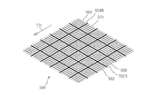
図1は複合型の不織布CWebの一部を示した模式図である。図1では、下側に位置している合成繊維ウエブSWによる合成繊維層(以下、合成繊維層SWと記載する場合もある)と、その上に配置されるパルプ繊維FPによるパルプ繊維層(以下、パルプ繊維層FPと記載する場合もある)との関係が理解し易いように模式的に示している。
本発明に係る不織布CWebは、上記合成繊維層SWと上記パルプ繊維層FPとが一体化してある複合型不織布である。そして、図1では、上側に位置するパルプ繊維層FPの表面には複数の凹凸部が同様の形態で繰り返し形成されている形態を例示している。
Hereinafter, the composite nonwoven fabric according to the embodiment of the present invention will be described with reference to the drawings.
FIG. 1 is a schematic view showing a part of a composite non-woven fabric CWeb. In FIG. 1, a synthetic fiber layer made of a synthetic fiber web SW located on the lower side (hereinafter, may be referred to as a synthetic fiber layer SW) and a pulp fiber layer made of a pulp fiber FP arranged on the synthetic fiber layer (hereinafter, may be referred to as a synthetic fiber layer SW). , Pulp fiber layer FP) is shown schematically for easy understanding.
The non-woven fabric CWeb according to the present invention is a composite non-woven fabric in which the synthetic fiber layer SW and the pulp fiber layer FP are integrated. Then, FIG. 1 illustrates a form in which a plurality of uneven portions are repeatedly formed in the same form on the surface of the pulp fiber layer FP located on the upper side.
上記凹凸部は凹部DEと凸部PRとによるが、パルプ繊維層FPの表面に間隔をもって繰返し凹部(又は凸部)を形成すれば、その間には凸部(又は凹部)が相対的に形成されることになる。
図1では、凹凸部DE、PRを筋状に複数形成した場合の不織布CWebを例示している。この不織布CWebの製造方法については、後述の説明で明らかとする。
また、図示は省略するが、上記凹凸部DE、PRは縦横格子状(網目状、或いはメッシュ状)に複数形成されている形態としてもよい。この不織布CWebの製造方法についても後述の説明で明らかとする。
The uneven portion is composed of the concave portion DE and the convex portion PR, but if the concave portion (or the convex portion) is repeatedly formed on the surface of the pulp fiber layer FP at intervals, the convex portion (or the concave portion) is relatively formed between them. Will be.
FIG. 1 illustrates a non-woven fabric CWeb in which a plurality of uneven portions DE and PR are formed in a streak pattern. The method for producing the non-woven fabric CWeb will be clarified in the description below.
Further, although not shown, a plurality of the uneven portions DE and PR may be formed in a vertical and horizontal lattice shape (mesh shape or mesh shape). The method for producing the non-woven fabric CWeb will also be clarified in the description below.
上述した、本発明に係る不織布CWebは、表面にパルプ繊維が配置され、その表面は凹凸部を有するので表面積が増大することにより吸液性能が向上している。また、凸部ですくった汚れを凹部内に保持するという機能も備えるので拭取り性能も向上する。
よって、吸液性および拭取り性が向上したワイパーに好適な不織布となる。本不織布CWebは、新規な製造法によって得られ、ウエブ原反の形態的な特質として表面のパルプ繊維層に複数の凹凸部を備えている。よって、柔軟性、風合い、嵩高感においても優れた不織布となる。
なお、不織布CWebが吸液性能および拭取り性能を確保するという観点から、上記凹凸部DE、PRについて、前記凹部DEの底部と前記凸部PRの頂部との高低差寸法は例えば200〜800μmとするのが好ましい。これにより確実な拭取り性能を期待できる。
更に、凸部PRの幅は例えば0.5〜3.0mmであり、所定間隔(凹部DEの幅)を例えば0.3〜1.0mmとするのが好ましい。
In the above-mentioned non-woven fabric CWeb according to the present invention, pulp fibers are arranged on the surface thereof, and the surface has uneven portions, so that the surface area is increased and the liquid absorption performance is improved. In addition, since it also has a function of retaining dirt scooped up by the convex portion in the concave portion, the wiping performance is also improved.
Therefore, the non-woven fabric is suitable for wipers with improved liquid absorption and wiping properties. This non-woven fabric CWeb is obtained by a novel manufacturing method, and has a plurality of uneven portions on the surface pulp fiber layer as a morphological characteristic of the web raw fabric. Therefore, the non-woven fabric is excellent in flexibility, texture, and bulkiness.
From the viewpoint of ensuring the liquid absorption performance and the wiping performance of the non-woven fabric CWeb, the height difference between the bottom of the concave portion DE and the top of the convex portion PR of the uneven portions DE and PR is, for example, 200 to 800 μm. It is preferable to do so. As a result, reliable wiping performance can be expected.
Further, the width of the convex portion PR is preferably 0.5 to 3.0 mm, and the predetermined interval (width of the concave portion DE) is preferably 0.3 to 1.0 mm, for example.
以下、上記不織布CWebの製造方法について説明する。製造方法には3つの好適な形態がある。先ず、不織布CWebの製造装置の主要構成について説明をした後に、各製造方法の特徴的構成について個別に説明する。
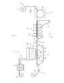
図2に示す複合型不織布の製造装置1は、上流側にパルプエアレイド部としてのエアレイド装置2、合成繊維層供給部としての合成繊維ウエブ供給装置3、そして積層形成部としてのサクション装置4が配設されている。サクション装置4はエアレイド装置2の下側に対向するように配置されている。
搬送方向TDで、これらの装置2、3、4より下流には、上流側から順に、水流交絡部としての水流噴射(ウオータジェット)装置5、脱水・乾燥部として乾燥装置6が配置されている。上記乾燥装置6の下流には連続して製造される複合型の不織布CWebを巻き取るための巻取装置7が更に設けてある。
Hereinafter, a method for producing the above-mentioned non-woven fabric CWeb will be described. There are three suitable forms of the manufacturing method. First, the main configuration of the non-woven fabric CWeb manufacturing apparatus will be described, and then the characteristic configurations of each manufacturing method will be individually described.
The composite non-woven
In the transport direction TD, a water flow injection (water jet)
上記エアレイド装置2は、繊維同士が密集しシート状となっている原料パルプRPをパルプ繊維に解繊(開繊、とも称される)する解繊機21や、図示しない送風機を備えて解繊されたパルプ繊維FPをエアレイドホッパ23へと搬送するダクト22などを有している。エアレイドホッパ23は、その内部において、解繊されたパルプ繊維FPが分散しながら降下し、下面に設定した積層位置24に徐々に積み上がるように設計してある。
上記積層位置24の下側にはサクション装置4が対向配備してある。より詳細には、サクション装置4は装置本体41の上面にサクション部42を有しており、サクション部42が上記パルプ繊維FPに吸引力(負圧)を作用させるべく積層位置24に対して設定してある。
The
A suction device 4 is arranged opposite to the lower side of the stacking
また、サクション装置4の周囲にはウエブ搬送用の搬送ワイヤ43が配設してある。搬送ワイヤ43は、積層位置24においてパルプ繊維FPが載置可能で、これを下流側に搬送するように配置されている。ただし、パルプ繊維FPは直接、搬送ワイヤ43上に載置されない。これについては、後述の説明で明らかとなる。
搬送ワイヤ43はサクション部42の吸引力が、反対側(上側)に及ぶような目開き形態(メッシュ)で形成されている。
Further, a
The
なお、上記原料パルプRPとしては従来の公知のパルプを採用することができる。例えば、木材パルプを採用する場合には、材種としてラジアータパイン、スラッシュパイン、サザンパイン、スプルース、ダグラスファー等のNBKPが好ましく、解繊性や歩留まり等を考慮して適宜に選定すればよい。
さらに、原料パルプRPは、例示のようにロールパルプの形態で供給される場合が多いので、上記解繊装置21としてハンマーミルやディスクミル型等を採用するのが好ましい。ここでの解繊処理は、必要に応じて一段或いは複数段としてもよい。
また、上記原料パルプRPと共に、コットン等の天然繊維や、ポリエステル、ポリプロピレン、ポリエチレン等の合成繊維を追加配合するようにしてもよい。このような配合を採用する際には、別途エアレイドヘッドを追加してウエブ層を重ねるか、開繊したパルプを風送するダクトに別の繊維を混合する風送ラインを追加すればよい。
Conventionally known pulp can be used as the raw material pulp RP. For example, when wood pulp is used, NBKP such as radiata pine, slash pine, southern pine, spruce, and Douglas fir is preferable as the grade, and it may be appropriately selected in consideration of defibration, yield and the like.
Further, since the raw material pulp RP is often supplied in the form of roll pulp as illustrated, it is preferable to adopt a hammer mill, a disc mill type or the like as the
Further, natural fibers such as cotton and synthetic fibers such as polyester, polypropylene and polyethylene may be additionally blended together with the raw material pulp RP. When adopting such a composition, a separate air raid head may be added to superimpose the web layer, or an air blowing line for mixing another fiber may be added to the duct for airing the opened pulp.
上記エアレイド装置2の下側で、サクション装置4よりも上流側に、合成繊維ウエブ供給装置3が配置してある。この合成繊維ウエブ供給装置3には、予め準備された合成繊維ウエブSWがロール状とされてセットされている。合成繊維ウエブ供給装置3から合成繊維ウエブSWが引出され、上述した搬送ワイヤ43に乗って上記積層位置24へと搬送されるようになっている。
上記合成繊維ウエブSWとしては、スパンボンド法により形成された連続フィラメントのウエブを用いるのが好ましい。そして、ここでの合成繊維としては、ナイロン、ビニロン、ポリエステル、アクリル、ポリエチレン、ポリプロピレン、ポリスチレン等から選択するのが好ましい。
The synthetic fiber
As the synthetic fiber web SW, it is preferable to use a web of continuous filaments formed by the spunbond method. The synthetic fiber here is preferably selected from nylon, vinylon, polyester, acrylic, polyethylene, polypropylene, polystyrene and the like.
積層位置24に位置した、合成繊維ウエブSWの上に、前述したパルプ繊維FPが載置される(積み重ねられる)こととなり、合成繊維ウエブSWは搬送ワイヤ43上を下流側へ搬送される。
その際に、積層位置24ではサクション装置4のサクション部42による吸引力が搬送ワイヤ43を通過し、その上の合成繊維ウエブSWおよびパルプ繊維FPに作用する。よって、上記積層位置24を経て下流側に移動した積層状態のウエブは下側の合成繊維層(合成繊維ウエブSW)と、その上に載置されたパルプ繊維層(パルプウエブ)とが積層された状態の予備的積層体PWebとなる。
The pulp fiber FP described above is placed (stacked) on the synthetic fiber web SW located at the stacking
At that time, at the
上記した予備的積層体PWebは、サクション装置4の吸引力によって、吸引圧縮されたことにより積層状態が維持されている。このとき上側のパルプ繊維層はパルプ繊維FPが密にされた状態ではある。しかし、このまま予備的積層体PWebを下流側の水流噴射装置5内に搬送投入すると、水流(ウオータジェット)によってパルプ繊維FPの一部が舞い上がるおそれがある。
そこで、本製造装置1では、予備的積層体PWebを上下から挟んで合成繊維ウエブSW上でのパルプ繊維FPの載置状態を安定化させる為の挟持ローラ28、そして水流噴射装置5の上流側にパルプ繊維FPに飛散防止用に水分を付与するプレウエット装置30が配備してある。プレウエット装置30は、好適には、予備的積層体PWebの上方からウオータミストを吹き付ける噴霧ノズル31と予備的積層体PWebの下側(すなわち、合成繊維ウエブSWの下面)から吸引力を印加するサクション装置32とを含んで構成されている。
The preliminary laminated body PWeb described above is maintained in a laminated state by being suction-compressed by the suction force of the suction device 4. At this time, the pulp fiber layer on the upper side is in a state where the pulp fiber FP is densely packed. However, if the preliminary laminated body PWeb is conveyed and thrown into the water
Therefore, in the
上記挟持ローラ28とプレウエット装置30とは、水流噴射装置5内における水流交絡処理の円滑な実行のための前処理部と理解することができる。図2に示した前処理部は、好適構成例であり、挟持ローラ28を省略した構成とすることも可能である。
The sandwiching
水流噴射装置5は、前処理部28、30の処理を受けた予備的積層体PWebに高圧のウオータジェットを吹き付けることによりパルプ繊維同士の交絡を促進する。これにより上側に位置するパルプ繊維層と下側に位置する合成繊維層との一体化が促進される。
図2で例示的に示している水流噴射装置5は、搬送方向TDに沿って多段(図2では例示しているのは4段)に水流噴射ノズル51が配置されている。第1段目の水流噴射ノズルを低圧で吹き付ける事により、上述したプレウエット装置30の代用としてもよい。
図2では、搬送方向TDに対して直角な方向(装置1の幅方向)におけるノズルの様子は図示していないが、幅方向においても複数の水流噴射ノズルが配置してある。
The water
In the water
In FIG. 2, the state of the nozzles in the direction perpendicular to the transport direction TD (the width direction of the device 1) is not shown, but a plurality of water flow injection nozzles are also arranged in the width direction.
上記水流交絡処理をする際の水圧は、パルプ繊維層(ウエブ)と合成繊維層(ウエブ)の坪量を勘案して設定するのが望ましい。例えば、1〜30MPaの範囲において選択するのが好ましい。 It is desirable that the water pressure at the time of performing the water flow confounding treatment is set in consideration of the basis weight of the pulp fiber layer (web) and the synthetic fiber layer (web). For example, it is preferable to select in the range of 1 to 30 MPa.
そして、上記水流噴射ノズル51と対向するように、サクション装置52が配設してある。水流噴射ノズル51から出る高圧のウオータジェットを上側に位置しているパルプウエブに吹き付けつつ、下側に位置している合成繊維層の下側にサクション装置52の吸引力を作用させる。水流噴射ノズル51とサクション装置52との協働作用によって、パルプウエブのパルプ繊維が下側の合成繊維ウエブの繊維に入り込んだ状態や、合成繊維ウエブを貫通して反対側にまで至った状態などが形成されると推定される。その作用により2つの層の一体化が促進される。
The
水流噴射装置5にも、搬送ワイヤ55が配設してある。搬送ワイヤ55は前処理部28、30の下流で予備的積層体PWebを受けて、水流噴射装置5内へと搬送する。搬送ワイヤ55は水流噴射装置5の水流噴射ノズル51とサクション装置52との間を、上流側から下流に向かって通過するように配設されている。
よって、搬送ワイヤ55上を搬送される予備的積層体PWebは、搬送方向TDで下流に向かう程に、より多くの水流交絡処理を受けることになり、水流噴射装置5を出るときには上側のパルプ繊維層と下側の合成繊維ウエブとの十分な交絡処理が実現される。
水流噴射装置5を出た直後にあっては、ウエブはウエット状態であり、乾燥前にあってはパルプ繊維同士の結合は十分に確立されてはいない。
The
Therefore, the preliminary laminated body PWeb transported on the
Immediately after leaving the water
そこで、水流噴射装置5の下流側にウエット状態のウエブから水を除くための乾燥装置6が配備してある。ここで例示する乾燥装置6は好適にはエアスルードライヤである。回転可能なドライヤ本体61は筒状体であり、その周表面には多数の貫通孔が設けてあり、図示しない熱源で加熱された熱風がドライヤ本体61の中心部側から外周に向かって放射状に吹き出す構成である。よって、ウエット状態のウエブが乾燥装置6から出るときには十分に乾燥されて繊維同士の結合も完了し、製品として完成した複合型の不織布CWebとなる。このように連続的に製造される複合型の不織布CWebは巻取装置7のローラ71に巻き取られて一連の工程が完了する。
Therefore, a
以上、本発明に係る複合型の不織布を製造するための、製造装置の基本構成について説明した。以下では、パルプ繊維層に凹凸部を形成するための具体的な構成について説明する。
前述したように、不織布CWebを製造するための製造装置1は、水流交絡処理を行う水流噴射装置5を含んでおり、水流噴射ノズル51と、これに対向するように配置したサクション装置52との間に、予備的積層体PWebを投入して搬送することにより交絡処理が実現される。
本発明の製造方法は、水流噴射装置5から出たウエット状態のウエブ(原反)がその特質として、表面のパルプ繊維層に凹凸部が形成されている不織布CWebを、簡易な構成で製造することを可能としている発明である。以下、3つの発明を順に説明する。
The basic configuration of the manufacturing apparatus for manufacturing the composite nonwoven fabric according to the present invention has been described above. Hereinafter, a specific configuration for forming the uneven portion on the pulp fiber layer will be described.
As described above, the
The manufacturing method of the present invention is characterized by a wet web (original fabric) emitted from the water
図3は、パルプ繊維層FPに凹凸部DE、PRが形成されている複合型不織布を製造するための、第1の方法を説明するために示した模式図である。図3は水流噴射装置5の一部構成と、これに関連している周部を拡大して示している。具体的には、搬送方向TDに直角方向に配置した複数の水流噴射ノズル510、搬送ワイヤ55、そして搬送ワイヤ55の下側に配置したサクション装置52および搬送ワイヤ55上に載置されている前記予備的積層体PWebの様子を、図3は模式的に示している。
図3で示す構成では、水流噴射ノズル510はそのノズル直径が例えば0.15〜0.25mmに設定されている。一般的な従来型の水流噴射ノズルは、前記水流噴射ノズル510よりは小径で例えばノズル直径が0.05〜0.15mmである。噴射水量はノズル径の2乗に比例するので、上記水流噴射ノズル510は従来よりも多くの水を吐出することができる。
後述するように、従来よりも大きい直径(大径)の水流噴射ノズル510と従来型の水流噴射ノズルとを併用して水流交絡を実施するときには、水流噴射ノズル510は従来型の水流噴射ノズルと比較して1.2〜2.0倍の直径に設定しておくのが好ましい。これは、水流噴射ノズル510の直径を基準に見たときには、小径となる従来型の水流噴射ノズルの直径は0.5〜0.83倍のものを採用するのが好ましいことになる。
そして、上記水流噴射ノズルの水圧は上述したように1〜30MPaとするのが望ましく、直径が相対的に大きな水流噴射ノズル510を採用したときには、従来よりも配置のピッチを広げて、幅当りの配置本数を減らして設定すればよい。
FIG. 3 is a schematic view shown for explaining a first method for producing a composite nonwoven fabric in which uneven portions DE and PR are formed on the pulp fiber layer FP. FIG. 3 shows an enlarged view of a partial configuration of the water
In the configuration shown in FIG. 3, the water
As will be described later, when water flow confounding is performed by using a water
The water pressure of the water flow injection nozzle is preferably 1 to 30 MPa as described above, and when the water
一般的に、合成繊維SWの下側にサクション装置52が配置されているので余剰の水を除去しながら、水流噴射ノズルからの水流を予備的積層体PWebに貫通することで、この水流に合わせて繊維同士を交絡させることができる。その際に、本発明では水流噴射ノズル510を従来よりも直径が大きい(太い)ノズルを採用しているので、水流の中心部のパルプ繊維層FPを周辺に弾く(はじく)或いは排除する状態が生じる。より詳細には、水流噴射ノズル510の下側にはサクション装置52が配置されているが、従来よりも太い水流の場合、部分的に下からの吸引力で対応できない。これにより、予備的積層体PWebの上側にある相対的に剛性の低いパルプ繊維層FPには、水流噴射ノズル510の対応する位置に凹状が形成される。そして、予備的積層体PWebは搬送ワイヤ55上を搬送方向TDへ搬送されているので、図3で示すように下流に向かって複数の筋状の凹凸部(凹部DE、凸部PR)が形成されることになる。
Generally, since the
図3による水流噴射ノズル510は、従来型の水流噴射ノズルよりも大型であり、従来型の水流噴射ノズルよりも減数され、間隔を広く取って配置されることになる。この間隔が凹部DEの間隔に対応し、その間に凸部PRが形成されることになる。なお、図3は発明を理解し易いように、パルプ繊維層FPの様子を模式的に示している。
The water
先の図2で示しているように水流噴射装置5における、水流噴射ノズル51とサクション装置52とは搬送方向TDに沿って多段(図2での例示は4段)に形成してある。
図3による発明を実施する場合にも、水流噴射ノズル510を図2で示すように多段に配置して、予備的積層体PWebの同じ位置に向けて水流噴射ノズル510によるウオータジェットを繰り返し吹き付けることで凹部DEを確実に形成できる。凹部DEの形成をより確実とするため水流噴射ノズル510の段数を必要により任意に設定してよいことは勿論である。この場合、ノズルの位置が微調整できる設備であることが好ましい。
As shown in FIG. 2, the water
Also in the case of carrying out the invention according to FIG. 3, the water
ところで、図2で示した形態例のように水流噴射ノズルを4段とした場合、次のように処理するのが好ましい。
最初の1段目の水流噴射ノズル51については、従来型のもの(図3の水流噴射ノズル510より小径のもの)を用いて、パルプ繊維層FPの全面に向けてウオータジェットを吹付ける水流交絡処理(第1の水流交絡)を行い、全体のパルプ繊維の交絡を行う。
次に、第2、3段目の水流噴射ノズル51については、図3で説明したノズル直径を0.15〜0.25mmとした大きな直径の上記水流噴射ノズル510を用いて、凹凸部を形成するための水流交絡処理(第2の水流交絡処理)を実行する。
そして、最後の第4段目の水流噴射ノズル51については、最初の第1段目と同様に、従来型の小径の水流噴射ノズルを用いて、パルプ繊維層FPの全面に向けてウオータジェットを吹き付ける水流交絡処理を実行するようにするのが、より好ましい。
By the way, when the water flow injection nozzle has four stages as in the embodiment shown in FIG. 2, it is preferable to perform the treatment as follows.
As for the first-stage water
Next, with respect to the second and third stages of the water
Then, with respect to the final fourth-stage water
上記のように従来型の水流交絡処理である第1の水流交絡処理を最初と最後とに実行すると、初期の未固定の繊維が飛散することを防止できるため、より明瞭なパターンを形成することができる。そして、パルプ繊維層FPと合成繊維SWとの交絡を最後に全体的に行うことができるので、より強固な複合型不織布CWebが得られる。
なお、上記第2の水流交絡処理(ノズル径の大きい水流交絡処理)を先に行うと大径のノズルにより未交絡パルプ繊維が飛散する可能性があり、これにより外観が悪化して凹凸パターンを乱してしまうことが懸念される。また、上記第2の水流交絡処理を最後とするのも好ましくない。凸部に移動したパルプ繊維の交絡が不十分な状態で残り、ウエブ全体として交絡が完了していない状態となるためである。
When the first water flow entanglement treatment, which is the conventional water flow entanglement treatment, is performed at the beginning and the end as described above, it is possible to prevent the initial unfixed fibers from scattering, so that a clearer pattern can be formed. Can be done. Then, since the pulp fiber layer FP and the synthetic fiber SW can be entangled as a whole at the end, a stronger composite non-woven fabric CWeb can be obtained.
If the second water flow entanglement treatment (water flow entanglement treatment having a large nozzle diameter) is performed first, unentangled pulp fibers may be scattered by the large diameter nozzle, which deteriorates the appearance and causes an uneven pattern. There is concern that it will be disturbed. It is also not preferable to finish the second water flow entanglement treatment. This is because the entanglement of the pulp fibers that have moved to the convex portion remains in an insufficient state, and the entanglement of the entire web is not completed.
図4は、第2の方法を説明するために示した図である。図4も水流噴射装置5の一部構成とこれに関連した周部を拡大して示している。搬送方向TDに直角方向に配置した複数の水流噴射ノズル51、搬送ワイヤ55、そして搬送ワイヤ55の下側に配置したサクション装置52および搬送ワイヤ55上に載置されている前記予備的積層体PWebの様子を模式的に示している点は、図4も図3と同様である。
FIG. 4 is a diagram shown for explaining the second method. FIG. 4 also shows an enlarged view of a partial configuration of the water
ここでは、第1の方法と異なる点を中心に説明する。図4で示したサクション装置52には、吸引力を作用させるために設けてある開口部520に不透水部521が設けてある。この不透水部521は、吸引力が作用しないように配置された邪魔板として機能する。不透水部521は搬送方向TDと直角な方向にて間隔もって複数配置されている。不透水部521が存在する部分は、予備的積層体PWebに吸引力が作用しない。その一方、不透水部521が存在しない部分には吸引力が作用する。これにより吸引力が作用している不透水部521の両側にパルプ繊維が逃げるような(回り込むような)状態が形成される。その結果、不透水部521に対応する位置にあるパルプ繊維層は凹部DEとなり、不透水部521の間で吸引力が作用する位置にあるパルプ繊維層は凸部PRとなる。
上記凹部DEを形成するのに好ましい不透水部521は例えば幅1mm以上であり、間隔3〜5mmとして設定するのが好ましい。
なお、上記サクション装置52による吸引力(負圧)は例えば0.01〜0.05(Mpa)とするのが望ましい。ここで、0.01MPaは、100mbar或いは75mmHgに等しい。
Here, the points different from the first method will be mainly described. In the
The
The suction force (negative pressure) of the
図4の場合も、図3の場合と同様に、同じ位置に不透水部521が形成してあるサクション装置52を搬送方向TDにおいて多段に配置して、確実に凹凸部を形成するようにするのが好ましい。
そして、最初と最後とに位置するサクション装置52については、不透水部521を設けず、予備的積層体PWebの全体に吸引力を作用させてパルプ繊維層FPと合成繊維SWとの交絡を全体的に実現するようにするのが好ましい。この点は、図3で示した第1の製造法で最後にパルプ繊維層FP上の全面にウオータジェットを吹き付けているのと同じ趣旨である。
なお、図4で例示している水流噴射ノズル51は従来型であり、そのノズル直径が0.05〜0.15mmで、パルプ繊維層FP上の全面にウオータジェットを吹き付けるものでよい。
以上のように、図4に示したサクション装置52を用いた製造方法によっても、パルプ繊維層の表面に凹凸部が形成されている複合型不織布を製造できる。
In the case of FIG. 4, as in the case of FIG. 3, the
The
The water
As described above, the composite non-woven fabric in which the uneven portion is formed on the surface of the pulp fiber layer can also be manufactured by the manufacturing method using the
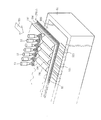
更に、第3の製造法について説明する。従来において、搬送ワイヤは複数の縦糸と横糸とを網目状(メッシュ状)に配置し、同じ太さの糸により構成するのが一般的であった。第3の製造法は、一般的な概念の搬送ワイヤとは異なる新規の搬送ワイヤを用いた水流交絡処理を行って複合型不織布を製造する。
図5は、第3の製造法で採用できる、一例である搬送ワイヤ550の一部を拡大した図を示している。この搬送ワイヤ550は複数の縦糸551の内で所定本数毎(例示では5本毎)に直径が他の縦糸よりも太い縦糸551Bが配置してある。なお、縦糸551は搬送方向TDと平行である。
Further, a third manufacturing method will be described. Conventionally, in a transport wire, a plurality of warp threads and weft threads are generally arranged in a mesh shape and composed of threads having the same thickness. In the third manufacturing method, a composite non-woven fabric is manufactured by performing a water flow entanglement treatment using a new transport wire different from the transport wire of the general concept.
FIG. 5 shows an enlarged view of a part of the
同様に、この搬送ワイヤ550は複数の横糸552の内で所定本数毎(例示では5本毎)に直径が他の横糸よりも太い横糸552Bが配置してある。
ここで、搬送ワイヤ550の縦糸551、横糸552は一般的な直径0.2〜0.6mmであるが、上記太い縦糸551B、太い縦糸551Bは例えば直径1mm以上とするのが好ましい。或いは、他の糸の直径と比較して太い糸の直径を例えば3〜5倍に設定するのが好ましい。これにより、パルプ繊維層の表面に凹凸部を確実に形成することができる。この場合、縦糸と横糸のそれぞれの開口率は10%以上とすることが好ましく、20〜30%とすることがより好ましい。ここでの開口率(%)は1cm内に存在する糸の本数と、その糸の直径に基づいて定義される。具体的には、開口率(%)は式[(1−糸本数×糸径)/1]×100(%)により算出できる。
Similarly, in the
Here, the
上記のような搬送ワイヤ550を用いた水流噴射装置5により水流交絡処理を行うと、太い糸が存在する位置(領域)に対応する位置にあるパルプ繊維層には凹部が形成される。太い糸の上に存在するパルプ繊維層への吸引力の作用が制限されるので、吸引力が作用している両側へパルプ繊維が逃げるような(回り込むような)状態が形成される。その結果として、太い糸の両側でパルプ繊維層に凸部が形成され、太い糸が存在する位置に対応して凹部が形成されることになる。
以上で説明したように、水流噴射装置5に用いる搬送ワイヤを工夫することによっても、パルプ繊維層に凹凸部が形成されている、複合型不織布を製造することができる。
When the water flow entanglement treatment is performed by the water
As described above, by devising the transport wire used for the water
図5で示した搬送ワイヤ550は、縦および横の両方に太い糸を配置してある場合を例示しており、この搬送ワイヤ550を用いた場合には縦横格子状となった凹凸部がパルプ繊維層の表面に形成される。
搬送ワイヤ550で縦糸側にのみ太い糸を配置した場合には、前述した第1、第2の製造方法と同様に搬送方向TDに沿った筋状の凹凸部をパルプ繊維層の表面に形成できる。
上記とは逆に、搬送ワイヤ550で横糸側にのみ太い糸を配置した場合には、前述した第1、第2の製造方法では作製できない、搬送方向TDと直角な方向に沿った(直角な方向に平行である)筋状の凹凸部をパルプ繊維層の表面に形成することもできる。
なお、図5の糸の配置は単なる例示である。搬送ワイヤ550を編機で作製する場合に、横糸を所定本数毎に変更すると製造工程が極めて煩瑣になる。よって、全ての横糸を前述した太糸としてもよい。この場合、太糸は所定間隔をもって配置されるので、その太糸の間に相当する位置に対応してパルプ繊維層の表面に凸部が形成されることになる。
The
When a thick yarn is arranged only on the warp side of the
Contrary to the above, when a thick thread is arranged only on the weft side with the
The arrangement of the threads in FIG. 5 is merely an example. When the
上述した第1〜第3の製造法によると、基本とした不織布製造装置に簡易な変更を加えるだけで、パルプ繊維層の表面に凹凸部が形成された複合型不織布を製造できる。
なお、第1〜第3の製造法の説明では、凹凸部が同じパターンで繰り返される場合を図示しているが、これは単なる例示である。不織布の製品要求により、凹部と凸部とを同じ幅としたり、互いに異なる幅とする場合、また凹部および凸部とを不規則に変更してある点をデザインとした不織布を製造したいという場合もある。このような場合には、前述した水流噴射ノズル(510)、不透水部(521)および搬送ワイヤ(550)における太い糸(551B、552B)の位置や配列の設定を適宜に変更して対応すればよい。
さらに、上記では、第1、第2、第3の製造方法を個別に説明したが、必要によりこれらを適宜に組合せてパルプ繊維層の表面に凹凸部のある複合型不織布を製造してもよい。方法を組合せて製造することで、より顕著な凹凸部をパルプ繊維層に形成できる。
According to the first to third manufacturing methods described above, a composite non-woven fabric in which uneven portions are formed on the surface of the pulp fiber layer can be manufactured by simply making simple changes to the basic non-woven fabric manufacturing apparatus.
In the description of the first to third manufacturing methods, the case where the uneven portions are repeated in the same pattern is illustrated, but this is merely an example. Depending on the product requirements of the non-woven fabric, there are cases where the concave and convex parts have the same width or different widths from each other, or when it is desired to manufacture a non-woven fabric whose design is that the concave and convex parts are irregularly changed. is there. In such a case, the positions and arrangement settings of the thick threads (551B and 552B) in the water flow injection nozzle (510), the impermeable portion (521) and the transfer wire (550) described above should be appropriately changed. Just do it.
Further, in the above, the first, second, and third manufacturing methods have been described individually, but if necessary, these may be appropriately combined to manufacture a composite non-woven fabric having uneven portions on the surface of the pulp fiber layer. .. By combining the methods, a more prominent uneven portion can be formed in the pulp fiber layer.
以上で実施形態の説明を終えるが、本発明は上記実施形態に限定されるものではなく、その要旨を逸脱しない範囲で種々変更して実施することができることは言うまでもない。 Although the description of the embodiment is completed above, it is needless to say that the present invention is not limited to the above embodiment and can be variously modified and implemented without departing from the gist thereof.
1 複合型不織布の製造装置
2 エアレイド装置
3 合成繊維ウエブ供給装置
4 サクション装置
5 水流噴射装置
6 乾燥装置
7 巻取装置
21 解繊機
22 ダクト
23 エアレイドホッパ
24 積層位置
28 挟持ローラ
30 プレウエット装置
31 噴霧ノズル
32 サクション装置
41 サクション装置本体
42 サクション部
43 搬送ワイヤ
51 水流噴射ノズル
52 サクション装置
55 搬送ワイヤ
510 水流噴射ノズル
520 開口部
521 不透水部
550 搬送ワイヤ
551 縦糸
551B 太い縦糸
552 横糸
552B 太い横糸
FP パルプ繊維(パルプ繊維層)
PWeb 予備的積層体
CWeb 積層体(複合型不織布)
SW 合成繊維ウエブ(合成繊維層)
DE パルプ繊維層の凹部
PR パルプ繊維層の凸部
1 Composite non-woven
PWeb preliminary laminate CWeb laminate (composite type non-woven fabric)
SW Synthetic Fiber Web (Synthetic Fiber Layer)
DE Concave part of pulp fiber layer PR Convex part of pulp fiber layer
Claims (3)
前記合成繊維層と、前記合成繊維層の上に載置される前記パルプ繊維とによって形成される予備的積層体に向けてウオータジェットを吹き付けて水流交絡処理を施し、前記パルプ繊維層と前記合成繊維層との一体化を促進する水流交絡工程を少なくとも含み、
前記水流交絡工程では、前記予備的積層体を搬送ワイヤ上に載置して搬送し、搬送方向と直角方向に配置した複数の水流噴射ノズルから前記ウオータジェットを前記パルプ繊維層に向けて吹き付けると共に前記搬送ワイヤの下側に配置したサクション装置で吸引をして、前記水流噴射ノズルに対応した位置を凹部として、前記パルプ繊維層の表面に複数の筋状の凹凸部を形成するものにおいて、
前記複数の水流噴射ノズルはノズル直径が0.15〜0.25mmであり、該複数の水流噴射ノズルは搬送方向に沿って複数段に配置してあり、
前記複数段の水流噴射ノズルによる第2の水流交絡処理の前後で、前記複数段の水流噴射ノズルよりも小さい直径の水流噴射ノズルを用いて、前記パルプ繊維層の全面に向けてウオータジェットを吹付ける第1の水流交絡処理を行う、ことを特徴とする複合型不織布の製造方法。 It is a method of producing a composite non-woven fabric in which a pulp fiber layer is laminated on a synthetic fiber layer and integrated.
A water jet is sprayed onto the preliminary laminate formed by the synthetic fiber layer and the pulp fiber placed on the synthetic fiber layer to perform a water flow entanglement treatment, and the pulp fiber layer and the synthesis are performed. Including at least a water flow entanglement step that promotes integration with the fiber layer,
In the water flow entanglement step, the preliminary laminate is placed on a transfer wire and conveyed, and the water jet is sprayed toward the pulp fiber layer from a plurality of water flow injection nozzles arranged in a direction perpendicular to the transfer direction. In a device in which suction is performed by a suction device arranged under the transport wire and a plurality of streaky uneven portions are formed on the surface of the pulp fiber layer with a position corresponding to the water flow injection nozzle as a recess.
The plurality of water flow injection nozzles have a nozzle diameter of 0.15 to 0.25 mm, and the plurality of water flow injection nozzles are arranged in a plurality of stages along the transport direction.
Before and after the second water flow confounding treatment by the multi-stage water flow injection nozzle, a water jet is blown toward the entire surface of the pulp fiber layer using a water flow injection nozzle having a diameter smaller than that of the multi-stage water flow injection nozzle. A method for producing a composite non-woven fabric, which comprises performing a first water flow entanglement treatment .
前記合成繊維層と、前記合成繊維層の上に載置される前記パルプ繊維とによって形成される予備的積層体に向けてウオータジェットを吹き付けて水流交絡処理を施し、前記パルプ繊維層と前記合成繊維層との一体化を促進する水流交絡工程を少なくとも含み、
前記水流交絡工程では、前記予備的積層体を搬送ワイヤ上に載置して搬送し、搬送方向と直角方向に配置した複数の水流噴射ノズルから前記ウオータジェットを前記パルプ繊維層に向けて吹き付けると共に、前記搬送ワイヤの下側に配置したサクション装置で吸引し、
前記搬送ワイヤは複数の縦糸と横糸とによって形成され、前記縦糸と前記横糸との少なくとも一方について、他の糸よりも太い直径の太糸が間隔をもって複数配置された形態を有しており、前記太糸の位置に対応して前記パルプ繊維層の表面に凹部を複数形成することにより、複数の筋状の凹凸部または複数の縦横格子状の凹凸部を形成する、ことを特徴とする複合型不織布の製造方法。 It is a method of producing a composite non-woven fabric in which a pulp fiber layer is laminated on a synthetic fiber layer and integrated.
A water jet is sprayed onto the preliminary laminate formed by the synthetic fiber layer and the pulp fiber placed on the synthetic fiber layer to perform a water flow entanglement treatment, and the pulp fiber layer and the synthesis are performed. Including at least a water flow entanglement step that promotes integration with the fiber layer,
In the water flow entanglement step, the preliminary laminate is placed on a transfer wire and conveyed, and the water jet is sprayed toward the pulp fiber layer from a plurality of water flow injection nozzles arranged in a direction perpendicular to the transfer direction. , Suction with a suction device arranged under the transfer wire,
The transport wire is formed of a plurality of warp threads and weft threads, and has a form in which a plurality of thick threads having a diameter larger than that of the other threads are arranged at intervals for at least one of the warp threads and the weft threads. A composite type characterized in that a plurality of streaky uneven portions or a plurality of vertical and horizontal lattice-shaped uneven portions are formed by forming a plurality of recesses on the surface of the pulp fiber layer corresponding to the position of the thick yarn. Non-woven fabric manufacturing method .
Priority Applications (1)
| Application Number | Priority Date | Filing Date | Title |
|---|---|---|---|
| JP2016170242A JP6758131B2 (en) | 2016-08-31 | 2016-08-31 | Composite non-woven fabric and its manufacturing method |
Applications Claiming Priority (1)
| Application Number | Priority Date | Filing Date | Title |
|---|---|---|---|
| JP2016170242A JP6758131B2 (en) | 2016-08-31 | 2016-08-31 | Composite non-woven fabric and its manufacturing method |
Publications (2)
| Publication Number | Publication Date |
|---|---|
| JP2018035468A JP2018035468A (en) | 2018-03-08 |
| JP6758131B2 true JP6758131B2 (en) | 2020-09-23 |
Family
ID=61565451
Family Applications (1)
| Application Number | Title | Priority Date | Filing Date |
|---|---|---|---|
| JP2016170242A Active JP6758131B2 (en) | 2016-08-31 | 2016-08-31 | Composite non-woven fabric and its manufacturing method |
Country Status (1)
| Country | Link |
|---|---|
| JP (1) | JP6758131B2 (en) |
Families Citing this family (1)
| Publication number | Priority date | Publication date | Assignee | Title |
|---|---|---|---|---|
| JP7121557B2 (en) * | 2018-06-21 | 2022-08-18 | 日本製紙クレシア株式会社 | Manufacturing method of non-woven wiper |
Family Cites Families (3)
| Publication number | Priority date | Publication date | Assignee | Title |
|---|---|---|---|---|
| JP2986689B2 (en) * | 1994-08-29 | 1999-12-06 | ユニ・チャーム株式会社 | Manufacturing method of nonwoven wiper |
| JP2002275752A (en) * | 2001-03-16 | 2002-09-25 | Oji Paper Co Ltd | Composite nonwoven fabric and method for producing the same |
| JP2008208492A (en) * | 2007-02-27 | 2008-09-11 | Kochi Prefecture | Moisturizing nonwoven fabric and method for producing the same |
-
2016
- 2016-08-31 JP JP2016170242A patent/JP6758131B2/en active Active
Also Published As
| Publication number | Publication date |
|---|---|
| JP2018035468A (en) | 2018-03-08 |
Similar Documents
| Publication | Publication Date | Title |
|---|---|---|
| JP6758116B2 (en) | Composite non-woven fabric manufacturing equipment and its manufacturing method | |
| CN100372985C (en) | Method and apparatus for producing an airlaid and hydroentangled fiber web without a base web | |
| US7331089B2 (en) | Method and apparatus for dry forming of a fabric | |
| JP7307632B2 (en) | Manufacturing method of composite nonwoven fabric | |
| JP7509539B2 (en) | Composite nonwoven fabric and its manufacturing method | |
| CN101124358A (en) | Manufacture of multilayer fabrics | |
| JP7509538B2 (en) | Composite nonwoven fabric and its manufacturing method | |
| JP2019039116A (en) | Non-woven wiper and method for producing the same | |
| JP2022003173A (en) | Composite non-woven fabric and its manufacturing method | |
| JP6902341B2 (en) | Manufacturing method of composite non-woven fabric and its manufacturing equipment | |
| JP7128682B2 (en) | Non-woven wiper and manufacturing method thereof | |
| JP7324014B2 (en) | Composite type nonwoven fabric and its manufacturing method | |
| JP7324011B2 (en) | Composite type nonwoven fabric and its manufacturing method | |
| JP6758131B2 (en) | Composite non-woven fabric and its manufacturing method | |
| JP7257767B2 (en) | Manufacturing method of composite nonwoven fabric wiper | |
| JP7481083B2 (en) | Manufacturing method of nonwoven wiper | |
| JP2019119963A (en) | Nonwoven fabric wiper, method and apparatus for producing the same | |
| JP7237571B2 (en) | Composite type nonwoven fabric and its manufacturing method | |
| JP7216528B2 (en) | Manufacturing method of composite nonwoven fabric wiper | |
| JP7652591B2 (en) | Composite nonwoven fabric manufacturing equipment | |
| JP7088747B2 (en) | Non-woven fabric manufacturing equipment | |
| JP7497016B2 (en) | Composite nonwoven fabric, its manufacturing method, and composite nonwoven fabric manufacturing device | |
| JP6910122B2 (en) | Composite non-woven fabric and its manufacturing equipment | |
| JP7121557B2 (en) | Manufacturing method of non-woven wiper | |
| JP7529398B2 (en) | Composite nonwoven fabric and its manufacturing method |
Legal Events
| Date | Code | Title | Description |
|---|---|---|---|
| A621 | Written request for application examination |
Free format text: JAPANESE INTERMEDIATE CODE: A621 Effective date: 20190524 |
|
| A977 | Report on retrieval |
Free format text: JAPANESE INTERMEDIATE CODE: A971007 Effective date: 20200422 |
|
| A131 | Notification of reasons for refusal |
Free format text: JAPANESE INTERMEDIATE CODE: A131 Effective date: 20200527 |
|
| A521 | Written amendment |
Free format text: JAPANESE INTERMEDIATE CODE: A523 Effective date: 20200722 |
|
| TRDD | Decision of grant or rejection written | ||
| A01 | Written decision to grant a patent or to grant a registration (utility model) |
Free format text: JAPANESE INTERMEDIATE CODE: A01 Effective date: 20200805 |
|
| A61 | First payment of annual fees (during grant procedure) |
Free format text: JAPANESE INTERMEDIATE CODE: A61 Effective date: 20200901 |
|
| R150 | Certificate of patent or registration of utility model |
Ref document number: 6758131 Country of ref document: JP Free format text: JAPANESE INTERMEDIATE CODE: R150 |