JP6753054B2 - Liquid storage container and protective member - Google Patents
Liquid storage container and protective member Download PDFInfo
- Publication number
- JP6753054B2 JP6753054B2 JP2015231542A JP2015231542A JP6753054B2 JP 6753054 B2 JP6753054 B2 JP 6753054B2 JP 2015231542 A JP2015231542 A JP 2015231542A JP 2015231542 A JP2015231542 A JP 2015231542A JP 6753054 B2 JP6753054 B2 JP 6753054B2
- Authority
- JP
- Japan
- Prior art keywords
- wall portion
- liquid
- engaged
- engaging
- wall
- Prior art date
- Legal status (The legal status is an assumption and is not a legal conclusion. Google has not performed a legal analysis and makes no representation as to the accuracy of the status listed.)
- Active
Links
Images


Classifications
-
- B—PERFORMING OPERATIONS; TRANSPORTING
- B41—PRINTING; LINING MACHINES; TYPEWRITERS; STAMPS
- B41J—TYPEWRITERS; SELECTIVE PRINTING MECHANISMS, i.e. MECHANISMS PRINTING OTHERWISE THAN FROM A FORME; CORRECTION OF TYPOGRAPHICAL ERRORS
- B41J2/00—Typewriters or selective printing mechanisms characterised by the printing or marking process for which they are designed
- B41J2/005—Typewriters or selective printing mechanisms characterised by the printing or marking process for which they are designed characterised by bringing liquid or particles selectively into contact with a printing material
- B41J2/01—Ink jet
- B41J2/17—Ink jet characterised by ink handling
- B41J2/175—Ink supply systems ; Circuit parts therefor
- B41J2/17503—Ink cartridges
- B41J2/17536—Protection of cartridges or parts thereof, e.g. tape
-
- B—PERFORMING OPERATIONS; TRANSPORTING
- B41—PRINTING; LINING MACHINES; TYPEWRITERS; STAMPS
- B41J—TYPEWRITERS; SELECTIVE PRINTING MECHANISMS, i.e. MECHANISMS PRINTING OTHERWISE THAN FROM A FORME; CORRECTION OF TYPOGRAPHICAL ERRORS
- B41J2/00—Typewriters or selective printing mechanisms characterised by the printing or marking process for which they are designed
- B41J2/005—Typewriters or selective printing mechanisms characterised by the printing or marking process for which they are designed characterised by bringing liquid or particles selectively into contact with a printing material
- B41J2/01—Ink jet
- B41J2/17—Ink jet characterised by ink handling
- B41J2/175—Ink supply systems ; Circuit parts therefor
- B41J2/17503—Ink cartridges
- B41J2/17506—Refilling of the cartridge
- B41J2/17509—Whilst mounted in the printer
-
- B—PERFORMING OPERATIONS; TRANSPORTING
- B41—PRINTING; LINING MACHINES; TYPEWRITERS; STAMPS
- B41J—TYPEWRITERS; SELECTIVE PRINTING MECHANISMS, i.e. MECHANISMS PRINTING OTHERWISE THAN FROM A FORME; CORRECTION OF TYPOGRAPHICAL ERRORS
- B41J2/00—Typewriters or selective printing mechanisms characterised by the printing or marking process for which they are designed
- B41J2/005—Typewriters or selective printing mechanisms characterised by the printing or marking process for which they are designed characterised by bringing liquid or particles selectively into contact with a printing material
- B41J2/01—Ink jet
- B41J2/17—Ink jet characterised by ink handling
- B41J2/175—Ink supply systems ; Circuit parts therefor
- B41J2/17503—Ink cartridges
- B41J2/1752—Mounting within the printer
-
- B—PERFORMING OPERATIONS; TRANSPORTING
- B41—PRINTING; LINING MACHINES; TYPEWRITERS; STAMPS
- B41J—TYPEWRITERS; SELECTIVE PRINTING MECHANISMS, i.e. MECHANISMS PRINTING OTHERWISE THAN FROM A FORME; CORRECTION OF TYPOGRAPHICAL ERRORS
- B41J2/00—Typewriters or selective printing mechanisms characterised by the printing or marking process for which they are designed
- B41J2/005—Typewriters or selective printing mechanisms characterised by the printing or marking process for which they are designed characterised by bringing liquid or particles selectively into contact with a printing material
- B41J2/01—Ink jet
- B41J2/17—Ink jet characterised by ink handling
- B41J2/175—Ink supply systems ; Circuit parts therefor
- B41J2/17503—Ink cartridges
- B41J2/17526—Electrical contacts to the cartridge
- B41J2/1753—Details of contacts on the cartridge, e.g. protection of contacts
-
- B—PERFORMING OPERATIONS; TRANSPORTING
- B41—PRINTING; LINING MACHINES; TYPEWRITERS; STAMPS
- B41J—TYPEWRITERS; SELECTIVE PRINTING MECHANISMS, i.e. MECHANISMS PRINTING OTHERWISE THAN FROM A FORME; CORRECTION OF TYPOGRAPHICAL ERRORS
- B41J2/00—Typewriters or selective printing mechanisms characterised by the printing or marking process for which they are designed
- B41J2/005—Typewriters or selective printing mechanisms characterised by the printing or marking process for which they are designed characterised by bringing liquid or particles selectively into contact with a printing material
- B41J2/01—Ink jet
- B41J2/17—Ink jet characterised by ink handling
- B41J2/175—Ink supply systems ; Circuit parts therefor
- B41J2/17503—Ink cartridges
- B41J2/17536—Protection of cartridges or parts thereof, e.g. tape
- B41J2/1754—Protection of cartridges or parts thereof, e.g. tape with means attached to the cartridge, e.g. protective cap
-
- B—PERFORMING OPERATIONS; TRANSPORTING
- B41—PRINTING; LINING MACHINES; TYPEWRITERS; STAMPS
- B41J—TYPEWRITERS; SELECTIVE PRINTING MECHANISMS, i.e. MECHANISMS PRINTING OTHERWISE THAN FROM A FORME; CORRECTION OF TYPOGRAPHICAL ERRORS
- B41J2/00—Typewriters or selective printing mechanisms characterised by the printing or marking process for which they are designed
- B41J2/005—Typewriters or selective printing mechanisms characterised by the printing or marking process for which they are designed characterised by bringing liquid or particles selectively into contact with a printing material
- B41J2/01—Ink jet
- B41J2/17—Ink jet characterised by ink handling
- B41J2/175—Ink supply systems ; Circuit parts therefor
- B41J2/17503—Ink cartridges
- B41J2/17543—Cartridge presence detection or type identification
- B41J2/1755—Cartridge presence detection or type identification mechanically
-
- B—PERFORMING OPERATIONS; TRANSPORTING
- B41—PRINTING; LINING MACHINES; TYPEWRITERS; STAMPS
- B41J—TYPEWRITERS; SELECTIVE PRINTING MECHANISMS, i.e. MECHANISMS PRINTING OTHERWISE THAN FROM A FORME; CORRECTION OF TYPOGRAPHICAL ERRORS
- B41J2/00—Typewriters or selective printing mechanisms characterised by the printing or marking process for which they are designed
- B41J2/005—Typewriters or selective printing mechanisms characterised by the printing or marking process for which they are designed characterised by bringing liquid or particles selectively into contact with a printing material
- B41J2/01—Ink jet
- B41J2/17—Ink jet characterised by ink handling
- B41J2/175—Ink supply systems ; Circuit parts therefor
- B41J2/17503—Ink cartridges
- B41J2/17553—Outer structure
-
- B—PERFORMING OPERATIONS; TRANSPORTING
- B41—PRINTING; LINING MACHINES; TYPEWRITERS; STAMPS
- B41J—TYPEWRITERS; SELECTIVE PRINTING MECHANISMS, i.e. MECHANISMS PRINTING OTHERWISE THAN FROM A FORME; CORRECTION OF TYPOGRAPHICAL ERRORS
- B41J2/00—Typewriters or selective printing mechanisms characterised by the printing or marking process for which they are designed
- B41J2/005—Typewriters or selective printing mechanisms characterised by the printing or marking process for which they are designed characterised by bringing liquid or particles selectively into contact with a printing material
- B41J2/01—Ink jet
- B41J2/17—Ink jet characterised by ink handling
- B41J2/175—Ink supply systems ; Circuit parts therefor
- B41J2/17503—Ink cartridges
- B41J2/17559—Cartridge manufacturing
-
- B—PERFORMING OPERATIONS; TRANSPORTING
- B41—PRINTING; LINING MACHINES; TYPEWRITERS; STAMPS
- B41J—TYPEWRITERS; SELECTIVE PRINTING MECHANISMS, i.e. MECHANISMS PRINTING OTHERWISE THAN FROM A FORME; CORRECTION OF TYPOGRAPHICAL ERRORS
- B41J29/00—Details of, or accessories for, typewriters or selective printing mechanisms not otherwise provided for
- B41J29/12—Guards, shields or dust excluders
- B41J29/13—Cases or covers
-
- B—PERFORMING OPERATIONS; TRANSPORTING
- B65—CONVEYING; PACKING; STORING; HANDLING THIN OR FILAMENTARY MATERIAL
- B65D—CONTAINERS FOR STORAGE OR TRANSPORT OF ARTICLES OR MATERIALS, e.g. BAGS, BARRELS, BOTTLES, BOXES, CANS, CARTONS, CRATES, DRUMS, JARS, TANKS, HOPPERS, FORWARDING CONTAINERS; ACCESSORIES, CLOSURES, OR FITTINGS THEREFOR; PACKAGING ELEMENTS; PACKAGES
- B65D59/00—Plugs, sleeves, caps, or like rigid or semi-rigid elements for protecting parts of articles or for bundling articles, e.g. protectors for screw-threads, end caps for tubes or for bundling rod-shaped articles
- B65D59/06—Caps
Description
本発明は、液体収容容器および保護部材に関する。 The present invention relates to a liquid container and a protective member.
液体収容容器の一態様としては、例えば、キャップ部材が取り付けられた状態のインクカートリッジがある。インクカートリッジは、液体収容体の一態様であり、液体噴射装置の一態様であるインクジェットプリンター(以下、単に「プリンター」とも呼ぶ。)に供給されるインクを収容する。インクカートリッジは、市場に流通させるときなどの未使用の段階において、運搬時における損傷やインクの漏洩を抑制するための保護部材として、キャップ部材が取り付けられる場合がある(例えば、下記特許文献1)。 One aspect of the liquid storage container is, for example, an ink cartridge with a cap member attached. The ink cartridge is one aspect of the liquid container and stores the ink supplied to the inkjet printer (hereinafter, also simply referred to as “printer”) which is one aspect of the liquid injection device. An ink cartridge may be attached with a cap member as a protective member for suppressing damage or ink leakage during transportation at an unused stage such as when it is distributed on the market (for example, Patent Document 1 below). ..
インクカートリッジのキャップ部材の構成は、インクカートリッジの構成に応じて、適宜、改良されていることが望ましい。例えば、インクカートリッジには、通常、プリンターと電気信号のやりとりをおこなうための基板や、プリンターに装着されるときの姿勢や配置位置を規定する位置決め部など、プリンターに対する装着のための構成部が設けられている。インクカートリッジのキャップ部材においては、上述したインクカートリッジ自体の損傷やインクの漏洩を抑制すること以外にも、前述したようなプリンターに対する装着のための構成部に対する保護性が高められることが望ましい。その他に、インクカートリッジに対する装着が容易化されるなど、インクカートリッジに対する装着性が高められていることが望ましい。 It is desirable that the structure of the cap member of the ink cartridge is appropriately improved according to the structure of the ink cartridge. For example, an ink cartridge is usually provided with a component for mounting on a printer, such as a substrate for exchanging electric signals with the printer and a positioning section for defining a posture and a placement position when mounted on the printer. Has been done. In the cap member of the ink cartridge, in addition to suppressing damage to the ink cartridge itself and leakage of ink as described above, it is desirable to enhance the protection against the constituent parts for mounting on the printer as described above. In addition, it is desirable that the mountability to the ink cartridge is improved, for example, the mountability to the ink cartridge is facilitated.
本発明は、キャップ部材付きのインクカートリッジに限らず、少なくとも、液体収容容器およびその保護部材における上述の課題の少なくとも一部を解決するためになされたものであり、以下の形態として実現することが可能である。一の形態は、例えば、液体収容容器であって、液体噴射装置に液体を供給する液体収容体と、前記液体収容体に装着される保護部材と、を備え、前記液体収容体は、第1壁部と、前記第1壁部に対向する第2壁部と、前記第1壁部と前記第2壁部とに交差する第3壁部と、前記第1壁部と前記第2壁部とに交差し、前記第3壁部と対向する第4壁部と、前記第1壁部と前記第2壁部と前記第3壁部と前記第4壁部とに交差する第5壁部と、前記第1壁部と前記第2壁部と前記第3壁部と前記第4壁部とに交差し、前記第5壁部と対向する第6壁部と、前記第1壁部と前記第2壁部と前記第5壁部と前記第6壁部とに交差し、前記第1壁部と前記第4壁部との間に位置する第7壁部と、前記液体が通過する液体供給口と、前記液体噴射装置が備える電極部に接触する複数の接触部と、前記保護部材が係合する第1被係合部および第2被係合部と、を含み、前記液体供給口と、前記第1被係合部と、前記第2被係合部とは、前記第1壁部に設けられており、前記複数の接触部は、前記第7壁部に設けられており、前記保護部材は、前記液体供給口に対向するシール部と、前記第1被係合部に係合する第1係合部と、前記第2被係合部に係合する第2係合部と、を含み、前記シール部が前記液体供給口に対向する方向を第1方向とし、前記第1方向に直交し、前記液体供給口から前記複数の接触部に向かう方向を第2方向とし、前記第1方向と前記第2方向とに直交する方向を第3方向とするときに、前記第1方向に沿って見たときに、前記複数の接触部は、前記第3方向において、前記第1係合部と前記第2係合部との間に位置しており、前記第1被係合部と前記第2被係合部とは、前記第1壁部と前記第7壁部とが交差している角部に形成されており、前記第3方向における前記第1係合部と前記第2係合部との間の距離は、前記第3方向における前記複数の接触部の間の最大距離よりも大きく、前記第3方向における前記第1係合部と前記第2係合部との間の距離と、前記第3方向における前記複数の接触部の間の最大距離との間の差は、前記第3方向における前記第1被係合部の幅よりも小さい、液体収容容器として提供される。 The present invention is not limited to an ink cartridge with a cap member, but is made to solve at least a part of the above-mentioned problems in a liquid container and a protective member thereof, and can be realized as the following form. It is possible. One form is, for example, a liquid container, comprising a liquid container for supplying a liquid to a liquid injection device and a protective member attached to the liquid container, and the liquid container is the first. A wall portion, a second wall portion facing the first wall portion, a third wall portion intersecting the first wall portion and the second wall portion, and the first wall portion and the second wall portion. A fourth wall portion that intersects with and faces the third wall portion, and a fifth wall portion that intersects the first wall portion, the second wall portion, the third wall portion, and the fourth wall portion. A sixth wall portion that intersects the first wall portion, the second wall portion, the third wall portion, and the fourth wall portion and faces the fifth wall portion, and the first wall portion. The liquid passes through a seventh wall portion that intersects the second wall portion, the fifth wall portion, and the sixth wall portion and is located between the first wall portion and the fourth wall portion. The liquid supply port includes a plurality of contact portions that come into contact with an electrode portion included in the liquid injection device, and a first engaged portion and a second engaged portion with which the protective member engages. The mouth, the first engaged portion, and the second engaged portion are provided on the first wall portion, and the plurality of contact portions are provided on the seventh wall portion. The protective member includes a seal portion facing the liquid supply port, a first engaging portion that engages with the first engaged portion, and a second engaging portion that engages with the second engaged portion. The direction in which the seal portion faces the liquid supply port is the first direction, the direction orthogonal to the first direction, and the direction from the liquid supply port to the plurality of contact portions is the second direction. When the direction orthogonal to the first direction and the second direction is set as the third direction, the plurality of contact portions are said to be in the third direction when viewed along the first direction. It is located between the first engaging portion and the second engaging portion, and the first engaged portion and the second engaged portion are the first wall portion and the seventh wall portion. The distance between the first engaging portion and the second engaging portion in the third direction is the distance between the plurality of contact portions in the third direction. The distance between the first engaging portion and the second engaging portion in the third direction and the maximum distance between the plurality of contacting portions in the third direction, which is larger than the maximum distance between the two. The difference between them is provided as a liquid containing container, which is smaller than the width of the first engaged portion in the third direction .
[1]本発明の第一形態によれば、液体収容容器が提供される。この液体収容容器は、液体収容体と、保護部材と、を備えてよい。前記液体収容体は、液体噴射装置に液体を供給してよい。前記保護部材は、前記液体収容体に装着されてよい。前記液体収容体は、液体供給口と、複数の接触部と、第1被係合部と、第2被係合部と、を含んでよい。前記液体供給口は、前記液体が通過するように構成されてよい。前記複数の接触部は、前記液体噴射装置が備える電極部に接触してよい。前記第1被係合部および前記第2被係合部は、前記保護部材に係合されてよい。前記保護部材は、シール部と、第1係合部と、第2係合部と、を含んでよい。前記シール部は、前記液体供給口に対向してよい。前記第1係合部は、前記第1被係合部に係合してよい。前記第2係合部は、前記第2被係合部に係合してよい。前記シール部が前記液体供給口に対向する方向を第1方向とし、前記第1方向に直交し、前記液体供給口から前記複数の接触部に向かう方向を第2方向とし、前記第1方向と前記第2方向とに直交する方向を第3方向とする。前記第1方向に沿って見たときに、前記複数の接触部は、前記第3方向において、前記第1係合部と前記第2係合部との間に位置してよい。この形態の液体収容容器によれば、液体収容体に保護部材を取り付ける際に、第1係合部および第2係合部の位置を、複数の接触部を基準として容易に決めることができ、液体収容体に対する保護部材の装着が容易化される。また、係合部によって、液体収容体が有する複数の接触部の保護性が高められる。 [1] According to the first aspect of the present invention, a liquid container is provided. The liquid container may include a liquid container and a protective member. The liquid container may supply the liquid to the liquid injection device. The protective member may be attached to the liquid container. The liquid container may include a liquid supply port, a plurality of contact portions, a first engaged portion, and a second engaged portion. The liquid supply port may be configured to allow the liquid to pass through. The plurality of contact portions may come into contact with the electrode portions included in the liquid injection device. The first engaged portion and the second engaged portion may be engaged with the protective member. The protective member may include a seal portion, a first engaging portion, and a second engaging portion. The seal portion may face the liquid supply port. The first engaging portion may engage with the first engaged portion. The second engaging portion may engage with the second engaged portion. The direction in which the seal portion faces the liquid supply port is the first direction, orthogonal to the first direction, and the direction from the liquid supply port toward the plurality of contact portions is the second direction, which is the same as the first direction. The direction orthogonal to the second direction is defined as the third direction. When viewed along the first direction, the plurality of contact portions may be located between the first engaging portion and the second engaging portion in the third direction. According to this form of the liquid container, when the protective member is attached to the liquid container, the positions of the first engaging portion and the second engaging portion can be easily determined with reference to a plurality of contact portions. The attachment of the protective member to the liquid container is facilitated. In addition, the engaging portion enhances the protection of the plurality of contact portions of the liquid container.
[2]上記形態の液体収容容器において、前記第3方向における前記第1係合部と前記第2係合部との間の距離は、前記第3方向における前記複数の接触部の間の最大距離よりも大きく、前記第3方向における前記第1係合部と前記第2係合部との間の距離と、前記第3方向における前記複数の接触部の間の最大距離との間の差は、前記第3方向における前記第1被係合部の幅よりも小さくてよい。この形態の液体収容容器によれば、対応する係合部と被係合部とが係合しやすくなり、液体収容体に対する保護部材の装着がさらに容易化される。 [2] In the liquid storage container of the above embodiment, the distance between the first engaging portion and the second engaging portion in the third direction is the maximum between the plurality of contact portions in the third direction. Greater than the distance, the difference between the distance between the first engaging portion and the second engaging portion in the third direction and the maximum distance between the plurality of contacting portions in the third direction. May be smaller than the width of the first engaged portion in the third direction. According to this form of the liquid container, the corresponding engaging portion and the engaged portion are easily engaged with each other, and the attachment of the protective member to the liquid container is further facilitated.
[3]上記形態の液体収容容器において、前記液体収容体は、前記複数の接触部が配置された基板を含み、前記第1方向に沿って見たときに、前記基板は、前記第3方向において、前記第1係合部と前記第2係合部との間に位置してよい。この形態の液体収容容器によれば、液体収容体に保護部材を取り付ける際に、第1係合部および第2係合部の位置を、基板を基準として容易に決めることができる。また、液体収容体が有する基板の保護性が高められる。 [3] In the liquid container of the above-described embodiment, the liquid container includes a substrate on which the plurality of contact portions are arranged, and when viewed along the first direction, the substrate is in the third direction. May be located between the first engaging portion and the second engaging portion. According to this form of the liquid container, when the protective member is attached to the liquid container, the positions of the first engaging portion and the second engaging portion can be easily determined with reference to the substrate. In addition, the protection of the substrate of the liquid container is enhanced.
[4]上記形態の液体収容容器において、前記第3方向における前記第1係合部と前記第2係合部との間の距離は、前記第3方向における前記基板の幅よりも大きく、前記第3方向における前記第1係合部と前記第2係合部の間の距離と、前記第3方向における前記基板の幅との差は、前記第3方向における前記第1被係合部の幅より小さくてよい。この形態の液体収容容器によれば、液体収容体に対する保護部材の装着性が高められるとともに、保護部材による液体収容体の基板の保護性が高められる。 [4] In the liquid storage container of the above embodiment, the distance between the first engaging portion and the second engaging portion in the third direction is larger than the width of the substrate in the third direction, and the above. The difference between the distance between the first engaging portion and the second engaging portion in the third direction and the width of the substrate in the third direction is that of the first engaged portion in the third direction. It may be smaller than the width. According to the liquid container of this embodiment, with the mounting of the protective member with respect to the liquid container is increased, protection of the substrate of the liquid container by the protective member is increased.
[5]上記形態の液体収容容器において、前記第3方向における前記基板と前記第1係合部との間の距離をD1とし、前記第3方向における前記基板と前記第2係合部との間の距離をD2とし、前記第3方向における前記第1被係合部の幅をW1とし、前記第3方向における前記基板と前記第1被係合部との間の距離をW2としたときに、W2<D1+D2<W1+W2の関係が満たされてよい。この形態の液体収容容器によれば、液体収容体に対する保護部材の装着が容易化され、液体収容体に対する保護部材の装着性が高められる。 [5] In the liquid storage container of the above embodiment, the distance between the substrate and the first engaging portion in the third direction is D1, and the substrate and the second engaging portion in the third direction When the distance between them is D2, the width of the first engaged portion in the third direction is W1, and the distance between the substrate and the first engaged portion in the third direction is W2. The relationship of W2 <D1 + D2 <W1 + W2 may be satisfied. According to the liquid container of this embodiment, mounting of the protective member against the liquid container is facilitated, mounting of the protective member with respect to the liquid container is increased.
[6]上記形態の液体収容容器において、前記第3方向における前記第1係合部の幅は、前記第3方向における前記基板と前記第1被係合部との間の距離よりも大きくてよい。この形態の液体収容容器によれば、液体収容体に対する保護部材の装着性がさらに高められる。 [6] In the liquid container of the above embodiment, the width of the first engaging portion in the third direction is larger than the distance between the substrate and the first engaged portion in the third direction. Good. According to the liquid container of this embodiment, mounting of the protective member is further enhanced with respect to the liquid container.
[7]上記形態の液体収容容器において、前記第3方向における前記第2係合部の幅は、前記第3方向における前記基板と前記第2被係合部との間の距離よりも大きくてよい。この形態の液体収容容器によれば、液体収容体に対する保護部材の装着性がさらに改善される。 [7] In the liquid container of the above embodiment, the width of the second engaging portion in the third direction is larger than the distance between the substrate and the second engaged portion in the third direction. Good. According to the liquid container of this embodiment, mounting of the protective member with respect to the liquid container is further improved.
[8]上記形態の液体収容容器において、前記液体収容体は、さらに、前記液体噴射装置に装着されるときの配置位置を規定する位置決め部を含み、前記位置決め部は、前記第2方向において、前記液体供給口と前記複数の接触部との間に位置し、かつ、前記液体供給口と前記第1被係合部および前記第2被係合部との間に位置しており、前記保護部材の一部に覆われてよい。この形態の液体収容容器によれば、位置決め部によって、液体噴射装置に対する複数の接触部の電気的接続性が高められており、保護部材によって、その位置決め部の保護性が高められている。 [8] In the liquid container of the above-described embodiment, the liquid container further includes a positioning unit that defines an arrangement position when the liquid container is mounted on the liquid injection device, and the positioning unit is in the second direction. It is located between the liquid supply port and the plurality of contact portions, and is located between the liquid supply port and the first engaged portion and the second engaged portion, and is protected. It may be covered with a part of the member. According to this form of the liquid storage container, the positioning portion enhances the electrical connectivity of the plurality of contact portions to the liquid injection device, and the protective member enhances the protection of the positioning portion.
[9]上記形態の液体収容容器において、前記液体収容体は、さらに、前記液体噴射装置の被嵌合部に対応する形状を有し、前記被嵌合部に嵌合する嵌合部と、前記保護部材に係合する第3被係合部および第4被係合部と、を含み、前記保護部材は、さらに、前記第3被係合部に係合する第3係合部と、前記第4被係合部に係合する第4係合部と、を含み、前記第1方向に沿って見たときに、前記液体供給口は、前記第2方向において、前記複数の接触部と前記嵌合部との間に位置しており、前記嵌合部は、前記第3方向において、前記第3係合部と前記第4係合部との間に位置してよい。この形態の液体収容容器によれば、4つの係合部によって液体収容体に対する保護部材の取り付け安定性が高められる。また、嵌合部を基準とすることによって、第3係合部および第4係合部の位置決めが容易化されるため、液体収容体に対する保護部材の装着時における利便性が高められる。 [9] In the liquid container of the above-described embodiment, the liquid container further has a shape corresponding to the fitted portion of the liquid injection device, and has a fitting portion to be fitted to the fitted portion and a fitting portion to be fitted. The protective member includes a third engaged portion and a fourth engaged portion that engage with the protective member, and the protective member further includes a third engaging portion that engages with the third engaged portion. The liquid supply port includes the fourth engaging portion that engages with the fourth engaged portion, and when viewed along the first direction, the liquid supply port has the plurality of contact portions in the second direction. It is located between the fitting portion and the fitting portion, and the fitting portion may be located between the third engaging portion and the fourth engaging portion in the third direction. According to this form of the liquid container, the four engaging portions enhance the attachment stability of the protective member to the liquid container. Further, by using the fitting portion as a reference, the positioning of the third engaging portion and the fourth engaging portion is facilitated, so that the convenience when the protective member is attached to the liquid container is enhanced.
[10]上記形態の液体収容容器において、前記第1方向に沿って見たときに、前記液体供給口は、前記第1係合部と前記第2係合部と前記第3係合部と前記第4係合部とに囲まれている領域内に位置してよい。この形態の液体収容容器によれば、保護部材のシール部による液体供給口のシール性が高められ、液体収容体からの液体の漏洩が抑制される。 [10] In the liquid storage container of the above-described form, when viewed along the first direction, the liquid supply port includes the first engaging portion, the second engaging portion, and the third engaging portion. It may be located in a region surrounded by the fourth engaging portion. According to this form of the liquid container, the sealing property of the liquid supply port by the sealing portion of the protective member is enhanced, and the leakage of the liquid from the liquid container is suppressed.
[11]上記形態の液体収容容器において、前記液体収容体は、第1壁部と、前記第1壁部に対向する第2壁部と、前記第1壁部と前記第2壁部とに交差する第3壁部と、前記第1壁部と前記第2壁部とに交差し、前記第3壁部と対向する第4壁部と、前記第1壁部と前記第2壁部と前記第3壁部と前記第4壁部とに交差する第5壁部と、前記第1壁部と前記第2壁部と前記第3壁部と前記第4壁部とに交差し、前記第5壁部と対向する第6壁部と、前記第1壁部と前記第2壁部と前記第5壁部と前記第6壁部とに交差し、前記第1壁部と前記第4壁部との間に位置する第7壁部と、を含み、前記液体供給口と、前記第1被係合部と、前記第2被係合部とは、前記第1壁部に設けられており、前記複数の接触部は、前記第7壁部に設けられており、前記第3壁部には、リブが設けられており、前記リブは、前記第3方向に沿って延びる第1部分と、前記第1部分から前記第1壁部に向かって延びる第2部分と、を有し、前記保護部材は、前記第1壁部に対向する本体部と、前記本体部に接続されている可動部と、を含み、前記シール部と、前記第1係合部と、前記第2係合部とは、前記本体部に設けられており、前記可動部には、前記保護部材を前記液体収容体から取り外す際に利用される操作部が設けられており、前記可動部の一部が、前記第2部分と前記第1方向に当接してよい。この形態の液体収容容器によれば、シール部が保護部材と液体収容体とから過度に圧縮されて、シール部による液体供給口のシール性が低下してしまうことが抑制される。 [11] In the liquid container of the above-described embodiment, the liquid container is formed on a first wall portion, a second wall portion facing the first wall portion, and the first wall portion and the second wall portion. The intersecting third wall portion, the fourth wall portion that intersects the first wall portion and the second wall portion and faces the third wall portion, and the first wall portion and the second wall portion. The fifth wall portion that intersects the third wall portion and the fourth wall portion, the first wall portion, the second wall portion, the third wall portion, and the fourth wall portion intersect with each other. The sixth wall portion facing the fifth wall portion, the first wall portion, the second wall portion, the fifth wall portion, and the sixth wall portion intersect with each other, and the first wall portion and the fourth wall portion. The liquid supply port, the first engaged portion, and the second engaged portion are provided on the first wall portion, including a seventh wall portion located between the wall portion. The plurality of contact portions are provided on the seventh wall portion, the third wall portion is provided with ribs, and the ribs extend along the third direction. It has a portion and a second portion extending from the first portion toward the first wall portion, and the protective member is connected to a main body portion facing the first wall portion and the main body portion. The seal portion, the first engaging portion, and the second engaging portion are provided on the main body portion, and the movable portion includes the protective member. An operation unit used when removing the liquid from the liquid container is provided, and a part of the movable portion may come into contact with the second portion in the first direction. According to this form of the liquid container, it is possible to prevent the seal portion from being excessively compressed from the protective member and the liquid container, and the sealing property of the liquid supply port by the seal portion from being deteriorated.
[12]本発明の第二形態によれば、液体収容容器が提供される。この形態の液体収容容器は、液体収容体と、保護部材と、を備えてよい。前記液体収容体は、液体噴射装置に液体を供給してよい。前記保護部材は、前記液体収容体に装着されてよい。前記液体収容体は、液体供給口と、複数の接触部と、位置決め部と、第1被係合部と、第2被係合部と、を備えてよい。前記液体供給口は、前記液体が通過するように構成されてよい。前記複数の接触部は、前記液体噴射装置が備える電極部に接触してよい。前記位置決め部は、前記液体噴射装置に装着されるときの配置位置を規定してよい。前記第1被係合部および前記第2被係合部は前記保護部材に係合されてよい。前記保護部材は、シール部と、第1係合部と、第2係合部と、を含んでよい。前記シール部は、前記液体供給口に対向してよい。前記第1係合部は、前記第1被係合部に係合してよい。前記第2係合部は、前記第2被係合部に係合してよい。前記シール部が前記液体供給口に対向する方向を第1方向とし、前記第1方向に直交し、前記液体供給口から前記複数の接触部に向かう方向を第2方向とし、前記第1方向と前記第2方向とに直交する方向を第3方向とする。前記位置決め部は、前記第2方向において、前記液体供給口と前記複数の接触部との間に位置し、かつ、前記液体供給口と前記第1被係合部および前記第2被係合部との間に位置しており、前記保護部材の一部に覆われてよい。この形態の液体収容容器によれば、位置決め部によって、液体噴射装置に対する複数の接触部の電気的接続性が高められており、保護部材によって、その位置決め部の保護性が高められている。 [12] According to the second aspect of the present invention, a liquid container is provided. The liquid container of this form may include a liquid container and a protective member. The liquid container may supply the liquid to the liquid injection device. The protective member may be attached to the liquid container. The liquid container may include a liquid supply port, a plurality of contact portions, a positioning portion, a first engaged portion, and a second engaged portion. The liquid supply port may be configured to allow the liquid to pass through. The plurality of contact portions may come into contact with the electrode portions included in the liquid injection device. The positioning unit may define a placement position when mounted on the liquid injection device. The first engaged portion and the second engaged portion may be engaged with the protective member. The protective member may include a seal portion, a first engaging portion, and a second engaging portion. The seal portion may face the liquid supply port. The first engaging portion may engage with the first engaged portion. The second engaging portion may engage with the second engaged portion. The direction in which the seal portion faces the liquid supply port is the first direction, orthogonal to the first direction, and the direction from the liquid supply port toward the plurality of contact portions is the second direction, which is the same as the first direction. The direction orthogonal to the second direction is defined as the third direction. The positioning portion is located between the liquid supply port and the plurality of contact portions in the second direction, and the liquid supply port, the first engaged portion, and the second engaged portion. It is located between and may be covered with a part of the protective member. According to this form of the liquid storage container, the positioning portion enhances the electrical connectivity of the plurality of contact portions to the liquid injection device, and the protective member enhances the protection of the positioning portion.
[13]本発明の第三形態によれば、液体収容容器が提供される。この形態の液体収容容器は、液体収容体と、保護部材と、を備えてよい。前記液体収容体は、液体噴射装置に液体を供給してよい。前記保護部材は、前記液体収容体に装着されてよい。前記液体収容体は、液体供給口と、複数の接触部と、嵌合部と、一対の被係合部と、を備えてよい。前記液体供給口は、前記液体が通過するように構成されてよい。前記複数の接触部は、前記液体噴射装置が備える電極部に接触してよい。前記嵌合部は、前記液体噴射装置の被嵌合部に対応する形状を有し、前記被嵌合部に嵌合してよい。前記一対の被係合部は、前記保護部材に係合されてよい。前記保護部材は、シール部と、一対の係合部と、を含んでよい。前記シール部は、前記液体供給口に対向してよい。前記一対の係合部は、前記一対の被係合部のそれぞれに係合する係合部の組であってよい。前記シール部が前記液体供給口に対向する方向を第1方向とし、前記第1方向に直交し、前記液体供給口から前記複数の接触部に向かう方向を第2方向とし、前記第1方向と前記第2方向とに直交する方向を第3方向とする。前記第1方向に沿って見たときに、前記液体供給口は、前記第2方向において、前記複数の接触部と前記嵌合部との間に位置しており、前記嵌合部は、前記第3方向において、前記一対の係合部のそれぞれの間に位置してよい。この形態の液体収容容器によれば、嵌合部によって、液体噴射装置に対する液体収容体の装着性が高められている。また、液体収容体に保護部材を取り付ける際に、嵌合部を基準として係合部を位置決めすることができるため、液体収容体に対する保護部材の取り付けの際の利便性が高められている。 [13] According to the third aspect of the present invention, a liquid container is provided. The liquid container of this form may include a liquid container and a protective member. The liquid container may supply the liquid to the liquid injection device. The protective member may be attached to the liquid container. The liquid container may include a liquid supply port, a plurality of contact portions, a fitting portion, and a pair of engaged portions. The liquid supply port may be configured to allow the liquid to pass through. The plurality of contact portions may come into contact with the electrode portions included in the liquid injection device. The fitting portion has a shape corresponding to the fitted portion of the liquid injection device, and may be fitted to the fitted portion. The pair of engaged portions may be engaged with the protective member. The protective member may include a seal portion and a pair of engaging portions. The seal portion may face the liquid supply port. The pair of engaging portions may be a set of engaging portions that engage with each of the pair of engaged portions. The direction in which the seal portion faces the liquid supply port is the first direction, orthogonal to the first direction, and the direction from the liquid supply port toward the plurality of contact portions is the second direction, which is the same as the first direction. The direction orthogonal to the second direction is defined as the third direction. When viewed along the first direction, the liquid supply port is located between the plurality of contact portions and the fitting portion in the second direction, and the fitting portion is the fitting portion. In the third direction, it may be located between each of the pair of engaging portions. According to this form of the liquid container, the fitting portion enhances the mountability of the liquid container to the liquid injection device. Further, when the protective member is attached to the liquid container, the engaging portion can be positioned with reference to the fitting portion, so that the convenience of attaching the protective member to the liquid container is enhanced.
[14]上記形態の液体収容容器において、前記一対の係合部はそれぞれ、前記第3方向において前記液体収容体に向かって突出する凸形状を有し、前記保護部材を前記液体収容体に装着する過程において、前記一対の被係合部に接触する前に、前記液体収容体に当接してよい。この形態の液体収容容器によれば、液体収容体に対する保護部材の装着過程において、一対の係合部がガイドとして機能するため、液体収容体に対する保護部材の装着性が高められる。 [14] In the liquid container of the above embodiment, each of the pair of engaging portions has a convex shape protruding toward the liquid container in the third direction, and the protective member is attached to the liquid container. In the process of contacting the liquid container, the liquid container may be contacted before contacting the pair of engaged portions. According to this form of the liquid container, the pair of engaging portions function as guides in the process of attaching the protective member to the liquid container, so that the attachment of the protective member to the liquid container is enhanced.
[15]本発明の第四形態によれば、液体収容容器が提供される。この形態の液体収容容器は、液体収容体と、保護部材と、を備えてよい。前記液体収容体は、液体噴射装置に液体を供給してよい。前記保護部材は、前記液体収容体に装着されてよい。前記液体収容体は、液体供給口と、複数の接触部と、第1被係合部と、第2被係合部と、第3被係合部と、第4被係合部と、を含んでよい。前記液体供給口は、前記液体が通過するように構成されてよい。前記複数の接触部は、前記液体噴射装置が備える電極部に接触してよい。前記第1被係合部と前記第2被係合部と前記第3被係合部と前記第4被係合部とは前記保護部材に係合されてよい。前記保護部材は、シール部と、第1係合部と、第2係合部と、第3係合部と、第4係合部と、を含んでよい。前記シール部は、前記液体供給口に対向してよい。前記第1係合部は、前記第1被係合部に係合してよい。前記第2係合部は、前記第2被係合部に係合してよい。前記第3係合部は、前記第3被係合部に係合してよい。前記第4係合部は、前記第4被係合部に係合してよい。前記シール部が前記液体供給口に対向する方向である第1方向に沿って見たときに、前記液体供給口は、前記第1係合部と前記第2係合部と前記第3係合部と前記第4係合部とに囲まれている領域内に位置してよい。この形態の液体収容容器によれば、液体収容体に対する保護部材の装着性が高められるとともに、保護部材による液体供給口のシール性が高められ、液体収容体からの液体の漏洩が抑制される。 [15] According to the fourth aspect of the present invention, a liquid container is provided. The liquid container of this form may include a liquid container and a protective member. The liquid container may supply the liquid to the liquid injection device. The protective member may be attached to the liquid container. The liquid container includes a liquid supply port, a plurality of contact portions, a first engaged portion, a second engaged portion, a third engaged portion, and a fourth engaged portion. May include. The liquid supply port may be configured to allow the liquid to pass through. The plurality of contact portions may come into contact with the electrode portions included in the liquid injection device. The first engaged portion, the second engaged portion, the third engaged portion, and the fourth engaged portion may be engaged with the protective member. The protective member may include a seal portion, a first engaging portion, a second engaging portion, a third engaging portion, and a fourth engaging portion. The seal portion may face the liquid supply port. The first engaging portion may engage with the first engaged portion. The second engaging portion may engage with the second engaged portion. The third engaging portion may engage with the third engaged portion. The fourth engaging portion may engage with the fourth engaged portion. When the seal portion is viewed along the first direction, which is the direction facing the liquid supply port, the liquid supply port is the first engaging portion, the second engaging portion, and the third engaging portion. It may be located in the area surrounded by the portion and the fourth engaging portion. According to this form of the liquid container, the attachment property of the protective member to the liquid container is enhanced, the sealing property of the liquid supply port by the protective member is enhanced, and the leakage of the liquid from the liquid container is suppressed.
[16]上記形態の液体収容容器において、前記液体収容体は、前記第1方向に沿って見たときに、前記液体供給口を囲む外周壁部を有しており、前記外周壁部は、前記シール部と前記第1方向において接触してよい。この形態の液体収容容器によれば、液体供給口からの液体の漏洩がさらに抑制される。 [16] In the liquid container of the above-described embodiment, the liquid container has an outer peripheral wall portion surrounding the liquid supply port when viewed along the first direction, and the outer peripheral wall portion includes the outer peripheral wall portion. It may come into contact with the seal portion in the first direction. According to this form of the liquid storage container, the leakage of the liquid from the liquid supply port is further suppressed.
[17]本発明の第五形態によれば、液体収容容器に装着される保護部材が提供される。前記液体収容容器は、液体が通過する液体供給口と、液体噴射装置が備える電極部に接触する複数の接触部と、を含んでよい。前記保護部材は、シール部と、第1係合部と、第2係合部と、を含んでよい。前記シール部は、前記液体供給口に対向してよい。前記第1係合部は、前記液体収容体が有する第1被係合部に係合してよい。前記第2係合部は、前記液体収容体が有する第2被係合部に係合してよい。前記保護部材が前記液体収容体に装着された状態において、前記シール部が前記液体供給口に対向する方向を第1方向とし、前記第1方向に直交し、前記液体供給口から前記複数の接触部に向かう方向を第2方向とし、前記第1方向と前記第2方向とに直交する方向を第3方向とする。前記第1方向に沿って見たときに、前記複数の接触部は、前記第3方向において、前記第1係合部と前記第2係合部との間に位置してよい。この形態の保護部材によれば、液体収容体に対する取り付けの際に、第1係合部および第2係合部の位置を、複数の接触部を基準として容易に決めることができる。また、液体収容体の複数の接触部に対する保護性を高めることができる。 [17] According to the fifth aspect of the present invention, a protective member to be attached to the liquid storage container is provided. The liquid storage container may include a liquid supply port through which a liquid passes, and a plurality of contact portions that come into contact with an electrode portion included in the liquid injection device. The protective member may include a seal portion, a first engaging portion, and a second engaging portion. The seal portion may face the liquid supply port. The first engaging portion may engage with the first engaged portion of the liquid container. The second engaging portion may engage with the second engaged portion of the liquid container. In a state where the protective member is attached to the liquid container, the direction in which the seal portion faces the liquid supply port is the first direction, orthogonal to the first direction, and the plurality of contacts from the liquid supply port. The direction toward the portion is defined as the second direction, and the direction orthogonal to the first direction and the second direction is defined as the third direction. When viewed along the first direction, the plurality of contact portions may be located between the first engaging portion and the second engaging portion in the third direction. According to the protective member of this form, the positions of the first engaging portion and the second engaging portion can be easily determined with reference to a plurality of contact portions when the liquid container is attached to the liquid container. In addition, the protection against a plurality of contact portions of the liquid container can be enhanced.
[18]上記形態の保護部材において、前記液体収容体は、前記複数の接触部が配置された基板を含み、前記第3方向における前記第1係合部と前記第2係合部との間の距離は、前記第3方向における前記基板の幅よりも大きく、前記第3方向における前記第1係合部と前記第2係合部の間の距離と、前記第3方向における前記基板の幅との差は、前記第3方向における前記第1被係合部の幅より小さくてよい。この形態の液体収容容器によれば、液体収容体に対する保護部材の装着性が高められる。 [18] In the protective member of the above-described embodiment, the liquid container includes a substrate on which the plurality of contact portions are arranged, and is between the first engaging portion and the second engaging portion in the third direction. The distance is larger than the width of the substrate in the third direction, the distance between the first engaging portion and the second engaging portion in the third direction, and the width of the substrate in the third direction. The difference from the width of the first engaged portion in the third direction may be smaller than the width of the first engaged portion. According to the liquid container of this embodiment, mounting of the protective member with respect to the liquid container is increased.
[19]上記形態の保護部材において、前記液体収容体は、さらに、前記液体噴射装置の被嵌合部に対応する形状を有し、前記被嵌合部に嵌合する嵌合部と、前記保護部材に係合する第3被係合部および第4被係合部と、を含み、前記保護部材は、さらに、前記第3被係合部に係合する第3係合部と、前記第4被係合部に係合する第4係合部と、を含み、前記第1方向に沿って見たときに、前記液体供給口は、前記第2方向において、前記複数の接触部と前記嵌合部との間に位置しており、前記嵌合部は、前記第3方向において、前記第3係合部と前記第4係合部との間に位置してよい。この形態の保護部材によれば、4つの係合部によって、液体収容体に対する取り付け安定性が高められている。また、液体収容体に対する保護部材の取り付けの際に、嵌合部を第3係合部および第4係合部の位置決めの基準とすることができるため、液体収容体に対する取り付けが容易化されている。 [19] In the protective member of the above-described embodiment, the liquid container further has a shape corresponding to the fitted portion of the liquid injection device, and the fitting portion to be fitted to the fitted portion and the fitting portion described above. The protective member includes a third engaged portion and a fourth engaged portion that engage with the protective member, and the protective member further includes a third engaging portion that engages with the third engaged portion and the above. The liquid supply port includes the fourth engaging portion that engages with the fourth engaged portion, and when viewed along the first direction, the liquid supply port is associated with the plurality of contact portions in the second direction. It is located between the fitting portion and the fitting portion may be located between the third engaging portion and the fourth engaging portion in the third direction. According to this form of protective member, the four engaging portions enhance the mounting stability to the liquid container. Further, when the protective member is attached to the liquid container, the fitting portion can be used as a reference for positioning the third engaging portion and the fourth engaging portion, so that the attachment to the liquid container is facilitated. There is.
上述した本発明の各形態の有する複数の構成要素はすべてが必須のものではなく、上述の課題の一部又は全部を解決するため、あるいは、本明細書に記載された効果の一部又は全部を達成するために、適宜、前記複数の構成要素の一部の構成要素について、その変更、削除、新たな他の構成要素との差し替え、限定内容の一部削除を行うことが可能である。また、上述の課題の一部又は全部を解決するため、あるいは、本明細書に記載された効果の一部又は全部を達成するために、上述した本発明の一形態に含まれる技術的特徴の一部又は全部を上述した本発明の他の形態に含まれる技術的特徴の一部又は全部と組み合わせて、本発明の独立した一形態とすることも可能である。 The plurality of components of each form of the invention described above are not all essential, and may be used to solve some or all of the above-mentioned problems, or part or all of the effects described herein. In order to achieve the above, it is possible to change, delete, replace some of the plurality of components with new other components, and partially delete the limited contents, as appropriate. In addition, in order to solve a part or all of the above-mentioned problems, or to achieve a part or all of the effects described in the present specification, the technical features included in the above-mentioned embodiment of the present invention It is also possible to combine some or all with some or all of the technical features contained in the other embodiments of the invention described above to form an independent embodiment of the invention.
本発明は、液体収容容器や保護部材以外の種々の形態で実現することも可能である。例えば、液体収容体に対する保護部材の装着方法や装着構造、液体収容容器の製造方法等の形態で実現することができる。 The present invention can also be realized in various forms other than the liquid storage container and the protective member. For example, it can be realized in the form of a method of mounting a protective member on a liquid container, a mounting structure, a method of manufacturing a liquid container, and the like.
A.第1実施形態:
[保護キャップ付きカートリッジの概要]
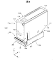
図1および図2は、本発明の第1実施形態における保護キャップ付きカートリッジ100を示す概略斜視図である。図1には、斜め下方から見たときの保護キャップ付きカートリッジ100が図示されている。図2には、斜め上方から見たときの保護キャップ付きカートリッジ100が図示されている。前記の「上方」および「下方」などの保護キャップ付きカートリッジ100の方向に関する記載は、後述するインクカートリッジ101を基準とする方向に対応している。図1および図2には、互いに直交し、インクカートリッジ101を基準とする方向を示す矢印X,Y,Zが図示されている。各矢印X,Y,Zは、後の説明において参照される各図に示されている矢印X,Y,Zと対応している。各矢印X,Y,Zが示す方向については後述する。
A. First embodiment:
[Overview of cartridge with protective cap]
1 and 2 are schematic perspective views showing a
保護キャップ付きカートリッジ100は、保護キャップ102が装着された状態のインクカートリッジ101(以下、単に「カートリッジ101」とも呼ぶ。)である。保護キャップ付きカートリッジ100は、本発明における液体収容容器の一実施形態である。カートリッジ101は、インクジェットプリンター(以下、単に「プリンター」とも呼ぶ。)に供給されるインクが収容されている液体収容体である。カートリッジ101は、プリンターのキャリッジ(後述)に着脱可能に装着される。保護キャップ102は、工場から出荷される前の未使用状態のカートリッジ101に装着される保護部材であり、カートリッジ101がプリンターに装着される前に、ユーザーによって取り外される。
The
以下では、カートリッジ101の構成を説明した後に、保護キャップ102の構成を説明する。そして、カートリッジ101に対する保護キャップ102の装着過程を説明し、保護キャップ付きカートリッジ100における保護キャップ102の装着状態の詳細を説明する。また、その後に、プリンターに対するカートリッジ101の装着についても説明する。
In the following, the configuration of the
[カートリッジの構成]
図3〜図10を参照して、カートリッジ101の構成を説明する。本実施形態のカートリッジ101は、いわゆる半密閉型のインクカートリッジであり、インクの消費にともなって、外部の空気が間欠的に内部に導入される構成を有している。以下では、カートリッジ101の外観上の構成を説明した後に、その内部構造を説明し、カートリッジ101における外部の空気の取り入れのメカニズムを説明する。
[Cartridge configuration]
The configuration of the
[カートリッジの外観上の構成]
図3は、カートリッジ101の正面側を斜め上方から見たときの概略斜視図である。図4は、カートリッジ101の背面側を斜め下方から見たときの概略斜視図である。図5は、カートリッジ101の概略左側面図である。図6は、カートリッジ101の概略右側面図である。図6には、吹き出し内に、カートリッジ101の基板部125が拡大して図示されている。図7は、カートリッジ101の概略底面図である。
[Appearance configuration of cartridge]
FIG. 3 is a schematic perspective view of the front side of the
カートリッジ101は、7つの壁部111〜117によって構成される略多面体形状を有している(図3,図4)。本明細書において、「壁部」は、平坦なものに限定されず、湾曲していてもよいし、屈曲部や段差部を有していてもよく、その表面に凹部や凸部、溝、傾斜面などを有していてもよい。
The
第1壁部111は、プリンターのキャリッジに装着されたときにカートリッジ101の底面を構成する壁部である(図4,図7)。第2壁部112は、第1壁部111に対向する位置にあり、プリンターのキャリッジに装着されたときにカートリッジ101の上面を構成する壁部である(図5)。本明細書において、壁部同士が「対向する」とは、壁部同士が互いに直接的に向き合っている状態と、壁部同士の間に他のものが介在して間接的に向き合っている状態の両方を意味する。
The
第3壁部113は、第1壁部111と第2壁部112との間において延在し、第1壁部111と第2壁部112とに交差する壁部である(図3,図5)。本明細書において「延在する」とは、ある方向に切れ間なく連続して延びている状態を意味する。延在している状態には、ある方向に延びている途中において折れ曲がっている状態や、湾曲している状態も含まれる。また、本明細書において、2つの壁部が「交差する」とは、2つの壁部同士が相互に実際に交差する状態と、一方の壁部が延在している方向の先に他方の壁部が位置している状態と、2つの壁部のそれぞれの延在している方向同士が交差する状態と、のいずれかの状態であることを意味する。よって、交差する壁部同士の間には、湾曲面を構成する面取り部などが介在していてもよい。
The
第4壁部114は、第2壁部112から、第2壁部112が第1壁部111に対向する方向に延在しており、第3壁部113と対向するとともに、第1壁部111と第2壁部112とに交差する壁部である(図4,図6)。第5壁部115は、第1壁部111と第2壁部112と第3壁部113と第4壁部114に交差する壁部である(図3)。第6壁部116は、第5壁部115に対向し、第1壁部111と第2壁部112と第3壁部113と第4壁部114に交差する壁部である(図4)。第7壁部117は、第1壁部111と第4壁部114との間において斜めに延在し、第1壁部111と第2壁部112と第5壁部115と第6壁部116とに交差している壁部である(図4,図6)。
The
本明細書では、便宜上、カートリッジ101において、第5壁部115によって構成されている面を「正面」と呼び、第6壁部116によって構成されている面を「背面」と呼ぶ。また、第5壁部115に正対したときに右側に位置する第4壁部114および第7壁部117によって構成される面を「右側面」と呼び、第5壁部115に正対したときに左側に位置する第3壁部113によって構成される面を「左側面」と呼ぶ。
In the present specification, for convenience, in the
ここで、矢印X,Y,Zが示す方向を説明する。矢印Xは、第3壁部113から第4壁部114に向かう方向を示している。矢印Yは、第6壁部116から第5壁部115に向かう方向を示している。矢印Zは、第1壁部111から第2壁部112に向かう方向を示している。矢印Zの方向は、保護キャップ付きカートリッジ100においてカートリッジ101のインク供給口(後述)と保護キャップ102のシール部(後述)とが対向する方向に一致しており、本発明における第1方向の下位概念に相当する。矢印Xの方向は、インク供給口から複数の接触部CPに向かう方向に一致しており、本発明における第2方向の下位概念に相当する。矢印Zの方向と矢印Xの方向とに直交している矢印Yに平行な方向が、本発明における第3方向の下位概念に相当する。なお、本明細書では、カートリッジ101に関して「上」または「下」と呼ぶときは、カートリッジ101がプリンターのキャリッジに装着された状態のときの重力方向を基準とする上下方向を意味している。
Here, the directions indicated by the arrows X, Y, and Z will be described. The arrow X indicates the direction from the
第1壁部111には、カートリッジ101に収容されているインクがプリンターに供給されるときに通過するインク供給部120が設けられている(図4,図7)。インク供給部120の構成の詳細については後述する。インク供給部120の外周には、外周壁部121が設けられている。外周壁部121に囲まれた領域内において、インク供給部120の左側面側には、連通口122が設けられている。外周壁部121および連通口122の機能については後述する。
The
第1壁部111には、さらに、位置決め部123が設けられている(図4,図7)。本実施形態では、位置決め部123は、矢印Zの方向に窪んでいる凹部として形成されている。位置決め部123は、カートリッジ101がプリンターのキャリッジに装着される際に、キャリッジに設けられている突起部が嵌合する。これによって、キャリッジにおけるカートリッジ101の配置位置および配置姿勢が規定される(詳細は後述)。本実施形態では、位置決め部123は、矢印Xの方向において、インク供給部120と基板部125との間に設けられており、第1壁部111における基板部125に寄った位置に設けられている。このように、基板部125に近い位置に位置決め部123が設けられていれば、基板部125の位置ずれに起因するプリンターの電極部に対する基板部125の電気的接触不良が抑制される。
The
第7壁部117には、基板部125が設けられている(図4,図6,図7)。基板部125は、第7壁部117に沿って配置されており、斜め下方に向いている(図4)。基板部125は、複数の端子125tを有している(図6)。本実施形態では、複数の端子125tが矢印Yの方向に所定の間隔をあけて配列されている列が、基板部125の表面に上下に2列、並列に形成されている。各端子125tは、カートリッジ101がプリンターのキャリッジに装着されたときにプリンター側の対応する端子のひとつと電気的に接続される。本明細書では、基板部125において、各端子125tがプリンター側の端子と電気的に導通する部位を「接触部CP」とも呼ぶ。つまり、基板部125は、複数の接触部CPを有している。
A
プリンターは、基板部125を介して、カートリッジ101の装着状態を示す電気信号や、カートリッジ101に収容されているインクの色や残量などのインクに関する情報をやりとりする。本実施形態では、インクに関する情報は、基板部125の裏面に設けられている記憶装置125sに記憶されている。記憶装置125sは後の説明で参照される図8に図示されている。
The printer exchanges information about ink such as an electric signal indicating a mounting state of the
カートリッジ101には、4つの被係合部131〜134が設けられている(図3,図4)。4つの被係合部131〜134は、保護キャップ102に設けられている係合部(後述)が係合する部位である。本明細書において「係合する」とは、対象物の移動方向が制限されるように実際に係り合っている状態を意味するほか、第2実施形態において説明するように、実際に係り合っていないまでも、係り合うことが可能になっている状態も含まれる。本実施形態のカートリッジ101では、矢印Zの方向に見たときに、4つの被係合部131〜134はそれぞれ第1壁部111の角部に位置している(図7)。
The
本実施形態では、第1被係合部131および第2被係合部132は、第1壁部111と第7壁部117とが交差している角部に設けられている(図4)。第1被係合部131および第2被係合部132は、カートリッジ101を矢印Xの逆方向に見たときに、基板部125の下側に位置しており、矢印Yの方向において、基板部125の両側に設けられている(図6)。第1被係合部131は、第5壁部115側に設けられており、第2被係合部132は、第6壁部116側に設けられている。
In the present embodiment, the first engaged
本実施形態では、第1被係合部131および第2被係合部132は、矢印Xの逆方向に窪み、矢印Xの方向に開口する凹部として形成されている。また、第1被係合部131は、矢印Yの方向にも開口しており、第2被係合部132は、矢印Yの逆方向にも開口している(図4,図6)。第1被係合部131および第2被係合部132はそれぞれ、矢印Zの方向に向き、保護キャップ102の対応する係合部が接触する係合面131s,132sを有している。
In the present embodiment, the first engaged
本実施形態では、第3被係合部133および第4被係合部134は、第3壁部113の下端に設けられている(図3)。第3被係合部133は、第5壁部115側の端部に設けられており、第4被係合部134は、第6壁部116側の端部に設けられている。本実施形態では、第3被係合部133および第4被係合部134は、矢印Xの方向に窪み、矢印Xの逆方向に開口する凹部として構成されている。第4被係合部134は、矢印Yの逆方向にも開口している。第3被係合部133および第4被係合部134はそれぞれ、矢印Zの方向に向き、保護キャップ102の対応する係合部が接触する係合面133s,134sを有している。
In the present embodiment, the third
第3壁部113には、リブ部135が設けられている(図3,図5)。リブ部135は、第3壁部113の壁面から矢印Xの逆方向に突起し、第3壁部113の壁面に沿って延びている。本実施形態では、リブ部135は、第1部位135aと第2部位135bとを有している。第1部位135aは、矢印Yの方向に延びている部位であり、第2部位135bは、第1部位135aの第6壁部116側の端部から矢印Zの逆方向に延びている部位である。リブ部135は、プリンターのキャリッジに設けられている凹部であるリブ受入部に係合し、カートリッジ101の配置位置を規定するとともに、キャリッジ上におけるカートリッジ101の移動を規制する移動規制部として機能する(詳細は後述)。リブ部135は、本発明における嵌合部の下位概念であり、本発明におけるリブの下位概念でもある。
A
第4壁部114には、嵌合部137が設けられている(図4,図6)。本実施形態では、嵌合部137は、第4壁部114の壁面から矢印Xの方向に突起し、第4壁部114の壁面上において延びているリブ状の凸部として構成されている。矢印Xの逆方向に見たときの嵌合部137の外周輪郭形状は、プリンターのキャリッジに設けられているレバー(後述)の形状に対応している。嵌合部137は、カートリッジ101が適切にキャリッジに装着される場合には、当該レバーに嵌合しつつ係合する(詳細は後述)。本実施形態では、カートリッジ101の嵌合部137およびそれに対応するキャリッジのレバーの形状は、インクの色ごとに予め決められている。これによって、カートリッジ101が、キャリッジにおける対応していない色の場所に誤って装着されてしまうことが抑制される。
A
第5壁部115には、カートリッジ101の内部に空気を導入するための通気部140が形成されている(図3)。通気部140は、通気孔141と、通気溝142と、外周凹部143と、を有している。通気孔141は、カートリッジ101の内部に連通する貫通孔である。カートリッジ101では、通気孔141を介して内部に空気が導入される(詳細は後述)。通気溝142は、第5壁部115の壁面において略直線状に延びている有底溝部である。通気溝142は、第1壁部111側の下端部近傍から矢印Zの方向に延びて通気孔141に接続されている。外周凹部143は、通気孔141と通気溝142の外周の領域を第5壁部115における他の部位よりも矢印Yの逆方向に窪ませることによって形成されている。外周凹部143が形成されていることによって、第5壁部115には、通気孔141および通気溝142の外周輪郭に沿ったリブ状の凸壁部144が形成されている。通気溝142および外周凹部143の機能については後述する。
The
第2壁部112には、シール145が貼付されている。シール145には、例えば、カートリッジ101の製造者や型番が表示される。シール145が貼付される位置は任意であり、シール145は、第2壁部112以外の壁部に貼付されてもよい。シール145は、例えば、第1壁部111や、第3壁部113、第4壁部114、第5壁部115、第6壁部116、第7壁部117のうちのひとつに貼付されてもよいし、7つの壁部111〜117のうちの2以上の壁部に跨がって貼付されてもよい。また、複数の壁部に複数のシールが貼付されてもよい。
A
[カートリッジの内部構成]
図8〜図10を、適宜、参照して、カートリッジ101の内部構造を説明する。図8は、カートリッジ101の分解概略斜視図である。カートリッジ101の本体部は、本体部材150と、蓋部材151と、で構成される。本体部材150は、矢印Yの方向に開口している箱状の部材である。本体部材150の外壁部が、カートリッジ101の第1壁部111と、第2壁部112と、第3壁部113と、第4壁部114と、第6壁部116と、第7壁部117とを構成している。
[Internal configuration of cartridge]
The internal structure of the
蓋部材151は、板状の部材である。蓋部材151は、本体部材150の開口部を閉塞するように取り付けられてカートリッジ101の第5壁部115を構成する。本体部材150と蓋部材151とは、ポリプロピレン等の合成樹脂の射出成形によって作製される。本体部材150の外壁面には、上述した基板部125や、シール145が取り付けられる。また、蓋部材151には、上述した通気部140が形成されている。
The
カートリッジ101では、本体部材150の凹部空間が、インクを収容するインク収容部152を構成する。インク収容部152の第5壁部115側は、本体部材150と蓋部材151との間に配置されているシート部材153によって閉塞される。シート部材153は、例えば、ナイロンとポリプロピレンを含む材料等の合成樹脂など、可撓性を有する膜状の樹脂部材によって構成される。
In the
シート部材153は、外周縁部153fと、本体部153bと、を有する。外周縁部153fは、枠状の平板な部位であり、本体部材150の開口端部に溶着または接着によって接合される。外周縁部153fには、貫通孔153hが形成されている。貫通孔153hは、後述するように、空気室170と空気導入口174とを連通する。本体部153bは、外周縁部153fによって囲まれているシート部材153の本体部位であり、外周縁部153fから第6壁部116側に全体が突出して、矢印Yの逆方向に窪んでいる凹部を形成している。
The
インク収容部152には、インクが収容されている状態において、インク収容部152内を所定の負圧状態にするための圧力調整機構155が設けられている。圧力調整機構155は、受圧板156と、付勢部材157と、を備える。受圧板156は、インク収容部152においてシート部材153の本体部153bに接触して配置される平板な板状部材である。受圧板156は、ポリプロピレン等の合成樹脂や、ステンレス等の金属によって構成される。受圧板156は、シート部材153の本体部153bにおける凹部の底面に対応する形状を有しており、当該底面に接合されている。
The ink
付勢部材157は、例えば、コイルばねによって構成される。付勢部材157は、受圧板156と第6壁部116との間に配置され、インク収容部152内の容積が拡大される方向である矢印Yの方向に受圧板156を付勢する。本実施形態では、付勢部材157は、受圧板156を矢印Yの方向に付勢している。付勢部材157によって受圧板156が第5壁部115側へと押されることによって、受圧板156の外周縁においてシート部材153が撓み、シート部材153の凹部が第5壁部115側に潰れた状態になる。これによって、インク収容部152にインクが充填されているときには、インク収容部152内は所定の負圧の状態となる。
The urging
インク収容部152の底面を構成している第1壁部111には、インク供給部120を構成するための開口部160が設けられている。開口部160は、第1壁部111のほぼ中央の位置において第1壁部111を矢印Zの方向に貫通する貫通孔として形成されている。開口部160に、フィルター部161と、フォーム部162と、板バネ部163と、が下方から取り付けられることによって、インク供給部120が構成される。
The
図9は、インク供給部120の構成を説明するための概略断面図である。図9には、図5に示されているA−A切断におけるカートリッジ101の概略断面が図示されている。図9では、インク収容部152内における他の構造の図示は、便宜上、省略されている。フィルター部161は、開口部160を覆うように配置されており、カートリッジ101の外側において開口部160の周縁部に溶着されている。フィルター部161は、インクが透過可能な透液性を有する膜状の部材によって構成されている。フィルター部161は、例えば、織布や不織布、発泡性樹脂(フォーム)によって構成される。
FIG. 9 is a schematic cross-sectional view for explaining the configuration of the
フォーム部162は、フィルター部161のインク収容部152側の面上に配置されている。フォーム部162は、多孔質部材によって構成されており、内部に、インク収容部152のインクが含浸する。フォーム部162は、インクを自身の内部において全体に拡散させつつ、フィルター部161に供給する。フォーム部162は、例えば、ポリエチレンテレフタレート等の合成樹脂により構成される。
The
板バネ部163は、金属板によって構成されており、インク収容部152とフォーム部162との間に配置されている。板バネ部163は、2枚の板バネが交差している形状を有している。板バネ部163は、上端が開口部160の内周面に形成された段差部に係合するように配置され、下端がフォーム部162に接触することによって、フィルター部161およびフォーム部162を矢印Zの逆方向に付勢する。板バネ部163は、開口部160からフォーム部162へのインクの流通を妨げないような形状を有している。
The
ここで、インク供給部120のフィルター部161は、カートリッジ101がプリンターのキャリッジに装着されたときには、接触領域ARにおいて、キャリッジのインク導入部(後述)に接触する。インク収容部152のインクは、フィルター部161の接触領域ARを通過して、プリンターへと供給される。本明細書では、インクが通過する接触領域ARを「インク供給口164」とも呼ぶ。図7および図9には、インク供給口164の形成領域の一例が図示されている。インク供給口164は、本発明における液体供給口の下位概念に相当する。
Here, the
上述したように、インク供給部120の外周には、外周壁部121が形成されている。カートリッジ101がプリンターのキャリッジに装着されたときには、外周壁部121がキャリッジに設けられているシール部(後述)と接触し、インク供給部120の外周にシールラインが形成される。当該シールラインに囲まれた閉空間内には、上述したように、インク供給部120とともに、連通口122が形成されている。連通口122は、第1壁部111内に形成されている連通路166を介して空気室170(図8)に連通している。これによって、カートリッジ101がキャリッジに装着されているときに、シールラインに囲まれた閉空間と外部との圧力差が略一定に維持されるため、当該閉空間内の圧力変動に起因するインク供給部120からのインクの漏洩が抑制される。
As described above, an outer
カートリッジ101では、シート部材153と第5壁部115との間の空間が、空気を収容する空気室170として機能する(図8)。空気室170には、第5壁部115に設けられている通気部140の通気孔141を介して外部の大気が導入される。カートリッジ101には、インク収容部152におけるインクの消費にともなって、空気室170の空気をインク収容部152内に導入するための大気弁171が設けられている。大気弁171は、弁座173と、弁部材175と、コイルばね178と、を備える。
In the
弁座173は、受圧板156とは干渉しないように、インク収容部152における第2壁部112と第4壁部114とが交わる角部に配置されている。弁座173は、シート部材153側に凹部173cを有し、凹部173cの開口端面173tは、シート部材153の外周縁部153fの角部に気密に貼り付けられている。弁座173の凹部173cは、シート部材153の貫通孔153hと連通している。弁座173の凹部173cの底部には、弁座173を矢印Yの方向に貫通する空気導入口174が形成されている。弁座173は、例えば、ポリプロピレン等の合成樹脂により構成される。
The
弁部材175は、弁体部176と、レバー部177と、を有する。弁体部176は、弁部材175の端部部位であり、弁座173の空気導入口174と対向する位置に配置される。レバー部177は、弁体部176から略L字状に延びている延伸部位である。レバー部177は、弁体部176から矢印Yの逆方向に延びた後に屈曲して、受圧板156と矢印Yの方向において対向する位置まで延びている。弁部材175は、弁体部176側を支点としてレバー部177が回転移動するように取り付けられている。弁部材175は、例えば、ポリプロピレン等の合成樹脂によって構成される。弁部材175は、エラストマー等の弾性部材とポリプロピレン等の合成樹脂とを用いて2色成型により構成されてもよい。
The
コイルばね178は、弁部材175の弁体部176と第6壁部116との間に配置され、弁体部176を弁座173の空気導入口174に押しつけるように付勢する。コイルばね178に付勢されることによって、弁部材175の弁体部176は、弁座173の空気導入口174の周縁部に接触し、空気導入口174を気密に閉塞する。
The
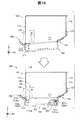
[カートリッジにおける外部の空気の取入メカニズム]
図10は、カートリッジ101において外部の空気が取り入れられるメカニズムを説明するための概略図である。図10の(a)〜(c)にはそれぞれ、矢印Zの逆方向に沿って見たときのカートリッジ101の内部構造が模式的に図示されている。図10では、便宜上、インク供給部120の図示は省略されている。
[External air intake mechanism in the cartridge]
FIG. 10 is a schematic view for explaining a mechanism by which external air is taken into the
インク収容部152に規定量のインクが収容されている満タンの状態では、上述したように、付勢部材157によって、受圧板156が第5壁部115側に押圧されて、インク収容部152の容積が押し広げられた状態となる(図10の(a))。このとき、受圧板156は、第5壁部115に最も接近した位置に位置している。また、インク収容部152内は、所定の負圧の状態になっており、受圧板156の外周においてシート部材153の一部がインク収容部152内へと引き込まれている。その他に、この状態においては、弁部材175の弁体部176によって弁座173の空気導入口174が閉塞されて、インク収容部152は空気室170に対して気密に封止されている。また、弁部材175のレバー部177は受圧板156から離間した位置にある。
In a full tank state in which a specified amount of ink is contained in the
開口部160を介してインク供給部120からプリンターにインクが供給され、インク収容部152のインクが消費されていくと、空気室170とインク収容部152との圧力差が増大し、受圧板156は第6壁部116側へと移動していく(図10の(b))。受圧板156が、弁部材175のレバー部177の先端部の位置まで到達し、レバー部177を押圧すると、弁部材175が回転移動して、弁体部176による空気導入口174の封止状態が解除され、大気弁171が開弁状態になる。これによって、空気室170の空気がインク収容部152に導入されるとともに、カートリッジ101の外部の空気が通気孔141を介して空気室170に導入される。
When ink is supplied from the
インク収容部152に空気が導入されて、空気室170とインク収容部152との間の圧力差が低減されるにつれて、付勢部材157の付勢力により、受圧板156は第5壁部115側へと移動する(図10の(c))。受圧板156が弁部材175のレバー部177から離間すると、コイルばね178の付勢力によって、空気導入口174が再び弁体部176に封止され、大気弁171が閉弁状態に戻る。
As air is introduced into the
このように、カートリッジ101では、インク収容部152のインクの消費に伴って、インク収容部152内の負圧が大きくなったときには、一時的に大気弁171が開弁状態になる。そして、インク収容部152に空気が導入されて、インク収容部152内が適切な負圧状態になったときに、大気弁171が再び閉弁状態に戻る。これによって、インク収容部152内の圧力が適切な圧力範囲内に維持されるため、インク収容部152内の負圧が大きくなりすぎることによるインクの供給不良の発生が抑制される。
As described above, in the
[保護キャップの構成]
図11〜図14と、図1および図2を参照して、保護キャップ102の構成を説明する。図11は、保護キャップ102の上面側を示す概略斜視図である。図12は、保護キャップ102の下面側を示す概略斜視図である。図13は、保護キャップ102を上面に正対する方向に見たときの概略上面図である。図14は、保護キャップ102の第1側壁部201に正対する方向に見たときの概略側面図である。図13には、便宜上、保護キャップ102がカートリッジ101に取り付けられたときのインク供給部120と外周壁部121と連通口122と位置決め部123の位置が一点鎖線によって図示されている。図11〜図14には、図1および図2に対応するように、保護キャップ102が取り付けられた状態のカートリッジ101を基準とする矢印X,Y,Zが図示されている。保護キャップ102の「上面」は、カートリッジ101が装着される側の面を意味しており、「下面」はその反対側の面を意味している。
[Protective cap configuration]
The configuration of the
保護キャップ102は、カートリッジ101の第1壁部111を含む下端部全体をほぼ被覆する本体部を構成する土台部103を有している(図1)。土台部103は、ポリプロピレンなどの合成樹脂の射出成形による一体成形によって作製される。土台部103は、底壁部200と、4つの側壁部201,202,203,204と、基板側係合部205と、レバー式係合部206と、を備える(図11,図12)。
The
底壁部200は、略長方形形状を有する板状の部位であり(図12,図13)、カートリッジ101の第1壁部111と対向する(図1)。保護キャップ付きカートリッジ100では、カートリッジ101のインク供給部120および位置決め部123は底壁部200によって被覆される(図13)。底壁部200は、本発明における本体部の下位概念に相当する。
The
第1側壁部201および第2側壁部202はそれぞれ、底壁部200の長辺を構成している端部から矢印Zの方向に延びている壁部である(図11)。第1側壁部201および第2側壁部202は、互いにほぼ同じ形状を有しており、底壁部200の長辺のほぼ全体にわたって矢印Yの方向に並列に延びている。第1側壁部201は、カートリッジ101の第5壁部115の下端部と対向し、第2側壁部202は、カートリッジ101の第6壁部116の下端部と対向する(図1,図2)。
Each of the first
第3側壁部203および第4側壁部204はそれぞれ、底壁部200の短辺を構成している端部から矢印Zの方向に延びている壁部である(図11)。第3側壁部203は、矢印Zの方向においてカートリッジ101の第7壁部117の下端に対向する位置に設けられている(図1)。第4側壁部204は、その上端面が、矢印Zの方向において、カートリッジ101における第1壁部111の第3壁部113側の端部と対向する位置に設けられている(図2)。第3側壁部203および第4側壁部204の高さはそれぞれ同程度であり、いずれも第1側壁部201および第2側壁部202の高さよりも低い。第3側壁部203および第4側壁部204の矢印Yの方向における両端は、第1側壁部201および第2側壁部202の下端部に連結されている。
Each of the third
基板側係合部205は、第3側壁部203の上端に設けられている(図11)。基板側係合部205は、保護キャップ102にカートリッジ101が取り付けられたときに、矢印Zの方向において、基板部125を有する第7壁部117の下端に対向する(図1)。
The substrate-
基板側係合部205は、第1係合部207と、第2係合部208と、を含む(図11)。第1係合部207と第2係合部208とはそれぞれ、第3側壁部203の上端から矢印Zの方向に延びる柱状の部位として形成されている。第1係合部207は、第1側壁部201に寄った位置に設けられており、第2係合部208は、第2側壁部202に寄った位置に設けられている。各係合部207,208は、各側壁部201,202の上端の高さ位置の近傍まで延びており、その先端には、矢印Xの逆方向に突出する爪状の突起部207t,208tが設けられている。各突起部207t,208tは、矢印Zの逆方向に向く平面である係合面207s,208sを有している。
The substrate-
保護キャップ102にカートリッジ101が取り付けられたときに、第1係合部207は、突起部207tにおいてカートリッジ101の第1被係合部131に係合し、第2係合部208は、突起部208tにおいて第2被係合部132に係合する。各係合部207,208と各被係合部131,132との係合のメカニズムについては後述する。
When the
レバー式係合部206は、第4側壁部204よりも矢印Xの逆方向側に設けられている(図11)。レバー式係合部206は、保護壁部210と、連結部211と、操作部212と、を有する(図12)。保護壁部210は、矢印Y,Zの二方向に延在している壁部であり、カートリッジ101の第3壁部113の下端部に対向する。
The lever
保護壁部210のカートリッジ101と対向する側の壁面の上端には、第3係合部213と第4係合部214とが設けられている。第3係合部213と第4係合部214とはそれぞれ、保護壁部210の壁面から矢印Xの方向に突出する突起部として形成されており、矢印Zの逆方向に向く平面である係合面213s,214sを有している。第3係合部213は、カートリッジ101の第3被係合部133に係合し、第4係合部214は、第4被係合部134に係合する。各係合部213,214と対応する各被係合部133,134との係合のメカニズムについては後述する。
A third
保護壁部210は、複数の連結部211を介して、底壁部200に連結されている(図14)。本実施形態では、矢印Xの方向における幅が広い連結部211と、矢印Xの方向における幅が狭い連結部211の2つが設けられている(図12)。各連結部211は、底壁部200と第4側壁部204との間の角部から、矢印Xの逆方向に延びた後に、矢印Zの方向に湾曲して延びて、保護壁部210の下端に連結されている。本実施形態では、連結部211は、弾性変形が可能であり、保護壁部210は、連結部211の湾曲部を支点として、矢印Yの方向に弾性的に回転移動が可能である。保護壁部210および連結部211が本発明における可動部の下位概念に相当する。
The
操作部212は、保護壁部210の壁面から矢印Xの逆方向に延びる壁部として形成されている。操作部212は、ユーザーが保護キャップ102をカートリッジ101から取り外す際に利用される。ユーザーは、操作部212に指をかけて、保護壁部210を矢印Xの逆方向側に回転移動させることによって、保護キャップ102をカートリッジ101から取り外すことができる。操作部212は、ユーザーが操作しやすいように、わずかに斜め上方に傾斜して矢印Yの逆方向に延びている(図14)。また、ユーザーが指をかけやすいように、操作部212の矢印Yの方向における幅は、保護壁部210の矢印Yの方向における幅とほぼ同じに構成されており、上面側に滑り止めとして機能するリブ状の凸部が形成されている(図11)。
The operating
4つの側壁部201〜204に囲まれている底壁部200の上面側の凹部には、シール部220が配置されている(図11)。シール部220は、土台部103よりも軟らかく、弾性を有する樹脂材料によって構成されている。シール部220は、例えば、エラストマーなどによって構成される。シール部220は、枠状部位221と、仕切壁部222と、を有する(図13)。
A
枠状部位221は、カートリッジ101の第1壁部111に設けられている外周壁部121(図7)に対応する略四角枠形状を有する(図13)。カートリッジ101が保護キャップ102に装着されたときに、枠状部位221が外周壁部121の上端面全体に当接することによって、インク供給部120の外周にシールラインが形成される。これによって、保護キャップ付きカートリッジ100の外部にインクが漏洩してしまうことが抑制される。
The frame-shaped
仕切壁部222は、枠状部位221の枠内を2つの領域に仕切るように、枠状部位221の枠内を矢印Xの方向に横断している壁部である(図13)。仕切壁部222は、枠状部位221よりも矢印Zの方向に突出している(図11)。カートリッジ101が保護キャップ102に装着されたときには、仕切壁部222の上端面が、インク供給部120の矢印Yの逆方向側の端部に接触して受け止める。そして、仕切壁部222の矢印Yの方向における両端面が第1壁部111の外周壁部121の内周面と対向する(図13)。
The
保護キャップ付きカートリッジ100においては、仕切壁部222は、外周壁部121の内周側に嵌まり込むことによって、矢印Xの方向におけるカートリッジ101の位置を規定する位置決め部として機能している。また、保護キャップ付きカートリッジ100においては、枠状部位221の枠内の領域のうち、仕切壁部222よって仕切られた矢印Xの方向側の領域に、インク供給部120が位置し、矢印Xの逆方向側の領域に、連通口122が位置している。従って、たとえインク供給部120からインクが漏洩したとしても、そのインクが連通口122に流入し、連通口122が閉塞されてしまうことが抑制される。
In the
本実施形態では、底壁部200の上面側の壁面に、矢印Zの方向に突出する2つの並列なリブ223,224が設けられている。第1リブ223は、シール部220と第3側壁部203との間において、矢印Xの方向に延びており、第1側壁部201と第2側壁部202とに連結されている。第2リブ224は、シール部220と第4側壁部204との間において、矢印Yの方向に延びており、第1側壁部201と第2側壁部202とに連結されている。2つのリブ223,224はいずれも、第3側壁部203および第4側壁部204と同程度の高さを有している。
In the present embodiment, two
保護キャップ102の土台部103は、2つのリブ223,224が設けられていることによって、その強度が高められている。また、保護キャップ付きカートリッジ100においては、2つのリブ223,224によって、シール部220のシール領域内に漏洩したインクが外部に流出することが堰き止められる。従って、保護キャップ付きカートリッジ100から外部にインクが漏洩してしまうことがさらに抑制されている。
The strength of the
[カートリッジに対する保護部材の装着過程]
図15〜図17を参照して、カートリッジ101に対する保護キャップ102の装着過程を説明する。図15および図16は、カートリッジ101に対する保護キャップ102の取り付け工程を工程順に示す概略図である。第1工程では、カートリッジ101の第7壁部117の壁面に、保護キャップ102における基板側係合部205の第1係合部207および第2係合部208を接触させる(図15の上段)。より具体的には、各係合部207,208の各突起部207t,208tの先端をそれぞれ、基板部125の両脇において、第7壁部117の壁面に接触させる。
[Process of attaching protective member to cartridge]
The process of attaching the
第2工程では、各係合部207,208の各突起部207t,208tの先端を第7壁部117の壁面に接触させたまま、第7壁部117の壁面に沿って、下方へと滑らせていく(図15の中段)。すると、第1係合部207の突起部207tの先端が第1被係合部131に嵌まるとともに、第2係合部208の突起部208tの先端が第2被係合部132に嵌まり、保護キャップ102がカートリッジ101に引っかかった状態になる(図15の下段)。図15の下段では、各係合部207,208が対応する被係合部132,133に嵌まっている状態を示すために、一部が部分断面図によって表されている。
In the second step, the tips of the
上述したように、本実施形態のカートリッジ101では、第1被係合部131は矢印Yの方向に開口しており、第2被係合部132は矢印Yの逆方向に開口している。そのため、この段階において、保護キャップ102の位置が、矢印Yの方向、または、矢印Yの逆方向にわずかにずれていたとしても、保護キャップ102の各係合部207,208が、対応する被係合部131,132に係合することが可能である。
As described above, in the
第3工程では、この状態において、第1係合部207および第2係合部208を支点として、保護キャップ102をカートリッジ101に向かって上方に回転移動させる。そして、保護キャップ102の第3係合部213および第4係合部214をそれぞれ第3壁部113の下端に接触させる(図16の上段)。
In the third step, in this state, the
第4工程では、保護キャップ102をそのまま上方に回転移動させることによって、レバー式係合部206の保護壁部210を、連結部211を支点として矢印Xの逆方向側に回転移動させる。これによって、第3係合部213および第4係合部214は、いったん、カートリッジ101から離れる方向に移動し、第3壁部113の壁面に乗り上げて、カートリッジ101の第3被係合部133および第4被係合部134に嵌まる(図16の下段)。このようにして、保護キャップ102の4つの係合部207,208,213,214がそれぞれ被係合部131〜134のうちの対応するひとつに係合し、保護キャップ付きカートリッジ100が構成される。
In the fourth step, the
図16の下段では、図15の下段と同様に、第1係合部207が対応する第1被係合部131に係合している状態を示すために、一部が部分断面図によって表されている。保護キャップ付きカートリッジ100では、第1係合部207の係合面207sが第1被係合部131の係合面131sと矢印Zの方向に対向して面接触している。第2係合部208の係合面208sと第2被係合部132の係合面132sも同様である。
In the lower part of FIG. 16, as in the lower part of FIG. 15, a part is shown by a partial cross-sectional view in order to show a state in which the first engaging
図17は、図16の下段に示されているB−B切断における保護キャップ付きカートリッジ100の概略断面図である。保護キャップ付きカートリッジ100では、保護キャップ102の第3係合部213の係合面213sと、カートリッジ101の第3被係合部133における係合面133sと、が矢印Zの方向に対向して面接触している。また、第4係合部214の係合面214sと第4被係合部134の係合面134sも同様である。
FIG. 17 is a schematic cross-sectional view of the
上述したように、本実施形態のカートリッジ101では、第4被係合部134は矢印Yの逆方向にも開口している。そのため、図16の上段に示されている第3工程の段階において、保護キャップ102の第4係合部214の位置が、規定の位置から矢印Yの逆方向にずれていたとしても、第4係合部214は第4被係合部134に係合することが可能である。
As described above, in the
[保護キャップの装着状態の詳細]
図18〜図21と、これまでに参照した各図とを参照して、保護キャップ102の各構成部によるカートリッジ101の保護や、カートリッジ101に対する保護キャップ102の装着性についての詳細を説明する。
[Details of wearing protective cap]
With reference to FIGS. 18 to 21 and the respective drawings referred to so far, details of the protection of the
(1)カートリッジの基板部に応じた第1係合部および第2係合部の構成:
図18は、保護キャップ付きカートリッジ100を第4壁部114に正対する方向から見たときの概略右側面図である。図19は、保護キャップ付きカートリッジ100を第5壁部115に正対する方向に見たときの概略正面図である。
(1) Configuration of the first engaging portion and the second engaging portion according to the substrate portion of the cartridge:
FIG. 18 is a schematic right side view of the
本実施形態の保護キャップ付きカートリッジ100では、矢印Xの逆方向に見たときに、基板部125および基板部125上の複数の接触部CPは、矢印Yの方向において、第1係合部207と第2係合部208の間に位置している(図18)。この配置構成であれば、基板部125および複数の接触部CPは、第1係合部207と第2係合部208に矢印Yの方向の両側から保護される。よって、カートリッジ101がプリンターのキャリッジに装着されたときの電気的接触不良の発生が抑制される。
In the
また、保護キャップ102の装着過程(図15)において、基板部125の接触部CPを挟むように、第1係合部207および第2係合部208を配置すればよいため、カートリッジ101に対する保護キャップ102の位置決めが容易化される。加えて、第1係合部207および第2係合部208をそれぞれ、矢印Yの方向における基板部125の両端部に沿って第7壁部117の壁面上を滑らせることによって、対応する被係合部131,132へと円滑に誘導することができる。よって、カートリッジ101に対する保護キャップ102の装着がさらに容易化されている。
Further, in the mounting process of the protective cap 102 (FIG. 15), the first engaging
本実施形態の保護キャップ付きカートリッジ100では、保護キャップ102の第1係合部207および第2係合部208の間の矢印Yの方向における距離Deは、複数の接触部CPの矢印Yの方向における最大距離Dcよりも大きい(下記不等式(A))。
De>Dc …(A)
ここで、「複数の接触部CPの矢印Yの方向における最大距離Dc」は、矢印Yの方向において、最も外側に位置する両端の接触部CPの間の距離を意味している。本実施形態では、最大距離Dcは、下段の列において両端に位置する各端子125tの接触部CP間の距離である(図6,図18)。上記不等式(A)の関係を満たしていれば、保護キャップ102の装着過程において、カートリッジ101が、保護キャップ102に対して矢印Xの方向において、わずかにずれた位置に配置されたとしても、係合部207,208が、複数の接触部CPに接触してしまうことが抑制される。
In the
De> Dc ... (A)
Here, "the maximum distance Dc in the direction of the arrow Y of the plurality of contact portions CP" means the distance between the contact portions CP at both ends located on the outermost side in the direction of the arrow Y. In the present embodiment, the maximum distance Dc is the distance between the contact portions CP of the
本実施形態の保護キャップ付きカートリッジ100では、前記の距離Deと前記の最大距離Dcとの間の差は、第1被係合部131の矢印Xの方向における幅W1よりも小さい(下記不等式(B))。
De−Dc<W1 …(B)
上記の不等式(B)の関係が満たされていることによって、保護キャップ102の装着過程において、各係合部207,208を、矢印Yの方向において各接触部CPの両外側に位置させれば、第1係合部207を、第1被係合部131に係らせることができる。よって、第1係合部207と第1被係合部131との係合が容易化される。
In the
De-Dc <W1 ... (B)
By satisfying the relationship of the above inequality (B), if the engaging
本実施形態の保護キャップ付きカートリッジ100では、上記の不等式(A),(B)において、最大距離Dcを、基板部125の矢印Xの方向における幅Wbに置きかえた下記の不等式(A’),(B’)の関係についても満たされている。
De>Wb …(A’)
De−Wb<W1 …(B’)
In the
De> Wb ... (A')
De-Wb <W1 ... (B')
不等式(A’),(B’)の関係が満たされていることによって、本実施形態の保護キャップ付きカートリッジ100では、保護キャップ102の装着過程において、係合部207,208が、基板部125に接触してしまうことが抑制される。また、保護キャップ102の装着過程において、各係合部207,208を、矢印Yの方向における基板部125の両端に位置させれば、第1係合部207を、第1被係合部131に係らせることができる。よって、第1係合部207と第1被係合部131との係合が、さらに容易化される。
By satisfying the relationship of the inequalities (A') and (B'), in the
加えて、本実施形態の保護キャップ付きカートリッジ100では、基板部125および基板部125上の複数の接触部CPは、第7壁部117と保護キャップ102の第3側壁部203とが交差している奥まった角部に位置している(図19)。これによって、基板部125および基板部125上の複数の接触部CPに対する保護性が高められている。特に、本実施形態の保護キャップ付きカートリッジ100では、基板部125が、第7壁部117の下端に位置しており、より保護キャップ102に近接して配置されている。従って、基板部125および基板部125上の複数の接触部CPに対する保護性が、さらに高められている。
In addition, in the
図20は、保護キャップ102の第1係合部207および第2係合部208のそれぞれの幅について説明するための概略図である。図20の左欄には、保護キャップ付きカートリッジ100において、カートリッジ101と保護キャップ102とを、矢印Zの方向に分離させた状態が図示されている。図20の左欄では、矢印Yの方向におけるカートリッジ101の第1被係合部131と第2被係合部132との間の中心と、矢印Yの方向における保護キャップ102の第1係合部207と第2係合部208との間の中心と、が矢印Yの方向においてほぼ揃っている。ここで、「ほぼ揃っている」とは、例えば、1.0mm以下のずれが許容されることを意味している。
FIG. 20 is a schematic view for explaining the widths of the first engaging
図20の右欄には、図20の左欄の状態から、カートリッジ101を、保護キャップ102に対して、矢印Xの方向にオフセットさせた状態が図示されている。図20の右欄では、矢印Yの方向において、基板部125の第6壁部116側の端部の位置が、第2係合部208の第1係合部207側の端部の位置と、ほぼ揃っている。
The right column of FIG. 20 shows a state in which the
図20の左欄の状態、すなわち、保護キャップ102がカートリッジ101に適切に装着された状態において、矢印Yの方向における基板部125と第1係合部207との間の離間距離をD1とし、基板部125と第2係合部208との間の離間距離をD2とする。また、矢印Yの方向におけるカートリッジ101の第1被係合部131の幅をW1とし、矢印Yの方向における第1被係合部131と基板部125との間の最短距離をW2とする。このとき、本実施形態の保護キャップ付きカートリッジ100では、下記の不等式(C)の関係が満たされている。
W2<D1+D2<W1+W2 …(C)
In the state of the left column of FIG. 20, that is, in the state where the
W2 <D1 + D2 <W1 + W2 ... (C)
ここで、図20の右欄に示されているように、カートリッジ101が保護キャップ102に対して矢印Yの逆方向にずれた状態であるときの矢印Yの方向における基板部125と第1係合部207との間の離間距離をD1’とする。D1’は、図20の左欄におけるD1とD2とを加算した距離に相当する(D1’=D1+D2)。上記の不等式(C)の関係が満たされていれば、カートリッジ101が保護キャップ102に対して、図20の右欄に示されているように、矢印Yの逆方向にずれた状態で装着されたとしても、第1係合部207を第1被係合部131に係合させることができる。よって、保護キャップ102のカートリッジ101に対する装着性が高められている。
Here, as shown in the right column of FIG. 20, the
また、保護キャップ102において、矢印Yの方向における第1係合部207の幅をW3とする。このとき、本実施形態の保護キャップ付きカートリッジ100では、下記の不等式(D)の関係が満たされている。
W3>W2 …(D)
Further, in the
W3> W2 ... (D)
上記の不等式(D)の関係が満たされていれば、カートリッジ101に保護キャップ102を取り付けるときに、第1係合部207が、第1被係合部131に係合しないまま、基板部125と第1被係合部131との間を通過してしまうことが抑制される。
If the relationship of the above inequality (D) is satisfied, when the
さらに、保護キャップ102において、矢印Yの方向における第2係合部208の幅をW4とし、カートリッジ101において、矢印Yの方向における基板部125と第2被係合部132との間の距離をW5とする。このとき、本実施形態の保護キャップ付きカートリッジ100では、下記の不等式(E)の関係が満たされている。
W4>W5 …(E)
Further, in the
W4> W5 ... (E)
上記の不等式(E)の関係が満たされていれば、カートリッジ101に保護キャップ102を取り付けるときに、第2係合部208が、第2被係合部132に係合しないまま、基板部125と第2被係合部132との間を通過してしまうことが抑制される。
If the relationship of the above inequality (E) is satisfied, when the
以上のように、本実施形態の保護キャップ付きカートリッジ100によれば、第1係合部207および第2係合部208によって、接触部CPが保護される。また、カートリッジ101に対する保護キャップ102の装着過程において、第1係合部207および第2係合部208の位置決めや、対応する被係合部131,132への係合が容易化されており、カートリッジ101に対する保護キャップ102の装着性が高められている。
As described above, according to the
(2)位置決め部に対する4つの係合部の構成:
図13からも理解できるように、本実施形態の保護キャップ付きカートリッジ100では、矢印Zの方向に見たときに、第1壁部111に設けられている位置決め部123が、保護キャップ102の底壁部200によって被覆される。従って、プリンターのキャリッジに装着される前に位置決め部123に塵芥などの異物が入り込んでしまうことが抑制され、カートリッジ101のキャリッジに対する装着性が低下してしまうことが抑制される。
(2) Configuration of four engaging portions with respect to the positioning portion:
As can be understood from FIG. 13, in the
(3)第3係合部と第4係合部の配置構成:
図17に示されているように、本実施形態の保護キャップ付きカートリッジ100では、矢印Xの方向に見たときに、矢印Yの方向において、保護キャップ102の第3係合部213と第4係合部214との間に、リブ部135が位置している。保護キャップ102をカートリッジ101に取り付ける際には、カートリッジ101のリブ部135の両側に、第3係合部213と第4係合部214が位置するように、カートリッジ101に対する保護キャップ102の配置位置を決定すればよい。つまり、保護キャップ付きカートリッジ100では、保護キャップ102をカートリッジ101に取り付けの際に、リブ部135を基準として、保護キャップ102の第3係合部213と第4係合部214の位置を決めることができる。従って、保護キャップ102のカートリッジ101への取り付けが容易化されている。
(3) Arrangement configuration of the third engaging portion and the fourth engaging portion:
As shown in FIG. 17, in the
また、上述したように、カートリッジ101への保護キャップ102の取り付けの際には、第3係合部213および第4係合部214を対応する被係合部133,134に係合させる前に、カートリッジ101の第3壁部113の下端に接触させている(図16の上段)。このように、保護キャップ付きカートリッジ100では、第3係合部213および第4係合部214が、カートリッジ101への正しい装着手順のガイドとしても機能する。従って、カートリッジ101への保護キャップ102の取り付けの際の利便性が高められている。
Further, as described above, when attaching the
(4)4つの係合部の配置構成:
図13に示されているように、本実施形態の保護キャップ付きカートリッジ100では、インク供給口164を含むインク供給部120は、矢印Zの方向に沿って見たときに、4つの係合部207,208,213,214に囲まれた位置に位置している。これによって、保護キャップ付きカートリッジ100では、インク供給部120に対するシール部220の配置が安定化している。そのため、シール部220によるインク供給部120に対するシール性が高められているとともに、インク供給部120からのシール部220の離脱が抑制され、カートリッジ101のインク供給部120からのインクの漏洩が抑制される。
(4) Arrangement configuration of four engaging parts:
As shown in FIG. 13, in the
また、本実施形態の保護キャップ付きカートリッジ100では、4つの係合部207,208,213,214がそれぞれ、第3壁部113または第7壁部117の下端に位置しており、シール部220に対してほとんど同じ高さ位置に位置している。そのため、インク供給部120に対するシール部220の配置位置がより安定化されている。
Further, in the
加えて、本実施形態の保護キャップ付きカートリッジ100では、4つの係合部207,208,213,214がそれぞれ、カートリッジ101の第1壁部111における4つの角部に1つずつ対応して設けられている。そのため、カートリッジ101に対して保護キャップ102がバランスよく取り付けられた状態となるため、カートリッジ101からの保護キャップ102の予期せぬ脱落が抑制されている。
In addition, in the
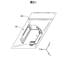
(5)保護キャップによるカートリッジの梱包性の向上:
図19に示されているように、本実施形態の保護キャップ付きカートリッジ100では、矢印Xの方向に沿って見たときに、カートリッジ101の通気部140が有する通気溝142の下端が、保護キャップ102の第1側壁部201と重なっている。これによって、以下に説明するように、保護キャップ付きカートリッジ100の工場出荷時に、カートリッジ101内の圧力を適切な負圧状態にすることができる。
(5) Improvement of cartridge packability by protective cap:
As shown in FIG. 19, in the
図21は、保護キャップ付きカートリッジ100の工場出荷時における状態の一例を示す概略図である。保護キャップ付きカートリッジ100は、工場出荷時に、可撓性を有するシート状の樹脂部材(例えば、ポリエチレンやポリ塩化ビニルなど)によって構成された袋状の梱包部材300に封入される場合がある。本実施形態の保護キャップ付きカートリッジ100であれば、梱包部材300に収容されている状態において、梱包部材300内の空気を吸引することによって、通気部140を介してカートリッジ101内の空気も吸引することができる。よって、梱包部材300内およびカートリッジ101内を効率的に所望の負圧状態にすることができる。
FIG. 21 is a schematic view showing an example of the state of the
また、本実施形態の保護キャップ付きカートリッジ100であれば、上述したように、矢印Xの方向において、通気部140の一部が、保護キャップ102の第1側壁部201と重なる位置にある。そのため、上記のように梱包部材300内を負圧にしたときに、可撓性を有する梱包部材300の一部が通気部140に密着して通気部140を封止してしまうことが、可撓性が比較的低い保護キャップ102の第1側壁部201によって抑制される。従って、カートリッジ101内が所望の負圧状態に到達する前に、通気部140が梱包部材300によって封止されてしまうことが抑制され、カートリッジ101内をより確実に適切な負圧状態にすることができる。
Further, in the case of the
特に、本実施形態の保護キャップ付きカートリッジ100であれば、カートリッジ101の第5壁部115と保護キャップ102の第1側壁部201とが離間している。また、第1側壁部201が倒れて第5壁部115に接触してしまったとしても、外周凹部143によって、第1側壁部201と第5壁部115との間には隙間が確保される。従って、梱包部材300によって通気部140が封止されてしまうことが、さらに抑制されている。
In particular, in the case of the
[プリンターに対するカートリッジの装着]
図22〜図26を参照して、カートリッジ101が装着されるプリンター500の構成例を説明し、さらに、プリンター500に対するカートリッジ101の装着を説明する。図22〜図26にはそれぞれ、装着された状態のカートリッジ101を基準として、上述したのと対応する方向を示す矢印X,Y,Zが図示されている。図22は、プリンター500を示す概略斜視図である。プリンター500には、ユーザーによって、カートリッジ101が着脱可能に装着される。プリンター500は、液体噴射装置の下位概念である。
[Installing the cartridge in the printer]
A configuration example of the
プリンター500は、制御部510と、キャリッジ520と、を備える。制御部510は、中央演算処理装置と、主記憶装置と、を有するマイクロコンピューターによって構成される。制御部510は、主記憶装置に種々の命令やプログラムを読み込んで実行することにより、プリンター500の各構成部を制御して、印刷処理などを実行する。
The
キャリッジ520は、ホルダー部530と、印刷ヘッド部540と、を備える。ホルダー部530は、複数のカートリッジ101を並列に装着可能に構成されている。本実施形態では、カートリッジ101は矢印Yの方向に一列に配列された状態でホルダー部530に装着される。ホルダー部530の構成については後述する。
The
印刷ヘッド部540は、ホルダー部530の下面に設けられている。印刷ヘッド部540は、ホルダー部530に装着されているカートリッジ101からインクの供給を受ける。印刷ヘッド部540は、インクを収容するインク室と、インク室に設けられたノズルと、を備える。印刷ヘッド部540は、制御部510からの制御信号に基づいて、ピエゾ素子によるインクへの圧力の印加などの公知の方法によって、インク室のインクをノズルから吐出する。
The
プリンター500は、キャリッジ520を直線的に往復移動させるためのキャリッジ駆動機構を備える(図示は省略)。キャリッジ駆動機構は、キャリッジ520が移動するレールと、駆動力を発生するモーターと、その駆動力を伝達するプーリーと、を備える。キャリッジ駆動機構は、制御部510の制御下において、キャリッジ520を往復移動させる。キャリッジ520が往復移動する方向が主走査方向である。本実施形態では、主走査方向は、矢印Xの方向に平行な方向である。
The
制御部510とキャリッジ520との間はフレキシブルケーブル517を介して電気的に接続されている。制御部510は、フレキシブルケーブル517を介して、カートリッジ101の基板部125と、インクに関する情報やカートリッジ101の装着状態を表す電気信号などをやりとりする。また、制御部510は、フレキシブルケーブル517を介して、印刷ヘッド部540に対して、インクの吐出を制御する制御信号を送信する。
The
プリンター500は、その他に、印刷媒体を搬送する搬送機構を備える(図示は省略)。搬送機構は、搬送モーターと、搬送ローラーと、を備え、制御部510の制御下において駆動する。プリンター500では、印刷媒体は、搬送機構によって、キャリッジ520の搬送路の下方において、主走査方向にほぼ直交する方向に搬送される。印刷媒体の搬送方向が副走査方向である。本実施形態では、副走査方向は、矢印Yの方向である。
The
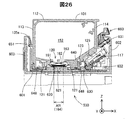
図23および図24は、キャリッジ520におけるホルダー部530の構成を示す概略斜視図である。図25は、ホルダー部530を上方から下方に向かって見たときの概略平面図である。図26は、図25のC−C切断におけるホルダー部530の概略断面図である。図26には、カートリッジ101が装着されている状態が図示されている。本実施形態では、ホルダー部530には、異なる色インクを収容する6種類のカートリッジ101が1つずつ装着される。より具体的には、ブラック、イエロ、マゼンタ、ライトマゼンタ、シアンおよびライトシアンの6色のインクを収容する6つのカートリッジ101が装着される。
23 and 24 are schematic perspective views showing the configuration of the
ホルダー部530は、矢印Zの方向が開口している略直方体形状の箱体として構成されており、5つの壁部601,602,603,604,605を有している(図23〜図25)。第1壁部601は、矢印Zの方向に向き、矢印X,Yの二方向に延在しており、ホルダー部530の底面を構成している。以下では、第1壁部601を底壁部601とも呼ぶ。
The
他の4つの壁部602〜605はそれぞれ、底壁部601に交差し、底壁部601から矢印Zの方向に延在しており、ホルダー部530の側面を構成している。ホルダー部530では、これら5つの壁部601〜605に囲まれている凹部によって、カートリッジ101が装着されるカートリッジ収容部610が構成されている。
Each of the other four
第2壁部602は、カートリッジ101の第4壁部114および第7壁部117と向かい合う。第3壁部603は、第2壁部602と矢印Xの方向において対向する位置にあり、カートリッジ101の第3壁部113と向かい合う。第4壁部604は、第2壁部602と第3壁部603とに交差しており、カートリッジ101の第5壁部115と向かい合う。第5壁部605は、第2壁部602と第3壁部603とに交差するとともに、矢印Yの方向において第4壁部604と対向する位置にあり、カートリッジ101の第6壁部116と向かい合う。
The
カートリッジ収容部610は、第4壁部604および第5壁部605に平行な複数の仕切り壁607によって、各カートリッジ101を受け入れ可能な複数の領域(スロット)に分割されている。仕切り壁607は、各スロットにカートリッジ101を挿入する際のガイドとして機能する。各スロットは、矢印Zの方向に開口しており、矢印Zの逆方向にカートリッジ101が差し込まれて装着される。各スロットには、インク導入部620と、電極部630と、突起部640と、リブ受入部650と、レバー660と、が1つずつ設けられている。
The cartridge
インク導入部620は、矢印Zの方向に開口する略楕円形状の開口部として構成されている(図24)。インク導入部620は、2つの隣り合う仕切り壁607に挟まれる位置に設けられている。ホルダー部530にカートリッジ101が装着されたときには、インク導入部620がインク供給部120のフィルター部161に接触する(図26)。カートリッジ101のインクは、インク導入部620を介して、ホルダー部530内に形成されている流路621に流入し、印刷ヘッド部540のインク室(図示は省略)へと供給される。
The
インク導入部620の周囲には、シール部622が設けられている(図25,図26)。シール部622は、例えば、弾性ゴムによって形成される。シール部622は、カートリッジ101が装着されたときに、カートリッジ101の外周壁部121の端面と接触して、インク導入部620を囲むシールラインを形成する。また、シール部622は、矢印Zの方向にカートリッジ101を付勢する。
A
電極部630は、第1壁部601と第2壁部602とが交差する角部に設けられており、斜め上方に向く端子面631を有し、その端子面631上に、複数の端子632が配列されている(図23)。電極部630の端子面631は、装着状態にあるカートリッジ101の第7壁部117とほぼ平行である(図26)。各端子632は、カートリッジ101の方向に突起しており、それぞれ、カートリッジ101の基板部125における対応するひとつの端子125tに電気的に接触する。各端子632は、プリンター500のフレキシブルケーブル517と電気的に接続されている。
The
突起部640は、インク導入部620と電極部630との間に設けられている(図24)。突起部640は、第1壁部601から矢印Zの方向に突起している。カートリッジ101がホルダー部530に装着されたときには、突起部640は、カートリッジ101の第1壁部111に設けられている凹部である位置決め部123内に収容される(図26)。突起部640は、位置決め部123に対応するサイズを有しており、位置決め部123に嵌合する。これによって、カートリッジ101はホルダー部530における配置位置や配置姿勢が規定される。
The
リブ受入部650は、第4壁部604の凹部として設けられている(図24)。リブ受入部650の開口形状は、カートリッジ101の第3壁部113に設けられているリブ部135の外周輪郭形状に対応しており、矢印Yの方向に延びる第1部位651と、矢印Zの方向に延びる第2部位652と、を有している。カートリッジ101がホルダー部530に装着されたときには、リブ部135の第1部位135aがリブ受入部650の第1部位651に嵌合し(図26)、リブ部135の第2部位135bがリブ受入部650の第2部位652に嵌合する(図示は省略)。
The
レバー660は、第2壁部602に設けられており、電極部630の上方に位置している。レバー660は、矢印Xの方向に回転移動可能なように設けられている。レバー660は、カートリッジ101が有する嵌合部137に対して矢印Zの逆方向に係合する。カートリッジ101の構成の説明において既に説明したように、レバー660は、装着が予定されているカートリッジ101の嵌合部137に嵌合可能な形状を有している。そのため、レバー660は、対応していない形状の嵌合部137を有するカートリッジ101には係合しない。
The
ホルダー部530にカートリッジ101が装着されるときには、まず、カートリッジ101のリブ部135の第2部位135bがリブ受入部650の第2部位652に挿入されて、第2部位652に沿って矢印Zの逆方向に移動する。そして、リブ部135の第1部位135aがリブ受入部650の第1部位651に係合する。その後、リブ部135の第1部位135aを支点として、カートリッジ101の第7壁部117側を下方に回転移動させて、突起部640を位置決め部123に嵌合させつつ、基板部125の各端子125tを電極部630の対応する端子632に接触させる。その上で、レバー660をカートリッジ101に向かって回転移動させて、カートリッジ101の嵌合部137に係合させる。
When the
カートリッジ101は、ホルダー部530において、第3壁部113のリブ部135の第1部位135aがリブ受入部650の第1部位651に係合し、第4壁部114の嵌合部137がレバー660に係合することによって、矢印Zの方向への移動が規制される。また、第3壁部113のリブ部135の第2部位135bがリブ受入部650の第2部位652に嵌合し、第1壁部111の位置決め部123に突起部640が嵌合することによって、矢印Xに沿った方向への移動が規制される。
In the
上述したように、本実施形態の保護キャップ付きカートリッジ100であれば、基板部125の接触部CPが保護キャップ102の第1係合部207および第2係合部208によって保護される。従って、電極部630に対する基板部125の電気的接触不良が抑制される。また、保護キャップ102の底壁部200によってキャリッジ520に装着される前に、位置決め部123に異物が入り込んでしまうことが抑制されるため、キャリッジ520に対するカートリッジ101の装着不良が抑制される。
As described above, in the case of the
その他に、インク供給部120の周囲に形成されている外周壁部121が保護キャップ102によって保護されるため、キャリッジ520に装着されたときのインク供給部120に対するシール性の低下が抑制される。また、保護キャップ102の操作部212が矢印Yの逆方向に突出していることによって、リブ部135が保護されるため、リブ部135の損傷によるキャリッジ520に対するカートリッジ101の装着不良が抑制される。
In addition, since the outer
[第1実施形態のまとめ]
以上のように、本実施形態の保護キャップ付きカートリッジ100であれば、保護キャップ102によって、カートリッジ101の基板部125における接触部CPをはじめとする各構成部が適切に保護される。また、カートリッジ101に対する保護キャップ102の装着時に、各係合部207,208,213,214の位置決めが容易化されている。さらに、各係合部207,208,213,214が、保護キャップ102をカートリッジ101に取り付ける際のガイドとしても機能するため、カートリッジ101に対する保護キャップ102の装着の際の利便性が高められている。また、保護キャップ102によって、カートリッジ101の位置決め部123への異物の混入が抑制される。保護キャップ付きカートリッジ100の外部にインクが漏洩してしまうことが抑制される。本実施形態の保護キャップ付きカートリッジ100であれば、各係合部207,208,213,214によって、カートリッジ101に対する保護キャップ102の装着後の安定性が高められている。その他にも、本実施形態における保護キャップ102およびそれを備える保護キャップ付きカートリッジ100であれば、上記実施形態において説明した種々の作用効果を奏することが可能である。
[Summary of the first embodiment]
As described above, in the case of the
B.第2実施形態:
図27は、本発明の第2実施形態における保護キャップ付きカートリッジ100Aの構成を示す概略正面図である。図27では、保護キャップ102の第1係合部207からシール部220の間の領域の状態を示すために、保護キャップ102の一部が概略断面によって図示されている。第2実施形態の保護キャップ付きカートリッジ100Aは、以下に説明する点以外は、第1実施形態の保護キャップ付きカートリッジ100とほぼ同じである。
B. Second embodiment:
FIG. 27 is a schematic front view showing the configuration of the
第2実施形態の保護キャップ付きカートリッジ100Aは、第1実施形態で説明したカートリッジ101に、第1実施形態で説明した保護キャップ102が装着されたものである。保護キャップ付きカートリッジ100Aでは、シール部220が矢印Zの逆方向に圧縮されることによって、カートリッジ101が保護キャップ102に対して矢印Zの逆方向に、より深く沈み込んでいる。これによって、4つの係合部207,208,213,214の各係合面207s,208s,213s,214sと、対応する被係合部131〜134の係合面131s〜134sと、が係合可能な状態なまま離間している。
In the
保護キャップ付きカートリッジ100Aでは、カートリッジ101の第1壁部111は、保護キャップ102の底壁部200に設けられている2つのリブ223,224の少なくとも一方に接触して支持されている。これによって、シール部220が過度に圧縮されてしまうことが抑制され、シール部220に付与される圧力が適切に維持される。従って、シール部220の劣化によるインク供給部120に対するシール性が低下してしまうことが抑制される。また、保護キャップ付きカートリッジ100Aでは、保護キャップ102の保護壁部210の上端面210sに、カートリッジ101の第3壁部113に設けられているリブ部135における第2部位135bの下端が接触している。これによって、シール部220に圧縮の負荷がかかることが、さらに抑制されている。
In the
以上のように、第2実施形態の保護キャップ付きカートリッジ100Aによれば、シール部220におけるシール性の低下が抑制されている。なお、第1実施形態の保護キャップ付きカートリッジ100も、保護キャップ102のリブ223,224や保護壁部210、カートリッジ101のリブ部135を有している。従って、第1実施形態の保護キャップ付きカートリッジ100も、シール部220におけるシール性の低下を抑制する効果を奏することが可能である。その他に、第2実施形態の保護キャップ付きカートリッジ100Aによれば、第1実施形態で説明したのと同様な種々の作用効果を奏することができる。
As described above, according to the
C.変形例:
C1.変形例1:
上記の各実施形態においては、保護キャップ102の各係合部207,208,213,214は凸部として構成されており、カートリッジ101の各被係合部131〜134は凹部として構成されている。これに対して、保護キャップ102の各係合部207,208,213,214およびカートリッジ101の各被係合部131〜134は、他の構成を有していてもよい。例えば、保護キャップ102の各係合部207,208,213,214が凹部として構成され、カートリッジ101の各被係合部131〜134が凸部として構成されてもよい。また、各係合部207,208,213,214と各被係合部131〜134とは係合面同士の面接触によって係合しなくてもよい。各係合部207,208,213,214と各被係合部131〜134とは、例えば、互いの線接触や点接触によって係合してもよい。
C. Modification:
C1. Modification 1:
In each of the above embodiments, the engaging
C2.変形例2:
上記の各実施形態において、第1係合部207が係合する第1被係合部131および第2係合部208が係合する第2被係合部132はそれぞれ、カートリッジ101の第7壁部117の下端に設けられている。これに対して、第1被係合部131および第2被係合部132は、カートリッジ101の第7壁部117の下端以外の位置に設けられていてもよい。第1被係合部131および第2被係合部132は、例えば、第7壁部117において、基板部125より上方の位置に設けられていてもよい。また、第1被係合部131および第2被係合部132は、カートリッジ101において第1壁部111からの高さ位置が同じでなくてもよく、異なる高さに設けられていてもよい。
C2. Modification 2:
In each of the above embodiments, the first engaged
C3.変形例3:
上記の各実施形態において、カートリッジ101の4つの被係合部131〜134は、第1壁部111の4つの角部に対応する位置に設けられている。これに対して、カートリッジ101の4つの被係合部131〜134は、第1壁部111の4つの角部に対応する位置に設けられていなくてもよい。例えば、各被係合部131〜134は、角部から離間した位置にもうけられていてもよい。また、4つの被係合部131〜134はそれぞれ、第1壁部111に対して異なる高さ位置に設けられていてもよい。
C3. Modification 3:
In each of the above embodiments, the four engaged
C4.変形例4:
上記各実施形態では、保護キャップ102は、4つの係合部207,208,213,214を有している。これに対して、保護キャップ102は、第7壁部117側に、第1係合部207,208を有し、第3壁部113側に1つの係合部のみが設けられている構成であってもよい。
C4. Modification 4:
In each of the above embodiments, the
C5.変形例5:
上記の各実施形態において、プリンター500の電極部630と電気的に接触する接触部CPは、基板部125の端子125t上に形成されている。これに対して、接触部CPは、基板部125の端子125t上において形成されていなくてもよく、例えば、カートリッジ101の壁面に直接的に設けられた端子上に形成されてもよい。
C5. Modification 5:
In each of the above embodiments, the contact portion CP that electrically contacts the
C6.変形例6:
上記の各実施形態において、カートリッジ101の位置決め部123は凹部として構成されている。これに対して、位置決め部123は凹部以外の構成を有していてもよく、例えば、凸部として構成されていてもよい。
C6. Modification 6:
In each of the above embodiments, the
C7.変形例7:
上記の各実施形態において、プリンター500のキャリッジ520に装着されたときのカートリッジ101の配置位置や配置姿勢を規制する規制部であるリブ部135や嵌合部137は、カートリッジ101の壁面から突起している凸構造として構成されている。これに対して、そうした規制部は、凸構造以外の構成を有していてもよく、例えば、凹部やスリットなどによって構成されてもよい。規制部は、キャリッジに設けられている被嵌合部に対応する形状を有するように構成されていればよい。
C7. Modification 7:
In each of the above embodiments, the
C8.変形例8:
上記の各実施形態において、カートリッジ101は、7つの壁部111〜117を有している。これに対して、カートリッジ101は、7つの壁部111〜117を有していなくてもよく、例えば、6つの壁部111〜116を有する略直方体形状によって構成されていてもよい。その他に、カートリッジ101は、円柱形状や、略三角錐形状を有していてもよい。
C8. Modification 8:
In each of the above embodiments, the
C9.変形例9:
上記の各実施形態において、カートリッジ101は、インク供給部120の周りに外周壁部121を有している。これに対して、外周壁部121は省略されてもよい。
C9. Modification 9:
In each of the above embodiments, the
C10.変形例10:
上記実施形態では、カートリッジ101は半密閉型のインクカートリッジとして構成されている。これに対して、カートリッジ101は半密閉型のインクカートリッジとして構成されていなくてもよく、例えば、インクの消費にともなって、随時、外部の空気が取り込まれる構成のインクカートリッジとして構成されていてもよい。
C10. Modification 10:
In the above embodiment, the
C11.変形例11:
上記各実施形態のカートリッジ101は、プリンター500とは異なる構成のプリンターに装着されてもよい。上記のプリンター500は、主走査方向に往復移動するキャリッジ520上のホルダー60にカートリッジ101が装着される、いわゆるオンキャリッジタイプである。これに対して、カートリッジ101は、いわゆるオフキャリッジタイプのプリンターに搭載されてもよい。オフキャリッジタイプのプリンターでは、カートリッジ101は、キャリッジから離間して設けられた不動のホルダーに装着され、ホルダーに接続されているフレキシブルチューブを介して、キャリッジが有する印刷ヘッド部にインクを供給する。
C11. Modification 11:
The
本発明は、上述の実施形態や実施例、変形例に限られるものではなく、その趣旨を逸脱しない範囲において種々の構成で実現することができる。本発明は、例えば、プリンターに供給されるインク以外の液体を収容する液体収容容器において実現されてもよい。また、発明の概要の欄に記載した各形態中の技術的特徴に対応する実施形態、実施例、変形例中の技術的特徴は、上述の課題の一部又は全部を解決するために、あるいは、上述の効果の一部又は全部を達成するために、適宜、差し替えや、組み合わせを行うことも可能である。また、その技術的特徴が本明細書中に必須なものとして説明されていなければ、適宜、削除することが可能である。 The present invention is not limited to the above-described embodiments, examples, and modifications, and can be realized with various configurations within a range not deviating from the gist thereof. The present invention may be realized, for example, in a liquid storage container that holds a liquid other than ink supplied to a printer. In addition, the technical features in the embodiments, examples, and modifications corresponding to the technical features in each embodiment described in the column of the outline of the invention are used to solve some or all of the above-mentioned problems, or , It is also possible to replace or combine as appropriate in order to achieve a part or all of the above-mentioned effects. If the technical features are not described as essential in the present specification, they can be deleted as appropriate.
100…保護キャップ付きカートリッジ、101…カートリッジ、102…保護キャップ、103…土台部、111〜117…壁部、120…インク供給部、121…外周壁部、122…連通口、123…位置決め部、125…基板部、125s…記憶装置、125t…端子、131〜134…被係合部、131s〜134s…係合面、135…リブ部、135a…第1部位、135b…第2部位、137…嵌合部、140…通気部、141…通気孔、142…通気溝、143…外周凹部、144…凸壁部、145…シール、150…本体部材、151…蓋部材、152…インク収容部、153…シート部材、153b…本体部、153f…外周縁部、153h…貫通孔、155…圧力調整機構、156…受圧板、157…付勢部材、160…開口部、161…フィルター部、162…フォーム部、163…板バネ部、164…インク供給口、166…連通路、170…空気室、171…大気弁、173…弁座、173c…凹部、173t…開口端面、174…空気導入口、175…弁部材、176…弁体部、177…レバー部、178…コイルばね、200…底壁部、201〜204…側壁部、205…基板側係合部、206…レバー式係合部、207…第1係合部、207t…突起部、207s…係合面、208…第2係合部、208t…突起部、208s…係合面、210…保護壁部、211…連結部、212…操作部、213…第3係合部、213s…係合面、214…第4係合部、214s…係合面、220…シール部、221…枠状部位、222…仕切壁部、223,224…リブ、300…梱包部材、500…プリンター、510…制御部、517…フレキシブルケーブル、520…キャリッジ、530…ホルダー部、540…印刷ヘッド部、601〜605…壁部、607…仕切り壁、610…カートリッジ収容部、620…インク導入部、621…流路、622…シール部、630…電極部、631…端子面、632…端子、640…突起部、650…リブ受入部、651…第1部位、652…第2部位、660…レバー 100 ... Cartridge with protective cap, 101 ... Cartridge, 102 ... Protective cap, 103 ... Base part, 111-117 ... Wall part, 120 ... Ink supply part, 121 ... Outer wall part, 122 ... Communication port, 123 ... Positioning part, 125 ... Substrate, 125s ... Storage device, 125t ... Terminal, 131-134 ... Engaged part, 131s-134s ... Engaging surface, 135 ... Rib part, 135a ... First part, 135b ... Second part, 137 ... Fitting part, 140 ... Ventilation part, 141 ... Vent hole, 142 ... Ventilation groove, 143 ... Outer peripheral recess, 144 ... Convex wall part, 145 ... Seal, 150 ... Main body member, 151 ... Lid member, 152 ... Ink storage part, 153 ... Sheet member, 153b ... Main body, 153f ... Outer peripheral edge, 153h ... Through hole, 155 ... Pressure adjustment mechanism, 156 ... Pressure receiving plate, 157 ... Biasing member, 160 ... Opening, 161 ... Filter part, 162 ... Foam part, 163 ... Leaf spring part, 164 ... Ink supply port, 166 ... Communication passage, 170 ... Air chamber, 171 ... Atmospheric valve, 173 ... Valve seat, 173c ... Recession, 173t ... Open end face, 174 ... Air inlet, 175 ... Valve member, 176 ... Valve body part, 177 ... Lever part, 178 ... Coil spring, 200 ... Bottom wall part, 201-204 ... Side wall part, 205 ... Board side engaging part, 206 ... Lever type engaging part, 207 ... 1st engaging part, 207t ... protruding part, 207s ... engaging surface, 208 ... second engaging part, 208t ... protruding part, 208s ... engaging surface, 210 ... protective wall part, 211 ... connecting part, 212 ... Operation part, 213 ... Third engaging part, 213s ... Engaging surface, 214 ... Fourth engaging part, 214s ... Engaging surface, 220 ... Sealing part, 221 ... Frame-shaped part, 222 ... Partition wall part, 223 , 224 ... Ribs, 300 ... Packing members, 500 ... Printers, 510 ... Control units, 517 ... Flexible cables, 520 ... Carriage, 530 ... Holders, 540 ... Printing heads, 601-605 ... Walls, 607 ... Partition walls , 610 ... Cartridge accommodating part, 620 ... Ink introduction part, 621 ... Flow path, 622 ... Seal part, 630 ... Electrode part, 631 ... Terminal surface, 632 ... Terminal, 640 ... Protrusion part, 650 ... Rib receiving part, 651 ... 1st part, 652 ... 2nd part, 660 ... Lever
Claims (12)
液体噴射装置に液体を供給する液体収容体と、
前記液体収容体に装着される保護部材と、
を備え、
前記液体収容体は、
第1壁部と、
前記第1壁部に対向する第2壁部と、
前記第1壁部と前記第2壁部とに交差する第3壁部と、
前記第1壁部と前記第2壁部とに交差し、前記第3壁部と対向する第4壁部と、
前記第1壁部と前記第2壁部と前記第3壁部と前記第4壁部とに交差する第5壁部と、
前記第1壁部と前記第2壁部と前記第3壁部と前記第4壁部とに交差し、前記第5壁部と対向する第6壁部と、
前記第1壁部と前記第2壁部と前記第5壁部と前記第6壁部とに交差し、前記第1壁部と前記第4壁部との間に位置する第7壁部と、
前記液体が通過する液体供給口と、
前記液体噴射装置が備える電極部に接触する複数の接触部と、
前記保護部材が係合する第1被係合部および第2被係合部と、
を含み、
前記液体供給口と、前記第1被係合部と、前記第2被係合部とは、前記第1壁部に設けられており、
前記複数の接触部は、前記第7壁部に設けられており、
前記保護部材は、
前記液体供給口に対向するシール部と、
前記第1被係合部に係合する第1係合部と、
前記第2被係合部に係合する第2係合部と、
を含み、
前記シール部が前記液体供給口に対向する方向を第1方向とし、前記第1方向に直交し、前記液体供給口から前記複数の接触部に向かう方向を第2方向とし、前記第1方向と前記第2方向とに直交する方向を第3方向とするときに、
前記第1方向に沿って見たときに、前記複数の接触部は、前記第3方向において、前記第1係合部と前記第2係合部との間に位置しており、
前記第1被係合部と前記第2被係合部とは、前記第1壁部と前記第7壁部とが交差している角部に形成されており、
前記第3方向における前記第1係合部と前記第2係合部との間の距離は、前記第3方向における前記複数の接触部の間の最大距離よりも大きく、
前記第3方向における前記第1係合部と前記第2係合部との間の距離と、前記第3方向における前記複数の接触部の間の最大距離との間の差は、前記第3方向における前記第1被係合部の幅よりも小さい、液体収容容器。 It is a liquid storage container
A liquid container that supplies liquid to the liquid injector,
A protective member attached to the liquid container and
With
The liquid container is
The first wall and
The second wall portion facing the first wall portion and
A third wall portion that intersects the first wall portion and the second wall portion,
A fourth wall portion that intersects the first wall portion and the second wall portion and faces the third wall portion.
A fifth wall portion that intersects the first wall portion, the second wall portion, the third wall portion, and the fourth wall portion, and
A sixth wall portion that intersects the first wall portion, the second wall portion, the third wall portion, and the fourth wall portion, and faces the fifth wall portion.
A seventh wall portion that intersects the first wall portion, the second wall portion, the fifth wall portion, and the sixth wall portion, and is located between the first wall portion and the fourth wall portion. ,
The liquid supply port through which the liquid passes and
A plurality of contact portions in contact with the electrode portion included in the liquid injection device, and
The first engaged portion and the second engaged portion with which the protective member engages,
Including
The liquid supply port, the first engaged portion, and the second engaged portion are provided on the first wall portion.
The plurality of contact portions are provided on the seventh wall portion, and the plurality of contact portions are provided on the seventh wall portion.
The protective member is
The seal portion facing the liquid supply port and
The first engaging portion that engages with the first engaged portion and
A second engaging portion that engages with the second engaged portion and
Including
The direction in which the seal portion faces the liquid supply port is the first direction, orthogonal to the first direction, and the direction from the liquid supply port toward the plurality of contact portions is the second direction, which is the same as the first direction. When the direction orthogonal to the second direction is the third direction,
When viewed along the first direction, the plurality of contact portions are located between the first engaging portion and the second engaging portion in the third direction.
The first engaged portion and the second engaged portion are formed at a corner portion where the first wall portion and the seventh wall portion intersect .
The distance between the first engaging portion and the second engaging portion in the third direction is larger than the maximum distance between the plurality of contact portions in the third direction.
The difference between the distance between the first engaging portion and the second engaging portion in the third direction and the maximum distance between the plurality of contact portions in the third direction is the third. A liquid container that is smaller than the width of the first engaged portion in the direction .
前記液体収容体は、前記複数の接触部が配置された基板を含み、
前記第1方向に沿って見たときに、前記基板は、前記第3方向において、前記第1係合部と前記第2係合部との間に位置している、液体収容容器。 The liquid storage container according to claim 1.
The liquid container includes a substrate on which the plurality of contact portions are arranged.
A liquid container in which the substrate is located between the first engaging portion and the second engaging portion in the third direction when viewed along the first direction.
前記液体収容体は、さらに、前記液体噴射装置に装着されるときの配置位置を規定する位置決め部を含み、
前記位置決め部は、前記第2方向において、前記液体供給口と前記複数の接触部との間に位置し、かつ、前記液体供給口と前記第1被係合部および前記第2被係合部との間に位置しており、前記保護部材の一部に覆われている、液体収容容器。 The liquid storage container according to claim 1 or 2 .
The liquid container further includes a positioning unit that defines a placement position when mounted on the liquid injection device.
The positioning portion is located between the liquid supply port and the plurality of contact portions in the second direction, and the liquid supply port, the first engaged portion, and the second engaged portion. A liquid container located between and covered with a part of the protective member.
液体噴射装置に液体を供給する液体収容体と、
前記液体収容体に装着される保護部材と、
を備え、
前記液体収容体は、
第1壁部と、
前記第1壁部に対向する第2壁部と、
前記第1壁部と前記第2壁部とに交差する第3壁部と、
前記第1壁部と前記第2壁部とに交差し、前記第3壁部と対向する第4壁部と、
前記第1壁部と前記第2壁部と前記第3壁部と前記第4壁部とに交差する第5壁部と、
前記第1壁部と前記第2壁部と前記第3壁部と前記第4壁部とに交差し、前記第5壁部と対向する第6壁部と、
前記第1壁部と前記第2壁部と前記第5壁部と前記第6壁部とに交差し、前記第1壁部と前記第4壁部との間に位置する第7壁部と、
前記液体が通過する液体供給口と、
前記液体噴射装置が備える電極部に接触する複数の接触部と、
前記保護部材が係合する第1被係合部および第2被係合部と、
を含み、
前記液体供給口と、前記第1被係合部と、前記第2被係合部とは、前記第1壁部に設けられており、
前記複数の接触部は、前記第7壁部に設けられており、
前記保護部材は、
前記液体供給口に対向するシール部と、
前記第1被係合部に係合する第1係合部と、
前記第2被係合部に係合する第2係合部と、
を含み、
前記シール部が前記液体供給口に対向する方向を第1方向とし、前記第1方向に直交し、前記液体供給口から前記複数の接触部に向かう方向を第2方向とし、前記第1方向と前記第2方向とに直交する方向を第3方向とするときに、
前記第1方向に沿って見たときに、前記複数の接触部は、前記第3方向において、前記第1係合部と前記第2係合部との間に位置しており、
前記第1被係合部と前記第2被係合部とは、前記第1壁部と前記第7壁部とが交差している角部に形成されており、
前記液体収容体は、さらに、
前記液体噴射装置の被嵌合部に対応する形状を有し、前記被嵌合部に嵌合する嵌合部と、
前記保護部材に係合する第3被係合部および第4被係合部と、
を含み、
前記保護部材は、さらに、
前記第3被係合部に係合する第3係合部と、
前記第4被係合部に係合する第4係合部と、
を含み、
前記第1方向に沿って見たときに、
前記液体供給口は、前記第2方向において、前記複数の接触部と前記嵌合部との間に位置しており、
前記嵌合部は、前記第3方向において、前記第3係合部と前記第4係合部との間に位置している、液体収容容器。 It is a liquid storage container
A liquid container that supplies liquid to the liquid injector,
A protective member attached to the liquid container and
With
The liquid container is
The first wall and
The second wall portion facing the first wall portion and
A third wall portion that intersects the first wall portion and the second wall portion,
A fourth wall portion that intersects the first wall portion and the second wall portion and faces the third wall portion.
A fifth wall portion that intersects the first wall portion, the second wall portion, the third wall portion, and the fourth wall portion, and
A sixth wall portion that intersects the first wall portion, the second wall portion, the third wall portion, and the fourth wall portion, and faces the fifth wall portion.
A seventh wall portion that intersects the first wall portion, the second wall portion, the fifth wall portion, and the sixth wall portion, and is located between the first wall portion and the fourth wall portion. ,
The liquid supply port through which the liquid passes and
A plurality of contact portions in contact with the electrode portion included in the liquid injection device, and
The first engaged portion and the second engaged portion with which the protective member engages,
Including
The liquid supply port, the first engaged portion, and the second engaged portion are provided on the first wall portion.
The plurality of contact portions are provided on the seventh wall portion, and the plurality of contact portions are provided on the seventh wall portion.
The protective member is
The seal portion facing the liquid supply port and
The first engaging portion that engages with the first engaged portion and
A second engaging portion that engages with the second engaged portion and
Including
The direction in which the seal portion faces the liquid supply port is defined as the first direction, orthogonal to the first direction, and the direction from the liquid supply port toward the plurality of contact portions is defined as the second direction, which is the same as the first direction. When the direction orthogonal to the second direction is the third direction,
When viewed along the first direction, the plurality of contact portions are located between the first engaging portion and the second engaging portion in the third direction.
The first engaged portion and the second engaged portion are formed at a corner portion where the first wall portion and the seventh wall portion intersect.
The liquid container further
A fitting portion having a shape corresponding to the fitted portion of the liquid injection device and fitting to the fitted portion,
A third engaged portion and a fourth engaged portion that engage with the protective member,
Including
The protective member further
A third engaging portion that engages with the third engaged portion and
A fourth engaging portion that engages with the fourth engaged portion and
Including
When viewed along the first direction,
The liquid supply port is located between the plurality of contact portions and the fitting portion in the second direction.
The fitting portion is a liquid storage container located between the third engaging portion and the fourth engaging portion in the third direction.
液体噴射装置に液体を供給する液体収容体と、
前記液体収容体に装着される保護部材と、
を備え、
前記液体収容体は、
第1壁部と、
前記第1壁部に対向する第2壁部と、
前記第1壁部と前記第2壁部とに交差する第3壁部と、
前記第1壁部と前記第2壁部とに交差し、前記第3壁部と対向する第4壁部と、
前記第1壁部と前記第2壁部と前記第3壁部と前記第4壁部とに交差する第5壁部と、
前記第1壁部と前記第2壁部と前記第3壁部と前記第4壁部とに交差し、前記第5壁部と対向する第6壁部と、
前記第1壁部と前記第2壁部と前記第5壁部と前記第6壁部とに交差し、前記第1壁部と前記第4壁部との間に位置する第7壁部と、
前記液体が通過する液体供給口と、
前記液体噴射装置が備える電極部に接触する複数の接触部と、
前記保護部材が係合する第1被係合部および第2被係合部と、
を含み、
前記液体供給口と、前記第1被係合部と、前記第2被係合部とは、前記第1壁部に設けられており、
前記複数の接触部は、前記第7壁部に設けられており、
前記保護部材は、
前記液体供給口に対向するシール部と、
前記第1被係合部に係合する第1係合部と、
前記第2被係合部に係合する第2係合部と、
を含み、
前記シール部が前記液体供給口に対向する方向を第1方向とし、前記第1方向に直交し、前記液体供給口から前記複数の接触部に向かう方向を第2方向とし、前記第1方向と前記第2方向とに直交する方向を第3方向とするときに、
前記第1方向に沿って見たときに、前記複数の接触部は、前記第3方向において、前記第1係合部と前記第2係合部との間に位置しており、
前記第1被係合部と前記第2被係合部とは、前記第1壁部と前記第7壁部とが交差している角部に形成されており、
前記第3壁部には、リブが設けられており、
前記リブは、前記第3方向に沿って延びる第1部分と、前記第1部分から前記第1壁部に向かって延びる第2部分と、を有し、
前記保護部材は、
前記第1壁部に対向する本体部と、
前記本体部に接続されている可動部と、
を含み、
前記シール部と、前記第1係合部と前記第2係合部とは、前記本体部に設けられており、
前記可動部には、前記保護部材を前記液体収容体から取り外す際に利用される操作部が設けられており、
前記可動部の一部が、前記第2部分と前記第1方向に当接している、液体収容容器。 It is a liquid storage container
A liquid container that supplies liquid to the liquid injector,
A protective member attached to the liquid container and
With
The liquid container is
The first wall and
The second wall portion facing the first wall portion and
A third wall portion that intersects the first wall portion and the second wall portion,
A fourth wall portion that intersects the first wall portion and the second wall portion and faces the third wall portion.
A fifth wall portion that intersects the first wall portion, the second wall portion, the third wall portion, and the fourth wall portion, and
A sixth wall portion that intersects the first wall portion, the second wall portion, the third wall portion, and the fourth wall portion, and faces the fifth wall portion.
A seventh wall portion that intersects the first wall portion, the second wall portion, the fifth wall portion, and the sixth wall portion, and is located between the first wall portion and the fourth wall portion. ,
The liquid supply port through which the liquid passes and
A plurality of contact portions in contact with the electrode portion included in the liquid injection device, and
The first engaged portion and the second engaged portion with which the protective member engages,
Including
The liquid supply port, the first engaged portion, and the second engaged portion are provided on the first wall portion.
The plurality of contact portions are provided on the seventh wall portion, and the plurality of contact portions are provided on the seventh wall portion.
The protective member is
The seal portion facing the liquid supply port and
The first engaging portion that engages with the first engaged portion and
A second engaging portion that engages with the second engaged portion and
Including
The direction in which the seal portion faces the liquid supply port is defined as the first direction, orthogonal to the first direction, and the direction from the liquid supply port toward the plurality of contact portions is defined as the second direction, which is the same as the first direction. When the direction orthogonal to the second direction is the third direction,
When viewed along the first direction, the plurality of contact portions are located between the first engaging portion and the second engaging portion in the third direction.
The first engaged portion and the second engaged portion are formed at a corner portion where the first wall portion and the seventh wall portion intersect.
Ribs are provided on the third wall portion.
The rib has a first portion extending along the third direction and a second portion extending from the first portion toward the first wall portion.
The protective member is
The main body facing the first wall and
The movable part connected to the main body and
Including
The seal portion, the first engaging portion, and the second engaging portion are provided on the main body portion.
The movable portion is provided with an operation portion used when removing the protective member from the liquid container.
A liquid storage container in which a part of the movable portion is in contact with the second portion in the first direction.
液体噴射装置に液体を供給する液体収容体と、
前記液体収容体に装着される保護部材と、
を備え、
前記液体収容体は、
前記液体が通過する液体供給口と、
前記液体噴射装置が備える電極部に接触する複数の接触部と、
前記液体噴射装置に装着されるときの配置位置を規定する位置決め部と、
前記保護部材が係合する第1被係合部および第2被係合部と、
を含み、
前記保護部材は、
前記液体供給口に対向するシール部と、
前記第1被係合部に係合する第1係合部と、
前記第2被係合部に係合する第2係合部と、
を含み、
前記シール部が前記液体供給口に対向する方向を第1方向とし、前記第1方向に直交し、前記液体供給口から前記複数の接触部に向かう方向を第2方向とし、前記第1方向と前記第2方向とに直交する方向を第3方向とするときに、
前記位置決め部は、前記第2方向において、前記液体供給口と前記複数の接触部との間に位置し、かつ、前記液体供給口と前記第1被係合部および前記第2被係合部との間に位置しており、前記保護部材の一部に覆われている、液体収容容器。 It is a liquid storage container
A liquid container that supplies liquid to the liquid injector,
A protective member attached to the liquid container and
With
The liquid container is
The liquid supply port through which the liquid passes and
A plurality of contact portions in contact with the electrode portion included in the liquid injection device, and
A positioning unit that defines the placement position when mounted on the liquid injection device,
The first engaged portion and the second engaged portion with which the protective member engages,
Including
The protective member is
The seal portion facing the liquid supply port and
The first engaging portion that engages with the first engaged portion and
A second engaging portion that engages with the second engaged portion and
Including
The direction in which the seal portion faces the liquid supply port is the first direction, orthogonal to the first direction, and the direction from the liquid supply port toward the plurality of contact portions is the second direction, which is the same as the first direction. When the direction orthogonal to the second direction is the third direction,
The positioning portion is located between the liquid supply port and the plurality of contact portions in the second direction, and the liquid supply port, the first engaged portion, and the second engaged portion. A liquid container located between and covered with a part of the protective member.
液体噴射装置に液体を供給する液体収容体と、
前記液体収容体に装着される保護部材と、
を備え、
前記液体収容体は、
前記液体が通過する液体供給口と、
前記液体噴射装置が備える電極部に接触する複数の接触部と、
前記液体噴射装置の被嵌合部に対応する形状を有し、前記被嵌合部に嵌合する嵌合部と、
前記保護部材が係合する一対の被係合部と、
を含み、
前記保護部材は、
前記液体供給口に対向するシール部と、
前記一対の被係合部のそれぞれに係合する係合部の組である一対の係合部と、
を含み、
前記シール部が前記液体供給口に対向する方向を第1方向とし、前記第1方向に直交し、前記液体供給口から前記複数の接触部に向かう方向を第2方向とし、前記第1方向と前記第2方向とに直交する方向を第3方向とするときに、
前記第1方向に沿って見たときに、
前記液体供給口は、前記第2方向において、前記複数の接触部と前記嵌合部との間に位置しており、
前記嵌合部は、前記第3方向において、前記一対の係合部のそれぞれの間に位置している、液体収容容器。 It is a liquid storage container
A liquid container that supplies liquid to the liquid injector,
A protective member attached to the liquid container and
With
The liquid container is
The liquid supply port through which the liquid passes and
A plurality of contact portions in contact with the electrode portion included in the liquid injection device, and
A fitting portion having a shape corresponding to the fitted portion of the liquid injection device and fitting to the fitted portion,
A pair of engaged portions with which the protective member engages,
Including
The protective member is
The seal portion facing the liquid supply port and
A pair of engaging portions, which is a set of engaging portions that engage with each of the pair of engaged portions,
Including
The direction in which the seal portion faces the liquid supply port is the first direction, orthogonal to the first direction, and the direction from the liquid supply port toward the plurality of contact portions is the second direction, which is the same as the first direction. When the direction orthogonal to the second direction is the third direction,
When viewed along the first direction,
The liquid supply port is located between the plurality of contact portions and the fitting portion in the second direction.
The fitting portion is a liquid storage container located between the pair of engaging portions in the third direction.
前記一対の係合部はそれぞれ、前記第3方向において前記液体収容体に向かって突出する凸形状を有し、前記保護部材を前記液体収容体に装着する過程において、前記一対の被係合部に接触する前に、前記液体収容体に当接する、液体収容容器。 The liquid storage container according to claim 7 .
Each of the pair of engaging portions has a convex shape protruding toward the liquid container in the third direction, and in the process of mounting the protective member on the liquid container, the pair of engaged portions are engaged. A liquid container that comes into contact with the liquid container before contacting the liquid container.
液体噴射装置に液体を供給する液体収容体と、
前記液体収容体に装着される保護部材と、
を備え、
前記液体収容体は、
第1壁部と、
前記第1壁部に対向する第2壁部と、
前記第1壁部と前記第2壁部とに交差する第3壁部と、
前記第1壁部と前記第2壁部とに交差し、前記第3壁部と対向する第4壁部と、
前記第1壁部と前記第2壁部と前記第3壁部と前記第4壁部とに交差する第5壁部と、
前記第1壁部と前記第2壁部と前記第3壁部と前記第4壁部とに交差し、前記第5壁部と対向する第6壁部と、
前記第1壁部と前記第2壁部と前記第5壁部と前記第6壁部とに交差し、前記第1壁部と前記第4壁部との間に位置する第7壁部と、
前記液体が通過する液体供給口と、
前記液体噴射装置が備える電極部に接触する複数の接触部と、
前記保護部材が係合する第1被係合部および第2被係合部と、
を含み、
前記液体供給口と、前記第1被係合部と、前記第2被係合部とは、前記第1壁部に設けられており、
前記複数の接触部は、前記第7壁部に設けられており、
前記保護部材は、
前記液体供給口に対向するシール部と、
前記第1被係合部に係合する第1係合部と、
前記第2被係合部に係合する第2係合部と、
を含み、
前記シール部が前記液体供給口に対向する方向を第1方向とし、前記第1方向に直交し、前記液体供給口から前記複数の接触部に向かう方向を第2方向とし、前記第1方向と前記第2方向とに直交する方向を第3方向とするときに、
前記第1方向に沿って見たときに、前記複数の接触部は、前記第3方向において、前記第1係合部と前記第2係合部との間に位置しており、
前記第1被係合部と前記第2被係合部とは、前記第1壁部と前記第7壁部とが交差している角部に形成されており、
前記液体収容体は、前記第1方向に沿って見たときに、前記液体供給口を囲む外周壁部を有しており、
前記外周壁部は、前記シール部と前記第1方向において接触する、液体収容容器。 It is a liquid storage container
A liquid container that supplies liquid to the liquid injector,
A protective member attached to the liquid container and
With
The liquid container is
The first wall and
The second wall portion facing the first wall portion and
A third wall portion that intersects the first wall portion and the second wall portion,
A fourth wall portion that intersects the first wall portion and the second wall portion and faces the third wall portion.
A fifth wall portion that intersects the first wall portion, the second wall portion, the third wall portion, and the fourth wall portion, and
A sixth wall portion that intersects the first wall portion, the second wall portion, the third wall portion, and the fourth wall portion, and faces the fifth wall portion.
A seventh wall portion that intersects the first wall portion, the second wall portion, the fifth wall portion, and the sixth wall portion, and is located between the first wall portion and the fourth wall portion. ,
The liquid supply port through which the liquid passes and
A plurality of contact portions in contact with the electrode portion included in the liquid injection device, and
The first engaged portion and the second engaged portion with which the protective member engages,
Including
The liquid supply port, the first engaged portion, and the second engaged portion are provided on the first wall portion.
The plurality of contact portions are provided on the seventh wall portion, and the plurality of contact portions are provided on the seventh wall portion.
The protective member is
The seal portion facing the liquid supply port and
The first engaging portion that engages with the first engaged portion and
A second engaging portion that engages with the second engaged portion and
Including
The direction in which the seal portion faces the liquid supply port is defined as the first direction, orthogonal to the first direction, and the direction from the liquid supply port toward the plurality of contact portions is defined as the second direction, which is the same as the first direction. When the direction orthogonal to the second direction is the third direction,
When viewed along the first direction, the plurality of contact portions are located between the first engaging portion and the second engaging portion in the third direction.
The first engaged portion and the second engaged portion are formed at a corner portion where the first wall portion and the seventh wall portion intersect.
The liquid container has an outer peripheral wall portion surrounding the liquid supply port when viewed along the first direction.
The outer peripheral wall portion is a liquid storage container that comes into contact with the seal portion in the first direction.
液体噴射装置に液体を供給する液体収容体と、
前記液体収容体に装着される保護部材と、
を備え、
前記液体収容体は、
前記液体が通過する液体供給口と、
前記液体噴射装置が備える電極部に接触する複数の接触部と、
前記保護部材が係合する第1被係合部と、
前記保護部材が係合する第2被係合部と、
前記保護部材が係合する第3被係合部と、
前記保護部材が係合する第4被係合部と、
を含み、
前記保護部材は、
前記液体供給口に対向するシール部と、
前記第1被係合部に係合する第1係合部と、
前記第2被係合部に係合する第2係合部と、
前記第3被係合部に係合する第3係合部と、
前記第4被係合部に係合する第4係合部と、
を含み、
前記シール部が前記液体供給口に対向する方向である第1方向に沿って見たときに、前記液体供給口は、前記第1係合部と前記第2係合部と前記第3係合部と前記第4係合部とに囲まれている領域内に位置しており、
前記液体収容体は、前記第1方向に沿って見たときに、前記液体供給口を囲む外周壁部を有しており、
前記外周壁部は、前記シール部と前記第1方向において接触する、液体収容容器。 It is a liquid storage container
A liquid container that supplies liquid to the liquid injector,
A protective member attached to the liquid container and
With
The liquid container is
The liquid supply port through which the liquid passes and
A plurality of contact portions in contact with the electrode portion included in the liquid injection device, and
With the first engaged portion with which the protective member engages,
With the second engaged portion with which the protective member engages,
With the third engaged portion with which the protective member engages,
With the fourth engaged portion with which the protective member engages,
Including
The protective member is
The seal portion facing the liquid supply port and
The first engaging portion that engages with the first engaged portion and
A second engaging portion that engages with the second engaged portion and
A third engaging portion that engages with the third engaged portion and
A fourth engaging portion that engages with the fourth engaged portion and
Including
When the seal portion is viewed along the first direction, which is the direction facing the liquid supply port, the liquid supply port is the first engaging portion, the second engaging portion, and the third engaging portion. It is located in the area surrounded by the portion and the fourth engaging portion.
The liquid container has an outer peripheral wall portion surrounding the liquid supply port when viewed along the first direction.
The outer peripheral wall portion is a liquid storage container that comes into contact with the seal portion in the first direction.
前記液体供給口に対向するシール部と、
前記液体収容体が有する第1被係合部に係合する第1係合部と、
前記液体収容体が有する第2被係合部に係合する第2係合部と、
を含み、
前記保護部材が前記液体収容体に装着された状態において、前記シール部が前記液体供給口に対向する方向を第1方向とし、前記第1方向に直交し、前記液体供給口から前記複数の接触部に向かう方向を第2方向とし、前記第1方向と前記第2方向とに直交する方向を第3方向とするときに、
前記第1方向に沿って見たときに、前記複数の接触部は、前記第3方向において、前記第1係合部と前記第2係合部との間に位置しており、
前記液体収容体は、前記複数の接触部が配置された基板を含み、
前記第3方向における前記第1係合部と前記第2係合部との間の距離は、前記第3方向における前記基板の幅よりも大きく、
前記第3方向における前記第1係合部と前記第2係合部の間の距離と、前記第3方向における前記基板の幅との差は、前記第3方向における前記第1被係合部の幅より小さい、保護部材。 A protective member attached to a liquid container including a liquid supply port through which a liquid passes and a plurality of contact portions in contact with an electrode portion included in the liquid injection device.
The seal portion facing the liquid supply port and
A first engaging portion that engages with the first engaged portion of the liquid container,
A second engaging portion that engages with the second engaged portion of the liquid container,
Including
In a state where the protective member is attached to the liquid container, the direction in which the seal portion faces the liquid supply port is the first direction, orthogonal to the first direction, and the plurality of contacts from the liquid supply port. When the direction toward the portion is the second direction and the direction orthogonal to the first direction and the second direction is the third direction,
When viewed along the first direction, the plurality of contact portions are located between the first engaging portion and the second engaging portion in the third direction.
The liquid container includes a substrate on which the plurality of contact portions are arranged.
The distance between the first engaging portion and the second engaging portion in the third direction is larger than the width of the substrate in the third direction.
The difference between the distance between the first engaging portion and the second engaging portion in the third direction and the width of the substrate in the third direction is the first engaged portion in the third direction. Protective material smaller than the width of.
前記液体収容体は、さらに、前記液体噴射装置の被嵌合部に対応する形状を有し、前記被嵌合部に嵌合する嵌合部と、前記保護部材に係合する第3被係合部および第4被係合部と、を含み、
前記保護部材は、さらに、
前記第3被係合部に係合する第3係合部と、
前記第4被係合部に係合する第4係合部と、
を含み、
前記第1方向に沿って見たときに、
前記液体供給口は、前記第2方向において、前記複数の接触部と前記嵌合部との間に位置しており、
前記嵌合部は、前記第3方向において、前記第3係合部と前記第4係合部との間に位置している、保護部材。 A protection member according to claim 1 1, wherein,
The liquid container further has a shape corresponding to the fitted portion of the liquid injection device, and the fitting portion fitted to the fitted portion and the third engaged portion engaged with the protective member. Including the joint portion and the fourth engaged portion,
The protective member further
A third engaging portion that engages with the third engaged portion and
A fourth engaging portion that engages with the fourth engaged portion and
Including
When viewed along the first direction,
The liquid supply port is located between the plurality of contact portions and the fitting portion in the second direction.
The fitting portion is a protective member located between the third engaging portion and the fourth engaging portion in the third direction.
Priority Applications (3)
| Application Number | Priority Date | Filing Date | Title |
|---|---|---|---|
| JP2015231542A JP6753054B2 (en) | 2015-11-27 | 2015-11-27 | Liquid storage container and protective member |
| CN201611042837.8A CN107020823B (en) | 2015-11-27 | 2016-11-21 | Liquid container and guard block |
| US15/357,232 US9802418B2 (en) | 2015-11-27 | 2016-11-21 | Liquid container and protection member |
Applications Claiming Priority (1)
| Application Number | Priority Date | Filing Date | Title |
|---|---|---|---|
| JP2015231542A JP6753054B2 (en) | 2015-11-27 | 2015-11-27 | Liquid storage container and protective member |
Publications (3)
| Publication Number | Publication Date |
|---|---|
| JP2017094657A JP2017094657A (en) | 2017-06-01 |
| JP2017094657A5 JP2017094657A5 (en) | 2019-01-10 |
| JP6753054B2 true JP6753054B2 (en) | 2020-09-09 |
Family
ID=58778017
Family Applications (1)
| Application Number | Title | Priority Date | Filing Date |
|---|---|---|---|
| JP2015231542A Active JP6753054B2 (en) | 2015-11-27 | 2015-11-27 | Liquid storage container and protective member |
Country Status (3)
| Country | Link |
|---|---|
| US (1) | US9802418B2 (en) |
| JP (1) | JP6753054B2 (en) |
| CN (1) | CN107020823B (en) |
Families Citing this family (15)
| Publication number | Priority date | Publication date | Assignee | Title |
|---|---|---|---|---|
| USD823941S1 (en) * | 2016-03-22 | 2018-07-24 | Dataprint Technology, Inc. | Postage meter printer module |
| JP1569396S (en) * | 2016-07-15 | 2017-02-13 | ||
| JP1569397S (en) * | 2016-07-15 | 2017-02-13 | ||
| JP1569395S (en) * | 2016-07-15 | 2017-02-13 | ||
| JP1584441S (en) * | 2017-02-28 | 2019-02-18 | ||
| JP1584444S (en) * | 2017-02-28 | 2019-02-18 | ||
| JP1585430S (en) * | 2017-02-28 | 2019-02-18 | ||
| JP1595033S (en) * | 2017-04-27 | 2019-02-18 | ||
| JP1595032S (en) * | 2017-04-27 | 2019-02-18 | ||
| JP6855980B2 (en) * | 2017-08-25 | 2021-04-07 | ブラザー工業株式会社 | Tape cassette |
| US11198298B2 (en) * | 2017-11-20 | 2021-12-14 | Seiko Epson Corporation | Cartridge and liquid ejecting apparatus |
| USD886901S1 (en) * | 2018-10-23 | 2020-06-09 | Talis Biomedical Corporation | Cartridge |
| JP7169543B2 (en) * | 2019-01-23 | 2022-11-11 | 株式会社リコー | goods |
| CN111016441B (en) * | 2019-09-10 | 2022-07-12 | 珠海纳思达企业管理有限公司 | Ink cartridge device |
| WO2022116167A1 (en) * | 2020-12-04 | 2022-06-09 | 南京溧水高新创业投资管理有限公司 | Handle-type ink cartridge |
Family Cites Families (12)
| Publication number | Priority date | Publication date | Assignee | Title |
|---|---|---|---|---|
| US5825388A (en) * | 1994-12-27 | 1998-10-20 | Brother Kogyo Kabushiki Kaisha | Ink jetting apparatus |
| JP3733266B2 (en) * | 1999-10-04 | 2006-01-11 | キヤノン株式会社 | Liquid storage container |
| JP4298629B2 (en) * | 2003-12-26 | 2009-07-22 | キヤノン株式会社 | Inkjet recording device |
| MXPA04012681A (en) * | 2003-12-26 | 2005-07-01 | Canon Kk | Liquid container and liquid supplying system. |
| US7690774B2 (en) * | 2006-12-21 | 2010-04-06 | Eastman Kodak Company | Printing device fluid reservoir with gripping features |
| US7938523B2 (en) * | 2007-06-13 | 2011-05-10 | Lexmark International, Inc. | Fluid supply tank ventilation for a micro-fluid ejection head |
| US8684505B2 (en) * | 2012-03-19 | 2014-04-01 | Hewlett-Packard Development Company, L.P. | Vent path for a liquid container |
| EP2828085B1 (en) * | 2012-03-19 | 2019-09-11 | Hewlett-Packard Development Company, L.P. | Vent through a printhead support structure |
| JP5494764B2 (en) | 2012-07-06 | 2014-05-21 | セイコーエプソン株式会社 | Cartridge and cap |
| EP2927001A3 (en) | 2012-05-23 | 2016-12-07 | Seiko Epson Corporation | Cover and liquid container |
| JP5617881B2 (en) | 2012-08-30 | 2014-11-05 | セイコーエプソン株式会社 | Cap and liquid container |
| JP6241355B2 (en) | 2014-04-07 | 2017-12-06 | セイコーエプソン株式会社 | Protective member for liquid supply unit |
-
2015
- 2015-11-27 JP JP2015231542A patent/JP6753054B2/en active Active
-
2016
- 2016-11-21 CN CN201611042837.8A patent/CN107020823B/en active Active
- 2016-11-21 US US15/357,232 patent/US9802418B2/en active Active
Also Published As
| Publication number | Publication date |
|---|---|
| US9802418B2 (en) | 2017-10-31 |
| JP2017094657A (en) | 2017-06-01 |
| CN107020823A (en) | 2017-08-08 |
| CN107020823B (en) | 2018-11-09 |
| US20170151800A1 (en) | 2017-06-01 |
Similar Documents
| Publication | Publication Date | Title |
|---|---|---|
| JP6753054B2 (en) | Liquid storage container and protective member | |
| US7325914B2 (en) | Ink cartridge and ink jet printer incorporating the same | |
| US7934818B2 (en) | Ink cartridges having an air intake valve which is opened in response to the removal of a protection member from a case of the ink cartridge | |
| JP6641927B2 (en) | Liquid ejection device | |
| US7997705B2 (en) | Ink cartridges and ink supply systems | |
| US20040074804A1 (en) | Ink cartridge and vacuum-packaging product containing the same | |
| US8322835B2 (en) | Sealing structure of fluid container, and method of manufacturing and reusing fluid container | |
| US9481182B2 (en) | Liquid supplying device and liquid cartridge mountable therein | |
| JP2001105617A (en) | Liquid housing container, cap used therein and liquid housing container with cap | |
| US20150224780A1 (en) | Liquid Cartridge Having Valve Chamber In Which Movable Body Is Disposed | |
| JP2017094657A5 (en) | ||
| WO2014024492A1 (en) | Liquid storage container, and liquid supply system | |
| US9475301B2 (en) | Protection member for liquid supply unit | |
| US9150028B2 (en) | Liquid cartridge capable of reducing force required to open air channel and liquid channel | |
| JP6287325B2 (en) | Liquid supply unit | |
| CN107554081B (en) | Supply device | |
| JP5617881B2 (en) | Cap and liquid container | |
| JP2018001579A (en) | Supply device | |
| JP6870481B2 (en) | Protective members and cartridges | |
| WO2014024420A1 (en) | Liquid receiving container and liquid supply system | |
| JP2005262816A (en) | Inkjet printer | |
| JP6225758B2 (en) | Liquid supply unit | |
| JP5958441B2 (en) | Cover and liquid container | |
| JP2019181741A (en) | Flow passage structure, liquid injection head, and liquid injection device |
Legal Events
| Date | Code | Title | Description |
|---|---|---|---|
| A521 | Written amendment |
Free format text: JAPANESE INTERMEDIATE CODE: A523 Effective date: 20181126 |
|
| A621 | Written request for application examination |
Free format text: JAPANESE INTERMEDIATE CODE: A621 Effective date: 20181126 |
|
| A977 | Report on retrieval |
Free format text: JAPANESE INTERMEDIATE CODE: A971007 Effective date: 20190911 |
|
| A131 | Notification of reasons for refusal |
Free format text: JAPANESE INTERMEDIATE CODE: A131 Effective date: 20191001 |
|
| A521 | Written amendment |
Free format text: JAPANESE INTERMEDIATE CODE: A523 Effective date: 20191126 |
|
| A131 | Notification of reasons for refusal |
Free format text: JAPANESE INTERMEDIATE CODE: A131 Effective date: 20200428 |
|
| A521 | Written amendment |
Free format text: JAPANESE INTERMEDIATE CODE: A523 Effective date: 20200625 |
|
| TRDD | Decision of grant or rejection written | ||
| A01 | Written decision to grant a patent or to grant a registration (utility model) |
Free format text: JAPANESE INTERMEDIATE CODE: A01 Effective date: 20200721 |
|
| A61 | First payment of annual fees (during grant procedure) |
Free format text: JAPANESE INTERMEDIATE CODE: A61 Effective date: 20200803 |
|
| R150 | Certificate of patent or registration of utility model |
Ref document number: 6753054 Country of ref document: JP Free format text: JAPANESE INTERMEDIATE CODE: R150 |