JP6241355B2 - Protective member for liquid supply unit - Google Patents
Protective member for liquid supply unit Download PDFInfo
- Publication number
- JP6241355B2 JP6241355B2 JP2014078347A JP2014078347A JP6241355B2 JP 6241355 B2 JP6241355 B2 JP 6241355B2 JP 2014078347 A JP2014078347 A JP 2014078347A JP 2014078347 A JP2014078347 A JP 2014078347A JP 6241355 B2 JP6241355 B2 JP 6241355B2
- Authority
- JP
- Japan
- Prior art keywords
- wall
- cartridge
- protective member
- wall surface
- liquid supply
- Prior art date
- Legal status (The legal status is an assumption and is not a legal conclusion. Google has not performed a legal analysis and makes no representation as to the accuracy of the status listed.)
- Active
Links
Images


Classifications
-
- B—PERFORMING OPERATIONS; TRANSPORTING
- B41—PRINTING; LINING MACHINES; TYPEWRITERS; STAMPS
- B41J—TYPEWRITERS; SELECTIVE PRINTING MECHANISMS, i.e. MECHANISMS PRINTING OTHERWISE THAN FROM A FORME; CORRECTION OF TYPOGRAPHICAL ERRORS
- B41J2/00—Typewriters or selective printing mechanisms characterised by the printing or marking process for which they are designed
- B41J2/005—Typewriters or selective printing mechanisms characterised by the printing or marking process for which they are designed characterised by bringing liquid or particles selectively into contact with a printing material
- B41J2/01—Ink jet
- B41J2/17—Ink jet characterised by ink handling
- B41J2/175—Ink supply systems ; Circuit parts therefor
- B41J2/17503—Ink cartridges
- B41J2/17536—Protection of cartridges or parts thereof, e.g. tape
- B41J2/1754—Protection of cartridges or parts thereof, e.g. tape with means attached to the cartridge, e.g. protective cap
-
- B—PERFORMING OPERATIONS; TRANSPORTING
- B41—PRINTING; LINING MACHINES; TYPEWRITERS; STAMPS
- B41J—TYPEWRITERS; SELECTIVE PRINTING MECHANISMS, i.e. MECHANISMS PRINTING OTHERWISE THAN FROM A FORME; CORRECTION OF TYPOGRAPHICAL ERRORS
- B41J2/00—Typewriters or selective printing mechanisms characterised by the printing or marking process for which they are designed
- B41J2/005—Typewriters or selective printing mechanisms characterised by the printing or marking process for which they are designed characterised by bringing liquid or particles selectively into contact with a printing material
- B41J2/01—Ink jet
- B41J2/17—Ink jet characterised by ink handling
- B41J2/175—Ink supply systems ; Circuit parts therefor
- B41J2/17503—Ink cartridges
- B41J2/17533—Storage or packaging of ink cartridges
-
- B—PERFORMING OPERATIONS; TRANSPORTING
- B41—PRINTING; LINING MACHINES; TYPEWRITERS; STAMPS
- B41J—TYPEWRITERS; SELECTIVE PRINTING MECHANISMS, i.e. MECHANISMS PRINTING OTHERWISE THAN FROM A FORME; CORRECTION OF TYPOGRAPHICAL ERRORS
- B41J2/00—Typewriters or selective printing mechanisms characterised by the printing or marking process for which they are designed
- B41J2/005—Typewriters or selective printing mechanisms characterised by the printing or marking process for which they are designed characterised by bringing liquid or particles selectively into contact with a printing material
- B41J2/01—Ink jet
- B41J2/17—Ink jet characterised by ink handling
- B41J2/175—Ink supply systems ; Circuit parts therefor
- B41J2/17503—Ink cartridges
- B41J2/17536—Protection of cartridges or parts thereof, e.g. tape
-
- B—PERFORMING OPERATIONS; TRANSPORTING
- B65—CONVEYING; PACKING; STORING; HANDLING THIN OR FILAMENTARY MATERIAL
- B65D—CONTAINERS FOR STORAGE OR TRANSPORT OF ARTICLES OR MATERIALS, e.g. BAGS, BARRELS, BOTTLES, BOXES, CANS, CARTONS, CRATES, DRUMS, JARS, TANKS, HOPPERS, FORWARDING CONTAINERS; ACCESSORIES, CLOSURES, OR FITTINGS THEREFOR; PACKAGING ELEMENTS; PACKAGES
- B65D59/00—Plugs, sleeves, caps, or like rigid or semi-rigid elements for protecting parts of articles or for bundling articles, e.g. protectors for screw-threads, end caps for tubes or for bundling rod-shaped articles
- B65D59/06—Caps
-
- B—PERFORMING OPERATIONS; TRANSPORTING
- B65—CONVEYING; PACKING; STORING; HANDLING THIN OR FILAMENTARY MATERIAL
- B65D—CONTAINERS FOR STORAGE OR TRANSPORT OF ARTICLES OR MATERIALS, e.g. BAGS, BARRELS, BOTTLES, BOXES, CANS, CARTONS, CRATES, DRUMS, JARS, TANKS, HOPPERS, FORWARDING CONTAINERS; ACCESSORIES, CLOSURES, OR FITTINGS THEREFOR; PACKAGING ELEMENTS; PACKAGES
- B65D61/00—External frames or supports adapted to be assembled around, or applied to, articles
Description
本発明は、液体供給ユニット用の保護部材に関する。
The present invention relates to a protective member for a liquid supply unit.
液体供給ユニットとしては、いわゆるインクジェットプリンターにインクを供給するためのインクカートリッジが知られている。インクジェットプリンター(以下、単に「プリンター」とも呼ぶ。)は、液体噴射装置の一態様であり、インク滴を印刷面に吐出して画像を形成する印刷装置である。インクカートリッジは、プリンターが備えるキャリッジに対して着脱可能に装着される。 As the liquid supply unit, an ink cartridge for supplying ink to a so-called inkjet printer is known. An ink jet printer (hereinafter, also simply referred to as “printer”) is an aspect of a liquid ejecting apparatus, and is a printing apparatus that forms an image by ejecting ink droplets onto a printing surface. The ink cartridge is detachably attached to a carriage provided in the printer.
インクカートリッジは、インクの収容部であるインク室に連通しているインク供給口と大気孔とを有する。インクカートリッジは、インク供給口を介してキャリッジが備える印刷ヘッドにインクを供給する。このとき、インク室内部には大気孔を介して大気が導入される。 The ink cartridge has an ink supply port and an air hole that communicate with an ink chamber that is an ink container. The ink cartridge supplies ink to a print head provided in the carriage via an ink supply port. At this time, air is introduced into the ink chamber through the air hole.
一般に、インクカートリッジは、市場に流通させるときなど、プリンターに装着される前の未使用の段階では、インクカートリッジを保護するための保護部材が装着されている。保護部材は、インク室内への大気の流入を防ぐために、インク供給口と大気孔とを気密に封止する機能を有する。特許文献1には、インクカートリッジの保護部材として、大気孔を封止するテープと、インク供給口を封止する封止部材と、を有するキャップ部材が開示されている。 In general, the ink cartridge is provided with a protective member for protecting the ink cartridge at an unused stage before being installed in the printer, such as when the ink cartridge is distributed in the market. The protection member has a function of hermetically sealing the ink supply port and the air hole in order to prevent the air from flowing into the ink chamber. Patent Document 1 discloses a cap member having a tape for sealing an air hole and a sealing member for sealing an ink supply port as a protection member of the ink cartridge.
インクカートリッジからの保護部材の取り外しの際には、大気孔の封止状態が解除された後に、インク供給口の封止状態が解除されることが望ましい。これによって、大気孔より先にインク供給口を介してインク室内に大気が導入されてしまうことが抑制され、インク室内のインク供給口近傍の領域に大気が滞留し、インクの流出が阻害されてしまうことが抑制される。 When removing the protective member from the ink cartridge, it is desirable that the sealed state of the ink supply port be released after the sealed state of the air hole is released. As a result, the introduction of air into the ink chamber through the ink supply port prior to the air hole is suppressed, and the air stays in a region near the ink supply port in the ink chamber, preventing the outflow of ink. Is suppressed.
特許文献1のキャップ部材は、テープを引っ張って大気孔から剥離させることによって、インクカートリッジに対する封止部材の係合状態が解除される構成を有している。しかしながら、特許文献1のキャップ部材では、封止部材の係合状態が解除されるまでテープを引っ張る必要があるため、テープが途中でちぎれてしまうなどの不具合が生じる可能性がある。また、テープと封止部材の係合部とを連携させているため、その構成が複雑化してしまっている。このように、インクカートリッジの保護部材においては、取り外しの際に大気孔とインク供給口の封止状態の解除順序が規定される構成については依然として改良の余地がある。 The cap member of Patent Document 1 has a configuration in which the engagement state of the sealing member with respect to the ink cartridge is released by pulling the tape and separating it from the air hole. However, in the cap member of Patent Document 1, since it is necessary to pull the tape until the engagement state of the sealing member is released, there is a possibility that problems such as tearing of the tape occur in the middle. Further, since the tape and the engaging portion of the sealing member are linked, the configuration is complicated. As described above, in the protection member of the ink cartridge, there is still room for improvement in the configuration in which the release order of the sealed state of the air hole and the ink supply port is defined at the time of removal.
本発明は、上述の課題の少なくとも一部を解決するためになされたものであり、以下の形態として実現することが可能である。本発明の第1の形態は、第1壁面と、前記第1壁面に対向する第2壁面と、前記第1壁面と前記第2壁面との間の第3壁面と、前記第1壁面と前記第2壁面との間において前記第3壁面に隣り合う第4壁面と、を有し、前記第1壁面は液体が流通する液体供給口を有し、前記第2壁面は大気が流通する大気孔を有し、前記第4壁面は係合部を有している液体供給ユニットに装着可能な保護部材であって、前記液体供給口を封止可能なキャップ部材と;前記大気孔を封止可能なシール部材と;を備え、前記キャップ部材は、前記シール部材が接合される接合部を有する支持部を含み;前記支持部は、前記保護部材が前記液体供給ユニットに装着されている状態において、前記第3壁面に対向する領域に設けられ、前記第1壁面から前記第2壁面に向かう方向に延びている柱状の支柱部を含み;前記接合部は、前記支柱部の前記第2壁面側の端部に設けられ;前記支持部は、前記液体供給ユニットから離れる方向への回動移動、または、前記第3壁面に沿った方向であって、前記液体供給ユニットから離れる方向へ直線移動するように構成されている、保護部材として提供される。
SUMMARY An advantage of some aspects of the invention is to solve at least a part of the problems described above, and the invention can be implemented as the following forms. The first aspect of the present invention includes a first wall surface, a second wall surface opposite to the first wall surface, a third wall surface between the first wall surface and the second wall surface, the first wall surface, and the A fourth wall surface adjacent to the third wall surface between the second wall surface, the first wall surface having a liquid supply port through which liquid flows, and the second wall surface having an air hole through which air flows. A cap member capable of sealing the liquid supply port; and a cap member capable of sealing the air hole. The cap member includes a support portion having a joint portion to which the seal member is joined; and the support portion is in a state where the protection member is attached to the liquid supply unit. Provided in a region facing the third wall surface, from the first wall surface to the second wall surface Including a column-shaped support column extending in the direction of heading; the joint is provided at an end of the support column on the second wall surface side; and the support is rotated in a direction away from the liquid supply unit It is provided as a protective member configured to move or linearly move in a direction along the third wall surface and away from the liquid supply unit.
[1]本発明の一形態によれば、液体供給ユニットに装着可能な保護部材が提供される。液体供給ユニットは、第1壁面と、前記第1壁面に対向する第2壁面と、前記第1壁面と前記第2壁面との間の第3壁面と、前記第1壁面と前記第2壁面との間において前記第3壁面に隣り合う第4壁面と、を有して良い。また、前記第1壁面は液体が流通する液体供給口を有し、前記第2壁面は大気が流通する大気孔を有し、前記第4壁面は係合部を有して良い。この液体供給ユニットに装着可能な保護部材は、キャップ部材と、シール部材と、を備えて良い。前記キャップ部材は、前記液体供給口を封止可能であって良い。前記シール部材は、前記大気孔を封止可能であって良い。前記キャップ部材は、前記シール部材が接合される接合部を有する支持部を含むものであって良い。前記支持部の少なくとも一部は、前記保護部材が前記液体供給ユニットに装着されている状態において、前記第3壁面に対向する領域に設けられて良い。この形態の保護部材によれば、例えばユーザーがシール部材を剥離させた後に支持部を押すことによって容易にキャップ部材を外すことができるなど、液体供給ユニットから保護部材が取り外されるときに大気孔と液体供給口の封止状態の解除の順序が簡易な構成で規定される。
[1] According to an aspect of the present invention, a protective member that can be attached to a liquid supply unit is provided. The liquid supply unit includes a first wall surface, a second wall surface facing the first wall surface, a third wall surface between the first wall surface and the second wall surface, the first wall surface, and the second wall surface. And a fourth wall surface adjacent to the third wall surface. The first wall surface may have a liquid supply port through which liquid flows, the second wall surface may have an air hole through which air flows, and the fourth wall surface may have an engaging portion. The protective member that can be attached to the liquid supply unit may include a cap member and a seal member. The cap member may be capable of sealing the liquid supply port. The seal member may be capable of sealing the atmospheric hole. The cap member may include a support portion having a joint portion to which the seal member is joined. At least a part of the support portion may be provided in a region facing the third wall surface in a state where the protection member is mounted on the liquid supply unit. According to the protection member of this form, when the protection member is removed from the liquid supply unit, for example, the user can easily remove the cap member by pushing the support portion after the seal member is peeled off. The order of releasing the sealed state of the liquid supply port is defined with a simple configuration.
[2]上記形態の保護部材において、前記キャップ部材は、前記液体供給口を封止可能な封止部を有する封止壁部と、前記支持部が設けられ、前記液体供給ユニットに装着された状態において前記液体供給ユニットの前記第4壁面に接触する端壁と、前記封止壁部と前記端壁とを接続し、前記端壁が前記第4壁面から離れる方向へ回動移動するときの支点となる接続部と、を備えて良い。この形態の保護部材によれば、端壁の回動移動がシール部材によって制限されているため、保護部材の取り外しの際に、大気孔の封止状態より先に液体供給口の封止状態が解除されてしまうことが抑制される。 [2] In the protection member of the above aspect, the cap member is provided with a sealing wall portion having a sealing portion capable of sealing the liquid supply port, and the support portion, and is attached to the liquid supply unit. When the end wall contacting the fourth wall surface of the liquid supply unit in the state, the sealing wall portion and the end wall are connected, and the end wall rotates in a direction away from the fourth wall surface. And a connecting portion serving as a fulcrum. According to the protection member of this embodiment, the rotational movement of the end wall is limited by the seal member. Therefore, when the protection member is removed, the liquid supply port is sealed before the air hole is sealed. The release is suppressed.
[3]上記形態の保護部材において、前記キャップ部材は、前記封止壁部に交差し、前記液体供給ユニットに装着された状態において前記液体供給ユニットの前記第3壁面と接触する第1側壁と、前記封止壁部に交差し前記第1側壁に対向する第2側壁と、を有し、前記端壁と前記第1側壁とは第1の隙間を介して離間し、前記端壁と前記第2側壁とは第2の隙間を介して離間していて良い。この形態の保護部材によれば、液体供給ユニットに対する固定性が高められるとともに、端壁の回動移動が容易化される。 [3] In the protection member according to the above aspect, the cap member intersects the sealing wall portion and contacts the third wall surface of the liquid supply unit in a state of being attached to the liquid supply unit; A second side wall that intersects the sealing wall and faces the first side wall, the end wall and the first side wall being spaced apart via a first gap, and the end wall and the It may be separated from the second side wall through a second gap. According to the protection member of this aspect, the fixing property to the liquid supply unit is improved and the rotational movement of the end wall is facilitated.
[4]上記形態の保護部材において、前記端壁は第1端壁であり、前記キャップ部材は、前記封止壁部を挟んで前記第1端壁と対向する位置にある第2端壁を有し、前記封止壁部に向かう方向に前記保護部材を平面視したときに、前記第1端壁から前記第2端壁に向かう方向において、前記支持部の前記接合部から前記第2端壁までの距離Laと、前記接続部から前記第2端壁までの距離Lbとは、La≧Lbの関係を満たして良い。この形態の保護部材によれば、端壁の回動半径が小さく規定されるため、シール部材による端壁の回動移動の規制力が高められる。
[4] In the protection member according to the above aspect, the end wall is a first end wall, and the cap member includes a second end wall at a position facing the first end wall with the sealing wall portion interposed therebetween. And when the protective member is viewed in plan in the direction toward the sealing wall portion, the second end from the joint portion of the support portion in the direction from the first end wall toward the second end wall. The distance La to the wall and the distance Lb from the connecting portion to the second end wall may satisfy the relationship La ≧ Lb. According to the protection member of this embodiment, since the rotation radius of the end wall is defined smaller, regulating force of the rotating movement of the end wall by the sealing member is enhanced.
[5]上記形態の保護部材において、前記保護部材が前記液体供給ユニットに装着されている状態において、前記第3壁面に向かう方向に前記保護部材を平面視したときに、前記端壁の回動の支点から前記接合部に向かう方向が前記封止壁部に対してなす角度θは、70°≦θ≦110°の範囲にあって良い。この形態の保護部材によれば、支持部を介したシール部による端壁の回動移動の規制力が高められる。 [5] In the protection member of the above aspect, when the protection member is mounted on the liquid supply unit, the end wall is rotated when the protection member is viewed in a direction toward the third wall surface. The angle θ formed by the direction from the fulcrum to the joint portion with respect to the sealing wall portion may be in the range of 70 ° ≦ θ ≦ 110 °. According to the protection member of this form, the restricting force of the rotational movement of the end wall by the seal portion via the support portion is enhanced.
[6]上記形態の保護部材において、前記角度θは、80°≦θ≦100°の範囲にあって良い。この形態の保護部材によれば、支持部を介したシール部材による端壁の回動移動の規制力がより高められる。
[6] In the protection member of the above aspect, the angle θ may be in a range of 80 ° ≦ θ ≦ 100 °. According to the protection member of this embodiment, the regulating force of the rotating movement of the end wall by the sealing member through the support portion is further enhanced.
[7]上記形態の保護部材において、前記端壁は、前記係合部に係合する被係合部と、前記被係合部および前記支持部の前記液体供給ユニットに対する位置を変化させるための操作部と、を有して良い。この形態の保護部材によれば、液体供給ユニットに対する固定性が高められるとともに、液体供給ユニットからの取り外し操作が容易化される。 [7] In the protection member according to the above aspect, the end wall is configured to change an engaged portion that engages with the engaging portion, and a position of the engaged portion and the support portion with respect to the liquid supply unit. And an operation unit. According to the protection member of this aspect, the fixing property to the liquid supply unit is improved, and the detaching operation from the liquid supply unit is facilitated.
[8]上記形態の保護部材において、前記端壁に向かう方向に前記保護部材を平面視したときに、前記操作部は前記支持部に寄った位置に形成されていて良い。この形態の保護部材によれば、シール部材による支持部の移動の制限にともなって操作部の動作も制限される。従って、液体供給ユニットからの保護部材の取り外しの際のユーザーの誤操作が抑制される。
[8] In the protective member of the above aspect, the operation portion may be formed at a position close to the support portion when the protective member is viewed in plan in a direction toward the end wall. According to the protection member of this embodiment, the operation of the operating portion with the limits of movement of the support portion by the sealing member is also limited. Therefore, the user's erroneous operation when removing the protective member from the liquid supply unit is suppressed.
[9]上記形態の保護部材において、前記接続部から前記操作部までの距離より前記接続部から前記接合部までの距離の方が長くて良い。この形態の保護部材によれば、支持部を介したシール部材による端壁の回動移動の規制力が高められ、操作部の誤操作による液体供給口の封止状態の解除が抑制される。
[9] In the protection member of the above aspect, the distance from the connection portion to the joint portion may be longer than the distance from the connection portion to the operation portion. According to the protection member of this embodiment, it enhanced regulating force of the rotating movement of the end wall by the sealing member through the support portion is releasably sealing state of the liquid supply port by erroneous operation of the operating portion is suppressed.
[10]上記形態の保護部材において、前記保護部材が前記液体供給ユニットに装着される方向において、前記封止壁部から前記操作部までの距離は、前記封止壁部から前記被係合部までの距離より大きく、前記封止壁部から前記接合部までの距離より小さくて良い。この形態の保護部材によれば、操作部による係合状態の解除に必要な力よりもシール部材による端壁の回動移動の規制力の方が高められる。
[10] In the protective member according to the above aspect, in the direction in which the protective member is attached to the liquid supply unit, the distance from the sealing wall portion to the operation portion is the sealing wall portion to the engaged portion. The distance from the sealing wall portion to the joint portion may be smaller than the distance up to. According to the protection member of this embodiment, towards the regulating force of the rotating movement of the end wall by the sealing member than the force required to release the engagement by the operation unit is improved.
[11]上記形態の保護部材において、前記接続部は、ヒンジ構造によって前記端壁を回動させても良い。この形態の保護部材によれば、端壁の回動移動が容易化される。 [11] In the protection member of the above aspect, the connection portion may rotate the end wall by a hinge structure. According to the protection member of this form, the rotational movement of the end wall is facilitated.
上述した本発明の各形態の有する複数の構成要素はすべてが必須のものではなく、上述の課題の一部又は全部を解決するため、あるいは、本明細書に記載された効果の一部又は全部を達成するために、適宜、前記複数の構成要素の一部の構成要素について、その変更、削除、新たな他の構成要素との差し替え、限定内容の一部削除を行うことが可能である。また、上述の課題の一部又は全部を解決するため、あるいは、本明細書に記載された効果の一部又は全部を達成するために、上述した本発明の一形態に含まれる技術的特徴の一部又は全部を上述した本発明の他の形態に含まれる技術的特徴の一部又は全部と組み合わせて、本発明の独立した一形態とすることも可能である。 A plurality of constituent elements of each aspect of the present invention described above are not indispensable, and some or all of the effects described in the present specification are to be solved to solve part or all of the above-described problems. In order to achieve the above, it is possible to appropriately change, delete, replace with another new component, and partially delete the limited contents of some of the plurality of components. In order to solve part or all of the above-described problems or to achieve part or all of the effects described in this specification, technical features included in one embodiment of the present invention described above. A part or all of the technical features included in the other aspects of the present invention described above may be combined to form an independent form of the present invention.
本発明は、保護部材以外の種々の形態で実現することも可能である。例えば、保護部材が装着された液体供給ユニット、液体供給ユニットに対する保護部材の取り外し方法や装着方法、液体供給ユニットを包装する方法または保護する方法等の形態で実現することができる。 The present invention can also be realized in various forms other than the protective member. For example, it can be realized in the form of a liquid supply unit to which a protection member is attached, a method for removing or attaching the protection member to the liquid supply unit, a method for packaging or protecting the liquid supply unit, and the like.
A.第1実施形態:
図1は、本発明の第1実施形態としての保護部材が液体供給ユニットであるインクカートリッジ(以下、単に「カートリッジ」とも呼ぶ。)に装着されている状態を示す概略斜視図である。図1には、カートリッジ100を基準とする互いに直交する三方向を示す矢印X,Y,Zが図示されている。各矢印X,Y,Zは、後の説明に用いられる各図に示されている矢印X,Y,Zと対応している。各矢印X,Y,Zの示す方向については後述する。
A. First embodiment:
FIG. 1 is a schematic perspective view showing a state in which a protective member according to a first embodiment of the present invention is attached to an ink cartridge (hereinafter also simply referred to as “cartridge”) that is a liquid supply unit. FIG. 1 shows arrows X, Y, and Z indicating three directions orthogonal to each other with respect to the
カートリッジ100は、インクジェットプリンター(以下、単に「プリンター」とも呼ぶ。)のキャリッジ(図示及び詳細な説明は省略)に着脱可能に装着され、プリンターにインクを供給する。保護部材200は、工場から出荷される前の未使用状態のカートリッジ100に装着され、カートリッジ100がプリンターのキャリッジに装着される前にユーザーによって取り外される。
The
保護部材200は、フィルム部201と、ホルダー部210と、を有する。フィルム部201は、シール部材に相当し、カートリッジ100の大気孔(後述)を封止(シール)する。ホルダー部210は、キャップ部材に相当し、カートリッジ100のインク供給口(後述)をシールする。フィルム部201はホルダー部210の支持部に相当する部位(後述)に接合されている。保護部材200の装着によって、カートリッジ100はインクが密封された状態となるため、インクの品質が長期間維持可能になる。保護部材200が装着されたカートリッジ100は液体保存ユニットであるとの解釈も可能である。
The
保護部材200は、カートリッジ100から取り外されるときにフィルム部201による大気孔のシールが解除された後にホルダー部210によるインク供給口のシールが解除されるように構成されている。以下では、カートリッジ100の構成を説明した上で、保護部材200の構成および取り外し方法を説明する。
The
[カートリッジの構成]
図2〜図4を参照してカートリッジ100の構成を説明する。図2はカートリッジ100の上方斜視図である。図3はカートリッジ100の下方斜視図である。図4はカートリッジ100を分解して示す分解斜視図である。図2〜図4には、各図が対応するように互いに直交する三方向を示す矢印X,Y,Zが図示されている。
[Cartridge configuration]
The configuration of the
カートリッジ100は、略直方体形状を有する中空容器として構成されており、6個の壁面101〜106を有している。底面101は、カートリッジ100がプリンターに取り付けられたときにキャリッジと向かい合う面である。上面102は、底面101と対向する面である。前面103は、底面101と上面102とに隣り合う面であり、プリンターに対するカートリッジ100の取り付け時にユーザー側に向く面である。
The
後面104は、底面101と上面102とに隣り合うとともに前面103に対向する面である。左側面105は、底面101と上面102と前面103と後面104とに隣り合う面であり、底面101を下側とし、上面102を上側として前面103に正対したときに前面103の左側に位置する面である。
The
右側面106は、底面101と上面102とに隣り合う面であり、前面103を挟んで左側面105と対向する面である。底面101は第1壁面に相当し、上面102は第2壁面に相当し、左側面105は第3壁面に相当し、前面103は第4壁面に相当する。
The
なお、本実施形態において、前面103が底面101に隣り合っている構成は、前面103が底面101と交差している構成と言い換えることができる。前面103と底面101とは必ずしも接触している必要はなく、前面103と底面101との間に他の面が存在していても良い。
In the present embodiment, the configuration in which the
ここで、矢印Xは、カートリッジ100の左側面105と右側面106とが対向する方向である左右方向(幅方向)を示しており、左側面105から右側面106に向かう方向を示している。矢印Xの方向は、カートリッジ100がプリンターに取り付けられたときにキャリッジの移動方向(いわゆる副走査方向)と平行になる。
Here, an arrow X indicates a left-right direction (width direction) in which the
矢印Yは、カートリッジ100の前面103と後面104とが対向する方向である前後方向(奥行き方向)に平行な方向を示しており、カートリッジ100の前面103側から後面104側に向かう方向を示している。矢印Yの方向は、カートリッジ100がプリンターに取り付けられたときにキャリッジに対する印刷用紙の搬送方向(いわゆる主走査方向)と平行になる。
An arrow Y indicates a direction parallel to the front-rear direction (depth direction) in which the
矢印Zは、底面101と上面102とが対向する方向であるカートリッジ100の上下方向(高さ方向)を示しており、カートリッジ100の底面101から上面102に向かう方向を示している。本明細書において、「左」または「右」と呼ぶときは矢印Xの方向を基準とする方向を意味しており、「前」または「後」と呼ぶときは矢印Yの方向を基準とする方向を意味しており、「上」または「下」と呼ぶときは矢印Zの方向を基準とする方向を意味している。
An arrow Z indicates the vertical direction (height direction) of the
カートリッジ100は、上方に開口している樹脂製の中空箱体である本体容器110と、本体容器110の開口部を覆う蓋部120と、を有する(図4)。本体容器110の各壁部の壁面が、カートリッジ100の底面101と、前面103と、後面104と、左側面105と、右側面106と、を構成し、蓋部120の上側の面が上面102を構成している。
The
本体容器110と蓋部120とで囲まれた空間はインクが収容されるインク室111である。底面101のほぼ中央には、インク室111に連通する貫通孔であるインク供給口112が形成されている。インク供給口112は液体供給口に相当し、プリンターは、カートリッジ100からインク供給口112を介してインクの供給を受ける。
A space surrounded by the
インク室111には、第1と第2のインク保持部材131,132が収容されている。第1と第2のインク保持部材131,132は、例えば、ウレタンフォームのような発泡部材やポリプロピレンを繊維状にして束にした繊維部材などの多孔質樹脂部材によって構成される。第1と第2のインク保持部材131,132は、インクを内部に吸収して保持する。
In the
第1のインク保持部材131は略直方体形状を有しており、インク室111の容積に近い体積を有している。第2のインク保持部材132は、略平板形状を有しており、インク室111において、第1のインク保持部材131とインク供給口112との間に配置される。第2のインク保持部材132は、「ウィック」とも呼ばれる。
The first
第1と第2のインク保持部材131,132は、液体を保持するための特性が異なる。具体的には、第2のインク保持部材132の細孔密度は第1のインク保持部材131の細孔密度よりも大きくされ、第2のインク保持部材132の毛管力が、第1のインク保持部材131よりも大きくされている。これによって、インク室111のインクがインク供給口112へと集まりやすくなっている。
The first and second
蓋部120は、蓋本体部121と、第1と第2のシール部材122,123と、を有する。蓋本体部121は板状の樹脂部材によって構成されている。蓋本体部121のほぼ中央には中央貫通孔124が設けられている。中央貫通孔124は、カートリッジ100の製造工程においてインクの注入孔として利用される。中央貫通孔124は、カートリッジ100が工場から集荷されるときには第1のシール部材122によってシールされた状態となっている。
The
蓋本体部121を矢印Zの逆方向に沿って見たときに前面103と左側面105とに挟まれる角部には第1の貫通孔125aが設けられている。後面104と右側面106と挟まれる角部には第2の貫通孔125bが設けられている。第1と第2の貫通孔125a,125bは、蓋本体部121の上側の面に形成されている溝126によって連結されている。溝126は、矢印Yの方向に複数回折り返すことによって略蛇腹状に曲折している。第1と第2の貫通孔125a,125b及び溝126は大気の流路を構成する。
A first through
第1のシール部材122は、略長方形形状の樹脂製のフィルム部材によって構成されており、蓋本体部121の上面に配置される。第1のシール部材122は、蓋本体部121の中央貫通孔124と第1と第2の貫通孔125a,125bと溝126のそれぞれの開口部を被覆してシールする。図4には蓋本体部121において第1のシール部材122が配置されてシールされる領域を二点鎖線で図示してある。
The
蓋本体部121は、前面103と交差する端部に第1と第2の延出部127,129を有する。第1の延出部127は、左側面105に隣り合う位置において、第1のシール部材122によるシール領域から前方に真っ直ぐに延出している。第1の延出部127には、大気を取り入れるための大気孔128が貫通孔として形成されている。大気孔128は、第1の貫通孔125aに対して矢印Yの方向に隣り合うように形成されている。
The lid
蓋本体部121の下側の面には大気孔128と第1の貫通孔125aとを連結する溝部が形成されている(図示は省略)。第2のシール部材123は略長方形形状の樹脂製のフィルム部材によって構成されており、大気孔128と第1の貫通孔125aとそれらを連結する溝部の開口部をシールするように、蓋本体部121の下側の面に配置される。
A groove for connecting the
カートリッジ100がプリンターにおいて使用されるときには、大気孔128は上面102において大気を導入可能に開口した状態にされる。カートリッジ100のインク供給口112からインクが流出すると、大気孔128を介してインク室111に大気が導入される。大気は、大気孔128から第1の貫通孔125aへと流入し、溝126を流れ、第2の貫通孔125bを介してインク室111に導入される。なお、カートリッジ100では、大気の経路が曲折して形成されていることによって、インク室111からカートリッジ100の外部までの経路長が確保されており、インク室111からのインクの蒸発が抑制されている。
When the
蓋本体部121の第2の延出部129は、矢印Yの方向に延出しつつ、階段状に下降している。第2の延出部129は本体容器110に形成されているキャリッジ係合部115の凹部に嵌合して、キャリッジ係合部115の一部を構成する。
The
本体容器110の前面103には、2つの嵌合穴113と、延伸部114と、キャリッジ係合部115と、が形成されている。2つの嵌合穴113はそれぞれ、前面103の下端、かつ、矢印Xの方向における両端の位置に形成されている。各嵌合穴113は、保護部材200が装着されるときに保護部材200の嵌合突起部と係合する係合部として機能する(詳細は後述)。
Two
延伸部114は、蓋部120の第1の延出部127に対応するように設けられている。本体容器110に蓋部120が取り付けられたときに第1の延出部127は、延伸部114によって下方から支持される。キャリッジ係合部115は、カートリッジ100がキャリッジに装着されるときに、カートリッジ100の固定のために、キャリッジの係合機構に係合される部位である。
The extending
キャリッジ係合部115は、前面103の上端部の近傍、かつ、矢印Xの方向におけるほぼ中央の位置において、前方に延出する略庇状の部位として形成されている。キャリッジ係合部115は、カートリッジ100がプリンターに装着されるときにユーザーの方に向く前面103に設けられている。そのため、プリンターに対するカートリッジ100の装着時にユーザーがキャリッジ係合部115にアクセスしやすく、カートリッジ100の装着操作の操作性が高められている。
The
キャリッジ係合部115の下方には、回路基板135が下方に向くように傾斜した状態で配置されている。回路基板135は、カートリッジ100がプリンターのキャリッジに装着されたときにプリンター側の端子と電気的に接続される。プリンターは、カートリッジ100が装着されたときに、回路基板135から、カートリッジ100の装着状態を示す電気信号や、カートリッジ100に収容されているインクの色や残量などのインクに関する情報を受信する。
Below the
本体容器110の後面104には、2つの突起部116が設けられている。2つの突起部116はそれぞれ、後面104の下端、かつ、矢印X方向の両端の位置において後方に突出するように形成されている。各突起部116は、カートリッジ100に保護部材200が装着されるときに保護部材200に対する係合部として機能する(詳細は後述)。また、各突起部116は、カートリッジ100がプリンターのキャリッジに装着されるときに、キャリッジに対する係合部としても機能する(詳細な説明は省略)。
Two
本体容器110の左側面105および右側面106はそれぞれ下方に向くようにわずかに傾斜している傾斜面を有している。これは、第1のインク保持部材131の下方の部位ほど本体容器110の壁部に押圧されて毛管力が高まるように、本体容器110において左側面105および右側面106を構成する壁部を傾斜させているためである。また、左側面105および右側面106には高さ方向に延伸している複数の柱状のリブ119が形成されている。リブ119はカートリッジ100の補強部として機能するとともに、カートリッジ100がプリンターに装着されるときの係合部としても機能する。
The
[保護部材の構成]
図5〜図10を参照して保護部材200の構成の詳細を説明する。図5は保護部材200を上方から正対して見たときの概略上面図である。図6は保護部材200を前方から正対して見たときの概略正面図である。図7は保護部材200を左方から正対して見たときの概略左側面図である。図8は保護部材200を右方から正対して見たときの概略右側面図である。図9は保護部材200を後方から正対して見たときの概略背面図である。図10は、図1のA−A切断におけるカートリッジ100および保護部材200の概略断面図である。図5〜図10には、保護部材200が装着されたときのカートリッジ100を基準とする矢印X,Y,Zが図示されている。図5〜図9では、便宜上、フィルム部201(図1)が一点鎖線で図示されている。また、保護部材200に取り付けられているときのカートリッジ100の外周輪郭線が破線で図示されている。
[Configuration of protective member]
Details of the configuration of the
保護部材200のホルダー部210は、キャップ部220と、正面端壁部230と、接続部240と、を備える。キャップ部220は、カートリッジ100の底面101に対向するように取り付けられ、底面101を保護する部位である。正面端壁部230は、キャップ部220の前方に配置されており、接続部240によってキャップ部220と接続されている。正面端壁部230は、第1端壁に相当する。本実施形態のホルダー部210は、キャップ部220と正面端壁部230と接続部240の一体成形によって製造される。
The
キャップ部220は、底面壁部221と、正面壁部222と、背面壁部223と、左側壁部224と、右側壁部225と、を有する。底面壁部221は、カートリッジ100の底面101に対向する壁部であり、封止壁部に相当する。底面壁部221にはシール部材250が配置されている(図5)。シール部材250は、カートリッジ100の底面101が有するインク供給口112をシールする封止部に相当する。シール部材250は、インク供給口112の全体を被覆可能なように、平板な円盤形状を有している。シール部材250は、例えば、エラストマーなどのゴム弾性樹脂によって構成される。
The
底面壁部221には、シール部材250を囲む凸壁部252が形成されている。凸壁部252は、矢印Zの方向における底面壁部221からの高さが一定であり、シール部材250の矢印Zの方向における厚みより小さい(図10)。シール部材250は、凸壁部252によって囲まれている領域の中心に配置されている。保護部材200がカートリッジ100に装着されたときには、凸壁部252によってカートリッジ100の底面101がシール部材250の表面に平行に支持されるため、シール部材250の底面101に対する押圧力が均一化される。
A
正面壁部222と背面壁部223と左側壁部224と右側壁部225とはそれぞれ、底面壁部221の外周を囲み、底面壁部221の上側の面よりも上方に延伸している壁部である。各壁部222〜225は底面壁部221と交差している部位を有している。正面壁部222は、底面壁部221の前方に位置しており、保護部材200がカートリッジ100に装着されたときに底面101の下方に位置する。
The
背面壁部223は、第2端壁に相当し、底面壁部221の後方に位置している。背面壁部223は、保護部材200がカートリッジ100に装着されたときにはカートリッジ100の後面104よりも後方に位置し、後面104と接触してカートリッジ100を支持する。背面壁部223には、カートリッジ100が配置される領域に向かって水平に延出している延出部226が形成されている。保護部材200がカートリッジ100に装着されたときには延出部226はカートリッジ100の後面104の下端に設けられている2つの突起部116に対して上方から係合する(図10)。なお、本明細書において「係合する」とは、対象物の移動方向が制限されるように所定の部位に係り合うことを意味する。
The
キャップ部220の左側壁部224と右側壁部225とはそれぞれ、第1側壁および第2側壁に相当し、保護部材200に対して正面から正対したときに底面壁部221の左側と右側に位置している(図5,図6)。保護部材200がカートリッジ100に装着されたときには、左側壁部224と右側壁部225とはそれぞれ、カートリッジ100の左側面105および右側面106と接触し、カートリッジ100を狭むように保持する。
The left
正面端壁部230は、延伸部231と、支柱部232と、操作部233と、を有する。延伸部231は、矢印Xの方向に延伸しており、キャップ部220の正面壁部222と並列に配列されている。保護部材200がカートリッジ100に装着された状態では、延伸部231は、キャリッジ係合部115よりも下側に配置され、カートリッジ100の前面103の下端と接触してカートリッジ100を支持する。
The front
延伸部231は、カートリッジ100が配置されている領域向かって突出している2つの嵌合突起部234を有している。2つの嵌合突起部234は、保護部材200がカートリッジ100に装着された状態において、カートリッジ100の前面103に設けられている2つの嵌合穴113に挿通され、カートリッジ100を係止するための被係合部として機能する。本明細書において「係止する」とは対象物を係合した状態で止めることを意味する。
The extending
支柱部232は、支持部に相当し、保護部材200がカートリッジ100に装着された状態においてカートリッジ100の左側面105と対向する領域FAに配置されている(図5,図6)。支柱部232は、カートリッジ100の底面101近傍の位置から上面102とほぼ同じ高さの位置まで左側面105に沿って延伸している。支柱部232の下端は延伸部231の端部に連結されている。
The
支柱部232の上端面235には、フィルム部201が溶着される。支柱部232の上端面235は接合部に相当する。支柱部232の上端面235とフィルム部201とは、少なくともフィルム部201のカートリッジ100に対する溶着力よりも高い接合力を有するように接合されている。上端面235の中央には上方に突起する突起部236が設けられている。突起部236はフィルム部201に設けられている貫通孔に嵌合する。これによって、フィルム部201の支柱部232に対する固定性が高められている。
The
フィルム部201は、略長方形のテープ状の樹脂フィルム部材によって構成される。フィルム部201は、保護部材200にカートリッジ100が装着された状態において、支柱部232とカートリッジ100との間に架設されるように配置される。本実施形態では、フィルム部201は、支柱部232の上端面235からカートリッジ100の上面102に向かって矢印Xの方向に弛みがないほぼ水平な状態で延伸するように配置される。
The
フィルム部201は溶着面を有しており、当該溶着面によって、カートリッジ100の上面102を溶着して固定するとともに、上面102に設けられている大気孔128を被覆してシールする。カートリッジ100の上面102に対するフィルム部201の溶着によって支柱部232はカートリッジ100に対する位置が固定され、移動が制限された状態となる。なお、フィルム部201のカートリッジ100側の端部202は溶着面を有しておらず、カートリッジ100の上面102に対して溶着されていない。ユーザーはフィルム部201の端部202を引っ張ることによって、フィルム部201をカートリッジ100の上面102から剥離させることができる。
The
操作部233(図5〜図8)は、カートリッジ100から保護部材200を取り外すときに、ユーザーが指をかける部位である。操作部233は延伸部231から前方に延出する板状の舌片部として構成されている。本実施形態の保護部材200では、保護部材200を矢印Yの逆方向に沿って見たときに、操作部233は支柱部232の下端と重なり合う位置に形成されている(図6)。操作部233を利用したカートリッジ100からの保護部材200の取り外し操作については後述する。
The operation unit 233 (FIGS. 5 to 8) is a part where the user puts his / her finger when removing the
接続部240は、キャップ部220の正面壁部222の矢印Xの方向におけるほぼ中央の位置に設けられており、正面壁部222と正面端壁部230の延伸部231とを接続している。接続部240は、正面壁部222に連結されている肉厚部241と、正面端壁部230の延伸部231に連結されている薄肉部242と、を有する(図8)。
The
保護部材200を矢印Xの方向に沿って見たときに、肉厚部241は薄肉部242に対して厚く、薄肉部242は肉厚部241に対して薄い。ここで、「肉厚部241」および「薄肉部242」は便宜上の呼称であり、該当する部位の厚みはそれぞれ適宜設定することが可能である。本実施形態の変形例として、肉厚部241および薄肉部242は同じ厚みを有する構成が適用されても良いし、肉厚部241が薄肉部242よりも薄い構成が適用されても良い。
When the
肉厚部241は正面壁部222からカートリッジ100の前面103が配置される位置まで延伸している。薄肉部242は,肉厚部241の前方下端から屈曲して上方に延伸し、正面端壁部230の延伸部231の下側の面に合流している。薄肉部242の屈曲部位243は、カートリッジ100からの保護部材200の取り外しの際に、正面端壁部230がキャップ部220に固定されているカートリッジ100から離れる方向に回動移動するときの回動の支点となる(詳細は後述)。
The
接続部240の矢印Xの方向における幅は、正面端壁部230の延伸部231およびキャップ部220の正面壁部222のそれぞれの幅に対して小さい。これによって、矢印Zの逆方向に保護部材200を見たときに、正面端壁部230とキャップ部220の正面壁部222および左側壁部224との間には、第1の隙間に相当する第1間隙空間245が形成されている。また、正面端壁部230とキャップ部220の正面壁部222および右側壁部225との間には第2の隙間に相当する第2間隙空間246が形成されている。これらの間隙空間245,246を有することによって、正面端壁部230の回動移動が容易化されている。
The width of the connecting
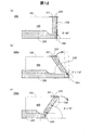
[保護部材の取り外し方法]
図11は、カートリッジ100からの保護部材200の取り外し工程を工程順に示す模式図である。第1工程では、ユーザーがフィルム部201の端部202を支柱部232側に引っ張ることによって、フィルム部201がカートリッジ100の上面102から剥離される。これによって、大気孔128のシール状態が解除されるとともに、支柱部232のカートリッジ100に対する固定状態が解除される。
[How to remove the protective member]
FIG. 11 is a schematic diagram illustrating a process of removing the
第2工程では、ユーザーが操作部233を指先で下方に押すことによって、支柱部232を含む正面端壁部230の全体が接続部240の屈曲部位243を支点として、カートリッジ100から離れる方向に回動移動する。これによって、正面端壁部230の嵌合突起部234がカートリッジ100の嵌合穴113から離れ、その係合状態が解除される。第3工程では、カートリッジ100がキャップ部220から取り外される。これによって、カートリッジ100のインク供給口112がキャップ部220のシール部材250から離間し、インク供給口112の封止状態が解除される。
In the second step, when the user presses the
このように、本実施形態の保護部材200によれば、カートリッジ100からの取り外し操作が簡易に行える。また、本実施形態の保護部材200では、カートリッジ100に装着されている状態では、フィルム部201の溶着によって支柱部232の移動が制限されていることによって、キャップ部220をカートリッジ100から取り外す動作が制限される。フィルム部201がカートリッジ100の上面102から剥離されると、支柱部232の固定状態が解除されて、キャップ部220をカートリッジ100から取り外す動作が可能になる。従って、カートリッジ100からの保護部材200の取り外しの際に、大気孔128とインク供給口112のシール状態の解除順序が規定される。そのため、インク供給口112のシール状態が大気孔128よりも先に解除されてインク供給口112からインク室111内に大気が侵入して、第2のインク保持部材132の近傍領域に滞留してしまうことが抑制される。
Thus, according to the
[保護部材における効果の詳細]
(1)支柱部の配置位置による効果
本実施形態の保護部材200では、支柱部232は、図5,図6において符号FAとして示した領域、すなわち、カートリッジ100が装着された状態においてカートリッジ100の左側面105に対向する領域FAにおいて、左側面105に沿って配置されている。従って、支柱部232の移動可能な方向が左側面105によって規定されるため、支柱部232の誤った移動によってフィルム部201のカートリッジ100に対する溶着状態が損なわれてしまうことが抑制される。保護部材200の取り外しの際にユーザーが支柱部232を誤った方向に移動させてしまう誤操作が抑制される。
[Details of effects in protective member]
(1) Effect by Arrangement Position of Supporting Part In the
本実施形態では、カートリッジ100の前面103には、キャリッジ係合部115が設けられ、その下に回路基板135が配置されている(図2〜図4)。また、カートリッジ100の前面103には、大気孔128を設けるための第1の延出部127が前方に突出している。通常、インクカートリッジの外表面には、例えばキャリッジに対する装着機構を構成する部位などの凹凸が多数形成されている。そのため、インクカートリッジに装着される保護部材はそうした凹凸を考慮しつつインクカートリッジの保護性が高められるように改良されることが望ましい。本実施形態の保護部材200であれば、支柱部232のようなカートリッジ100の高さ方向に延伸する部位がカートリッジ100の前面103に対向する領域には設けられていないため、前面103における複雑に凹凸している構成を考慮する必要がない。従って、保護部材200の構成が複雑化してしまうことが抑制されている。また、保護部材200とカートリッジ100の凹凸面との間に無駄な空間が生じてしまうことが抑制されており、保護部材200によるカートリッジ100の保護性が高められている。
In this embodiment, a
図5を参照する。底面壁部221の壁面に向かう方向(矢印Zの逆方向)に保護部材200を平面視したときの矢印Yの方向における支柱部232の上端面235と底面壁部221の背面壁部223との間の距離をLaとする。また、接続部240と底面壁部221の背面壁部223との間の距離をLbとする。このとき、2つの距離La,Lbは、La≧Lbの関係を満たしていることが望ましい。これによって、支柱部232とフィルム部201との接合部である上端面235が正面端壁部230の回動移動の支点の近くに位置することになり、フィルム部201による支柱部232の固定性が高められる。本実施形態の保護部材200では、2つの距離La,LbはLa>Lbの関係を有しており、フィルム部201による支柱部232の固定性が確保されている。
Please refer to FIG. The
(2)支柱部の形状による効果
図6を参照する。本実施形態では、カートリッジ100の左側面105は、インク供給口112へのインクの流動性を高めるために下方に向くように底面101に対してわずかに傾斜している傾斜部位105sを有している。本実施形態の保護部材200では、支柱部232の左側面105に対向している端部232eがカートリッジ100の左側面105における当該傾斜部位105sに合わせて底面壁部221に対して傾斜している。これによって、カートリッジ100と支柱部232との間に無駄な空間が生じてしまうことが抑制され、保護部材200によるカートリッジ100の保護性が高められている。
(2) Effect by the shape of the support | pillar part Refer FIG. In the present embodiment, the
(3)支柱部の高さによる効果
本実施形態の保護部材200では、カートリッジ100が装着された状態において、支柱部232の上端面235の底面壁部221からの高さ位置とカートリッジ100の上面102における大気孔128の底面壁部221からの高さ位置とが等しくなっている(図6〜図9)。これによって、フィルム部201に捻れや撓みが生じることが抑制され、フィルム部201による大気孔128のシール性が確保しやすくなっている。また、フィルム部201によるカートリッジ100に対する保護部材200の固定性が確保しやすくなっている。
(3) Effect by the Height of the Supporting Column In the
ここで、支柱部232の上端面235は底面壁部221からの高さ位置がカートリッジ100の上面102よりも高い位置にあっても良い。ただし、この場合には、支柱部232に外力が加えられ、その上端面235の位置がぶれたときに、フィルム部201に対して上面102から剥離する方向の力が付与されてしまう可能性がある。また、支柱部232の上端面235は底面壁部221からの高さ位置がカートリッジ100の上面102よりも低い位置にあっても良い。ただし、この場合には、フィルム部201による支柱部232の位置固定性が低下してしまう可能性がある。このように、支柱部232の上端面235の高さ位置とカートリッジ100の上面102における大気孔128の高さ位置とは等しくなっていることが望ましい。ここで言う「等しくなっている」状態とは、実質的に等しい状態を意味しており、支柱部232の上端面235とカートリッジ100の上面102の高さ位置に大きな差異が生じない状態を意味する。「大きな差異が生じない状態」とは、突起部236と大気孔128とに撓みなく接合されたフィルム部201がわずかな外力によって容易に剥離せず接合が維持される程度に支柱部232の上端面235とカートリッジ100の上面102の高さ位置が異なっている状態を意味する。「わずかな外力」とは、例えばユーザーが意図せずしてフィルム部201に触れたときにフィルム部201に付与される程度の外力であるとしても良い。
Here, the
(4)支柱部と上端面の位置関係による効果
図12は、支柱部232の回動移動の支点の位置に対する上端面235の好適位置を説明するための模式図である。図12の(a)欄には本実施形態の保護部材200が図示されており、(b)欄および(c)欄には本実施形態の保護部材200の変形例である保護部材200a,200bが図示されている。変形例の保護部材200a,200bは以下に説明する角度θが異なっている点以外は、本実施形態の保護部材200とほぼ同じ構成を有している。
(4) Effect by Positional Relationship between Support Column and Upper End Surface FIG. 12 is a schematic diagram for explaining a preferred position of the
ここで、矢印Xの方向への平面視において、支柱部232の回動移動の支点となる接続部240の屈曲部位243と支柱部232の上端面235とを最短で結ぶ仮想直線と、底面壁部221の壁面と、の間の角度をθとする。角度θは、接続部240の屈曲部位243から支柱部232の上端面235に向かう方向と、底面壁部221の壁面と、の間の角度に相当する。また、角度θは、支柱部232の延伸方向と、底面壁部221の壁面と、の間の角度であるとの解釈も可能である。なお、以下では角度θは、底面壁部221の壁面を0°として、左回りの方向がプラスである。
Here, in a plan view in the direction of the arrow X, an imaginary straight line that connects the
本実施形態の保護部材200では、角度θは、ほぼ90°になっている((a)欄)。これに対して、変形例の保護部材200aでは、角度θは110°より大きくなっており((b)欄)、変形例の保護部材200bでは、角度θは70°より小さくなっている((c)欄)。
In the
本実施形態の保護部材200では、支柱部232がフィルム部201によって固定されている状態で支柱部232を回動移動させる方向に外力が加えられた場合には、フィルム部201と支柱部232の上端面235との間には主に矢印Yの方向への力が生じる。そうした力は、フィルム部201と上端面235との間の接合力や摩擦力、フィルム部201の張力によって打ち消される。また、本実施形態の保護部材200であれば、上記の場合に、フィルム部201に捻れなどの変形を生じさせる方向への力や、フィルム部201をカートリッジ100や支柱部232から剥離させる方向への力が発生しにくい。このように、本実施形態の保護部材200では、フィルム部201による支柱部232の移動の規制力が確保されている。
In the
変形例の保護部材200a((b)欄)では、図示されている矢印方向への支柱部232の回動移動によって上端面235がカートリッジ100の上面102より上方に移動する。そのため、例えば、支柱部232に誤って矢印Yの方向への外力が付与されたときに、フィルム部201が上方に持ち上げられてしまい、カートリッジ100の上面102から剥離し、支柱部232の回動移動が許容されてしまう可能性がある。ただし、角度θが少なくとも110°以下であれば、そのような可能性が低減される。
In the modified
変形例の保護部材200b((c)欄)では、支柱部232が規定の回動移動方向に既に傾斜しているため、支柱部232が図示されている矢印方向への回動移動がしやすくなっている。また、支柱部232が当該方向に回動移動する場合には、上端面235が下方に移動し、上端面235がフィルム部201から乖離する方向への力が生じることになる。このように、変形例の保護部材200bにおいても、本実施形態の保護部材200よりもフィルム部201による支柱部232の移動の規制力が低下してしまう可能性がある。ただし、角度θが少なくとも70°以上であれば、そのような可能性が低減される。
In the
上記の変形例の保護部材200a,200bのように角度θは110°より大きくても良いし、70°より小さくても良い。ただし、角度θが90°に近いほど、フィルム部201による支柱部232の回動移動を規制する規制力が高められる。よって、角度θは70°以上かつ110°以下(70°≦θ≦110°)であることが望ましく、80°以上かつ100°以下(80°≦θ≦100°)であることがより望ましい。
The angle θ may be larger than 110 ° or smaller than 70 ° as in the
(5)操作部の位置による効果
図6を参照する。本実施形態の保護部材200では、保護部材200を矢印Yの逆方向に沿って見たときに、操作部233は支柱部232に寄った位置、すなわち右側壁部225より左側壁部224に近い位置に形成されている。これによって、支柱部232がフィルム部201によって移動が制限されていることに伴う操作部233の固定性が高められる。よって、ユーザーが操作部233を操作するためにはフィルム部201を先に剥離しなければならないことに気づきやすくなり、カートリッジ100からの保護部材200の取り外しの際の誤操作が抑制される。
(5) Effect by Position of Operation Unit Reference is made to FIG. In the
図7を参照する。本実施形態の保護部材200では、矢印Zの方向において、接続部240の屈曲部位243から操作部233までの距離Lmより接続部240の屈曲部位243から支柱部232の上端面235までの距離Lnの方が長い。すなわち、本実施形態の保護部材200では、操作部233を介して外力が付与される力点が支柱部232の回動移動の支点に近い。よって、支柱部232を回動させるためには操作部233にある程度の大きな力を付与する必要がある。従って、操作部233に誤って外力が付与されて、フィルム部201による支柱部232の固定性が解除されてしまうことが抑制される。
Please refer to FIG. In the
図10を参照する。本実施形態の保護部材200では、カートリッジ100に保護部材200が装着される方向である矢印Zの方向において、底面壁部221から操作部233までの距離Lpは、底面壁部221から嵌合突起部234までの距離Lqより大きい。また、距離Lpは、底面壁部221から支柱部232の上端面235までの距離Lrより小さい。これによって、正面端壁部230の回動移動による嵌合突起部234の係合状態の解除に必要な力よりもフィルム部201による正面端壁部230の回動移動の規制力の方が大きくなる。よって、大気孔128のシール状態より先にインク供給口112のシール状態が解除されてしまうことが抑制される。
Please refer to FIG. In the
[まとめ]
以上のように、本実施形態の保護部材200によれば、カートリッジ100からの取り外し操作が容易化されている。また、カートリッジ100からの取り外しの際の大気孔128とインク供給口112のシール状態の解除の順序の規定が簡易な構成で実現されている。このほかに、本実施形態の保護部材200によれば、保護部材200のカートリッジ100に対する固定性や保護性が高められるなど種々の作用効果が簡易な構成によって達成されている。
[Summary]
As described above, according to the
B.第2実施形態:
図13,図14を参照して、本発明の第2実施形態としての保護部材200Aの構成を説明する。図13は第2実施形態の保護部材200Aの概略上面図である。図14は第2実施形態の保護部材200Aの概略正面図である。図13,図14には、保護部材200Aに取り付けられているときのカートリッジ100の外周輪郭線が破線で図示されている。
B. Second embodiment:
With reference to FIG. 13, FIG. 14, the structure of 200 A of protection members as 2nd Embodiment of this invention is demonstrated. FIG. 13 is a schematic top view of the
第2実施形態の保護部材200Aは、第1実施形態で説明したカートリッジ100(図2〜図4)に装着される。第2実施形態の保護部材200Aは、支柱部232に移動規制突起部237が設けられている点以外は、第1実施形態の保護部材200とほぼ同じ構成である。移動規制突起部237は支柱部232の高さ方向(矢印Zの方向)における中程の位置においてカートリッジ100に向かって突出するように設けられている。
The
移動規制突起部237は、保護部材200Aがカートリッジ100に装着されている状態においてカートリッジ100の左側面105におけるリブ119と係合可能なようにリブ119に隣り合う位置に配置される。移動規制突起部237は、支柱部232が矢印Yの逆方向に回動移動してしまうことをリブ119と係合することによって規制する。
The
第2実施形態の保護部材200Aによれば、カートリッジ100に装着された状態で支柱部232が矢印Yの逆方向に回動移動してしまうことが移動規制突起部237によって抑制される。従って、支柱部232に誤って外力が与えられて支柱部232が回動移動してしまい、フィルム部201が剥離してしまうことが抑制される。従って、保護部材200Aによるカートリッジ100の保護性が高められている。
According to the
ここで、カートリッジ100は、工場からの出荷時などに、保護部材200Aが装着された状態で気密な可撓性膜によって構成された包装部材にくるまれて減圧封止された状態にされる場合がある。この場合であっても、第2実施形態の保護部材200Aであれば、減圧状態に起因する包装部材の押圧によって支柱部232が誤って回動移動してしまうことが移動規制突起部237によって抑制される。従って、工場出荷時におけるカートリッジ100の封止状態が保持される。
Here, when the
以上のように、第2実施形態の保護部材200Aであれば移動規制突起部237によって支柱部232の固定性が高められているため、カートリッジ100の保護性が高められている。また、第2実施形態の保護部材200Aであれば、第1実施形態の保護部材200と同様な作用効果を奏することができる。
As described above, with the
図15は第2実施形態の保護部材の他の構成例を示す概略斜視図である。この構成例の保護部材200Aaは、移動規制突起部237の構成が異なる点以外は、上記の保護部材200Aの構成とほぼ同じである。保護部材200Aaの移動規制突起部237は、保護部材200Aaがカートリッジ100に装着された状態において、カートリッジ100の前面103と係合可能なようにカートリッジ100の前面103に対向する位置に形成されている。このような構成であっても、上記の保護部材200Aと同様な作用効果を奏することができる。
FIG. 15 is a schematic perspective view showing another configuration example of the protection member of the second embodiment. The protection member 200Aa in this configuration example is substantially the same as the configuration of the
C.第3実施形態:
図16は、本発明の第3実施形態としての保護部材200Bの構成を示す概略左側面図である。第3実施形態の保護部材200Bは、接続部240が正面端壁部230の回動移動の支点として機能するヒンジ機構248を有している点以外は、第1実施形態の保護部材200とほぼ同じ構成を有している。第3実施形態の保護部材200Bは、別体として製造されたキャップ部220と正面端壁部230とが、接続部240のヒンジ構造であるヒンジ機構248を介して連結されている。第3実施形態の保護部材200Bによれば、ヒンジ機構248によって、正面端壁部230の回動移動の安定性が高められる。この他に、第3実施形態の保護部材200Bであれば、第1実施形態の保護部材200と対応する構成によって第1実施形態の保護部材200と同様な作用効果を奏することができる。
C. Third embodiment:
FIG. 16 is a schematic left side view showing the configuration of the
D.第4実施形態:
図17は、本発明の第4実施形態としての保護部材200Cの構成を示す概略斜視図である。図17ではカートリッジ100の概略的な外周輪郭線が破線によって図示されている。第4実施形態の保護部材200Cは、第1実施形態で説明したカートリッジ100(図2〜図4)に装着される。第4実施形態の保護部材200Cは、フィルム部201と、ホルダー部210Cと、を備える。フィルム部201は、第1実施形態で説明した構成とほぼ同じである。
D. Fourth embodiment:
FIG. 17 is a schematic perspective view showing the configuration of a
ホルダー部210Cは、キャップ部220Cと、正面端壁部230Cと、を備えている。キャップ部220Cは、正面壁部222を有していない点以外は、第1実施形態のキャップ部220と同様な構成を有し、底面壁部221と、背面壁部223と、左側壁部224と、右側壁部225とを有している。正面端壁部230Cは、前面壁部301と、第1と第2の支柱部302,303と、2本のレール部304,305と、を備える。
The
前面壁部301は、保護部材200Cがカートリッジ100に装着された状態において、カートリッジ100の前面103の下端部と接触する。前面壁部301のカートリッジ100と接触する側の面にはカートリッジ100の各嵌合穴113に嵌合する突起部(図示は省略)が設けられている。
The
第1と第2の支柱部302,303はそれぞれ前面壁部301の左右の端部に連結されている。第1と第2の支柱部302,303は矢印Zの方向に延伸しており、上端面306がカートリッジ100の上面102とほぼ同じ高さ位置にある。第1の支柱部302は、保護部材200Cがカートリッジ100に装着されている状態においてカートリッジ100の左側面105と対向する領域に配置されている。第1の支柱部302の上端面306にはフィルム部201が溶着されている。
The first and
第1と第2のレール部304,305はそれぞれ、第1と第2の支柱部302,303の下端部からキャップ部220Cの左側壁部224および右側壁部225に挟まれた領域内に、左側壁部224および右側壁部225と接触しつつ延伸している。正面端壁部230Cは、第1と第2のレール部304,305によって、キャップ部220Cに対して矢印Yの方向に沿った直線移動のみが可能なように規制されている。
The first and
第4実施形態の保護部材200Cは、カートリッジ100が装着された状態では、フィルム部201によって正面端壁部230Cのカートリッジ100から離れる方向への直線移動が規制されている。従って、フィルム部201をカートリッジ100の上面102から剥離しない限り、ホルダー部210Cにカートリッジ100が係止されている状態が解除されない。従って、カートリッジ100からの保護部材200Cの取り外しの際に、大気孔128より先にインク供給口112のシール状態が解除されてしまうことが抑制される。この他に、第4実施形態の保護部材200Cであれば、第1実施形態の保護部材200と対応する構成によって第1実施形態の保護部材200と同様な作用効果を奏することができる。
In the
E.第5実施形態:
図18は、本発明の第5実施形態としての保護部材200Dの構成を示す概略斜視図である。図18ではカートリッジ100の概略的な外周輪郭線が破線によって図示されている。第5実施形態の保護部材200Dは、第1実施形態で説明したカートリッジ100(図2〜図4)に装着される。第5実施形態の保護部材200Dは、フィルム部201と、ホルダー部210Dと、を備える。フィルム部201は、第1実施形態で説明した構成とほぼ同じである。
E. Fifth embodiment:
FIG. 18 is a schematic perspective view showing the configuration of a
ホルダー部210Dは、キャップ部220Dと、延伸部310と、を備えている。キャップ部220Dは、上方が開口している箱体形状を有しており、カートリッジ100の下端部に嵌合し、カートリッジ100の下端部全体を被覆する。キャップ部220Dは、カートリッジ100のインク供給口112をシールするシール部材(図示は省略)を備えている。
The
延伸部310は、カートリッジ100の左側面105に対向する領域において、キャップ部220Dの端部から矢印Zの方向に延伸している。延伸部310の上端部311はカートリッジ100の上面102とほぼ同じ高さ位置にあり、カートリッジ100の大気孔128と矢印Xの方向に隣り合う位置にある。延伸部310の上端部311にはフィルム部201が溶着されている。
The extending
第5実施形態の保護部材200Dでは、フィルム部201がカートリッジ100の上面102から剥離されない限りは、延伸部310の移動が制限されるため、キャップ部220Dをカートリッジ100の下端から取り外す動作が制限される。従って、第5実施形態の保護部材200Dによれば、カートリッジ100からの保護部材200Dの取り外しの際に、大気孔128より先にインク供給口112のシール状態が解除されてしまうことが、より簡易な構成によって抑制される。この他に、第5実施形態の保護部材200Dであれば、第1実施形態の保護部材200と対応する構成によって第1実施形態の保護部材200と同様な作用効果を奏することができる。
In the
F.変形例:
F1.変形例1:
上記第1実施形態の保護部材200では、大気孔128を封止するシール部材としてテープ状のフィルム部201が用いられている。これに対して、シール部材は、他の構成を有していても良い。例えば、シール部材は、大気孔128を封止するキャップ部と、キャップ部と支柱部232の上端面235との間に架設されるひも部と、によって構成されても良い。この場合には、ひも部は、支柱部232の移動が制限されるように、所定の張力を有するように大気孔128と支柱部232の上端面235との間に張り渡されていることが望ましい。
F. Variations:
F1. Modification 1:
In the
F2.変形例2:
上記第1実施形態の保護部材200では、フィルム部201が接合される支持部は、上方に真っ直ぐに延伸している柱状の支柱部232によって構成されている。これに対して、フィルム部201が接合される支持部は、支柱部232以外によって構成されていても良い。例えば、支持部は、屈曲する部位を有する部材によって構成されても良いし、壁状の部材によって構成されても良い。
F2. Modification 2:
In the
F3.変形例3:
上記第1実施形態の保護部材200では、支柱部232は、保護部材200がカートリッジ100に装着されている状態において、カートリッジ100の左側面105と対向する領域FAに配置されている。これに対して、支柱部232は、カートリッジ100の右側面106と対向する領域に配置されても良い。また、支柱部232は、その全体がカートリッジ100の左側面105と対向する領域FAに配置されていなくても良く、一部がカートリッジ100の前面103や後面104、底面101と対向する領域に配置されていても良い。支柱部232はカートリッジ100の左側面105と直接的に面し合うように対向していなくても良く、支柱部232とカートリッジ100との間には、緩衝材などの別部材が介在されていても良い。
F3. Modification 3:
In the
F4.変形例4:
上記第1実施形態の保護部材200では、キャップ部220は、5つの壁部221〜225を有している。これに対して、キャップ部220は、5つの壁部221〜225の全てを有していなくても良い。キャップ部220は、少なくとも、インク供給口112を封止可能な部位を有していれば良い。
F4. Modification 4:
In the
F5.変形例5:
上記第1実施形態の保護部材200は、カートリッジ100に装着可能に構成されている。これに対して、保護部材200は他の構成を有するカートリッジに装着可能に構成されても良い。保護部材200は大気孔128やインク供給口112をそれぞれ複数個有するカートリッジに装着可能なように、フィルム部201やシール部材250がそれぞれの大気孔128やインク供給口112に対応して設けられても良い。保護部材200は回路基板135やリブ119を有していないカートリッジに装着されても良い。保護部材200が装着されるカートリッジ100は例えば、矢印Xの方向に見たときに、略台形形状を有する6面体として構成されていても良いし、側面視したときに略楕円形状を有する略円板体として構成されても良い。カートリッジ100の外表面を構成する各面101〜106は平坦な表面や平滑な表面を有していなくても良く、凹凸を有していても良い。また、略平面状に延在していなくても良く、切れ目や裂け目があっても良い。各壁面101〜106は略曲面状に曲がっていても良い。加えて、例えば、前面103と左側面105とが交差することなく連続的な曲面を構成しつつ互いに隣り合っていても良いし、前面103と左側面105とが微小な面取り部を挟んで互いに隣り合っていても良い。各壁部101〜106は可撓性を有していても良く、フレームで構成された枠内にインクが収容された袋状部材が保持されている構成であっても良い。
F5. Modification 5:
The
F6.変形例6:
上記第1実施形態の保護部材200は、カートリッジ100に対して係合するため嵌合突起部234や延出部226を有している。これに対して、嵌合突起部234や延出部226は省略されても良い。
F6. Modification 6:
The
F7.変形例7:
上記第1実施形態の保護部材200は、正面端壁部230を回動移動させるための操作部233を支柱部232によった位置に有している。これに対して、操作部233は支柱部232から離間した位置に設けられていても良いし、正面端壁部230から省略されても良い。
F7. Modification 7:
The
F8.変形例8:
上記第1実施形態の保護部材200では、ホルダー部210は、キャップ部220と正面端壁部230と接続部240とが一体成形によって製造されている。これに対して、ホルダー部210は、個別に製造された各構成部が組み付けられることによって製造されても良い。
F8. Modification 8:
In the
本発明は、上述の実施形態や実施例、変形例に限られるものではなく、その趣旨を逸脱しない範囲において種々の構成で実現することができる。例えば、発明の概要の欄に記載した各形態中の技術的特徴に対応する実施形態、実施例、変形例中の技術的特徴は、上述の課題の一部又は全部を解決するために、あるいは、上述の効果の一部又は全部を達成するために、適宜、差し替えや、組み合わせを行うことが可能である。また、その技術的特徴が本明細書中に必須なものとして説明されていなければ、適宜、削除することが可能である。 The present invention is not limited to the above-described embodiments, examples, and modifications, and can be realized with various configurations without departing from the spirit thereof. For example, the technical features in the embodiments, examples, and modifications corresponding to the technical features in each embodiment described in the summary section of the invention are to solve some or all of the above-described problems, or In order to achieve part or all of the above effects, replacement or combination can be performed as appropriate. Further, if the technical feature is not described as essential in the present specification, it can be deleted as appropriate.
100…カートリッジ
101…底面
102…上面
103…前面
104…後面
105…左側面
105s…傾斜部位
106…右側面
110…本体容器
111…インク室
112…インク供給口
113…嵌合穴
114…延伸部
115…キャリッジ係合部
116…突起部
119…リブ
120…蓋部
121…蓋本体部
122…第1のシール部材
123…第2のシール部材
124…中央貫通孔
125a,125b…第1と第2の貫通孔
126…溝
127…第1の延出部
128…大気孔
129…延出部
131…第1のインク保持部材
132…第2のインク保持部材
135…回路基板
200,200a,200b,200A,200Aa,200B,200C…保護部材
201…フィルム部
210,210C,210D…ホルダー部
220,220D…キャップ部
221…底面壁部
222…正面壁部
223…背面壁部
224…左側壁部
225…右側壁部
230,230C…正面端壁部
231…延伸部
232…支柱部
232e…端部
233…操作部
234…嵌合突起部
235…上端面
236…突起部
240…接続部
241…肉厚部
242…薄肉部
243…屈曲部位
245…第1間隙空間
246…第2間隙空間
248…ヒンジ機構
250…シール部材
252…凸壁部
301…前面壁部
302,303…第1と第2の支柱部
304,305…第1と第2のレール部
306…上端面
310…延伸部
311…上端部
DESCRIPTION OF
Claims (11)
前記液体供給口を封止可能なキャップ部材と、
前記大気孔を封止可能なシール部材と、
を備え、
前記キャップ部材は、前記シール部材が接合される接合部を有する支持部を含み、
前記支持部は、前記保護部材が前記液体供給ユニットに装着されている状態において、前記第3壁面に対向する領域に設けられ、前記第1壁面から前記第2壁面に向かう方向に延びている柱状の支柱部を含み、
前記接合部は、前記支柱部の前記第2壁面側の端部に設けられ、
前記支持部は、前記液体供給ユニットから離れる方向への回動移動、または、前記第3壁面に沿った方向であって、前記液体供給ユニットから離れる方向へ直線移動するように構成されている、保護部材。 A first wall surface; a second wall surface facing the first wall surface; a third wall surface between the first wall surface and the second wall surface; and the first wall surface between the first wall surface and the second wall surface. A fourth wall surface adjacent to the three wall surfaces, the first wall surface has a liquid supply port through which liquid flows, the second wall surface has an atmospheric hole through which air flows, and the fourth wall surface has A protective member attachable to a liquid supply unit having an engaging portion,
A cap member capable of sealing the liquid supply port;
A sealing member capable of sealing the air holes;
With
The cap member includes a support portion having a joint portion to which the seal member is joined,
The support portion is provided in a region facing the third wall surface in a state where the protection member is mounted on the liquid supply unit, and extends in a direction from the first wall surface toward the second wall surface. Including the struts of
The joint portion is provided at an end of the column portion on the second wall surface side,
The support portion is configured to rotate in a direction away from the liquid supply unit, or linearly move in a direction along the third wall surface and away from the liquid supply unit . Protective member.
前記キャップ部材は、
前記液体供給口を封止可能な封止部を有する封止壁部と、
前記支持部が設けられ、前記液体供給ユニットに装着された状態において前記液体供給ユニットの前記第4壁面に接触する端壁と、
前記封止壁部と前記端壁とを接続し、前記端壁が前記第4壁面から離れる方向へ回動移動するときの支点となる接続部と、
を備える、保護部材。 The protective member according to claim 1,
The cap member is
A sealing wall portion having a sealing portion capable of sealing the liquid supply port;
An end wall that is provided with the support and is in contact with the fourth wall surface of the liquid supply unit when mounted on the liquid supply unit;
A connecting portion that connects the sealing wall and the end wall, and serves as a fulcrum when the end wall rotates in a direction away from the fourth wall surface;
A protective member.
前記キャップ部材は、
前記封止壁部に交差し、前記液体供給ユニットに装着された状態において前記液体供給ユニットの前記第3壁面と接触する第1側壁と、
前記封止壁部に交差し前記第1側壁に対向する第2側壁と、
を有し、
前記端壁と前記第1側壁とは第1の隙間を介して離間し、前記端壁と前記第2側壁とは第2の隙間を介して離間している、保護部材。 The protective member according to claim 2,
The cap member is
A first side wall that intersects the sealing wall and is in contact with the third wall surface of the liquid supply unit in a state of being attached to the liquid supply unit;
A second side wall that intersects the sealing wall and faces the first side wall;
Have
The protective member, wherein the end wall and the first side wall are separated from each other via a first gap, and the end wall and the second side wall are separated from each other via a second gap.
前記端壁は第1端壁であり、
前記キャップ部材は、前記封止壁部を挟んで前記第1端壁と対向する位置にある第2端壁を有し、
前記封止壁部に向かう方向に前記保護部材を平面視したときに、前記第1端壁から前記第2端壁に向かう方向において、前記支持部の前記接合部から前記第2端壁までの距離Laと、前記接続部から前記第2端壁までの距離Lbとは、La≧Lbの関係を満たす、保護部材。 The protection member according to claim 2 or claim 3,
The end wall is a first end wall;
The cap member has a second end wall at a position facing the first end wall across the sealing wall portion,
When the protective member is viewed in plan in the direction toward the sealing wall, the direction from the first end wall toward the second end wall is from the joint portion of the support portion to the second end wall. The distance La and the distance Lb from the said connection part to the said 2nd end wall are protection members which satisfy | fill the relationship of La> = Lb.
前記保護部材が前記液体供給ユニットに装着されている状態において、前記第3壁面に向かう方向に前記保護部材を平面視したときに、
前記端壁の回動の支点から前記接合部に向かう方向が前記封止壁部に対してなす角度θは、70°≦θ≦110°の範囲にある、保護部材。 The protective member according to any one of claims 2 to 4,
When the protection member is mounted on the liquid supply unit, when the protection member is viewed in a direction toward the third wall surface,
An angle θ formed by a direction from the pivot point of the end wall toward the joint portion with respect to the sealing wall portion is in a range of 70 ° ≦ θ ≦ 110 °.
前記角度θは、80°≦θ≦100°の範囲にある、保護部材。 The protective member according to claim 5,
The angle θ is a protective member in a range of 80 ° ≦ θ ≦ 100 °.
前記端壁は、
前記係合部に係合する被係合部と、
前記被係合部および前記支持部の前記液体供給ユニットに対する位置を変化させるための操作部と、
を有する、保護部材。 The protective member according to any one of claims 2 to 6,
The end wall is
An engaged portion that engages with the engaging portion;
An operation unit for changing positions of the engaged part and the support part with respect to the liquid supply unit;
A protective member.
前記端壁に向かう方向に前記保護部材を平面視したときに、前記操作部は前記支持部に寄った位置に形成されている、保護部材。 The protective member according to claim 7,
The protection member is formed at a position close to the support portion when the protection member is viewed in plan in a direction toward the end wall.
前記接続部から前記操作部までの距離より前記接続部から前記接合部までの距離の方が長い、保護部材。 The protective member according to claim 7 or claim 8,
The protective member whose distance from the said connection part to the said junction part is longer than the distance from the said connection part to the said operation part.
前記保護部材が前記液体供給ユニットに装着される方向において、前記封止壁部から前記操作部までの距離は、前記封止壁部から前記被係合部までの距離より大きく、前記封止壁部から前記接合部までの距離より小さい、保護部材。 The protective member according to any one of claims 7 to 9,
In the direction in which the protection member is attached to the liquid supply unit, a distance from the sealing wall portion to the operation portion is larger than a distance from the sealing wall portion to the engaged portion, and the sealing wall A protective member that is smaller than the distance from the part to the joint.
前記接続部は、ヒンジ構造によって前記端壁を回動させる、保護部材。 The protective member according to claim 2,
The connecting portion is a protective member that rotates the end wall by a hinge structure.
Priority Applications (7)
| Application Number | Priority Date | Filing Date | Title |
|---|---|---|---|
| JP2014078347A JP6241355B2 (en) | 2014-04-07 | 2014-04-07 | Protective member for liquid supply unit |
| PCT/JP2015/001861 WO2015155959A1 (en) | 2014-04-07 | 2015-03-31 | Protection member for liquid supply unit |
| US14/674,926 US9475301B2 (en) | 2014-04-07 | 2015-03-31 | Protection member for liquid supply unit |
| CN201520192805.0U CN204914912U (en) | 2014-04-07 | 2015-04-01 | A guard block for liquid supply unit |
| CN201510153596.3A CN104972765B (en) | 2014-04-07 | 2015-04-01 | For the guard block of fluid supply unit |
| EP15162379.0A EP2930028B1 (en) | 2014-04-07 | 2015-04-02 | Protection member for liquid supply unit |
| TW104111021A TW201600347A (en) | 2014-04-07 | 2015-04-02 | Protection member for liquid supply unit |
Applications Claiming Priority (1)
| Application Number | Priority Date | Filing Date | Title |
|---|---|---|---|
| JP2014078347A JP6241355B2 (en) | 2014-04-07 | 2014-04-07 | Protective member for liquid supply unit |
Publications (3)
| Publication Number | Publication Date |
|---|---|
| JP2015199227A JP2015199227A (en) | 2015-11-12 |
| JP2015199227A5 JP2015199227A5 (en) | 2017-05-18 |
| JP6241355B2 true JP6241355B2 (en) | 2017-12-06 |
Family
ID=53002487
Family Applications (1)
| Application Number | Title | Priority Date | Filing Date |
|---|---|---|---|
| JP2014078347A Active JP6241355B2 (en) | 2014-04-07 | 2014-04-07 | Protective member for liquid supply unit |
Country Status (6)
| Country | Link |
|---|---|
| US (1) | US9475301B2 (en) |
| EP (1) | EP2930028B1 (en) |
| JP (1) | JP6241355B2 (en) |
| CN (2) | CN104972765B (en) |
| TW (1) | TW201600347A (en) |
| WO (1) | WO2015155959A1 (en) |
Families Citing this family (4)
| Publication number | Priority date | Publication date | Assignee | Title |
|---|---|---|---|---|
| JP6241355B2 (en) * | 2014-04-07 | 2017-12-06 | セイコーエプソン株式会社 | Protective member for liquid supply unit |
| JP2017094660A (en) * | 2015-11-27 | 2017-06-01 | セイコーエプソン株式会社 | Liquid supply unit |
| JP6753054B2 (en) | 2015-11-27 | 2020-09-09 | セイコーエプソン株式会社 | Liquid storage container and protective member |
| RU2643770C1 (en) * | 2017-02-06 | 2018-02-05 | Юлия Алексеевна Щепочкина | Cast iron |
Family Cites Families (29)
| Publication number | Priority date | Publication date | Assignee | Title |
|---|---|---|---|---|
| US5262802A (en) | 1989-09-18 | 1993-11-16 | Canon Kabushiki Kaisha | Recording head assembly with single sealing member for ejection outlets and for an air vent |
| DE69511461T2 (en) * | 1994-05-31 | 2000-04-13 | Canon Kk | Interchangeable ink cartridge with locking structure |
| AU688545B2 (en) | 1994-08-24 | 1998-03-12 | Canon Kabushiki Kaisha | Ink container for ink jet printer, holder for the container carriage for the holder and ink jet printer |
| JPH08230205A (en) | 1995-02-28 | 1996-09-10 | Canon Inc | Ink tank protecting method and membur and ink tank having protecting member |
| KR100191040B1 (en) * | 1995-09-14 | 1999-06-15 | 미따라이 하지메 | A scanner head cartridge and an information processing device thereof |
| JPH09284471A (en) * | 1996-04-18 | 1997-10-31 | Canon Inc | Scanner head cartridge, its using method and information processor using the scanner head cartridge |
| JP3768633B2 (en) | 1997-02-14 | 2006-04-19 | キヤノン株式会社 | Inkjet cartridge and printing apparatus |
| US6283587B1 (en) * | 1998-03-20 | 2001-09-04 | Seiko Epson Corporation | Printer ink cartridge and ink cartridge device including the same |
| JP2000255082A (en) | 1999-03-09 | 2000-09-19 | Canon Inc | Packaging method of ink jet cartridge for ink jet recoding |
| JP2001001544A (en) | 1999-06-24 | 2001-01-09 | Canon Inc | Liquid supply method, liquid supply container, negative pressure generating member storing container, and liquid storing container |
| JP2001071534A (en) * | 1999-09-03 | 2001-03-21 | Canon Inc | Printing apparatus |
| US7178911B2 (en) * | 2001-03-30 | 2007-02-20 | Brother Kogyo Kabushiki Kaisha | Ink cartridge |
| JP4250433B2 (en) * | 2002-03-18 | 2009-04-08 | キヤノン株式会社 | Packaging structure of liquid container and method for opening the same |
| MXPA03002490A (en) | 2002-03-20 | 2004-10-15 | Seiko Epson Corp | Ink cartridge and ink cartridge holder. |
| JP4261819B2 (en) * | 2002-04-26 | 2009-04-30 | キヤノン株式会社 | Ink tank packaging container and ink tank using the packaging container |
| JP2005153506A (en) * | 2003-11-07 | 2005-06-16 | Canon Finetech Inc | Ink tank package and its unsealing method |
| JP2006021476A (en) | 2004-07-09 | 2006-01-26 | Canon Inc | Packaging structure of liquid storage vessel |
| JP2007022035A (en) * | 2005-07-21 | 2007-02-01 | Canon Inc | Protective cap for liquid receptacle and liquid receptacle |
| JP4347278B2 (en) * | 2005-08-25 | 2009-10-21 | キヤノン株式会社 | Cap used for liquid container |
| CN200939736Y (en) | 2006-08-02 | 2007-08-29 | 珠海天威技术开发有限公司 | Ink box and its protector |
| JP4664944B2 (en) * | 2007-06-18 | 2011-04-06 | 株式会社リコー | Refill ink cartridge |
| US20090251514A1 (en) * | 2008-04-08 | 2009-10-08 | Static Control Components, Inc. | Universal ink cartridge seal |
| CN201483896U (en) * | 2009-08-24 | 2010-05-26 | 珠海中润靖杰打印机耗材有限公司 | Inkjet cartridge with protective cover |
| JP3169008U (en) * | 2011-04-26 | 2011-07-07 | エステー産業株式会社 | Ink cartridge package |
| US20130286113A1 (en) * | 2012-04-30 | 2013-10-31 | Joseph W. Hoff | Ink tank seal retainer with symmetric seal force |
| US8894184B2 (en) * | 2012-05-23 | 2014-11-25 | Seiko Epson Corporation | Cover and liquid container |
| CN202847118U (en) * | 2012-10-15 | 2013-04-03 | 珠海中润靖杰打印机耗材有限公司 | Ink box with rotatingly buckling type protective cover |
| WO2015093008A1 (en) * | 2013-12-18 | 2015-06-25 | セイコーエプソン株式会社 | Liquid supply unit |
| JP6241355B2 (en) * | 2014-04-07 | 2017-12-06 | セイコーエプソン株式会社 | Protective member for liquid supply unit |
-
2014
- 2014-04-07 JP JP2014078347A patent/JP6241355B2/en active Active
-
2015
- 2015-03-31 US US14/674,926 patent/US9475301B2/en active Active
- 2015-03-31 WO PCT/JP2015/001861 patent/WO2015155959A1/en active Application Filing
- 2015-04-01 CN CN201510153596.3A patent/CN104972765B/en active Active
- 2015-04-01 CN CN201520192805.0U patent/CN204914912U/en not_active Expired - Fee Related
- 2015-04-02 TW TW104111021A patent/TW201600347A/en unknown
- 2015-04-02 EP EP15162379.0A patent/EP2930028B1/en active Active
Also Published As
| Publication number | Publication date |
|---|---|
| US9475301B2 (en) | 2016-10-25 |
| TW201600347A (en) | 2016-01-01 |
| JP2015199227A (en) | 2015-11-12 |
| WO2015155959A1 (en) | 2015-10-15 |
| EP2930028B1 (en) | 2019-05-29 |
| EP2930028A2 (en) | 2015-10-14 |
| EP2930028A3 (en) | 2016-07-13 |
| CN204914912U (en) | 2015-12-30 |
| CN104972765B (en) | 2017-03-29 |
| CN104972765A (en) | 2015-10-14 |
| US20150284159A1 (en) | 2015-10-08 |
Similar Documents
| Publication | Publication Date | Title |
|---|---|---|
| US9399352B2 (en) | Liquid container | |
| JP6753054B2 (en) | Liquid storage container and protective member | |
| JP6241355B2 (en) | Protective member for liquid supply unit | |
| US8308279B2 (en) | Sealing device for fluid reservoir | |
| JP2001105617A (en) | Liquid housing container, cap used therein and liquid housing container with cap | |
| JP6111748B2 (en) | Liquid container container, liquid supply device, and liquid ejection device | |
| US10124596B2 (en) | Supply apparatus | |
| JP2007015272A (en) | Recording head and sealing member used therefor | |
| JP2001105619A (en) | Ink cartridge | |
| JP2018001579A (en) | Supply device | |
| JP2007022035A (en) | Protective cap for liquid receptacle and liquid receptacle | |
| JP2017043086A (en) | Ink jet recording apparatus | |
| JP2017043086A5 (en) | ||
| EP4140748A1 (en) | Ink cartridge having print head | |
| US8807722B2 (en) | Ink cartridge and inkjet printer | |
| JP2017105102A (en) | Liquid storage container and liquid storage structure | |
| JP2013212656A (en) | Inkjet recorder | |
| JP6000419B1 (en) | Inkjet recording device | |
| JP2018202613A (en) | Protective member and cartridge | |
| JPH1034973A (en) | Case for stocking ink jet cartridge | |
| JP2018065361A (en) | Supply device | |
| JP2007230190A (en) | Liquid storage container and recorder | |
| JP2008200883A (en) | Inkjet cartridge | |
| JP2009241512A (en) | Storage case of ejection head unit | |
| JP2016129939A (en) | Sealing member and liquid storing container |
Legal Events
| Date | Code | Title | Description |
|---|---|---|---|
| A521 | Request for written amendment filed |
Free format text: JAPANESE INTERMEDIATE CODE: A523 Effective date: 20170330 |
|
| A621 | Written request for application examination |
Free format text: JAPANESE INTERMEDIATE CODE: A621 Effective date: 20170330 |
|
| TRDD | Decision of grant or rejection written | ||
| A01 | Written decision to grant a patent or to grant a registration (utility model) |
Free format text: JAPANESE INTERMEDIATE CODE: A01 Effective date: 20171010 |
|
| A61 | First payment of annual fees (during grant procedure) |
Free format text: JAPANESE INTERMEDIATE CODE: A61 Effective date: 20171023 |
|
| R150 | Certificate of patent or registration of utility model |
Ref document number: 6241355 Country of ref document: JP Free format text: JAPANESE INTERMEDIATE CODE: R150 |