JP6748171B2 - Touch panel device, touch panel device control method, program, and storage medium storing program - Google Patents
Touch panel device, touch panel device control method, program, and storage medium storing program Download PDFInfo
- Publication number
- JP6748171B2 JP6748171B2 JP2018199021A JP2018199021A JP6748171B2 JP 6748171 B2 JP6748171 B2 JP 6748171B2 JP 2018199021 A JP2018199021 A JP 2018199021A JP 2018199021 A JP2018199021 A JP 2018199021A JP 6748171 B2 JP6748171 B2 JP 6748171B2
- Authority
- JP
- Japan
- Prior art keywords
- electrode
- drive
- unit
- touch panel
- state
- Prior art date
- Legal status (The legal status is an assumption and is not a legal conclusion. Google has not performed a legal analysis and makes no representation as to the accuracy of the status listed.)
- Active
Links
Images


Classifications
-
- G—PHYSICS
- G06—COMPUTING; CALCULATING OR COUNTING
- G06F—ELECTRIC DIGITAL DATA PROCESSING
- G06F3/00—Input arrangements for transferring data to be processed into a form capable of being handled by the computer; Output arrangements for transferring data from processing unit to output unit, e.g. interface arrangements
- G06F3/01—Input arrangements or combined input and output arrangements for interaction between user and computer
- G06F3/03—Arrangements for converting the position or the displacement of a member into a coded form
- G06F3/041—Digitisers, e.g. for touch screens or touch pads, characterised by the transducing means
- G06F3/0416—Control or interface arrangements specially adapted for digitisers
- G06F3/0418—Control or interface arrangements specially adapted for digitisers for error correction or compensation, e.g. based on parallax, calibration or alignment
- G06F3/04182—Filtering of noise external to the device and not generated by digitiser components
-
- G—PHYSICS
- G06—COMPUTING; CALCULATING OR COUNTING
- G06F—ELECTRIC DIGITAL DATA PROCESSING
- G06F3/00—Input arrangements for transferring data to be processed into a form capable of being handled by the computer; Output arrangements for transferring data from processing unit to output unit, e.g. interface arrangements
- G06F3/01—Input arrangements or combined input and output arrangements for interaction between user and computer
- G06F3/03—Arrangements for converting the position or the displacement of a member into a coded form
- G06F3/041—Digitisers, e.g. for touch screens or touch pads, characterised by the transducing means
- G06F3/0412—Digitisers structurally integrated in a display
-
- G—PHYSICS
- G06—COMPUTING; CALCULATING OR COUNTING
- G06F—ELECTRIC DIGITAL DATA PROCESSING
- G06F3/00—Input arrangements for transferring data to be processed into a form capable of being handled by the computer; Output arrangements for transferring data from processing unit to output unit, e.g. interface arrangements
- G06F3/01—Input arrangements or combined input and output arrangements for interaction between user and computer
- G06F3/03—Arrangements for converting the position or the displacement of a member into a coded form
- G06F3/041—Digitisers, e.g. for touch screens or touch pads, characterised by the transducing means
- G06F3/0416—Control or interface arrangements specially adapted for digitisers
- G06F3/04166—Details of scanning methods, e.g. sampling time, grouping of sub areas or time sharing with display driving
-
- G—PHYSICS
- G06—COMPUTING; CALCULATING OR COUNTING
- G06F—ELECTRIC DIGITAL DATA PROCESSING
- G06F3/00—Input arrangements for transferring data to be processed into a form capable of being handled by the computer; Output arrangements for transferring data from processing unit to output unit, e.g. interface arrangements
- G06F3/01—Input arrangements or combined input and output arrangements for interaction between user and computer
- G06F3/03—Arrangements for converting the position or the displacement of a member into a coded form
- G06F3/041—Digitisers, e.g. for touch screens or touch pads, characterised by the transducing means
- G06F3/044—Digitisers, e.g. for touch screens or touch pads, characterised by the transducing means by capacitive means
- G06F3/0446—Digitisers, e.g. for touch screens or touch pads, characterised by the transducing means by capacitive means using a grid-like structure of electrodes in at least two directions, e.g. using row and column electrodes
-
- G—PHYSICS
- G06—COMPUTING; CALCULATING OR COUNTING
- G06F—ELECTRIC DIGITAL DATA PROCESSING
- G06F2203/00—Indexing scheme relating to G06F3/00 - G06F3/048
- G06F2203/041—Indexing scheme relating to G06F3/041 - G06F3/045
- G06F2203/04112—Electrode mesh in capacitive digitiser: electrode for touch sensing is formed of a mesh of very fine, normally metallic, interconnected lines that are almost invisible to see. This provides a quite large but transparent electrode surface, without need for ITO or similar transparent conductive material
Description
本発明は、操作子にタッチされた位置に応じた信号を出力するタッチパネルを有するタッチパネル装置、タッチパネル装置の制御方法、プログラムおよびプログラムを記憶する記憶媒体に関する。 The present invention relates to a touch panel device having a touch panel that outputs a signal corresponding to a position touched by an operator, a control method for the touch panel device, a program, and a storage medium that stores the program.
下記特許文献1には、各X軸電極が駆動電極となり各Y軸電極が検出電極になる状態と、各X軸電極が検出電極となり各Y軸電極が駆動電極となる状態とを所定タイミングで切り替えるように制御するものが開示されている。
In
上記特許文献1の技術では、複数列のX電極パターンの検出電圧から操作面上に配置された指先の横方向の位置が検出され、複数列のY電極パターンの検出電圧から操作面上に配置された指先の縦方向の位置が検出されるため、操作に対するタッチパネル装置の応答性が悪化する問題があった。
In the technique of
本発明は、上記の問題を解決するためになされたものであり、操作子による操作に対する応答性を向上させることができるタッチパネル装置、タッチパネル装置の制御方法、プログラムおよびプログラムを記憶する記憶媒体を提供することを目的とする。 The present invention has been made to solve the above problems, and provides a touch panel device, a touch panel device control method, a program, and a storage medium that stores the program, which can improve the responsiveness to the operation by an operator. The purpose is to
本発明の第1の態様は、第1の方向に延びて設けられた複数列の第1電極と、前記第1の方向に直交する第2の方向に延びて設けられた複数列の第2電極と、を備えるタッチパネルを有するタッチパネル装置であって、前記第1電極および前記第2電極の一方の駆動電極に対して駆動パルス信号を送信する駆動部と、前記第1電極および前記第2電極の他方の検出電極が検出した検出信号を1列毎に受信する受信部と、前記第1電極を前記駆動電極として前記駆動部と接続させ、前記第2電極を前記検出電極として前記受信部と接続させる第1状態と、前記第2電極を前記駆動電極として前記駆動部と接続させ、前記第1電極を前記検出電極として前記受信部と接続させる第2状態とを切り替える切替部と、複数の前記駆動電極に対して順に設定周波数の前記駆動パルス信号を送信するように前記駆動部を制御する駆動制御部と、前記タッチパネル上を格子状に区画し、前記駆動部が前記駆動パルス信号を送信した前記駆動電極の列と、前記受信部が前記検出信号を受信した前記検出電極の列との組み合わせにより1つの区画を特定し、前記受信部が受信した前記検出信号の強度を特定した前記区画における信号強度とする信号強度取得部と、前記検出電極の検出信号にノイズが含まれることを判定するノイズ判定部と、前記検出信号にノイズが含まれると判定された場合に、前記第1状態と前記第2状態とを切り替えるように前記切替部を制御する切替制御部と、前記検出信号にノイズが含まれると判定されていない場合には、前記第1状態において前記信号強度が第1閾値以上である区画を操作子の操作位置として取得し、前記検出信号にノイズが含まれると判定された場合には、前記第1状態において前記信号強度が前記第1閾値以上であって、かつ、前記第2状態において前記信号強度が前記第1閾値以上である区画を前記操作子の前記操作位置として取得する操作位置取得部と、を有する。 According to a first aspect of the present invention, a plurality of rows of first electrodes are provided extending in a first direction, and a plurality of rows of second electrodes are provided extending in a second direction orthogonal to the first direction. A touch panel device having a touch panel including an electrode, the drive unit transmitting a drive pulse signal to one of the first electrode and the second electrode, and the first electrode and the second electrode. A receiving unit that receives a detection signal detected by the other detecting electrode for each column, a first electrode connected to the driving unit as the driving electrode, and a second electrode serving as the detecting electrode and the receiving unit. A switching unit that switches between a first state in which the second electrode is connected to the driving unit as the driving electrode and a second state in which the first electrode is connected to the receiving unit as the detection electrode; A drive control unit that controls the drive unit to sequentially transmit the drive pulse signal of a set frequency to the drive electrodes, and the touch panel is divided into a grid pattern, and the drive unit transmits the drive pulse signal. One section is specified by a combination of the row of the drive electrodes and the row of the detection electrodes where the receiving section has received the detection signal, and the section where the intensity of the detection signal received by the receiving section is specified. Signal strength acquisition unit for determining the signal strength of the detection electrode, a noise determination unit that determines that the detection signal of the detection electrode includes noise, and the first state when it is determined that the detection signal includes noise. And a switching control unit that controls the switching unit to switch between the second state and the second state, and if it is not determined that the detection signal contains noise, the signal strength is the first threshold in the first state. When the section as above is acquired as the operation position of the operator, and it is determined that the detection signal includes noise, the signal intensity in the first state is equal to or higher than the first threshold, and An operation position acquisition unit that acquires, as the operation position of the operator, a section in which the signal intensity is equal to or higher than the first threshold value in the second state.
本発明の第2の態様は、第1の方向に延びて設けられた複数列の第1電極と、前記第1の方向に直交する第2の方向に延びて設けられた複数列の第2電極と、を備えるタッチパネルを有するタッチパネル装置の制御方法であって、前記タッチパネル装置は、前記第1電極および前記第2電極の一方の駆動電極に対して駆動パルス信号を送信する駆動部と、前記第1電極および前記第2電極の他方の検出電極が検出した検出信号を1列毎に受信する受信部と、前記第1電極を前記駆動電極として前記駆動部と接続させ、前記第2電極を前記検出電極として前記受信部と接続させる第1状態と、前記第2電極を前記駆動電極として前記駆動部と接続させ、前記第1電極を前記検出電極として前記受信部と接続させる第2状態とを切り替える切替部と、を有し、複数の前記駆動電極に対して順に設定周波数の前記駆動パルス信号を送信するように前記駆動部を制御する駆動制御ステップと、前記タッチパネル上を格子状に区画し、前記駆動部が前記駆動パルス信号を送信した前記駆動電極の列と、前記受信部が前記検出信号を受信した前記検出電極の列との組み合わせにより1つの区画を特定し、前記受信部が受信した前記検出信号の強度を特定した前記区画における信号強度とする信号強度取得ステップと、前記検出電極の検出信号にノイズが含まれることを判定するノイズ判定ステップと、前記検出信号にノイズが含まれると判定された場合に、前記第1状態と前記第2状態とを切り替えるように前記切替部を制御する切替制御ステップと、前記検出信号にノイズが含まれると判定されていない場合には、前記第1状態において前記信号強度が第1閾値以上である区画を操作子の操作位置として取得し、前記検出信号にノイズが含まれると判定された場合には、前記第1状態において前記信号強度が前記第1閾値以上であって、かつ、前記第2状態において前記信号強度が前記第1閾値以上である区画を前記操作子の前記操作位置として取得する操作位置取得ステップと、を有する。 According to a second aspect of the present invention, a plurality of rows of first electrodes provided extending in a first direction and a plurality of rows of second electrodes provided extending in a second direction orthogonal to the first direction. A method for controlling a touch panel device having a touch panel including an electrode, wherein the touch panel device includes a drive unit that transmits a drive pulse signal to one of the first electrode and the second electrode. A receiving unit that receives, for each column, a detection signal detected by the other detection electrode of the first electrode and the second electrode, and the first electrode is connected to the driving unit as the driving electrode, and the second electrode is connected to the receiving unit. A first state in which the detection electrode is connected to the reception unit, and a second state in which the second electrode is connected to the drive unit as the drive electrode and the first electrode is connected to the reception unit as the detection electrode And a drive control step of controlling the drive unit so as to sequentially transmit the drive pulse signal of the set frequency to the plurality of drive electrodes, and a partition on the touch panel in a grid pattern. Then, one section is specified by a combination of the row of the drive electrodes to which the drive section has transmitted the drive pulse signal and the row of the detection electrodes to which the reception section has received the detection signal, and the reception section A signal strength acquisition step of setting the strength of the received detection signal as the signal strength in the section, a noise determination step of determining that the detection signal of the detection electrode contains noise, and a noise included in the detection signal. If it is determined that the detection signal contains noise, a switching control step of controlling the switching unit to switch between the first state and the second state, and if it is not determined that the detection signal includes noise, When it is determined that a section in which the signal intensity is equal to or higher than a first threshold value in the first state is acquired as the operation position of the operator and the detection signal includes noise, the signal intensity in the first state is set. Is equal to or more than the first threshold value, and in the second state, an operation position acquisition step of acquiring a section in which the signal intensity is equal to or more than the first threshold value as the operation position of the operator.
本発明の第3の態様は、第2の態様のタッチパネル装置の制御方法をコンピュータに実行させる、プログラムである。 A third aspect of the present invention is a program that causes a computer to execute the touch panel device control method of the second aspect.
本発明の第4の態様は、第2の態様のタッチパネル装置の制御方法をコンピュータに実行させる、プログラムを記憶する記憶媒体である。 A fourth aspect of the present invention is a storage medium for storing a program that causes a computer to execute the method for controlling the touch panel device of the second aspect.
本発明によれば、操作子による操作に対する応答性を向上させることができる。 According to the present invention, it is possible to improve the responsiveness to the operation by the operator.
〔第1の実施の形態〕
[タッチパネル装置の構成]
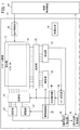
図1は、タッチパネル装置10の構成を示すブロック図である。タッチパネル装置10は、ユーザが指やスタイラス等の操作子で、画像等が表示された表示部12上を触れることによって操作が行われる入力装置である。本実施の形態のタッチパネル装置10は、図示しない工作機械を制御する数値制御装置14の入力装置として用いられる。
[First Embodiment]
[Configuration of touch panel device]
FIG. 1 is a block diagram showing the configuration of the
タッチパネル装置10は、表示部12、表示制御部16、タッチパネル18、第1切替部20、第1駆動部22、第1受信部24、第2切替部26、第2駆動部28、第2受信部30、駆動制御部32、信号強度取得部34、操作位置取得部36、ノイズ判定部38および切替制御部40を有している。
The
表示部12は、液晶ディスプレイ等であって、ユーザが数値制御装置14に対して指令を入力するためのアイコン、数値制御装置14から送られてくる工作機械の状況を示す情報等を表示する。表示制御部16は、数値制御装置14の要求にしたがって表示部12を制御する。
The
タッチパネル18は、表示部12の画面に貼着された透明なフィルム状の部材である。本実施の形態のタッチパネル18は相互容量方式のタッチパネルである。
The
図2は、タッチパネル18の構造を示す模式図である。タッチパネル18は、酸化インジウム錫により形成されたX軸電極Ex[1]〜Ex[m]とY軸電極Ey[1]〜Ey[n]を有している。X軸電極Ex[1]〜Ex[m]は、図2のY軸方向に延びて配置され、X軸方向にm列設けられている。Y軸電極Ey[1]〜Ey[n]は、図2のX軸方向に延びて配置され、Y軸方向にn列設けられている。
FIG. 2 is a schematic diagram showing the structure of the
Y軸電極Ey[1]〜Ey[n]には、第1切替部20を介して第1駆動部22と第1受信部24が接続されている。X軸電極Ex[1]〜Ex[m]には、第2切替部26を介して第2受信部30と第2駆動部28が接続されている。
The
第1切替部20は、Y軸電極Ey[1]〜Ey[n]と第1駆動部22とを接続する第1状態と、Y軸電極Ey[1]〜Ey[n]と第1受信部24とを接続する第2状態とを切り替える。第1状態において、Y軸電極Ey[1]〜Ey[n]は駆動電極となり、第2状態において、Y軸電極Ey[1]〜Ey[n]は検出電極となる。
The
第2切替部26は、X軸電極Ex[1]〜Ex[m]と第2受信部30とを接続する第1状態と、X軸電極Ex[1]〜Ex[m]と第2駆動部28とを接続する第2状態とを切り替える。第1状態において、X軸電極Ex[1]〜Ex[m]は検出電極となり、第2状態において、X軸電極Ex[1]〜Ex[m]は駆動電極となる。
The
第1駆動部22は、第1状態において、Y軸電極Ey[1]〜Ey[n]のそれぞれに駆動パルス信号を送信する。図3は、第1駆動部22からY軸電極Ey[1]〜Ey[n]のそれぞれに入力される駆動パルス信号を示すグラフである。第1駆動部22は、Y軸電極Ey[1]〜Ey[n]に順番に、あらかじめ設定されている設定周波数の駆動パルス信号を30パルスずつ送信する。なお、駆動パルス信号のパルス数は30パルスに限らなくともよい。第2駆動部28は、第2状態において、上記と同様にX軸電極Ex[1]〜Ex[m]のそれぞれに駆動パルス信号を送信する。
In the first state, the
第2受信部30は、第1状態において、X軸電極Ex[1]〜Ex[m]のそれぞれの検出信号を受信する。第2受信部30は、Y軸電極Ey[1]〜Ey[n]からX軸電極Ex[1]〜Ex[m]に流れる電流を検出し、検出した電流を電圧に変換する。タッチパネル18に操作子が接触しておらず、ノイズの影響がない状況では、X軸電極Ex[1]〜Ex[m]の電圧の振幅はV0となる。タッチパネル18に操作子が接触すると、Y軸電極Ey[1]〜Ey[n]からX軸電極Ex[1]〜Ex[m]に流れていた電流の一部が操作子側に流れるため、X軸電極Ex[1]〜Ex[m]の電圧の振幅はV0よりも小さくなる。第2受信部30は、電圧V0と検出した電圧の振幅であるVとの差分|V0−V|を用いて検出信号を計算する。検出信号の強度が閾値以上であるときに、第2受信部30は所定の位置に操作子が触れたことを認識する。第1受信部24は、第2状態において、上記と同様に、Y軸電極Ey[1]〜Ey[n]のそれぞれの検出信号を受信する。
The second receiving
以下では、X軸電極Ex[1]〜Ex[m]の列を区別しない場合には、X軸電極Exと記載することがある。また、以下では、Y軸電極Ey[1]〜Ey[n]の列を区別しない場合には、Y軸電極Eyと記載することがある。 Hereinafter, when the columns of the X-axis electrodes Ex[1] to Ex[m] are not distinguished, they may be referred to as the X-axis electrodes Ex. Further, hereinafter, when the columns of the Y-axis electrodes Ey[1] to Ey[n] are not distinguished, they may be referred to as Y-axis electrodes Ey.
図1に戻り、駆動制御部32は、第1状態において、設定周波数の駆動パルス信号をY軸電極Ey[1]からY軸電極Ey[n]まで順に送信するスキャンを繰り返し行うように第1駆動部22を制御する。駆動制御部32は、第2状態において、設定周波数の駆動パルス信号をX軸電極Ex[1]からX軸電極Ex[m]まで順に送信するスキャンを繰り返し行うように第2駆動部28を制御する。
Returning to FIG. 1, in the first state, the
信号強度取得部34は、タッチパネル18上を格子状に区画した区画S[1、1]〜S[m、n]毎の信号強度を取得する。図4は、タッチパネル18上を格子状に区画した状態の模式図である。図4には、区画S[1、1]〜S[m、n]の境界を示す線が記載されているが、実際のタッチパネル18には区画S[1、1]〜S[m、n]の境界を示す線は見えていない。
The signal
信号強度取得部34は、第1状態において、第1駆動部22が駆動パルス信号を送信したY軸電極Eyの列と、第2受信部30が検出信号を受信したX軸電極Exの列との組み合わせから、操作子がタッチパネル18に接触している位置(以下、操作位置)に対応する区画S[1、1]〜S[m、n]を特定する。そして、信号強度取得部34は、検出信号の強度を、特定した区画S[1、1]〜S[m、n]の信号強度として取得する。例えば、第1駆動部22がY軸電極Ey[3]に駆動パルス信号を送信し、第2受信部30がX軸電極Ex[4]の検出信号を受信した場合には、信号強度取得部34は、操作子の操作位置として区画S[4、3]を特定する。そして、信号強度取得部34は、X軸電極Ex[4]の検出信号の強度を、区画S[4、3]における信号強度として取得する。信号強度取得部34は、上記と同様にして、第2状態において、第2駆動部28が駆動パルス信号を送信したX軸電極Exの列と、第1受信部24が検出信号を受信したY軸電極Eyの列との組み合わせから、操作子の操作位置に対応する区画S[1、1]〜S[m、n]を特定する。以下、区画S[1、1]〜S[m、n]を区別しない場合には、区画Sと記載することがある。
In the first state, the signal
操作位置取得部36は、信号強度取得部34が取得した各区画Sの信号強度に応じて、操作子の操作位置を取得する。操作位置取得部36は、例えば、信号強度が第1閾値である区画Sの位置を操作位置として取得する。操作位置取得部36による操作子の操作位置の取得は、後に詳述する。
The operation
ノイズ判定部38は、第1状態において、信号強度取得部34が取得した各区画Sの信号強度に応じて、検出信号にノイズが発生していることを判定する。ノイズ判定部38によるノイズの発生の判定については、後に詳述する。
The
切替制御部40は、ノイズ判定部38において、検出信号にノイズが発生していると判定された場合には、第1状態と第2状態とを所定の周期で切り替えるように第1切替部20と第2切替部26を制御する。
When the
なお、駆動制御部32、信号強度取得部34、操作位置取得部36、ノイズ判定部38および切替制御部40は、記憶媒体42に記憶されているプログラムがコンピュータにより実行されることにより実現される。
The
[ノイズ判定処理]
ノイズ判定部38は、第1状態において、先のスキャンが行われたときの信号強度が第2閾値以上であって、次のスキャンが行われたときの信号強度が第2閾値未満である区画Sがある場合には、検出信号にノイズが含まれると判定する。第2閾値は、第1閾値以下の値に設定される。
[Noise determination processing]
In the first state, the
なお、上記では、ノイズ判定部38は、スキャンが2回行われた場合に、区画Sのうち、信号強度が第2閾値以上である回数が1回以上2回未満である場合に、検出信号にノイズが含まれると判定しているが、スキャンの回数や、信号強度が第2閾値以上である回数は、適宜設定してよい。
In the above description, the
[操作位置取得処理]
図5は、操作位置取得部36において行われる操作位置取得処理の流れを示すフローチャートである。
[Operation position acquisition process]
FIG. 5 is a flowchart showing the flow of the operation position acquisition process performed by the operation
ステップS1において、操作位置取得部36は、検出信号にノイズが含まれているか否かを判定する。検出信号にノイズが含まれている場合にはステップS2に移行し、検出信号にノイズが含まれていない場合にはステップS5に移行する。
In step S1, the operation
ステップS2において、操作位置取得部36は、第1状態における各区画Sの信号強度を取得する。
In step S2, the operation
ステップS3において、操作位置取得部36は、第2状態における各区画Sの信号強度を取得する。
In step S3, the operation
ステップS4において、操作位置取得部36は、第1状態における信号強度が第1閾値以上、かつ、第2状態における信号強度が第1閾値以上である区画Sを操作位置として取得する。
In step S4, the operation
ステップS5において、操作位置取得部36は、第1状態における各区画Sの信号強度を取得する。
In step S5, the operation
ステップS6において、操作位置取得部36は、第1状態における信号強度が第1閾値以上である区画Sを操作位置として取得して、処理を終了する。
In step S6, the operation
図6A〜図6Cは、操作位置取得方法について説明する図である。図6Aは、第1状態における信号強度が第1閾値以上であった区画Sを灰色で塗りつぶし、図6Bは、第2状態における信号強度が第1閾値以上であった区画Sを灰色で塗りつぶしている。 6A to 6C are diagrams illustrating the operation position acquisition method. In FIG. 6A, the section S in which the signal strength in the first state is equal to or higher than the first threshold value is filled with gray, and in FIG. 6B, the section S in which the signal strength in the second state is equal to or higher than the first threshold value is filled with gray. There is.
図6Aに示されるように、第1状態において区画S[7、4]、区画S[7、11]、区画S[7、n−1]の信号強度が第1閾値以上であった。また、図6Bに示されるように、第2状態において区画S[3、11]、区画S[7、11]、区画S[m−1、11]の信号強度が第1閾値以上であった。この場合、操作位置取得部36は、図6Cに黒で塗りつぶした区画S[7、11]を操作位置として取得する。
As shown in FIG. 6A, in the first state, the signal intensities of the section S[7,4], the section S[7,11], and the section S[7,n-1] were equal to or higher than the first threshold value. Further, as shown in FIG. 6B, in the second state, the signal intensities of the section S[3,11], the section S[7,11], and the section S[m−1,11] were not less than the first threshold value. .. In this case, the operation
[作用効果]
操作位置取得部36が、Y軸電極Ey[1]〜Ey[n]を駆動電極とし、X軸電極Ex[1]〜Ex[m]を検出電極とする第1状態と、X軸電極Ex[1]〜Ex[m]を駆動電極とし、Y軸電極Ey[1]〜Ey[n]を検出電極とする第2状態の両方において、信号強度が第1閾値以上である区画Sを操作位置として取得することにより、ノイズ耐性を向上させることができる。しかし、Y軸電極Ey[1]〜Ey[n]のスキャンと、X軸電極Ex[1]〜Ex[m]のスキャンがそれぞれ行われる必要があり、操作に対するタッチパネル装置10の応答性が悪化する問題があった。
[Effect]
The operation
そこで、本実施の形態のタッチパネル装置10では、操作位置取得部36は、検出信号にノイズが含まれると判定されていない場合には、第1状態において取得された各区画Sの信号強度に基づいて操作子の操作位置を取得し、検出信号にノイズが含まれると判定された場合には、第1状態において取得された各区画Sの信号強度と第2状態において取得された各区画Sの信号強度とに基づいて操作子の操作位置を取得するようにした。
Therefore, in the
これにより、検出信号にノイズが含まれると判定されていない場合には、操作に対するタッチパネル装置10の応答性を向上させることができ、検出信号にノイズが含まれると判定された場合には、タッチパネル装置10のノイズ耐性を向上させることができる。
Thereby, when it is determined that the detection signal does not include noise, the responsiveness of the
また、本実施の形態のタッチパネル装置10では、ノイズ判定部38は、第1状態において、第1駆動部22または第2駆動部28が、各列の駆動電極に対して順に駆動パルス信号を送信するスキャンを2回行った場合に、区画Sのうち、信号強度が第2閾値以上である回数が1回以上2回未満である区画Sがある場合には、検出信号にノイズが含まれると判定するようにした。操作子がタッチパネル18に接触している場合に、第2受信部30が検出信号を受信している時間の長さに対して、第2受信部30がノイズを受信する時間の長さは短い。そのため、信号強度が第2閾値以上である回数が所定回数未満である区画Sがある場合には、検出信号にノイズが含まれると判定することができる。
Further, in the
〔実施の形態から得られる技術的思想〕
上記実施の形態から把握しうる技術的思想について、以下に記載する。
[Technical ideas obtained from the embodiments]
The technical ideas that can be understood from the above-described embodiment will be described below.
第1の方向に延びて設けられた複数列の第1電極(Ey)と、前記第1の方向に直交する第2の方向に延びて設けられた複数列の第2電極(Ex)と、を備えるタッチパネル(18)を有するタッチパネル装置(10)であって、前記第1電極および前記第2電極の一方の駆動電極に対して駆動パルス信号を送信する駆動部(22、28)と、前記第1電極および前記第2電極の他方の検出電極が検出した検出信号を1列毎に受信する受信部(24、30)と、前記第1電極を前記駆動電極として前記駆動部と接続させ、前記第2電極を前記検出電極として前記受信部と接続させる第1状態と、前記第2電極を前記駆動電極として前記駆動部と接続させ、前記第1電極を前記検出電極として前記受信部と接続させる第2状態とを切り替える切替部(20、26)と、複数の前記駆動電極に対して順に設定周波数の前記駆動パルス信号を送信するように前記駆動部を制御する駆動制御部(32)と、前記タッチパネル上を格子状に区画し、前記駆動部が前記駆動パルス信号を送信した前記駆動電極の列と、前記受信部が前記検出信号を受信した前記検出電極の列との組み合わせにより1つの区画(S)を特定し、前記受信部が受信した前記検出信号の強度を特定した前記区画における信号強度とする信号強度取得部(34)と、前記検出電極の検出信号にノイズが含まれることを判定するノイズ判定部(38)と、前記検出信号にノイズが含まれると判定された場合に、前記第1状態と前記第2状態とを切り替えるように前記切替部を制御する切替制御部(40)と、前記検出信号にノイズが含まれると判定されていない場合には、前記第1状態において前記信号強度が第1閾値以上である区画を操作子の操作位置として取得し、前記検出信号にノイズが含まれると判定された場合には、前記第1状態において前記信号強度が前記第1閾値以上であって、かつ、前記第2状態において前記信号強度が前記第1閾値以上である区画を前記操作子の前記操作位置として取得する操作位置取得部(36)と、をする。これにより、検出信号にノイズが含まれると判定されていない場合には、操作に対するタッチパネル装置の応答性を向上させることができ、検出信号にノイズが含まれると判定された場合には、タッチパネル装置のノイズ耐性を向上させることができる。 A plurality of columns of first electrodes (Ey) provided extending in a first direction, and a plurality of columns of second electrodes (Ex) provided extending in a second direction orthogonal to the first direction, A touch panel device (10) having a touch panel (18) comprising: a drive unit (22, 28) for transmitting a drive pulse signal to one drive electrode of the first electrode and the second electrode; A receiving unit (24, 30) for receiving the detection signal detected by the other detection electrode of the first electrode and the second electrode for each column, and connecting the first electrode as the driving electrode to the driving unit, A first state in which the second electrode is connected as the detection electrode to the receiving unit, and a state in which the second electrode is connected as the drive electrode to the driving unit and the first electrode is connected as the detection electrode to the receiving unit A switching unit (20, 26) for switching between the second state to be driven, and a drive control unit (32) for controlling the drive unit so as to sequentially transmit the drive pulse signal of the set frequency to the plurality of drive electrodes. , A combination of a row of the drive electrodes to which the drive section transmits the drive pulse signal and a row of the detection electrodes to which the reception section has received the detection signal A signal strength acquisition unit (34) that specifies a section (S) and that is the signal strength in the section that specifies the strength of the detection signal received by the reception unit, and that the detection signal of the detection electrode includes noise. And a switching control unit (38) that controls the switching unit to switch between the first state and the second state when it is determined that the detection signal contains noise. 40) and if it is not determined that the detection signal contains noise, a section in which the signal intensity is equal to or higher than a first threshold value is acquired as the operation position of the operator in the first state, and the detection signal is acquired. When it is determined that noise is included in the section, the signal strength in the first state is equal to or higher than the first threshold, and the signal strength in the second state is equal to or higher than the first threshold. And an operation position acquisition unit (36) for acquiring as the operation position of the operator. Accordingly, the response of the touch panel device to the operation can be improved when it is not determined that the detection signal includes noise, and the touch panel device can be improved when the detection signal is determined to include noise. The noise resistance of can be improved.
上記のタッチパネル装置であって、前記ノイズ判定部は、前記第1状態において、前記駆動部が各列の前記駆動電極に対して順に前記駆動パルス信号を送信するスキャンを複数回行った場合に、前記区画のうち、前記信号強度が第2閾値以上である回数が1回以上所定回数未満である区画がある場合には、前記検出信号にノイズが含まれると判定してもよい。これにより、ノイズ判定部は、第1状態において、検出信号にノイズが含まれることの判定を行うことができる。 In the above touch panel device, the noise determination unit, in the first state, when the drive unit performs a plurality of scans for sequentially transmitting the drive pulse signal to the drive electrodes of each column, If there is a section in which the signal intensity is equal to or more than the second threshold value is one or more and less than the predetermined number of times, it may be determined that the detection signal includes noise. Thereby, the noise determination unit can determine that the detection signal includes noise in the first state.
第1の方向に延びて設けられた複数列の第1電極(Ey)と、前記第1の方向に直交する第2の方向に延びて設けられた複数列の第2電極(Ex)と、を備えるタッチパネル(18)を有するタッチパネル装置(10)の制御方法であって、前記タッチパネル装置は、前記第1電極および前記第2電極の一方の駆動電極に対して駆動パルス信号を送信する駆動部(22、28)と、前記第1電極および前記第2電極の他方の検出電極が検出した検出信号を1列毎に受信する受信部(24、30)と、前記第1電極を前記駆動電極として前記駆動部と接続させ、前記第2電極を前記検出電極として前記受信部と接続させる第1状態と、前記第2電極を前記駆動電極として前記駆動部と接続させ、前記第1電極を前記検出電極として前記受信部と接続させる第2状態とを切り替える切替部(20、26)と、を有し、複数の前記駆動電極に対して順に設定周波数の前記駆動パルス信号を送信するように前記駆動部を制御する駆動制御ステップと、前記タッチパネル上を格子状に区画し、前記駆動部が前記駆動パルス信号を送信した前記駆動電極の列と、前記受信部が前記検出信号を受信した前記検出電極の列との組み合わせにより1つの区画を特定し、前記受信部が受信した前記検出信号の強度を特定した前記区画における信号強度とする信号強度取得ステップと、前記検出電極の検出信号にノイズが含まれることを判定するノイズ判定ステップと、前記検出信号にノイズが含まれると判定された場合に、前記第1状態と前記第2状態とを切り替えるように前記切替部を制御する切替制御ステップと、前記検出信号にノイズが含まれると判定されていない場合には、前記第1状態において前記信号強度が第1閾値以上である区画を操作子の操作位置として取得し、前記検出信号にノイズが含まれると判定された場合には、前記第1状態において前記信号強度が前記第1閾値以上であって、かつ、前記第2状態において前記信号強度が前記第1閾値以上である区画を前記操作子の前記操作位置として取得する操作位置取得ステップと、を有する。これにより、検出信号にノイズが含まれると判定されていない場合には、操作に対するタッチパネル装置の応答性を向上させることができ、検出信号にノイズが含まれると判定された場合には、タッチパネル装置のノイズ耐性を向上させることができる。 A plurality of columns of first electrodes (Ey) provided extending in a first direction, and a plurality of columns of second electrodes (Ex) provided extending in a second direction orthogonal to the first direction, A method for controlling a touch panel device (10) having a touch panel (18) comprising: a drive unit for transmitting a drive pulse signal to one drive electrode of the first electrode and the second electrode. (22, 28), a receiving unit (24, 30) that receives the detection signal detected by the other detection electrode of the first electrode and the second electrode for each column, and the first electrode as the drive electrode. And a second state in which the second electrode is connected to the receiving section as the detection electrode, and the second electrode is connected to the driving section as the drive electrode, and the first electrode is A switching unit (20, 26) for switching between a second state in which the detection electrode is connected to the receiving unit, and the drive pulse signal having the set frequency is sequentially transmitted to the plurality of drive electrodes. A drive control step of controlling a drive unit, a row of the drive electrodes that divides the touch panel into a grid pattern, the drive unit transmits the drive pulse signal, and the detection unit that the reception unit receives the detection signal. A signal strength acquisition step of specifying one section by a combination with an electrode row and setting the strength of the detection signal received by the receiving unit as the signal strength in the section, and noise in the detection signal of the detection electrode. A noise determination step of determining that the switching signal is included, and a switching control step of controlling the switching unit to switch between the first state and the second state when it is determined that the detection signal includes noise. When the detection signal is not determined to include noise, a section in which the signal intensity is equal to or higher than a first threshold value is acquired as the operation position of the operator in the first state, and the detection signal has noise. If it is determined to be included, in the first state, the signal intensity is equal to or higher than the first threshold value, and in the second state, the signal intensity is equal to or higher than the first threshold value. An operation position acquisition step of acquiring the operation position of the child. Accordingly, the response of the touch panel device to the operation can be improved when it is not determined that the detection signal includes noise, and the touch panel device can be improved when the detection signal is determined to include noise. The noise resistance of can be improved.
上記のタッチパネル装置の制御方法であって、前記ノイズ判定ステップは、前記第1状態において、前記駆動部が各列の前記駆動電極に対して順に前記駆動パルス信号を送信するスキャンを複数回行った場合に、前記区画のうち、前記信号強度が第2閾値以上である回数が1回以上所定回数未満である区画がある場合には、前記検出信号にノイズが含まれると判定してもよい。これにより、ノイズ判定ステップは、第1状態において、検出信号にノイズが含まれることの判定を行うことができる。 In the above-mentioned touch panel device control method, in the noise determination step, in the first state, the drive section sequentially performs a scan in which the drive pulse signals are transmitted to the drive electrodes in each column, a plurality of times. In this case, if there is a section in which the signal intensity is equal to or more than the second threshold value is one or more and less than the predetermined number of times, it may be determined that the detection signal includes noise. Accordingly, the noise determination step can determine that the detection signal contains noise in the first state.
上記のタッチパネル装置の制御方法をコンピュータに実行させる、プログラム。これにより、検出信号にノイズが含まれると判定されていない場合には、操作に対するタッチパネル装置の応答性を向上させることができ、検出信号にノイズが含まれると判定された場合には、タッチパネル装置のノイズ耐性を向上させることができる。 A program that causes a computer to execute the above-described control method for the touch panel device. Accordingly, the response of the touch panel device to the operation can be improved when it is not determined that the detection signal includes noise, and the touch panel device can be improved when the detection signal is determined to include noise. The noise resistance of can be improved.
上記のタッチパネル装置の制御方法をコンピュータに実行させる、プログラムを記憶する記憶媒体(42)。これにより、検出信号にノイズが含まれると判定されていない場合には、操作に対するタッチパネル装置の応答性を向上させることができ、検出信号にノイズが含まれると判定された場合には、タッチパネル装置のノイズ耐性を向上させることができる。 A storage medium (42) for storing a program, which causes a computer to execute the control method of the touch panel device. Accordingly, the response of the touch panel device to the operation can be improved when it is not determined that the detection signal includes noise, and the touch panel device can be improved when the detection signal is determined to include noise. The noise resistance of can be improved.
10…タッチパネル装置 18…タッチパネル
20…第1切替部(切替部) 22…第1駆動部(駆動部)
24…第1受信部(受信部) 26…第2切替部(切替部)
28…第2駆動部(駆動部) 30…第2受信部(受信部)
34…信号強度取得部 36…操作位置取得部
38…ノイズ判定部 40…切替制御部
Ex…X軸電極(第2電極) Ey…Y軸電極(第1電極)
10...
24... 1st receiving part (receiving part) 26... 2nd switching part (switching part)
28... 2nd drive part (drive part) 30... 2nd receiving part (receiving part)
34... Signal
Claims (6)
前記第1の方向に直交する第2の方向に延びて設けられた複数列の第2電極と、
を備えるタッチパネルを有するタッチパネル装置であって、
前記第1電極および前記第2電極の一方の駆動電極に対して駆動パルス信号を送信する駆動部と、
前記第1電極および前記第2電極の他方の検出電極が検出した検出信号を1列毎に受信する受信部と、
前記第1電極を前記駆動電極として前記駆動部と接続させ、前記第2電極を前記検出電極として前記受信部と接続させる第1状態と、前記第2電極を前記駆動電極として前記駆動部と接続させ、前記第1電極を前記検出電極として前記受信部と接続させる第2状態とを切り替える切替部と、
複数の前記駆動電極に対して順に設定周波数の前記駆動パルス信号を送信するように前記駆動部を制御する駆動制御部と、
前記タッチパネル上を格子状に区画し、前記駆動部が前記駆動パルス信号を送信した前記駆動電極の列と、前記受信部が前記検出信号を受信した前記検出電極の列との組み合わせにより1つの区画を特定し、前記受信部が受信した前記検出信号の強度を特定した前記区画における信号強度とする信号強度取得部と、
前記検出電極の検出信号にノイズが含まれることを判定するノイズ判定部と、
前記検出信号にノイズが含まれると判定された場合に、前記第1状態と前記第2状態とを切り替えるように前記切替部を制御する切替制御部と、
前記検出信号にノイズが含まれると判定されていない場合には、前記第1状態において前記信号強度が第1閾値以上である区画を操作子の操作位置として取得し、前記検出信号にノイズが含まれると判定された場合には、前記第1状態において前記信号強度が前記第1閾値以上であって、かつ、前記第2状態において前記信号強度が前記第1閾値以上である区画を前記操作子の前記操作位置として取得する操作位置取得部と、
を有する、タッチパネル装置。 A plurality of rows of first electrodes provided to extend in a first direction,
A plurality of rows of second electrodes provided extending in a second direction orthogonal to the first direction;
A touch panel device having a touch panel comprising:
A drive unit that transmits a drive pulse signal to one of the first electrode and the second electrode,
A receiving unit that receives, for each column, a detection signal detected by the other detection electrode of the first electrode and the second electrode,
A first state in which the first electrode is connected to the drive unit as the drive electrode and the second electrode is connected to the reception unit as the detection electrode, and the second electrode is connected to the drive unit as the drive electrode And a switching unit that switches between the second state in which the first electrode is connected to the receiving unit as the detection electrode,
A drive control unit that controls the drive unit so as to transmit the drive pulse signal having a set frequency to the plurality of drive electrodes in order;
The touch panel is divided into a grid shape, and one division is formed by a combination of the row of the drive electrodes to which the drive section has transmitted the drive pulse signal and the row of the detection electrodes to which the reception section has received the detection signal. And a signal strength acquisition unit that is the signal strength in the section that specifies the strength of the detection signal received by the reception unit,
A noise determination unit that determines that the detection signal of the detection electrode contains noise,
A switching control unit that controls the switching unit to switch between the first state and the second state when it is determined that the detection signal contains noise;
When it is not determined that the detection signal includes noise, a section in which the signal intensity is equal to or higher than a first threshold value is acquired as the operation position of the operator in the first state, and the detection signal includes noise. If it is determined that the signal strength is equal to or higher than the first threshold value in the first state and the signal strength is equal to or higher than the first threshold value in the second state, An operation position acquisition unit that acquires as the operation position of
A touch panel device having:
前記ノイズ判定部は、前記第1状態において、前記駆動部が各列の前記駆動電極に対して順に前記駆動パルス信号を送信するスキャンを複数回行った場合に、前記区画のうち、前記信号強度が第2閾値以上である回数が1回以上所定回数未満である区画がある場合には、前記検出信号にノイズが含まれると判定する、タッチパネル装置。 The touch panel device according to claim 1, wherein
In the first state, when the drive unit performs a plurality of scans in which the drive pulse signal is sequentially transmitted to the drive electrodes of each column, the noise determination unit outputs the signal intensity in the section. The touch panel device, which determines that the detection signal includes noise when there is a section in which the number of times is equal to or more than the second threshold value is one time or more and less than the predetermined number of times.
前記第1の方向に直交する第2の方向に延びて設けられた複数列の第2電極と、
を備えるタッチパネルを有するタッチパネル装置の制御方法であって、
前記タッチパネル装置は、
前記第1電極および前記第2電極の一方の駆動電極に対して駆動パルス信号を送信する駆動部と、
前記第1電極および前記第2電極の他方の検出電極が検出した検出信号を1列毎に受信する受信部と、
前記第1電極を前記駆動電極として前記駆動部と接続させ、前記第2電極を前記検出電極として前記受信部と接続させる第1状態と、前記第2電極を前記駆動電極として前記駆動部と接続させ、前記第1電極を前記検出電極として前記受信部と接続させる第2状態とを切り替える切替部と、
を有し、
複数の前記駆動電極に対して順に設定周波数の前記駆動パルス信号を送信するように前記駆動部を制御する駆動制御ステップと、
前記タッチパネル上を格子状に区画し、前記駆動部が前記駆動パルス信号を送信した前記駆動電極の列と、前記受信部が前記検出信号を受信した前記検出電極の列との組み合わせにより1つの区画を特定し、前記受信部が受信した前記検出信号の強度を特定した前記区画における信号強度とする信号強度取得ステップと、
前記検出電極の検出信号にノイズが含まれることを判定するノイズ判定ステップと、
前記検出信号にノイズが含まれると判定された場合に、前記第1状態と前記第2状態とを切り替えるように前記切替部を制御する切替制御ステップと、
前記検出信号にノイズが含まれると判定されていない場合には、前記第1状態において前記信号強度が第1閾値以上である区画を操作子の操作位置として取得し、前記検出信号にノイズが含まれると判定された場合には、前記第1状態において前記信号強度が前記第1閾値以上であって、かつ、前記第2状態において前記信号強度が前記第1閾値以上である区画を前記操作子の前記操作位置として取得する操作位置取得ステップと、
を有する、タッチパネル装置の制御方法。 A plurality of rows of first electrodes provided to extend in a first direction,
A plurality of rows of second electrodes provided extending in a second direction orthogonal to the first direction;
A method for controlling a touch panel device having a touch panel comprising:
The touch panel device,
A drive unit that transmits a drive pulse signal to one drive electrode of the first electrode and the second electrode;
A receiving unit that receives, for each column, a detection signal detected by the other detection electrode of the first electrode and the second electrode,
A first state in which the first electrode is connected to the drive unit as the drive electrode and the second electrode is connected to the reception unit as the detection electrode, and the second electrode is connected to the drive unit as the drive electrode And a switching unit that switches between a second state in which the first electrode is connected to the receiving unit as the detection electrode,
Have
A drive control step of controlling the drive section so as to transmit the drive pulse signal of the set frequency to the plurality of drive electrodes in order;
The touch panel is divided into a grid shape, and one division is formed by a combination of a row of the drive electrodes to which the drive section has transmitted the drive pulse signal and a row of the detection electrodes to which the reception section has received the detection signal. A signal strength acquisition step of specifying the signal strength in the section that specifies the strength of the detection signal received by the receiving unit,
A noise determination step of determining that the detection signal of the detection electrode contains noise,
A switching control step of controlling the switching unit to switch between the first state and the second state when it is determined that the detection signal contains noise,
When it is not determined that the detection signal includes noise, a section in which the signal strength is equal to or higher than a first threshold value is acquired as the operation position of the operator in the first state, and the detection signal includes noise. If it is determined that the signal strength is equal to or higher than the first threshold in the first state, and the signal strength is equal to or higher than the first threshold in the second state, the operator is defined as a section. An operation position acquisition step of acquiring as the operation position of
A method for controlling a touch panel device, comprising:
前記ノイズ判定ステップは、前記第1状態において、前記駆動部が各列の前記駆動電極に対して順に前記駆動パルス信号を送信するスキャンを複数回行った場合に、前記区画のうち、前記信号強度が第2閾値以上である回数が1回以上所定回数未満である区画がある場合には、前記検出信号にノイズが含まれると判定する、タッチパネル装置の制御方法。 The control method of the touch panel device according to claim 3,
In the noise determination step, in the first state, when the drive unit performs a plurality of scans in which the drive pulse signals are sequentially transmitted to the drive electrodes in each column, the signal intensity in the partition is determined. Is a second threshold value or more, and when there is a section whose number of times is 1 or more and less than a predetermined number of times, it is determined that the detection signal includes noise.
Priority Applications (5)
| Application Number | Priority Date | Filing Date | Title |
|---|---|---|---|
| JP2018199021A JP6748171B2 (en) | 2018-10-23 | 2018-10-23 | Touch panel device, touch panel device control method, program, and storage medium storing program |
| DE102019128182.2A DE102019128182B4 (en) | 2018-10-23 | 2019-10-18 | TOUCH PANEL DEVICE, CONTROL METHOD FOR TOUCH PANEL DEVICE, PROGRAM AND STORAGE MEDIUM THAT STORES THE PROGRAM |
| US16/656,645 US10895935B2 (en) | 2018-10-23 | 2019-10-18 | Touch panel device, touch panel device control method, program, and storage medium storing the program |
| TW108137803A TWI716157B (en) | 2018-10-23 | 2019-10-21 | Touch panel device, touch panel device control method, program, and storage medium storing the program |
| CN201911005718.9A CN111090354B (en) | 2018-10-23 | 2019-10-22 | Touch panel device, control method thereof, and storage medium storing program |
Applications Claiming Priority (1)
| Application Number | Priority Date | Filing Date | Title |
|---|---|---|---|
| JP2018199021A JP6748171B2 (en) | 2018-10-23 | 2018-10-23 | Touch panel device, touch panel device control method, program, and storage medium storing program |
Publications (2)
| Publication Number | Publication Date |
|---|---|
| JP2020067733A JP2020067733A (en) | 2020-04-30 |
| JP6748171B2 true JP6748171B2 (en) | 2020-08-26 |
Family
ID=70279509
Family Applications (1)
| Application Number | Title | Priority Date | Filing Date |
|---|---|---|---|
| JP2018199021A Active JP6748171B2 (en) | 2018-10-23 | 2018-10-23 | Touch panel device, touch panel device control method, program, and storage medium storing program |
Country Status (5)
| Country | Link |
|---|---|
| US (1) | US10895935B2 (en) |
| JP (1) | JP6748171B2 (en) |
| CN (1) | CN111090354B (en) |
| DE (1) | DE102019128182B4 (en) |
| TW (1) | TWI716157B (en) |
Families Citing this family (1)
| Publication number | Priority date | Publication date | Assignee | Title |
|---|---|---|---|---|
| US11182038B2 (en) * | 2020-04-08 | 2021-11-23 | Sigmasense, Llc. | Encoded data pattern touchscreen sensing system |
Family Cites Families (15)
| Publication number | Priority date | Publication date | Assignee | Title |
|---|---|---|---|---|
| JP5496735B2 (en) | 2010-03-30 | 2014-05-21 | 株式会社ワコム | Indicator position detection apparatus and indicator position detection method |
| JP5890664B2 (en) | 2011-11-25 | 2016-03-22 | 京セラディスプレイ株式会社 | Touch panel device |
| US20160357327A1 (en) * | 2012-05-18 | 2016-12-08 | Egalax_Empia Technology Inc. | Touch sensitive system and apparatus and method for measuring signals of touch sensitive screen |
| US9411928B2 (en) | 2012-07-17 | 2016-08-09 | Parade Technologies, Ltd. | Discontinuous integration using half periods |
| KR101725134B1 (en) * | 2012-08-09 | 2017-04-11 | (주)멜파스 | Apparatus and method for sensing of touch |
| CN102945110B (en) | 2012-11-29 | 2016-01-27 | 旭曜科技股份有限公司 | The noise filtering method of capacitance type touch-control panel and system |
| KR102127861B1 (en) | 2013-03-05 | 2020-06-30 | 삼성전자주식회사 | Capacitive touch system with improved touch sensing precision and coordinates extracting method therefore |
| JP6101123B2 (en) * | 2013-03-18 | 2017-03-22 | アルプス電気株式会社 | Capacitive touchpad |
| JP5982624B2 (en) * | 2013-09-30 | 2016-08-31 | Smk株式会社 | Capacitive touch panel |
| TWI515634B (en) | 2013-11-08 | 2016-01-01 | 義隆電子股份有限公司 | Touch device and sensing method for of the touch device |
| CN104461138B (en) * | 2014-12-05 | 2017-07-04 | 京东方科技集团股份有限公司 | The driving method of touch-control display panel, device and touch-control display panel |
| CN105739795B (en) | 2014-12-12 | 2018-09-21 | 宸鸿科技(厦门)有限公司 | Capacitance type touch-control panel and its sensing method of touch control |
| US9874983B2 (en) * | 2015-06-23 | 2018-01-23 | Synaptics Incorporated | Electrode combining for noise determination |
| US10761634B2 (en) * | 2016-07-06 | 2020-09-01 | Sharp Kabushiki Kaisha | Touch panel control device and electronic device |
| WO2018053700A1 (en) | 2016-09-21 | 2018-03-29 | 华为技术有限公司 | Interference suppression method and device for touch panel |
-
2018
- 2018-10-23 JP JP2018199021A patent/JP6748171B2/en active Active
-
2019
- 2019-10-18 DE DE102019128182.2A patent/DE102019128182B4/en active Active
- 2019-10-18 US US16/656,645 patent/US10895935B2/en active Active
- 2019-10-21 TW TW108137803A patent/TWI716157B/en active
- 2019-10-22 CN CN201911005718.9A patent/CN111090354B/en active Active
Also Published As
| Publication number | Publication date |
|---|---|
| TW202024881A (en) | 2020-07-01 |
| CN111090354B (en) | 2021-07-16 |
| JP2020067733A (en) | 2020-04-30 |
| DE102019128182A1 (en) | 2020-04-23 |
| DE102019128182B4 (en) | 2021-03-25 |
| CN111090354A (en) | 2020-05-01 |
| TWI716157B (en) | 2021-01-11 |
| US20200125231A1 (en) | 2020-04-23 |
| US10895935B2 (en) | 2021-01-19 |
Similar Documents
| Publication | Publication Date | Title |
|---|---|---|
| KR102297484B1 (en) | Display device and driving method thereof | |
| JP6415710B2 (en) | Display device with sensor, control device, and control method | |
| CN102339156A (en) | Driving method, driving device and touch display device | |
| JP6748171B2 (en) | Touch panel device, touch panel device control method, program, and storage medium storing program | |
| US10860158B2 (en) | Touch panel device, touch panel device control method, and non-transitory tangible computer-readable storage medium having the program stored therein | |
| US10949033B2 (en) | Touch panel device, touch panel device control method, and non-transitory tangible computer-readable storage medium having the program stored therein | |
| JP6882252B2 (en) | A non-temporary tangible computer-readable storage medium that stores a touch panel device, a control method of the touch panel device, a program, and a program. | |
| JP7204416B2 (en) | Touch panel device, control method for touch panel device, program, and storage medium for storing program | |
| JP6912447B2 (en) | A non-temporary tangible computer-readable storage medium that stores a touch panel device, a control method of the touch panel device, a program, and a program. | |
| JP5797950B2 (en) | Multi touch panel device | |
| JP7264615B2 (en) | Touch panel device, control method for touch panel device, program, and storage medium for storing program | |
| JP7204415B2 (en) | Touch panel device, control method for touch panel device, program, and storage medium for storing program | |
| WO2014171177A1 (en) | Touch-panel device, display device with touch panel, and program | |
| JP2015207033A (en) | Touch panel device and touch detection method | |
| JP2014081719A (en) | Manipulation device |
Legal Events
| Date | Code | Title | Description |
|---|---|---|---|
| A621 | Written request for application examination |
Free format text: JAPANESE INTERMEDIATE CODE: A621 Effective date: 20200323 |
|
| A871 | Explanation of circumstances concerning accelerated examination |
Free format text: JAPANESE INTERMEDIATE CODE: A871 Effective date: 20200616 |
|
| A975 | Report on accelerated examination |
Free format text: JAPANESE INTERMEDIATE CODE: A971005 Effective date: 20200701 |
|
| TRDD | Decision of grant or rejection written | ||
| A01 | Written decision to grant a patent or to grant a registration (utility model) |
Free format text: JAPANESE INTERMEDIATE CODE: A01 Effective date: 20200707 |
|
| A61 | First payment of annual fees (during grant procedure) |
Free format text: JAPANESE INTERMEDIATE CODE: A61 Effective date: 20200806 |
|
| R150 | Certificate of patent or registration of utility model |
Ref document number: 6748171 Country of ref document: JP Free format text: JAPANESE INTERMEDIATE CODE: R150 |