JP6748006B2 - Pressure sensor - Google Patents
Pressure sensor Download PDFInfo
- Publication number
- JP6748006B2 JP6748006B2 JP2017044554A JP2017044554A JP6748006B2 JP 6748006 B2 JP6748006 B2 JP 6748006B2 JP 2017044554 A JP2017044554 A JP 2017044554A JP 2017044554 A JP2017044554 A JP 2017044554A JP 6748006 B2 JP6748006 B2 JP 6748006B2
- Authority
- JP
- Japan
- Prior art keywords
- pressure
- temperature
- diaphragm
- detection device
- inner container
- Prior art date
- Legal status (The legal status is an assumption and is not a legal conclusion. Google has not performed a legal analysis and makes no representation as to the accuracy of the status listed.)
- Active
Links
Images


Classifications
-
- G—PHYSICS
- G01—MEASURING; TESTING
- G01L—MEASURING FORCE, STRESS, TORQUE, WORK, MECHANICAL POWER, MECHANICAL EFFICIENCY, OR FLUID PRESSURE
- G01L9/00—Measuring steady of quasi-steady pressure of fluid or fluent solid material by electric or magnetic pressure-sensitive elements; Transmitting or indicating the displacement of mechanical pressure-sensitive elements, used to measure the steady or quasi-steady pressure of a fluid or fluent solid material, by electric or magnetic means
- G01L9/12—Measuring steady of quasi-steady pressure of fluid or fluent solid material by electric or magnetic pressure-sensitive elements; Transmitting or indicating the displacement of mechanical pressure-sensitive elements, used to measure the steady or quasi-steady pressure of a fluid or fluent solid material, by electric or magnetic means by making use of variations in capacitance, i.e. electric circuits therefor
- G01L9/125—Measuring steady of quasi-steady pressure of fluid or fluent solid material by electric or magnetic pressure-sensitive elements; Transmitting or indicating the displacement of mechanical pressure-sensitive elements, used to measure the steady or quasi-steady pressure of a fluid or fluent solid material, by electric or magnetic means by making use of variations in capacitance, i.e. electric circuits therefor with temperature compensating means
-
- G—PHYSICS
- G01—MEASURING; TESTING
- G01L—MEASURING FORCE, STRESS, TORQUE, WORK, MECHANICAL POWER, MECHANICAL EFFICIENCY, OR FLUID PRESSURE
- G01L9/00—Measuring steady of quasi-steady pressure of fluid or fluent solid material by electric or magnetic pressure-sensitive elements; Transmitting or indicating the displacement of mechanical pressure-sensitive elements, used to measure the steady or quasi-steady pressure of a fluid or fluent solid material, by electric or magnetic means
- G01L9/02—Measuring steady of quasi-steady pressure of fluid or fluent solid material by electric or magnetic pressure-sensitive elements; Transmitting or indicating the displacement of mechanical pressure-sensitive elements, used to measure the steady or quasi-steady pressure of a fluid or fluent solid material, by electric or magnetic means by making use of variations in ohmic resistance, e.g. of potentiometers, electric circuits therefor, e.g. bridges, amplifiers or signal conditioning
- G01L9/04—Measuring steady of quasi-steady pressure of fluid or fluent solid material by electric or magnetic pressure-sensitive elements; Transmitting or indicating the displacement of mechanical pressure-sensitive elements, used to measure the steady or quasi-steady pressure of a fluid or fluent solid material, by electric or magnetic means by making use of variations in ohmic resistance, e.g. of potentiometers, electric circuits therefor, e.g. bridges, amplifiers or signal conditioning of resistance-strain gauges
- G01L9/045—Measuring steady of quasi-steady pressure of fluid or fluent solid material by electric or magnetic pressure-sensitive elements; Transmitting or indicating the displacement of mechanical pressure-sensitive elements, used to measure the steady or quasi-steady pressure of a fluid or fluent solid material, by electric or magnetic means by making use of variations in ohmic resistance, e.g. of potentiometers, electric circuits therefor, e.g. bridges, amplifiers or signal conditioning of resistance-strain gauges with electric temperature compensating means
-
- G—PHYSICS
- G01—MEASURING; TESTING
- G01L—MEASURING FORCE, STRESS, TORQUE, WORK, MECHANICAL POWER, MECHANICAL EFFICIENCY, OR FLUID PRESSURE
- G01L1/00—Measuring force or stress, in general
- G01L1/20—Measuring force or stress, in general by measuring variations in ohmic resistance of solid materials or of electrically-conductive fluids; by making use of electrokinetic cells, i.e. liquid-containing cells wherein an electrical potential is produced or varied upon the application of stress
- G01L1/22—Measuring force or stress, in general by measuring variations in ohmic resistance of solid materials or of electrically-conductive fluids; by making use of electrokinetic cells, i.e. liquid-containing cells wherein an electrical potential is produced or varied upon the application of stress using resistance strain gauges
- G01L1/2268—Arrangements for correcting or for compensating unwanted effects
- G01L1/2281—Arrangements for correcting or for compensating unwanted effects for temperature variations
-
- G—PHYSICS
- G01—MEASURING; TESTING
- G01L—MEASURING FORCE, STRESS, TORQUE, WORK, MECHANICAL POWER, MECHANICAL EFFICIENCY, OR FLUID PRESSURE
- G01L9/00—Measuring steady of quasi-steady pressure of fluid or fluent solid material by electric or magnetic pressure-sensitive elements; Transmitting or indicating the displacement of mechanical pressure-sensitive elements, used to measure the steady or quasi-steady pressure of a fluid or fluent solid material, by electric or magnetic means
- G01L9/0001—Transmitting or indicating the displacement of elastically deformable gauges by electric, electro-mechanical, magnetic or electro-magnetic means
- G01L9/0008—Transmitting or indicating the displacement of elastically deformable gauges by electric, electro-mechanical, magnetic or electro-magnetic means using vibrations
- G01L9/0016—Transmitting or indicating the displacement of elastically deformable gauges by electric, electro-mechanical, magnetic or electro-magnetic means using vibrations of a diaphragm
-
- G—PHYSICS
- G01—MEASURING; TESTING
- G01L—MEASURING FORCE, STRESS, TORQUE, WORK, MECHANICAL POWER, MECHANICAL EFFICIENCY, OR FLUID PRESSURE
- G01L9/00—Measuring steady of quasi-steady pressure of fluid or fluent solid material by electric or magnetic pressure-sensitive elements; Transmitting or indicating the displacement of mechanical pressure-sensitive elements, used to measure the steady or quasi-steady pressure of a fluid or fluent solid material, by electric or magnetic means
- G01L9/0041—Transmitting or indicating the displacement of flexible diaphragms
- G01L9/0072—Transmitting or indicating the displacement of flexible diaphragms using variations in capacitance
Description
本発明は、圧力センサに関し、特に流体からの圧力を受けて変位するダイアフラムを含む検出デバイスを備える圧力センサに関する。 The present invention relates to a pressure sensor, and more particularly to a pressure sensor including a detection device including a diaphragm that is displaced by receiving a pressure from a fluid.
静電容量式の隔膜真空計などの圧力センサは、ダイアフラム(隔膜)を含む検出デバイスを測定対象のガスが流れる配管などに取り付けて、圧力を受けたダイアフラムのたわみ量、すなわち変位を静電容量値に変換し、静電容量値から圧力値を出力する。この圧力センサは、ガス種依存性が少ないことから、半導体設備をはじめ、工業用途で広く使用されている(特許文献1,特許文献2参照)。 A pressure sensor such as a capacitance diaphragm gauge is equipped with a detection device that includes a diaphragm (diaphragm) on a pipe or the like through which the gas to be measured flows, and the deflection amount, or displacement, of the diaphragm under pressure It is converted into a value and the pressure value is output from the capacitance value. Since this pressure sensor has little gas species dependency, it is widely used in industrial applications including semiconductor equipment (see Patent Documents 1 and 2).
上述した隔膜真空計などの圧力センサの検出デバイスは、図6に示すように、測定対象からの圧力を受けるダイアフラム302と、平面視中央に凹部を有し、ダイアフラム302を支持する支持部301aを有する基台301とを有する。ダイアフラム302と基台301とは容量室303を形成する。支持部301aによって支持されたダイアフラム302のうち基台301と離間した可動領域302aは、基台301の方向に変位可能となる。ダイアフラム302と基台301は、例えばサファイアなどの絶縁体から構成されている。
The detection device of the pressure sensor such as the diaphragm vacuum gauge described above includes, as shown in FIG. 6, a
また、圧力センサの検出デバイスは、ダイアフラム302の可動領域302aに形成された可動電極304と、基台301の上に形成されて可動電極304に向かい合う固定電極305とを備える。また、圧力センサの検出デバイスは、ダイアフラム302の可動領域302aにおいて可動電極304の周囲に形成された可動参照電極306と、固定電極305の周囲の基台301の上に形成され、可動参照電極306に向かい合う固定参照電極307とを備える。
Further, the detection device of the pressure sensor includes a
上述した圧力センサの検出デバイスは、圧力センサが取り付けられている装置に用いられているガスに対する耐腐食性と共に、成膜などのプロセス中で発生する副生成物に対しても耐性が要求される。また、成膜プロセスでは、成膜室内壁、配管内壁、真空ポンプ内部、および圧力センサの受圧部であるダイアフラムなど、原料ガスに曝される箇所にはプロセス中に生成した副生成物が堆積する。例えば、図3に示すように、ダイアフラム302の上に副生成物321が堆積する。
The detection device of the pressure sensor described above is required to have corrosion resistance to the gas used in the apparatus to which the pressure sensor is attached and also resistance to by-products generated in the process such as film formation. .. Further, in the film forming process, by-products generated during the process are deposited on the inner wall of the film forming chamber, the inner wall of the pipe, the inside of the vacuum pump, and the diaphragm, which is the pressure receiving portion of the pressure sensor, exposed to the source gas. .. For example, as shown in FIG. 3, a by-
例えば、ゲート絶縁膜などの形成に用いられている原子層堆積法(ALD)は、特性上、原料ガスに曝される様々な箇所に副生成物が堆積する。このような副生成物の堆積を防止するために、例えば成膜動作時などにおいて、副生成物が堆積しやすい成膜装置の各部分を例えば200℃程度に加熱している。 For example, by the atomic layer deposition method (ALD) used for forming a gate insulating film and the like, by-products are deposited at various locations exposed to a source gas due to their characteristics. In order to prevent the accumulation of such by-products, each portion of the film forming apparatus where the by-products are likely to accumulate is heated to, for example, about 200° C. during the film forming operation.
例えば、圧力センサ側では、検出デバイスを加熱して副生成物の堆積を抑制している。また、成膜装置側では、圧力センサのダイアフラムに圧力を導入するための配管部にヒータを設けて同様に加熱している。 For example, on the pressure sensor side, the detection device is heated to suppress the deposition of by-products. Further, on the film forming apparatus side, a heater is provided in a pipe portion for introducing pressure to the diaphragm of the pressure sensor to heat the same.
ところで、圧力センサは温度変化に対しても感度(温度特性)を持っている(非特許文献1参照)。このため通常は、圧力センサを組み立てた後に温度特性を評価し、温度変化の影響が小さくなるように、検出デバイスを加熱する温度に基づいて圧力センサの出力を補正する計測回路を調整して出荷している。 By the way, the pressure sensor has sensitivity (temperature characteristic) to a temperature change (see Non-Patent Document 1). For this reason, normally, after assembling the pressure sensor, the temperature characteristics are evaluated, and the measurement circuit that corrects the output of the pressure sensor based on the temperature that heats the detection device is adjusted so that the effect of temperature change is reduced before shipment. doing.
しかしながら、検出デバイスを加熱する温度に基づいて圧力センサの出力を補正しても、出力される測定値にずれが生じる場合が確認された。これは、何らかの影響で配管部からの熱の伝わりに変化が生じ、検出デバイスの実際の温度が、検出デバイスを加熱するためのヒータを制御するための測定温度と異なるためと推定される。 However, it has been confirmed that even if the output of the pressure sensor is corrected based on the temperature at which the detection device is heated, the output measurement value may deviate. It is presumed that this is because the heat transfer from the piping changes due to some influence, and the actual temperature of the detection device is different from the measured temperature for controlling the heater for heating the detection device.
検出デバイスを加熱する温度制御においては、検出デバイス付近の温度を測定し、測定した温度によりヒータに流れる電流を制御する、フィードバック制御をしている。このように制御している温度値に基づいて、圧力センサの出力を補正する。 In the temperature control for heating the detection device, feedback control is performed in which the temperature near the detection device is measured and the current flowing through the heater is controlled by the measured temperature. The output of the pressure sensor is corrected based on the temperature value thus controlled.
ここで、配管部を伝導する熱が変化すると、検出デバイスの温度は直ちに変化する。一方、フィードバック制御のために測定している検出デバイス付近の温度は、上記熱の変化より遅れて変化する。このため、ダイアフラムに圧力を導入するための配管部から熱の伝導が変化すると、制御のために測定している温度が変化に追従しない。この状態では、検出デバイスの実際の温度とは異なる温度により、圧力センサの出力が補正されることになり、この結果、上述した測定値のずれが発生するものと考えられる。このように、圧力センサから出力される測定値のずれは、測定対象の圧力を導入するための配管から圧力センサの検出デバイスに伝わる熱の変動が原因と考えられる。 Here, when the heat conducted through the pipe portion changes, the temperature of the detection device immediately changes. On the other hand, the temperature in the vicinity of the detection device, which is being measured for feedback control, changes later than the change in heat. For this reason, if the conduction of heat changes from the piping for introducing pressure to the diaphragm, the temperature measured for control does not follow the change. In this state, the output of the pressure sensor is corrected by a temperature different from the actual temperature of the detection device, and as a result, it is considered that the above-mentioned deviation of the measured value occurs. As described above, it is considered that the deviation of the measurement value output from the pressure sensor is caused by the fluctuation of heat transmitted from the pipe for introducing the pressure to be measured to the detection device of the pressure sensor.
本発明は、以上のような問題点を解消するためになされたものであり、測定対象の圧力を導入するための配管から圧力センサの検出デバイスに伝わる熱の変動が検出できるようにすることを目的とする。 The present invention has been made in order to solve the above problems, and it is possible to detect the fluctuation of heat transmitted to the detection device of the pressure sensor from the pipe for introducing the pressure to be measured. To aim.
本発明に係る圧力センサは、測定対象からの圧力を受けて変位するダイアフラムを備え、ダイアフラムの変位を他の物理量の変化に変換する検出デバイスと、ダイアフラムの変位による上記他の物理量の変化を圧力値に変換して出力するように構成された圧力値出力部と、検出デバイスを収容する内側容器と、内側容器を収容する外側容器と、内側容器に接続され内側容器の内部に測定対象の圧力を導入するための圧力導入管と、内側容器の内部に設けられ、内側容器の内部空間を圧力導入管を介して測定対象の圧力が導入される圧力検出側の空間と、圧力検出側の空間と反対側の空間で検出デバイスが配置される素子配置側の空間とに分離するとともに、素子配置側の面に検出デバイスが接合され、圧力検出側の圧力を検出デバイスのダイアフラムに導く圧力導入孔を有する隔壁と、内側容器の素子配置側の外側壁面に設けられた第1温度測定機構と、外側容器の外側に壁面に設置されて外側容器の内部を加熱するための加熱機構と、加熱機構の動作を制御して、第1温度測定機構で測定される第1温度値を設定温度に近づけるように構成された温度制御部と、加熱機構の温度を測定する第2温度測定機構と、第1温度測定機構が測定した第1温度値と第2温度測定機構が測定した第2温度値との温度差を求めるように構成された温度差算出部と、温度差算出部が算出した温度差が設定範囲を外れた場合に警報を発令するように構成された警報出力部とを備える。 A pressure sensor according to the present invention includes a diaphragm that is displaced by receiving a pressure from a measurement target, a detection device that converts the displacement of the diaphragm into a change of another physical quantity, and a change of the other physical quantity due to the displacement of the diaphragm as a pressure. A pressure value output unit configured to convert to a value and output, an inner container that houses the detection device, an outer container that houses the inner container, and a pressure to be measured inside the inner container that is connected to the inner container. A pressure introducing pipe for introducing a pressure detection side space, which is provided inside the inner container and into which the pressure of the measurement target is introduced through the pressure introducing pipe through the inner space of the inner container, and a space on the pressure detecting side. A pressure introduction hole that separates the space on the element arrangement side where the detection device is arranged in the space on the opposite side and the detection device is joined to the surface on the element arrangement side and guides the pressure on the pressure detection side to the diaphragm of the detection device. And a first temperature measuring mechanism provided on the outer wall surface of the inner container on the element arrangement side, a heating mechanism installed on the wall surface outside the outer container for heating the inside of the outer container, and a heating mechanism. Controlling the operation of the first temperature measuring mechanism to bring the first temperature value measured by the first temperature measuring mechanism close to the set temperature; a second temperature measuring mechanism for measuring the temperature of the heating mechanism; 1 a temperature difference calculation unit configured to obtain a temperature difference between a first temperature value measured by the temperature measurement mechanism and a second temperature value measured by the second temperature measurement mechanism, and a temperature difference calculated by the temperature difference calculation unit And an alarm output unit configured to issue an alarm when the value is outside the set range.
上記圧力センサにおいて、検出デバイスは、ダイアフラムと離間してダイアフラムを支持する基台と、ダイアフラムに設けられた第1の電極と、基台に設けられ第1の電極と向いあう第2の電極とを有し、圧力値出力部は、ダイアフラムの変位による第1の電極と第2の電極との間の容量変化を圧力値に変換して出力する。 In the above pressure sensor, the detection device includes a base that is separated from the diaphragm and supports the diaphragm, a first electrode that is provided on the diaphragm, and a second electrode that is provided on the base and faces the first electrode. The pressure value output unit converts a capacitance change between the first electrode and the second electrode due to displacement of the diaphragm into a pressure value and outputs the pressure value.
上記圧力センサにおいて、ダイアフラムは、測定対象からの圧力を受ける受圧部と反対側に真空とされた容量室を備える。 In the pressure sensor described above, the diaphragm includes a vacuumed volume chamber on the side opposite to the pressure receiving portion that receives the pressure from the measurement target.
以上説明したことにより、本発明によれば、測定対象の圧力を導入するための配管(圧力導入管)から圧力センサの検出デバイスに伝わる熱の変動が検出できるという優れた効果が得られる。 As described above, according to the present invention, it is possible to obtain an excellent effect that the fluctuation of heat transmitted from the pipe for introducing the pressure to be measured (pressure introducing pipe) to the detection device of the pressure sensor can be detected.
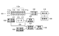
以下、本発明の実施の形態について図1,2を参照して説明する。図1は、本発明の実施の形態における圧力センサの構成を示す構成図である。また、図2は、本発明の実施の形態における圧力センサの構成を模式的に示す断面図である。 Hereinafter, embodiments of the present invention will be described with reference to FIGS. FIG. 1 is a configuration diagram showing a configuration of a pressure sensor according to an embodiment of the present invention. Further, FIG. 2 is a cross-sectional view schematically showing the configuration of the pressure sensor according to the embodiment of the present invention.
この圧力センサは、検出デバイス(センサチップ)101、圧力値出力部102、第1温度測定機構103、ヒータ(加熱機構)104、温度制御部105、第2温度測定機構106、温度差算出部107、警報出力部108を備える。また、記憶部109、補正部110を備える。
This pressure sensor includes a detection device (sensor chip) 101, a pressure
実施の形態において、センサチップ101は、よく知られた静電容量式であり、基台111,ダイアフラム112,可動電極(第1の電極)114,固定電極(第2の電極)115を備える。センサチップ101は、ダイアフラム112の変位を他の物理量(容量)の変化に変換する。
In the embodiment, the
基台111およびダイアフラム112は、例えば、サファイアやアルミナセラミックなどの耐熱耐食性を有する絶縁体から構成されている。また、受圧部となるダイアフラム112は、平面視中央に凹部を有する基台111の支持部111aによって支持されている。ダイアフラム112は、支持部111aの内側の可動領域112aにおいて、基台111の方向に変位可能とされている。可動領域112aは、例えば、平面視円形とされている。
The
可動領域112aおけるダイアフラム112と基台111との間は、容量室113とされている。容量室113はいわゆる真空とされ、基準真空室となる。この場合、実施の形態における圧力センサは、大気圧より減圧される環境における圧力(真空度)を測定する真空計である。
A
また、可動電極114は、容量室113の内部でダイアフラム112の可動領域112aに形成されている。また、固定電極115は、可動電極114と、容量室113の内部で基台111の上に可動電極114に向かい合って形成されている。なお、センサチップ101は、可動参照電極116および固定参照電極117を備える。可動参照電極116は、容量室113の内部でダイアフラム112の可動領域112aにおいて可動電極114の周囲に形成されている。固定参照電極117は、容量室113の内部で固定電極115の周囲の基台111の上に形成されている。可動参照電極116と固定参照電極117とは向かい合っている。
The
圧力値出力部102は、ダイアフラム112の変位による上記他の物理量の変化を圧力値に変換して出力する。例えば、圧力値出力部102は、ダイアフラム112の変位による容量変化を、設定されているセンサ感度を用いて圧力値に変換して出力する。
The pressure
記憶部109は、センサチップ101の所定の温度範囲における温度変化に対する圧力値の変化を示す温度特性を記憶する。例えば、センサチップ101が設定温度100℃で使用される場合、温度90℃〜110℃における圧力値の温度特性が記憶部109に記憶されている。補正部110は、第1温度測定機構103で測定されているセンサチップ101の温度に基づいて、記憶部109に記憶されている温度特性で圧力値出力部102が出力する圧力値を補正する。
The storage unit 109 stores temperature characteristics indicating changes in pressure value with respect to changes in temperature of the
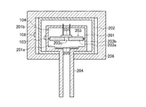
また、圧力センサは、センサチップ101を収容する内側容器201と、内側容器201を収容する外側容器202とを備える。内側容器201および外側容器202は、例えば、円筒状に形成されている。内側容器201の内部には、隔壁203が設けられている。隔壁203は、内側容器201の内部空間を圧力検出側201aとセンサチップ101が配置される素子配置側201bとに分離する。また、隔壁203の素子配置側201bに、センサチップ101が固定(接合)されて支持されている。
Further, the pressure sensor includes an
隔壁203は、台座板203aと支持隔壁203bとから構成されている。台座板203aは、センサチップ101が固定される。支持隔壁203bは、台座板203aを、内側容器201の内部側面に支持する。また、隔壁203の台座板203aには、圧力検出側201aの圧力をセンサチップ101のダイアフラムに導く圧力導入孔203cが形成されている。
The
また、内側容器201には、圧力導入管204が接続されている。圧力導入管204により、内側容器201の圧力検出側201aと、圧力測定対象となる装置内部とが連通する。圧力導入管204により、内側容器201の圧力検出側201aに測定対象の圧力が導入される。圧力導入管204の内側開口端と圧力導入孔203cとの間には、バッフル板205が設けられている。バッフル板205により、圧力導入管204より導入される流体を、センサチップ101に直接到達させずに迂回させている。
A
ここで、第1温度測定機構103は、内側容器201の素子配置側201bの温度を測定する。第1温度測定機構103は、内側容器201の素子配置側201bの外側壁面に設けられている。第1温度測定機構103により、内側容器201の温度を測定することで、センサチップ101の温度としている。
Here, the first
また、ヒータ(電熱器)104は、外側容器202の外側に壁面に設置されている。例えば、円筒状とされている外側容器202の外周面を取り巻くように、ヒータ104が設置されている。ヒータ104により外側容器202の内部を加熱する。
Further, the heater (electric heater) 104 is installed on the wall surface outside the
上述したように、外側容器202に配置されているヒータ104の外側周面に、第2温度測定機構106が接して設けられている。第2温度測定機構106は、ヒータ104の温度を測定する。例えば、第2温度測定機構106は、過昇温防止など、ヒータ104の動作を監視するために設けられている。なお、ヒータ104が設置されている外側容器202は、断熱部材206により覆われている。
As described above, the second
上述したように隔壁203により隔てられている内側容器201の圧力検出側201aは、例えば、測定対象の流体が導入される側である。これに対し、素子配置側201bは、いわゆる真空状態とされている。
As described above, the
ここで、センサチップ101の容量室113は、真空状態に気密とされていることが理想的である。しかしながら、小型なセンサチップ101の容量室113を、真空状態に気密として製造することは容易ではない。このため、センサチップ101には、容量室113と外部とを連通する連通口が設けられている。圧力センサの製造過程で、センサチップ101を設置した素子配置側201bを真空排気することで、容量室113を真空状態とする。
Here, it is ideal that the
上述したように構成されている外側容器202をヒータ104により加熱すると、この熱は、大気圧とされている外側容器202の内部の空気層を伝導し、内側容器201を加熱する。ここで、内側容器201にヒータを設けて直接加熱することも考えられる。しかしながら、直接加熱した場合、内側容器201の全体を均一に加熱することが容易ではない。これは、実際に作製した上で確認している。これに対し、実施の形態では、外側容器202を設け、内側容器201との間に気体(空気)の層を設けている。この状態で外側容器202を加熱することで、内側容器201の全体を均一に加熱することが可能となる。
When the
このようにして加熱された内側容器201では、圧力検出側201aにおける副生成物の堆積が低減される。また、加熱された内側容器201の内部では、素子配置側201bに配置されているセンサチップ101も、加熱されることになる。加熱されたセンサチップ101においては、ダイアフラム112に対する副生成物の堆積が低減される。
In the thus heated
素子配置側201bの内側容器201外側の側面に設置されている第1温度測定機構103は、内側容器201の内部温度を測定する。このようにして第1温度測定機構103で測定されている第1温度値を元に、温度制御部105は、ヒータ104の動作を制御してセンサチップ101が設定温度に加熱されるようにする。
The first
上述した構成において、本発明の実施の形態では、温度差算出部107により、第1温度測定機構103が測定した第1温度値と第2温度測定機構106が測定した第2温度値との温度差を求めるようにした。また、警報出力部108により、温度差算出部107が算出した温度差が設定範囲を外れた場合に、圧力導入管204に伝わる熱に変動が生じたことを示す警報を発令するようにした。
In the above-described configuration, in the embodiment of the present invention, the temperature
本発明では、温度差算出部107が算出した温度差が設定範囲を外れた状態を、センサチップ101に外部より伝わる熱に変動が発生しているものと判断するようにした。例えば、温度差算出部107が算出した温度差が、設定範囲より大きくなった場合、圧力導入管204からの熱の伝わりが小さくなったこと推定できる。また、一方、温度差算出部107が算出した温度差が、設定範囲より小さくなった場合は、圧力導入管204からの熱の伝わりが大きくなったことが推定できる。
In the present invention, when the temperature difference calculated by the temperature
上述したような熱伝導の変化により、圧力検出側201aの領域の温度分布がわずかに変化し、センサチップ101が持つ温度特性により圧力値出力部102の出力が変化する。この温度変化に第1温度測定機構103の温度測定結果が追従しない場合、補正部110による補正が追従せず、出力される測定値に影響を及ぼす。
Due to the change in heat conduction as described above, the temperature distribution in the region on the
ここで、圧力導入管204の温度を変化させて、第1温度測定機構103および第2温度測定機構106で測温する実験を実施した。この実験では、圧力導入管204の温度を変化させるとともに、ゼロ点の変化を確認した。
Here, an experiment was conducted in which the temperature of the
実験では、測定のレンジが10Paの圧力センサ(真空計)を用いた。ヒータ104を用いた自己加熱温度は150℃に設定した。従って、圧力センサにおいては、温度制御部105が、第1温度測定機構103による温度測定結果をもとにしたフィードバック制御で、センサチップ101が150℃となるようにヒータ104を制御する。
In the experiment, a pressure sensor (vacuum gauge) with a measurement range of 10 Pa was used. The self-heating temperature using the
また、成膜装置においては、配管部に設けられているヒータを使用し、圧力導入管204の付近を所定の温度に加熱する。配管部は、主にメインチャンバーから引き出されており、この配管部に、圧力導入管204が接続されている。配管部の内部の圧力(真空度)が、圧力センサのセンサチップ101で検出される。上述した配管部ヒータを用いた圧力導入管204の加熱状態を、圧力導入管204の温度およびセンサチップ101におけるセンサ特性が安定するまで所定時間維持した。
Further, in the film forming apparatus, a heater provided in the pipe portion is used to heat the vicinity of the
状態が安定した後、圧力センサのゼロ点調整を実施した。引き続き、圧力導入管204の温度を段階的に下げ、最終的には配管部ヒータの動作を停止した。このように圧力導入管204の温度を段階的に変化(低下)させる過程で、第1温度測定機構103および第2温度測定機構106による測温を実施した。また、上述した温度変化の過程で、温度センサのゼロ点変動を確認した。なお、配管部ヒータの動作を停止した状態では、圧力導入管204の温度は約60℃であった。
After the state became stable, the zero point adjustment of the pressure sensor was performed. Subsequently, the temperature of the
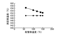
実験の結果、圧力導入管204の温度が変化すると、図3の黒丸で示すように、第1温度測定機構103による測定結果は、配管部の温度変化と一致した。一方、図3の黒四角に示すように、第2温度測定機構106の温度測定結果は、配管部の温度変化とは一致しない。また、図4に示すように、温度差算出部107による温度差の測定結果は、150℃−60℃で、約2.2℃から約6.3℃に拡大した。また、図5に示すように、上述した温度変化によるゼロ点変動(シフト)は、約0.25%F.S.であった。温度差が拡大すると、ゼロ点が正の側に変動した。
As a result of the experiment, when the temperature of the
上述した結果より、圧力導入管204の温度が変動することにより、ゼロ点が変動することが分かる。圧力導入管204の温度が変動しても、圧力センサはセンサチップ101の温度を設定されている自己加熱温度に制御するため、第1温度測定機構103の温度測定値は、変動しない。一方、第2温度測定機構106の温度測定結果は、圧力導入管204の温度の変化が反映される。従って、温度差算出部107により求められている温度差には、圧力導入管204における温度変動が反映されていることになる。
From the results described above, it can be seen that the zero point fluctuates as the temperature of the
上述したように、圧力導入管204の温度が変動すると、ゼロ点変動を引き起こしている。従って、圧力導入管204の温度の変動は、圧力センサから出力される測定値にずれが生じさせることとなる。これに対し、測定値のずれを発生させる温度変動は、温度差算出部107により求められている温度差に映されているので、温度差をもとに測定値にずれが発生している状態が判断可能である。
As described above, when the temperature of the
以上に説明したように、本発明では、自己加熱の制御用の温度を測定する第1温度測定機構の測定結果と、自己加熱用の加熱機構に接して設けられた加熱機構の温度を測定する第2温度測定機構の測定結果との差により、圧力導入管への熱伝導に変動が生じたものと判断する。この結果、本発明によれば、圧力導入管などの配管から圧力センサの検出デバイスに伝わる熱の変動が検出できるようになる。 As described above, in the present invention, the measurement result of the first temperature measuring mechanism that measures the temperature for controlling self-heating and the temperature of the heating mechanism provided in contact with the heating mechanism for self-heating are measured. Due to the difference from the measurement result of the second temperature measuring mechanism, it is determined that the heat conduction to the pressure introducing pipe fluctuates. As a result, according to the present invention, it is possible to detect the fluctuation of heat transmitted from the pipe such as the pressure introducing pipe to the detection device of the pressure sensor.
なお、本発明は以上に説明した実施の形態に限定されるものではなく、本発明の技術的思想内で、当分野において通常の知識を有する者により、多くの変形および組み合わせが実施可能であることは明白である。例えば、上述では、静電容量式の隔膜真空計を例に説明したが、これに限るものではない、ダイアフラムの変位をピエゾ抵抗の変化として検出するピエゾ抵抗式の圧力センサであっても同様である。 The present invention is not limited to the embodiments described above, and many modifications and combinations can be implemented by a person having ordinary knowledge in the field within the technical idea of the present invention. That is clear. For example, in the above description, the capacitive diaphragm vacuum gauge has been described as an example, but the present invention is not limited to this, and the same applies to a piezoresistive pressure sensor that detects displacement of the diaphragm as a change in piezoresistance. is there.
101…センサチップ(検出デバイス)、102…圧力値出力部、103…第1温度測定機構、104…ヒータ(加熱機構)、105…温度制御部、106…第2温度測定機構、107…温度差算出部、108…警報出力部、109…記憶部、110…補正部、111…基台、111a…支持部、112…ダイアフラム、112a…可動領域、113…容量室、114…可動電極(第1の電極)、115…固定電極(第2の電極)、116…可動参照電極、117…固定参照電極、201…内側容器、201a…圧力検出側、201b…素子配置側、202…外側容器、203…隔壁、203a…台座板、203b…支持隔壁、203c…圧力導入孔、204…圧力導入管、205…バッフル板、206…断熱部材。 101... Sensor chip (detection device), 102... Pressure value output unit, 103... First temperature measurement mechanism, 104... Heater (heating mechanism), 105... Temperature control unit, 106... Second temperature measurement mechanism, 107... Temperature difference Calculation unit, 108... Alarm output unit, 109... Storage unit, 110... Correction unit, 111... Base, 111a... Supporting unit, 112... Diaphragm, 112a... Movable region, 113... Volume chamber, 114... Movable electrode (first Electrode), 115... Fixed electrode (second electrode), 116... Movable reference electrode, 117... Fixed reference electrode, 201... Inner container, 201a... Pressure detection side, 201b... Element arrangement side, 202... Outer container, 203 ... partition wall, 203a... base plate, 203b... support partition wall, 203c... pressure introducing hole, 204... pressure introducing pipe, 205... baffle plate, 206... heat insulating member.
Claims (3)
前記ダイアフラムの変位による前記他の物理量の変化を圧力値に変換して出力するように構成された圧力値出力部と、
前記検出デバイスを収容する内側容器と、
前記内側容器を収容する外側容器と、
前記内側容器に接続され前記内側容器の内部に測定対象の圧力を導入するための圧力導入管と、
前記内側容器の内部に設けられ、前記内側容器の内部空間を前記圧力導入管を介して前記測定対象の圧力が導入される圧力検出側の空間と、前記圧力検出側の空間と反対側の空間で前記検出デバイスが配置される素子配置側の空間とに分離するとともに、前記素子配置側の面に前記検出デバイスが接合され、前記圧力検出側の圧力を前記検出デバイスの前記ダイアフラムに導く圧力導入孔を有する隔壁と
前記内側容器の前記素子配置側の外側壁面に設けられた第1温度測定機構と、
前記外側容器の外側に壁面に設置されて前記外側容器の内部を加熱するための加熱機構と、
前記加熱機構の動作を制御して、前記第1温度測定機構で測定される第1温度値を設定温度に近づけるように構成された温度制御部と、
前記加熱機構の温度を測定する第2温度測定機構と、
前記第1温度測定機構が測定した第1温度値と第2温度測定機構が測定した第2温度値との温度差を求めるように構成された温度差算出部と、
前記温度差算出部が算出した温度差が設定範囲を外れた場合に警報を発令するように構成された警報出力部と
を備えることを特徴とする圧力センサ。 A detection device that includes a diaphragm that is displaced by receiving pressure from a measurement target, and that converts the displacement of the diaphragm into a change in another physical quantity,
A pressure value output unit configured to convert a change in the other physical quantity due to displacement of the diaphragm into a pressure value and output the pressure value;
An inner container containing the detection device,
An outer container that houses the inner container,
A pressure introducing pipe connected to the inner container for introducing the pressure to be measured into the inner container,
A space provided inside the inner container, a space on the pressure detection side into which the pressure of the measurement target is introduced through the pressure introducing pipe, and a space on the opposite side to the space on the pressure detection side. At the element placement side where the detection device is placed, and the detection device is bonded to the element placement side surface, and the pressure introduction that guides the pressure on the pressure detection side to the diaphragm of the detection device. A partition having a hole and a first temperature measuring mechanism provided on an outer wall surface of the inner container on the element disposition side,
A heating mechanism installed on the wall surface outside the outer container for heating the inside of the outer container,
A temperature control unit configured to control the operation of the heating mechanism to bring the first temperature value measured by the first temperature measurement mechanism close to a set temperature;
A second temperature measuring mechanism for measuring the temperature of the heating mechanism;
A temperature difference calculation unit configured to obtain a temperature difference between the first temperature value measured by the first temperature measurement mechanism and the second temperature value measured by the second temperature measurement mechanism,
And a warning output unit configured to issue a warning when the temperature difference calculated by the temperature difference calculation unit is out of a set range.
前記検出デバイスは、前記ダイアフラムと離間して前記ダイアフラムを支持する基台と、前記ダイアフラムに設けられた第1の電極と、前記基台に設けられ前記第1の電極と向いあう第2の電極とを有し、
前記圧力値出力部は、前記ダイアフラムの変位による前記第1の電極と前記第2の電極との間の容量変化を前記圧力値に変換して出力することを特徴とする圧力センサ。 The pressure sensor according to claim 1,
The detection device includes a base that is spaced apart from the diaphragm and supports the diaphragm, a first electrode that is provided on the diaphragm, and a second electrode that is provided on the base and faces the first electrode. Has and
The pressure sensor, wherein the pressure value output unit converts a capacitance change between the first electrode and the second electrode due to displacement of the diaphragm into the pressure value and outputs the pressure value.
前記検出デバイスは、測定対象からの圧力を受ける受圧部となる前記ダイアフラムと反対側に真空とされた容量室を備えることを特徴とする圧力センサ。 The pressure sensor according to claim 1 or 2,
The pressure sensor, wherein the detection device includes a vacuumed volume chamber on a side opposite to the diaphragm , which serves as a pressure receiving portion that receives pressure from a measurement target.
Priority Applications (4)
| Application Number | Priority Date | Filing Date | Title |
|---|---|---|---|
| JP2017044554A JP6748006B2 (en) | 2017-03-09 | 2017-03-09 | Pressure sensor |
| KR1020180025626A KR102017300B1 (en) | 2017-03-09 | 2018-03-05 | Pressure sensor |
| CN201810191413.0A CN108572046B (en) | 2017-03-09 | 2018-03-08 | Pressure sensor |
| US15/915,367 US10585010B2 (en) | 2017-03-09 | 2018-03-08 | Pressure sensor having a temperature control unit and a temperature difference calculation unit |
Applications Claiming Priority (1)
| Application Number | Priority Date | Filing Date | Title |
|---|---|---|---|
| JP2017044554A JP6748006B2 (en) | 2017-03-09 | 2017-03-09 | Pressure sensor |
Publications (2)
| Publication Number | Publication Date |
|---|---|
| JP2018146530A JP2018146530A (en) | 2018-09-20 |
| JP6748006B2 true JP6748006B2 (en) | 2020-08-26 |
Family
ID=63446352
Family Applications (1)
| Application Number | Title | Priority Date | Filing Date |
|---|---|---|---|
| JP2017044554A Active JP6748006B2 (en) | 2017-03-09 | 2017-03-09 | Pressure sensor |
Country Status (4)
| Country | Link |
|---|---|
| US (1) | US10585010B2 (en) |
| JP (1) | JP6748006B2 (en) |
| KR (1) | KR102017300B1 (en) |
| CN (1) | CN108572046B (en) |
Families Citing this family (7)
| Publication number | Priority date | Publication date | Assignee | Title |
|---|---|---|---|---|
| JP6564358B2 (en) * | 2016-12-08 | 2019-08-21 | 長野計器株式会社 | Physical quantity measuring device |
| JP6815221B2 (en) * | 2017-02-17 | 2021-01-20 | アズビル株式会社 | Capacitive pressure sensor |
| IT201700073763A1 (en) * | 2017-07-05 | 2019-01-05 | St Microelectronics Srl | PRESSURE CAPACITIVE SENSOR FOR THE MONITORING OF BUILDING STRUCTURES, IN PARTICULAR OF CONCRETE |
| JP7092603B2 (en) * | 2018-08-03 | 2022-06-28 | 株式会社ユニバーサルエンターテインメント | Pachinko machine |
| FR3092167B1 (en) * | 2019-01-29 | 2021-10-22 | Arianegroup Sas | Sensor for measuring a first physical quantity whose measurement is influenced by a second physical quantity |
| JP7372062B2 (en) * | 2019-07-02 | 2023-10-31 | アズビル株式会社 | pressure sensor |
| JP2021162502A (en) * | 2020-04-01 | 2021-10-11 | アズビル株式会社 | Housing for pressure sensors and pressure sensor provided therewith |
Family Cites Families (17)
| Publication number | Priority date | Publication date | Assignee | Title |
|---|---|---|---|---|
| US5625152A (en) * | 1996-01-16 | 1997-04-29 | Mks Instruments, Inc. | Heated pressure transducer assembly |
| JP3404257B2 (en) * | 1997-07-11 | 2003-05-06 | 三菱電機株式会社 | Pressure sensor device |
| US6588280B1 (en) * | 2002-04-22 | 2003-07-08 | Mks Instruments, Inc. | Pressure transducer with compensation for thermal transients |
| US6701790B2 (en) * | 2002-06-13 | 2004-03-09 | Mykrolis Corporation | Temperature regulator for use with a pressure sensing device |
| JP4014006B2 (en) | 2004-06-17 | 2007-11-28 | 株式会社山武 | Pressure sensor |
| WO2008154760A1 (en) * | 2007-06-19 | 2008-12-24 | Inficon Gmbh | Vacuum measuring cell device having a heater |
| JP2009133838A (en) * | 2007-11-06 | 2009-06-18 | Canon Anelva Technix Corp | Electrostatic capacitance type diaphragm pressure sensor |
| JP2009244149A (en) * | 2008-03-31 | 2009-10-22 | Yamatake Corp | Pressure sensor |
| JP5576331B2 (en) | 2011-03-31 | 2014-08-20 | アズビル株式会社 | Pressure sensor device |
| WO2012165536A1 (en) * | 2011-05-31 | 2012-12-06 | 独立行政法人科学技術振興機構 | Method for temperature compensation in sensor, computation program for method for temperature compensation, computation processing device, and sensor |
| WO2013014803A1 (en) * | 2011-07-27 | 2013-01-31 | 株式会社トライフォース・マネジメント | Dynamic sensor |
| JP6058986B2 (en) * | 2012-11-29 | 2017-01-11 | アズビル株式会社 | Differential pressure sensor |
| JP6002016B2 (en) | 2012-11-30 | 2016-10-05 | アズビル株式会社 | Capacitive pressure sensor |
| US10130123B2 (en) * | 2013-03-15 | 2018-11-20 | Juul Labs, Inc. | Vaporizer devices with blow discrimination |
| DE102014200507A1 (en) * | 2014-01-14 | 2015-07-16 | Robert Bosch Gmbh | Micromechanical pressure sensor device and corresponding manufacturing method |
| JP6154760B2 (en) * | 2014-02-10 | 2017-06-28 | アズビル株式会社 | Capacitive pressure sensor |
| JP2016180651A (en) * | 2015-03-24 | 2016-10-13 | アズビル株式会社 | Deposit state estimation device, deposit state estimation method, and deposit state estimation system |
-
2017
- 2017-03-09 JP JP2017044554A patent/JP6748006B2/en active Active
-
2018
- 2018-03-05 KR KR1020180025626A patent/KR102017300B1/en active IP Right Grant
- 2018-03-08 CN CN201810191413.0A patent/CN108572046B/en active Active
- 2018-03-08 US US15/915,367 patent/US10585010B2/en active Active
Also Published As
| Publication number | Publication date |
|---|---|
| JP2018146530A (en) | 2018-09-20 |
| KR20180103706A (en) | 2018-09-19 |
| CN108572046A (en) | 2018-09-25 |
| KR102017300B1 (en) | 2019-09-03 |
| US10585010B2 (en) | 2020-03-10 |
| US20180259409A1 (en) | 2018-09-13 |
| CN108572046B (en) | 2020-04-24 |
Similar Documents
| Publication | Publication Date | Title |
|---|---|---|
| JP6748006B2 (en) | Pressure sensor | |
| JP5524055B2 (en) | Method for calibrating and operating a measurement cell structure | |
| KR20170101789A (en) | Method and system for detecting pressure sensor state | |
| US20180238757A1 (en) | Capacitive pressure sensor | |
| JP6093722B2 (en) | Capacitive pressure sensor | |
| WO2018225853A1 (en) | Capacitative type pressure sensor | |
| JP6748000B2 (en) | Pressure sensor | |
| CN108431571B (en) | Pressure sensor | |
| JP2013050400A (en) | Dual physical quantity sensor | |
| US20160084723A1 (en) | Pressure Sensor | |
| KR20040102631A (en) | Vacuum Meter | |
| US20160005632A1 (en) | Substrate processing apparatus and substrate processing method | |
| JP2022174404A (en) | Diaphragm gauge | |
| JP2022085260A (en) | Diaphragm vacuum gauge | |
| JP2019046286A (en) | Abnormality detection method and abnormality detector |
Legal Events
| Date | Code | Title | Description |
|---|---|---|---|
| A621 | Written request for application examination |
Free format text: JAPANESE INTERMEDIATE CODE: A621 Effective date: 20190917 |
|
| A131 | Notification of reasons for refusal |
Free format text: JAPANESE INTERMEDIATE CODE: A131 Effective date: 20200512 |
|
| A521 | Written amendment |
Free format text: JAPANESE INTERMEDIATE CODE: A523 Effective date: 20200617 |
|
| TRDD | Decision of grant or rejection written | ||
| A01 | Written decision to grant a patent or to grant a registration (utility model) |
Free format text: JAPANESE INTERMEDIATE CODE: A01 Effective date: 20200707 |
|
| A61 | First payment of annual fees (during grant procedure) |
Free format text: JAPANESE INTERMEDIATE CODE: A61 Effective date: 20200806 |
|
| R150 | Certificate of patent or registration of utility model |
Ref document number: 6748006 Country of ref document: JP Free format text: JAPANESE INTERMEDIATE CODE: R150 |