JP6747337B2 - Honeycomb structure molding die and method for manufacturing honeycomb structure molding die - Google Patents
Honeycomb structure molding die and method for manufacturing honeycomb structure molding die Download PDFInfo
- Publication number
- JP6747337B2 JP6747337B2 JP2017033408A JP2017033408A JP6747337B2 JP 6747337 B2 JP6747337 B2 JP 6747337B2 JP 2017033408 A JP2017033408 A JP 2017033408A JP 2017033408 A JP2017033408 A JP 2017033408A JP 6747337 B2 JP6747337 B2 JP 6747337B2
- Authority
- JP
- Japan
- Prior art keywords
- raw material
- material supply
- hole
- slit
- honeycomb structure
- Prior art date
- Legal status (The legal status is an assumption and is not a legal conclusion. Google has not performed a legal analysis and makes no representation as to the accuracy of the status listed.)
- Active
Links
Images


Classifications
-
- B—PERFORMING OPERATIONS; TRANSPORTING
- B28—WORKING CEMENT, CLAY, OR STONE
- B28B—SHAPING CLAY OR OTHER CERAMIC COMPOSITIONS; SHAPING SLAG; SHAPING MIXTURES CONTAINING CEMENTITIOUS MATERIAL, e.g. PLASTER
- B28B3/00—Producing shaped articles from the material by using presses; Presses specially adapted therefor
- B28B3/20—Producing shaped articles from the material by using presses; Presses specially adapted therefor wherein the material is extruded
- B28B3/26—Extrusion dies
- B28B3/269—For multi-channeled structures, e.g. honeycomb structures
-
- B—PERFORMING OPERATIONS; TRANSPORTING
- B22—CASTING; POWDER METALLURGY
- B22F—WORKING METALLIC POWDER; MANUFACTURE OF ARTICLES FROM METALLIC POWDER; MAKING METALLIC POWDER; APPARATUS OR DEVICES SPECIALLY ADAPTED FOR METALLIC POWDER
- B22F10/00—Additive manufacturing of workpieces or articles from metallic powder
- B22F10/20—Direct sintering or melting
- B22F10/28—Powder bed fusion, e.g. selective laser melting [SLM] or electron beam melting [EBM]
-
- B—PERFORMING OPERATIONS; TRANSPORTING
- B22—CASTING; POWDER METALLURGY
- B22F—WORKING METALLIC POWDER; MANUFACTURE OF ARTICLES FROM METALLIC POWDER; MAKING METALLIC POWDER; APPARATUS OR DEVICES SPECIALLY ADAPTED FOR METALLIC POWDER
- B22F5/00—Manufacture of workpieces or articles from metallic powder characterised by the special shape of the product
- B22F5/10—Manufacture of workpieces or articles from metallic powder characterised by the special shape of the product of articles with cavities or holes, not otherwise provided for in the preceding subgroups
-
- B—PERFORMING OPERATIONS; TRANSPORTING
- B23—MACHINE TOOLS; METAL-WORKING NOT OTHERWISE PROVIDED FOR
- B23P—METAL-WORKING NOT OTHERWISE PROVIDED FOR; COMBINED OPERATIONS; UNIVERSAL MACHINE TOOLS
- B23P15/00—Making specific metal objects by operations not covered by a single other subclass or a group in this subclass
- B23P15/24—Making specific metal objects by operations not covered by a single other subclass or a group in this subclass dies
- B23P15/243—Honeycomb dies
-
- B—PERFORMING OPERATIONS; TRANSPORTING
- B22—CASTING; POWDER METALLURGY
- B22F—WORKING METALLIC POWDER; MANUFACTURE OF ARTICLES FROM METALLIC POWDER; MAKING METALLIC POWDER; APPARATUS OR DEVICES SPECIALLY ADAPTED FOR METALLIC POWDER
- B22F10/00—Additive manufacturing of workpieces or articles from metallic powder
- B22F10/50—Treatment of workpieces or articles during build-up, e.g. treatments applied to fused layers during build-up
-
- B—PERFORMING OPERATIONS; TRANSPORTING
- B22—CASTING; POWDER METALLURGY
- B22F—WORKING METALLIC POWDER; MANUFACTURE OF ARTICLES FROM METALLIC POWDER; MAKING METALLIC POWDER; APPARATUS OR DEVICES SPECIALLY ADAPTED FOR METALLIC POWDER
- B22F2999/00—Aspects linked to processes or compositions used in powder metallurgy
-
- B—PERFORMING OPERATIONS; TRANSPORTING
- B28—WORKING CEMENT, CLAY, OR STONE
- B28B—SHAPING CLAY OR OTHER CERAMIC COMPOSITIONS; SHAPING SLAG; SHAPING MIXTURES CONTAINING CEMENTITIOUS MATERIAL, e.g. PLASTER
- B28B3/00—Producing shaped articles from the material by using presses; Presses specially adapted therefor
- B28B3/20—Producing shaped articles from the material by using presses; Presses specially adapted therefor wherein the material is extruded
- B28B2003/203—Producing shaped articles from the material by using presses; Presses specially adapted therefor wherein the material is extruded for multi-channelled structures, e.g. honeycomb structures
-
- B—PERFORMING OPERATIONS; TRANSPORTING
- B33—ADDITIVE MANUFACTURING TECHNOLOGY
- B33Y—ADDITIVE MANUFACTURING, i.e. MANUFACTURING OF THREE-DIMENSIONAL [3-D] OBJECTS BY ADDITIVE DEPOSITION, ADDITIVE AGGLOMERATION OR ADDITIVE LAYERING, e.g. BY 3-D PRINTING, STEREOLITHOGRAPHY OR SELECTIVE LASER SINTERING
- B33Y10/00—Processes of additive manufacturing
-
- B—PERFORMING OPERATIONS; TRANSPORTING
- B33—ADDITIVE MANUFACTURING TECHNOLOGY
- B33Y—ADDITIVE MANUFACTURING, i.e. MANUFACTURING OF THREE-DIMENSIONAL [3-D] OBJECTS BY ADDITIVE DEPOSITION, ADDITIVE AGGLOMERATION OR ADDITIVE LAYERING, e.g. BY 3-D PRINTING, STEREOLITHOGRAPHY OR SELECTIVE LASER SINTERING
- B33Y80/00—Products made by additive manufacturing
-
- Y—GENERAL TAGGING OF NEW TECHNOLOGICAL DEVELOPMENTS; GENERAL TAGGING OF CROSS-SECTIONAL TECHNOLOGIES SPANNING OVER SEVERAL SECTIONS OF THE IPC; TECHNICAL SUBJECTS COVERED BY FORMER USPC CROSS-REFERENCE ART COLLECTIONS [XRACs] AND DIGESTS
- Y02—TECHNOLOGIES OR APPLICATIONS FOR MITIGATION OR ADAPTATION AGAINST CLIMATE CHANGE
- Y02P—CLIMATE CHANGE MITIGATION TECHNOLOGIES IN THE PRODUCTION OR PROCESSING OF GOODS
- Y02P10/00—Technologies related to metal processing
- Y02P10/25—Process efficiency
Description
本発明は、ハニカム構造体の押出成形に適したハニカム構造体成形用金型と、これを製造するためのハニカム構造体成形用金型の製造方法に関する。 The present invention relates to a honeycomb structure molding die suitable for extrusion molding of a honeycomb structure, and a method for manufacturing a honeycomb structure molding die for manufacturing the same.
自動車用の排ガス浄化触媒等に用いられるハニカム構造体は、一般に、筒状外皮の内側をセル壁で区画して構成され、軸方向に延びる平行な多数のセルを有する。セル壁は、例えば、矩形セル形状に対応させた格子状であり、所望のセル密度となるように格子の大きさが設定される。ハニカム構造体は、通常、格子状のスリットと、スリットに連通する原料供給穴を設けた金型を用いて、セラミックス原料を押出成形することにより製造される。金型のスリットは、例えば、格子状の放電電極を用いた放電加工によって、原料供給穴はドリル加工によって、それぞれ形成されている。 A honeycomb structure used for an automobile exhaust gas purifying catalyst or the like is generally constituted by partitioning an inner side of a cylindrical outer shell with cell walls, and has a large number of parallel cells extending in the axial direction. The cell wall has, for example, a grid shape corresponding to a rectangular cell shape, and the size of the grid is set so as to have a desired cell density. A honeycomb structure is usually manufactured by extrusion-molding a ceramic raw material using a die having a lattice-shaped slit and a raw material supply hole communicating with the slit. The die slit is formed by, for example, electric discharge machining using a grid-shaped electric discharge electrode, and the raw material supply hole is formed by drilling.
近年、排ガス浄化触媒の早期活性化のために、ハニカム構造体のさらなる薄壁軽量化が進められている。一方、ハニカム構造体のセル壁が薄くなると、スリットへの原料の供給速度やスリットからの押出速度を均一に制御することが難しくなり、セル壁のよれや成形体の曲がりが生じやすくなる。そのため、ハニカム構造体の薄壁軽量化に限界があり、また、成形精度を高めようとすると、成形速度を低く抑える必要があり、生産性が低下する。 In recent years, in order to early activate the exhaust gas purifying catalyst, further reduction in the wall thickness of the honeycomb structure has been promoted. On the other hand, when the cell walls of the honeycomb structure become thin, it becomes difficult to uniformly control the feed rate of the raw material to the slits and the extrusion rate from the slits, and the cell walls are likely to be twisted or the molded body is easily bent. Therefore, there is a limit to the weight reduction of the thin wall of the honeycomb structure, and in order to improve the molding accuracy, it is necessary to keep the molding speed low, which lowers the productivity.
特許文献1には、材料を投入するための複数の供給穴を備えた供給セクションと、材料をハニカム構造体として吐出するための吐出開口部を備えた吐出セクションと、両セクション間に配置された遷移セクションとからなるハニカム押出しダイが開示されている。遷移セクションは、積層された複数の薄い遷移層によって形成され、各遷移層の開口部の連続によって形成される複数の導管を内蔵している。供給材料流は、導管の内部で分岐するか方向を変換し、又は断面形状を変えて、吐出セクションへ送出される。
In
特許文献1に開示されるハニカム押出しダイは、遷移セクションが、吐出セクションへの供給材料流を、流れの軸線と平行でない方向へ分配する機能を有して、押出圧を低減している。ところが、遷移セクションは、複数の薄い遷移層に設けた開口部を重ねることによって形成されるため、隣り合う開口部の間に段差が生じる。遷移層が薄く枚数が多いほど段差は緩和されるが、開口部の加工精度及び組付精度が高度に要求され、導管及び枝導管の内壁面の全体を滑らかな面とするのは難しい。そのため、例えば、セラミックス原料が通過する際に引掛かり等が生じて、隣接する領域との成形速度差が生じる要因となり、均一な押出成形ができなくなる。
In the honeycomb extrusion die disclosed in
本発明は、かかる背景に鑑みてなされたものであり、金型のスリット全体にセラミックス原料を均一に分配供給して、均一な押出成形が可能であり、薄壁軽量なハニカム構造体を成形性よく製造できるハニカム構造体成形用金型を、提供しようとするものである。 The present invention has been made in view of such a background, uniformly distributes and supplies the ceramic raw material to the entire slit of the mold, and enables uniform extrusion molding, thereby forming a thin-walled and lightweight honeycomb structure. An object of the present invention is to provide a mold for manufacturing a honeycomb structure which can be manufactured well.
本発明の一態様は、セル壁(H1)により区画された複数のセル(C)を備えるハニカム構造体(H)を押出成形するためのハニカム構造体成形用金型(1)であって、
単一の金型本体(11)と、
上記金型本体の原料供給面(12)から原料押出方向(X)に延びる複数の原料供給穴(21)を有する原料供給部(2)と、
上記複数の原料供給穴と上記金型本体内において連通すると共に、上記原料供給面と反対側の押出面(13)に開口する、格子状のスリット(31)を有するスリット部(3)と、を備え、
上記原料供給穴は、上記スリットの格子点(P)に対応して同軸的に設けられており、上記原料供給穴の上記原料押出方向の端部には、上記格子点に向けて縮径する原料絞り穴(22)と、上記原料絞り穴から外方に張り出して上記格子点に連続する上記スリットへ原料を供給案内する原料供給ガイド穴(23)が設けられると共に、
上記原料供給ガイド穴は、上記格子点に連続する上記スリットを挟んで対向する一対の面(23a、23b)の間に形成され、上記一対の面間の上記原料供給ガイド穴は、上記原料押出方向において上記格子点側へ向かうほど、上記原料絞り穴の径方向において外側へ拡がる形状を有する、ハニカム構造体成形用金型にある。
One aspect of the present invention is a honeycomb structure forming die (1) for extruding a honeycomb structure (H) including a plurality of cells (C) partitioned by cell walls (H1),
A single mold body (11),
A raw material supply part (2) having a plurality of raw material supply holes (21) extending from the raw material supply surface (12) of the mold body in the raw material extrusion direction (X);
A slit portion (3) having a lattice-like slit (31), which communicates with the plurality of raw material supply holes in the mold body and opens on an extrusion surface (13) opposite to the raw material supply surface; Equipped with
The raw material supply hole is coaxially provided corresponding to the lattice point (P) of the slit, and the end of the raw material supply hole in the raw material extrusion direction is reduced in diameter toward the lattice point. A raw material drawing hole (22) and a raw material supply guide hole (23) for feeding and guiding the raw material to the slits extending outward from the raw material drawing hole and continuing to the lattice points are provided,
The raw material supply guide hole is formed between a pair of surfaces (23a, 23b) facing each other with the slit continuous to the lattice point sandwiched therebetween, and the raw material supply guide hole between the pair of surfaces is the raw material extrusion. In the die for forming a honeycomb structure, the honeycomb structure forming die has a shape that expands outward in the radial direction of the raw material drawing hole in the direction of the grid point .
本発明の他の態様は、上記ハニカム構造体成形用金型の製造方法であって、
上記金型本体を上記原料押出方向に分割された多数の層の積層体とみなして、
台座(300)上に配置した金属粉末(301)の層にレーザ光(L)を照射し、上記原料供給穴及び上記スリットに対応する部位を除いて、上記金属粉末を溶融凝固させることにより、上記多数の層の1つを形成し、これを繰り返し行って、上記多数の層が順次積層された積層体の内部に、上記原料供給穴及び上記スリットが形成された上記金型本体を製造する、ハニカム構造体成形用金型の製造方法にある。
なお、括弧内の符号は、参考のために付したものであり、本発明はこれら符号により限定されるものではない。
Another aspect of the present invention is a method for manufacturing the above honeycomb structure molding die,
Considering the mold body as a laminate of a large number of layers divided in the raw material extrusion direction,
By irradiating the layer of the metal powder (301) arranged on the pedestal (300) with laser light (L), and melting and solidifying the metal powder except the portions corresponding to the raw material supply hole and the slit, One of the plurality of layers is formed, and this is repeated to manufacture the mold body in which the raw material supply hole and the slit are formed inside the laminate in which the plurality of layers are sequentially laminated. A method for manufacturing a honeycomb structure molding die.
The reference numerals in parentheses are provided for reference, and the present invention is not limited to these reference numerals.
上記態様のハニカム構造体成形用金型は、原料供給穴へ供給される原料を、原料押出方向に連続する原料絞り穴において縮径しながら、スリットの格子点へ送り出す。同時に、原料絞り穴の外周側の原料を、外方へ張り出す原料供給ガイド穴へ案内し、格子点に連続するスリットへ供給する。これにより、原料供給部を通過した段階で、原料がスリットのほぼ全体に分配供給されるので、スリット部において成形速度差が生じるのが抑制されて、均一な押出成形が可能になる。 The honeycomb structure forming die of the above aspect sends out the raw material supplied to the raw material supply hole to the lattice points of the slit while reducing the diameter in the raw material squeezing hole continuous in the raw material extrusion direction. At the same time, the raw material on the outer peripheral side of the raw material squeezing hole is guided to the raw material supply guide hole that projects outward, and is supplied to the slits continuous to the lattice points. As a result, since the raw material is distributed and supplied to almost the entire slit when the raw material has passed through the raw material supply section, it is possible to suppress the difference in the molding speed in the slit section, and to perform uniform extrusion molding.
このようなハニカム構造体成形用金型は、他の態様の製造方法によって、金属粉末を溶融凝固させた多数の層の積層体として構成することができる。そして、積層体の内部に形成される原料供給穴及びスリットの表面を、滑らかな連続面とすることができ、原料供給穴と原料絞り穴、原料供給ガイド穴との接続表面も、滑らかに形成することができる。したがって、原料の流動性が向上するので、成形速度を高めることができ、生産性が向上する。 Such a honeycomb structure forming die can be formed as a laminate of a large number of layers obtained by melting and solidifying a metal powder by a manufacturing method of another aspect. The surface of the raw material supply hole and the slit formed inside the laminated body can be made into a smooth continuous surface, and the connection surface between the raw material supply hole, the raw material squeezing hole, and the raw material supply guide hole is also smoothly formed. can do. Therefore, the fluidity of the raw material is improved, the molding speed can be increased, and the productivity is improved.
よって、金型のスリット全体にセラミックス原料を均一に分配供給して、均一な押出成形が可能であり、薄壁軽量なハニカム構造体を成形性よく製造できるハニカム構造体成形用金型を、提供することができる。 Therefore, a honeycomb structure molding die is provided which can uniformly extrude and supply the ceramic raw material throughout the slits of the die and can uniformly extrude the honeycomb structure and can manufacture a thin-walled and lightweight honeycomb structure with good formability. can do.
(実施形態1)
次に、ハニカム構造体成形用金型とハニカム構造体成形用金型の製造方法の実施形態について、図面を参照しながら説明する。ハニカム構造体成形用金型(以下、金型と略称する。)は、例えば、自動車用の排ガス浄化触媒等に使用されるセラミックス製のハニカム構造体を、セラミックス原料の押出成形により製造するために用いられる。
(Embodiment 1)
Next, an embodiment of a honeycomb structure forming die and a method for manufacturing the honeycomb structure forming die will be described with reference to the drawings. A honeycomb structure forming die (hereinafter, abbreviated as a die) is used, for example, for manufacturing a ceramic honeycomb structure used for an exhaust gas purifying catalyst for automobiles by extrusion forming a ceramic raw material. Used.
図1〜図3に示されるように、本形態の金型1は、単一の金型本体11と、金型本体11の原料供給面12側に設けられる原料供給部2と、原料供給面12と反対側の押出面13側に設けられるスリット部3とを備える。原料供給部2は、原料供給穴21と、原料供給穴21の原料押出方向Xの端部に設けられる、原料絞り穴22及び原料供給ガイド穴23を有している。原料供給穴21は、スリット部3に設けられる格子状のスリット31と、金型本体11内において連通している。原料絞り穴22は、スリット31の格子点Pに向けて縮径し、原料供給ガイド穴2は、原料絞り穴22から外方に張り出して格子点Pに連続するスリットへ原料を供給案内する。
As shown in FIGS. 1 to 3, the
金型本体11は、全体が矩形の外形を有する単一の板状体で(例えば、図2参照)、その板厚方向を、原料押出方向Xとしている。原料供給部2とスリット部3は、板面の中央部に配置されており、その外形及びスリット形状は、ハニカム構造体の外形及びセル形状に対応している。金型本体11は、原料供給部2とスリット部3とが一体的に設けられており、例えば、後述するように3Dプリンタを用いて製造することができる。
The
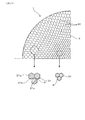
図4に示されるように、ハニカム構造体Hは、例えば、円柱状で、円筒外皮内をハニカム状のセル壁H1にて多数のセルCに区画して構成されている。セルCの形状や大きさは、任意に選択することができる。本形態では、一例として、セルCの形状を正方形とし、全領域で同一の大きさに設定している。セルCの形状を、三角形以上の多角形又は複数の形状の組み合わせとしたり、セルCの大きさを、周方向に分割した複数の領域ごとに変更して、例えば、内周側と外周側とで異なるセル密度としたりすることもできる。 As shown in FIG. 4, the honeycomb structure H has, for example, a columnar shape, and is configured by partitioning the inside of a cylindrical outer shell into a large number of cells C by honeycomb-shaped cell walls H1. The shape and size of the cell C can be arbitrarily selected. In the present embodiment, as an example, the shape of the cell C is a square, and the same size is set in all areas. The shape of the cell C may be a polygon of a triangle or more or a combination of a plurality of shapes, or the size of the cell C may be changed for each of a plurality of regions divided in the circumferential direction, and for example, the inner circumference side and the outer circumference side may be changed. Different cell densities can be obtained with.
図1、図3において、原料供給部2は、一端側(すなわち、図の下端側)が原料供給面12に開口し、原料押出方向Xに延びる多数の原料供給穴21を有している。多数の原料供給穴21は、同一形状で、互いに平行かつ等間隔にて配設されて、スリット部3の所定位置へセラミックス原料を均等に供給可能としている。原料供給穴21は、原料押出方向Xの両端部を除いて一定径の円形穴となっており、この円形穴の流路長を長くすることで金型本体11の剛性が向上し、成形圧力を増加させたときの金型本体11の変形を低減できる。原料供給穴21は滑らかな内表面を有し、セラミックス原料との摩擦係数が低いほど、成形速度が向上し、内表面の摩耗も少なくなるので好ましい。
In FIG. 1 and FIG. 3, the raw
原料供給穴21は、原料供給面12に開口する端部を、開口端縁部へ向けて拡径する(すなわち、原料押出方向Xへ向けて縮径する)原料供給テーパ穴24としている。原料供給テーパ穴24は、原料供給穴21を構成する円筒状の内周壁と滑らかに連続するテーパ壁にて囲まれており、原料供給面12から導入されるセラミックス原料を、原料供給穴21へ送出する。原料供給テーパ穴24を設けることで、セラミックス原料と面直に当る原料供給面12の面積を低減させ、かつ穴壁面との摩擦による損失係数を低減することができるので、金型本体11の変形を低減し成形速度を向上させることができる。
The raw
原料供給テーパ穴24の流路長やテーパ角度は、特に制限されず、金型本体11の剛性や成形速度等が所望の範囲となるように、適宜設定することができる。金型本体11とセラミックス原料の摩擦係数が十分小さく、成形時の変形を抑制しつつ成形速度を確保できる場合には、原料供給テーパ穴24を設けない構成とすることもできる。
The flow path length and the taper angle of the raw material
原料供給穴21は、原料供給面12と反対側の端部(すなわち、原料押出方向Xの端部)を、スリット部3側へ向けて(すなわち、原料押出方向Xへ向けて)縮径する、テーパ状の原料絞り穴22としている。原料絞り穴22の縮径側の端部は、スリット31の格子点Pに開口している。また、原料絞り穴22の外側には、複数個所に、格子点Pに隣接するスリット31へのガイドとなる原料供給ガイド穴23が一体的に設けられる。原料供給ガイド穴23は、ここでは、縦方向(すなわち、原料押出方向X)の断面形状が逆三角形の偏平穴であり、原料絞り穴22を挟んで両側に対称配置される。逆三角形の内側の一辺は、原料絞り穴22のテーパ状の内壁面に開口し、原料絞り穴22と互いに連通して、セラミックス原料を外方へ案内する原料導出用の開口部231となる。逆三角形のスリット部3側の一辺は、スリット31へ開口する原料分配用の開口部232となる。
The raw
スリット部3は、正方形のセルCに対応する四角格子状のスリット31にて構成される。スリット31の形状は、原料押出方向Xにおいて一定であり、ハニカム構造体Hの最終形状を決定する。例えば、スリット31の格子間隔やスリット幅は、セルCのピッチやセル壁H1の厚さに応じて設定される。スリット31の高さは、特に制限されず、例えば、スリット31の格子間隔と同等程度に設定することができる。
The
図5、図6に詳細形状例を示すように、原料供給穴21は、例えば、スリット31の四角格子の格子点Pに対して、縦方向及び横方向共に1つおきとなるように配置されている。原料供給穴21は、原料絞り穴22が格子点Pに開口し、一定径の原料供給穴21及び原料供給テーパ穴24が同心状に位置している。原料供給テーパ穴24の外径は、例えば、四角格子の対角線長と同等程度ないしそれ以下とすることができ、外径が大きくなるほど、原料供給テーパ穴24が近接配置される。これにより、セラミックス原料を効率よく供給して、原料供給テーパ穴24に流入する際の損失係数を低減し、金型1の変形を抑制して、成形速度を高めることができる。
As shown in the detailed shape examples in FIGS. 5 and 6, the raw material supply holes 21 are arranged, for example, at every other vertical and horizontal directions with respect to the grid point P of the square grid of the
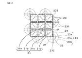
また、原料絞り穴22に連通して、外周の4箇所から外方に突出する原料供給ガイド穴23が設けられる。4箇所の原料供給ガイド穴23は、それぞれ、格子点Pに連続する4つのスリット溝31a、31b、31c、31dに沿って延び、格子点Pの周りに対称に配置される。各原料供給ガイド穴23は、各スリット溝31a、31b、31c、31dを挟んで対向する、逆三角形状の一対の面23a、23bとこれら両面を接続する傾斜面23cにて構成され、内部に偏平穴状の原料供給ガイド穴23を形成する。原料供給ガイド穴23は、原料押出方向Xに延びる開口部231にて、原料絞り穴22に開口し、原料押出方向Xの端部へ向かうほど、径方向外方へ拡がって、開口部232にてスリット31に開口する。
In addition, raw material supply guide holes 23 that communicate with the raw material throttle holes 22 and project outward from four locations on the outer periphery are provided. The four raw material supply guide holes 23 extend along the four
原料供給ガイド穴23の高さは、原料絞り穴22の高さと同等であり、傾斜面23cの対向位置に形成される開口部231は、原料供給ガイド穴23の全長にわたって、原料絞り穴22に開口している。一対の面23a、23bは、例えば、互いに平行に配設されて、一対の面23a、23b間にスリット状の穴を形成する。このスリット穴の幅は、スリット31の幅と同等かわずかに大きい。スリット31に接続される原料押出方向X側の端部において、原料供給ガイド穴23の延出端である開口部232の最外縁部は、隣接する格子点Pの近傍まで延びている。
The height of the raw material
原料供給ガイド穴23は、例えば、原料供給穴21側からスリット31側へ滑らかにスリット穴の幅が拡大する形状とすることもでき、成形抵抗がより少なくなる。原料供給ガイド穴23は、スリット31のスリット幅が、例えば、領域ごとにそれぞれ異なる場合に、それに応じてスリット穴の幅が異なるように構成することができる。このようにすることで、スリット31の各領域への材料供給を一定にすることができ、精度の高い成形体を得ることができる。原料供給穴21に続く原料絞り穴22に対しても、対応する格子点Pにおけるスリット幅に応じて、格子点Pにおける開口部の大きさが異なるように構成することができ、同様の効果が得られる。
The raw material
このとき、図7に原料供給部2及びスリット部3の内部形状(すなわち、原料供給部2及びスリット部3を通過するセラミックス原料の立体形状)を示すように、原料供給テーパ穴24から原料供給穴21を経て、原料絞り穴22に導入されるセラミックス原料の一部は、原料供給ガイド穴23に案内されて、徐々に側方へ拡がる。すなわち、原料絞り穴22が、スリット31の格子点Pへ向けて縮径するのに伴い、余剰のセラミックス原料が、原料供給ガイド穴23の開口部231から外方へ移送され、格子点Pを取り囲むスリット31へ向けて案内される。したがって、スリット部3への開口部232に至るまでの間にセラミックス原料を分配し、スリット31のほぼ全体に均一供給することができるので、スリット31の形状に押出成形されたハニカム構造体Hが容易に得られる。
At this time, as shown in FIG. 7 showing the internal shapes of the raw
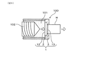
図8に示されるように、本形態の金型1を用いて、ハニカム構造体Hを押出成形する場合には、押出成形装置100の押出側端面部に、スリット部3が外側となるように金型1を設置し、セラミックス原料101を供給する。押出成形装置100内には、金型1の原料供給面12と対向する供給側端面部に、スクリュー102が設置されており、粘土状のセラミックス原料101を、金型1の原料押出方向X(すなわち、図中に矢印で示す方向)に供給する。これにより、スリット部3を通過したセラミックス原料101が押出面13から、ハニカム構造体Hとして押し出される。セラミックス原料101としては、例えば、焼成後にコージェライト、SiC等を生成するセラミックス原料を採用することができる。
As shown in FIG. 8, when the honeycomb structure H is extrusion-molded by using the
図9に示されるように、押出成形時には、金型1の原料供給面12に高い成形圧力が加わるので、セラミックス原料が通過する中央部が原料押出方向Xに突出するように変形しやすくなる。そのため、従来は、成形圧力を低く抑えて変形を抑制する必要があったが、本形態の金型1は、原料供給部2からスリット部3へのセラミックス原料の流れを高度に制御し、金型本体11の変形を抑制しつつ成形圧力を増加させることが可能となる。この押出成形時のセラミックス原料の流れについて、次に説明する。
As shown in FIG. 9, during extrusion molding, a high molding pressure is applied to the raw
図10、図11に示されるように、原料供給部2は、原料供給面12に開口する原料供給テーパ穴24を有するので、セラミックス原料が面直に当たる面積が小さくなる。また、原料供給テーパ穴24に導入されるセラミックス原料は、テーパ状の内壁面に沿って原料供給穴21へ送出され、速やかに原料供給穴21を通過して原料絞り穴22へ向かう。セラミックス原料は、原料絞り穴22のテーパ状の内壁面に沿って、徐々に絞られながらスリット31の格子点Pへ向かうと共に、外周側の一部は、内壁面の4箇所に開口する原料供給ガイド穴23から、外方へ導出される。原料供給ガイド穴23は、平坦な一対の面23a、23b間に流入するセラミックス原料の流れを、傾斜面23cに沿って徐々に外側へ案内する。
As shown in FIGS. 10 and 11, since the raw
原料供給ガイド穴23の、原料押出方向Xの端部は、隣り合う格子点P間のスリット31(すなわち、スリット溝31a〜31d)に開口しており、原料絞り穴22及び原料供給ガイド穴23を通過してセラミックス原料は、速やかに対向するスリット31へ流入する。原料絞り穴22が配置されていない格子点Pにおいても、隣接する4箇所の原料供給ガイド穴23を通過したセラミックス原料が、速やかに流入して結合し、原料押出方向Xに向きを変えて、スリット31へ流入する。
An end portion of the raw material
ここで、原料供給部2の各穴の内壁面は、いずれも滑らかな曲面又は平面であり、原料供給テーパ穴24と原料供給穴21、原料供給穴21と原料絞り穴22及び原料供給ガイド穴23の内壁面は、それぞれ滑らかに接続する連続面となっており段差等を有しない。そのため、原料供給部2内におけるセラミックス原料の流れは滑らかであり、引っ掛かりや滞りが生じることはない。このようにして、原料供給部2を通過する間に、スリット31の形状に対応させてセラミックス原料が分配され、遅滞なくスリット部3の全体へ供給される。スリット部3に達したセラミックス原料は、そのままスリット31から均等に押し出される。したがって、成形性が大きく向上し、金型1の変形を抑制しながら、成形速度を向上させることができるので、品質向上と生産性を両立させることができる。
Here, the inner wall surface of each hole of the raw
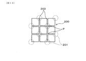
これに対して、図12、図13に示される従来の金型200のように、一定径の原料供給穴201が、テーパ状の端部202を介して、スリット203の格子点Pに接続する構成では、セラミックス原料の流れが均一とならない。ここでは、スリット203の格子点Pに1つおきに原料供給穴201が接続しており、丸穴状の端部202から格子状のスリット203の全体に、セラミックス原料を均等に分配することは難しい。そのため、スリット203の原料押出方向Xの長さを十分に長くし、あるいは成形速度を遅くする必要がある。
On the other hand, like the
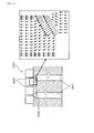
図14、図15に示されるように、本形態の金型1と従来の金型200との効果の違いは、セラミックス原料の流れをシミュレーションにより比較した場合に明らかである。図14において、本形態の金型1では、原料絞り穴22及び原料供給ガイド穴23から、スリット31へ向かうセラミックス原料の流れが、ほぼ均一であり、流れ方向や速度が大きく変化していないことが分かる。これに対して、図15において、従来の金型200では、原料供給穴201からテーパ状の端部202に向けて、一旦内向きに流れが変化した後、外向きに大きく変化している。また、流れの速度は内側で大きく、外側では小さくなっており、均一な流れを形成していない。
As shown in FIGS. 14 and 15, the difference in effect between the
図16に示すように、本形態の金型1は、例えば、3Dプリンタを用いて金属粉末をレーザ焼結させる三次元金属積層造形方式により製造することができる。図16の工程(1)〜工程(3)は、3Dプリンタを用いた金型1の製造工程の一例を、模式的に示しており、以下、金型1の原料供給部2の積層造形後に、スリット部3を積層する工程として説明する。3Dプリンタは、容器状の装置の底面となる可動式の台座300を有しており、工程(1)の粉末敷工程において、台座300の上面に、三次元造形された原料供給部2が配置され、その全体を覆って、金属粉末301が充填されている。金属粉末301としては、例えば、ステンレス鋼等の鋼材の微細粉末が用いられる。
As shown in FIG. 16, the
図16の工程(2)はレーザ加工工程であり、レーザ照射装置302を用いて、金属粉末301の所望の部位にレーザ光を走査し、溶融凝固させる。1回のレーザ照射により形成される層の厚さは、例えば、0.05mm程度であり、溶融凝固後に、工程(1)の粉末敷工程を再び行う。金型1は、予め原料押出方向Xについて、三次元データに基づく解析を行い、各層の形状に合わせてレーザ照射装置302を制御する。この工程(1)〜工程(2)を、例えば、10回繰り返した後、台座300を、積層厚さ分だけ加工させ(例えば、0.5mm)、工程(3)の切削加工工程を行う。工程(3)において、切削工具303を用いて、切削加工を行った後、工程(1)〜工程(3)を繰り返して、金型1となる金属積層体を得ることができる。
Step (2) in FIG. 16 is a laser processing step, in which a desired portion of the
図17に示すように、本形態の金型1は、例えば、スリット部3におけるスリット幅が0.08mm、格子点P間の距離が0.9mmであり、これらは、それぞれハニカム構造体Hのセル壁厚、セルピッチに対応する。また、原料押出方向Xにおいて、例えば、金型本体11の全長が40mm、原料絞り穴22の長さが10mm、スリット31の長さが2.5mmであり、原料供給穴21の直径は0.85mm、原料供給テーパ穴24の直径は1.2mm、原料供給テーパ穴24のテーパ角度は60度とすることができる。金型1は、このような微小な穴径の原料供給部2から微細なスリット部3へセラミックス原料を均一に供給して、薄壁のハニカム構造体Hを成形性よく製造することができる。
As shown in FIG. 17, the
(実施形態2)
上記実施形態1に示した金型1は、原料供給部2の原料供給穴21を、スリット部3のスリット31の格子点Pに対して、縦横方向に1つおきに配置したが、必ずしもこれに限らず、任意に変更することができる。図18に示すように、本形態では、例えば、原料供給穴21を、スリット31の全ての格子点Pに対して配置している。この場合も、原料供給穴21に連続する原料供給テーパ穴24が原料供給面12に開口し、原料絞り穴22がスリット31の格子点Pに開口すると共に、原料絞り穴22の外方に原料供給ガイド穴23が一体に設けられる構成は、同様である。
(Embodiment 2)
In the
原料供給穴21や原料供給テーパ穴24の穴径、原料押出方向Xの長さ等は、金型1の剛性が確保できるように、適宜設定することができる。このような構成の金型1も、上述した3Dプリンタを用いて、精度よく製造することができる。それ以外の金型1の構造、材質その他は、実施形態1と同様であり、説明を省略する。このような構成の金型1によっても、原料供給を均一に行って、薄壁のハニカム構造体Hを成形性よく製造することができる。
なお、実施形態2以降において用いた符号のうち、既出の実施形態において用いた符号と同一のものは、特に示さない限り、既出の実施形態におけるものと同様の構成要素等を表す。
The diameter of the raw
In addition, among the reference numerals used in the second and subsequent embodiments, the same reference numerals as those used in the already-described embodiments represent the same components and the like as those in the already-described embodiments, unless otherwise specified.
(実施形態3)
上記実施形態1、2においては、スリット部3のスリット31の形状を、四角格子状としたが、必ずしもこれに限らず、任意に変更することができる。図19に示すように、本形態では、例えば、六角形格子状のスリット31として、スリット31の格子点Pに連続する3つのスリット溝31a、31b、31cを有する形状とする。六角形格子の大きさは、スリット部3の全体で一定としている。
(Embodiment 3)
In
この場合も、原料供給穴21に連続する原料供給テーパ穴24が原料供給面12に開口し、原料絞り穴22がスリット31の格子点Pに開口すると共に、原料絞り穴22の外方に原料供給ガイド穴23が一体に設けられる構成は、同様である。ただし、上記実施形態1、2では、原料供給ガイド穴23を四角格子状のスリット31に対応させて、原料絞り穴22の外側の4箇所に設けたが、本形態では、3つのスリット溝31a、31b、31cに対応させる。すなわち、原料絞り穴22の外側の3箇所に、原料供給ガイド穴23が均等に配置されて放射状に外方へ延び、3つのスリット溝31a、31b、31cにセラミックス原料を均一供給することができる。
Also in this case, the raw material
このような構成の金型1によっても、原料供給を均一に行って、薄壁のハニカム構造体Hを成形性よく製造することができる。それ以外の金型1の構造、材質その他は、実施形態1と同様であり、説明を省略する。
Also with the
(実施形態4)
上記実施形態1〜3においては、スリット部3のスリット31の形状を、四角格子又は六角格子状の同一形状としたが、必ずしもこれに限らず、部分的に変更することもできる。本形態では、図20に示すように、上記実施形態3におけるスリット部3のスリット31の大きさを、内外周で変更しており、例えば、内周部の六角格子を小さくし、外周側ほど六角格子がより大きくなるように設定している。このとき、図示するように、スリット31の六角格子が徐々に大きくなり、外周側における六角格子が正六角形から変形した形状となってもよい。
(Embodiment 4)
In
この場合も、原料供給穴21に連続する原料供給テーパ穴24が原料供給面12に開口し、原料絞り穴22がスリット31の格子点Pに開口すると共に、原料絞り穴22の外方に原料供給ガイド穴23が一体に設けられる構成は、実施形態3と同様である。このような構成の金型1によっても、原料供給を均一に行って、薄壁のハニカム構造体Hを成形性よく製造することができる。また、スリット31の大きさを、内外周で変更可能とすることで、所望のハニカム構造体Hの形状を容易に実現することができる。
Also in this case, the raw material
(実施形態5)
図21に示すように、上記実施形態1〜4の構成の金型1において、さらに、原料供給部2に水を供給する水供給装置4を付設することもできる。水供給装置4は、例えば、金型本体11の外周部内に設けられた水貯留部41と、水貯留部41と原料供給穴21とを接続する複数の水路42とを有している。各水路42の両端は、それぞれ水貯留部41と原料供給穴21の1つに接続し、原料供給穴21の内周側面に開口する導水口43から、原料供給穴21内に水が供給されるようになっている。水貯留部41は、図示しない金型本体11外部の水供給路に連通している。
(Embodiment 5)
As shown in FIG. 21, in the
上記構成によれば、押出成形時に、各水路42から原料供給穴21の内部に適量の水が供給されて、セラミックス原料と金型1との摩擦係数を大幅に低減することができる。これにより、同じ成形速度にて比較すると、水供給を行わない場合に比べて成形圧力を低減させる効果が得られる。
According to the above configuration, an appropriate amount of water is supplied from each
複数の水路42は、金型本体11の原料供給穴21が形成されない部位を通過して、対応する原料供給穴21に開口するように配置されていればよく、水路42の形状や原料供給穴21への開口位置は、適宜設定することができる。このような水供給装置4を付設した金型1も、上述した3Dプリンタを用いた方法により製造することができる。
It suffices that the plurality of
上記実施形態では、ハニカム構造体Hを円柱状とした場合を示したが、ハニカム構造体Hの外形は、円形以外の形状、例えば、楕円形、レーストラック形状等とすることもできる。これら形状に対応するように、金型1の原料供給部2、スリット部3の外形も適宜変更される。同様に、ハニカム構造体HのセルCの形状や壁厚その他に対応するように、原料供給部2の原料供給穴21、スリット部3のスリット31の形状等も適宜変更することができる。
In the above embodiment, the case where the honeycomb structure H has a cylindrical shape has been described, but the outer shape of the honeycomb structure H may be a shape other than a circle, for example, an ellipse, a racetrack shape, or the like. The outer shapes of the raw
このような金型1を用いて製造されたハニカム構造体Hは、例えば、自動車用の排ガス浄化触媒等において、触媒を担持させる担体として用いることができる。また、金型1とその製造方法は、上記各実施形態により限定されるものではなく、その要旨を逸脱しない範囲において種々の実施形態に適用することが可能である。
The honeycomb structure H manufactured using such a
1 ハニカム構造体成形用金型
11 金型本体
12 原料供給面
13 押出面
2 原料供給部
21 原料供給穴
22 原料絞り穴
23 原料供給ガイド穴
3 スリット部
31 スリット
DESCRIPTION OF
Claims (6)
単一の金型本体(11)と、
上記金型本体の原料供給面(12)から原料押出方向(X)に延びる複数の原料供給穴(21)を有する原料供給部(2)と、
上記複数の原料供給穴と上記金型本体内において連通すると共に、上記原料供給面と反対側の押出面(13)に開口する、格子状のスリット(31)を有するスリット部(3)と、を備え、
上記原料供給穴は、上記スリットの格子点(P)に対応して同軸的に設けられており、上記原料供給穴の上記原料押出方向の端部には、上記格子点に向けて縮径する原料絞り穴(22)と、上記原料絞り穴から外方に張り出して上記格子点に連続する上記スリットへ原料を供給案内する原料供給ガイド穴(23)が設けられると共に、
上記原料供給ガイド穴は、上記格子点に連続する上記スリットを挟んで対向する一対の面(23a、23b)の間に形成され、上記一対の面間の上記原料供給ガイド穴は、上記原料押出方向において上記格子点側へ向かうほど、上記原料絞り穴の径方向において外側へ拡がる形状を有する、ハニカム構造体成形用金型。 A honeycomb structure molding die (1) for extruding a honeycomb structure (H) comprising a plurality of cells (C) partitioned by cell walls (H1),
A single mold body (11),
A raw material supply part (2) having a plurality of raw material supply holes (21) extending from the raw material supply surface (12) of the mold body in the raw material extrusion direction (X);
A slit portion (3) having a lattice-like slit (31), which communicates with the plurality of raw material supply holes in the mold body, and which is open to the extrusion surface (13) opposite to the raw material supply surface; Equipped with
The raw material supply hole is coaxially provided corresponding to the lattice point (P) of the slit, and the end of the raw material supply hole in the raw material extrusion direction is reduced in diameter toward the lattice point. A raw material drawing hole (22) and a raw material supply guide hole (23) for feeding and guiding the raw material to the slits extending outward from the raw material drawing hole and continuing to the lattice points are provided,
The raw material supply guide hole is formed between a pair of surfaces (23a, 23b) facing each other with the slit continuous to the lattice point sandwiched therebetween, and the raw material supply guide hole between the pair of surfaces is the raw material extrusion. A die for forming a honeycomb structure, which has a shape that expands outward in the radial direction of the raw material drawing hole in the direction of the grid point .
上記金型本体を上記原料押出方向に分割された多数の層の積層体とみなして、
台座(300)上に配置した金属粉末(301)の層にレーザ光(L)を照射し、上記原料供給穴及び上記スリットに対応する部位を除いて、上記金属粉末を溶融凝固させることにより、上記多数の層の1つを形成し、これを繰り返し行って、上記多数の層が順次積層された積層体の内部に、上記原料供給穴及び上記スリットが形成された上記金型本体を製造する、ハニカム構造体成形用金型の製造方法。 A method for manufacturing a honeycomb structure molding die according to any one of claims 1 to 5,
Considering the mold body as a laminate of a large number of layers divided in the raw material extrusion direction,
By irradiating the layer of the metal powder (301) arranged on the pedestal (300) with a laser beam (L), and melting and solidifying the metal powder except the portions corresponding to the raw material supply hole and the slit, One of the plurality of layers is formed, and this is repeated to manufacture the mold body in which the raw material supply hole and the slit are formed inside the laminate in which the plurality of layers are sequentially laminated. A method for manufacturing a die for forming a honeycomb structure.
Priority Applications (4)
| Application Number | Priority Date | Filing Date | Title |
|---|---|---|---|
| JP2017033408A JP6747337B2 (en) | 2017-02-24 | 2017-02-24 | Honeycomb structure molding die and method for manufacturing honeycomb structure molding die |
| CN201880012891.9A CN110325336A (en) | 2017-02-24 | 2018-01-16 | The manufacturing method of honeycomb structure forming metal mold and honeycomb structure forming metal mold |
| PCT/JP2018/000926 WO2018155002A1 (en) | 2017-02-24 | 2018-01-16 | Honeycomb structure molding mold and method for manufacturing honeycomb structure molding mold |
| US16/544,430 US11059200B2 (en) | 2017-02-24 | 2019-08-19 | Honeycomb structure forming die and method of manufacturing honeycomb structure forming die |
Applications Claiming Priority (1)
| Application Number | Priority Date | Filing Date | Title |
|---|---|---|---|
| JP2017033408A JP6747337B2 (en) | 2017-02-24 | 2017-02-24 | Honeycomb structure molding die and method for manufacturing honeycomb structure molding die |
Publications (3)
| Publication Number | Publication Date |
|---|---|
| JP2018138348A JP2018138348A (en) | 2018-09-06 |
| JP2018138348A5 JP2018138348A5 (en) | 2019-04-11 |
| JP6747337B2 true JP6747337B2 (en) | 2020-08-26 |
Family
ID=63252579
Family Applications (1)
| Application Number | Title | Priority Date | Filing Date |
|---|---|---|---|
| JP2017033408A Active JP6747337B2 (en) | 2017-02-24 | 2017-02-24 | Honeycomb structure molding die and method for manufacturing honeycomb structure molding die |
Country Status (4)
| Country | Link |
|---|---|
| US (1) | US11059200B2 (en) |
| JP (1) | JP6747337B2 (en) |
| CN (1) | CN110325336A (en) |
| WO (1) | WO2018155002A1 (en) |
Families Citing this family (6)
| Publication number | Priority date | Publication date | Assignee | Title |
|---|---|---|---|---|
| EP3569311A1 (en) * | 2018-05-18 | 2019-11-20 | Basf Se | Matrix with metal printed parts for the extrusion of shaped bodies |
| CN112092152A (en) * | 2020-09-16 | 2020-12-18 | 杭州天佳建材科技有限公司 | Honeycomb ceramic production and preparation mold and production and preparation process |
| WO2022234492A1 (en) | 2021-05-04 | 2022-11-10 | Federal-Mogul Ignition Gmbh | Spark plug electrode and method of manufacturing the same |
| US11901705B2 (en) | 2021-07-22 | 2024-02-13 | Federal-Mogul Ignition Gmbh | Electrode tip assembly for a spark plug and method of manufacturing the same |
| US11621544B1 (en) | 2022-01-14 | 2023-04-04 | Federal-Mogul Ignition Gmbh | Spark plug electrode and method of manufacturing the same |
| DE102023107904A1 (en) | 2022-03-29 | 2023-10-05 | Federal-Mogul Ignition Gmbh | SPARK PLUG, SPARK PLUG ELECTRODE AND METHOD FOR PRODUCING THE SAME |
Family Cites Families (16)
| Publication number | Priority date | Publication date | Assignee | Title |
|---|---|---|---|---|
| US4731010A (en) * | 1987-05-22 | 1988-03-15 | Corning Glass Works | Extrusion die for forming thin-walled honeycomb structures |
| US4884960A (en) * | 1988-05-06 | 1989-12-05 | Allied-Signal Inc. | Die for extruding and wash coating |
| US5171503A (en) | 1988-08-29 | 1992-12-15 | Corning Incorporated | Method of extruding thin-walled honeycomb structures |
| US5066215A (en) * | 1988-08-29 | 1991-11-19 | Corning Incorporated | Extrusion die for forming thin-walled honeycomb structures |
| JP3121407B2 (en) * | 1991-11-14 | 2000-12-25 | イビデン株式会社 | Extrusion die for honeycomb structure |
| JPH08336819A (en) * | 1995-06-09 | 1996-12-24 | Babcock Hitachi Kk | Molding method for fiber-containing honeycomb molding and mouthpiece for molding |
| US5702659A (en) * | 1995-11-30 | 1997-12-30 | Corning Incorporated | Honeycomb extrusion die and methods |
| JP2002110275A (en) * | 2000-10-04 | 2002-04-12 | Yazaki Corp | Male terminal |
| JP3856654B2 (en) * | 2001-02-23 | 2006-12-13 | 松下電工株式会社 | Manufacturing method of three-dimensional shaped object |
| JP4426400B2 (en) * | 2004-08-11 | 2010-03-03 | 日本碍子株式会社 | Die for forming honeycomb structure and method for manufacturing the same |
| US6991450B1 (en) * | 2004-08-31 | 2006-01-31 | Corning Incorporated | Open cavity extrusion dies |
| WO2009119422A1 (en) * | 2008-03-28 | 2009-10-01 | 日立金属株式会社 | Die for forming ceramic honeycomb structure |
| KR101546997B1 (en) * | 2008-09-29 | 2015-08-24 | 스트랜덱스 코포레이션 | Dies for making extruded synthetic wood and methods relating thereto |
| CN101670433B (en) * | 2009-08-21 | 2012-05-02 | 黑龙江科技学院 | Method for manufacturing metal mold by laser indirect forming |
| JP5904193B2 (en) | 2013-11-15 | 2016-04-13 | 株式会社デンソー | Manufacturing method of honeycomb structure |
| JP6613970B2 (en) | 2016-03-09 | 2019-12-04 | 株式会社デンソー | Method for manufacturing mold for manufacturing honeycomb structure, apparatus for manufacturing mold, and method for manufacturing honeycomb structure |
-
2017
- 2017-02-24 JP JP2017033408A patent/JP6747337B2/en active Active
-
2018
- 2018-01-16 WO PCT/JP2018/000926 patent/WO2018155002A1/en active Application Filing
- 2018-01-16 CN CN201880012891.9A patent/CN110325336A/en active Pending
-
2019
- 2019-08-19 US US16/544,430 patent/US11059200B2/en active Active
Also Published As
| Publication number | Publication date |
|---|---|
| US11059200B2 (en) | 2021-07-13 |
| WO2018155002A1 (en) | 2018-08-30 |
| CN110325336A (en) | 2019-10-11 |
| US20190366585A1 (en) | 2019-12-05 |
| JP2018138348A (en) | 2018-09-06 |
Similar Documents
| Publication | Publication Date | Title |
|---|---|---|
| JP6747337B2 (en) | Honeycomb structure molding die and method for manufacturing honeycomb structure molding die | |
| JP2914507B2 (en) | Extrusion die assembly for forming honeycomb structures with thick outer skin | |
| US20100316856A1 (en) | Dies For Forming Extrusions With Thick and Thin Walls | |
| JPH0317644B2 (en) | ||
| JP2018138348A5 (en) | ||
| JP6609381B2 (en) | Extruded component of honeycomb body | |
| US7637731B2 (en) | Honeycomb structure body molding die | |
| JP6905605B2 (en) | Manufacturing methods for multi-component extrusion die heads, multi-component extrusion systems and composite tubes | |
| US8348659B2 (en) | Apparatus and method for forming skin on a ceramic body by extrusion | |
| JPH0976219A (en) | Honeycomb structural body extruding device | |
| JP2009023319A (en) | Molding die of honeycomb structure | |
| US7524448B2 (en) | Honeycomb extrusion die | |
| US7793529B2 (en) | Method for producing a formed body using a forming jig | |
| JPH0489224A (en) | Extrusion molding die | |
| US20090028982A1 (en) | Extrusion die for molding honeycomb structures | |
| JP6578002B2 (en) | Apparatus and method for manufacturing a ceramic honeycomb body | |
| JP2009023317A (en) | Molding die of honeycomb structure | |
| JPS5953844B2 (en) | Honeycomb structure extrusion equipment | |
| JP4720122B2 (en) | Method and apparatus for forming honeycomb body, and die for honeycomb body forming apparatus | |
| CN216001450U (en) | 3D printing device with multiple rows of extrusion holes | |
| JP2019072920A (en) | Measurement method of extrusion speed distribution of rubber parts in extrusion molding apparatus | |
| JP2023004235A (en) | Molding die and molding die production method | |
| CN110722761A (en) | Multilayer inner chamber extrusion tooling | |
| ITMI20000406A1 (en) | EXTRUSION HEAD FOR TUBULAR SHAPES | |
| JPS61291106A (en) | Die for molding honeycomb structure |
Legal Events
| Date | Code | Title | Description |
|---|---|---|---|
| A521 | Request for written amendment filed |
Free format text: JAPANESE INTERMEDIATE CODE: A523 Effective date: 20190228 |
|
| A621 | Written request for application examination |
Free format text: JAPANESE INTERMEDIATE CODE: A621 Effective date: 20190228 |
|
| A131 | Notification of reasons for refusal |
Free format text: JAPANESE INTERMEDIATE CODE: A131 Effective date: 20191217 |
|
| A521 | Request for written amendment filed |
Free format text: JAPANESE INTERMEDIATE CODE: A523 Effective date: 20200210 |
|
| TRDD | Decision of grant or rejection written | ||
| A01 | Written decision to grant a patent or to grant a registration (utility model) |
Free format text: JAPANESE INTERMEDIATE CODE: A01 Effective date: 20200707 |
|
| A61 | First payment of annual fees (during grant procedure) |
Free format text: JAPANESE INTERMEDIATE CODE: A61 Effective date: 20200720 |
|
| R151 | Written notification of patent or utility model registration |
Ref document number: 6747337 Country of ref document: JP Free format text: JAPANESE INTERMEDIATE CODE: R151 |