JP6746006B2 - Method and apparatus for detecting weight of load moving on scale - Google Patents
Method and apparatus for detecting weight of load moving on scale Download PDFInfo
- Publication number
- JP6746006B2 JP6746006B2 JP2019543017A JP2019543017A JP6746006B2 JP 6746006 B2 JP6746006 B2 JP 6746006B2 JP 2019543017 A JP2019543017 A JP 2019543017A JP 2019543017 A JP2019543017 A JP 2019543017A JP 6746006 B2 JP6746006 B2 JP 6746006B2
- Authority
- JP
- Japan
- Prior art keywords
- scale
- load
- load signal
- partial load
- weight
- Prior art date
- Legal status (The legal status is an assumption and is not a legal conclusion. Google has not performed a legal analysis and makes no representation as to the accuracy of the status listed.)
- Active
Links
Images


Classifications
-
- G—PHYSICS
- G01—MEASURING; TESTING
- G01G—WEIGHING
- G01G19/00—Weighing apparatus or methods adapted for special purposes not provided for in the preceding groups
- G01G19/02—Weighing apparatus or methods adapted for special purposes not provided for in the preceding groups for weighing wheeled or rolling bodies, e.g. vehicles
- G01G19/022—Weighing apparatus or methods adapted for special purposes not provided for in the preceding groups for weighing wheeled or rolling bodies, e.g. vehicles for weighing wheeled or rolling bodies in motion
-
- G—PHYSICS
- G01—MEASURING; TESTING
- G01G—WEIGHING
- G01G19/00—Weighing apparatus or methods adapted for special purposes not provided for in the preceding groups
- G01G19/02—Weighing apparatus or methods adapted for special purposes not provided for in the preceding groups for weighing wheeled or rolling bodies, e.g. vehicles
- G01G19/03—Weighing apparatus or methods adapted for special purposes not provided for in the preceding groups for weighing wheeled or rolling bodies, e.g. vehicles for weighing during motion
- G01G19/035—Weighing apparatus or methods adapted for special purposes not provided for in the preceding groups for weighing wheeled or rolling bodies, e.g. vehicles for weighing during motion using electrical weight-sensitive devices
-
- G—PHYSICS
- G01—MEASURING; TESTING
- G01G—WEIGHING
- G01G19/00—Weighing apparatus or methods adapted for special purposes not provided for in the preceding groups
- G01G19/02—Weighing apparatus or methods adapted for special purposes not provided for in the preceding groups for weighing wheeled or rolling bodies, e.g. vehicles
- G01G19/025—Weighing apparatus or methods adapted for special purposes not provided for in the preceding groups for weighing wheeled or rolling bodies, e.g. vehicles wheel-load scales
-
- G—PHYSICS
- G01—MEASURING; TESTING
- G01G—WEIGHING
- G01G3/00—Weighing apparatus characterised by the use of elastically-deformable members, e.g. spring balances
- G01G3/12—Weighing apparatus characterised by the use of elastically-deformable members, e.g. spring balances wherein the weighing element is in the form of a solid body stressed by pressure or tension during weighing
- G01G3/16—Weighing apparatus characterised by the use of elastically-deformable members, e.g. spring balances wherein the weighing element is in the form of a solid body stressed by pressure or tension during weighing measuring variations of frequency of oscillations of the body
Description
本発明は、請求項1、7及び16の前文に記載の方法及び装置に関する。
The invention relates to a method and a device according to the preamble of
上記した種類のスケールは、とりわけ、支払いステーション又は管理所において、移動中の車両の重量を検出するために、産業上及び交通運輸業上、使用される。可能な限り早い速度、例えば、50km/hより高い速度を可能にすることが望ましい。1メートル以上の範囲の長さで、単一の車輪の重量、または適切な幅で、車軸の重量を検出するスケールが公知であり、このスケールでは、車両の車輪又は車軸の重量が合計され、車両の重量が得られる。 Scales of the type described above are used in industry and in the transportation industry, for example, to detect the weight of moving vehicles, especially at payment stations or control offices. It is desirable to allow as fast a speed as possible, for example higher than 50 km/h. Scales are known for detecting the weight of an axle with a length of a meter or more, the weight of a single wheel, or of a suitable width, in which the weight of the wheels or axles of a vehicle is summed, The weight of the vehicle is obtained.
このようなスケールの大きな寸法とは別に、特に、車両がスケール上に停止してなく、スケール上を走行している時に、検出された重量の精度に問題がある。スケールが、ロードセルのような変形センサを用いて測定すべき重量を検知していたとしても、例えば、車輪がスケールの支持プレート上を通る時、又は、トレッドパターンによって与えられる車輪の回転によって支持プレートに当たる時に、装置が振動したり、動いたりすることは避けることができない。スケールのセンサによって生成される荷重信号は干渉と重合し、速度の上昇に伴い、測定精度を著しく低下させる。 Apart from such large dimensions of the scale, there is a problem with the accuracy of the detected weight, especially when the vehicle is traveling on the scale, not on the scale. Even if the scale is sensing the weight to be measured using a deformation sensor such as a load cell, for example, when the wheels pass over the support plate of the scale or by the rotation of the wheels provided by the tread pattern, the support plate It is unavoidable that the device vibrates or moves when hitting. The load signal produced by the scale's sensor overlaps with the interference, significantly decreasing the measurement accuracy with increasing speed.
従来技術において、スケール上での車両の滞留時間を延ばし、荷重信号を長くして、平均化して、測定の精度を改善することができるようにするために、可能な限り長い支持プレートが提供されていることが公知である。
平均は、例えば、次式で表すアルゴリズムを用いて行われる。式中、f(t)は、検出した重量の意味での荷重信号であり、tは時間であり、vは車両(又はスケール上を移動する荷重)の速度である。

The averaging is performed using, for example, an algorithm represented by the following equation. Where f(t) is the load signal in the sense of the detected weight, t is the time, and v is the velocity of the vehicle (or load moving on the scale).
このようなスケールの欠点は、重力測定の許容可能な精度を得るために支持プレートを可能な限り長くしなければならないこと、又は、逆に、重力測定のために許容可能な速度を非常に低くすることにあり、その結果、満足のいく解決手段(例えば、1メールより短いスケールの支持プレートの長さで80km/hを許容する解決手段)が提供されない。加えて、このようなスケールは、速度も別のステーションで検知しなければならず、各重量測定をする車軸の正確な速度を知るために、速度測定は車軸毎に行う必要があるので、高価である。そうでなければ、例えば、スケールの範囲において重量物搭載車両が加速又は減速した時に、その速度が一回しか検出されないので、重量検出の精度は著し失われる。各車軸が支持プレート上に位置する瞬間に、速度測定を一致させることは、やはり費用がかかる。 The disadvantage of such a scale is that the support plate must be as long as possible to obtain an acceptable accuracy of the gravity measurement, or, conversely, a very low acceptable speed for the gravity measurement. As a result, no satisfactory solution is provided (eg a solution that allows 80 km/h for support plate lengths of scale less than 1 mail). In addition, such scales must also sense speed at a separate station, and speed measurements need to be made for each axle in order to know the exact speed of each weighing axle. Is. Otherwise, for example, when the heavy load vehicle accelerates or decelerates in the range of the scale, its speed is detected only once, so the accuracy of weight detection is significantly lost. Matching speed measurements at the moment each axle is located on the support plate is also expensive.
従って、本発明の目的は、その上を移動する荷重の重量を検知する改良されたスケールを提供することにある。 Therefore, it is an object of the present invention to provide an improved scale for sensing the weight of a load moving thereon.
この目的は、請求項1の特徴部分を有する方法によって、請求項7の特徴部分を有するスケールによって、又は、請求項16の特徴を有する構造によって達成される。
This object is achieved by a method having the features of
荷重信号が、部分荷重信号の形態で検出され、部分荷重信号が処理されるという事実のために、荷重、即ち、車両の速度は、関連のある瞬間、即ち、各車輪又は各車軸の重量検知の瞬間に決定され得る。加えて、部分荷重信号を別々に検出することによって、荷重がスケール上に載り始める時点、及び/又は負荷がスケールから完全に離れる時点をはるかに正確に検出することができ、ひいては、重量測定の精度を向上させ、かつ、最終的に荷重の高い速度が許容される。 Due to the fact that the load signal is detected in the form of a partial load signal and the partial load signal is processed, the load, i.e. the speed of the vehicle, is at a relevant moment, i.e. the weight sensing of each wheel or each axle. Can be decided at the moment. In addition, by detecting the partial load signals separately, it is possible to detect much more accurately when the load begins to rest on the scale and/or when the load completely deviates from the scale, and thus the weight measurement It improves accuracy and ultimately allows for higher loading speeds.
スケールが、複数の重量測定ユニットを備え、それらに支持要素が跨っているという事実のために、スケールを移動する荷重の速度の検知に役立ち、かつ、高い速度で、高い精度を持って荷重の計算を可能にする部分荷重信号が生成され得る。 Due to the fact that the scale is equipped with multiple weighing units, over which the supporting elements straddle, it helps to detect the speed of the load moving on the scale and at high speed, with high accuracy A partial load signal may be generated that allows the calculation.
スケールが一緒にグループ化できるという事実のために車両の走行車線に、その上を走行する車両の重さを測定するための構造体が設けられ得、車両の重量、速度及び走行方向を自動的に検知することが可能になる。 Due to the fact that the scales can be grouped together, the lane of the vehicle can be provided with a structure for measuring the weight of the vehicle traveling on it, which automatically determines the weight, speed and direction of travel of the vehicle. It becomes possible to detect.
上記した問題とは別に、本発明によれば、長さ30cm、幅60cm、高さ4cmの範囲のコンパクトなスケールを製造することができ、これにより、80km/hの速度と10t以上の車軸荷重で、実際の重量の5%未満の測定精度を可能にする。 Apart from the problems mentioned above, according to the present invention it is possible to manufacture a compact scale with a length of 30 cm, a width of 60 cm and a height of 4 cm, which results in a speed of 80 km/h and an axle load of 10 t or more. It enables measurement accuracy of less than 5% of the actual weight.
好ましい実施例は、従属項の特徴を有する。 Preferred embodiments have the features of the dependent claims.
以下、図面を参照して、本発明をより詳細に説明していく。 Hereinafter, the present invention will be described in more detail with reference to the drawings.
図1は、本発明によるスケール1の一実施例を示しており、このスケール1は、荷重を受ける支持プレート2として構成された支持要素と、ベースプレート3とを備えている。スケール1は、例えば、道路の表面、又は、例えば、工業用の他のコンベアトラックに、支持プレート2の表面が、道路表面又はコンベアトラックの表面と連続するように埋め込まれ得、例えば、スケール上を長手方向(長さIの方向)に走行する車両又はスケール1上を移動する荷重が、支持プレート2によって妨げられたり、妨害されたりしないようにしている。移動方向(長さIの方向)から見て、支持プレート2は、前縁2'及び後縁2''を有する。
FIG. 1 shows an exemplary embodiment of a
この図面には、道路表面に埋め込まれたスケール1の支持プレート2上を転動するタイヤの接触領域A、B及びCも示されている。長さIの方向に転動するタイヤ自体、例えば、重量物運搬車のタイヤは、図面を明瞭化するために省略されている。接触領域Aは、タイヤが、未だ、周囲の路面に位置しているが、支持プレート2の上に載り始める瞬間を示しており、その結果、支持プレート2の前縁2'は、既に、タイヤの重量によって荷重を受けている。接触領域Bは、タイヤが完全に支持プレート2の上(一般位置)に位置している瞬間を示している。接触領域Cは、タイヤの一部が支持プレート2から降りる瞬間を示しており、タイヤは、後縁2''上に位置しており、即ち、未だ、部分的に支持プレート2に載っており、かつ、既に部分的に周囲の路面に載っており、従って、支持プレート2は、部分的にのみ重量による荷重を受けている。
Also shown in this figure are the contact areas A, B and C of the tire rolling on the
図示実施例では、支持プレート2は、スケール1の測定部を形成している。
In the illustrated embodiment, the
図面に示されたスケール1の実施例は、例えば、長さlが30cmであり、幅bが60cmであり、かつ、高さhが4cmであり、例えば、今日、通り過ぎる車軸を単に検出するために極めて単純な寸法で設けられた、路面の既存の凹部に配置され得る。接触領域A、B及びCは、10cmの長さ、30cmの幅を有し得る。また、計量するべき車両に関して、接触領域A、B及びCを介して移送される重量は、100kg(自動二輪車)から、数トン(重量物運搬車)までであり得る。本発明によるスケールは、好ましくは、50cm以下の長さ、及び100cm以下の幅を有する。
The embodiment of the
支持要素、即ち、ベースプレート3は、スケール1の他の用途に適用することもできる。
The support element, ie the
図2は、図1のスケール1から支持プレート2を外した状態を示しており、従って、ベースプレート3及びその上に配置された要素を見ることができる。横方向ビーム5及び脚部6を備えたT字状の曲げビーム4として構成された曲げ変形要素が示されている。変形検出センサ7が、好ましくは、出願人が提供しているようなKLシリーズの振動ワイヤセンサが、曲げビーム4に設けられている。
FIG. 2 shows the
支持バー8及び8'が、第一の溝9内で横方向ビーム5上に載置され、これら支持バーが、支持プレート2(図1)が取り付けられたときに支持プレート2を支持して作動の準備が整う。横方向ビーム5は、図3に示すベアリングを用いて、ベースプレート3に取り付けられる。
横方向ビーム5、そのベアリング(図3)、変形センサ7及び支持バー8、8'が、計量ユニット10を形成する。
The transverse beam 5, its bearings (FIG. 3), the deformation sensor 7 and the
別の計量ユニット11は、計量ユニット10と同じ方法で構成され、横方向ビーム13及び脚部14を備えた曲げビーム12、変形センサ15、第一の溝16並びにそこに配置される支持バー17,17'を備えている。この別の第二の計量ユニット11は、図2に示す実施例では、移動方向(長さlの方向)から見て、第一の計量ユニット10の後ろに配置されている。支持要素、この実施例では支持プレート2が配置されると、支持プレート2は、両方の計量ユニット10及び11に跨り、一方の端部、この実施例では前縁2'(図1)が支持バー8,8'に作用し、他方の端部、この実施例では後縁2''(図1)が、支持バー17,17'に作用し、従って、曲げビーム4及び11に各々作用する。
Another weighing
二つの計量ユニット10及び11が、ベースプレート上に配置されるスケール1の計量構造18を形成する。変形センサの荷重信号を送信するケーブル及びデータの外部送信用プラグが、図2に示される別の凹部に設けられ得る。荷重信号を評価するためのコンピュータは、ベースプレート3上、又は外部に設けられ得、これに関する設計は、特定の場合には、当業者によって行われ得る。
The two weighing
要約すると、図2に示した実施例によれば、スケール1は、その上を移動する荷重の重量を計算するために設けられる。スケール1は、支持要素及び計量構造18を備え、計量構造18は、複数の計量ユニット10及び11を備え、各計量ユニット10及び11は、曲げ変形要素を有し、曲げ変形要素は、荷重信号を生成する変形検出センサ7及び15を備えている。計量ユニット10及び11は、荷重の移動方向(方向l)に順に配置され、支持要素は、計量ユニット10及び11に跨り、重量を伝達するために、その一端(この実施例では、前縁2')が第一計量ユニットの変形要素に作用し、及びその他端(この実施例では、後縁2'')が、第二計量ユニット11の変形要素に作用する。
In summary, according to the embodiment shown in FIG. 2, the
図3は、本発明によるスケール1の図1のZZ線における横断面図を示している。支持プレート2、ベースプレート3並びに曲げビーム4及び12を備えた二つの計量ユニット10及び11が示されている。
FIG. 3 shows a cross-sectional view of the
計量ユニット10及び11の変形センサ7及び15は、各々、割り当てられた支持プレート2の凹部20及び21に各々配置されている。
支持プレート2自身は、硬質であり、それ自体は殆ど曲げられず、比較的小さな凹部20及び21によっては殆ど弱められない。ベースプレート3は、地面に置かれる。
The
The
各計量ユニット10及び11は、三つの支持点23〜25及び26〜28を備え、支持点23及び26は、支持プレート2から曲げ要素4及び12への荷重(この実施例ではタイヤの荷重)Lの重量を伝達するように機能し、支持点24,25及び27,28は、ベースプレート3及び従って地面上で、重量による荷重を受ける曲げビーム4及び12を支持するように機能する。言い換えれば、部分的な荷重TL1及びTL2は、それぞれ割り当てられた曲げビーム4及び12に作用する(部分的な荷重TL1及びTL2は、合計で荷重Lになる)。また、ベースプレート3の反力R1〜R4も、割り当てられた曲げ要素4及び12に各々作用する。
Each weighing
水平方向から見ると、支持点23及び26は、支持点24及び25、支持点27及び28の間に配置されているので、曲げ要素4及び12は、支持プレート2に荷重がかけられた時に下方に(ベースプレート3に向けて)曲がり、ボルト29及び30並びにボルト31及び32は、それらの上端がお互いに向けて傾斜し、その結果、変形センサ7及び15は、レバー29'及び30'並びにレバー31'及び32'を介して圧力下におかれ、各々、変形信号D1及びD2を発生する。これらは、それぞれ、各曲げビーム4及び12に作用する部分荷重TL1及びTL2に対応している。
When viewed in the horizontal direction, the support points 23 and 26 are arranged between the support points 24 and 25 and the support points 27 and 28, so that the
支持点23〜28は、図4a〜図4cにより詳細に示されている。 The support points 23-28 are shown in more detail in Figures 4a-4c.
上述したように、支持点23は、計量ユニット10における支持点24及び25の間に配置され、曲げビーム4の規定された変形をもたらし、この場合、即ち、ここで図示され選択された本発明の実施例では、支持点23及び24の間の水平距離33は、約10mmであり、支持点23及び25の間の距離34は約120mmであり、その結果、有効部分荷重TL1に関して1:12の比が得られ、曲げは小さく、スケールは硬いので、数トンの範囲の荷重に適している。支持点23の位置が、支持点25に向けてさらに動かされると、同じ部分荷重TL1に関して曲げは大きくなり、スケールは柔らかくなるので、低感度なセンサ又は単純な曲げセンサであっても、高精度で、より小さな荷重に対して適するものになる。特定の場合、当業者は、曲げ変形要素(この実施例では曲げビーム4)の設計、支持点(この実施例では支持点23〜25)の配置、及び変形センサ(この実施例では振動ワイヤセンサ7)の設計を確立することができる。特に、変形センサに関しては、曲げ変形要素の曲げの検出における所望の分解能に応じて、歪みゲージ等も考慮される。計量ユニット11についても同様である。
As mentioned above, the
要約すると、曲げ変形要素は、好ましくは、T字状の輪郭(図2)を有し、重量は、横方向ビーム(図1における支持バー8,8'及び17,17')の長さにわたって直線的に作用し、変形センサ7及び15は、その脚部6、14の範囲で変形要素4,12の曲げを検出する。また、曲げ変形要素は、変形センサとの組み合わせで、荷重の発生時に変形センサを適切に変形させることができる他の適当な輪郭を有することができる。
In summary, the bending deformation element preferably has a T-shaped profile (FIG. 2) and the weight is distributed over the length of the transverse beam (support bars 8, 8′ and 17, 17′ in FIG. 1). Acting linearly, the
支持要素は、好ましくは、支持プレート2として構成され、計量ユニット10及び11の曲げ変形要素が、支持プレート2と実質的に平行に延び、荷重の移動方向(長さlの方向)において対向する両端部が地面に置かれ、重量(この実施例では、荷重TL1及びTL2)は、支持点の間(この実施例では、支持点24及び25並びに支持点27及び28)で、好ましくは、支持点の一方に隣接して作用し、変形要素が重量の影響の下で曲がるようにしている。
The support element is preferably configured as a
第一及び第二の計量ユニット10及び11は、好ましくは、変形要素が相互に隣接するように配置される。特に、図示実施例によれば、二つの計量ユニット10及び11は、同じように構成されており、二つのT字状曲げビーム4及び12の脚部6及び14は、相互に向き合い、言い換えれば、好ましくは、支持プレートの力が、相互に反対に向いている二つの計量ユニット10及び11の端部領域で導入される。
The first and second weighing
図4aは、図3のスケール1の横断面図の詳細、即ち、支持点23及び24を備えた縁部2'の領域を示している。
FIG. 4a shows a detail of the cross-section of the
支持点23は、曲げビーム4の第一溝9(図2)、支持プレート2の溝35及び二つの溝に配置された支持バー8'を備えている。制限要素36は、この実施例では、支持バー8'が溝内で、図4aの平面に対して直角に変位することを防止する。溝35に配置された支持バー8'の上側は球形に、即ち、突状に形成されており、その結果、支持プレート2及び曲げビーム4の間で、僅かに水平方向で横方向の変位が生じ得る。これに関しては、以下に説明する。支持点23は、振り子式軸受けとして構成される。
The
支持点24は、ベース要素3の溝37、曲げビーム4の第二溝38、及び二つの溝37、38に配置された支持バー39を備え、支持バー39の下面及び上面は、溝37及び38に対して径方向に対向するように構成されている。ベースプレート3と曲げビーム4との間の水平方向で横方向の変位は防止され、支持点24は固定支持体として構成される。支持バー39は、横方向ビーム5(図2)の全幅にわたって連続していてもよく、また、支持バー8 'の場合のように分割されていてもよい。制限要素36が順に設けられ、それは溝38内で支持バー39を固定する。
The
縁部2''の範囲にある支持点26及び27は、支持点23及び24と同じ方法で構成される。
The support points 26 and 27 in the region of the
図4bは、図3によるスケール1の横断面図の詳細、即ち、支持点25及び28の部分を示している。一方では変形ビーム4の第三溝40及び曲げビーム12の第三溝41に、他方では、ベースプレート3の溝41及び42に、別の支持バー44及び45が挿入されており、これら支持バーは、振り子式ベアリング(自動調心ベアリング)が支持点23及び26として存在するように構成されている。
FIG. 4b shows a detail of the cross-sectional view of the
図4a及び図4bに示された配置は、ヒステリシスなしで、又は事実上ヒステリシスなしで、変形センサ7及び15を用いた本発明による荷重測定を可能にする。例えば、曲げビームが部分荷重によって下方に曲げられると、支持点24から支持点23まで、特に、支持点25までの距離は、幾分短くなり、固定された支持点のみの場合、曲げビームに歪みを生じさせ、測定結果に影響を与え、ヒステリシスを生じさせる。曲げビーム4及び12が硬質に構成され、曲げ中に生じる変位が小さいことは事実である。しかしながら、好ましくは変形センサ7及び15として使用される振動ワイヤセンサの必要でかつ実施可能な感度を用いると、振り子式ベアリングなしのベアリングは誤った測定結果をもたらす可能性がある。本発明によれば、好ましくは、変形要素は、重量が作用する領域において、固定式ベアリング24及び27を用いて(この実施例では、ベースプレート3を介して)地面上に支持され、かつ、可動式ベアリング(浮遊ベアリング)25及び28を用いて、その反対側端部が支持され、そこで、振り子式ベアリング23及び26を介して、変形要素上に重量が作用する。
The arrangement shown in FIGS. 4a and 4b enables load measurement according to the invention with the
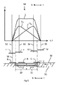
図5は、図2から図4bによる実施形態におけるスケール1が設けられた路面5の下部断面図を概略的に示す線図であり、スケール1は、軽量ユニット10、11、支持プレート2及びベースプレート3を備え、該スケール1は、路面に埋め込まれ、地面51上にある。図面には、図1に従ったタイヤ接触領域A,B及びCの位置が示されている。
FIG. 5 is a diagram schematically showing a lower sectional view of a road surface 5 provided with the
より明確にするために、スケール1上を走行する車両のタイヤ接触領域I〜IVが、さらに上方に示されており、各接触位置I〜IVは、以下に説明する特別な位置である。
・タイヤ接触領域Iは、走行方向(長さlの方向)から見て、支持プレート2の前縁2'の直前に位置している。
・タイヤ接触領域IIは、前縁2'の直ぐ後に位置しており、その結果、タイヤは、支持プレート2に完全に載っている。
・接触領域IIIは、後縁2''の直ぐ手前にあり、タイヤがまさに支持プレート2上に未だ完全に残っている時の瞬間である。
・接触領域IVは、タイヤが支持プレート2から完全に下りた状態を示している。
For the sake of clarity, the tire contact areas I to IV of the vehicle traveling on the
The tire contact area I is located immediately in front of the
The tire contact area II is located directly behind the
The contact area III is just before the trailing
The contact area IV indicates a state in which the tire has completely descended from the
タイヤに属する車輪の車軸の各位置は、これらタイヤ接触領域I〜IVに割り当てられ、前記車軸の位置は、垂直線52〜55で示すように、自然にタイヤ接触領域の中間に位置することになる。
The positions of the axles of the wheels belonging to the tire are assigned to these tire contact areas I to IV, and the position of said axles is naturally located in the middle of the tire contact areas, as indicated by
線52〜55は、グラフ56の中まで延びている。グラフ56において、水平線は、走行方向における距離sを示しており、かつ、測定すべき車両が一定速度であると仮定した時の時間tも示している。純粋に定性的な量の荷重信号Gは、縦軸にプロットされており、即ち、計量ユニット10の部分荷重信号TL1の曲線(変形センサ7の信号)、計量ユニット11の部分荷重信号TL2の曲線(変形センサ15の信号)、並びに、部分荷重信号TL1及びTL2の合計としての荷重信号Lの曲線が示されている。
Lines 52-55 extend into
スケール1の構造から、荷重が、支持要素、即ち、支持プレート2の中心に正確に位置している場合を除いて、荷重がスケール1を通過する時に部分荷重信号TL1及びTL2は、各々異なる値をとることになる。
Due to the structure of the
また、タイヤ接触領域I及び線52で示すように、タイヤが未だ支持プレート2に達していない時は、計量ユニット10の部分荷重信号TL1は、最小、即ち、ゼロになる。タイヤ接触領域II及び線53で示すように、タイヤが完全に支持プレート2に載ると直ぐに、部分荷重信号TL1は最大に達する。タイヤ接触領域IVで示すように、タイヤが完全にスケール1から離れると直ぐに、部分荷重信号は、ゼロまで連続的に下がる。
Also, as indicated by the tire contact area I and
同様に、部分荷重信号TL2については、例えば、タイヤ接触領域A及び線56で示すように、タイヤ接触領域の前端がスケール1に達すると直ぐに上がり始め、接触領域IIIで示すように、タイヤ接触領域が、支持プレート2の後縁2''の直前に位置すると直ぐに、部分荷重信号TL2の連続的な上昇は最大まで達し、タイヤ接触領域IVで示すように、タイヤが完全にスケール1から離れると直ぐに、部分荷重信号TL2はゼロまで落ちる。
Similarly, for the partial load signal TL2, for example, as shown by the tire contact area A and
このグラフは、車輪がスケール1上を走行している間に、部分荷重信号TL1が急激に上昇し、次いで、タイヤが完全にスケール1から降りるまでゆっくり下降し、逆に、ホイールがスケールを走行して、スケールを横切っている間に、部分荷重信号TL2がゆっくり上昇し、次いで、車輪がスケール1上に部分的にのみ載っている状態になると直ぐに急激に下降することを示している。
This graph shows that while the wheel is traveling on the
支持プレート2を走行するタイヤのエネルギによる荷重信号TL1、TL2の前述の乱れをある程度示しているだけであり、例えば、このような乱れのために、評価は非常に難しくなり、タイヤがスケール1の上に完全に位置している限り、ゼロからの部分荷重信号TL1及びTL2の立ち上がりは、時間的に正確には決めることができず、同様に、合計の荷重信号Lの立ち上がりフランクの水平領域への遷移も正確に決めることができない。
It only shows to some extent the aforementioned disturbances of the load signals TL1, TL2 due to the energy of the tires running on the
本発明によれば、タイヤの速度、タイヤ接触領域の重量及び長さは、以下のように計算することができる。タイヤは、タイヤ接触領域の位置IIからタイヤ接触領域の位置IVに達した時に、スケール1の長さを移動したことになる。一方において部分荷重信号TL1は位置IIにおいて最大値になり、それは数学的アルゴリズムによって水平分岐への単なる遷移(荷重信号L)よりはるかに鋭く検出することができ、他方において、部分荷重信号TL2は、位置IVにおいて鋭くゼロまで下降し、ゼロ値に達する時間は、部分信号TL1がゆっくり降下する場合よりもはるかに正確に計算することができるので、これらの位置は比較的良好に決定されることができる。
According to the present invention, the tire speed, the weight and length of the tire contact area can be calculated as follows. The tire has moved the length of the
本発明によれば、好ましくは、タイヤの速度は、部分荷重信号TL1が最大値の時と、部分荷重信号TL2のゼロ値に達した時との間の時間によって、スケール1の長さを除算することで得られる。同様に、速度は、逆に、部分荷重信号TL1が(より急激に)上昇する時と、部分荷重信号TL2が最大になる時との間の時間にわたって計算することもできる。
According to the invention, preferably the speed of the tire is the length of
本発明による方法によれば、速度は、好ましくは、第一の部分荷重信号TL1の最大値と、第二の部分荷重信号TL2の最小値との間の時間差、又は、第一部分荷重信号TL1の最小値と、第二部分荷重信号TL2の最大値との間の時間差から、関連する測定部分の長さlに関連して決められる。
According to the method according to the invention, the velocity is preferably the time difference between the maximum value of the first partial load signal TL1 and the minimum value of the second partial load signal TL2, or of the first partial load signal TL1. From the time difference between the minimum value and the maximum value of the second part load signal TL2, it is determined in relation to the
速度が決まると、荷重の計算が可能になり、例えば、次式を用いて、最初に、部分荷重信号TL1及びTL2が加算され、次いで、平均化される。
式中、限界t1及びt2は、設定する必要がある。
本発明によれば、明確に定義可能な部分荷重曲線TL1及びTL2のが適している。
Once the speed is determined, the load can be calculated, for example using the following equation, the partial load signals TL1 and TL2 are first added and then averaged.
In the formula, the limits t1 and t2 need to be set.
According to the invention, clearly definable partial load curves TL1 and TL2 are suitable.
部分荷重曲線TL1及びTL2は、好ましくは、t1及びt2に使用されるが、部分荷重信号TL1の急上昇の開始(線52)がt1として使用され、部分荷重信号TL2の急下降(線55)がt2として使用される。これは、荷重信号Lが、部分荷重曲線TL1及びTL2の最大値間で利用可能であるよりも長い時間、例えば2倍の時間にわたって平均化され得るという利点を有する。例えば、上記のように、スケール1の長さが30cm、タイヤ接触領域A〜C及びI〜IVの長さが10cmであると仮定すると、最大値間の長さは20cmになり(線53及び54)、部分荷重信号TL1の開始ゼロ値、即ち、その最小値と、部分荷重信号TL2の第二の終了ゼロ値までの急下降、即ち、その第二最小値との間の長さは40cmになる(線52及び55)。
The partial load curves TL1 and TL2 are preferably used for t1 and t2, but the start of the partial load signal TL1 jump (line 52) is used as t1 and the partial load signal TL2 jump (line 55) is used. Used as t2. This has the advantage that the load signal L can be averaged over a longer time than is available between the maximum values of the partial load curves TL1 and TL2, for example twice as long. For example, assuming that the
進行方向は、部分荷重曲線の最大値の時系列から決定することができ、これは、これは、車両専用道路のための料金所や他の施設において予め決められた方向と反対に荷重が移動することを検知するために重要である。 The direction of travel can be determined from the time series of maximum values of the partial load curve, which means that the load travels against the predetermined direction at toll booths or other facilities for vehicle lanes. It is important to detect what to do.
好ましくは、時間tにわたる荷重信号Lの平均化は、時間tに亘って信号Lを積分し、かつ、荷重の移動速度で除算することによって達成される。さらに好ましくは、、荷重信号の平均化は、第一部分荷重信号TL1の初期上昇(ライン52)で始まり、好ましくは、最後の部分荷重信号TL2がゼロ値(ライン55)に到達すると終わる。最後に、本発明によれば、好ましくは二つの部分荷重信号の合計が荷重信号を生成し、第一及び第二の部分荷重信号が、それぞれ同じ時間間隔限界で始まり、かつ、終わり、その時間間隔において、最大値を有する。 Preferably, the averaging of the load signal L over time t is achieved by integrating the signal L over time t and dividing by the speed of movement of the load. More preferably, the averaging of the load signals begins with an initial rise of the first partial load signal TL1 (line 52) and preferably ends when the last partial load signal TL2 reaches a zero value (line 55). Finally, according to the invention, preferably the sum of the two partial load signals produces a load signal, the first and second partial load signals each starting and ending at the same time interval limit, the time of which It has a maximum in the interval.
要約すると、本発明によれば、スケール上を移動する荷重の重量を計算する方法が提供され、この方法では、スケールの荷重信号は、荷重の速度を用いてある期間に亘って平均化され、合計で荷重信号を生成する複数の部分荷重信号が使用され、第一の部分荷重信号は、荷重がスケールの測定部分に完全に載ると直ぐに最大を示し、第二の部分荷重信号は、荷重がスケールの測定部分から完全に下りると直ぐに最小値を示し、荷重の移動速度は、これら部分荷重信号から決められる。 In summary, the invention provides a method of calculating the weight of a load moving on a scale, wherein the load signal of the scale is averaged over a period of time using the velocity of the load, Multiple partial load signals are used to generate a total load signal, the first partial load signal showing a maximum as soon as the load is fully seated on the measuring part of the scale, and the second partial load signal is As soon as it completely descends from the measuring part of the scale, it shows a minimum value, and the moving speed of the load is determined from these partial load signals.
接触領域の長さは、例えば、第二部分荷重曲線TL2の最大値と、それに続くゼロ値との間の時間に、決められた速度を乗算することによって決めることができ、又は、逆に、部分荷重信号TLの急勾配の立ち上がり時間から同様に決めることができる。 The length of the contact area can be determined, for example, by multiplying the time between the maximum value of the second partial load curve TL2 and the subsequent zero value by the determined speed, or vice versa. It can be similarly determined from the steep rising time of the partial load signal TL.
本発明による方法では、スケールの支持要素状の荷重の接触領域の長さは、この部分荷重信号が、この荷重の荷重値を生成する総時間に関して、荷重がスケールに丁度到達するか、又は丁度離れることによって部分荷重信号が表す最小値と、荷重がスケール上に完全にあるか、又はスケール上に未だ完全にある時に部分荷重信号が表す最大値の範囲内の時間によって決められる。接触領域の長さは、例えば、タイヤの空気圧が不十分であること(又は過度に高いものであること)を示すものでああり得、又は他の目的に使用される。 In the method according to the invention, the length of the contact area of the load, which is like a support element of the scale, is such that the load reaches exactly the scale or exactly with respect to the total time that this partial load signal produces the load value of this load. The separation is determined by the minimum value represented by the partial load signal and the time within the maximum value represented by the partial load signal when the load is either completely on the scale or is still completely on the scale. The length of the contact area can be, for example, an indication that the tire is under-inflated (or too high), or is used for other purposes.
請求項7に記載のスケールの構成は、また、本発明に従ったものであり、支持要素は支持プレートとして構成され、車線内にある複数のスケールは、相互に並べて配置された支持プレートを有し、かつ、前記車線に対して直角の角度で配置され、中央演算ユニットは、各スケールの変形センサの部分荷重信号を評価し、かつ、演算ユニットのインターフェイスにおいてスケール上を移動する車軸の速度、重量及び進行方向の少なくとも一つを決める。 The construction of the scale according to claim 7 is also in accordance with the invention, wherein the support element is configured as a support plate and the scales in the lane have support plates arranged next to one another. And arranged at a right angle to the lane, the central processing unit evaluates the partial load signals of the deformation sensors of each scale, and at the interface of the processing unit the speed of the axle moving on the scale, At least one of weight and traveling direction is determined.
Claims (18)
前記スケール(1)が複数の計量ユニット(10,11)と、前記複数の計量ユニット(10,11)に跨って重量を伝達する支持要素とを備え、前記複数の計量ユニット(10,11)から部分荷重信号を得るように構成されたスケール(1)であり、
スケール(1)の荷重信号が、荷重の速度を用いて、ある期間平均化される方法において、
合計で荷重信号を生成する複数の部分荷重信号(TL1、TL2)が使用され、
第一部分荷重信号(TL1)が、スケール(1)の測定部分に荷重が完全に載せられると直ぐに、最大値を示し、
第二部分荷重信号(TL2)が、スケール(1)の測定部分から荷重が完全に下りると直ぐに、最小値を示し、
荷重の移動速度が、これら部分荷重信号(TL1、TL2)から決められる
ことを特徴とする方法。 A method of calculating the weight of a load moving on a scale (1), comprising:
The scale (1) includes a plurality of weighing units (10, 11) and a support element that transfers weight across the plurality of weighing units (10, 11), and the plurality of weighing units (10, 11). A scale (1) configured to obtain a partial load signal from
In a method where the load signal of scale (1) is averaged over a period of time using the velocity of the load,
Multiple partial load signals (TL1, TL2) are used to generate a total load signal,
The first part load signal (TL1) shows a maximum value as soon as the load is completely placed on the measuring part of the scale (1),
The second partial load signal (TL2) shows a minimum value as soon as the load is completely off the measuring part of the scale (1),
The moving speed of the load is determined from these partial load signals (TL1, TL2).
ことを特徴とする請求項1に記載の方法。 The method according to claim 1, wherein:
ことを特徴とする請求項1に記載の方法。 Method according to claim 1, characterized in that the averaging of the load signal (L) over time is performed by integrating the load signal (L) over time and dividing by the speed of movement of the load.
ことを特徴とする請求項1に記載の方法。 Method according to claim 1, characterized in that the averaging of the load signal (L) is already started with an initial rise of the first partial load signal (TL1).
ことを特徴とする請求項4に記載の方法。 Method according to claim 4 , characterized in that the averaging of the load signal (L) does not end until the last partial load signal (TL2) reaches a value of zero.
第一部分荷重信号(TL1)の最大値と、時間的に次の第二部分荷重信号(TL2)の最小値との間の時間差に基づいて決められるか、又は、
第一部分荷重信号(TL1)の最小値と、第二部分荷重信号(TL2)の時間的に次の最大値との間の時間差に基づいて決められる
ことを特徴とする請求項1に記載の方法。 The speed of movement of the load moving on the scale is related to the length l of the relevant measuring part:
Determined on the basis of the time difference between the maximum value of the first partial load signal (TL1) and the minimum value of the second partial load signal (TL2) that is next in time, or
Method according to claim 1, characterized in that it is determined on the basis of the time difference between the minimum value of the first partial load signal (TL1) and the next maximum value of the second partial load signal (TL2) in time. ..
部分荷重信号(TL1、TL2)が、荷重に対する部分荷重信号を生成する総時間に関して、
部分荷重信号(TL1、TL2)が、
荷重がスケール(1)に丁度達するか、又は丁度降りることにより最小値を示し、かつ、
荷重がスケール(1)上に完全に位置するか、又はスケール(1)上に未だ位置している時に最大値を示す
範囲内の時間によって決められる
ことを特徴とする請求項1に記載の方法。 The length of the contact areas (AC and I-IV) of the load moving on the scale in the support element of the scale (1) is
The partial load signals (TL1, TL2) are in terms of the total time to generate the partial load signals for the loads,
Partial load signals (TL1, TL2)
The minimum value is shown when the load reaches the scale (1) or gets off the scale, and
The method according to claim 1, characterized in that the load is located completely on the scale (1) or is determined by the time within the range of maximum when still located on the scale (1). ..
第一及び第二の部分荷重信号(TL1、TL2)が、同じ時間間隔制限内で開始及び終了し、かつ、その間隔内に最大値を有する
ことを特徴とする請求項1に記載の方法。 The two partial load signals (TL1, TL2) together generate a load signal (L), and
Method according to claim 1, characterized in that the first and second partial load signals (TL1, TL2) start and end within the same time interval limit and have a maximum in that interval.
スケール(1)上を移動する荷重の重量を形成するスケール(1)であって、
支持要素及び計量構造を有するスケール(1)において、
計量構造(18)が、複数の計量ユニット(10,11)を有し、
各計量ユニット(10,11)が、部分荷重信号を生成する変形センサ(7,15)を有する曲げ変形要素を備え、
計量ユニット(10,11)が、荷重の移動方向に順番に配置され、
支持要素が、計量ユニットに跨り、重量を伝達し、その一端が第一計量ユニット(10)の変形要素に作用し、その他端が第二計量ユニット(11)の変形要素に作用する
ようにしたことを特徴とするスケール。 A scale (1) using the method according to any one of claims 1 to 8 ,
A scale (1) forming a weight of load moving on the scale (1),
In a scale (1) with a support element and a weighing structure,
The weighing structure (18) has a plurality of weighing units (10, 11),
Each weighing unit (10, 11) comprises a bending deformation element with a deformation sensor (7, 15) generating a partial load signal,
The weighing units (10, 11) are sequentially arranged in the moving direction of the load,
The supporting element straddles the weighing unit and transfers weight, one end of which acts on the deforming element of the first weighing unit (10) and the other end of which acts on the deforming element of the second weighing unit (11). A scale characterized by that.
計量ユニット(10,11)の曲げ変形要素が、本質的に、支持プレート(2)と平行に延び、かつ、荷重の移動方向において対向する両端部が地面(3)に置かれ、
曲げ変形要素が重量の影響下で曲がるように、ベアリング間、好ましくは、複数のベアリングの一つに隣接するベアリング間に重量が作用する
ことを特徴とする請求項9に記載のスケール。 The support element is configured as a support plate (2),
The bending deformation element of the weighing unit (10, 11) extends essentially parallel to the support plate (2), and its opposite ends in the direction of movement of the load are placed on the ground (3),
10. Scale according to claim 9 , characterized in that the weight acts between the bearings, preferably between the bearings adjacent to one of the plurality of bearings, such that the bending deformation element bends under the influence of the weight.
重量が、横方向ビーム(5,13)の長さに亘って直線的に作用し、
変形センサ(7,15)が脚部(6,14)の範囲にある変形要素の曲げを検知する
ことを特徴とする請求項9に記載のスケール。 The bending deformation element has a T-shaped outer shape,
The weight acts linearly over the length of the transverse beam (5, 13),
Scale according to claim 9 , characterized in that the deformation sensor (7, 15) detects bending of the deformation element in the region of the leg (6, 14).
重量が、振り子式ベアリング(23,36)を介して変形要素上に作用する
ようにしたことを特徴とする請求項9に記載のスケール。 The deformable element is the ground on which the weight acts, with a fixed bearing (24, 27) at one of its ends and a movable bearing (25, 28) at the end opposite its one end. Supported above,
10. Scale according to claim 9 , characterized in that the weight acts on the deformation element via a pendulum bearing (23, 36).
ことを特徴とする請求項9に記載のスケール。 Scale according to claim 9 , characterized in that the first weighing unit (10) and the second weighing unit (11) are arranged such that their deformation elements are adjacent to each other.
ことを特徴とする請求項11及び13に記載のスケール。 Scale according to claims 11 and 13 , characterized in that the weighing units (10, 11) are constructed in the same way and their legs are arranged to face each other.
ことを特徴とする請求項9に記載のスケール。 Scale according to claim 9 , characterized in that the deformation sensor of the weighing unit (10, 11) is configured as a vibrating wire sensor.
ことを特徴とする請求項9に記載のスケール。 The scale according to claim 9 , wherein the length of the load in the moving direction is shorter than 50 cm, preferably 30 cm.
ことを特徴とする請求項9に記載のスケール。 Scale according to claim 9 , characterized in that its width is less than 100 cm, preferably 60 cm.
その支持要素が、支持プレート(2)として構成され、
車線内に配置され、かつ、相互に並べて配置された支持プレート(2)を有する複数のスケール(1)が前記車線に対して直角に配置され、
中央演算ユニットが、個々のスケールの変形センサの部分荷重信号を評価し、かつ、コンピュータユニットのインターフェイスで、スケール上を移動する車軸の速度、重量又は進行方向の値の少なくとも一つを決定する
ことを特徴とする構造。 The structure of the scale (1) according to claim 9 , wherein
The support element is configured as a support plate (2),
A plurality of scales (1) arranged in a lane and having support plates (2) arranged next to each other are arranged at right angles to said lane,
The central processing unit evaluates the partial load signals of the deformation sensors of the individual scales and at the interface of the computer unit determines at least one of the speed, weight or heading values of the axle moving on the scale. Structure characterized by.
Applications Claiming Priority (3)
| Application Number | Priority Date | Filing Date | Title |
|---|---|---|---|
| CH01566/16 | 2016-11-29 | ||
| CH01566/16A CH713161A2 (en) | 2016-11-29 | 2016-11-29 | Method for detecting the weight of a load moving across a balance, and a balance. |
| PCT/IB2017/057396 WO2018100475A2 (en) | 2016-11-29 | 2017-11-24 | Method and device for detecting the weight of a load moving on scales |
Related Child Applications (1)
| Application Number | Title | Priority Date | Filing Date |
|---|---|---|---|
| JP2020119961A Division JP7097094B2 (en) | 2016-11-29 | 2020-07-13 | Method and device for detecting the weight of a load moving on a scale |
Publications (2)
| Publication Number | Publication Date |
|---|---|
| JP2020513566A JP2020513566A (en) | 2020-05-14 |
| JP6746006B2 true JP6746006B2 (en) | 2020-08-26 |
Family
ID=60655025
Family Applications (2)
| Application Number | Title | Priority Date | Filing Date |
|---|---|---|---|
| JP2019543017A Active JP6746006B2 (en) | 2016-11-29 | 2017-11-24 | Method and apparatus for detecting weight of load moving on scale |
| JP2020119961A Active JP7097094B2 (en) | 2016-11-29 | 2020-07-13 | Method and device for detecting the weight of a load moving on a scale |
Family Applications After (1)
| Application Number | Title | Priority Date | Filing Date |
|---|---|---|---|
| JP2020119961A Active JP7097094B2 (en) | 2016-11-29 | 2020-07-13 | Method and device for detecting the weight of a load moving on a scale |
Country Status (7)
| Country | Link |
|---|---|
| US (1) | US11473962B2 (en) |
| EP (1) | EP3548852A2 (en) |
| JP (2) | JP6746006B2 (en) |
| CN (1) | CN110268237A (en) |
| CA (1) | CA3045252C (en) |
| CH (1) | CH713161A2 (en) |
| WO (1) | WO2018100475A2 (en) |
Families Citing this family (1)
| Publication number | Priority date | Publication date | Assignee | Title |
|---|---|---|---|---|
| JP6939885B2 (en) * | 2017-08-10 | 2021-09-22 | 株式会社村田製作所 | Strain sensor and its manufacturing method |
Family Cites Families (24)
| Publication number | Priority date | Publication date | Assignee | Title |
|---|---|---|---|---|
| GB1123211A (en) * | 1965-03-03 | 1968-08-14 | Avery Ltd W & T | An improved method and apparatus for dynamic weighing |
| JPS5323099B2 (en) * | 1973-03-12 | 1978-07-12 | ||
| US3825734A (en) * | 1973-03-14 | 1974-07-23 | Reliance Electric Co | Monitor for moving vehicles |
| JPS604413B2 (en) * | 1975-08-26 | 1985-02-04 | 阪神高速道路公団 | Vehicle load measuring device |
| JPS5388770A (en) * | 1977-01-14 | 1978-08-04 | Kyowa Electronic Instruments | Method for metering weight of axle and speed of vehicle |
| EP0025807B1 (en) | 1979-09-19 | 1984-02-01 | Wirth Gallo Patent AG | Device for measuring masses and forces |
| JPS6335923A (en) | 1986-07-29 | 1988-02-16 | Shimizu Constr Co Ltd | Basement and its construction |
| JPS6335923U (en) * | 1986-08-26 | 1988-03-08 | ||
| SE468491B (en) * | 1991-05-23 | 1993-01-25 | Lundman Ulf Pad Lastceller Ab | PROCEDURES FOR DETERMINING A DYNAMIC WEIGHT |
| US5338901A (en) | 1992-06-22 | 1994-08-16 | Kaskaskia Valley Scale Company | Conveyor belt weigher incorporating two end located parallel-beam load cells |
| JPH06186241A (en) | 1992-12-18 | 1994-07-08 | Bridgestone Corp | Method for detecting wheel speed in vehicle weight detector |
| EP0691530B1 (en) * | 1994-07-06 | 2000-02-09 | Omron Corporation | Method and apparatus for measuring axle load of a running vehicle |
| SE510761C2 (en) * | 1996-12-18 | 1999-06-21 | Vaagagenturen Waanelid Ab | Weighing device and method of weighing vehicles in motion |
| US5959259A (en) * | 1997-03-11 | 1999-09-28 | Lockheed Martin Energy Research Corporation | System and method for accurately weighing and characterizing moving vehicles |
| US6459050B1 (en) * | 1999-09-20 | 2002-10-01 | Ut-Battelle, Inc. | Method and appartus for converting static in-ground vehicle scales into weigh-in-motion systems |
| JP4114591B2 (en) | 2003-10-27 | 2008-07-09 | オムロン株式会社 | Axle load measuring device and axle load measuring method |
| JP5191856B2 (en) | 2008-10-07 | 2013-05-08 | 大和製衡株式会社 | Wheel / axle weight measurement system |
| JP5823256B2 (en) | 2011-11-01 | 2015-11-25 | 大和製衡株式会社 | Vehicle weighing device |
| CH705762A1 (en) * | 2011-11-04 | 2013-05-15 | Kistler Holding Ag | Method for weighing a vehicle, as well as measuring device and measuring chain for this purpose. |
| EP2650659A1 (en) * | 2012-04-13 | 2013-10-16 | Dynawimscale Sarl. | Weight in motion measuring device for vehicles |
| CN105021266B (en) * | 2015-07-20 | 2017-08-29 | 北京万集科技股份有限公司 | Dynamic weighing system |
| CN105352575A (en) * | 2015-11-06 | 2016-02-24 | 张家界恒亮新材料科技有限公司 | Rail transport ore bucket dynamic weighing device |
| CN205593630U (en) | 2016-03-17 | 2016-09-21 | 宁波柯力传感科技股份有限公司 | Bent plate formula vehicle overload real -time detection siren operated sensor |
| SE539735C2 (en) * | 2016-03-22 | 2017-11-14 | Motus Weighing Ab | Weighing scale and methods thereof |
-
2016
- 2016-11-29 CH CH01566/16A patent/CH713161A2/en unknown
-
2017
- 2017-11-24 CA CA3045252A patent/CA3045252C/en active Active
- 2017-11-24 CN CN201780073855.9A patent/CN110268237A/en active Pending
- 2017-11-24 US US16/464,203 patent/US11473962B2/en active Active
- 2017-11-24 EP EP17812077.0A patent/EP3548852A2/en active Pending
- 2017-11-24 JP JP2019543017A patent/JP6746006B2/en active Active
- 2017-11-24 WO PCT/IB2017/057396 patent/WO2018100475A2/en unknown
-
2020
- 2020-07-13 JP JP2020119961A patent/JP7097094B2/en active Active
Also Published As
| Publication number | Publication date |
|---|---|
| EP3548852A2 (en) | 2019-10-09 |
| CA3045252A1 (en) | 2018-06-07 |
| JP2020513566A (en) | 2020-05-14 |
| WO2018100475A2 (en) | 2018-06-07 |
| JP7097094B2 (en) | 2022-07-07 |
| CH713161A2 (en) | 2018-05-31 |
| US11473962B2 (en) | 2022-10-18 |
| US20190391003A1 (en) | 2019-12-26 |
| WO2018100475A3 (en) | 2018-08-09 |
| CA3045252C (en) | 2023-03-21 |
| CN110268237A (en) | 2019-09-20 |
| JP2020173272A (en) | 2020-10-22 |
Similar Documents
| Publication | Publication Date | Title |
|---|---|---|
| KR101812358B1 (en) | Method for calibrating wim-sensors | |
| US7942048B2 (en) | System for detecting the pressure in a vehicle tire and/or the speed of the vehicle | |
| US9804017B2 (en) | Method for weighing a vehicle, and measuring system and measuring arrangement therefor | |
| US20100292953A1 (en) | Method for ascertaining the pressure and the profile depth in a vehicle tire | |
| US11761812B2 (en) | Measurement method, measurement device, measurement system, and measurement program | |
| US11713993B2 (en) | Bridge displacement measurement method | |
| GB2494618A (en) | A sensor array for checking the pressure of a vehicle tyre | |
| CN109916491A (en) | A kind of method and system identifying move vehicle wheelbase, axis weight and gross weight | |
| JP3574850B2 (en) | Axle load measurement method for vehicles running on bridges | |
| EP3350553B1 (en) | Weight measuring device and the measuring method | |
| JP7097094B2 (en) | Method and device for detecting the weight of a load moving on a scale | |
| CN101619999A (en) | Composite material axle weight scale load recognition method based on strain measurement | |
| US11408761B2 (en) | Measurement method, measurement device, measurement system, and measurement program | |
| US20200369303A1 (en) | System and method for determining an angular speed of an axle of a railway vehicle | |
| JP2010223755A (en) | Device and method for measuring axle load | |
| Nieoczym et al. | Geometric optimization of a beam detector for a WIM system | |
| JP6083793B2 (en) | Vehicle natural frequency detection device and gravity center position measurement device | |
| RU2239798C2 (en) | Method of weighing vehicle | |
| RU166255U1 (en) | STATIONARY CAR SCALES | |
| CN108020370B (en) | Combined type weighing platform paving structure | |
| SU1059444A1 (en) | Cargo handling device for moving car balance | |
| CN116952345A (en) | Bridge dynamic weighing method based on strain area | |
| GB2480306A (en) | Weighing vehicles in motion |
Legal Events
| Date | Code | Title | Description |
|---|---|---|---|
| A521 | Request for written amendment filed |
Free format text: JAPANESE INTERMEDIATE CODE: A523 Effective date: 20190815 |
|
| A621 | Written request for application examination |
Free format text: JAPANESE INTERMEDIATE CODE: A621 Effective date: 20190807 |
|
| A871 | Explanation of circumstances concerning accelerated examination |
Free format text: JAPANESE INTERMEDIATE CODE: A871 Effective date: 20190807 |
|
| A975 | Report on accelerated examination |
Free format text: JAPANESE INTERMEDIATE CODE: A971005 Effective date: 20191129 |
|
| A131 | Notification of reasons for refusal |
Free format text: JAPANESE INTERMEDIATE CODE: A131 Effective date: 20200108 |
|
| A601 | Written request for extension of time |
Free format text: JAPANESE INTERMEDIATE CODE: A601 Effective date: 20200408 |
|
| A521 | Request for written amendment filed |
Free format text: JAPANESE INTERMEDIATE CODE: A523 Effective date: 20200526 |
|
| A131 | Notification of reasons for refusal |
Free format text: JAPANESE INTERMEDIATE CODE: A131 Effective date: 20200617 |
|
| A521 | Request for written amendment filed |
Free format text: JAPANESE INTERMEDIATE CODE: A523 Effective date: 20200713 |
|
| TRDD | Decision of grant or rejection written | ||
| A01 | Written decision to grant a patent or to grant a registration (utility model) |
Free format text: JAPANESE INTERMEDIATE CODE: A01 Effective date: 20200729 |
|
| A61 | First payment of annual fees (during grant procedure) |
Free format text: JAPANESE INTERMEDIATE CODE: A61 Effective date: 20200804 |
|
| R150 | Certificate of patent or registration of utility model |
Ref document number: 6746006 Country of ref document: JP Free format text: JAPANESE INTERMEDIATE CODE: R150 |
|
| R250 | Receipt of annual fees |
Free format text: JAPANESE INTERMEDIATE CODE: R250 |