JP6741029B2 - Information display device - Google Patents
Information display device Download PDFInfo
- Publication number
- JP6741029B2 JP6741029B2 JP2017566899A JP2017566899A JP6741029B2 JP 6741029 B2 JP6741029 B2 JP 6741029B2 JP 2017566899 A JP2017566899 A JP 2017566899A JP 2017566899 A JP2017566899 A JP 2017566899A JP 6741029 B2 JP6741029 B2 JP 6741029B2
- Authority
- JP
- Japan
- Prior art keywords
- virtual image
- information
- display device
- change
- information display
- Prior art date
- Legal status (The legal status is an assumption and is not a legal conclusion. Google has not performed a legal analysis and makes no representation as to the accuracy of the status listed.)
- Active
Links
- 230000008859 change Effects 0.000 claims description 82
- 239000003550 marker Substances 0.000 description 42
- 230000003287 optical effect Effects 0.000 description 22
- 238000000034 method Methods 0.000 description 16
- 238000010586 diagram Methods 0.000 description 8
- 230000006870 function Effects 0.000 description 7
- KNMAVSAGTYIFJF-UHFFFAOYSA-N 1-[2-[(2-hydroxy-3-phenoxypropyl)amino]ethylamino]-3-phenoxypropan-2-ol;dihydrochloride Chemical compound Cl.Cl.C=1C=CC=CC=1OCC(O)CNCCNCC(O)COC1=CC=CC=C1 KNMAVSAGTYIFJF-UHFFFAOYSA-N 0.000 description 5
- 230000015572 biosynthetic process Effects 0.000 description 5
- 241000282414 Homo sapiens Species 0.000 description 3
- 238000001514 detection method Methods 0.000 description 2
- 238000005516 engineering process Methods 0.000 description 2
- 230000008447 perception Effects 0.000 description 2
- 230000009467 reduction Effects 0.000 description 2
- 230000009466 transformation Effects 0.000 description 2
- 230000009471 action Effects 0.000 description 1
- 238000006243 chemical reaction Methods 0.000 description 1
- 150000001875 compounds Chemical class 0.000 description 1
- 238000007796 conventional method Methods 0.000 description 1
- 230000008878 coupling Effects 0.000 description 1
- 238000010168 coupling process Methods 0.000 description 1
- 238000005859 coupling reaction Methods 0.000 description 1
- 239000000428 dust Substances 0.000 description 1
- 230000004907 flux Effects 0.000 description 1
- 230000005484 gravity Effects 0.000 description 1
- 238000003384 imaging method Methods 0.000 description 1
- 230000001771 impaired effect Effects 0.000 description 1
- 230000001678 irradiating effect Effects 0.000 description 1
- 239000004973 liquid crystal related substance Substances 0.000 description 1
- 230000004048 modification Effects 0.000 description 1
- 238000012986 modification Methods 0.000 description 1
- 238000010422 painting Methods 0.000 description 1
- 230000008569 process Effects 0.000 description 1
- 210000001525 retina Anatomy 0.000 description 1
- 239000004065 semiconductor Substances 0.000 description 1
- 238000006467 substitution reaction Methods 0.000 description 1
- 230000000007 visual effect Effects 0.000 description 1
Images


Classifications
-
- G—PHYSICS
- G06—COMPUTING; CALCULATING OR COUNTING
- G06T—IMAGE DATA PROCESSING OR GENERATION, IN GENERAL
- G06T19/00—Manipulating 3D models or images for computer graphics
- G06T19/006—Mixed reality
-
- G—PHYSICS
- G06—COMPUTING; CALCULATING OR COUNTING
- G06T—IMAGE DATA PROCESSING OR GENERATION, IN GENERAL
- G06T15/00—3D [Three Dimensional] image rendering
- G06T15/50—Lighting effects
-
- B—PERFORMING OPERATIONS; TRANSPORTING
- B60—VEHICLES IN GENERAL
- B60K—ARRANGEMENT OR MOUNTING OF PROPULSION UNITS OR OF TRANSMISSIONS IN VEHICLES; ARRANGEMENT OR MOUNTING OF PLURAL DIVERSE PRIME-MOVERS IN VEHICLES; AUXILIARY DRIVES FOR VEHICLES; INSTRUMENTATION OR DASHBOARDS FOR VEHICLES; ARRANGEMENTS IN CONNECTION WITH COOLING, AIR INTAKE, GAS EXHAUST OR FUEL SUPPLY OF PROPULSION UNITS IN VEHICLES
- B60K35/00—Instruments specially adapted for vehicles; Arrangement of instruments in or on vehicles
- B60K35/20—Output arrangements, i.e. from vehicle to user, associated with vehicle functions or specially adapted therefor
- B60K35/21—Output arrangements, i.e. from vehicle to user, associated with vehicle functions or specially adapted therefor using visual output, e.g. blinking lights or matrix displays
- B60K35/23—Head-up displays [HUD]
- B60K35/231—Head-up displays [HUD] characterised by their arrangement or structure for integration into vehicles
-
- B—PERFORMING OPERATIONS; TRANSPORTING
- B60—VEHICLES IN GENERAL
- B60K—ARRANGEMENT OR MOUNTING OF PROPULSION UNITS OR OF TRANSMISSIONS IN VEHICLES; ARRANGEMENT OR MOUNTING OF PLURAL DIVERSE PRIME-MOVERS IN VEHICLES; AUXILIARY DRIVES FOR VEHICLES; INSTRUMENTATION OR DASHBOARDS FOR VEHICLES; ARRANGEMENTS IN CONNECTION WITH COOLING, AIR INTAKE, GAS EXHAUST OR FUEL SUPPLY OF PROPULSION UNITS IN VEHICLES
- B60K35/00—Instruments specially adapted for vehicles; Arrangement of instruments in or on vehicles
- B60K35/20—Output arrangements, i.e. from vehicle to user, associated with vehicle functions or specially adapted therefor
- B60K35/21—Output arrangements, i.e. from vehicle to user, associated with vehicle functions or specially adapted therefor using visual output, e.g. blinking lights or matrix displays
- B60K35/23—Head-up displays [HUD]
- B60K35/234—Head-up displays [HUD] controlling the brightness, colour or contrast of virtual images depending on the driving conditions or on the condition of the vehicle or the driver
-
- B—PERFORMING OPERATIONS; TRANSPORTING
- B60—VEHICLES IN GENERAL
- B60K—ARRANGEMENT OR MOUNTING OF PROPULSION UNITS OR OF TRANSMISSIONS IN VEHICLES; ARRANGEMENT OR MOUNTING OF PLURAL DIVERSE PRIME-MOVERS IN VEHICLES; AUXILIARY DRIVES FOR VEHICLES; INSTRUMENTATION OR DASHBOARDS FOR VEHICLES; ARRANGEMENTS IN CONNECTION WITH COOLING, AIR INTAKE, GAS EXHAUST OR FUEL SUPPLY OF PROPULSION UNITS IN VEHICLES
- B60K35/00—Instruments specially adapted for vehicles; Arrangement of instruments in or on vehicles
- B60K35/20—Output arrangements, i.e. from vehicle to user, associated with vehicle functions or specially adapted therefor
- B60K35/28—Output arrangements, i.e. from vehicle to user, associated with vehicle functions or specially adapted therefor characterised by the type of the output information, e.g. video entertainment or vehicle dynamics information; characterised by the purpose of the output information, e.g. for attracting the attention of the driver
- B60K35/285—Output arrangements, i.e. from vehicle to user, associated with vehicle functions or specially adapted therefor characterised by the type of the output information, e.g. video entertainment or vehicle dynamics information; characterised by the purpose of the output information, e.g. for attracting the attention of the driver for improving awareness by directing driver's gaze direction or eye points
-
- B—PERFORMING OPERATIONS; TRANSPORTING
- B60—VEHICLES IN GENERAL
- B60K—ARRANGEMENT OR MOUNTING OF PROPULSION UNITS OR OF TRANSMISSIONS IN VEHICLES; ARRANGEMENT OR MOUNTING OF PLURAL DIVERSE PRIME-MOVERS IN VEHICLES; AUXILIARY DRIVES FOR VEHICLES; INSTRUMENTATION OR DASHBOARDS FOR VEHICLES; ARRANGEMENTS IN CONNECTION WITH COOLING, AIR INTAKE, GAS EXHAUST OR FUEL SUPPLY OF PROPULSION UNITS IN VEHICLES
- B60K35/00—Instruments specially adapted for vehicles; Arrangement of instruments in or on vehicles
- B60K35/80—Arrangements for controlling instruments
- B60K35/81—Arrangements for controlling instruments for controlling displays
-
- G—PHYSICS
- G02—OPTICS
- G02B—OPTICAL ELEMENTS, SYSTEMS OR APPARATUS
- G02B27/00—Optical systems or apparatus not provided for by any of the groups G02B1/00 - G02B26/00, G02B30/00
- G02B27/01—Head-up displays
-
- G—PHYSICS
- G06—COMPUTING; CALCULATING OR COUNTING
- G06F—ELECTRIC DIGITAL DATA PROCESSING
- G06F3/00—Input arrangements for transferring data to be processed into a form capable of being handled by the computer; Output arrangements for transferring data from processing unit to output unit, e.g. interface arrangements
- G06F3/14—Digital output to display device ; Cooperation and interconnection of the display device with other functional units
- G06F3/147—Digital output to display device ; Cooperation and interconnection of the display device with other functional units using display panels
-
- G—PHYSICS
- G06—COMPUTING; CALCULATING OR COUNTING
- G06T—IMAGE DATA PROCESSING OR GENERATION, IN GENERAL
- G06T11/00—2D [Two Dimensional] image generation
- G06T11/60—Editing figures and text; Combining figures or text
-
- G—PHYSICS
- G08—SIGNALLING
- G08G—TRAFFIC CONTROL SYSTEMS
- G08G1/00—Traffic control systems for road vehicles
- G08G1/09—Arrangements for giving variable traffic instructions
- G08G1/0962—Arrangements for giving variable traffic instructions having an indicator mounted inside the vehicle, e.g. giving voice messages
-
- G—PHYSICS
- G08—SIGNALLING
- G08G—TRAFFIC CONTROL SYSTEMS
- G08G1/00—Traffic control systems for road vehicles
- G08G1/16—Anti-collision systems
- G08G1/166—Anti-collision systems for active traffic, e.g. moving vehicles, pedestrians, bikes
-
- G—PHYSICS
- G09—EDUCATION; CRYPTOGRAPHY; DISPLAY; ADVERTISING; SEALS
- G09G—ARRANGEMENTS OR CIRCUITS FOR CONTROL OF INDICATING DEVICES USING STATIC MEANS TO PRESENT VARIABLE INFORMATION
- G09G5/00—Control arrangements or circuits for visual indicators common to cathode-ray tube indicators and other visual indicators
-
- B—PERFORMING OPERATIONS; TRANSPORTING
- B60—VEHICLES IN GENERAL
- B60K—ARRANGEMENT OR MOUNTING OF PROPULSION UNITS OR OF TRANSMISSIONS IN VEHICLES; ARRANGEMENT OR MOUNTING OF PLURAL DIVERSE PRIME-MOVERS IN VEHICLES; AUXILIARY DRIVES FOR VEHICLES; INSTRUMENTATION OR DASHBOARDS FOR VEHICLES; ARRANGEMENTS IN CONNECTION WITH COOLING, AIR INTAKE, GAS EXHAUST OR FUEL SUPPLY OF PROPULSION UNITS IN VEHICLES
- B60K2360/00—Indexing scheme associated with groups B60K35/00 or B60K37/00 relating to details of instruments or dashboards
- B60K2360/16—Type of output information
- B60K2360/177—Augmented reality
-
- B—PERFORMING OPERATIONS; TRANSPORTING
- B60—VEHICLES IN GENERAL
- B60K—ARRANGEMENT OR MOUNTING OF PROPULSION UNITS OR OF TRANSMISSIONS IN VEHICLES; ARRANGEMENT OR MOUNTING OF PLURAL DIVERSE PRIME-MOVERS IN VEHICLES; AUXILIARY DRIVES FOR VEHICLES; INSTRUMENTATION OR DASHBOARDS FOR VEHICLES; ARRANGEMENTS IN CONNECTION WITH COOLING, AIR INTAKE, GAS EXHAUST OR FUEL SUPPLY OF PROPULSION UNITS IN VEHICLES
- B60K2360/00—Indexing scheme associated with groups B60K35/00 or B60K37/00 relating to details of instruments or dashboards
- B60K2360/16—Type of output information
- B60K2360/179—Distances to obstacles or vehicles
-
- B—PERFORMING OPERATIONS; TRANSPORTING
- B60—VEHICLES IN GENERAL
- B60K—ARRANGEMENT OR MOUNTING OF PROPULSION UNITS OR OF TRANSMISSIONS IN VEHICLES; ARRANGEMENT OR MOUNTING OF PLURAL DIVERSE PRIME-MOVERS IN VEHICLES; AUXILIARY DRIVES FOR VEHICLES; INSTRUMENTATION OR DASHBOARDS FOR VEHICLES; ARRANGEMENTS IN CONNECTION WITH COOLING, AIR INTAKE, GAS EXHAUST OR FUEL SUPPLY OF PROPULSION UNITS IN VEHICLES
- B60K2360/00—Indexing scheme associated with groups B60K35/00 or B60K37/00 relating to details of instruments or dashboards
- B60K2360/20—Optical features of instruments
- B60K2360/31—Virtual images
-
- B—PERFORMING OPERATIONS; TRANSPORTING
- B60—VEHICLES IN GENERAL
- B60K—ARRANGEMENT OR MOUNTING OF PROPULSION UNITS OR OF TRANSMISSIONS IN VEHICLES; ARRANGEMENT OR MOUNTING OF PLURAL DIVERSE PRIME-MOVERS IN VEHICLES; AUXILIARY DRIVES FOR VEHICLES; INSTRUMENTATION OR DASHBOARDS FOR VEHICLES; ARRANGEMENTS IN CONNECTION WITH COOLING, AIR INTAKE, GAS EXHAUST OR FUEL SUPPLY OF PROPULSION UNITS IN VEHICLES
- B60K2360/00—Indexing scheme associated with groups B60K35/00 or B60K37/00 relating to details of instruments or dashboards
- B60K2360/20—Optical features of instruments
- B60K2360/33—Illumination features
- B60K2360/334—Projection means
-
- B—PERFORMING OPERATIONS; TRANSPORTING
- B60—VEHICLES IN GENERAL
- B60K—ARRANGEMENT OR MOUNTING OF PROPULSION UNITS OR OF TRANSMISSIONS IN VEHICLES; ARRANGEMENT OR MOUNTING OF PLURAL DIVERSE PRIME-MOVERS IN VEHICLES; AUXILIARY DRIVES FOR VEHICLES; INSTRUMENTATION OR DASHBOARDS FOR VEHICLES; ARRANGEMENTS IN CONNECTION WITH COOLING, AIR INTAKE, GAS EXHAUST OR FUEL SUPPLY OF PROPULSION UNITS IN VEHICLES
- B60K2360/00—Indexing scheme associated with groups B60K35/00 or B60K37/00 relating to details of instruments or dashboards
- B60K2360/20—Optical features of instruments
- B60K2360/33—Illumination features
- B60K2360/347—Optical elements for superposition of display information
-
- B—PERFORMING OPERATIONS; TRANSPORTING
- B60—VEHICLES IN GENERAL
- B60K—ARRANGEMENT OR MOUNTING OF PROPULSION UNITS OR OF TRANSMISSIONS IN VEHICLES; ARRANGEMENT OR MOUNTING OF PLURAL DIVERSE PRIME-MOVERS IN VEHICLES; AUXILIARY DRIVES FOR VEHICLES; INSTRUMENTATION OR DASHBOARDS FOR VEHICLES; ARRANGEMENTS IN CONNECTION WITH COOLING, AIR INTAKE, GAS EXHAUST OR FUEL SUPPLY OF PROPULSION UNITS IN VEHICLES
- B60K35/00—Instruments specially adapted for vehicles; Arrangement of instruments in or on vehicles
- B60K35/20—Output arrangements, i.e. from vehicle to user, associated with vehicle functions or specially adapted therefor
- B60K35/21—Output arrangements, i.e. from vehicle to user, associated with vehicle functions or specially adapted therefor using visual output, e.g. blinking lights or matrix displays
- B60K35/23—Head-up displays [HUD]
- B60K35/232—Head-up displays [HUD] controlling the projection distance of virtual images depending on the condition of the vehicle or the driver
-
- B—PERFORMING OPERATIONS; TRANSPORTING
- B60—VEHICLES IN GENERAL
- B60K—ARRANGEMENT OR MOUNTING OF PROPULSION UNITS OR OF TRANSMISSIONS IN VEHICLES; ARRANGEMENT OR MOUNTING OF PLURAL DIVERSE PRIME-MOVERS IN VEHICLES; AUXILIARY DRIVES FOR VEHICLES; INSTRUMENTATION OR DASHBOARDS FOR VEHICLES; ARRANGEMENTS IN CONNECTION WITH COOLING, AIR INTAKE, GAS EXHAUST OR FUEL SUPPLY OF PROPULSION UNITS IN VEHICLES
- B60K35/00—Instruments specially adapted for vehicles; Arrangement of instruments in or on vehicles
- B60K35/20—Output arrangements, i.e. from vehicle to user, associated with vehicle functions or specially adapted therefor
- B60K35/21—Output arrangements, i.e. from vehicle to user, associated with vehicle functions or specially adapted therefor using visual output, e.g. blinking lights or matrix displays
- B60K35/23—Head-up displays [HUD]
- B60K35/235—Head-up displays [HUD] with means for detecting the driver's gaze direction or eye points
-
- B—PERFORMING OPERATIONS; TRANSPORTING
- B60—VEHICLES IN GENERAL
- B60K—ARRANGEMENT OR MOUNTING OF PROPULSION UNITS OR OF TRANSMISSIONS IN VEHICLES; ARRANGEMENT OR MOUNTING OF PLURAL DIVERSE PRIME-MOVERS IN VEHICLES; AUXILIARY DRIVES FOR VEHICLES; INSTRUMENTATION OR DASHBOARDS FOR VEHICLES; ARRANGEMENTS IN CONNECTION WITH COOLING, AIR INTAKE, GAS EXHAUST OR FUEL SUPPLY OF PROPULSION UNITS IN VEHICLES
- B60K35/00—Instruments specially adapted for vehicles; Arrangement of instruments in or on vehicles
- B60K35/60—Instruments characterised by their location or relative disposition in or on vehicles
-
- G—PHYSICS
- G02—OPTICS
- G02B—OPTICAL ELEMENTS, SYSTEMS OR APPARATUS
- G02B27/00—Optical systems or apparatus not provided for by any of the groups G02B1/00 - G02B26/00, G02B30/00
- G02B27/01—Head-up displays
- G02B27/0101—Head-up displays characterised by optical features
- G02B2027/0129—Head-up displays characterised by optical features comprising devices for correcting parallax
-
- G—PHYSICS
- G02—OPTICS
- G02B—OPTICAL ELEMENTS, SYSTEMS OR APPARATUS
- G02B27/00—Optical systems or apparatus not provided for by any of the groups G02B1/00 - G02B26/00, G02B30/00
- G02B27/01—Head-up displays
- G02B27/0101—Head-up displays characterised by optical features
- G02B2027/0138—Head-up displays characterised by optical features comprising image capture systems, e.g. camera
-
- G—PHYSICS
- G02—OPTICS
- G02B—OPTICAL ELEMENTS, SYSTEMS OR APPARATUS
- G02B27/00—Optical systems or apparatus not provided for by any of the groups G02B1/00 - G02B26/00, G02B30/00
- G02B27/01—Head-up displays
- G02B27/0101—Head-up displays characterised by optical features
- G02B2027/014—Head-up displays characterised by optical features comprising information/image processing systems
-
- G—PHYSICS
- G09—EDUCATION; CRYPTOGRAPHY; DISPLAY; ADVERTISING; SEALS
- G09G—ARRANGEMENTS OR CIRCUITS FOR CONTROL OF INDICATING DEVICES USING STATIC MEANS TO PRESENT VARIABLE INFORMATION
- G09G2320/00—Control of display operating conditions
- G09G2320/02—Improving the quality of display appearance
- G09G2320/0261—Improving the quality of display appearance in the context of movement of objects on the screen or movement of the observer relative to the screen
-
- G—PHYSICS
- G09—EDUCATION; CRYPTOGRAPHY; DISPLAY; ADVERTISING; SEALS
- G09G—ARRANGEMENTS OR CIRCUITS FOR CONTROL OF INDICATING DEVICES USING STATIC MEANS TO PRESENT VARIABLE INFORMATION
- G09G2320/00—Control of display operating conditions
- G09G2320/06—Adjustment of display parameters
- G09G2320/0693—Calibration of display systems
-
- G—PHYSICS
- G09—EDUCATION; CRYPTOGRAPHY; DISPLAY; ADVERTISING; SEALS
- G09G—ARRANGEMENTS OR CIRCUITS FOR CONTROL OF INDICATING DEVICES USING STATIC MEANS TO PRESENT VARIABLE INFORMATION
- G09G2340/00—Aspects of display data processing
- G09G2340/12—Overlay of images, i.e. displayed pixel being the result of switching between the corresponding input pixels
-
- G—PHYSICS
- G09—EDUCATION; CRYPTOGRAPHY; DISPLAY; ADVERTISING; SEALS
- G09G—ARRANGEMENTS OR CIRCUITS FOR CONTROL OF INDICATING DEVICES USING STATIC MEANS TO PRESENT VARIABLE INFORMATION
- G09G2380/00—Specific applications
- G09G2380/10—Automotive applications
Landscapes
- Engineering & Computer Science (AREA)
- Physics & Mathematics (AREA)
- General Physics & Mathematics (AREA)
- Theoretical Computer Science (AREA)
- Combustion & Propulsion (AREA)
- Transportation (AREA)
- Mechanical Engineering (AREA)
- Chemical & Material Sciences (AREA)
- General Engineering & Computer Science (AREA)
- Computer Graphics (AREA)
- Computer Hardware Design (AREA)
- Software Systems (AREA)
- Optics & Photonics (AREA)
- Human Computer Interaction (AREA)
- Instrument Panels (AREA)
- Controls And Circuits For Display Device (AREA)
- Fittings On The Vehicle Exterior For Carrying Loads, And Devices For Holding Or Mounting Articles (AREA)
Description
本発明は、情報表示装置に関する。 The present invention relates to an information display device.
車載用ヘッドアップディスプレイにおいて、ウィンドシールド上に重畳表示させる虚像(図形や文字等)は、従来風景との空間的整合性が考慮されておらず、ウィンドシールド上における2次元的な位置だけを考慮して重畳表示されていた。そのため、風景と相関がある情報は、虚像と風景の位置の対応がないことにより、視認者が状況を把握するのに時間が掛かった。 In vehicle-mounted head-up displays, the virtual image (figures, characters, etc.) to be superimposed and displayed on the windshield does not consider the spatial compatibility with the conventional landscape, but only the two-dimensional position on the windshield. And it was displayed in superimposition. Therefore, with respect to the information that correlates with the landscape, it takes time for the viewer to grasp the situation because the virtual image does not correspond to the position of the landscape.
そこで、車両前方に見える風景との空間的整合性を考慮して、虚像があたかも風景の一部として見えるよう視認者へと提示させ、視認者に対して情報と風景の対応付けを容易にする技術が提案されている。 Therefore, in consideration of the spatial consistency with the scenery seen in front of the vehicle, the virtual image is presented to the viewer as if it were seen as part of the scenery, making it easy for the viewer to associate the information with the scenery. Technology is proposed.
一例として、表示画像の知覚位置が観測者の位置から遠方方向に順次変化するように、図形の大きさを変化させた複数の画像を生成する画像生成手段を軸として、観測者前方に配置された半透明の反射部材を介して背景と画像を重畳するように、観測者の単眼に投影する技術を挙げることができる(例えば、特許文献1参照)。 As an example, it is arranged in front of the observer with an image generating means for generating a plurality of images in which the sizes of the figures are changed so that the perceived position of the display image sequentially changes from the observer's position in the distant direction. There is a technique of projecting the image on the monocular of the observer so as to superimpose the image on the background through the translucent reflecting member (for example, see Patent Document 1).
しかしながら、従来は、風景の3次元的な空間、特に視認者の視点から見た前方の奥行きの変化に合わせて虚像を拡大縮小する等の変形を行っていた。このため、風景における重畳位置によって、虚像の形成が著しく変形し、視認者の視認性を損なわせてしまうという問題があった。 However, conventionally, the three-dimensional space of the landscape, in particular, the deformation such as enlarging/reducing the virtual image according to the change of the depth in front viewed from the viewpoint of the viewer has been performed. Therefore, there is a problem that the formation of the virtual image is significantly deformed due to the overlapping position in the landscape, and the visibility of the viewer is impaired.
本発明は、上記に鑑みてなされたものであり、視認者の視認性を損なわずに虚像を表示することが可能な情報表示装置を提供することを課題とする。 The present invention has been made in view of the above, and an object thereof is to provide an information display device capable of displaying a virtual image without impairing the visibility of the viewer.
本情報表示装置は、画像を形成する光を透過反射部材に照射し、該透過反射部材を介して前記画像の虚像を視認させる情報表示装置であって、前記虚像の視認者の視点位置から前記虚像が重畳される風景位置までの距離が変化した場合に、前記距離が所定の範囲内において、前記虚像の縦方向の大きさの変化度合い及び前記虚像の横方向の大きさの変化度合いを前記距離の変化度合いと合わせるように制御し、前記距離が所定の範囲外において、前記虚像の縦方向の大きさの変化度合いが前記距離の変化度合いよりも小さくなるように制御し、前記虚像の横方向の大きさの変化度合いを前記距離の変化度合いと合わせるように制御することを要件とする。 The present information display device is an information display device that irradiates light that forms an image to a transmissive reflection member and visually recognizes a virtual image of the image through the transmissive reflection member, and the virtual image is viewed from a viewer's viewpoint position. If the distance to the landscape position the virtual image is superimposed is changed in the range wherein the distance is predetermined, the vertical degree of change size and lateral size degree of change of the virtual image of the virtual image It is controlled so as to match the degree of change of the distance, and when the distance is outside a predetermined range, the degree of change in the vertical size of the virtual image is controlled to be smaller than the degree of change of the distance, The requirement is that the degree of change in the lateral size is controlled to match the degree of change in the distance.
開示の技術によれば、視認者の視認性を損なわずに虚像を表示することが可能な情報表示装置を提供できる。 According to the disclosed technology, it is possible to provide an information display device capable of displaying a virtual image without impairing the visibility of the viewer.
以下、図面を参照して発明を実施するための形態について説明する。各図面において、同一構成部分には同一符号を付し、重複した説明を省略する場合がある。 Hereinafter, embodiments for carrying out the invention will be described with reference to the drawings. In each drawing, the same components may be denoted by the same reference numerals, and duplicate description may be omitted.
〈第1の実施の形態〉
[情報表示装置の概要]
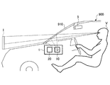
図1は、第1の実施の形態に係る情報表示装置を例示する模式図である。図1を参照するに、情報表示装置1は、自車両900に搭載されている。情報表示装置1は、所定の画像を視認者Vの前方のフロントウィンドシールド910に投影し、視認者Vの視界に虚像Iとして重畳して表示する機能を有する、所謂ヘッドアップディスプレイ(以下、HUDとする)である。なお、視認者Vは、ここでは自車両900の乗員である運転者である。フロントウィンドシールド910は、入射光の一部を透過させ、残部の少なくとも一部を反射させる透過反射部材としても機能する。<First Embodiment>
[Outline of information display device]
FIG. 1 is a schematic view illustrating the information display device according to the first embodiment. Referring to FIG. 1, the information display device 1 is mounted on a
情報表示装置1は、自車両900のインテリアデザインに準拠して任意の位置に配置してよく、例えば、自車両900内のダッシュボード上に配置することができる。情報表示装置1を自車両900のダッシュボード内に埋め込んでもよい。情報表示装置1は、主要な構成要素として、光学部10と、電気部20とを有している。
The information display device 1 may be arranged at any position according to the interior design of the
但し、本実施の形態では、情報表示装置1を自車両900に搭載する例を示すが、これには限定されない。情報表示装置1は、例えば、車両、航空機、船舶、産業用ロボット等の移動体に搭載され、移動体のフロントウィンドシールドを介して、移動体の操縦に必要なナビゲーション情報を視認可能にする。ここで、ナビゲーション情報とは、例えば、移動体の速度、進行方向、目的地までの距離、現在地名称、移動体前方における物体(現実物体)の有無や位置、制限速度等の標識、渋滞情報等の情報である。
However, in the present embodiment, an example in which the information display device 1 is mounted on the
情報表示装置1の投射方式としては、パネル方式やレーザ走査方式を採用することができる。パネル方式は、液晶パネル、DMDパネル(デジタルミラーデバイスパネル)、蛍光表示管(VFD)等のイメージングデバイスで中間像を形成する方式である。一方、レーザ走査方式は、レーザ光源から射出されたレーザビームを2次元走査デバイスで走査し中間像を形成する方式である。 As a projection method of the information display device 1, a panel method or a laser scanning method can be adopted. The panel method is a method of forming an intermediate image with an imaging device such as a liquid crystal panel, a DMD panel (digital mirror device panel), a fluorescent display tube (VFD) or the like. On the other hand, the laser scanning method is a method in which a laser beam emitted from a laser light source is scanned by a two-dimensional scanning device to form an intermediate image.
レーザ走査方式は、全画面発光の部分的遮光で画像を形成するパネル方式とは違い、各画素に対して発光/非発光を割り当てることができるため、一般に高コントラストの画像を形成することができる点で好適である。本実施の形態では、情報表示装置1の投射方式としてレーザ走査方式を採用する例を示すが、これには限定されない。 The laser scanning method can allocate light emission/non-light emission to each pixel, unlike a panel method in which an image is formed by partially shielding the entire screen light emission, and thus a high-contrast image can be generally formed. It is suitable in that respect. In the present embodiment, an example in which the laser scanning method is adopted as the projection method of the information display device 1 is shown, but the present invention is not limited to this.
図1において、情報取得部5は、虚像Iが表示される領域の背景輝度を取得し、情報表示装置1に送ることができる。但し、情報取得部5は、情報表示装置1の構成要素ではない。
In FIG. 1, the
情報取得部5は、視認者Vから見て虚像Iと重なる風景を含めた、自車両900の前方風景を画角に捉える形態で配置されている。情報取得部5は、自車両900のインテリアデザインに準拠して任意の位置に配置してよく、例えば、自車両900内の天井部に配置することができる。情報取得部5を自車両900内のダッシュボード上等に配置してもよい。
The
情報取得部5は、例えば、単眼カメラ、複眼カメラ(ステレオカメラ)、複数のカメラ画像を合成した全方位カメラ等である。情報取得部5は、背景輝度の取得以外に、ドライブレコーダやセンシングとして用いられてもよい。センシングの用途としては、例えば、前方車両や人間、標識等の検出や障害物までの距離の検知等を挙げることができる。
The
言い換えれば、情報取得部5は、情報表示装置1専用でなくてもよく、ドライブレコーダ等に用いられているものを利用すればよい。但し、情報表示装置1専用の情報取得部5を設けることを否定するものではない。
In other words, the
図2は、第1の実施の形態に係る情報表示装置の光学部の構成を例示する図である。図2を参照するに、光学部10は、大略すると、光源部101と、光偏向器102と、ミラー103と、スクリーン104と、凹面ミラー105とを有している。
FIG. 2 is a diagram illustrating the configuration of the optical unit of the information display device according to the first embodiment. Referring to FIG. 2, the
光学部10からフロントウィンドシールド910に対して画像を形成する光(画像光)を照射することにより、視認者Vの視点位置E(左右の目の中間点)から画像の虚像Iを視認可能にすることができる。つまり、視認者Vは、光学部10のスクリーン104に形成(描画)される画像(中間像)を、フロントウィンドシールド910を介して虚像Iとして視認することができる。この中間像は、視認者Vに対して情報を提供するための情報提供画像である。
By irradiating the
以下、光学部10の構成例について詳しく説明する。光源部101は、例えば、RGBに対応した3つのレーザ光源(以下、LDとする)、カップリングレンズ、アパーチャ、合成素子、レンズ等を備えており、3つのLDから出射されたレーザビームを合成して光偏向器102の反射面に向かって導く。光偏向器102の反射面に導かれたレーザビームは、光偏向器102により2次元的に偏向される。
Hereinafter, a configuration example of the
光偏向器102としては、例えば、直交する2軸に対して揺動する1つの微小なミラーや、1軸に揺動又は回動する2つの微小なミラー等を用いることができる。光偏向器102は、例えば、半導体プロセス等で作製されたMEMS(Micro Electro Mechanical Systems)とすることができる。光偏向器102は、例えば、圧電素子の変形力を駆動力とするアクチュエータにより駆動することができる。光偏向器102として、ガルバノミラーやポリゴンミラー等を用いてもよい。
As the
光偏向器102により2次元的に偏向されたレーザビームは、ミラー103に入射し、ミラー103により折り返され、スクリーン104の表面(被走査面)上に2次元の画像(中間像)を描画する。ミラー103としては、例えば凹面鏡を用いることができるが、凸面鏡や平面鏡を用いてもよい。スクリーン104としては、レーザビームを所望の発散角で発散させる機能を有するマイクロレンズアレイやマイクロミラーアレイを用いると好適であるが、レーザビームを拡散させる拡散板、表面が平滑な透過板や反射板等を用いてもよい。
The laser beam two-dimensionally deflected by the
スクリーン104から射出されたレーザビームは、凹面ミラー105で反射され、フロントウィンドシールド910に入射する。フロントウィンドシールド910への入射光束の一部はフロントウィンドシールド910を透過し、残部の少なくとも一部は視点位置Eに向けて反射される。この結果、視認者Vはフロントウィンドシールド910を介して中間像の拡大された虚像Iを視認可能となる、すなわち、視認者Vから見て虚像Iがフロントウィンドシールド910越しに拡大表示される。
The laser beam emitted from the
通常、フロントウィンドシールド910は、平面ではなく僅かに湾曲している。このため、凹面ミラー105とフロントウィンドシールド910の曲面とにより、虚像Iの結像位置が決定される。凹面ミラー105の集光パワーは、視認者Vの視点位置Eから虚像Iの結像位置までの距離Lが4m以上かつ10m以下(好ましくは6m以下)の位置(奥行位置)に表示されるように設定されることが好ましい。
Normally, the
又、ミラー103及び凹面ミラー105の少なくとも一方は、フロントウィンドシールド910の影響で中間像の水平線が上又は下に凸形状となる光学歪み要素を補正するように設計、配置されることが好ましい。
Further, at least one of the
なお、フロントウィンドシールド910よりも視点位置E側に透過反射部材としてコンバイナを配置してもよい。コンバイナに凹面ミラー105からの光を照射するようにしても、フロントウィンドシールド910に凹面ミラー105からの光を照射した場合と同様に、虚像Iを表示することができる。
A combiner may be arranged as a transflective member on the viewpoint position E side of the
図3は、第1の実施の形態に係る情報表示装置のハードウェア構成を例示するブロック図である。図3を参照するに、電気部20は、FPGA201と、CPU202と、ROM203と、RAM204と、I/F205と、バスライン206と、LDドライバ207と、MEMSコントローラ208とを有している。FPGA201、CPU202、ROM203、RAM204、及びI/F205は、バスライン206を介して相互に接続されている。
FIG. 3 is a block diagram illustrating the hardware configuration of the information display device according to the first embodiment. With reference to FIG. 3, the
FPGA201は、LDドライバ207を介して光学部10の光源部101のLDを駆動する。又、FPGA201は、MEMSコントローラ208を介して光学部10の光偏向器102を動作させる。
The
CPU202は、情報表示装置1の各機能を制御する。ROM203は、CPU202が情報表示装置1の各機能を制御するために実行するプログラムを記憶している。RAM204は、CPU202のワークエリアとして使用される。I/F205は、外部コントローラ等と通信するためのインターフェイスであり、例えば、自動車のCAN(Controller Area Network)等に接続される。
The
図4は、第1の実施の形態に係る情報表示装置の機能を例示するブロック図である。図4を参照するに、情報表示装置1は、情報入力部800、画像データ生成部820、及び画像描画部840を備えている。
FIG. 4 is a block diagram illustrating the function of the information display device according to the first embodiment. Referring to FIG. 4, the information display device 1 includes an
情報入力部800では、情報取得部5等からの情報が受信(入力)される。情報入力部800への受信は、有線であっても無線であってもよい。情報入力部800に、例えば、CAN等から車両の情報(速度、走行距離等の情報)や、外部ネットワークから車両外部の情報(GPSからのナビ情報や交通情報等)が入力されてもよい。情報入力部800に入力される情報には、前方車両等の現実物体の位置、大きさ、形、色、明るさの少なくとも1つを含むことができる。
The
画像データ生成部820は、情報入力部800から入力される情報に基づいて、描画すべき画像の画像データを生成する。画像データ生成部820は、データ調整部8210を備え、データ調整部8210は、画像データを生成する際に、表示する虚像の位置、大きさ、形、色、明るさ(輝度)の少なくとも1つを調整することができる。
The image
画像描画部840は、制御部8410を備え、制御部8410によって画像データに応じて光学部10が制御されることにより、フロントウィンドシールド910に光を照射する。結果として、視認者Vの視点位置Eから虚像Iが視認可能となる。
The
[3次元的な表示]
人間は、視界中の2次元的な見え方(絵画的手がかり)、両眼の見え方の差や目の焦点調節動作(動眼的手がかり)、視点移動時の物体の見え方の変化(運動視差)により空間の奥行きを知覚している。この中で、絵画的手がかりを主に利用することにより、情報表示装置1において、虚像である表示情報を、現実空間の任意の位置に存在するように知覚させることができる。[3D display]
Human beings have a two-dimensional appearance in the field of view (painting cues), the difference in the appearance of both eyes and the focus adjustment action of the eyes (moving eye cues), the change in the appearance of objects when moving the viewpoint (motion parallax). ) Perceives the depth of the space. Among these, by mainly utilizing the pictorial cues, it is possible to make the information display device 1 perceive the display information, which is a virtual image, as if it exists at an arbitrary position in the physical space.
現実空間では、同一の物体が存在した場合、その物体が視認者に距離が近ければ近い程、見かけ上の大きさは大きくなる。又、視認者に距離が近い物体ほど、視界中の下部に見える。他にも、遠い物体ほど、空気の厚みによりかすんで見えたりする。 In the physical space, when the same object exists, the closer the object is to the viewer, the larger the apparent size becomes. Also, the closer the object is to the viewer, the lower it can be seen in the field of view. In addition, the farther an object is, the more it looks hazy due to the thickness of the air.
情報表示装置1では、虚像は視認者の見る前方風景に重なって表示されるため、現実空間と整合するように虚像中の表示情報の幾何学形状を調整(幾何変換)すれば、表示情報の3次元的な表示が可能となる。すなわち、上記の人間の奥行き知覚を利用することで、視認者から視て、あたかも表示情報が現実空間の任意の位置に3次元的に存在しているように知覚(錯覚)させることが可能となる。 In the information display device 1, since the virtual image is displayed so as to overlap with the front scene viewed by the viewer, if the geometric shape of the display information in the virtual image is adjusted (geometric conversion) so as to match with the real space, the display information is displayed. A three-dimensional display is possible. That is, by utilizing the depth perception of the human, it is possible to make the viewer perceive (illusion) that the display information is three-dimensionally present at an arbitrary position in the real space as viewed from the viewer. Become.
このように、視認者から見て自車両の周囲に存在する現実物体と3次元的に整合する表示情報を表示することにより、表示情報の視認性を向上できる。なお、視認者から見て自車両の周囲に存在する現実物体と3次元的に整合する虚像と、視認者から見て現実物体と3次元的に整合しない虚像を表示可能領域内に混在させて表示してもよい。 In this way, by displaying the display information that is three-dimensionally matched with the physical object existing around the own vehicle as seen by the viewer, the visibility of the display information can be improved. It should be noted that a virtual image that three-dimensionally matches a real object that exists around the vehicle as seen by the viewer and a virtual image that does not three-dimensionally match the real object as seen by the viewer are mixed in the displayable area. It may be displayed.
ところで、情報表示装置1の表示像(虚像)は設計時に決定される位置に2次元的に投影される。そのため、現実空間の任意の位置、例えば視認者の視点の先の路面に存在するように形状や色合いを調整しても、左右の目それぞれの網膜には虚像が表示される位置に応じた映りの差、視差が生じてしまう。 By the way, the display image (virtual image) of the information display device 1 is two-dimensionally projected at a position determined at the time of design. Therefore, even if the shape and color are adjusted so that they exist on an arbitrary position in the real space, for example, on the road surface beyond the point of view of the viewer, the images corresponding to the positions where the virtual images are displayed on the retinas of the left and right eyes. Difference and parallax will occur.
ここで、図5に示すように、前方風景の遠方地点が視認者の目に映る際の視差を表す両目の視線が成す角度(輻輳角)をθSCENEとし、情報表示装置1の虚像が視認者の目に映る際の視差を表す両目の視線が成す角度(輻輳角)をθHUDとする。このとき、|θHUD−θSCENE|を「視差角」と定義する。なお、一般に「輻輳角」とは、視認者が視認対象を見るときの両目の視線が成す角度を意味する。Here, as shown in FIG. 5, the angle (convergence angle) formed by the lines of sight of both eyes, which represents the parallax when the distant point of the forward landscape is reflected in the eyes of the viewer, is θ SCENE, and the virtual image of the information display device 1 is visually recognized. Let θ HUD be the angle (convergence angle) formed by the lines of sight of both eyes, which represents the parallax when reflected by the human eye. At this time, |θ HUD −θ SCENE | is defined as “parallax angle”. In addition, in general, the “convergence angle” means an angle formed by the lines of sight of both eyes when a viewer views a target to be viewed.
この「視差角」が1°を超えると、二重像が知覚され、不快感や疲労感が増してしまう。そこで、情報表示装置1では、この「視差角」が1°以下となるように設計することが好ましい。「視差角」を1°以下とすることにより、情報表示装置1において、例えば、距離L(図2参照)を4m〜6mに設定した場合、1000m程度先の物体に対しても、前方風景に存在する対象物を見たまま視差なく虚像による情報を認知することが可能となる。 If this “parallax angle” exceeds 1°, a double image will be perceived, and discomfort and fatigue will increase. Therefore, the information display device 1 is preferably designed so that the “parallax angle” is 1° or less. By setting the “parallax angle” to be 1° or less, in the information display device 1, for example, when the distance L (see FIG. 2) is set to 4 m to 6 m, even if the object about 1000 m ahead, the forward scenery is displayed. It is possible to recognize information based on a virtual image without parallax while looking at an existing object.
[風景の奥行きの変化と虚像の制御]
虚像を重畳する風景位置の奥行きが変化した場合に、常に視認者の視点から見た前方の奥行きの変化に合わせて虚像の制御を行うと、風景における虚像の重畳位置によっては、視認者の視認性を損なわせてしまう場合がある。そこで、本実施の形態では、虚像を重畳する風景位置の奥行きが変化した場合に、表示する虚像の一部若しくは全部の変化度合いを、風景位置の奥行きの変化度合いと異なるように制御する。これについて、図面を参照して説明する。なお、『虚像を重畳する風景位置の奥行き』とは、視認者の視点から虚像を重畳する風景位置までの距離のことである。[Change of landscape depth and control of virtual image]
When the depth of the landscape position where the virtual image is superimposed changes, if the virtual image is always controlled according to the change in the depth in front of the viewer, depending on the overlapping position of the virtual image in the landscape, the viewer's visual It may impair the sex. Therefore, in the present embodiment, when the depth of the landscape position where the virtual image is superimposed changes, the change degree of part or all of the virtual image to be displayed is controlled so as to be different from the change degree of the depth of the landscape position. This will be described with reference to the drawings. The "depth of the landscape position where the virtual image is superimposed" is the distance from the viewpoint of the viewer to the landscape position where the virtual image is superimposed.
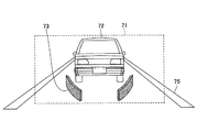
図6及び図7は、風景上の重畳位置の奥行きが遠いときの虚像表示について説明する図であり、HUDを介して視認者(運転者)から見える自車両前方の車両を追従するマーカを虚像として投影する状況を例示している。 FIG. 6 and FIG. 7 are views for explaining virtual image display when the depth of the superimposed position on the landscape is distant, and the virtual image of the marker that follows the vehicle ahead of the own vehicle that is visible to the viewer (driver) via the HUD. It illustrates the situation of projecting as.
図6及び図7において、マーカ73は、自車両と同じ車線上の道路75を走行する前方車両72を、ウィンドシールド上の虚像を投影可能な表示可能領域71内で追従している。
6 and 7, the
図6では、重畳させるマーカ73の大きさの変化度合いを、前方車両72の奥行きの変化度合いに合わせるように、前方車両72の奥行きの変化と同じ度合い(変化率)でマーカ73の縦方向の幅を変化させている(なお、マーカ73の横方向の幅は、前方車両72の車幅と合わせるように変化させている)。
In FIG. 6, in order to match the degree of change of the size of the
一方、図7では、重畳させるマーカ73の大きさの変化度合いを、前方車両72の奥行きの変化の度合いより小さくし、マーカ73の大きさの変化率を抑制して、図6のマーカ73より太く表示している(なお、マーカ73の横方向の幅は、前方車両72の車幅と合わせるように変化させている)。そのため、図7では、図6よりも前方車両の追従状況が視認し易くなる。
On the other hand, in FIG. 7, the degree of change in the size of the
図8及び図9は、風景上の重畳位置の奥行きが近いときの虚像表示について説明する図であり、図6及び図7と同様に、HUDを介して視認者(運転者)から見える自車両前方の車両を追従するマーカを虚像として投影する状況を例示している。 FIG. 8 and FIG. 9 are views for explaining the virtual image display when the depth of the superimposed position on the landscape is close, and similar to FIGS. 6 and 7, the own vehicle seen from the viewer (driver) via the HUD. It illustrates a situation in which a marker that follows a vehicle ahead is projected as a virtual image.
図8では、重畳させるマーカ73の大きさの変化度合いを、前方車両72の奥行きの変化度合いに合わせるように、前方車両72の奥行きの変化と同じ度合い(変化率)でマーカ73の縦方向の幅を変化させている(なお、マーカ73の横方向の幅は、前方車両72の車幅と合わせるように変化させている)。
In FIG. 8, in order to match the degree of change of the size of the
一方、図9では、重畳させるマーカ73の大きさの変化度合いを、前方車両72の奥行きの変化の度合いより小さくし、マーカ73の大きさの変化率を抑制して、図8のマーカ73より細く表示している(なお、マーカ73の横方向の幅は、前方車両72の車幅と合わせるように変化させている)。そのため、図9では、図8のような過度な表示に伴って視認者(運転者)の注意が必要以上に引き付けられるおそれを低減できる。
On the other hand, in FIG. 9, the degree of change in the size of the
図10は、風景上の重畳位置の奥行きの違いによる虚像の輝度の変化について説明する図であり、図6〜図9と同様に、HUDを介して視認者(運転者)から見える自車両前方の車両を追従するマーカを虚像として投影する状況を例示している。 FIG. 10 is a diagram for explaining the change in the brightness of the virtual image due to the difference in the depth of the superimposed position on the landscape, and similar to FIGS. 6 to 9, the front of the own vehicle seen from the viewer (driver) via the HUD. 3 illustrates a situation in which the marker that follows the vehicle is projected as a virtual image.
図10では、重畳させるマーカ73の輝度の変化度合いを、前方車両72の奥行きの変化度合いに合わせるように、前方車両72の奥行きの変化と同じ度合い(変化率)でマーカ73の輝度を変化させている(なお、マーカ73の横方向及び縦方向の幅の制御については、図7と同様である)。
In FIG. 10, the brightness of the
一方、図11では、重畳させるマーカ73の輝度の変化度合いを、前方車両72の奥行きの変化の度合いより大きくし、マーカ73の輝度の変化率を拡大して、図10のマーカ73より輝度を高くして表示している(なお、マーカ73の横方向及び縦方向の幅の制御については、図9と同様である)。なお、図10及び図11においては、便宜上、高輝度を黒色で表現している。
On the other hand, in FIG. 11, the degree of change in the brightness of the
このように、風景上の重畳位置の奥行きの遠近に合わせてマーカ73の輝度を調整することで、追従している前方車両の遠近感を適切に表現できる。
In this way, by adjusting the brightness of the
図10のように、前方車両72が自車両より遠く、知覚すべき優先度が低いと判断させるような状態では、他の優先度が高い虚像表示を妨げないように輝度を低くすると有効である。一方、図11のように、前方車両72が自車両に近く、接触のおそれがある状態では、その危険性を運転者に視認し易くするために輝度を高くすると有効である。
As shown in FIG. 10, in a state where the
但し、虚像を重畳する風景位置の奥行きが遠い場合(例えば、虚像を重畳する風景位置の奥行きが後述の閾値TH2よりも遠い場合)には、虚像の輝度を奥行きの変化度合いにかかわらず一定値以下に落とさないように制御しても良い。遠方の重要度が低い情報であっても、輝度を低くしすぎると路面上の、例えばごみ等と誤認するおそれがあり、これを防止するためである。 However, when the depth of the landscape position where the virtual image is superimposed is far (for example, when the depth of the landscape position where the virtual image is superimposed is farther than a threshold value TH2 described later), the brightness of the virtual image is a constant value regardless of the degree of change in depth. You may control not to drop below. This is because even if the information is of low importance in the distance, if the brightness is too low, it may be erroneously recognized as dust on the road surface, for example.
なお、図6〜図11に示したように、マーカの形成変化は、風景上の重畳位置の奥行きの遠近に合わせて拡大縮小させるような相似変化には限らない。これについて、三角形状のマーカ74を例にとり、図12を参照して補足説明する。
Note that, as shown in FIGS. 6 to 11, the marker formation change is not limited to the similar change in which the marker is enlarged or reduced in accordance with the perspective of the depth of the superimposed position on the landscape. This will be supplementarily described with reference to FIG. 12 using the
図12(a)は、三角形状のマーカ74について、風景上の重畳位置の奥行きが近いときの虚像表示を表している。図12(b)は、三角形状のマーカ74Aについて、風景上の重畳位置の奥行きが遠いときの虚像表示を表している。図12(b)のマーカ74Aと図12(a)のマーカ74とは相似関係である。
FIG. 12A shows a virtual image display of the
図12(c)は、三角形状のマーカ74Bの形成変化について、風景上の重畳位置の奥行きの変化度合いに対して、相似変化でない場合を示している。図12(c)では、横方向の幅l1は奥行きが遠いときは大きく、奥行きが近いとき小さく変化させ、遠近法に合わせて変形させている。一方、縦方向の幅l2'は、遠近法の奥行きの変化度合いによらず、一定の大きさ以下にしないよう保つように表示している。FIG. 12C shows a case where the formation change of the
このように、奥行きの変化度合いに応じたマーカの形成変化の仕方は、拡大や縮小といった相似変化に限られない。 As described above, the method of forming and changing the marker according to the degree of change in depth is not limited to the similar change such as enlargement or reduction.
なお、図6〜図11では、マーカ73として自車両前方の車両を追従する図形を表示する例を示したが、マーカ73は自車両前方の車両を追従する図形には限定されず、例えば、行き先案内のための進路を表す矢印等であってもよい。又、表示する虚像は、1つである必要はなく、複数であってもよい。この場合、視認者から見て自車両の周囲に存在する現実物体と3次元的に整合する虚像と、視認者から見て現実物体と3次元的に整合しない虚像を表示可能領域71内に混在させて表示してもよい。
6 to 11, an example in which a figure that follows the vehicle in front of the own vehicle is displayed as the
図13は、風景位置の奥行きの変化度合いと虚像の形状の変化度合いの相関について説明する図であり、図6〜図11と同様に、HUDを介して視認者(運転者)から見える自車両前方の車両を追従するマーカを虚像として投影する状況を例にしている。 FIG. 13 is a diagram for explaining the correlation between the degree of change in the depth of the landscape position and the degree of change in the shape of the virtual image. Similar to FIGS. 6 to 11, the own vehicle seen from the viewer (driver) via the HUD. An example is shown in which a marker that follows a vehicle ahead is projected as a virtual image.
図13では、横軸を奥行きの変化度合い、縦軸を形状の変化度合いとして表し、虚像の変化を拡大と縮小だけで表現している。 In FIG. 13, the horizontal axis represents the degree of change in depth and the vertical axis represents the degree of change in shape, and changes in the virtual image are represented only by enlargement and reduction.
まず、奥行きの変化度合いにおける近辺の閾値TH1から遠方の閾値TH2まで(閾値TH1及びの閾値TH2も含む)の形状の変化度合いは、運転者の視認性が低下しないと仮定して、従来手法と同様に奥行きの変化度合いに比例して(合わせて)変化させる。つまり、虚像を重畳する風景位置の奥行きが閾値TH1以上閾値TH2以下の場合には、表示する虚像の一部若しくは全部の変化度合いを、奥行きの変化度合いと合わせるように制御する。 First, the degree of change in shape from the near threshold TH1 to the far threshold TH2 (including the threshold TH1 and the threshold TH2) in the depth change degree is assumed to be the same as that of the conventional method, assuming that the visibility of the driver does not decrease. Similarly, the depth is changed in proportion (together). That is, when the depth of the landscape position on which the virtual image is superimposed is greater than or equal to the threshold value TH1 and less than or equal to the threshold value TH2, the degree of change of part or all of the displayed virtual image is controlled to match the degree of change of the depth.
これに対して、奥行きの変化度合いにおいて、運転者に虚像を提示させる最も奥行きが近い所から近辺の閾値TH1までは、虚像が過度に拡大されることにより注意が必用以上に向けられることを防ぐため、近辺の閾値TH1まで形状の変化度合いを一定に保ち、奥行きの変化度合いと異なるように表示させる。 On the other hand, with respect to the degree of change in depth, it is possible to prevent the virtual image from being excessively enlarged to draw attention more than necessary from a position where the virtual image is presented to the driver to the closest depth to a threshold value TH1 in the vicinity. Therefore, the degree of change in shape is kept constant up to the threshold value TH1 in the vicinity, and the degree of change in depth is displayed differently.
又、奥行きの変化度合いにおいて、遠方の閾値TH2から運転者に提示させる最遠方の表示距離までは、虚像が過度に縮小されることにより視認が困難になることを防ぐため、遠方の閾値TH2から形状の変化度合いを一定に保ち、奥行きの変化度合いと異なるように表示させる。 Further, in the degree of change in depth, from the far threshold TH2 to the farthest display distance to be presented to the driver from the far threshold TH2 in order to prevent the virtual image from being excessively reduced and making it difficult to be visually recognized. The degree of change in shape is kept constant and displayed differently from the degree of change in depth.
このように、情報表示装置1では、遠近法で見る車両前方の風景の変化の度合いと、重畳する虚像の制御対象部分(例えば、虚像の縦方向の大きさや輝度)の変化度合いを異なるように制御することで、視認者の視認性を損なわずに虚像を表示することができる。例えば、遠近法で見る車両前方の風景の変化度合いが大きくても、視認者の知覚の妨げにならないように虚像を表示することができる。 As described above, in the information display device 1, the degree of change in the landscape in front of the vehicle viewed by the perspective method and the degree of change in the control target portion of the virtual image to be superimposed (for example, the vertical size and brightness of the virtual image) are made different. By controlling, the virtual image can be displayed without impairing the visibility of the viewer. For example, a virtual image can be displayed so as not to interfere with the perception of the viewer even if the degree of change in the scenery in front of the vehicle viewed in perspective is large.
特に、奥行きの変化度合いが所定の範囲外(虚像を重畳する風景位置の奥行きが閾値TH1よりも近い場合及び閾値TH2よりも遠い場合)において、表示する虚像の一部若しくは全部の変化度合いを、奥行きの変化度合いと異なるように制御し、奥行きの変化度合いが所定の範囲内(虚像を重畳する風景位置の奥行きが閾値TH1以上閾値TH2以下の場合)において、表示する虚像の一部若しくは全部の変化度合いを、奥行きの変化度合いと合わせるように制御することが好ましい。 In particular, when the degree of change in depth is outside a predetermined range (when the depth of the landscape position where the virtual image is superimposed is closer than the threshold TH1 and farther than the threshold TH2), the degree of change of part or all of the virtual image to be displayed is When the depth change degree is controlled to be different from the depth change degree within a predetermined range (when the depth of the landscape position on which the virtual image is superimposed is greater than or equal to the threshold TH1 and less than or equal to the threshold TH2), a part or all of the virtual image to be displayed is displayed. It is preferable to control the degree of change to match the degree of change in depth.
なお、奥行きの変化度合いは、情報取得部5からの距離等の情報を情報入力部800に入力することで得ることができ、マーカ73の幅や輝度等の制御は、入力された情報に基づいて、データ調整部8210により行うことができる。或いは、GPS等からの情報を情報入力部800に入力し、入力された情報に基づいて、データ調整部8210により制御を行ってもよい。
The degree of change in depth can be obtained by inputting information such as the distance from the
例えば、図13のグラフに対応するテーブルをROM203に記憶しておき、データ調整部8210が、入力された情報とROM203に記憶されたテーブルにより、マーカ73の幅や輝度等の制御を行うことができる。
For example, a table corresponding to the graph of FIG. 13 is stored in the
なお、以上で説明した風景の奥行きの変化と虚像の制御は、風景と切り離した情報表示装置1単体での動作として捉えると、フロントウィンドシールド910に投影する画像を上下方向に移動させたときに、表示する画像の幾何学的形状を変化させることである。或いは、フロントウィンドシールド910に投影する画像を上下方向に移動させたときに、表示する画像の輝度を変化させることである。或いは、フロントウィンドシールド910に投影する画像を上下方向に移動させたときに、表示する画像の幾何学的形状及び輝度を変化させることである。
When the change in the depth of the landscape and the control of the virtual image described above are regarded as the operation of the information display device 1 alone separated from the landscape, when the image projected on the
又、フロントウィンドシールド910に投影する画像を上下方向に移動させたときに、表示する画像の幾何学的形状を変化させる場合、図13のように画像の上下方向の移動量(図13の横軸に相当)に対する幾何学的形状の変化度合いが異なる部分を有してもよい。例えば、図13の閾値TH1以上閾値TH2以下の部分と、閾値TH1より小さい部分及び閾値TH2よりも大きい部分のように、幾何学的形状の変化度合いが異なる部分を有してもよい。但し、図13において、閾値TH1より小さい部分及び閾値TH2よりも大きい部分は、閾値TH1以上閾値TH2以下の部分よりも小さな傾斜を有するようにしてもよい。なお、ここでいう上下方向とは、重力方向によって決定される方向である。
Further, when the image projected on the
[物体情報の受信]
情報表示装置1では、視認者の視点位置、虚像位置、視点と虚像との距離、虚像の大きさ、虚像の重畳を行いたい範囲に基づいて、表示する像を決定する。例えば、路面に虚像の重畳を行う場合は、重畳を行いたい位置・距離を任意に決定し、視認者の視点から見て、目的の位置・距離に存在して見えるように幾何変換を行った表示を行うことができる。[Reception of object information]
In the information display device 1, the image to be displayed is determined based on the viewpoint position of the viewer, the virtual image position, the distance between the viewpoint and the virtual image, the size of the virtual image, and the range in which the virtual image is desired to be superimposed. For example, when superimposing a virtual image on the road surface, the position/distance to be superimposed is arbitrarily determined, and geometric transformation is performed so that it can be seen at the target position/distance from the viewpoint of the viewer. The display can be done.
路面が平面であることを仮定して虚像の表示を行う場合は、幾何変換を行うのみで表示が可能であるが、カーブや坂道といった路面形状に対応させる場合や、白線に重ねた表示 を行う場合等は、物体情報の取得が必要となる。物体情報とは、例えば、路面において重畳させる位置の座標(位置情報)である。又、前方車両や歩行者等の対象に重畳を行う場合は、これらの対象の位置情報である。又、これら以外の、物体に関する情報であってもよい。 When displaying a virtual image assuming that the road surface is a flat surface, it can be displayed only by performing geometric transformation, but when it corresponds to a road surface shape such as a curve or a slope, or it is displayed overlaid on a white line. In some cases, acquisition of object information is required. The object information is, for example, coordinates (position information) of a position to be superimposed on the road surface. When superimposing on a target such as a vehicle in front or a pedestrian, the position information of these targets is used. Information other than the above may be information about the object.
情報取得部5として、例えば、レーザレーダを用いることにより、物体情報として位置情報を取得することができる。レーザレーダは、レーザビームを出射し、物体(例えば、先行車両、停車車両、構造物、歩行者等)からの反射光(散乱光)を受光することで、位置情報(物体までの距離や物体の座標)を測定する装置である。
By using, for example, a laser radar as the
情報取得部5として、ステレオカメラを用いてもよい。ステレオカメラは、左目用となるカメラ部と、右目用となるカメラ部とを備えており、両カメラ部から得られる視差画像から物体の3次元位置情報を算出することができる。
A stereo camera may be used as the
情報表示装置1は、情報取得部5からの物体情報(例えば物体の3次元位置情報)を情報入力部800で受信し、受信した物体情報を画像データ生成部820に送る。画像データ生成部820は、物体情報に基づいて、表示情報(虚像)のパラメータ(虚像の結像位置、大きさ、形、色、明るさの少なくとも1つ)を調整する。現実物体と3次元的に整合する表示情報を表示する場合には、虚像のパラメータは、現実物体の位置、形、大きさに応じた遠近感が出るように調整されることが好ましい。
In the information display device 1, the
なお、情報表示装置1は、例えば、交通情報(例えば、渋滞情報や交通ルール等)や気象情報等の情報を情報入力部800で受信し、受信した情報を、現実物体と3次元的に整合するように虚像として表示してもよい。
The information display device 1 receives, for example, information such as traffic information (for example, traffic congestion information, traffic rules, etc.), weather information, and the like at the
又、情報表示装置1は、例えば、自車両の位置情報を情報入力部800で受信し、受信した情報を、現実物体と3次元的に整合するように虚像として表示してもよい。自車両の位置情報は、例えばGPSを搭載した装置(例えば、カーナビゲーションシステム)から受信することができる。
Further, the information display device 1 may receive, for example, the position information of the own vehicle by the
以上、好ましい実施の形態について詳説したが、上述した実施の形態に制限されることはなく、視認者に対して提供するあらゆる情報を表示する際に適用できるものである。特許請求の範囲に記載された範囲を逸脱することなく、上述した実施の形態に種々の変形及び置換を加えることができる。 Although the preferred embodiment has been described in detail above, the present invention is not limited to the above-described embodiment, and can be applied when displaying all information provided to the viewer. Various modifications and substitutions can be made to the above-described embodiment without departing from the scope of the claims.
本国際出願は2016年2月8日に出願した日本国特許出願2016−021593号に基づく優先権を主張するものであり、日本国特許出願2016−021593号の全内容を本国際出願に援用する。 This international application claims priority based on Japanese Patent Application No. 2016-021593 filed on February 8, 2016, and the entire content of Japanese Patent Application No. 2016-021593 is incorporated into the present international application. ..
1 情報表示装置
10 光学部
20 電気部
71 表示可能領域
72 前方車両
73、74、74A、74B マーカ
75 道路
101 光源部
102 光偏向器
103 ミラー
104 スクリーン
105 凹面ミラー
201 FPGA
202 CPU
203 ROM
204 RAM
205 I/F
206 バスライン
207 LDドライバ
208 MEMSコントローラ
800 情報入力部
820 画像データ生成部
840 画像描画部
8210 データ調整部
8410 制御部DESCRIPTION OF SYMBOLS 1
202 CPU
203 ROM
204 RAM
205 I/F
206
Claims (12)
前記虚像の視認者の視点位置から前記虚像が重畳される風景位置までの距離が変化した場合に、
前記距離が所定の範囲内において、前記虚像の縦方向の大きさの変化度合い及び前記虚像の横方向の大きさの変化度合いを前記距離の変化度合いと合わせるように制御し、
前記距離が所定の範囲外において、前記虚像の縦方向の大きさの変化度合いが前記距離の変化度合いよりも小さくなるように制御し、前記虚像の横方向の大きさの変化度合いを前記距離の変化度合いと合わせるように制御することを特徴とする情報表示装置。 An information display device which irradiates light for forming an image onto a transmissive/reflective member and visually recognizes a virtual image of the image through the transmissive/reflective member,
When the distance from the viewer's viewpoint position of the virtual image to the landscape position where the virtual image is superimposed changes,
Within the distance is predetermined to control the vertical degree of change size and lateral size degree of change of the virtual image of the virtual image to match the degree of change in the distance,
When the distance is outside a predetermined range, the degree of change in the vertical size of the virtual image is controlled to be smaller than the degree of change in the distance, and the degree of change in the horizontal size of the virtual image is set to An information display device characterized by being controlled so as to match the degree of change.
前記物体情報に基づいて、前記視認者から見て前記現実物体と3次元的に整合するように前記交通情報を前記表示可能領域内に前記虚像として表示することを特徴とする請求項8乃至10の何れか一項に記載の情報表示装置。 The information input unit further receives traffic information related to the mobile body,
On the basis of the object information, according to claim 8 to 10, characterized in that displaying the traffic information to the real object and the three-dimensionally aligned when viewed from the viewer as the virtual image to the displayable region The information display device according to any one of 1.
前記位置情報に基づいて、前記視認者から見て前記現実物体と3次元的に整合するように前記虚像を表示可能領域内に表示することを特徴とする請求項8乃至11の何れか一項に記載の情報表示装置。 The information input unit further receives position information of the moving body,
Based on the position information, any one of claims 8 to 11 and displaying the displayable area of the virtual image to the real object and the three-dimensionally aligned when viewed from the viewer Information display device described in.
Applications Claiming Priority (3)
| Application Number | Priority Date | Filing Date | Title |
|---|---|---|---|
| JP2016021593 | 2016-02-08 | ||
| JP2016021593 | 2016-02-08 | ||
| PCT/JP2017/003780 WO2017138428A1 (en) | 2016-02-08 | 2017-02-02 | Information display apparatus |
Publications (2)
| Publication Number | Publication Date |
|---|---|
| JPWO2017138428A1 JPWO2017138428A1 (en) | 2018-11-29 |
| JP6741029B2 true JP6741029B2 (en) | 2020-08-19 |
Family
ID=59563478
Family Applications (1)
| Application Number | Title | Priority Date | Filing Date |
|---|---|---|---|
| JP2017566899A Active JP6741029B2 (en) | 2016-02-08 | 2017-02-02 | Information display device |
Country Status (4)
| Country | Link |
|---|---|
| US (1) | US10621776B2 (en) |
| EP (1) | EP3415972B1 (en) |
| JP (1) | JP6741029B2 (en) |
| WO (1) | WO2017138428A1 (en) |
Families Citing this family (11)
| Publication number | Priority date | Publication date | Assignee | Title |
|---|---|---|---|---|
| JP7098441B2 (en) * | 2018-06-29 | 2022-07-11 | 日精株式会社 | Mechanical parking system |
| GB2576060A (en) * | 2018-07-31 | 2020-02-05 | Continental Automotive Gmbh | Head-Up Display System |
| US11348316B2 (en) * | 2018-09-11 | 2022-05-31 | Apple Inc. | Location-based virtual element modality in three-dimensional content |
| JP7338632B2 (en) * | 2018-09-27 | 2023-09-05 | 日本精機株式会社 | Display device |
| WO2020144798A1 (en) * | 2019-01-10 | 2020-07-16 | 三菱電機株式会社 | Information display control device and method, and program and recording medium |
| JP7447820B2 (en) * | 2019-02-13 | 2024-03-12 | ソニーグループ株式会社 | Mobile objects, communication methods, and programs |
| JP7240208B2 (en) * | 2019-03-07 | 2023-03-15 | 株式会社豊田中央研究所 | VEHICLE DISPLAY DEVICE, VEHICLE DISPLAY METHOD, AND COMPUTER PROGRAM |
| JP7222285B2 (en) * | 2019-03-20 | 2023-02-15 | 株式会社リコー | DISPLAY CONTROL DEVICE, DISPLAY DEVICE, DISPLAY SYSTEM, MOBILE OBJECT, PROGRAM, IMAGE GENERATION METHOD |
| DE102020207314A1 (en) * | 2020-06-11 | 2021-12-16 | Volkswagen Aktiengesellschaft | Control of a display of an augmented reality head-up display device for a means of locomotion |
| KR20220022340A (en) * | 2020-08-18 | 2022-02-25 | 삼성전자주식회사 | Device and method to visualize content |
| GB2613004A (en) * | 2021-11-19 | 2023-05-24 | Wayray Ag | System and method |
Family Cites Families (42)
| Publication number | Priority date | Publication date | Assignee | Title |
|---|---|---|---|---|
| JP2002046501A (en) * | 2001-06-13 | 2002-02-12 | Hitachi Ltd | Running control device for automobile |
| JP2004058828A (en) | 2002-07-29 | 2004-02-26 | Denso Corp | Vehicle front display system |
| JP2006309090A (en) | 2005-02-21 | 2006-11-09 | Ricoh Co Ltd | Scanning optical system, optical scanner, image forming device, and color image forming apparatus |
| JP4500738B2 (en) | 2005-06-20 | 2010-07-14 | 株式会社リコー | Optical scanning device and image forming device |
| JP4887980B2 (en) | 2005-11-09 | 2012-02-29 | 日産自動車株式会社 | VEHICLE DRIVE OPERATION ASSISTANCE DEVICE AND VEHICLE WITH VEHICLE DRIVE OPERATION ASSISTANCE DEVICE |
| US7876486B2 (en) | 2006-03-08 | 2011-01-25 | Ricoh Company, Limited | Optical scanning apparatus, optical writing apparatus, and image forming apparatus |
| US7688491B2 (en) | 2006-09-15 | 2010-03-30 | Ricoh Company, Ltd. | Diffractive-optical element, scanning optical system, optical scanner, and image forming apparatus |
| JP4976092B2 (en) | 2006-09-19 | 2012-07-18 | 株式会社リコー | Optical scanning device and image forming apparatus using the same |
| US8045248B2 (en) | 2007-03-09 | 2011-10-25 | Ricoh Company, Ltd. | Optical scanning device and image forming apparatus |
| JP2009053379A (en) | 2007-08-27 | 2009-03-12 | Ricoh Co Ltd | Optical scanner and image forming apparatus |
| JP2009053378A (en) | 2007-08-27 | 2009-03-12 | Ricoh Co Ltd | Optical scanner and image forming apparatus |
| JP4852062B2 (en) | 2008-03-28 | 2012-01-11 | 株式会社東芝 | Monocular image display device and monocular image display method |
| JP2010188811A (en) * | 2009-02-17 | 2010-09-02 | Honda Motor Co Ltd | Information presenting device for vehicle |
| JP2011013289A (en) | 2009-06-30 | 2011-01-20 | Ricoh Co Ltd | Optical scanning device and image forming apparatus |
| US8531766B2 (en) | 2009-07-02 | 2013-09-10 | Ricoh Company, Limited | Polarization-separation device, optical scanning apparatus, and image forming apparatus |
| JP5679175B2 (en) | 2010-03-24 | 2015-03-04 | 株式会社リコー | Optical scanning apparatus and image forming apparatus |
| JP5691633B2 (en) | 2010-06-25 | 2015-04-01 | 株式会社リコー | Optical scanning apparatus and image forming apparatus |
| JP5803184B2 (en) | 2010-11-19 | 2015-11-04 | 株式会社リコー | Image projection apparatus and memory access method |
| EP2720929B1 (en) * | 2011-06-17 | 2016-04-27 | Robert Bosch GmbH | Method and device for assisting a driver in performing lateral guidance of a vehicle on a carriageway |
| JP2013061554A (en) | 2011-09-14 | 2013-04-04 | Ricoh Co Ltd | Image forming apparatus, and vehicle with image forming apparatus mounted thereon |
| DE112012005852T5 (en) * | 2012-02-10 | 2014-11-27 | Mitsubishi Electric Corporation | Driver assistance device and driver assistance method |
| JP5783155B2 (en) * | 2012-10-05 | 2015-09-24 | 株式会社デンソー | Display device |
| JP6237124B2 (en) | 2012-12-21 | 2017-11-29 | 株式会社リコー | Two-dimensional image display device, optical scanning device for two-dimensional image display device, scanned surface element, and moving body |
| US9158124B2 (en) | 2012-12-21 | 2015-10-13 | Ricoh Company, Ltd. | Image display device and vehicle incorporating the same |
| JP6237123B2 (en) | 2012-12-21 | 2017-11-29 | 株式会社リコー | Two-dimensional image display device, optical scanning device for two-dimensional image display device, scanned surface element, and moving body |
| JP5682692B2 (en) | 2012-12-21 | 2015-03-11 | 株式会社リコー | Image display device |
| JP6265140B2 (en) | 2012-12-21 | 2018-01-24 | 株式会社リコー | Microlens array and moving body |
| JP5983547B2 (en) | 2013-07-02 | 2016-08-31 | 株式会社デンソー | Head-up display and program |
| JP5786905B2 (en) | 2013-07-18 | 2015-09-30 | 株式会社リコー | Optical scanning apparatus and image forming apparatus |
| JP6138634B2 (en) * | 2013-08-29 | 2017-05-31 | アイシン・エィ・ダブリュ株式会社 | Head-up display device |
| JP6387589B2 (en) | 2013-08-30 | 2018-09-12 | 株式会社リコー | Image forming apparatus, vehicle, and control method of image forming apparatus |
| JP2015104930A (en) * | 2013-11-28 | 2015-06-08 | 株式会社デンソー | Head-up display device |
| JP5817855B2 (en) | 2014-01-22 | 2015-11-18 | 株式会社リコー | Optical scanning apparatus and image forming apparatus |
| JP6340807B2 (en) | 2014-02-05 | 2018-06-13 | 株式会社リコー | Image display device and moving body |
| JP6481846B2 (en) * | 2014-03-27 | 2019-03-13 | 日本精機株式会社 | Vehicle alarm device |
| JP6638198B2 (en) | 2014-05-12 | 2020-01-29 | 株式会社リコー | Image display device and moving object |
| JP6555507B2 (en) | 2014-05-12 | 2019-08-07 | 株式会社リコー | Image display device and moving body |
| JP6617947B2 (en) | 2014-05-15 | 2019-12-11 | 株式会社リコー | Image display device and image display system |
| JP6394940B2 (en) * | 2014-05-23 | 2018-09-26 | 日本精機株式会社 | Vehicle display system |
| US20170134662A1 (en) | 2014-07-01 | 2017-05-11 | Nissan Motor Co., Ltd. | Vehicular display apparatus and vehicular display method |
| JP6485732B2 (en) | 2014-12-10 | 2019-03-20 | 株式会社リコー | Information providing apparatus, information providing method, and information providing control program |
| EP3093194B1 (en) | 2015-04-24 | 2021-09-22 | Ricoh Company, Ltd. | Information provision device |
-
2017
- 2017-02-02 EP EP17750152.5A patent/EP3415972B1/en active Active
- 2017-02-02 WO PCT/JP2017/003780 patent/WO2017138428A1/en active Application Filing
- 2017-02-02 JP JP2017566899A patent/JP6741029B2/en active Active
-
2018
- 2018-07-26 US US16/046,203 patent/US10621776B2/en active Active
Also Published As
| Publication number | Publication date |
|---|---|
| JPWO2017138428A1 (en) | 2018-11-29 |
| EP3415972A1 (en) | 2018-12-19 |
| US20180330539A1 (en) | 2018-11-15 |
| EP3415972B1 (en) | 2021-03-31 |
| WO2017138428A1 (en) | 2017-08-17 |
| EP3415972A4 (en) | 2019-06-12 |
| US10621776B2 (en) | 2020-04-14 |
Similar Documents
| Publication | Publication Date | Title |
|---|---|---|
| JP6741029B2 (en) | Information display device | |
| US10551619B2 (en) | Information processing system and information display apparatus | |
| US10679496B2 (en) | Information providing apparatus | |
| JP6780663B2 (en) | Information display device | |
| JP2017211366A (en) | Mobile body system and information display device | |
| US10890762B2 (en) | Image display apparatus and image display method | |
| JP6834537B2 (en) | Display device, mobile device, manufacturing method and display method of display device. | |
| JP6930120B2 (en) | Display device, mobile device and display method. | |
| WO2020110580A1 (en) | Head-up display, vehicle display system, and vehicle display method | |
| WO2016190135A1 (en) | Vehicular display system | |
| WO2017094427A1 (en) | Head-up display | |
| WO2017141829A1 (en) | Information presentation device | |
| JP6504431B2 (en) | IMAGE DISPLAY DEVICE, MOBILE OBJECT, IMAGE DISPLAY METHOD, AND PROGRAM | |
| JP2018077400A (en) | Head-up display | |
| JP2021154988A (en) | On-vehicle display device, method of controlling on-vehicle display device, and computer program | |
| JP2021121536A (en) | Control device, image display method, and program | |
| JP7385834B2 (en) | Image display method and image display device | |
| JP2010224293A (en) | Display device, display method, and vehicle | |
| JP2022113292A (en) | Display control device, head-up display device, and display control method | |
| JP2021117987A (en) | Image display device, image display method, and program | |
| JP2021133804A (en) | On-vehicle display device, method for controlling on-vehicle display device, and computer program |
Legal Events
| Date | Code | Title | Description |
|---|---|---|---|
| A621 | Written request for application examination |
Free format text: JAPANESE INTERMEDIATE CODE: A621 Effective date: 20180801 |
|
| A131 | Notification of reasons for refusal |
Free format text: JAPANESE INTERMEDIATE CODE: A131 Effective date: 20190730 |
|
| A521 | Request for written amendment filed |
Free format text: JAPANESE INTERMEDIATE CODE: A523 Effective date: 20190927 |
|
| A131 | Notification of reasons for refusal |
Free format text: JAPANESE INTERMEDIATE CODE: A131 Effective date: 20200128 |
|
| A521 | Request for written amendment filed |
Free format text: JAPANESE INTERMEDIATE CODE: A523 Effective date: 20200326 |
|
| TRDD | Decision of grant or rejection written | ||
| A01 | Written decision to grant a patent or to grant a registration (utility model) |
Free format text: JAPANESE INTERMEDIATE CODE: A01 Effective date: 20200623 |
|
| A61 | First payment of annual fees (during grant procedure) |
Free format text: JAPANESE INTERMEDIATE CODE: A61 Effective date: 20200706 |
|
| R151 | Written notification of patent or utility model registration |
Ref document number: 6741029 Country of ref document: JP Free format text: JAPANESE INTERMEDIATE CODE: R151 |