JP6780663B2 - Information display device - Google Patents
Information display device Download PDFInfo
- Publication number
- JP6780663B2 JP6780663B2 JP2017566596A JP2017566596A JP6780663B2 JP 6780663 B2 JP6780663 B2 JP 6780663B2 JP 2017566596 A JP2017566596 A JP 2017566596A JP 2017566596 A JP2017566596 A JP 2017566596A JP 6780663 B2 JP6780663 B2 JP 6780663B2
- Authority
- JP
- Japan
- Prior art keywords
- information
- image
- display device
- displayed
- information display
- Prior art date
- Legal status (The legal status is an assumption and is not a legal conclusion. Google has not performed a legal analysis and makes no representation as to the accuracy of the status listed.)
- Active
Links
Images


Classifications
-
- B—PERFORMING OPERATIONS; TRANSPORTING
- B60—VEHICLES IN GENERAL
- B60K—ARRANGEMENT OR MOUNTING OF PROPULSION UNITS OR OF TRANSMISSIONS IN VEHICLES; ARRANGEMENT OR MOUNTING OF PLURAL DIVERSE PRIME-MOVERS IN VEHICLES; AUXILIARY DRIVES FOR VEHICLES; INSTRUMENTATION OR DASHBOARDS FOR VEHICLES; ARRANGEMENTS IN CONNECTION WITH COOLING, AIR INTAKE, GAS EXHAUST OR FUEL SUPPLY OF PROPULSION UNITS IN VEHICLES
- B60K35/00—Arrangement of adaptations of instruments
-
- G—PHYSICS
- G02—OPTICS
- G02B—OPTICAL ELEMENTS, SYSTEMS OR APPARATUS
- G02B27/00—Optical systems or apparatus not provided for by any of the groups G02B1/00 - G02B26/00, G02B30/00
- G02B27/01—Head-up displays
- G02B27/0101—Head-up displays characterised by optical features
-
- G—PHYSICS
- G02—OPTICS
- G02B—OPTICAL ELEMENTS, SYSTEMS OR APPARATUS
- G02B27/00—Optical systems or apparatus not provided for by any of the groups G02B1/00 - G02B26/00, G02B30/00
- G02B27/01—Head-up displays
-
- G—PHYSICS
- G02—OPTICS
- G02B—OPTICAL ELEMENTS, SYSTEMS OR APPARATUS
- G02B30/00—Optical systems or apparatus for producing three-dimensional [3D] effects, e.g. stereoscopic images
-
- G—PHYSICS
- G09—EDUCATION; CRYPTOGRAPHY; DISPLAY; ADVERTISING; SEALS
- G09G—ARRANGEMENTS OR CIRCUITS FOR CONTROL OF INDICATING DEVICES USING STATIC MEANS TO PRESENT VARIABLE INFORMATION
- G09G5/00—Control arrangements or circuits for visual indicators common to cathode-ray tube indicators and other visual indicators
- G09G5/10—Intensity circuits
-
- G—PHYSICS
- G02—OPTICS
- G02B—OPTICAL ELEMENTS, SYSTEMS OR APPARATUS
- G02B27/00—Optical systems or apparatus not provided for by any of the groups G02B1/00 - G02B26/00, G02B30/00
- G02B27/01—Head-up displays
- G02B27/0101—Head-up displays characterised by optical features
- G02B2027/0118—Head-up displays characterised by optical features comprising devices for improving the contrast of the display / brillance control visibility
-
- G—PHYSICS
- G02—OPTICS
- G02B—OPTICAL ELEMENTS, SYSTEMS OR APPARATUS
- G02B27/00—Optical systems or apparatus not provided for by any of the groups G02B1/00 - G02B26/00, G02B30/00
- G02B27/01—Head-up displays
- G02B27/0101—Head-up displays characterised by optical features
- G02B2027/014—Head-up displays characterised by optical features comprising information/image processing systems
-
- G—PHYSICS
- G02—OPTICS
- G02B—OPTICAL ELEMENTS, SYSTEMS OR APPARATUS
- G02B26/00—Optical devices or arrangements for the control of light using movable or deformable optical elements
- G02B26/08—Optical devices or arrangements for the control of light using movable or deformable optical elements for controlling the direction of light
- G02B26/10—Scanning systems
Landscapes
- Physics & Mathematics (AREA)
- Engineering & Computer Science (AREA)
- General Physics & Mathematics (AREA)
- Optics & Photonics (AREA)
- Mechanical Engineering (AREA)
- Chemical & Material Sciences (AREA)
- Combustion & Propulsion (AREA)
- Transportation (AREA)
- Theoretical Computer Science (AREA)
- Computer Hardware Design (AREA)
- Controls And Circuits For Display Device (AREA)
- Instrument Panels (AREA)
- Fittings On The Vehicle Exterior For Carrying Loads, And Devices For Holding Or Mounting Articles (AREA)
- Mechanical Optical Scanning Systems (AREA)
- Multimedia (AREA)
Description
本発明は、情報表示装置に関する。 The present invention relates to an information display device.
近年、視認者が少ない視線移動で情報・警告を認知できる情報表示装置として、視認者の前方に虚像を視認させる装置の開発が盛んに行われている。 In recent years, as an information display device capable of recognizing information / warning by moving the line of sight with few viewers, a device for visually recognizing a virtual image in front of the viewer has been actively developed.
このような情報表示装置では、虚像は視認者の見る前方風景に重なって表示されるため、虚像である表示情報の形状を現実空間と整合するように幾何学形状を調整することで、視認者から見て、あたかも情報が現実空間の任意の位置に存在するように知覚させることができる。 In such an information display device, the virtual image is displayed so as to overlap the front scenery seen by the viewer. Therefore, by adjusting the geometric shape so that the shape of the displayed information which is the virtual image matches the real space, the viewer It is possible to make the information perceive as if it exists at an arbitrary position in the real space.
例えば、情報表示装置として、前方の風景に重なるように像(図形、文字、記号を含む)を表示し、その表示を移動体の移動に伴う時間経過によって変化させるナビゲーションシステムが開示されている(例えば、特許文献1参照)。この情報表示装置では、交差点までの距離に応じて表示像の大きさを変化させることで、交差点位置に表示像が存在するように知覚できるとされている。 For example, as an information display device, a navigation system that displays an image (including figures, characters, and symbols) so as to overlap the landscape in front and changes the display with the passage of time accompanying the movement of a moving object is disclosed ( For example, see Patent Document 1). In this information display device, it is said that the display image can be perceived as existing at the intersection position by changing the size of the display image according to the distance to the intersection.
しかしながら、上記の技術では、実際に虚像を投射する装置の構造や光源には触れられていない。例えば、情報表示装置に、液晶パネル等のイメージングデバイスで中間像を形成するパネル方式を用いた場合、全画面発光の部分的遮光で画像を形成するため、画像を描画しない領域(非画像描画領域)も明るく浮かび上がって見える場合があった。 However, in the above technique, the structure and the light source of the device that actually projects the virtual image are not touched. For example, when an image display device uses a panel method in which an intermediate image is formed by an imaging device such as a liquid crystal panel, an image is formed by partial shading of full-screen light emission, so that an area in which an image is not drawn (non-image drawing area). ) Also appeared bright and emerged.
これでは、描画している情報を現実空間に整合するように調整して3次元的に表現しても、明るく浮かび上がった非画像描画領域が平面ディスプレイであることが知覚されるため、実際に、情報が任意の位置に存在していると視認させることは困難である。 In this case, even if the drawn information is adjusted to match the real space and expressed three-dimensionally, it is perceived that the brightly highlighted non-image drawing area is a flat display, so that it is actually , It is difficult to visually recognize that the information exists at an arbitrary position.
本発明は、上記に鑑みてなされたものであり、情報が現実空間の任意の位置に存在するように視認者に知覚させることが可能な情報表示装置を提供することを課題とする。 The present invention has been made in view of the above, and an object of the present invention is to provide an information display device capable of causing a viewer to perceive information as if it exists at an arbitrary position in a real space.
本情報表示装置は、透過反射部材に画像を投影するレーザ走査方式の情報表示装置であって、前記画像の表示可能領域内で、表示する前記画像以外の領域の輝度L_Pと、表示する前記画像以外の領域の背後となる背景輝度L_Bによって求まる値、L_B/L_Pが100以上であり、表示する前記画像のうち最も明るい画像の明るさL_Hが、L_H>1000×L_Pを満たし、前記画像の表示可能領域全体の面積に対する、前記表示可能領域に表示する前記画像の面積が、45%以下となるように、前記表示可能領域に表示する前記画像の大きさを調整することを要件とする。
This information display device is a laser scanning type information display device that projects an image onto a transmission / reflection member, and within a displayable area of the image, the brightness L_P of a region other than the image to be displayed and the image to be displayed. The value obtained by the background brightness L_B behind the region other than the above, L_B / L_P is 100 or more, and the brightness L_H of the brightest image among the images to be displayed satisfies L_H> 1000 × L_P, and the display of the image. It is a requirement to adjust the size of the image displayed in the displayable area so that the area of the image displayed in the displayable area is 45% or less of the total area of the displayable area.
開示の技術によれば、情報が現実空間の任意の位置に存在するように視認者に知覚させることが可能な情報表示装置を提供できる。 According to the disclosed technique, it is possible to provide an information display device capable of causing a viewer to perceive information as if it exists at an arbitrary position in real space.
以下、図面を参照して発明を実施するための形態について説明する。各図面において、同一構成部分には同一符号を付し、重複した説明を省略する場合がある。 Hereinafter, modes for carrying out the invention will be described with reference to the drawings. In each drawing, the same components may be designated by the same reference numerals and duplicate description may be omitted.
〈第1の実施の形態〉
[情報表示装置の概要]
図1は、第1の実施の形態に係る情報表示装置を例示する模式図である。図1を参照するに、情報表示装置1は、自車両900に搭載されている。情報表示装置1は、所定の画像を視認者Vの前方のフロントウィンドシールド910に投影し、視認者Vの視界に虚像Iとして重畳して表示する機能を有する、所謂ヘッドアップディスプレイ(以下、HUDとする)である。なお、視認者Vは、ここでは自車両900の乗員である運転者である。フロントウィンドシールド910は、入射光の一部を透過させ、残部の少なくとも一部を反射させる透過反射部材としても機能する。<First Embodiment>
[Overview of information display device]
FIG. 1 is a schematic diagram illustrating an information display device according to the first embodiment. With reference to FIG. 1, the
情報表示装置1は、自車両900のインテリアデザインに準拠して任意の位置に配置してよく、例えば、自車両900内のダッシュボード上に配置することができる。情報表示装置1を自車両900のダッシュボード内に埋め込んでもよい。情報表示装置1は、主要な構成要素として、光学部10と、電気部20とを有している。
The
但し、本実施の形態では、情報表示装置1を自車両900に搭載する例を示すが、これには限定されない。情報表示装置1は、例えば、車両、航空機、船舶、産業用ロボット等の移動体に搭載され、移動体のフロントウィンドシールドを介して、移動体の操縦に必要なナビゲーション情報を視認可能にする。ここで、ナビゲーション情報とは、例えば、移動体の速度、進行方向、目的地までの距離、現在地名称、移動体前方における物体(現実物体)の有無や位置、制限速度等の標識、渋滞情報等の情報である。
However, in the present embodiment, an example in which the
情報表示装置1の投射方式としては、パネル方式やレーザ走査方式を採用することができる。パネル方式は、液晶パネル、DMDパネル(デジタルミラーデバイスパネル)、蛍光表示管(VFD)等のイメージングデバイスで中間像を形成する方式である。一方、レーザ走査方式は、レーザ光源から射出されたレーザビームを2次元走査デバイスで走査し中間像を形成する方式である。
As the projection method of the
レーザ走査方式は、全画面発光の部分的遮光で画像を形成するパネル方式とは違い、各画素に対して発光/非発光を割り当てることができるため、一般に高コントラストの画像を形成することができる点で好適である。本実施の形態では、情報表示装置1の投射方式としてレーザ走査方式を採用する例を示すが、これには限定されない。
The laser scanning method is different from the panel method in which an image is formed by partial shading of full-screen light emission, and since light emission / non-light emission can be assigned to each pixel, a high-contrast image can generally be formed. It is suitable in terms of points. In the present embodiment, an example in which the laser scanning method is adopted as the projection method of the
図1において、情報取得部5は、虚像Iが表示される領域の背景輝度を取得し、情報表示装置1に送ることができる。但し、情報取得部5は、情報表示装置1の構成要素ではない。
In FIG. 1, the information acquisition unit 5 can acquire the background brightness of the area where the virtual image I is displayed and send it to the
情報取得部5は、視認者Vから見て虚像Iと重なる風景を含めた、自車両900の前方風景を画角に捉える形態で配置されている。情報取得部5は、自車両900のインテリアデザインに準拠して任意の位置に配置してよく、例えば、自車両900内の天井部に配置することができる。情報取得部5を自車両900内のダッシュボード上等に配置してもよい。
The information acquisition unit 5 is arranged in a form that captures the front scenery of the
情報取得部5は、例えば、単眼カメラ、複眼カメラ(ステレオカメラ)、複数のカメラ画像を合成した全方位カメラ等である。情報取得部5は、背景輝度の取得以外に、ドライブレコーダやセンシングとして用いられてもよい。センシングの用途としては、例えば、前方車両や人間、標識等の検出や障害物までの距離の検知等を挙げることができる。 The information acquisition unit 5 is, for example, a monocular camera, a compound eye camera (stereo camera), an omnidirectional camera in which a plurality of camera images are combined, and the like. The information acquisition unit 5 may be used as a drive recorder or sensing in addition to acquiring the background brightness. Examples of the application of sensing include detection of vehicles in front, people, signs, etc., detection of distance to obstacles, and the like.
言い換えれば、情報取得部5は、情報表示装置1専用でなくてもよく、ドライブレコーダ等に用いられているものを利用すればよい。但し、情報表示装置1専用の情報取得部5を設けることを否定するものではない。又、情報取得部5は、背景の明るさ取得に特化したフォトトランジスタやフォトダイオード等の照度、日照センサを用いてもよい。
In other words, the information acquisition unit 5 does not have to be dedicated to the
図2は、第1の実施の形態に係る情報表示装置の光学部の構成を例示する図である。図2を参照するに、光学部10は、大略すると、光源部101と、光偏向器102と、ミラー103と、スクリーン104と、凹面ミラー105とを有している。
FIG. 2 is a diagram illustrating the configuration of the optical unit of the information display device according to the first embodiment. With reference to FIG. 2, the
光学部10からフロントウィンドシールド910に対して画像を形成する光(画像光)を照射することにより、視認者Vの視点位置E(左右の目の中間点)から画像の虚像Iを視認可能にすることができる。つまり、視認者Vは、光学部10のスクリーン104に形成(描画)される画像(中間像)を、フロントウィンドシールド910を介して虚像Iとして視認することができる。この中間像は、視認者Vに対して情報を提供するための情報提供画像である。
By irradiating the
以下、光学部10の構成例について詳しく説明する。光源部101は、例えば、RGBに対応した3つのレーザ光源(以下、LDとする)、カップリングレンズ、アパーチャ、合成素子、レンズ等を備えており、3つのLDから出射されたレーザビームを合成して光偏向器102の反射面に向かって導く。光偏向器102の反射面に導かれたレーザビームは、光偏向器102により2次元的に偏向される。
Hereinafter, a configuration example of the
光偏向器102としては、例えば、直交する2軸に対して揺動する1つの微小なミラーや、1軸に揺動又は回動する2つの微小なミラー等を用いることができる。光偏向器102は、例えば、半導体プロセス等で作製されたMEMS(Micro Electro Mechanical Systems)とすることができる。光偏向器102は、例えば、圧電素子の変形力を駆動力とするアクチュエータにより駆動することができる。光偏向器102として、ガルバノミラーやポリゴンミラー等を用いてもよい。
As the
光偏向器102により2次元的に偏向されたレーザビームは、光学系を介してフロントウィンドシールド910に導かれる。具体的には、光偏向器102により2次元的に偏向されたレーザビームは、ミラー103に入射し、ミラー103により折り返され、スクリーン104の表面(被走査面)上に2次元の画像(中間像)を描画する。ミラー103としては、例えば凹面鏡を用いることができるが、凸面鏡や平面鏡を用いてもよい。スクリーン104としては、レーザビームを所望の発散角で発散させる機能を有するマイクロレンズアレイやマイクロミラーアレイを用いると好適であるが、レーザビームを拡散させる拡散板、表面が平滑な透過板や反射板等を用いてもよい。
The laser beam two-dimensionally deflected by the
スクリーン104から射出されたレーザビームは、凹面ミラー105で反射され、フロントウィンドシールド910に入射する。フロントウィンドシールド910への入射光束の一部はフロントウィンドシールド910を透過し、残部の少なくとも一部は視点位置Eに向けて反射される。この結果、視認者Vはフロントウィンドシールド910を介して中間像の拡大された虚像Iを視認可能となる、すなわち、視認者Vから見て虚像Iがフロントウィンドシールド910越しに拡大表示される。
The laser beam emitted from the
通常、フロントウィンドシールド910は、平面ではなく僅かに湾曲している。このため、凹面ミラー105とフロントウィンドシールド910の曲面とにより、虚像Iの結像位置が決定される。凹面ミラー105の集光パワーは、視認者Vの視点位置Eから虚像Iの結像位置までの距離Lが4m以上かつ10m以下(好ましくは6m以下)の位置(奥行位置)に表示されるように設定されることが好ましい。
Normally, the
又、ミラー103及び凹面ミラー105の少なくとも一方は、フロントウィンドシールド910の影響で中間像の水平線が上又は下に凸形状となる光学歪み要素を補正するように設計、配置されることが好ましい。
Further, at least one of the
なお、フロントウィンドシールド910よりも視点位置E側に透過反射部材としてコンバイナを配置してもよい。コンバイナに凹面ミラー105からの光を照射するようにしても、フロントウィンドシールド910に凹面ミラー105からの光を照射した場合と同様に、虚像Iを表示することができる。
A combiner may be arranged as a transmission / reflection member on the viewpoint position E side of the
図3は、第1の実施の形態に係る情報表示装置のハードウェア構成を例示するブロック図である。図3を参照するに、電気部20は、FPGA201と、CPU202と、ROM203と、RAM204と、I/F205と、バスライン206と、LDドライバ207と、MEMSコントローラ208とを有している。FPGA201、CPU202、ROM203、RAM204、及びI/F205は、バスライン206を介して相互に接続されている。
FIG. 3 is a block diagram illustrating a hardware configuration of the information display device according to the first embodiment. Referring to FIG. 3, the
FPGA201は、LDドライバ207を介して光学部10の光源部101のLDを駆動する。又、FPGA201は、MEMSコントローラ208を介して光学部10の光偏向器102を動作させる。
The
CPU202は、情報表示装置1の各機能を制御する。ROM203は、CPU202が情報表示装置1の各機能を制御するために実行するプログラムを記憶している。RAM204は、CPU202のワークエリアとして使用される。I/F205は、外部コントローラ等と通信するためのインターフェイスであり、例えば、自動車のCAN(Controller Area Network)等に接続される。
The
図4は、第1の実施の形態に係る情報表示装置の機能を例示するブロック図である。図4を参照するに、情報表示装置1は、情報入力部800、画像データ生成部820、及び画像描画部840を備えている。
FIG. 4 is a block diagram illustrating the function of the information display device according to the first embodiment. With reference to FIG. 4, the
情報入力部800では、情報取得部5等からの情報が受信(入力)される。情報入力部800への受信は、有線であっても無線であってもよい。情報入力部800に、例えば、CAN等から車両の情報(速度、走行距離等の情報)や、外部ネットワークから車両外部の情報(GPSからのナビ情報や交通情報等)が入力されてもよい。情報入力部800に入力される情報には、前方車両等の現実物体の位置、大きさ、形、色、明るさの少なくとも1つを含むことができる。
The
画像データ生成部820は、情報入力部800から入力される情報に基づいて、描画すべき画像の画像データを生成する。画像データ生成部820は、データ調整部8210を備え、データ調整部8210は、画像データを生成する際に、表示する虚像の位置、大きさ、形、色、明るさ(輝度)の少なくとも1つを調整することができる。
The image
画像描画部840は、制御部8410を備え、制御部8410によって画像データに応じて光学部10が制御されることにより、フロントウィンドシールド910に光を照射する。結果として、視認者Vの視点位置Eから虚像Iが視認可能となる。
The
[3次元的な表示]
人間は、視界中の2次元的な見え方(絵画的手がかり)、両眼の見え方の差や目の焦点調節動作(動眼的手がかり)、視点移動時の物体の見え方の変化(運動視差)により空間の奥行きを知覚している。この中で、絵画的手がかりを主に利用することにより、情報表示装置1において、虚像である表示情報を、現実空間の任意の位置に存在するように知覚させることができる。[Three-dimensional display]
Humans have two-dimensional vision in the visual field (painterly cues), differences in the appearance of both eyes, accommodation movements of the eyes (motor cues), and changes in the appearance of objects when the viewpoint moves (motion parallax). ) Perceives the depth of the space. Among these, by mainly using pictorial clues, the
現実空間では、同一の物体が存在した場合、その物体が視認者に距離が近ければ近い程、見かけ上の大きさは大きくなる。又、視認者に距離が近い物体ほど、視界中の下部に見える。他にも、遠い物体ほど、空気の厚みによりかすんで見えたりする。 In the real space, when the same object exists, the closer the object is to the viewer, the larger the apparent size. Also, the closer the object is to the viewer, the lower it can be seen in the field of view. In addition, the farther the object is, the more hazy it looks due to the thickness of the air.
情報表示装置1では、フロントウィンドシールド910に投影する画像は、視認者には前方風景に重なって虚像として視認されるため、現実空間と整合するように虚像中の表示情報の幾何学形状を調整(幾何変換)すれば、表示情報の3次元的な表示が可能となる。すなわち、上記の人間の奥行き知覚を利用することで、視認者から視て、あたかも表示情報が現実空間の任意の位置に3次元的に存在しているように知覚(錯覚)させることが可能となる。
In the
このように、視認者から見て自車両の周囲に存在する現実物体と3次元的に整合する表示情報を表示することにより、表示情報の視認性を向上できる。なお、視認者から見て自車両の周囲に存在する現実物体と3次元的に整合する虚像として視認される画像と、視認者から見て現実物体と3次元的に整合しない虚像として視認される画像をフロントウィンドシールド910の前方の表示可能領域内に混在させて表示してもよい。
In this way, the visibility of the displayed information can be improved by displaying the display information that is three-dimensionally consistent with the real object existing around the own vehicle when viewed from the viewer. It should be noted that an image that is visually recognized as a virtual image that is three-dimensionally consistent with a real object existing around the own vehicle when viewed from the viewer and a virtual image that is three-dimensionally inconsistent with the real object when viewed from the viewer Images may be mixed and displayed in the displayable area in front of the
ところで、情報表示装置1の表示像(虚像)は設計時に決定される位置に2次元的に投影される。そのため、現実空間の任意の位置、例えば視認者の視点の先の路面に存在するように形状や色合いを調整しても、左右の目それぞれの網膜には虚像が表示される位置に応じた映りの差、視差が生じてしまう。
By the way, the display image (virtual image) of the
ここで、図5に示すように、前方風景の遠方地点が視認者の目に映る際の視差を表す両目の視線が成す角度(輻輳角)をθSCENEとし、情報表示装置1の虚像が視認者の目に映る際の視差を表す両目の視線が成す角度(輻輳角)をθHUDとする。このとき、|θHUD−θSCENE|を「視差角」と定義する。なお、一般に「輻輳角」とは、視認者が視認対象を見るときの両目の視線が成す角度を意味する。Here, as shown in FIG. 5, the angle (convergence angle) formed by the lines of sight of both eyes representing the parallax when the distant point of the front landscape is seen by the eyes of the viewer is set to θ SCENE, and the virtual image of the
この「視差角」が1°を超えると、二重像が知覚され、不快感や疲労感が増してしまう。そこで、情報表示装置1では、この「視差角」が1°以下となるように設計することが好ましい。「視差角」を1°以下とすることにより、情報表示装置1において、例えば、距離L(図2参照)を4m〜6mに設定した場合、1000m程度先の物体に対しても、前方風景に存在する対象物を見たまま不快感少なく虚像による情報を認知することが可能となる。
When this "parallax angle" exceeds 1 °, a double image is perceived, and discomfort and fatigue increase. Therefore, it is preferable that the
[ポストカード]
虚像は視認者から見て平面的に投射されるため、虚像の表示可能領域内における虚像以外の領域(表示されていないはずの領域)がうすく光ってしまい黒浮きが見える場合がある。この黒浮きをポストカードと称する。[Postcard]
Since the virtual image is projected in a plane when viewed from the viewer, the area other than the virtual image (the area that should not be displayed) in the displayable area of the virtual image may shine faintly and black floating may be seen. This black float is called a postcard.
発明者らは、視認者にポストカードが認識されると、表示情報の3次元的な表示を行ったとしても、視認者は表示しようとしている位置よりも近い距離に表示情報が表示されていると感じてしまうことを新たに発見した。すなわち、視認者にポストカードが認識されると、錯覚させる効果が薄れてしまい、想定している任意の位置に表示情報を知覚させることができなくなることを新たに発見した。この検証方法を以下に記す。 When the postcard is recognized by the viewer, the inventors display the display information at a distance closer than the position where the viewer intends to display the postcard, even if the display information is displayed three-dimensionally. I newly discovered that I felt that. That is, it is newly discovered that when the postcard is recognized by the viewer, the effect of illusion is diminished and the display information cannot be perceived at an assumed arbitrary position. This verification method is described below.
[ポストカードと情報知覚距離の検証]
情報表示装置1の虚像が投影される方向に十分に広い実験環境において、情報表示装置1を設置し、視認者に表示情報(虚像)を視認させる。視認者Vの視点位置Eと虚像Iの結像位置までの距離Lは既知であり、その条件から、視認者Vから視て14m先の地面上に存在していると見えるように形状と大きさを調整した表示情報を表示する。[Verification of postcards and information perception distance]
In an experimental environment sufficiently wide in the direction in which the virtual image of the
この条件において、ポストカードを表示させた場合と、ポストカードを表示させない場合のそれぞれについて、表示情報が存在すると感じる距離の変化をマグニチュード推定法により被験者に回答させる知覚実験を行った。 Under these conditions, a perceptual experiment was conducted in which the subject was asked to answer the change in the distance at which the displayed information was felt to exist, with respect to the case where the postcard was displayed and the case where the postcard was not displayed, by the magnitude estimation method.
その結果、ポストカードが存在すると、視認者は虚像による情報が、調整した14m先ではなく、虚像Iの結像位置に見えることがわかった。これにより、ポストカードが存在すると、現実の任意の位置に虚像が存在すると知覚させることができなくなることが明らかとなった。 As a result, it was found that in the presence of the postcard, the viewer sees the information from the virtual image at the image formation position of the virtual image I, not at the adjusted 14 m ahead. This made it clear that the presence of postcards makes it impossible to perceive the presence of a virtual image at any position in reality.
上記検証を踏まえると、図2における距離L=5mである場合に、数10m先に知覚されるよう表示情報を配置し、かつ、ポストカードが認識できなければ、視認者は、表示情報が数10m先に表示されていると感じる。一方、ポストカードが認識できると、視認者は、表示情報がポストカードが表示される位置(この場合、距離L=5mの位置)に表示されていると感じてしまう。 Based on the above verification, when the distance L = 5 m in FIG. 2, the display information is arranged so as to be perceived several tens of meters ahead, and if the postcard cannot be recognized, the viewer can see the number of display information. I feel that it is displayed 10m ahead. On the other hand, if the postcard can be recognized, the viewer feels that the display information is displayed at the position where the postcard is displayed (in this case, the position where the distance L = 5 m).
パネル方式を採用した場合、パネル全体を照明する必要がある。そのため、非表示とするための画像信号であったとしても、液晶パネルやDMDパネルの特性上、完全には非表示にし難く、黒浮きが見える場合がある。又、蛍光表示管(VFD)では、真空管内での蛍光体を発光させて表示させるが、電子の回り込みや、表示発光した蛍光体の回り込みによって、非発光部の黒浮きを原理的になくすことは困難である。すなわち、パネル方式では、視認者がポストカードを完全に認識できないようにすることは困難である。 When the panel method is adopted, it is necessary to illuminate the entire panel. Therefore, even if the image signal is to be hidden, it is difficult to completely hide it due to the characteristics of the liquid crystal panel or the DMD panel, and black floating may be seen. Further, in the vacuum fluorescent display (VFD), the fluorescent substance in the vacuum tube is made to emit light to be displayed, but in principle, the black floating of the non-light emitting part is eliminated by the wraparound of electrons and the wraparound of the fluorescent substance that emits light for display. It is difficult. That is, in the panel method, it is difficult to prevent the viewer from completely recognizing the postcard.
これに対して、レーザ走査方式を採用した場合、情報表示装置1では、例えば、光偏向器102によってスクリーン104の被走査面の画像描画領域に対してレーザビームを2次元的に走査(例えば、ラスタースキャン)すると共に、レーザビームの走査位置に応じて光源部101のLDの発光制御を行う。これにより、画素毎の描画、虚像の表示を行うことができる。
On the other hand, when the laser scanning method is adopted, in the
情報表示装置1からは、瞬間的にはレーザビーム径に相当する点像しか投射されないが、非常に高速に走査させるため、一フレーム画像内では十分に人間の目に残像が残っている。この残像現象を利用することで、視認者Vには、あたかも表示可能領域に像を投射させているように知覚される。
From the
実際には、スクリーン104に映った像が、凹面ミラー105とフロントウィンドシールド910によって反射されて視認者Vに表示可能領域において虚像として知覚される。このような仕組みであるため、虚像を表示させない場合は、LDの発光を停止すればよい。つまり、表示可能領域において虚像が表示される箇所以外の箇所の輝度を実質0にすることが可能である。
Actually, the image reflected on the
このように、レーザ走査方式では、表示したい部分以外では、表示の必要がないためLDを消灯したり、光量(輝度)を低下させたりする等の措置を取ることができる。そのため、視認者がポストカードを完全に認識できないようにすることがパネル方式と比較して容易である。しかしながら、レーザ走査方式においても、視認者がポストカードを認識できる場合があるため、レーザ走査方式において、視認者がポストカードを認識できなくなる条件の導出を行った。 As described above, in the laser scanning method, since it is not necessary to display the portion other than the portion to be displayed, it is possible to take measures such as turning off the LD or reducing the amount of light (luminance). Therefore, it is easier to prevent the viewer from completely recognizing the postcard as compared with the panel method. However, even in the laser scanning method, the viewer may be able to recognize the postcard. Therefore, in the laser scanning method, the condition that the viewer cannot recognize the postcard is derived.
[ポストカードが認識される条件の導出]
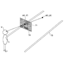
図6は、輝度L_Pと背景輝度L_Bについて説明する図である。図6において、71は虚像の表示可能領域、74は非重畳虚像、75は道路上の白線を示している。[Derivation of conditions for postcard recognition]
FIG. 6 is a diagram illustrating brightness L_P and background brightness L_B. In FIG. 6, 71 is a displayable area of a virtual image, 74 is a non-superimposed virtual image, and 75 is a white line on the road.
図6に示すように、視認者Vから見た表示可能領域71の非画像描画領域内の所定位置Aの輝度をL_Pとし、視認者Vから視た所定位置Aの背後となる背景Bの輝度を背景輝度L_Bとする。所定位置Aの輝度L_Pは、スクリーン104に描画される画像の輝度を変化させることで変化させることができる。
As shown in FIG. 6, the brightness of the predetermined position A in the non-image drawing area of the
所定位置Aの輝度L_P及び背景輝度L_Bは、例えば、図7に示す方法により求めることができる。まず、視認者Vの視点位置(左右の目の中間点)を基準位置とし、2次元輝度計を基準位置に配置する。そして、図7の矢印上側のように、非重畳虚像74(70km/h)を表示しているときの所定位置Aの輝度を2次元輝度計で測定する。この時、非画像描画領域の所定位置Aの輝度L_P+背景輝度L_Bが測定される。 The brightness L_P and the background brightness L_B at the predetermined position A can be obtained by, for example, the method shown in FIG. First, the viewpoint position of the viewer V (the midpoint between the left and right eyes) is set as a reference position, and the two-dimensional luminance meter is placed at the reference position. Then, as shown on the upper side of the arrow in FIG. 7, the brightness of the predetermined position A when the non-superimposed virtual image 74 (70 km / h) is displayed is measured by a two-dimensional luminance meter. At this time, the brightness L_P + background brightness L_B at a predetermined position A in the non-image drawing area is measured.
次に、図7の矢印下側のように、非重畳虚像74(70km/h)を表示していないときの所定位置Aの輝度を2次元輝度計で測定する。この時、背景輝度L_Bのみが測定される。以上2回の測定により、所定位置Aの輝度L_Pと背景輝度L_Bを求めることができる。 Next, as shown on the lower side of the arrow in FIG. 7, the brightness at the predetermined position A when the non-superimposed virtual image 74 (70 km / h) is not displayed is measured with a two-dimensional luminance meter. At this time, only the background brightness L_B is measured. By the above two measurements, the brightness L_P and the background brightness L_B at the predetermined position A can be obtained.
表示可能領域71の所定位置Aを非画像描画領域内で順次移動させて同様の測定を繰り返すことにより、非画像描画領域内の各々の位置にける輝度L_Pと背景輝度L_Bを求めることができる。
By sequentially moving the predetermined position A of the
以上を踏まえて、ポストカードが認識される輝度について精査した。具体的には、スクリーン104に描画される画像の輝度を変化させることで所定位置Aの輝度L_Pを変化させ、ポストカードが視認され始める輝度L_Pの値を2次元輝度計を用いて図7に示した方法で測定した。
Based on the above, we scrutinized the brightness at which postcards are recognized. Specifically, the brightness L_P of the predetermined position A is changed by changing the brightness of the image drawn on the
測定では、所定位置Aの輝度L_Pの背景輝度L_Bに対するコントラストを、L_B/L_Pと定義した。又、背景輝度L_Bは、実験環境が構築可能な3種類を条件とした。この3種類は、それぞれ低い方から夜間の路面輝度、トンネル照明下の路面輝度、曇りの昼間の路面輝度を想定している。 In the measurement, the contrast of the brightness L_P at the predetermined position A with respect to the background brightness L_B was defined as L_B / L_P. In addition, the background brightness L_B was conditioned on three types in which an experimental environment could be constructed. These three types assume road surface brightness at night, road surface brightness under tunnel lighting, and cloudy daytime road surface brightness from the lowest to the lowest.
それぞれの背景輝度L_Bに対して所定位置Aの輝度L_Pを変化させ、ポストカードが認識されなくなるコントラストL_B/L_Pを求めた。なお、所定位置Aの輝度L_P、及び背景輝度L_Bは、図7を参照して説明した方法により求めた。結果を表1に示す。 The brightness L_P at the predetermined position A was changed for each background brightness L_B, and the contrast L_B / L_P at which the postcard was not recognized was obtained. The brightness L_P and the background brightness L_B at the predetermined position A were obtained by the method described with reference to FIG. 7. The results are shown in Table 1.

表1に示すように、ポストカードが視認できる輝度L_Pは背景輝度L_Bによって異なり、例えば夜間の路面相当の背景輝度L_Bでは、コントラストL_B/L_Pが15以上であればポストカードを認識できないことがわかった。又、結果ではL_Bが46.2[cd/cm2]の場合と213[cd/cm2]の場合、でコントラストL_B/L_Pが近い値になっている。
As shown in Table 1, the brightness L_P that can be visually recognized by the postcard differs depending on the background brightness L_B. For example, it was found that the postcard cannot be recognized if the contrast L_B / L_P is 15 or more at the background brightness L_B equivalent to the road surface at night. It was. In addition, as a result, the contrasts L_B / L_P are close to each other when L_B is 46.2 [cd / cm 2 ] and when it is 213 [cd / cm 2 ].
ところで、一般に輝度差弁別閾(人間が輝度の差を認識できる閾値)は環境の明るさによって変動するものの、閾値の輝度/背景輝度が1/100〜1/1000程度であると言われている。 By the way, it is generally said that the brightness difference discrimination threshold (threshold that humans can recognize the difference in brightness) varies depending on the brightness of the environment, but the brightness / background brightness of the threshold is about 1/100 to 1/1000. ..
表1の結果より、背景輝度L_Bがある程度の明るさ(本実験では46.2[cd/cm2])以上であれば、ポストカードが視認できるコントラストは一定であると考えられる。表1の結果に上記の輝度差弁別閾を合わせて考えると、コントラストL_B/L_Pが100以上であれば、背景輝度L_Bによらずポストカードが視認できないと考えられる。From the results in Table 1, if the background brightness L_B is a certain brightness (46.2 [cd / cm 2 ] in this experiment) or more, it is considered that the contrast that the postcard can see is constant. Considering the above-mentioned luminance difference discrimination threshold together with the results in Table 1, if the contrast L_B / L_P is 100 or more, it is considered that the postcard cannot be visually recognized regardless of the background luminance L_B.
以上より、輝度L_P及び背景輝度L_Bにかかわらず、コントラストL_B/L_Pが、概ね100以上の場合に、ポストカードを認識できないことがわかった。つまり、情報表示装置1において、実質的にポストカードが認識できない(ポストカードが実質でない)輝度L_Pの値を設定できることがわかった。但し、表1からわかるように、条件によっては、必ずしもコントラストL_B/L_Pを100以上としなくてもよい。
From the above, it was found that the postcard cannot be recognized when the contrast L_B / L_P is approximately 100 or more regardless of the brightness L_P and the background brightness L_B. That is, it was found that the
情報表示装置1では、表示する虚像の輝度を大きくすると輝度L_Pも大きくなり、表示する虚像の輝度を小さくすると輝度L_Pも小さくなる。従って、情報表示装置1のデータ調整部8210において、コントラストL_B/L_Pが所定値以上となるように、表示する虚像の輝度を調整することにより、常にポストカードを認識できない状態を実現できる。ここで、所定値は100であることが好ましい。又、データ調整以外に光学的な設計において、使用時にこの所定値を満たすよう情報表示装置1を設計しても良い。
In the
ところで、パネル方式では、コントラストL_B/L_Pを100以上にすることは困難であるが、レーザ走査方式では、コントラストL_B/L_Pを1000〜10000程度にすることも容易である。よって、ポストカードを認識できない状態を実現するためには、レーザ走査方式を採用することが好ましい。 By the way, in the panel method, it is difficult to set the contrast L_B / L_P to 100 or more, but in the laser scanning method, it is easy to set the contrast L_B / L_P to about 1000 to 10000. Therefore, in order to realize a state in which the postcard cannot be recognized, it is preferable to adopt a laser scanning method.
又、レーザ走査方式を採用していても、表示している虚像の輝度が高い場合、その虚像の大きさによってポストカード部の輝度も向上する場合がある。この表示虚像の大きさとポストカード部分の輝度に関する測定実験を行った。具体的には、背景輝度L_Bが10000[cd/m2]の場合に、表示が十分に見えるように、虚像を発光させ、その状態で、虚像の大きさ(発光部の面積)を変えながら、ポストカード部の輝度L_Pを測定した。その測定の結果、図8に示すように、表示可能領域全体の面積に対する発光部の面積の比率(面積率)が45%を下回れば、コントラストL_B/L_Pが100以上となることがわかった。Further, even if the laser scanning method is adopted, if the brightness of the displayed virtual image is high, the brightness of the postcard portion may also be improved depending on the size of the virtual image. A measurement experiment was conducted on the size of this display virtual image and the brightness of the postcard part. Specifically, when the background brightness L_B is 10000 [cd / m 2 ], a virtual image is emitted so that the display can be sufficiently seen, and in that state, the size of the virtual image (area of the light emitting portion) is changed. , The brightness L_P of the postcard part was measured. As a result of the measurement, as shown in FIG. 8, it was found that the contrast L_B / L_P is 100 or more when the ratio (area ratio) of the area of the light emitting portion to the area of the entire displayable area is less than 45%.
すなわち、虚像を表示する際に、表示可能領域全体の面積に対する、同時に表示する虚像の面積の合計が、所定の面積率以下(例えば、45%以下程度)であることが好ましい。このようにすることで、表示する虚像の輝度の上限値をある程度高くしても、コントラストL_B/L_Pを100以上とすることができる。 That is, when displaying a virtual image, it is preferable that the total area of the virtual images displayed at the same time with respect to the total area of the displayable area is not more than a predetermined area ratio (for example, about 45% or less). By doing so, the contrast L_B / L_P can be set to 100 or more even if the upper limit of the brightness of the displayed virtual image is raised to some extent.
又、情報表示装置1は、視認者が車両等の運転者であることが多いため、視認者の視界を妨げないようにすることが好ましい。この点からも、表示可能領域全体を発光させずに、同時に表示する(同時に発光させる)虚像の面積の合計を、表示可能領域全体の面積に対して所定の面積率以下とすることが好ましい。
Further, in the
[比較例と実施例]
ここでは、比較例と実施例を示すことにより、3次元的な表示とポストカードについて、図面を参照しながら改めて説明する。[Comparative Examples and Examples]
Here, the three-dimensional display and the postcard will be described again with reference to the drawings by showing comparative examples and examples.
〈比較例〉
図9(比較例)は、パネル方式のHUDを用いて前方車両にマーキングを行った様子を示す模式図である。パネル方式のHUDは、虚像を描画可能な表示可能領域71内の任意の場所に虚像を描画可能であり、図9中では、前方車両72の下に追従して見えるように幾何的な形状を調整し重畳虚像73(所定形状の図形)を表示している。同時に、背景と重畳させずに、2次元的に情報表示を行った非重畳虚像74(45km/h)を表示している。なお、75は道路上の白線を示している。<Comparison example>
FIG. 9 (comparative example) is a schematic view showing a state in which the vehicle in front is marked using the panel-type HUD. The panel-type HUD can draw a virtual image anywhere in the
パネル方式のHUDでは、光源部の光を完全に遮光できないため、表示可能領域71内において、重畳虚像73及び非重畳虚像74が表示されている領域以外の領域(非画像描画領域)も、僅かに光ってしまい、ポストカードが認識される。なお、図9では、非画像描画領域(ポストカード領域)をグレーの塗りつぶしで表現している。
Since the panel-type HUD cannot completely block the light from the light source, the
ポストカードが認識されることで、視認者はHUDの表示可能領域71を視認できてしまう。重畳虚像73は、幾何的な大きさを調整することで、投射距離よりも遠い、前方車両72と同一の位置に存在するように錯覚させようとしている。しかし、ポストカードにより視認者にHUDの表示可能領域71が視認されると、視認者は重畳虚像73と非重畳虚像74とが同一平面上に存在していることを認識してしまい、重畳表現の錯覚が困難となる。
By recognizing the postcard, the viewer can visually recognize the
〈実施例〉
図10(実施例)は、レーザ走査方式のHUDを用いて前方車両にマーキングを行った様子を示す模式図である。レーザ走査方式のHUDもパネル方式のHUDと同様に、重畳虚像73(所定形状の図形)及び非重畳虚像74(45km/h)を表示している。しかし、レーザ走査方式を用いると、表示可能領域71においてポストカードを認識できないようにすることができる。なお、破線で示す四角枠は、便宜上、表示可能領域71の位置を表示したものであって、実際には枠は存在しない(実際には枠は視認できない)。<Example>
FIG. 10 (Example) is a schematic view showing a state in which a vehicle in front is marked using a laser scanning HUD. Similar to the panel type HUD, the laser scanning type HUD also displays the superimposed virtual image 73 (figure of a predetermined shape) and the non-superimposed virtual image 74 (45 km / h). However, if the laser scanning method is used, the postcard cannot be recognized in the
ポストカードが認識できないと、重畳虚像73と非重畳虚像74とは視認者に独立して知覚される。重畳虚像73は、図9の場合と同様に前方車両に追従して見えるように幾何的に調整して表示しており、更にポストカードが認識できないことで、重畳虚像73と非重畳虚像74とは、それぞれ空間中に繋がりなく視認される。そのため、視認者には、重畳したい前方車両72と同様の距離に重畳虚像73が存在していると錯覚して認識される。
If the postcard cannot be recognized, the superimposed
ポストカードは、前述のとおり、コントラストL_B/L_Pが、所定値(概ね100)より小さくなると知覚される。コントラストL_B/L_Pを所定値以上とするためには、例えば、情報表示装置1の情報入力部800が情報取得部5から背景輝度L_Bに関する情報を受信し、情報表示装置1のデータ調整部8210が重畳虚像73と非重畳虚像74の輝度を調整すればよい。
As described above, the postcard is perceived as having a contrast L_B / L_P smaller than a predetermined value (approximately 100). In order to set the contrast L_B / L_P to a predetermined value or more, for example, the
なお、以上の例では、表示可能領域71内に重畳虚像73及び非重畳虚像74を表示している。しかし、重畳虚像73は表示せずに、非重畳虚像74の表示のみを行った場合においても、ポストカードが認識されないことにより、視認者の視認性を妨げないという効果を奏する。
In the above example, the superposed
ところで、情報入力部800が情報取得部5から受信する情報に基づいて、データ調整部8210が環境の明るさに合わせて表示情報(重畳虚像73や非重畳虚像74)の輝度を調整することができる。例えば、夜間の場合は表示情報の輝度を暗く調整し、視認者に対して眩しい等の不快さを与えないようにすることができる。
By the way, the
虚像の背景となる路面の夜間輝度は1〜10[cd/m2]程度であることが一般的であり、この時、非画像描画領域の輝度が0.01〜0.1[cd/m2]以上になると、ポストカードが認識される。ここで、路面輝度が1[cd/m2]の場合、表示情報の輝度は10[cd/m2]程度が適切であることが、知覚実験より明らかになっている。The nighttime brightness of the road surface that is the background of the virtual image is generally about 1 to 10 [cd / m 2 ], and at this time, the brightness of the non-image drawing area is 0.01 to 0.1 [cd / m 2]. When it becomes 2 ] or more, the postcard is recognized. Here, it has been clarified from the perceptual experiment that when the road surface brightness is 1 [cd / m 2 ], the brightness of the display information is appropriately about 10 [cd / m 2 ].
以上をふまえると、ポストカードが認識されず、かつ適切な明るさの表示情報を表示するには、表示可能領域71内に表示する虚像のうち最も輝度が高い虚像の輝度L_Hと非画像描画領域の輝度L_Pとの関係がL_H:L_P=1000:1を満たすことが好ましいといえる。
Based on the above, in order to display display information with appropriate brightness without recognizing the postcard, the brightness L_H of the virtual image with the highest brightness among the virtual images displayed in the
更に、情報表示装置1では、状況に応じて、通常よりも表示情報の輝度を高くし、視認者に注意喚起を行う場合がある。そのため、ポストカードが認識されずに表示情報を表示でき、かつ注意喚起できる明るさにまで表示情報を制御可能とするためには、L_H>1000×L_Pを満たすことが好ましいといえる。
Further, in the
[物体情報の受信]
情報表示装置1では、視認者の視点位置、虚像位置、視点と虚像との距離、虚像の大きさ、虚像の重畳を行いたい範囲に基づいて、表示する像を決定する。例えば、路面に虚像の重畳を行う場合は、重畳を行いたい位置・距離を任意に決定し、視認者の視点から見て、目的の位置・距離に存在して見えるように幾何変換を行った表示を行うことができる。[Reception of object information]
The
路面が平面であることを仮定して虚像の表示を行う場合は、幾何変換を行うのみで表示が可能であるが、カーブや坂道といった路面形状に対応させる場合や、白線に重ねた表示 を行う場合等は、物体情報の取得が必要となる。物体情報とは、例えば、路面において重畳させる位置の座標(位置情報)である。又、前方車両や歩行者等の対象に重畳を行う場合は、これらの対象の位置情報である。又、これら以外の、物体に関する情報であってもよい。 When displaying a virtual image assuming that the road surface is flat, it is possible to display it only by performing geometric transformation, but when making it correspond to the road surface shape such as a curve or a slope, or displaying it overlaid on a white line. In some cases, it is necessary to acquire object information. The object information is, for example, the coordinates (position information) of the positions to be superimposed on the road surface. Further, when superimposing on an object such as a vehicle in front or a pedestrian, it is the position information of these objects. In addition, information about an object other than these may be used.
情報取得部5として、例えば、レーザレーダを用いることにより、物体情報として位置情報を取得することができる。レーザレーダは、レーザビームを出射し、物体(例えば、先行車両、停車車両、構造物、歩行者等)からの反射光(散乱光)を受光することで、位置情報(物体までの距離や物体の座標)を測定する装置である。 By using, for example, a laser radar as the information acquisition unit 5, position information can be acquired as object information. The laser radar emits a laser beam and receives reflected light (scattered light) from an object (for example, a preceding vehicle, a stopped vehicle, a structure, a pedestrian, etc.) to obtain position information (distance to an object or an object). It is a device that measures (coordinates of).
情報取得部5として、ステレオカメラを用いてもよい。ステレオカメラは、左目用となるカメラ部と、右目用となるカメラ部とを備えており、両カメラ部から得られる視差画像から物体の3次元位置情報を算出することができる。 A stereo camera may be used as the information acquisition unit 5. The stereo camera includes a camera unit for the left eye and a camera unit for the right eye, and can calculate three-dimensional position information of an object from parallax images obtained from both camera units.
情報表示装置1は、情報取得部5からの物体情報(例えば物体の3次元位置情報)を情報入力部800で受信し、受信した物体情報を画像データ生成部820に送る。画像データ生成部820は、物体情報に基づいて、表示情報(虚像)のパラメータ(虚像の結像位置、大きさ、形、色、明るさの少なくとも1つ)を調整する。現実物体と3次元的に整合する表示情報を表示する場合には、虚像のパラメータは、現実物体の位置、形、大きさに応じた遠近感が出るように調整されることが好ましい。
The
なお、情報表示装置1は、例えば、交通情報(例えば、渋滞情報や交通ルール等)や気象情報等の情報を情報入力部800で受信し、受信した情報を、現実物体と3次元的に整合するように虚像として表示してもよい。
The
又、情報表示装置1は、例えば、自車両の位置情報を情報入力部800で受信し、受信した情報を、現実物体と3次元的に整合するように虚像として表示してもよい。自車両の位置情報は、例えばGPSを搭載した装置(例えば、カーナビゲーションシステム)から受信することができる。
Further, the
以上、好ましい実施の形態について詳説したが、上述した実施の形態に制限されることはなく、特許請求の範囲に記載された範囲を逸脱することなく、上述した実施の形態に種々の変形及び置換を加えることができる。 Although the preferred embodiment has been described in detail above, it is not limited to the above-described embodiment, and various modifications and substitutions are made to the above-described embodiment without departing from the scope of claims. Can be added.
本国際出願は2016年2月10日に出願した日本国特許出願2016−024051号に基づく優先権を主張するものであり、日本国特許出願2016−024051号の全内容を本国際出願に援用する。 This international application claims priority based on Japanese patent application 2016-024051 filed on February 10, 2016, and the entire contents of Japanese patent application 2016-024051 are incorporated into this international application. ..
1 情報表示装置
10 光学部
20 電気部
71 表示可能領域
72 前方車両
73 重畳虚像
74 非重畳虚像
101 光源部
102 光偏向器
103 ミラー
104 スクリーン
105 凹面ミラー
201 FPGA
202 CPU
203 ROM
204 RAM
205 I/F
206 バスライン
207 LDドライバ
208 MEMSコントローラ
800 情報入力部
820 画像データ生成部
840 画像描画部
8210 データ調整部
8410 制御部1
202 CPU
203 ROM
204 RAM
205 I / F
206
Claims (11)
前記画像の表示可能領域内で、表示する前記画像以外の領域の輝度L_Pと、表示する前記画像以外の領域の背後となる背景輝度L_Bによって求まる値、L_B/L_Pが100以上であり、
表示する前記画像のうち最も明るい画像の明るさL_Hが、L_H>1000×L_Pを満たし、
前記画像の表示可能領域全体の面積に対する、前記表示可能領域に表示する前記画像の面積が、45%以下となるように、前記表示可能領域に表示する前記画像の大きさを調整することを特徴とする情報表示装置。 A laser scanning type information display device that projects an image onto a transmission / reflection member.
Within the displayable area of the image, the value L_B / L_P obtained by the brightness L_P of the area other than the image to be displayed and the background brightness L_B behind the area other than the image to be displayed is 100 or more.
The brightness L_H of the brightest image among the images to be displayed satisfies L_H> 1000 × L_P.
The feature is that the size of the image displayed in the displayable area is adjusted so that the area of the image displayed in the displayable area is 45% or less of the total area of the displayable area of the image. Information display device.
前記表示可能領域全体の面積に対する、同時に表示する前記画像の面積の合計が、45%以下となるように、前記表示可能領域に同時に表示する前記画像の大きさを調整することを特徴とする請求項1に記載の情報表示装置。 When displaying a plurality of the images in the displayable area,
A claim characterized in that the size of the images simultaneously displayed in the displayable area is adjusted so that the total area of the images simultaneously displayed with respect to the total area of the displayable area is 45% or less. Item 1. The information display device according to item 1.
前記物体情報に基づいて、前記視認者から見て前記現実物体と3次元的に整合するように前記交通情報を前記表示可能領域内に前記画像として表示することを特徴とする請求項6乃至8の何れか一項に記載の情報表示装置。 The information input unit further receives traffic information related to the moving body, and receives the traffic information.
Claims 6 to 8 are characterized in that the traffic information is displayed as the image in the displayable area based on the object information so as to be three-dimensionally matched with the real object when viewed from the viewer. The information display device according to any one of the above.
前記位置情報に基づいて、前記視認者から見て前記現実物体と3次元的に整合するように前記画像を表示可能領域内に表示することを特徴とする請求項6乃至9の何れか一項に記載の情報表示装置。 The information input unit further receives the position information of the moving body, and receives the position information of the moving body.
Any one of claims 6 to 9 , wherein the image is displayed in a displayable area so as to be three-dimensionally matched with the real object when viewed from the viewer based on the position information. The information display device described in.
Applications Claiming Priority (3)
| Application Number | Priority Date | Filing Date | Title |
|---|---|---|---|
| JP2016024051 | 2016-02-10 | ||
| JP2016024051 | 2016-02-10 | ||
| PCT/JP2017/003448 WO2017138409A1 (en) | 2016-02-10 | 2017-01-31 | Information display device |
Publications (2)
| Publication Number | Publication Date |
|---|---|
| JPWO2017138409A1 JPWO2017138409A1 (en) | 2019-01-17 |
| JP6780663B2 true JP6780663B2 (en) | 2020-11-04 |
Family
ID=59563843
Family Applications (1)
| Application Number | Title | Priority Date | Filing Date |
|---|---|---|---|
| JP2017566596A Active JP6780663B2 (en) | 2016-02-10 | 2017-01-31 | Information display device |
Country Status (6)
| Country | Link |
|---|---|
| US (1) | US20180339591A1 (en) |
| EP (1) | EP3415971A4 (en) |
| JP (1) | JP6780663B2 (en) |
| KR (1) | KR102124894B1 (en) |
| CN (1) | CN108700744B (en) |
| WO (1) | WO2017138409A1 (en) |
Families Citing this family (15)
| Publication number | Priority date | Publication date | Assignee | Title |
|---|---|---|---|---|
| US10432891B2 (en) * | 2016-06-10 | 2019-10-01 | Magna Electronics Inc. | Vehicle head-up display system |
| US10917619B2 (en) * | 2016-06-20 | 2021-02-09 | Kyocera Corporation | Display apparatus, display system, moveable body, and display method |
| CN108196366B (en) | 2018-01-03 | 2020-07-31 | 京东方科技集团股份有限公司 | Method and device for adjusting display brightness |
| JP2019174519A (en) * | 2018-03-27 | 2019-10-10 | 株式会社リコー | Display unit, display system, moving body, display intensity control method, and program |
| JP7344635B2 (en) * | 2018-09-05 | 2023-09-14 | マクセル株式会社 | heads up display device |
| JP7125713B2 (en) * | 2018-12-27 | 2022-08-25 | スズキ株式会社 | Automotive information display device and information display method |
| JP2020112698A (en) | 2019-01-11 | 2020-07-27 | 株式会社リコー | Display control device, display unit, display system, movable body, program, and image creation method |
| JP2020111202A (en) | 2019-01-11 | 2020-07-27 | 株式会社リコー | Display control device, display device, display system, movable body, program, and image formation method |
| CN109795414A (en) * | 2019-01-25 | 2019-05-24 | 苏州车萝卜汽车电子科技有限公司 | For the image information processing method and device of augmented reality head-up display device, equipment |
| WO2020189258A1 (en) * | 2019-03-19 | 2020-09-24 | コニカミノルタ株式会社 | Display device, head-up display device, and head-mounted display device |
| JP7222285B2 (en) | 2019-03-20 | 2023-02-15 | 株式会社リコー | DISPLAY CONTROL DEVICE, DISPLAY DEVICE, DISPLAY SYSTEM, MOBILE OBJECT, PROGRAM, IMAGE GENERATION METHOD |
| JP7435601B2 (en) * | 2019-05-07 | 2024-02-21 | Agc株式会社 | Display system, display method and transparent display body |
| JP7351478B2 (en) | 2019-07-26 | 2023-09-27 | 株式会社小松製作所 | Display system, remote control system, and display method |
| CN111107332A (en) * | 2019-12-30 | 2020-05-05 | 华人运通(上海)云计算科技有限公司 | HUD projection image display method and device |
| JP2021187420A (en) * | 2020-06-05 | 2021-12-13 | 株式会社小糸製作所 | Display device for vehicle and display method |
Family Cites Families (19)
| Publication number | Priority date | Publication date | Assignee | Title |
|---|---|---|---|---|
| JPH0650953U (en) * | 1992-12-25 | 1994-07-12 | いすゞ自動車株式会社 | Vehicle display |
| US20040244504A1 (en) | 2003-06-04 | 2004-12-09 | Jing Yuan | Apparatus and method of belt dynamic tension measurement |
| JP4476719B2 (en) | 2004-07-02 | 2010-06-09 | よこはまティーエルオー株式会社 | Navigation system |
| US8564502B2 (en) * | 2009-04-02 | 2013-10-22 | GM Global Technology Operations LLC | Distortion and perspective correction of vector projection display |
| KR20100122540A (en) * | 2009-05-13 | 2010-11-23 | 브이앤아이 주식회사 | Apparatus for displaying information in hud system of automotive vehicles |
| JP2012108397A (en) * | 2010-11-19 | 2012-06-07 | Nippon Seiki Co Ltd | Display device |
| JP2014010409A (en) * | 2012-07-02 | 2014-01-20 | Ricoh Co Ltd | Projection display device |
| JP6074964B2 (en) * | 2012-09-17 | 2017-02-08 | 日本精機株式会社 | Vehicle display device |
| JP2014197052A (en) * | 2013-03-29 | 2014-10-16 | 船井電機株式会社 | Projector device and head-up display device |
| US9104038B2 (en) * | 2013-04-25 | 2015-08-11 | Microvision, Inc. | Multiple laser drive method, apparatus and system |
| KR20150087619A (en) * | 2014-01-22 | 2015-07-30 | 한국전자통신연구원 | Apparatus and method for guiding lane change based on augmented reality |
| JP6596668B2 (en) * | 2014-03-27 | 2019-10-30 | パナソニックIpマネジメント株式会社 | Virtual image display device, head-up display system, and vehicle |
| DE102014212186A1 (en) * | 2014-06-25 | 2015-12-31 | Robert Bosch Gmbh | A visual field display device for displaying an image for an occupant of a vehicle |
| JP2016025394A (en) * | 2014-07-16 | 2016-02-08 | 株式会社デンソー | Display device for vehicle |
| JP6448242B2 (en) | 2014-07-18 | 2019-01-09 | 株式会社ミツトヨ | Method for correcting measurement error of shape measuring apparatus and shape measuring apparatus |
| JP6318038B2 (en) * | 2014-07-29 | 2018-04-25 | 株式会社 オルタステクノロジー | Head-up display device |
| JP2017021546A (en) * | 2015-07-10 | 2017-01-26 | 田山 修一 | Image displaying system, and method, for on-vehicle use |
| JP6703747B2 (en) * | 2015-09-18 | 2020-06-03 | 株式会社リコー | Information display device, information providing system, mobile device, information display method and program |
| JP6834537B2 (en) * | 2017-01-30 | 2021-02-24 | 株式会社リコー | Display device, mobile device, manufacturing method and display method of display device. |
-
2017
- 2017-01-31 CN CN201780009790.1A patent/CN108700744B/en active Active
- 2017-01-31 KR KR1020187022526A patent/KR102124894B1/en active IP Right Grant
- 2017-01-31 JP JP2017566596A patent/JP6780663B2/en active Active
- 2017-01-31 EP EP17750133.5A patent/EP3415971A4/en active Pending
- 2017-01-31 WO PCT/JP2017/003448 patent/WO2017138409A1/en active Application Filing
-
2018
- 2018-08-06 US US16/055,318 patent/US20180339591A1/en not_active Abandoned
Also Published As
| Publication number | Publication date |
|---|---|
| CN108700744A (en) | 2018-10-23 |
| EP3415971A1 (en) | 2018-12-19 |
| KR102124894B1 (en) | 2020-06-19 |
| US20180339591A1 (en) | 2018-11-29 |
| KR20180103947A (en) | 2018-09-19 |
| EP3415971A4 (en) | 2019-03-20 |
| WO2017138409A1 (en) | 2017-08-17 |
| CN108700744B (en) | 2021-02-26 |
| JPWO2017138409A1 (en) | 2019-01-17 |
Similar Documents
| Publication | Publication Date | Title |
|---|---|---|
| JP6780663B2 (en) | Information display device | |
| JP6834537B2 (en) | Display device, mobile device, manufacturing method and display method of display device. | |
| US10679496B2 (en) | Information providing apparatus | |
| US10621776B2 (en) | Information display apparatus that changes a virtual image differently from a degree of the change depth | |
| US10551619B2 (en) | Information processing system and information display apparatus | |
| US10549638B2 (en) | Information display apparatus, information provision system, moving object device, information display method, and recording medium | |
| JP6806097B2 (en) | Image display device and image display method | |
| JP2017211366A (en) | Mobile body system and information display device | |
| US11320652B2 (en) | Display device, object apparatus and display method | |
| CN111727399A (en) | Display system, mobile object, and design method |
Legal Events
| Date | Code | Title | Description |
|---|---|---|---|
| A524 | Written submission of copy of amendment under article 19 pct |
Free format text: JAPANESE INTERMEDIATE CODE: A527 Effective date: 20180803 |
|
| A621 | Written request for application examination |
Free format text: JAPANESE INTERMEDIATE CODE: A621 Effective date: 20180803 |
|
| A131 | Notification of reasons for refusal |
Free format text: JAPANESE INTERMEDIATE CODE: A131 Effective date: 20190723 |
|
| A521 | Request for written amendment filed |
Free format text: JAPANESE INTERMEDIATE CODE: A523 Effective date: 20190920 |
|
| A131 | Notification of reasons for refusal |
Free format text: JAPANESE INTERMEDIATE CODE: A131 Effective date: 20200303 |
|
| A521 | Request for written amendment filed |
Free format text: JAPANESE INTERMEDIATE CODE: A523 Effective date: 20200428 |
|
| TRDD | Decision of grant or rejection written | ||
| A01 | Written decision to grant a patent or to grant a registration (utility model) |
Free format text: JAPANESE INTERMEDIATE CODE: A01 Effective date: 20200915 |
|
| A61 | First payment of annual fees (during grant procedure) |
Free format text: JAPANESE INTERMEDIATE CODE: A61 Effective date: 20200928 |
|
| R151 | Written notification of patent or utility model registration |
Ref document number: 6780663 Country of ref document: JP Free format text: JAPANESE INTERMEDIATE CODE: R151 |