JP6740066B2 - Substrate cleaning apparatus, substrate processing apparatus and substrate cleaning method - Google Patents
Substrate cleaning apparatus, substrate processing apparatus and substrate cleaning method Download PDFInfo
- Publication number
- JP6740066B2 JP6740066B2 JP2016178818A JP2016178818A JP6740066B2 JP 6740066 B2 JP6740066 B2 JP 6740066B2 JP 2016178818 A JP2016178818 A JP 2016178818A JP 2016178818 A JP2016178818 A JP 2016178818A JP 6740066 B2 JP6740066 B2 JP 6740066B2
- Authority
- JP
- Japan
- Prior art keywords
- substrate
- cleaning
- cleaning tool
- center
- outer peripheral
- Prior art date
- Legal status (The legal status is an assumption and is not a legal conclusion. Google has not performed a legal analysis and makes no representation as to the accuracy of the status listed.)
- Active
Links
- 239000000758 substrate Substances 0.000 title claims description 966
- 238000004140 cleaning Methods 0.000 title claims description 745
- 238000000034 method Methods 0.000 title description 43
- 238000005498 polishing Methods 0.000 claims description 227
- 230000002093 peripheral effect Effects 0.000 claims description 206
- 238000000576 coating method Methods 0.000 claims description 83
- 239000011248 coating agent Substances 0.000 claims description 80
- 230000032258 transport Effects 0.000 claims description 63
- 230000033001 locomotion Effects 0.000 claims description 59
- 238000003860 storage Methods 0.000 claims description 17
- 238000011109 contamination Methods 0.000 claims description 12
- 239000007788 liquid Substances 0.000 description 50
- 238000001035 drying Methods 0.000 description 45
- 238000010438 heat treatment Methods 0.000 description 39
- 230000018109 developmental process Effects 0.000 description 25
- 230000008569 process Effects 0.000 description 25
- 230000007246 mechanism Effects 0.000 description 24
- 239000010408 film Substances 0.000 description 22
- 238000001816 cooling Methods 0.000 description 21
- 239000013256 coordination polymer Substances 0.000 description 20
- 239000000356 contaminant Substances 0.000 description 19
- 230000003749 cleanliness Effects 0.000 description 16
- 239000012530 fluid Substances 0.000 description 15
- 239000000243 solution Substances 0.000 description 8
- KRHYYFGTRYWZRS-UHFFFAOYSA-N Fluorane Chemical compound F KRHYYFGTRYWZRS-UHFFFAOYSA-N 0.000 description 6
- 102100030373 HSPB1-associated protein 1 Human genes 0.000 description 6
- 101000843045 Homo sapiens HSPB1-associated protein 1 Proteins 0.000 description 6
- 230000008859 change Effects 0.000 description 6
- 230000002452 interceptive effect Effects 0.000 description 6
- 238000005728 strengthening Methods 0.000 description 6
- 239000013039 cover film Substances 0.000 description 5
- 238000010586 diagram Methods 0.000 description 4
- 230000003028 elevating effect Effects 0.000 description 4
- 238000004519 manufacturing process Methods 0.000 description 4
- WGTYBPLFGIVFAS-UHFFFAOYSA-M tetramethylammonium hydroxide Chemical compound [OH-].C[N+](C)(C)C WGTYBPLFGIVFAS-UHFFFAOYSA-M 0.000 description 4
- QTBSBXVTEAMEQO-UHFFFAOYSA-N Acetic acid Chemical compound CC(O)=O QTBSBXVTEAMEQO-UHFFFAOYSA-N 0.000 description 3
- QGZKDVFQNNGYKY-UHFFFAOYSA-N Ammonia Chemical compound N QGZKDVFQNNGYKY-UHFFFAOYSA-N 0.000 description 3
- MUBZPKHOEPUJKR-UHFFFAOYSA-N Oxalic acid Chemical compound OC(=O)C(O)=O MUBZPKHOEPUJKR-UHFFFAOYSA-N 0.000 description 3
- 239000004372 Polyvinyl alcohol Substances 0.000 description 3
- 230000007547 defect Effects 0.000 description 3
- 229920002451 polyvinyl alcohol Polymers 0.000 description 3
- XLYOFNOQVPJJNP-UHFFFAOYSA-N water Substances O XLYOFNOQVPJJNP-UHFFFAOYSA-N 0.000 description 3
- VEXZGXHMUGYJMC-UHFFFAOYSA-N Hydrochloric acid Chemical compound Cl VEXZGXHMUGYJMC-UHFFFAOYSA-N 0.000 description 2
- MHAJPDPJQMAIIY-UHFFFAOYSA-N Hydrogen peroxide Chemical compound OO MHAJPDPJQMAIIY-UHFFFAOYSA-N 0.000 description 2
- NBIIXXVUZAFLBC-UHFFFAOYSA-N Phosphoric acid Chemical compound OP(O)(O)=O NBIIXXVUZAFLBC-UHFFFAOYSA-N 0.000 description 2
- QAOWNCQODCNURD-UHFFFAOYSA-N Sulfuric acid Chemical compound OS(O)(=O)=O QAOWNCQODCNURD-UHFFFAOYSA-N 0.000 description 2
- 239000000428 dust Substances 0.000 description 2
- 230000002708 enhancing effect Effects 0.000 description 2
- 230000006870 function Effects 0.000 description 2
- 238000007654 immersion Methods 0.000 description 2
- 239000000463 material Substances 0.000 description 2
- 230000002265 prevention Effects 0.000 description 2
- 239000004065 semiconductor Substances 0.000 description 2
- 230000007723 transport mechanism Effects 0.000 description 2
- 238000005406 washing Methods 0.000 description 2
- VHUUQVKOLVNVRT-UHFFFAOYSA-N Ammonium hydroxide Chemical compound [NH4+].[OH-] VHUUQVKOLVNVRT-UHFFFAOYSA-N 0.000 description 1
- GRYLNZFGIOXLOG-UHFFFAOYSA-N Nitric acid Chemical compound O[N+]([O-])=O GRYLNZFGIOXLOG-UHFFFAOYSA-N 0.000 description 1
- 239000006061 abrasive grain Substances 0.000 description 1
- 239000012670 alkaline solution Substances 0.000 description 1
- 229910000147 aluminium phosphate Inorganic materials 0.000 description 1
- 229910021529 ammonia Inorganic materials 0.000 description 1
- 239000000969 carrier Substances 0.000 description 1
- 238000001514 detection method Methods 0.000 description 1
- 230000000694 effects Effects 0.000 description 1
- 239000007888 film coating Substances 0.000 description 1
- 238000009501 film coating Methods 0.000 description 1
- 238000000227 grinding Methods 0.000 description 1
- 230000012447 hatching Effects 0.000 description 1
- FFUAGWLWBBFQJT-UHFFFAOYSA-N hexamethyldisilazane Chemical compound C[Si](C)(C)N[Si](C)(C)C FFUAGWLWBBFQJT-UHFFFAOYSA-N 0.000 description 1
- 239000004615 ingredient Substances 0.000 description 1
- 239000004973 liquid crystal related substance Substances 0.000 description 1
- 238000001459 lithography Methods 0.000 description 1
- 239000011259 mixed solution Substances 0.000 description 1
- 229910017604 nitric acid Inorganic materials 0.000 description 1
- 230000003287 optical effect Effects 0.000 description 1
- 235000006408 oxalic acid Nutrition 0.000 description 1
- 230000002787 reinforcement Effects 0.000 description 1
- 239000012744 reinforcing agent Substances 0.000 description 1
- 238000001179 sorption measurement Methods 0.000 description 1
- 239000000126 substance Substances 0.000 description 1
Images


Classifications
-
- B—PERFORMING OPERATIONS; TRANSPORTING
- B24—GRINDING; POLISHING
- B24B—MACHINES, DEVICES, OR PROCESSES FOR GRINDING OR POLISHING; DRESSING OR CONDITIONING OF ABRADING SURFACES; FEEDING OF GRINDING, POLISHING, OR LAPPING AGENTS
- B24B29/00—Machines or devices for polishing surfaces on work by means of tools made of soft or flexible material with or without the application of solid or liquid polishing agents
- B24B29/02—Machines or devices for polishing surfaces on work by means of tools made of soft or flexible material with or without the application of solid or liquid polishing agents designed for particular workpieces
-
- H—ELECTRICITY
- H01—ELECTRIC ELEMENTS
- H01L—SEMICONDUCTOR DEVICES NOT COVERED BY CLASS H10
- H01L21/00—Processes or apparatus adapted for the manufacture or treatment of semiconductor or solid state devices or of parts thereof
- H01L21/67—Apparatus specially adapted for handling semiconductor or electric solid state devices during manufacture or treatment thereof; Apparatus specially adapted for handling wafers during manufacture or treatment of semiconductor or electric solid state devices or components ; Apparatus not specifically provided for elsewhere
- H01L21/67005—Apparatus not specifically provided for elsewhere
- H01L21/67011—Apparatus for manufacture or treatment
- H01L21/67017—Apparatus for fluid treatment
- H01L21/67028—Apparatus for fluid treatment for cleaning followed by drying, rinsing, stripping, blasting or the like
- H01L21/6704—Apparatus for fluid treatment for cleaning followed by drying, rinsing, stripping, blasting or the like for wet cleaning or washing
- H01L21/67046—Apparatus for fluid treatment for cleaning followed by drying, rinsing, stripping, blasting or the like for wet cleaning or washing using mainly scrubbing means, e.g. brushes
-
- B—PERFORMING OPERATIONS; TRANSPORTING
- B08—CLEANING
- B08B—CLEANING IN GENERAL; PREVENTION OF FOULING IN GENERAL
- B08B1/00—Cleaning by methods involving the use of tools
- B08B1/10—Cleaning by methods involving the use of tools characterised by the type of cleaning tool
- B08B1/12—Brushes
-
- B—PERFORMING OPERATIONS; TRANSPORTING
- B08—CLEANING
- B08B—CLEANING IN GENERAL; PREVENTION OF FOULING IN GENERAL
- B08B1/00—Cleaning by methods involving the use of tools
- B08B1/20—Cleaning of moving articles, e.g. of moving webs or of objects on a conveyor
-
- B—PERFORMING OPERATIONS; TRANSPORTING
- B08—CLEANING
- B08B—CLEANING IN GENERAL; PREVENTION OF FOULING IN GENERAL
- B08B11/00—Cleaning flexible or delicate articles by methods or apparatus specially adapted thereto
- B08B11/02—Devices for holding articles during cleaning
-
- B—PERFORMING OPERATIONS; TRANSPORTING
- B08—CLEANING
- B08B—CLEANING IN GENERAL; PREVENTION OF FOULING IN GENERAL
- B08B3/00—Cleaning by methods involving the use or presence of liquid or steam
- B08B3/02—Cleaning by the force of jets or sprays
- B08B3/022—Cleaning travelling work
-
- B—PERFORMING OPERATIONS; TRANSPORTING
- B08—CLEANING
- B08B—CLEANING IN GENERAL; PREVENTION OF FOULING IN GENERAL
- B08B7/00—Cleaning by methods not provided for in a single other subclass or a single group in this subclass
- B08B7/04—Cleaning by methods not provided for in a single other subclass or a single group in this subclass by a combination of operations
-
- H—ELECTRICITY
- H01—ELECTRIC ELEMENTS
- H01L—SEMICONDUCTOR DEVICES NOT COVERED BY CLASS H10
- H01L21/00—Processes or apparatus adapted for the manufacture or treatment of semiconductor or solid state devices or of parts thereof
- H01L21/02—Manufacture or treatment of semiconductor devices or of parts thereof
- H01L21/02041—Cleaning
- H01L21/02057—Cleaning during device manufacture
-
- H—ELECTRICITY
- H01—ELECTRIC ELEMENTS
- H01L—SEMICONDUCTOR DEVICES NOT COVERED BY CLASS H10
- H01L21/00—Processes or apparatus adapted for the manufacture or treatment of semiconductor or solid state devices or of parts thereof
- H01L21/02—Manufacture or treatment of semiconductor devices or of parts thereof
- H01L21/02041—Cleaning
- H01L21/02096—Cleaning only mechanical cleaning
Landscapes
- Engineering & Computer Science (AREA)
- Physics & Mathematics (AREA)
- Condensed Matter Physics & Semiconductors (AREA)
- General Physics & Mathematics (AREA)
- Manufacturing & Machinery (AREA)
- Computer Hardware Design (AREA)
- Microelectronics & Electronic Packaging (AREA)
- Power Engineering (AREA)
- Mechanical Engineering (AREA)
- Cleaning Or Drying Semiconductors (AREA)
- Exposure Of Semiconductors, Excluding Electron Or Ion Beam Exposure (AREA)
Description
本発明は、基板の洗浄を行う基板洗浄装置、基板処理装置および基板洗浄方法に関する。 The present invention relates to a substrate cleaning apparatus, a substrate processing apparatus and a substrate cleaning method for cleaning a substrate.
半導体デバイス等の製造におけるリソグラフィ工程では、基板上にレジスト液等の塗布液が供給されることにより塗布膜が形成される。塗布膜が露光された後、現像されることにより、塗布膜に所定のパターンが形成される。塗布膜が露光される前の基板には、洗浄処理が行われる(例えば、特許文献1参照)。 In a lithography process in manufacturing a semiconductor device or the like, a coating film is formed by supplying a coating liquid such as a resist liquid onto a substrate. The coating film is exposed and then developed to form a predetermined pattern on the coating film. A cleaning process is performed on the substrate before the coating film is exposed (see, for example, Patent Document 1).
特許文献1には、洗浄/乾燥処理ユニットを有する基板処理装置が記載されている。洗浄/乾燥処理ユニットにおいては、スピンチャックにより基板が水平に保持された状態で回転される。この状態で、基板の表面に洗浄液が供給されることにより、基板の表面に付着する塵埃等が洗い流される。また、基板の裏面の全体および外周端部が洗浄液および洗浄ブラシで洗浄されることにより、基板の裏面の全体および外周端部に付着する汚染物が取り除かれる。
基板に形成されるパターンをより微細化するために基板の裏面のより高い清浄度が求められる。スループットの低下を抑制しつつ基板の裏面の清浄度を向上させるために、複数の洗浄ブラシを同時に使用して基板の裏面を洗浄することが考えられる。 Higher cleanliness of the back surface of the substrate is required to make the pattern formed on the substrate finer. In order to improve the cleanliness of the back surface of the substrate while suppressing the decrease in throughput, it is possible to use a plurality of cleaning brushes at the same time to clean the back surface of the substrate.
複数の洗浄ブラシを用いた基板の洗浄方法の一例として、特許文献2には、2つの洗浄ブラシを基板の回転中心と基板の周縁部との間でそれぞれ往復運動させつつ基板の表面を洗浄することが記載されている。この洗浄方法においては、基板の表面の洗浄が行われる前に、予め使用者により2つの洗浄ブラシについてそれぞれの動作パターンが作成される。
As an example of a method of cleaning a substrate using a plurality of cleaning brushes,
使用者により動作パターンが作成されると、生成された動作パターンに従って2つの洗浄ブラシが動作したと仮定した上で、2つの洗浄ブラシが互いに干渉するか否かが判定される。2つの洗浄ブラシが互いに干渉すると判定された場合には、使用者に動作パターンの再作成が要求される。使用者は、2つの洗浄ブラシが互いに干渉しないと判定されるまで、動作パターンの作成を繰り返す必要がある。このような動作パターンの作成は煩雑である。 When the operation pattern is created by the user, it is determined whether the two cleaning brushes interfere with each other, assuming that the two cleaning brushes operate according to the generated operation pattern. If it is determined that the two cleaning brushes interfere with each other, the user is required to recreate the operation pattern. The user needs to repeat the creation of the motion pattern until it is determined that the two cleaning brushes do not interfere with each other. Creating such an operation pattern is complicated.
動作パターンを用いることなく2つの洗浄ブラシで基板を洗浄するために、一方のブラシで基板を洗浄する間に他方のブラシを基板の外方の位置に待機させ、他方のブラシで基板を洗浄する間に一方のブラシを基板の外方の位置に待機させる方法が考えられる。しかしながら、この洗浄方法では、基板処理のスループットが低下する。 In order to clean the substrate with the two cleaning brushes without using the operation pattern, the other brush is made to stand by at the position outside the substrate while the other brush is cleaning the substrate while the other brush is cleaning the substrate. A method in which one brush is made to stand by at a position outside the substrate may be considered. However, this cleaning method reduces the throughput of substrate processing.
本発明の目的は、複数の洗浄具の動作について煩雑な設定作業が不要でかつスループットの低下を抑制しつつ基板の清浄度を向上させることが可能な基板洗浄装置、基板処理装置および基板洗浄方法を提供することである。 An object of the present invention is to eliminate the need for complicated setting work for the operation of a plurality of cleaning tools, and to improve the cleanliness of substrates while suppressing a decrease in throughput, a substrate processing apparatus, and a substrate cleaning method. Is to provide.
(1)本発明に係る基板洗浄装置は、基板を保持して回転させる回転保持部と、基板の一面に接触可能に構成された第1および第2の洗浄具と、第1の洗浄具を回転保持部により回転される基板の中心と基板の外周部とを結ぶ第1の経路に沿って移動させる第1の移動部と、第2の洗浄具を回転保持部により回転される基板の中心と基板の外周部とを結ぶ第2の経路に沿って移動させる第2の移動部と、基板の中心から基板の外周部に向かって移動する第1の洗浄具が、第1の経路に沿った第1の洗浄具の軌跡と第2の経路に沿った第2の洗浄具の軌跡とが重複する干渉領域から外れる時点における第1の洗浄具の位置を示す位置情報を予め記憶する記憶部と、第1の洗浄具が基板の中心から基板の外周部に向かって移動するように第1の移動部を制御するとともに、第2の洗浄具が基板の外周部から基板の中心に向かって移動するように第2の移動部を制御する制御部とを備え、制御部は、第1および第2の移動部の制御を行う前に、第1の洗浄具が基板の中心から基板の外周部に向かうときの第1の移動速度と第2の洗浄具が基板の外周部から基板の中心に向かうときの第2の移動速度とを予め比較し、第1の移動速度が第2の移動速度よりも低い場合に、第1の移動部の制御を開始した後、位置情報に基づいて第1の洗浄具が干渉領域から外れたか否かを判定し、第1の洗浄具が干渉領域から外れたと判定した時点で、基板の外周部から基板の中心に向かう第2の洗浄具の移動が開始されるように第2の移動部を制御し、第1の移動速度が第2の移動速度以上である場合に、基板の中心から基板の外周部に向かう第1の洗浄具の移動と、基板の外周部から基板の中心に向かう第2の洗浄具の移動とが同時に開始されるように第1および第2の移動部を制御し、第1の洗浄具が干渉領域から外れたか否かの判定を行わない。 (1) A substrate cleaning apparatus according to the present invention includes a rotation holding unit that holds and rotates a substrate, first and second cleaning tools configured to be in contact with one surface of the substrate, and a first cleaning tool. a first moving unit that moves along a first path connecting the outer periphery and the center of the substrate of the base plate that will be rotated by the rotary holding unit, board that will be rotated by the rotation holding portion of the second cleaner A second moving unit that moves along a second path that connects the center of the substrate to the outer peripheral portion of the substrate, and a first cleaning tool that moves from the center of the substrate toward the outer peripheral portion of the substrate. Position information indicating the position of the first cleaning tool at the time when the trajectory of the first cleaning tool along the path and the trajectory of the second cleaning tool along the second path deviate from the overlapping interference region is stored in advance. The storage unit and the first cleaning unit are controlled so that the first cleaning tool moves from the center of the substrate toward the outer periphery of the substrate , and the second cleaning tool moves from the outer periphery of the substrate to the center of the substrate. A control unit for controlling the second moving unit so as to move toward the first moving unit before the control of the first and second moving units. The first moving speed when moving toward the outer peripheral portion of the substrate and the second moving speed when the second cleaning tool moves from the outer peripheral portion of the substrate toward the center of the substrate are compared in advance, and the first moving speed is the second moving speed. If the moving speed of the first cleaning tool is lower than the moving speed of the first cleaning tool, it is determined whether the first cleaning tool is out of the interference area based on the position information after the control of the first moving unit is started. When it is determined that the second cleaning tool is moved from the outer peripheral portion of the substrate toward the center of the substrate when it is determined that the second moving portion is moved from the outer peripheral portion to the center of the substrate, the first moving speed is set to the second moving speed. When the moving speed is equal to or higher than the moving speed, the movement of the first cleaning tool from the center of the substrate toward the outer peripheral portion of the substrate and the movement of the second cleaning tool from the outer peripheral portion of the substrate toward the center of the substrate are simultaneously started. Thus, the first and second moving parts are controlled, and it is not determined whether or not the first cleaning tool is out of the interference area .
その基板洗浄装置においては、回転される基板の一面に第1の洗浄具が接触されつつ第1の洗浄具が第1の経路に沿って移動し、回転される基板の一面に第2の洗浄具が接触されつつ第2の洗浄具が第2の経路に沿って移動する。それにより、基板が第1および第2の洗浄具により洗浄される。 In the substrate cleaning apparatus, the first cleaning tool moves along the first path while the first cleaning tool contacts one surface of the rotated substrate, and the second cleaning tool moves on the one surface of the rotated substrate. The second cleaning tool moves along the second path while the tools are in contact with each other. Thereby, the substrate is cleaned by the first and second cleaning tools.
第1および第2の移動部の制御が行われる前に、第1の移動速度と第2の移動速度とが予め比較される。第1の移動速度が第2の移動速度よりも低い場合に、第1の洗浄具が基板の中心から基板の外周部に向かって移動されるとともに、第1の洗浄具が干渉領域から外れたか否かが判定される。第1の洗浄具が干渉領域から外れたと判定された時点で基板の外周部から基板の中心に向かう第2の洗浄具の移動が開始される。この場合、第1の洗浄具が干渉領域から外れているので、第1および第2の洗浄具が同時に移動しても第1の洗浄具と第2の洗浄具とは干渉しない。したがって、第1および第2の洗浄具の移動について煩雑な設定作業を要することなく、第1の洗浄具と第2の洗浄具との干渉を防止することができる。 Before the control of the first and second moving units is performed, the first moving speed and the second moving speed are compared in advance. Whether the first cleaning tool is moved from the center of the substrate toward the outer peripheral portion of the substrate when the first moving speed is lower than the second moving speed , and whether the first cleaning tool is out of the interference region It is determined whether or not. When it is determined that the first cleaning tool is out of the interference region, the movement of the second cleaning tool from the outer peripheral portion of the substrate toward the center of the substrate is started. In this case, since the first cleaning tool is out of the interference region, even if the first and second cleaning tools move at the same time, the first cleaning tool and the second cleaning tool do not interfere with each other. Therefore, it is possible to prevent interference between the first cleaning tool and the second cleaning tool without requiring a complicated setting operation for moving the first and second cleaning tools.
また、上記の構成によれば、第1の洗浄具が基板の外周部に到達する前に第2の洗浄具が基板の外周部から基板の中心への移動を開始するので、第1の洗浄具が外周部への移動を開始してから第2の洗浄具が基板の中心に到達するまでの時間を短縮することができる。したがって、第1の洗浄具による基板の洗浄後または洗浄中に、第2の洗浄具による基板の洗浄を迅速に行うことができる。
第1の移動速度が第2の移動速度以上である場合には、第1の洗浄具が基板の中心から基板の外周部に向かう移動と、第2の洗浄具が基板の外周部から基板の中心に向かう移動とを同時に開始しても、第1および第2の洗浄具は互いに干渉しない。そこで、第1の洗浄具の移動と第2の洗浄具の移動とが同時に開始され、第1の洗浄具が干渉領域から外れたか否かの判定が行われない。それにより、基板の外周部から基板の中心に向かう第2の洗浄具の移動をより早い時点で開始させることができる。したがって、基板の中心から基板の外周部への第1の洗浄具の移動が開始された時点からより短時間で第2の洗浄具を基板の中心に移動させることができる。
Further, according to the above configuration, the second cleaning tool starts moving from the outer peripheral portion of the substrate to the center of the substrate before the first cleaning tool reaches the outer peripheral portion of the substrate. The time from when the tool starts to move to the outer peripheral portion until the second cleaning tool reaches the center of the substrate can be shortened. Therefore, the substrate can be quickly cleaned by the second cleaning tool after or during the cleaning of the substrate by the first cleaning tool.
When the first moving speed is equal to or higher than the second moving speed, the first cleaning tool moves from the center of the substrate toward the outer peripheral portion of the substrate, and the second cleaning tool moves from the outer peripheral portion of the substrate to the substrate. Even if the movement toward the center is started at the same time, the first and second cleaning tools do not interfere with each other. Therefore, the movement of the first cleaning tool and the movement of the second cleaning tool are simultaneously started, and it is not determined whether or not the first cleaning tool is out of the interference area. Thereby, the movement of the second cleaning tool from the outer peripheral portion of the substrate toward the center of the substrate can be started at an earlier time. Therefore, the second cleaning tool can be moved to the center of the substrate in a shorter time after the movement of the first cleaning tool from the center of the substrate to the outer peripheral portion of the substrate is started.
これらの結果、第1および第2の洗浄具の移動について干渉を防止するための煩雑な設定作業が不要でかつスループットの低下を抑制しつつ基板の清浄度を向上させることが可能になる。 As a result of these, it is possible to improve the cleanliness of the substrate while suppressing the decrease in throughput without the need for complicated setting work for preventing the interference of the movement of the first and second cleaning tools.
(2)第2の移動速度は、第1の移動速度よりも高くてもよい。 (2) The second moving speed may be higher than the first moving speed.
この場合、第1の洗浄具が干渉領域から外れた時点から短時間で第2の洗浄具を基板の中心に移動させることができる。 In this case, the second cleaning tool can be moved to the center of the substrate in a short time from the time when the first cleaning tool deviates from the interference region.
(3)制御部は、第1の洗浄具が基板の外周部から基板の中心に向かって移動する間に第1の洗浄具が基板の一面から離間し、第1の洗浄具が基板の中心から基板の外周部に向かって移動する間に第1の洗浄具が基板の一面に接触するように第1の移動部を制御し、第2の洗浄具が基板の外周部から基板の中心に向かって移動する間に第2の洗浄具が基板の一面から離間し、第2の洗浄具が基板の中心から基板の外周部に向かって移動する間に第2の洗浄具が基板の一面に接触するように第2の移動部を制御してもよい。 (3) The control unit separates the first cleaning tool from one surface of the substrate while the first cleaning tool moves from the outer peripheral portion of the substrate toward the center of the substrate, and the first cleaning tool moves to the center of the substrate. From the outer periphery of the substrate to the center of the substrate while controlling the first moving part so that the first cleaning tool contacts one surface of the substrate while moving from the outer periphery of the substrate to the center of the substrate. The second cleaning tool separates from one surface of the substrate while moving toward the outer surface of the substrate, and the second cleaning tool moves to one surface of the substrate while moving from the center of the substrate toward the outer peripheral portion of the substrate. The second moving unit may be controlled so as to make contact.
この場合、第1の洗浄具が基板の中心から基板の外周部に向かって移動する間に基板の一面が第1の洗浄具により洗浄される。第1の洗浄具による基板の一面の洗浄時に、第1の洗浄具により除去された汚染物は、遠心力により基板の外周部に向かって流れる。それにより、除去された汚染物が第1の洗浄具よりも基板の中心側に回り込むことが防止される。 In this case, one surface of the substrate is cleaned by the first cleaning tool while the first cleaning tool moves from the center of the substrate toward the outer peripheral portion of the substrate. When the one surface of the substrate is cleaned by the first cleaning tool, the contaminants removed by the first cleaning tool flow toward the outer peripheral portion of the substrate due to the centrifugal force. This prevents the removed contaminants from wrapping around the center of the substrate with respect to the first cleaning tool.
第2の洗浄具が基板の中心から基板の外周部に向かって移動する間に基板の一面が第2の洗浄具により洗浄される。第2の洗浄具による基板の一面の洗浄時に、第2の洗浄具により除去された汚染物は、遠心力により基板の外周部に向かって流れる。それにより、除去された汚染物が第2の洗浄具よりも基板の中心側に回り込むことが防止される。 While the second cleaning tool moves from the center of the substrate toward the outer peripheral portion of the substrate, one surface of the substrate is cleaned by the second cleaning tool. When the one surface of the substrate is cleaned by the second cleaning tool, the contaminants removed by the second cleaning tool flow toward the outer peripheral portion of the substrate due to the centrifugal force. This prevents the removed contaminants from wrapping around the center of the substrate with respect to the second cleaning tool.
これらの結果、第1および第2の洗浄具による洗浄後の基板の清浄度がより向上する。 As a result, the cleanliness of the substrate after being cleaned by the first and second cleaning tools is further improved.
(4)第1の洗浄具が基板の外周部から基板の中心に向かって移動する速度は、第1の洗浄具が基板の中心から基板の外周部に向かって移動する第1の移動速度よりも高く、第2の洗浄具が基板の外周部から基板の中心に向かって移動する第2の移動速度は、第2の洗浄具が基板の中心から基板の外周部に向かって移動する速度よりも高くてもよい。 (4) The speed at which the first cleaning tool moves from the outer peripheral portion of the substrate toward the center of the substrate is greater than the first moving speed at which the first cleaning tool moves from the center of the substrate toward the outer peripheral portion of the substrate. The second moving speed at which the second cleaning tool moves from the outer peripheral portion of the substrate toward the center of the substrate is higher than the speed at which the second cleaning tool moves from the center of the substrate toward the outer peripheral portion of the substrate. May be higher.
この場合、基板の外周部に位置する第1および第2の洗浄具を短時間で基板の中心に移動させることができる。 In this case, the first and second cleaning tools located on the outer peripheral portion of the substrate can be moved to the center of the substrate in a short time.
(5)第1の洗浄具は、研磨具であり、第2の洗浄具は、ブラシであってもよい。 (5) The first cleaning tool may be a polishing tool, and the second cleaning tool may be a brush.
この場合、研磨具による基板の一面の研磨後に、ブラシにより基板の一面が洗浄される。それにより、基板の一面の研磨により発生する汚染物が除去される。したがって、基板の清浄度がさらに向上する。 In this case, after polishing the one surface of the substrate with the polishing tool, the one surface of the substrate is washed with the brush. As a result, contaminants generated by polishing the one surface of the substrate are removed. Therefore, the cleanliness of the substrate is further improved.
(6)本発明に係る基板処理装置は、露光装置に隣接するように配置される基板処理装置であって、基板の上面に感光性膜を塗布する塗布装置と、上記の基板洗浄装置と、塗布装置、基板洗浄装置および露光装置の間で基板を搬送する搬送装置とを備え、基板洗浄装置は、露光装置による基板の露光処理前に基板の一面としての下面の汚染を除去する。 ( 6 ) A substrate processing apparatus according to the present invention is a substrate processing apparatus arranged adjacent to an exposure apparatus, the coating apparatus coating a photosensitive film on the upper surface of a substrate, the substrate cleaning apparatus described above, The substrate cleaning device includes a coating device, a substrate cleaning device, and a transport device that transports the substrate between the exposure devices. The substrate cleaning device removes contamination on the lower surface as one surface of the substrate before the exposure processing of the substrate by the exposure device.
その基板処理装置においては、露光処理前の基板の下面の汚染が上記の基板洗浄装置により除去される。上記の基板洗浄装置によれば、第1および第2の洗浄具の移動について煩雑な設定作業が不要でかつスループットの低下を抑制しつつ基板の清浄度を向上させることが可能である。その結果、基板の製造コストを増大させることなく基板の下面の汚染に起因する基板の処理不良の発生が抑制される。 In the substrate processing apparatus, contamination on the lower surface of the substrate before the exposure processing is removed by the substrate cleaning apparatus. According to the substrate cleaning apparatus described above, it is possible to improve the cleanliness of the substrate without requiring a complicated setting operation for moving the first and second cleaning tools and suppressing a decrease in throughput. As a result, the occurrence of processing defects of the substrate due to contamination of the lower surface of the substrate is suppressed without increasing the manufacturing cost of the substrate.
(7)本発明に係る基板洗浄方法は、基板を保持して回転させるステップと、第1の洗浄具を回転される基板の中心と基板の外周部とを結ぶ第1の経路に沿って基板の中心から基板の外周部に移動させるとともに、第2の洗浄具を回転される基板の中心と基板の外周部とを結ぶ第2の経路に沿って基板の外周部から基板の中心に移動させるステップと、第1および第2の洗浄具を移動させるステップの前に、基板の中心から基板の外周部に向かって移動する第1の洗浄具が、第1の経路に沿った第1の洗浄具の軌跡と第2の経路に沿った第2の洗浄具の軌跡とが重複する干渉領域から外れる時点における第1の洗浄具の位置を示す位置情報を予め記憶するステップと、第1および第2の洗浄具を移動させるステップの前に、第1の洗浄具が基板の中心から基板の外周部に向かうときの第1の移動速度と第2の洗浄具が基板の外周部から基板の中心に向かうときの第2の移動速度とを予め比較するステップとを含み、第1および第2の洗浄具を移動させるステップは、比較するステップにおいて第1の移動速度が第2の移動速度よりも低い場合に、基板の中心から基板の外周部に向かう第1の洗浄具の移動を開始した後、位置情報に基づいて第1の洗浄具が干渉領域から外れたか否かを判定し、第1の洗浄具が干渉領域から外れたと判定した時点で、基板の外周部から基板の中心に向かう第2の洗浄具の移動を開始することと、比較するステップにおいて第1の移動速度が第2の移動速度以上である場合に、基板の中心から基板の外周部に向かう第1の洗浄具の移動と、基板の外周部から基板の中心に向かう第2の洗浄具の移動とを同時に開始し、第1の洗浄具が干渉領域から外れたか否かの判定を行わないこととを含む。 (7) The substrate cleaning method according to the present invention, along a first path connecting the steps of holding and rotating a substrate, an outer peripheral portion and the center of the substrate of the first cleaner based on Ru rotated plate is moved from the center of the substrate to the outer peripheral portion of the substrate, the center of the substrate from the outer periphery of the substrate along a second path connecting the outer periphery and the center of the substrate of the second cleaner based on Ru rotated plate Before the step of moving and the step of moving the first and second cleaning tools , the first cleaning tool that moves from the center of the substrate toward the outer peripheral portion of the substrate has the first cleaning tool along the first path. a step of trajectory of the cleaning tool and the trajectory of the second cleaning tool along a second path for previously storing position information indicating the position of the first cleaner at the time out of the interference region overlapping, first And before the step of moving the second cleaning tool, the first moving speed when the first cleaning tool moves from the center of the substrate to the outer peripheral portion of the substrate and the second cleaning tool moves from the outer peripheral portion of the substrate to the substrate. In advance, the step of moving the first and second cleaning tools includes the step of comparing the second moving speed with the second moving speed when moving toward the center of the first moving speed. If it is lower than, after starting the movement of the first cleaning tool from the center of the substrate to the outer peripheral portion of the substrate, it is determined whether the first cleaning tool is out of the interference region based on the position information, When it is determined that the first cleaning tool is out of the interference region, the movement of the second cleaning tool from the outer peripheral portion of the substrate toward the center of the substrate is started, and the first moving speed is set to the first moving speed in the comparing step. When the moving speed is 2 or more, the movement of the first cleaning tool from the center of the substrate toward the outer peripheral portion of the substrate and the movement of the second cleaning tool from the outer peripheral portion of the substrate toward the center of the substrate are simultaneously started. However, it is not determined whether the first cleaning tool is out of the interference area .
その基板洗浄方法においては、回転される基板の一面に第1の洗浄具が接触されつつ第1の洗浄具が第1の経路に沿って移動し、回転される基板の一面に第2の洗浄具が接触されつつ第2の洗浄具が第2の経路に沿って移動する。それにより、基板が第1および第2の洗浄具により洗浄される。 In the substrate cleaning method, the first cleaning tool moves along the first path while the first cleaning tool is in contact with the one surface of the rotated substrate, and the second cleaning tool is moved on the one surface of the rotated substrate. The second cleaning tool moves along the second path while the tools are in contact with each other. Thereby, the substrate is cleaned by the first and second cleaning tools.
第1および第2の洗浄具の移動が行われる前に、第1の移動速度と第2の移動速度とが予め比較される。第1の移動速度が第2の移動速度よりも低い場合に、第1の洗浄具が基板の中心から基板の外周部に向かって移動されるとともに、第1の洗浄具が干渉領域から外れたか否かが判定される。第1の洗浄具が干渉領域から外れたと判定された時点で基板の外周部から基板の中心に向かう第2の洗浄具の移動が開始される。この場合、第1の洗浄具が干渉領域から外れているので、第1および第2の洗浄具が同時に移動しても第1の洗浄具と第2の洗浄具とは干渉しない。したがって、第1および第2の洗浄具の移動について煩雑な設定作業を要することなく、第1の洗浄具と第2の洗浄具との干渉を防止することができる。 Before the movement of the first and second cleaning tools is performed, the first movement speed and the second movement speed are compared in advance. Whether the first cleaning tool is moved from the center of the substrate toward the outer peripheral portion of the substrate when the first moving speed is lower than the second moving speed , and whether the first cleaning tool is out of the interference region It is determined whether or not. When it is determined that the first cleaning tool is out of the interference region, the movement of the second cleaning tool from the outer peripheral portion of the substrate toward the center of the substrate is started. In this case, since the first cleaning tool is out of the interference region, even if the first and second cleaning tools move at the same time, the first cleaning tool and the second cleaning tool do not interfere with each other. Therefore, it is possible to prevent interference between the first cleaning tool and the second cleaning tool without requiring a complicated setting operation for moving the first and second cleaning tools.
また、上記の構成によれば、第1の洗浄具が基板の外周部に到達する前に第2の洗浄具が基板の外周部から基板の中心への移動を開始するので、第1の洗浄具が外周部への移動を開始してから第2の洗浄具が基板の中心に到達するまでの時間を短縮することができる。したがって、第1の洗浄具による基板の洗浄後または洗浄中に、第2の洗浄具による基板の洗浄を迅速に行うことができる。
第1の移動速度が第2の移動速度以上である場合には、第1の洗浄具が基板の中心から基板の外周部に向かう移動と、第2の洗浄具が基板の外周部から基板の中心に向かう移動とを同時に開始しても、第1および第2の洗浄具は互いに干渉しない。そこで、第1の洗浄具の移動と第2の洗浄具の移動とが同時に開始され、第1の洗浄具が干渉領域から外れたか否かの判定が行われない。それにより、基板の外周部から基板の中心に向かう第2の洗浄具の移動をより早い時点で開始させることができる。したがって、基板の中心から基板の外周部への第1の洗浄具の移動が開始された時点からより短時間で第2の洗浄具を基板の中心に移動させることができる。
Further, according to the above configuration, the second cleaning tool starts moving from the outer peripheral portion of the substrate to the center of the substrate before the first cleaning tool reaches the outer peripheral portion of the substrate. The time from when the tool starts to move to the outer peripheral portion until the second cleaning tool reaches the center of the substrate can be shortened. Therefore, the substrate can be quickly cleaned by the second cleaning tool after or during the cleaning of the substrate by the first cleaning tool.
When the first moving speed is equal to or higher than the second moving speed, the first cleaning tool moves from the center of the substrate toward the outer peripheral portion of the substrate, and the second cleaning tool moves from the outer peripheral portion of the substrate to the substrate. Even if the movement toward the center is started at the same time, the first and second cleaning tools do not interfere with each other. Therefore, the movement of the first cleaning tool and the movement of the second cleaning tool are simultaneously started, and it is not determined whether or not the first cleaning tool is out of the interference area. Thereby, the movement of the second cleaning tool from the outer peripheral portion of the substrate toward the center of the substrate can be started at an earlier time. Therefore, the second cleaning tool can be moved to the center of the substrate in a shorter time after the movement of the first cleaning tool from the center of the substrate to the outer peripheral portion of the substrate is started.
これらの結果、第1および第2の洗浄具の移動について干渉を防止するための煩雑な設定作業が不要でかつスループットの低下を抑制しつつ基板の清浄度を向上させることが可能になる。 As a result of these, it is possible to improve the cleanliness of the substrate while suppressing the decrease in throughput without the need for complicated setting work for preventing the interference of the movement of the first and second cleaning tools.
本発明によれば、複数の洗浄具の動作について煩雑な設定作業が不要でかつスループットの低下を抑制しつつ基板の清浄度を向上させることが可能になる。 According to the present invention, it is possible to improve the cleanliness of a substrate without requiring a complicated setting operation for the operation of a plurality of cleaning tools and suppressing a decrease in throughput.
以下、本発明の一実施の形態に係る基板洗浄装置、基板処理装置および基板洗浄方法について図面を用いて説明する。なお、以下の説明において、基板とは、半導体基板、液晶表示装置用基板、プラズマディスプレイ用基板、光ディスク用基板、磁気ディスク用基板、光磁気ディスク用基板またはフォトマスク用基板等をいう。また、基板の上面とは上方に向けられた基板の面をいい、基板の下面とは下方に向けられた基板の面をいう。 A substrate cleaning apparatus, a substrate processing apparatus and a substrate cleaning method according to an embodiment of the present invention will be described below with reference to the drawings. In the following description, the substrate means a semiconductor substrate, a liquid crystal display device substrate, a plasma display substrate, an optical disk substrate, a magnetic disk substrate, a magneto-optical disk substrate, a photomask substrate, or the like. The upper surface of the substrate means the surface of the substrate facing upward, and the lower surface of the substrate means the surface of the substrate facing downward.
本発明においては、基板の汚染とは、基板が汚染物、吸着痕または接触痕等により汚れている状態をいう。また、本発明においては、基板の洗浄には、研磨具を用いて基板の一面を研磨することにより汚染を除去する洗浄と、ブラシを用いて基板の一面を研磨することなく汚染を除去する洗浄とが含まれる。以下の説明では、研磨具を用いた基板の洗浄を研磨洗浄と呼び、ブラシを用いた基板の洗浄をブラシ洗浄と呼ぶ。 In the present invention, the term "contamination of the substrate" means a state in which the substrate is contaminated with contaminants, adsorption marks, contact marks, or the like. Further, in the present invention, the cleaning of the substrate is performed by polishing the one surface of the substrate with a polishing tool to remove the contamination and by cleaning the substrate with a brush to remove the contamination without polishing the one surface of the substrate. And are included. In the following description, cleaning the substrate using the polishing tool is called polishing cleaning, and cleaning the substrate using the brush is called brush cleaning.
[1]基板洗浄装置
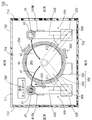
図1は本発明の一実施の形態に係る基板洗浄装置の概略構成を示す模式的平面図である。
[1] Substrate Cleaning Device FIG. 1 is a schematic plan view showing a schematic configuration of a substrate cleaning device according to an embodiment of the present invention.
図1に示すように、基板洗浄装置700は、スピンチャック200、ガード機構300、複数(本例では3つ)の受け渡し機構350、基板研磨部400、基板洗浄部500、筐体710および洗浄コントローラ780を含む。
As shown in FIG. 1 , the
筐体710は、4つの側壁711,712,713,714、天井部(図示せず)および底面部716を有する。側壁711,713が互いに対向するとともに、側壁712,714が互いに対向する。側壁711には、筐体710の内部と外部との間で基板Wを搬入および搬出するための図示しない開口が形成されている。
The
以下の説明においては、筐体710の内部から側壁711を通して筐体710の外方に向く方向を基板洗浄装置700の前方と呼び、筐体710の内部から側壁713を通して筐体710の外方に向く方向を基板洗浄装置700の後方と呼ぶ。また、筐体710の内部から側壁712を通して筐体710の外方に向く方向を基板洗浄装置700の左方と呼び、筐体710の内部から側壁714を通して筐体710の外方に向く方向を基板洗浄装置700の右方と呼ぶ。
In the following description, the direction from the inside of the
筐体710の内部においては、中央部上方の位置にスピンチャック200が設けられている。スピンチャック200は、基板Wを水平姿勢で保持して回転させる。図1では、スピンチャック200により保持される基板Wが太い二点鎖線で示される。スピンチャック200は配管を介して図示しない流体供給系に接続される。流体供給系は、スピンチャック200の後述する液供給管215(図3)に洗浄液を供給する。本実施の形態では、洗浄液として純水が用いられる。
Inside the
スピンチャック200の下方には、ガード機構300および3つの受け渡し機構350が設けられている。ガード機構300は、ガード310およびガード昇降駆動部320を含む。
Below the
ガード機構300および複数の受け渡し機構350よりも左方に基板研磨部400が設けられている。基板研磨部400は、研磨洗浄に用いられ、スピンチャック200により回転される基板Wの下面を研磨することにより基板Wの下面の汚染を除去する。基板研磨部400は、アーム410およびアーム支持柱420を含む。アーム支持柱420は、後方の側壁713の近傍で上下方向に延びる。アーム410は、その一端部がアーム支持柱420の内部で昇降可能かつ回転可能に支持された状態で、アーム支持柱420から水平方向に延びる。
The
アーム410の他端部には、スピンチャック200により保持される基板Wの下面を研磨する研磨ヘッドphが取り付けられている。研磨ヘッドphは、円柱形状を有し、例えば砥粒が分散されたPVA(ポリビニールアルコール)スポンジにより形成される。アーム410の内部には、研磨ヘッドphをその軸心の周りで回転させる駆動系が設けられている。駆動系の詳細は後述する。研磨ヘッドphの外径は、基板Wの直径よりも小さく設定される。基板Wの直径が300mmである場合に、研磨ヘッドphの外径は例えば20mm程度に設定される。
A polishing head ph for polishing the lower surface of the substrate W held by the
研磨ヘッドphの近傍におけるアーム410の部分にノズル410Nが取り付けられている。ノズル410Nは配管を介して図示しない流体供給系に接続される。流体供給系は、ノズル410Nに洗浄液を供給する。ノズル410Nの吐出口は研磨ヘッドphの上端面(研磨面)周辺に向けられる。
A
研磨ヘッドphによる研磨洗浄が行われない待機状態で、アーム410は、基板洗浄装置700の前後方向に延びるようにアーム支持柱420に支持される。このとき、研磨ヘッドphはスピンチャック200により保持される基板Wの外方(左方)でかつその基板Wよりも下方に位置する。このように、アーム410が前後方向に延びる状態で研磨ヘッドphが配置される位置をヘッド待機位置p1と呼ぶ。図1ではヘッド待機位置p1が二点鎖線で示される。
In a standby state where the polishing head ph does not perform polishing cleaning, the
研磨ヘッドphによる研磨洗浄が行われる際には、アーム410がアーム支持柱420の中心軸409を基準として回転する。それにより、基板Wよりも下方の高さで、図1に太い矢印a1で示すように、研磨ヘッドphがスピンチャック200により保持される基板Wの中心に対向する位置とヘッド待機位置p1との間を移動する。また、研磨ヘッドphの上端面(研磨面)が基板Wの下面に接触するように、アーム410の高さが調整される。
When polishing cleaning is performed by the polishing head ph, the
本実施の形態においては、水平面内で、研磨ヘッドphがヘッド待機位置p1にあるときにアーム410が延びる方向を基準として、ヘッド待機位置p1からスピンチャック200により保持される基板Wの中心へ向かう方向にアーム410の回転角度θ1が定義される。
In the present embodiment, in the horizontal plane, from the head standby position p1 toward the center of the substrate W held by the
ガード機構300および複数の受け渡し機構350よりも右方に基板洗浄部500が設けられている。基板洗浄部500は、ブラシ洗浄に用いられ、基板Wを研磨することなくスピンチャック200により回転される基板Wの下面の汚染を除去する。基板洗浄部500は、アーム510およびアーム支持柱520を含む。アーム支持柱520は、後方の側壁713の近傍で上下方向に延びる。アーム510は、その一端部がアーム支持柱520の内部で昇降可能かつ回転可能に支持された状態で、アーム支持柱520から水平方向に延びる。
The
アーム510の他端部には、スピンチャック200により保持される基板Wの下面を洗浄する洗浄ブラシcbが取り付けられている。洗浄ブラシcbは、円柱形状を有し、例えばPVAスポンジにより形成される。アーム510の内部には、洗浄ブラシcbをその軸心の周りで回転させる駆動系が設けられている。駆動系の詳細は後述する。洗浄ブラシcbの外径は、基板Wの直径よりも小さく設定される。本例では、洗浄ブラシcbの外径は研磨ヘッドphの外径と等しい。なお、洗浄ブラシcbの外径と研磨ヘッドphの外径とは互いに異なる大きさに設定されてもよい。
A cleaning brush cb for cleaning the lower surface of the substrate W held by the
洗浄ブラシcbの近傍におけるアーム510の部分にノズル510Nが取り付けられている。ノズル510Nは配管を介して図示しない流体供給系に接続される。流体供給系は、ノズル510Nに洗浄液を供給する。ノズル510Nの吐出口は洗浄ブラシcbの上端面(洗浄面)周辺に向けられる。
A
洗浄ブラシcbによるブラシ洗浄が行われない待機状態で、アーム510は、基板洗浄装置700の前後方向に延びるようにアーム支持柱520に支持される。このとき、洗浄ブラシcbはスピンチャック200により保持される基板Wの外方(右方)でかつその基板Wよりも下方に位置する。このように、アーム510が前後方向に延びる状態で洗浄ブラシcbが配置される位置をブラシ待機位置p2と呼ぶ。図1ではブラシ待機位置p2が二点鎖線で示される。
In a standby state in which the brush cleaning by the cleaning brush cb is not performed, the
洗浄ブラシcbによるブラシ洗浄が行われる際には、アーム510がアーム支持柱520の中心軸509を基準として回転する。それにより、基板Wよりも下方の高さで、図1に太い矢印a2で示すように、洗浄ブラシcbがスピンチャック200により保持される基板Wの中心に対向する位置とブラシ待機位置p2との間を移動する。また、洗浄ブラシcbの上端面(洗浄面)が基板Wの下面に接触するように、アーム510の高さが調整される。
When the brush cleaning by the cleaning brush cb is performed, the
本実施の形態においては、水平面内で、洗浄ブラシcbがブラシ待機位置p2にあるときにアーム510が延びる方向を基準として、ブラシ待機位置p2からスピンチャック200により保持される基板Wの中心に向かう方向にアーム510の回転角度θ2が定義される。
In the present embodiment, in the horizontal plane, from the brush standby position p2 toward the center of the substrate W held by the
洗浄コントローラ780は、CPU(中央演算処理装置)、ROM(リードオンリメモリ)およびRAM(ランダムアクセスメモリ)等を含む。ROMには、制御プログラムが記憶される。CPUはROMに記憶された制御プログラムをRAMを用いて実行することにより基板洗浄装置700の各部の動作を制御する。
The cleaning
ここで、図1の基板洗浄装置700においては、研磨ヘッドphと洗浄ブラシcbとが干渉する可能性のある領域が干渉領域if(図6)として定義される。干渉領域ifの詳細は後述する。
Here, in the
洗浄コントローラ780のROMまたはRAMには、上記の干渉領域ifに対応して定められる位置情報と研磨ヘッドphおよび洗浄ブラシcbの移動速度を示す速度情報とが記憶される。位置情報および速度情報の詳細は後述する。位置情報および速度情報は、基板洗浄装置700の使用者により設定される。例えば、位置情報および速度情報は、使用者が図示しない操作部を操作することにより生成され、洗浄コントローラ780の後述する位置情報記憶部785(図5)および速度情報記憶部786(図5)に記憶される。
The ROM or RAM of the cleaning
[2]基板研磨部および基板洗浄部の詳細
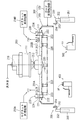
図1の基板研磨部400および基板洗浄部500は、アーム410,510の他端部に設けられる部材(研磨ヘッドphおよび洗浄ブラシcb)が異なる点を除いて基本的に同じ構成を有する。そこで、基板研磨部400および基板洗浄部500のうち、代表して基板研磨部400の構成を説明する。
[2] Details of Substrate Polishing Unit and Substrate Cleaning Unit The
図2は、図1の基板研磨部400の構成を示す模式的側面図である。図2に示すように、アーム410は、一体的に接続されたアーム一端部411、アーム本体部412およびアーム他端部413を含む。アーム支持柱420の内部には、アーム410のアーム一端部411を昇降可能に支持するアーム昇降駆動部430が設けられている。また、アーム支持柱420の内部には、アーム410およびアーム昇降駆動部430をアーム支持柱420の軸心の周りで回転可能に支持するアーム回転駆動部440が設けられている。
FIG. 2 is a schematic side view showing the configuration of the
アーム一端部411の内部には、プーリ417およびモータ418が設けられている。プーリ417は、モータ418の回転軸に接続されている。また、アーム他端部413の内部には、回転支持軸414およびプーリ415が設けられている。研磨ヘッドphは、回転支持軸414の上端部に取り付けられている。プーリ415は、回転支持軸414の下端部に取り付けられている。さらに、アーム本体部412の内部には、2つのプーリ415,417を接続するベルト416が設けられている。図1の洗浄コントローラ780の制御に基づいてモータ418が動作する。この場合、モータ418の回転力がプーリ417、ベルト416、プーリ415および回転支持軸414を通して研磨ヘッドphに伝達される。それにより、研磨ヘッドphが上下方向の軸の周りで回転する。
A
アーム昇降駆動部430は、鉛直方向に延びるリニアガイド431、エアシリンダ432および電空レギュレータ433を含む。リニアガイド431には、アーム一端部411が昇降可能に取り付けられている。この状態で、アーム一端部411がエアシリンダ432に接続されている。
The arm
エアシリンダ432は、電空レギュレータ433を通して空気が供給されることにより鉛直方向に伸縮可能に設けられている。電空レギュレータ433は、図1の洗浄コントローラ780により制御される電気制御式のレギュレータである。電空レギュレータ433からエアシリンダ432に与えられる空気の圧力に応じてエアシリンダ432の長さが変化する。それにより、アーム一端部411がエアシリンダ432の長さに応じた高さに移動する。
The
アーム回転駆動部440は、例えばモータおよび複数のギア等を含み、図1の洗浄コントローラ780により制御される。アーム支持柱420には、さらにアーム410の回転角度θ1(図1)を検出するためのエンコーダ441が設けられている。エンコーダ441は、研磨ヘッドphがヘッド待機位置p1にあるときのアーム410の延びる方向を基準としてアーム410の回転角度θ1を検出し、検出結果を示す信号を図1の洗浄コントローラ780に与える。それにより、アーム410の回転角度θ1がフィードバック制御される。
The arm
なお、基板洗浄部500は、上記のエンコーダ441に対応するエンコーダを含む。この場合、基板洗浄部500のエンコーダは、洗浄ブラシcbがブラシ待機位置p2(図1)にあるときのアーム510の延びる方向を基準としてアーム510の回転角度θ2(図1)を検出し、検出結果を示す信号を図1の洗浄コントローラ780に与える。それにより、アーム510の回転角度θ2がフィードバック制御される。
The
[3]スピンチャック、ガード機構および複数の基板受け渡し機構の詳細
図3は図1のスピンチャック200およびその周辺部材の構成を説明するための概略側面図であり、図4は図1のスピンチャック200およびその周辺部材の構成を説明するための概略平面図である。図3および図4では、スピンチャック200により保持される基板Wが太い二点鎖線で示される。
[3] Details of Spin Chuck, Guard Mechanism, and Multiple Substrate Transfer Mechanism FIG. 3 is a schematic side view for explaining the configuration of the
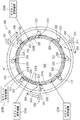
図3および図4に示すように、スピンチャック200は、スピンモータ211、円板状のスピンプレート213、プレート支持部材214、4つのマグネットプレート231A,231B,232A,232B、4つのマグネット昇降機構233A,233B,234A,234Bおよび複数のチャックピン220を含む。
As shown in FIGS. 3 and 4, the
スピンモータ211は、図1の筐体710内部の中央よりもやや上方の位置で図示しない支持部材によって支持されている。スピンモータ211は、下方に延びる回転軸212を有する。回転軸212の下端部にプレート支持部材214が取り付けられている。プレート支持部材214によりスピンプレート213が水平に支持されている。スピンモータ211が動作することにより回転軸212が回転し、スピンプレート213が鉛直軸の周りで回転する。
The
回転軸212およびプレート支持部材214には、液供給管215が挿通されている。液供給管215の一端は、プレート支持部材214の下端部よりも下方に突出する。液供給管215の他端は、図示しない流体供給系に接続される。スピンチャック200により保持される基板Wの上面上に、流体供給系から液供給管215を通して洗浄液を吐出することができる。
A
複数のチャックピン220が、回転軸212に関して等角度間隔でスピンプレート213の周縁部に設けられる。本例では、8つのチャックピン220が、回転軸212に関して45度間隔でスピンプレート213の周縁部に設けられる。各チャックピン220は、軸部221、ピン支持部222、保持部223およびマグネット224を含む。
A plurality of chuck pins 220 are provided on the peripheral edge of the
軸部221は、スピンプレート213を垂直方向に貫通するように設けられる。ピン支持部222は、軸部221の下端部から水平方向に延びるように設けられる。保持部223は、ピン支持部222の先端部から下方に突出するように設けられる。また、スピンプレート213の上面側において、軸部221の上端部にマグネット224が取り付けられている。
The
各チャックピン220は、軸部221を中心に鉛直軸の周りで回転可能であり、保持部223が基板Wの外周端部に接触する閉状態と、保持部223が基板Wの外周端部から離間する開状態とに切替可能である。なお、本例では、マグネット224のN極が内側にある場合に各チャックピン220が閉状態となり、マグネット224のS極が内側にある場合に各チャックピン220が開状態となる。
Each
スピンプレート213の上方には、図4に示すように、回転軸212を中心とする周方向に沿って並ぶように円弧状の4つのマグネットプレート231A,231B,232A,232Bが配置される。4つのマグネットプレート231A,231B,232A,232Bのうちマグネットプレート232Aは、研磨ヘッドphが移動する第1の経路pt1(後述する図6)の上方に位置する。また、マグネットプレート232Bは、洗浄ブラシcbが移動する第2の経路pt2(後述する図6)の上方に位置する。
As shown in FIG. 4, four arc-shaped
マグネットプレート231A,231B,232A,232Bの各々は、外側にS極を有し、内側にN極を有する。マグネット昇降機構233A,233B,234A,234Bは、マグネットプレート231A,231B,232A,232Bをそれぞれ昇降させる。これにより、マグネットプレート231A,231B,232A,232Bは、チャックピン220のマグネット224よりも高い上方位置とチャックピン220のマグネット224とほぼ等しい高さの下方位置との間で独立に移動可能である。
Each of the
マグネットプレート231A,231B,232A,232Bの昇降により、各チャックピン220が開状態と閉状態とに切り替えられる。具体的には、各チャックピン220は、複数のマグネットプレート231A,231B,232A,232Bのうち、最も近接するマグネットプレートが上方位置にある場合に開状態となる。一方、各チャックピン220は、最も近接するマグネットプレートが下方位置にある場合に閉状態となる。
By moving up and down the
複数の受け渡し機構350は、スピンチャック200の回転軸212を中心として等角度間隔でガード310の外方に配置される。各受け渡し機構350は、昇降回転駆動部351、回転軸352、アーム353および保持ピン354を含む。
The plurality of
回転軸352は、昇降回転駆動部351から上方に延びるように設けられる。アーム353は、回転軸352の上端部から水平方向に延びるように設けられる。保持ピン354は、基板Wの外周端部WEを保持可能にアーム353の先端部に設けられる。
The
昇降回転駆動部351により、回転軸352が回転動作を行う。それにより、基板洗浄装置700の外部に設けられる基板Wの搬送装置と複数の保持ピン354との間で基板Wの受け渡しが行われる。また、昇降回転駆動部351により、回転軸352が昇降動作および回転動作を行う。それにより、複数の保持ピン354とスピンチャック200との間で基板Wの受け渡しが行われる。
The lift
上記のように、ガード機構300は、ガード310およびガード昇降駆動部320を含む。図3では、ガード310が縦断面図で示される。ガード310は、スピンチャック200の回転軸212に関して回転対称な形状を有し、スピンチャック200およびその下方の空間よりも外方に設けられる。
As described above, the
ガード昇降駆動部320は、ガード310を昇降可能に構成され、基板Wの洗浄および乾燥が行われていないときに、スピンチャック200よりも下方の高さにガード310を保持する。一方、ガード昇降駆動部320は、基板Wの洗浄および乾燥が行われているときに、スピンチャック200により保持される基板Wと同じ高さにガード310を保持する。それにより、ガード310は、基板Wの洗浄および乾燥時に、基板Wから飛散する洗浄液を受け止める。
The guard elevating and lowering
[4]基板洗浄装置の制御系
図5は図1の基板洗浄装置700の制御系統の構成の一部を示すブロック図である。図5には、洗浄コントローラ780の機能的な構成の一部が示される。洗浄コントローラ780は、位置情報記憶部785、速度情報記憶部786、研磨洗浄制御部790およびブラシ洗浄制御部795を含む。図5の洗浄コントローラ780の各部の機能は、CPUが制御プログラムを実行することにより実現される。
[4] Control System of Substrate Cleaning Apparatus FIG. 5 is a block diagram showing a part of the configuration of the control system of the
位置情報記憶部785は、主として洗浄コントローラ780のROMまたはRAMの一部で構成され、上記の位置情報を記憶する。速度情報記憶部786は、主として洗浄コントローラ780のROMまたはRAMの一部で構成され、基板洗浄装置700内で基板Wが洗浄される際の研磨ヘッドphの移動速度および洗浄ブラシcbの移動速度を速度情報として記憶する。
The position
以下の説明では、速度情報として記憶される研磨ヘッドphおよび洗浄ブラシcbの移動速度のうち、研磨ヘッドphが基板Wの中心から外周端部へ移動するときの移動速度を第1の移動速度と呼ぶ。また、洗浄ブラシcbが基板Wの外周端部から基板Wの中心へ移動するときの移動速度を第2の移動速度と呼ぶ。 In the following description, of the moving speeds of the polishing head ph and the cleaning brush cb stored as speed information, the moving speed when the polishing head ph moves from the center of the substrate W to the outer peripheral end is referred to as the first moving speed. Call. Further, the moving speed when the cleaning brush cb moves from the outer peripheral end of the substrate W to the center of the substrate W is referred to as a second moving speed.
研磨洗浄制御部790は、回転制御部791、昇降制御部792、アーム制御部793および位置判定部794を含む。回転制御部791は、基板研磨部400のモータ418を制御することにより、研磨ヘッドph(図1)の回転速度を調整する。昇降制御部792は、基板研磨部400の電空レギュレータ433を制御することにより研磨ヘッドph(図1)の高さを調整する。アーム制御部793は、図5の速度情報記憶部786に記憶された速度情報と基板研磨部400のエンコーダ441からの信号とに基づいてアーム回転駆動部440を制御する。それにより、研磨ヘッドphが第1の移動速度で後述する第1の経路pt1(図6)を移動する。
The polishing/
位置判定部794は、位置情報記憶部785に記憶された位置情報と基板研磨部400のエンコーダ441からの信号とに基づいて、基板Wの中心から基板Wの外周端部へ移動する研磨ヘッドphが後述する干渉領域if(図6)から外れたか否かを判定する。また、位置判定部794は、判定結果をブラシ洗浄制御部795に与える。
The
ブラシ洗浄制御部795は、位置判定部794を含まない点を除いて基本的に研磨洗浄制御部790と同じ構成を有する。ブラシ洗浄制御部795は、研磨洗浄制御部790と基板研磨部400との関係と同様に、基板洗浄部500の各部の動作を制御する。それにより、洗浄ブラシcbが第2の移動速度で後述する第2の経路pt2(図6)を移動する。
The brush
また、ブラシ洗浄制御部795は、研磨洗浄制御部790の位置判定部794から与えられる判定結果に基づいて、研磨ヘッドphが干渉領域if(図6)から外れたときに、基板Wの外周端部から基板Wの中心への洗浄ブラシcbの移動を開始させる。この制御の詳細は後述する。
In addition, the brush
[5]基板洗浄装置による基板の下面の研磨洗浄およびブラシ洗浄
図1の基板洗浄装置700においては、基板Wが筐体710内に搬入された後、スピンチャック200により保持される基板Wの上面が洗浄される。基板Wの上面を洗浄する際には、スピンチャック200の全てのチャックピン220により基板Wの外周端部が保持されつつ基板Wが回転される状態で、図3の液供給管215を通して基板Wの上面に洗浄液が供給される。洗浄液は遠心力によって基板Wの上面の全体に広がり、外方に飛散する。これにより、基板Wの上面に付着する塵埃等が洗い流される。その後、上記の位置情報および速度情報を用いて基板Wの下面の研磨洗浄および基板Wの下面のブラシ洗浄が実行される。
[5] Polishing Cleaning and Brush Cleaning of Lower Surface of Substrate by Substrate Cleaning Device In the
ここで、位置情報について説明する。図6は、干渉領域および位置情報を説明するための平面図である。図6では、基板研磨部400および基板洗浄部500が示されるとともに、図1のスピンチャック200により保持される基板Wが仮想的に太い二点鎖線で示される。
Here, the position information will be described. FIG. 6 is a plan view for explaining the interference area and the position information. In FIG. 6, the
図6に太い一点鎖線で示すように、回転される基板Wに対して基板研磨部400の研磨ヘッドphの中心が移動する第1の経路pt1が規定される。第1の経路pt1は、例えばアーム410の寸法等に応じて定まり、スピンチャック200により回転される基板Wの中心WCと外周端部WEとを結ぶようにかつヘッド待機位置p1の中心まで延びるように円弧状に延びている。研磨ヘッドphの中心が第1の経路pt1に沿って移動することにより、図6に一点鎖線で示すように、研磨ヘッドphの第1の軌跡lc1が形成される。
As indicated by the thick dashed line in FIG. 6, the first path pt1 along which the center of the polishing head ph of the
また、図6に太い点線で示すように、回転される基板Wに対して基板洗浄部500の洗浄ブラシcbの中心が移動する第2の経路pt2が規定される。第2の経路pt2は、例えばアーム510の寸法等に応じて定まり、スピンチャック200により回転される基板Wの中心WCと外周端部WEとを結ぶようにかつブラシ待機位置p2の中心まで延びるように円弧状に延びている。洗浄ブラシcbの中心が第2の経路pt2に沿って移動することにより、図6に点線で示すように、洗浄ブラシcbの第2の軌跡lc2が形成される。
Further, as indicated by a thick dotted line in FIG. 6, a second path pt2 along which the center of the cleaning brush cb of the
研磨ヘッドphおよび洗浄ブラシcbのうちのいずれかが、第1の軌跡lc1と第2の軌跡lc2との重複領域に存在すると、基板研磨部400および基板洗浄部500の動作によっては研磨ヘッドphと洗浄ブラシcbとが互いに干渉する可能性がある。そこで、太い実線とハッチングで示すように、第1の軌跡lc1と第2の軌跡lc2との重複領域を干渉領域ifとして定義する。
If any one of the polishing head ph and the cleaning brush cb exists in the overlapping region of the first locus lc1 and the second locus lc2, the polishing head ph and the cleaning head ph may differ depending on the operations of the
上記のように、干渉領域ifに対応して位置情報が定められる。位置情報は、研磨ヘッドphが基板Wの中心WCから基板Wの外周端部WEに向かって移動することにより研磨ヘッドphが干渉領域ifから外れる時点の研磨ヘッドphの位置を示す情報である。本実施の形態においては、研磨ヘッドphが干渉領域ifから外れる時点のアーム410の回転角度θ1が位置情報として設定される。
As described above, the position information is set corresponding to the interference area if. The position information is information indicating the position of the polishing head ph at the time when the polishing head ph moves out of the interference region if as the polishing head ph moves from the center WC of the substrate W toward the outer peripheral end WE of the substrate W. In the present embodiment, the rotation angle θ1 of the
以下の説明においては、研磨ヘッドphが基板Wの外周端部WE上に位置するときのアーム410の回転角度θ1を「α」とし、研磨ヘッドphが基板Wの中心WC上に位置するときのアーム410の回転角度θ1を「γ」とする。また、研磨ヘッドphが基板Wの中心WCから外周端部WEに向かって移動することにより研磨ヘッドphが干渉領域ifから外れた時点のアーム410の回転角度θ1を「β」とする。この場合、「β」が位置情報として洗浄コントローラ780の位置情報記憶部785に記憶される。
In the following description, the rotation angle θ1 of the
位置情報は、研磨ヘッドphの位置を特定することが可能な情報であればよい。したがって、位置情報として、アーム410の回転角度θ1以外のパラメータが用いられてもよい。例えば、図5のアーム回転駆動部440がパルスモータで構成される場合には、アーム410の回転角度θ1に代えてアーム回転駆動部440に与えられるパルスの数が位置情報として用いられてもよい。
The position information may be any information that can specify the position of the polishing head ph. Therefore, parameters other than the rotation angle θ1 of the
ここで、基板研磨部400および基板洗浄部500は、スピンチャック200により保持される基板Wの回転中心を通って前後方向に延びる鉛直面を基準として対称に配置される。そのため、本例では、洗浄ブラシcbが基板Wの外周端部WE上に位置するときのアーム510の回転角度θ2が「α」となり、洗浄ブラシcbが基板Wの中心WC上に位置するときのアーム510の回転角度θ2が「γ」となる。また、洗浄ブラシcbが基板Wの中心WCから外周端部WEに向かって移動することにより洗浄ブラシcbが干渉領域ifから外れた時点のアーム510の回転角度θ2が「β」となる。
Here, the
位置情報を用いた基板Wの下面の研磨洗浄および基板Wの下面のブラシ洗浄の詳細を洗浄コントローラ780の動作とともに説明する。図7は研磨洗浄およびブラシ洗浄を行う際の洗浄コントローラ780の制御動作を示すフローチャートであり、図8は図7の一連の処理に対応して変化する基板研磨部400および基板洗浄部500の状態を示す図である。
The details of the polishing cleaning of the lower surface of the substrate W and the brush cleaning of the lower surface of the substrate W using the position information will be described together with the operation of the cleaning
図8(a)に、アーム410,510の回転角度θ1,θ2の変化がタイムチャートで示される。図8(a)のタイムチャートにおいては、太い実線がアーム410の回転角度θ1の変化を表し、太い一点鎖線がアーム510の回転角度θ2の変化を表す。図8(b)〜(i)に、図8(a)のタイムチャート上の複数の時点における基板研磨部400および基板洗浄部500のアーム410,510の状態が模式的な平面図で示される。また、図8(b)〜(i)の平面図では、基板Wが二点鎖線で仮想的に示される。
FIG. 8A is a time chart showing changes in the rotation angles θ1 and θ2 of the
研磨洗浄およびブラシ洗浄を開始する図8の時点t0では、スピンチャック200により保持された基板Wが予め定められた速度で回転しているものとする。また、基板研磨部400のノズル410Nおよび基板洗浄部500のノズル510Nには、それぞれ洗浄液が供給されていないものとする。
It is assumed that the substrate W held by the
さらに、図8(b)に示すように、基板研磨部400の研磨ヘッドphおよび基板洗浄部500の洗浄ブラシcbは、基板Wよりも下方の高さでそれぞれヘッド待機位置p1およびブラシ待機位置p2に位置する。このとき、アーム410の回転角度θ1は「0」であり、アーム510の回転角度θ2も「0」である。
Further, as shown in FIG. 8B, the polishing head ph of the
まず、洗浄コントローラ780は、研磨ヘッドphおよび洗浄ブラシcbを基板Wの外周端部WEの下方の位置まで移動させる(ステップS101)。それにより、図8(a),(c)に示すように、研磨ヘッドphおよび洗浄ブラシcbがそれぞれ時点t1で基板Wの外周端部WEの下方の位置に到達する。このとき、アーム410の回転角度θ1は「α」であり、アーム510の回転角度θ2も「α」である。
First, the cleaning
次に、洗浄コントローラ780は、研磨ヘッドphを基板Wの中心WCに対向する位置までさらに移動させる(ステップS102)。この場合、洗浄ブラシcbは、基板Wの外周端部WEの下方の位置で待機状態となる。それにより、図8(a),(c),(d)に示すように、時点t1〜時点t2にかけて、研磨ヘッドphが洗浄ブラシcbと干渉することなく基板Wの中心WCに対向する位置まで移動する。時点t2においては、アーム410の回転角度θ1は「γ」である。
Next, the cleaning
次に、洗浄コントローラ780は、研磨ヘッドphを基板Wの下面に接触させるとともに基板Wの外周端部WEに向かう研磨ヘッドphの移動を開始させる(ステップS103)。具体的には、図8の時点t2〜時点t3にかけて、研磨ヘッドphが基板Wの下面に接触するまで上昇する。時点t3において研磨ヘッドphが基板Wの下面に接触することにより基板Wの下面の中心WCが研磨ヘッドphにより研磨される。このとき、研磨ヘッドphは干渉領域if上に位置する。その後、図8(e),(f),(g)に示すように、研磨ヘッドphが基板Wの外周端部WE上まで移動する。このときの移動速度は、速度情報として予め定められた第1の移動速度に調整される。これにより、時点t3〜時点t6にかけて基板Wの下面が中心WCから外周端部WEに向かって研磨される。時点t6においては、アーム410の回転角度θ1は「α」である。時点t3〜時点t6の間、ノズル410Nから基板Wに洗浄液が供給される。それにより、研磨により基板Wの下面から剥ぎ取られる汚染物が洗浄液により洗い流される。
Next, the cleaning
なお、時点t6で研磨ヘッドphが基板Wの外周端部WEに到達する際には、研磨ヘッドphと複数のチャックピン220とが干渉する可能性がある。そこで、本例では、研磨ヘッドphが基板Wの外周端部WEに到達する際に、図4のマグネット昇降機構234Aにより図4のマグネットプレート232Aが一時的に下方位置から上方位置に移動する。それにより、スピンチャック200の各チャックピン220は、マグネットプレート232Aに対応する領域で局部的に開状態となる。マグネットプレート232Aは研磨ヘッドphの第1の経路pt1(図6)の上方に位置するので、研磨ヘッドphが複数のチャックピン220に干渉することが防止される。
When the polishing head ph reaches the outer peripheral edge portion WE of the substrate W at time t6, the polishing head ph and the plurality of chuck pins 220 may interfere with each other. Therefore, in this example, when the polishing head ph reaches the outer peripheral end portion WE of the substrate W, the
ステップS103による研磨ヘッドphの移動中に、洗浄コントローラ780は、図5のエンコーダ441から与えられる信号と上記の位置情報とに基づいて、研磨ヘッドphが干渉領域ifから外れたか否かを判定する(ステップS104)。この判定処理は一定周期で繰り返される。洗浄コントローラ780は、エンコーダ441により検出されるアーム410の回転角度θ1が図6の「β」よりも大きいときに研磨ヘッドphが干渉領域if内にあると判定する。また、洗浄コントローラ780は、エンコーダ441により検出されるアーム410の回転角度θ1が図6の「β」以下であるときに研磨ヘッドphが干渉領域ifから外れたと判定する。
During the movement of the polishing head ph in step S103, the cleaning
本例では、図8(a),(e)に示すように、時点t4で研磨ヘッドphが干渉領域ifから外れる。このとき、アーム410の回転角度θ1は「β」である。研磨ヘッドphが干渉領域ifから外れていると、洗浄ブラシcbが基板Wの中心WCに向かって移動しても、研磨ヘッドphと洗浄ブラシcbとが干渉しない。
In this example, as shown in FIGS. 8A and 8E, the polishing head ph moves out of the interference region if at time t4. At this time, the rotation angle θ1 of the
そこで、洗浄コントローラ780は、研磨ヘッドphが干渉領域ifから外れたと判定すると、その時点で基板Wの外周端部WEの下方の位置から基板Wの下面の中心WCに対向する位置へ向かう洗浄ブラシcbの移動を開始させる(ステップS105)。これにより、本例では、図8(a),(e)に示すように、時点t4で洗浄ブラシcbが基板Wの外周端部WEの下方の位置から基板Wの下面の中心WCに対向する位置への移動を開始する。なお、洗浄コントローラ780は、ステップS104で研磨ヘッドphが干渉領域if内にあると判定した場合、ステップS104の処理を繰り返す。
Therefore, when the cleaning
洗浄ブラシcbが基板Wの外周端部WEの下方の位置から基板Wの下面の中心WCに対向する位置へ移動するときの移動速度は、速度情報に基づいて予め定められた第2の移動速度に調整される。ここで、洗浄ブラシcbが基板Wから離間した状態で移動する場合には、基板Wが洗浄ブラシcbにより擦られることがないので、洗浄ブラシcbの移動速度を最大限に設定することができる。したがって、第2の移動速度は、研磨ヘッドphが基板Wの下面を研磨しつつ移動するときの研磨ヘッドphの第1の移動速度に比べて十分高く設定される。そのため、図8(a),(f)に示すように、本例では、研磨ヘッドphが基板Wの外周端部WEに到達する時点t6の前の時点t5で、洗浄ブラシcbが基板Wの下面の中心WCに対向する位置に到達する。このとき、アーム510の回転角度θ2は「γ」である。
The moving speed when the cleaning brush cb moves from a position below the outer peripheral edge WE of the substrate W to a position facing the center WC of the lower surface of the substrate W is a second moving speed that is predetermined based on the speed information. Is adjusted to. Here, when the cleaning brush cb moves away from the substrate W, the substrate W is not rubbed by the cleaning brush cb, so that the moving speed of the cleaning brush cb can be set to the maximum. Therefore, the second moving speed is set sufficiently higher than the first moving speed of the polishing head ph when the polishing head ph moves while polishing the lower surface of the substrate W. Therefore, as shown in FIGS. 8A and 8F, in this example, at the time t5 before the time t6 when the polishing head ph reaches the outer peripheral edge WE of the substrate W, the cleaning brush cb moves the substrate W to It reaches a position facing the center WC of the lower surface. At this time, the rotation angle θ2 of the
次に、洗浄コントローラ780は、洗浄ブラシcbを基板Wの下面に接触させるとともに洗浄ブラシcbを基板Wの外周端部WEに向けて移動させる(ステップS106)。具体的には、図8の時点t5から一定時間で洗浄ブラシcbが基板Wの下面に接触するまで上昇する。洗浄ブラシcbが基板Wの下面に接触することにより基板Wの下面の中心WCが洗浄ブラシcbにより洗浄される。その後、図8(g),(h),(i)に示すように、時点t6〜時点t9にかけて洗浄ブラシcbが基板Wの外周端部WE上まで移動し、基板Wの下面が洗浄ブラシcbにより洗浄される。なお、洗浄ブラシcbの移動は、洗浄ブラシcbが基板Wの下面に接触すると同時に開始されてもよい。洗浄ブラシcbが基板Wの下面に接触する時点t6〜時点t9の間、ノズル510Nから基板Wに洗浄液が供給される。それにより、研磨により基板Wの下面から剥ぎ取られる汚染物が洗浄液により洗い流される。
Next, the cleaning
なお、時点t9で洗浄ブラシcbが基板Wの外周端部WEに到達する際には、洗浄ブラシcbと複数のチャックピン220とが干渉する可能性がある。そこで、本例では、洗浄ブラシcbが基板Wの外周端部WEに到達する際に、図4のマグネット昇降機構234Bにより図4のマグネットプレート232Bが一時的に下方位置から上方位置に移動する。それにより、スピンチャック200の各チャックピン220は、マグネットプレート232Bに対応する領域で局部的に開状態となる。マグネットプレート232Bは洗浄ブラシcbの第2の経路pt2(図6)の上方に位置するので、洗浄ブラシcbが複数のチャックピン220に干渉することが防止される。
When the cleaning brush cb reaches the outer peripheral edge WE of the substrate W at time t9, the cleaning brush cb and the plurality of chuck pins 220 may interfere with each other. Therefore, in this example, when the cleaning brush cb reaches the outer peripheral end WE of the substrate W, the
洗浄コントローラ780は、研磨ヘッドphが基板Wの外周端部WEに到達すると、研磨ヘッドphが基板Wから離間するように研磨ヘッドphを下降させ、研磨ヘッドphをヘッド待機位置p1へ戻す(ステップS107)。本例では、図8(a),(g),(h)に示すように、時点t6〜時点t7にかけて研磨ヘッドphが基板Wから離間し、時点t7〜時点t8にかけて研磨ヘッドphがヘッド待機位置p1に戻る。
When the polishing head ph reaches the outer peripheral edge portion WE of the substrate W, the cleaning
さらに、洗浄コントローラ780は、洗浄ブラシcbが基板Wの外周端部WEに到達すると、洗浄ブラシcbが基板Wから離間するように洗浄ブラシcbを下降させ、洗浄ブラシcbをブラシ待機位置p2へ戻す(ステップS108)。本例では、図8(a),(i)に示すように、時点t9〜時点t10にかけて洗浄ブラシcbが基板Wから離間し、時点t10〜時点t11にかけて洗浄ブラシcbがブラシ待機位置p2に戻る。それにより、基板Wの下面の研磨洗浄およびブラシ洗浄が終了する。
Further, when the cleaning brush cb reaches the outer peripheral end WE of the substrate W, the cleaning
図7の一連の処理のうち、ステップS106,S107,S108の処理は、上記の順に行われる必要はない。ステップS107の処理が、ステップS106の前に行われてもよい。あるいは、ステップS106,S107,S108の処理は一部の処理が他の処理と並行して行われてもよい。なお、以下の説明においては、図7の一連の処理のうち、点線で囲まれるステップS103,S104,S105の一連の処理を干渉防止基本制御と呼ぶ。 Of the series of processes in FIG. 7, the processes of steps S106, S107, and S108 need not be performed in the above order. The process of step S107 may be performed before step S106. Alternatively, some of the processes of steps S106, S107, and S108 may be performed in parallel with other processes. In the following description, the series of steps S103, S104, and S105 enclosed by the dotted line in the series of processing in FIG. 7 will be referred to as interference prevention basic control.
基板Wの上面の洗浄、基板Wの下面の研磨洗浄および基板Wの下面のブラシ洗浄の終了後、基板Wの乾燥処理が行われる。基板Wの乾燥処理では、全てのチャックピン220により基板Wが保持された状態で、その基板Wが高速で回転される。それにより、基板Wに付着する洗浄液が振り切られ、基板Wが乾燥する。基板Wの乾燥処理が終了することにより、基板Wが筐体710から搬出される。
After the cleaning of the upper surface of the substrate W, the polishing cleaning of the lower surface of the substrate W, and the brush cleaning of the lower surface of the substrate W are completed, the drying processing of the substrate W is performed. In the drying process of the substrate W, the substrate W is rotated at a high speed while the substrate W is held by all the chuck pins 220. Thereby, the cleaning liquid adhering to the substrate W is shaken off and the substrate W is dried. When the drying process of the substrate W is completed, the substrate W is unloaded from the
上記の例では、洗浄ブラシcbが基板Wに接触するための上昇を開始する時点は、洗浄ブラシcbが基板Wの下面の中心WCの下方の位置に到達する時点t5に設定されている。この例に限らず、洗浄ブラシcbが上昇を開始する時点は、研磨ヘッドphが基板Wの外周端部WEに到達する時点t6に設定されてもよいし、時点t5〜時点t6の間の任意の時点に設定されてもよい。 In the above example, the time point at which the cleaning brush cb starts to move up to come into contact with the substrate W is set to the time point t5 at which the cleaning brush cb reaches the position below the center WC of the lower surface of the substrate W. Not limited to this example, the time when the cleaning brush cb starts to rise may be set to time t6 when the polishing head ph reaches the outer peripheral end WE of the substrate W, or may be set arbitrarily between time t5 and time t6. May be set at the time point of.
上記の例では、洗浄ブラシcbがブラシ洗浄を行いつつ基板Wの外周端部WEに向かう移動の開始時点は、研磨ヘッドphが基板Wの外周端部WEに到達する時点t6に設定されている。この例に限らず、洗浄ブラシcbが基板Wの外周端部WEに向かう移動の開始時点は、洗浄ブラシcbが上昇することにより基板Wの中心WCに接触する時点に設定されてもよいし、洗浄ブラシcbが基板Wに接触してから時点t6までの任意の時点に設定されてもよい。この場合、基板Wの下面上では、一部の環状領域が研磨ヘッドphにより研磨洗浄されると同時に、一部の環状領域よりも内側の他の領域が洗浄ブラシcbによりブラシ洗浄される。 In the above example, the time point at which the cleaning brush cb starts moving toward the outer peripheral edge WE of the substrate W while performing brush cleaning is set to the time t6 when the polishing head ph reaches the outer peripheral edge WE of the substrate W. .. Not limited to this example, the start point of the movement of the cleaning brush cb toward the outer peripheral edge WE of the substrate W may be set to the point of contact with the center WC of the substrate W as the cleaning brush cb rises, The time may be set to any time from the time when the cleaning brush cb contacts the substrate W to the time t6. In this case, on the lower surface of the substrate W, a part of the annular region is polished and cleaned by the polishing head ph, and at the same time, another region inside the part of the annular region is brush-cleaned by the cleaning brush cb.
[6]基板処理装置
(a)基板処理装置の構成の概略
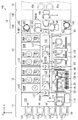
図9は、図1の基板洗浄装置700を備えた基板処理装置の模式的平面図である。図9および後述する図10〜図12には、位置関係を明確にするために互いに直交するX方向、Y方向およびZ方向を示す矢印を付している。X方向およびY方向は水平面内で互いに直交し、Z方向は鉛直方向に相当する。
[6] Substrate Processing Apparatus (a) Outline of Configuration of Substrate Processing Apparatus FIG. 9 is a schematic plan view of a substrate processing apparatus including the
図9に示すように、基板処理装置100は、インデクサブロック11、第1の処理ブロック12、第2の処理ブロック13、洗浄乾燥処理ブロック14Aおよび搬入搬出ブロック14Bを備える。洗浄乾燥処理ブロック14Aおよび搬入搬出ブロック14Bにより、インターフェイスブロック14が構成される。搬入搬出ブロック14Bに隣接するように露光装置15が配置される。露光装置15においては、液浸法により基板Wに露光処理が行われる。
As shown in FIG. 9, the
インデクサブロック11は、複数のキャリア載置部111および搬送部112を含む。各キャリア載置部111には、複数の基板Wを多段に収納するキャリア113が載置される。
The
搬送部112には、メインコントローラ114および搬送装置115が設けられる。メインコントローラ114は、基板処理装置100の種々の構成要素を制御する。搬送装置115は、基板Wを保持しつつその基板Wを搬送する。
The
第1の処理ブロック12は、塗布処理部121、搬送部122および熱処理部123を含む。塗布処理部121および熱処理部123は、搬送部122を挟んで対向するように設けられる。搬送部122とインデクサブロック11との間には、基板Wが載置される基板載置部PASS1および後述する基板載置部PASS2〜PASS4(図12参照)が設けられる。搬送部122には、基板Wを搬送する搬送装置127および後述する搬送装置128(図12参照)が設けられる。
The
第2の処理ブロック13は、塗布現像処理部131、搬送部132および熱処理部133を含む。塗布現像処理部131および熱処理部133は、搬送部132を挟んで対向するように設けられる。搬送部132と搬送部122との間には、基板Wが載置される基板載置部PASS5および後述する基板載置部PASS6〜PASS8(図12参照)が設けられる。搬送部132には、基板Wを搬送する搬送装置137および後述する搬送装置138(図12参照)が設けられる。
The
洗浄乾燥処理ブロック14Aは、洗浄乾燥処理部161,162および搬送部163を含む。洗浄乾燥処理部161,162は、搬送部163を挟んで対向するように設けられる。搬送部163には、搬送装置141,142が設けられる。
The cleaning/
搬送部163と搬送部132との間には、載置兼バッファ部P−BF1および後述の載置兼バッファ部P−BF2(図12参照)が設けられる。
A placement/buffer section P-BF1 and a placement/buffer section P-BF2 (see FIG. 12) described later are provided between the
また、搬送装置141,142の間において、搬入搬出ブロック14Bに隣接するように、基板載置部PASS9および後述の載置兼冷却部P−CP(図12参照)が設けられる。
Further, between the
搬入搬出ブロック14Bには、搬送装置146が設けられる。搬送装置146は、露光装置15に対する基板Wの搬入および搬出を行う。露光装置15には、基板Wを搬入するための基板搬入部15aおよび基板Wを搬出するための基板搬出部15bが設けられる。
The carry-in/carry-out
(b)塗布処理部および塗布現像処理部の構成
図10は、主として図9の塗布処理部121、塗布現像処理部131および洗浄乾燥処理部161を示す基板処理装置100の模式的側面図である。
(B) Configuration of Coating Processing Section and Coating Development Processing Section FIG. 10 is a schematic side view of the
図10に示すように、塗布処理部121には、塗布処理室21,22,23,24が階層的に設けられる。塗布処理室21〜24の各々には、塗布処理ユニット(スピンコータ)129が設けられる。塗布現像処理部131には、現像処理室31,33および塗布処理室32,34が階層的に設けられる。現像処理室31,33の各々には現像処理ユニット(スピンデベロッパ)139が設けられ、塗布処理室32,34の各々には塗布処理ユニット129が設けられる。
As shown in FIG. 10, the
各塗布処理ユニット129は、基板Wを保持するスピンチャック25およびスピンチャック25の周囲を覆うように設けられるカップ27を備える。本実施の形態では、各塗布処理ユニット129に2組のスピンチャック25およびカップ27が設けられる。スピンチャック25は、図示しない駆動装置(例えば、電動モータ)により回転駆動される。また、図9に示すように、各塗布処理ユニット129は、処理液を吐出する複数の処理液ノズル28およびその処理液ノズル28を搬送するノズル搬送機構29を備える。
Each
塗布処理ユニット129においては、図示しない駆動装置によりスピンチャック25が回転されるとともに、複数の処理液ノズル28のうちのいずれかの処理液ノズル28がノズル搬送機構29により基板Wの上方に移動され、その処理液ノズル28から処理液が吐出される。それにより、基板W上に処理液が塗布される。また、図示しないエッジリンスノズルから、基板Wの周縁部にリンス液が吐出される。それにより、基板Wの周縁部に付着する処理液が除去される。
In the
塗布処理室22,24の塗布処理ユニット129においては、反射防止膜用の処理液が処理液ノズル28から基板Wに供給される。塗布処理室21,23の塗布処理ユニット129においては、レジスト膜用の処理液が処理液ノズル28から基板Wに供給される。塗布処理室32,34の塗布処理ユニット129においては、レジストカバー膜用の処理液が処理液ノズル28から基板Wに供給される。
In the
現像処理ユニット139は、塗布処理ユニット129と同様に、スピンチャック35およびカップ37を備える。また、図9に示すように、現像処理ユニット139は、現像液を吐出する2つの現像ノズル38およびその現像ノズル38をX方向に移動させる移動機構39を備える。
The
現像処理ユニット139においては、図示しない駆動装置によりスピンチャック35が回転されるとともに、一方の現像ノズル38がX方向に移動しつつ各基板Wに現像液を供給し、その後、他方の現像ノズル38が移動しつつ各基板Wに現像液を供給する。この場合、基板Wに現像液が供給されることにより、基板Wの現像処理が行われる。また、本実施の形態においては、2つの現像ノズル38から互いに異なる現像液が吐出される。それにより、各基板Wに2種類の現像液を供給することができる。
In the developing
洗浄乾燥処理部161には、洗浄乾燥処理室81,82,83,84が階層的に設けられる。洗浄乾燥処理室81〜84の各々に、図1の基板洗浄装置700が設けられる。基板洗浄装置700においては、露光処理前の基板Wの上面の洗浄、下面の研磨洗浄、下面のブラシ洗浄および乾燥処理が行われる。
The cleaning/
ここで、洗浄乾燥処理部161に設けられる複数の基板洗浄装置700の洗浄コントローラ780は、洗浄乾燥処理部161の上部にローカルコントローラとして設けられてもよい。あるいは、図9のメインコントローラ114が、複数の基板洗浄装置700の洗浄コントローラ780により実行される各種処理を実行してもよい。
Here, the cleaning
図9および図10に示すように、塗布処理部121において塗布現像処理部131に隣接するように流体ボックス部50が設けられる。同様に、塗布現像処理部131において洗浄乾燥処理ブロック14Aに隣接するように流体ボックス部60が設けられる。流体ボックス部50および流体ボックス部60内には、塗布処理ユニット129および現像処理ユニット139への処理液および現像液の供給ならびに塗布処理ユニット129および現像処理ユニット139からの排液および排気等に関する流体関連機器が収納される。流体関連機器は、導管、継ぎ手、バルブ、流量計、レギュレータ、ポンプ、温度調節器等を含む。
As shown in FIGS. 9 and 10, the
(c)熱処理部の構成
図11は、主として図9の熱処理部123,133および洗浄乾燥処理部162を示す基板処理装置100の模式的側面図である。図11に示すように、熱処理部123は、上方に設けられる上段熱処理部301および下方に設けられる下段熱処理部302を有する。上段熱処理部301および下段熱処理部302には、複数の熱処理装置PHP、複数の密着強化処理ユニットPAHPおよび複数の冷却ユニットCPが設けられる。
(C) Configuration of Heat Treatment Section FIG. 11 is a schematic side view of the
熱処理装置PHPにおいては、基板Wの加熱処理が行われる。密着強化処理ユニットPAHPにおいては、基板Wと反射防止膜との密着性を向上させるための密着強化処理が行われる。具体的には、密着強化処理ユニットPAHPにおいて、基板WにHMDS(ヘキサメチルジシラザン)等の密着強化剤が塗布されるとともに、基板Wに加熱処理が行われる。冷却ユニットCPにおいては、基板Wの冷却処理が行われる。 The heat treatment of the substrate W is performed in the heat treatment apparatus PHP. In the adhesion strengthening processing unit PAHP, the adhesion strengthening processing for improving the adhesion between the substrate W and the antireflection film is performed. Specifically, in the adhesion reinforcement processing unit PAHP, with adhesion reinforcing agent such as HMDS (hexamethyl The emission) is applied to the substrate W, the heat treatment to the substrate W is performed. The cooling process of the substrate W is performed in the cooling unit CP.
熱処理部133は、上方に設けられる上段熱処理部303および下方に設けられる下段熱処理部304を有する。上段熱処理部303および下段熱処理部304には、冷却ユニットCP、複数の熱処理装置PHPおよびエッジ露光部EEWが設けられる。
The
エッジ露光部EEWにおいては、基板W上に形成されたレジスト膜の周縁部の一定幅の領域に露光処理(エッジ露光処理)が行われる。上段熱処理部303および下段熱処理部304において、洗浄乾燥処理ブロック14Aに隣り合うように設けられる熱処理装置PHPは、洗浄乾燥処理ブロック14Aからの基板Wの搬入が可能に構成される。
In the edge exposure unit EEW, an exposure process (edge exposure process) is performed on a region of a constant width at the peripheral edge of the resist film formed on the substrate W. In the upper
洗浄乾燥処理部162には、洗浄乾燥処理室91,92,93,94,95が階層的に設けられる。洗浄乾燥処理室91〜95の各々には、洗浄乾燥処理ユニットSD2が設けられる。洗浄乾燥処理ユニットSD2は、基板研磨部400が設けられない点および図4のマグネットプレート231A,231B,232Aが一体的に設けられる点を除いて基板洗浄装置700と同じ構成を有する。洗浄乾燥処理ユニットSD2においては、露光処理後の基板Wの上面の洗浄、下面のブラシ洗浄および乾燥処理が行われる。
The cleaning/
(d)搬送部の構成
図12は、主として図9の搬送部122,132,163を示す側面図である。図12に示すように、搬送部122は、上段搬送室125および下段搬送室126を有する。搬送部132は、上段搬送室135および下段搬送室136を有する。上段搬送室125には搬送装置(搬送ロボット)127が設けられ、下段搬送室126には搬送装置128が設けられる。また、上段搬送室135には搬送装置137が設けられ、下段搬送室136には搬送装置138が設けられる。
(D) Configuration of Transport Unit FIG. 12 is a side view mainly showing the
搬送部112と上段搬送室125との間には、基板載置部PASS1,PASS2が設けられ、搬送部112と下段搬送室126との間には、基板載置部PASS3,PASS4が設けられる。上段搬送室125と上段搬送室135との間には、基板載置部PASS5,PASS6が設けられ、下段搬送室126と下段搬送室136との間には、基板載置部PASS7,PASS8が設けられる。
Substrate platforms PASS1 and PASS2 are provided between the
上段搬送室135と搬送部163との間には、載置兼バッファ部P−BF1が設けられ、下段搬送室136と搬送部163との間には載置兼バッファ部P−BF2が設けられる。搬送部163において搬入搬出ブロック14Bと隣接するように、基板載置部PASS9および複数の載置兼冷却部P−CPが設けられる。
A placement/buffer section P-BF1 is provided between the upper
搬送装置127は、基板載置部PASS1,PASS2,PASS5,PASS6、塗布処理室21,22(図10)および上段熱処理部301(図11)の間で基板Wを搬送可能に構成される。搬送装置128は、基板載置部PASS3,PASS4,PASS7,PASS8、塗布処理室23,24(図10)および下段熱処理部302(図11)の間で基板Wを搬送可能に構成される。
The
搬送装置137は、基板載置部PASS5,PASS6、載置兼バッファ部P−BF1、現像処理室31(図10)、塗布処理室32(図10)および上段熱処理部303(図11)の間で基板Wを搬送可能に構成される。搬送装置138は、基板載置部PASS7,PASS8、載置兼バッファ部P−BF2、現像処理室33(図10)、塗布処理室34(図10)および下段熱処理部304(図11)の間で基板Wを搬送可能に構成される。
The
搬送部163の搬送装置141(図9)は、載置兼冷却部P−CP、基板載置部PASS9、載置兼バッファ部P−BF1,P−BF2および洗浄乾燥処理部161(図10)の間で基板Wを搬送可能に構成される。
The transfer device 141 (FIG. 9) of the
搬送部163の搬送装置142(図9)は、載置兼冷却部P−CP、基板載置部PASS9、載置兼バッファ部P−BF1,P−BF2、洗浄乾燥処理部162(図11)、上段熱処理部303(図11)および下段熱処理部304(図11)の間で基板Wを搬送可能に構成される。
The transfer device 142 (FIG. 9) of the
(e)基板処理装置の動作
図9〜図12を参照しながら基板処理装置100の動作を説明する。インデクサブロック11のキャリア載置部111(図9)に、未処理の基板Wが収容されたキャリア113が載置される。搬送装置115は、キャリア113から基板載置部PASS1,PASS3(図12)に未処理の基板Wを搬送する。また、搬送装置115は、基板載置部PASS2,PASS4(図12)に載置された処理済の基板Wをキャリア113に搬送する。
(E) Operation of Substrate Processing Apparatus The operation of the
第1の処理ブロック12において、搬送装置127(図12)は、基板載置部PASS1に載置された基板Wを密着強化処理ユニットPAHP(図11)、冷却ユニットCP(図11)および塗布処理室22(図10)に順に搬送する。次に、搬送装置127は、塗布処理室22により反射防止膜が形成された基板Wを熱処理装置PHP(図11)、冷却ユニットCP(図11)および塗布処理室21(図10)に順に搬送する。続いて、搬送装置127は、塗布処理室21によりレジスト膜が形成された基板Wを、熱処理装置PHP(図11)および基板載置部PASS5(図12)に順に搬送する。
In the
この場合、密着強化処理ユニットPAHPにおいて、基板Wに密着強化処理が行われた後、冷却ユニットCPにおいて、反射防止膜の形成に適した温度に基板Wが冷却される。次に、塗布処理室22において、塗布処理ユニット129(図10)により基板W上に反射防止膜が形成される。続いて、熱処理装置PHPにおいて、基板Wの熱処理が行われた後、冷却ユニットCPにおいて、レジスト膜の形成に適した温度に基板Wが冷却される。次に、塗布処理室21において、塗布処理ユニット129(図10)により、基板W上にレジスト膜が形成される。その後、熱処理装置PHPにおいて、基板Wの熱処理が行われ、その基板Wが基板載置部PASS5に載置される。
In this case, after the substrate W is subjected to the adhesion enhancing process in the adhesion enhancing processing unit PAHP, the substrate W is cooled to a temperature suitable for forming the antireflection film in the cooling unit CP. Next, in the
また、搬送装置127は、基板載置部PASS6(図12)に載置された現像処理後の基板Wを基板載置部PASS2(図12)に搬送する。
Further, the
搬送装置128(図12)は、基板載置部PASS3に載置された基板Wを密着強化処理ユニットPAHP(図11)、冷却ユニットCP(図11)および塗布処理室24(図10)に順に搬送する。次に、搬送装置128は、塗布処理室24により反射防止膜が形成された基板Wを熱処理装置PHP(図11)、冷却ユニットCP(図11)および塗布処理室23(図10)に順に搬送する。続いて、搬送装置128は、塗布処理室23によりレジスト膜が形成された基板Wを熱処理装置PHP(図11)および基板載置部PASS7(図12)に順に搬送する。
The transfer device 128 (FIG. 12) sequentially transfers the substrate W placed on the substrate platform PASS3 to the adhesion strengthening processing unit PAHP (FIG. 11), the cooling unit CP (FIG. 11) and the coating processing chamber 24 (FIG. 10). Transport. Next, the
また、搬送装置128(図12)は、基板載置部PASS8(図12)に載置された現像処理後の基板Wを基板載置部PASS4(図12)に搬送する。塗布処理室23,24(図10)および下段熱処理部302(図11)における基板Wの処理内容は、上記の塗布処理室21,22(図10)および上段熱処理部301(図11)における基板Wの処理内容と同様である。
The transport device 128 (FIG. 12) transports the substrate W after the development processing, which is placed on the substrate platform PASS8 (FIG. 12), to the substrate platform PASS4 (FIG. 12). The processing contents of the substrate W in the
第2の処理ブロック13において、搬送装置137(図12)は、基板載置部PASS5に載置されたレジスト膜形成後の基板Wを塗布処理室32(図10)、熱処理装置PHP(図11)、エッジ露光部EEW(図11)および載置兼バッファ部P−BF1(図12)に順に搬送する。この場合、塗布処理室32において、塗布処理ユニット129(図10)により、基板W上にレジストカバー膜が形成される。その後、熱処理装置PHPにおいて、基板Wの熱処理が行われ、その基板Wがエッジ露光部EEWに搬入される。続いて、エッジ露光部EEWにおいて、基板Wにエッジ露光処理が行われる。エッジ露光処理後の基板Wが載置兼バッファ部P−BF1に載置される。
In the
また、搬送装置137(図12)は、洗浄乾燥処理ブロック14Aに隣接する熱処理装置PHP(図11)から露光装置15による露光処理後でかつ熱処理後の基板Wを取り出す。搬送装置137は、その基板Wを冷却ユニットCP(図11)、現像処理室31(図10)、熱処理装置PHP(図11)および基板載置部PASS6(図12)に順に搬送する。
Further, the transfer device 137 (FIG. 12) takes out the substrate W after the exposure processing by the
この場合、冷却ユニットCPにおいて、現像処理に適した温度に基板Wが冷却された後、現像処理室31において、現像処理ユニット139によりレジストカバー膜が除去されるとともに基板Wの現像処理が行われる。その後、熱処理装置PHPにおいて、基板Wの熱処理が行われ、その基板Wが基板載置部PASS6に載置される。
In this case, after the substrate W is cooled to a temperature suitable for the developing process in the cooling unit CP, the resist cover film is removed and the developing process of the substrate W is performed by the developing
搬送装置138(図12)は、基板載置部PASS7に載置されたレジスト膜形成後の基板Wを塗布処理室34(図10)、熱処理装置PHP(図11)、エッジ露光部EEW(図11)および載置兼バッファ部P−BF2(図12)に順に搬送する。 The transfer device 138 (FIG. 12) uses the coating process chamber 34 (FIG. 10) to treat the substrate W on which the resist film has been placed on the substrate platform PASS7, the heat treatment device PHP (FIG. 11), and the edge exposure unit EEW (FIG. 12). 11) and the placement/buffer section P-BF2 (FIG. 12).
また、搬送装置138(図12)は、洗浄乾燥処理ブロック14Aに隣接する熱処理装置PHP(図11)から露光装置15による露光処理後でかつ熱処理後の基板Wを取り出す。搬送装置138は、その基板Wを冷却ユニットCP(図11)、現像処理室33(図10)、熱処理装置PHP(図11)および基板載置部PASS8(図12)に順に搬送する。現像処理室33、塗布処理室34および下段熱処理部304における基板Wの処理内容は、上記の現像処理室31、塗布処理室32(図10)および上段熱処理部303(図11)における基板Wの処理内容と同様である。
Further, the transfer device 138 (FIG. 12) takes out the substrate W after the exposure processing by the
洗浄乾燥処理ブロック14Aにおいて、搬送装置141(図9)は、載置兼バッファ部P−BF1,P−BF2(図12)に載置された基板Wを洗浄乾燥処理部161の基板洗浄装置700(図10)に搬送する。続いて、搬送装置141は、基板Wを基板洗浄装置700から載置兼冷却部P−CP(図12)に搬送する。この場合、基板洗浄装置700において、基板Wの上面の洗浄、下面の研磨洗浄、下面のブラシ洗浄および乾燥処理が行われた後、載置兼冷却部P−CPにおいて、露光装置15(図9)における露光処理に適した温度に基板Wが冷却される。
In the cleaning/
搬送装置142(図9)は、基板載置部PASS9(図12)に載置された露光処理後の基板Wを洗浄乾燥処理部162の洗浄乾燥処理ユニットSD2(図11)に搬送する。また、搬送装置142は、洗浄および乾燥処理後の基板Wを洗浄乾燥処理ユニットSD2から上段熱処理部303の熱処理装置PHP(図11)または下段熱処理部304の熱処理装置PHP(図11)に搬送する。この熱処理装置PHPにおいては、露光後ベーク(PEB)処理が行われる。
The transport device 142 (FIG. 9) transports the exposed substrate W placed on the substrate platform PASS9 (FIG. 12) to the cleaning/drying processing unit SD2 (FIG. 11) of the cleaning/
搬入搬出ブロック14Bにおいて、搬送装置146(図9)は、載置兼冷却部P−CP(図12)に載置された露光処理前の基板Wを露光装置15の基板搬入部15a(図9)に搬送する。また、搬送装置146(図9)は、露光装置15の基板搬出部15b(図9)から露光処理後の基板Wを取り出し、その基板Wを基板載置部PASS9(図12)に搬送する。
In the carry-in/carry-out
なお、露光装置15が基板Wの受け入れをできない場合、露光処理前の基板Wが載置兼バッファ部P−BF1,P−BF2に一時的に収容される。また、第2の処理ブロック13の現像処理ユニット139(図10)が露光処理後の基板Wの受け入れをできない場合、露光処理後の基板Wが載置兼バッファ部P−BF1,P−BF2に一時的に収容される。
When the
上記の基板処理装置100においては、上段に設けられた塗布処理室21,22,32、現像処理室31および上段熱処理部301,303における基板Wの処理と、下段に設けられた塗布処理室23,24,34、現像処理室33および下段熱処理部302,304における基板Wの処理とを並行して行うことができる。それにより、フットプリントを増加させることなく、スループットを向上させることができる。
In the
ここで、基板Wの表面とは、反射防止膜、レジスト膜およびレジストカバー膜が形成される面(主面)をいい、基板Wの裏面とは、その反対側の面をいう。本実施の形態に係る基板処理装置100の内部では、基板Wの表面が上方に向けられた状態で、基板Wに上記の各種処理が行われる。すなわち、基板Wの上面に各種処理が行われる。
Here, the front surface of the substrate W refers to the surface (main surface) on which the antireflection film, the resist film, and the resist cover film are formed, and the back surface of the substrate W refers to the opposite surface. Inside the
[7]効果
(a)上記のように、本実施の形態に係る基板洗浄装置700においては、基板研磨部400の研磨ヘッドphにより基板Wの下面が研磨洗浄され、基板洗浄部500の洗浄ブラシcbにより基板Wの下面がブラシ洗浄される。
[7] Effects (a) As described above, in the
基板Wの研磨洗浄時に研磨ヘッドphが基板Wの中心WCから基板Wの外周端部WEに向かって移動されるとともに、研磨ヘッドphが干渉領域ifから外れたか否かが判定される。研磨ヘッドphが干渉領域ifから外れた時点で基板Wの外周端部WEから基板Wの中心WCに向かう洗浄ブラシcbの移動が開始される。この場合、研磨ヘッドphが干渉領域ifから外れているので研磨ヘッドphおよび洗浄ブラシcbが同時に移動しても、研磨ヘッドphと洗浄ブラシcbとは干渉しない。したがって、研磨ヘッドphおよび洗浄ブラシcbの移動について煩雑な設定作業を要することなく、研磨ヘッドphと洗浄ブラシcbとの干渉を防止することができる。 At the time of polishing and cleaning the substrate W, the polishing head ph is moved from the center WC of the substrate W toward the outer peripheral end WE of the substrate W, and it is determined whether the polishing head ph is out of the interference region if. When the polishing head ph moves out of the interference region if, the cleaning brush cb starts moving from the outer peripheral end WE of the substrate W toward the center WC of the substrate W. In this case, since the polishing head ph is out of the interference region if, even if the polishing head ph and the cleaning brush cb move at the same time, the polishing head ph and the cleaning brush cb do not interfere with each other. Therefore, it is possible to prevent the polishing head ph and the cleaning brush cb from interfering with each other without a complicated setting operation for moving the polishing head ph and the cleaning brush cb.
また、上記の構成によれば、研磨洗浄中の研磨ヘッドphが基板Wの外周端部WEに到達する前に洗浄ブラシcbが基板Wの中心WCへの移動を開始するので、研磨ヘッドphによる研磨洗浄が開始されてから洗浄ブラシcbが基板Wの中心WCに到達するまでの時間を短縮することができる。したがって、研磨ヘッドphによる基板Wの研磨洗浄後または研磨洗浄中に、洗浄ブラシcbによる基板Wのブラシ洗浄を迅速に行うことができる。 Further, according to the above configuration, the cleaning brush cb starts to move to the center WC of the substrate W before the polishing head ph during polishing cleaning reaches the outer peripheral end WE of the substrate W. It is possible to shorten the time from the start of polishing and cleaning until the cleaning brush cb reaches the center WC of the substrate W. Therefore, the brush cleaning of the substrate W by the cleaning brush cb can be quickly performed after or during the polishing cleaning of the substrate W by the polishing head ph.
これらの結果、研磨ヘッドphおよび洗浄ブラシcbの動作について干渉を防止するための煩雑な設定作業が不要でかつスループットの低下を抑制しつつ基板Wの清浄度を向上させることが可能となる。 As a result, it is possible to improve the cleanliness of the substrate W while suppressing a decrease in throughput without requiring a complicated setting work for preventing the interference of the operations of the polishing head ph and the cleaning brush cb.
(b)上記の例では、基板Wの外周端部WEから基板Wの中心WCへ移動する洗浄ブラシcbの第2の移動速度が、基板Wの中心WCから外周端部WEへ移動する研磨ヘッドphの第1の移動速度よりも高い。それにより、研磨ヘッドphが干渉領域ifから離れた時点から短時間で洗浄ブラシcbを基板Wの中心WCに移動させることができる。 (B) In the above example, the second moving speed of the cleaning brush cb moving from the outer peripheral edge WE of the substrate W to the center WC of the substrate W moves from the center WC of the substrate W to the outer peripheral edge WE of the polishing head. It is higher than the first moving speed of ph. Thereby, the cleaning brush cb can be moved to the center WC of the substrate W in a short time after the polishing head ph is separated from the interference region if.
(c)上記の例では、研磨ヘッドphが基板Wの外周端部WEから中心WCに向かって移動するときの速度は、研磨ヘッドphが基板Wの中心WCから外周端部WEに向かって移動するときの第1の移動速度よりも高い。また、洗浄ブラシcbが基板Wの外周端部WEから中心WCに向かって移動するときの第2の速度は、洗浄ブラシcbが基板Wの中心WCから外周端部WEに向かって移動するときの速度よりも高い。これにより、基板Wの外周端部WEに位置する研磨ヘッドphおよび洗浄ブラシcbを短時間で基板Wの中心WCに移動させることができる。 (C) In the above example, when the polishing head ph moves from the outer peripheral edge WE of the substrate W toward the center WC, the polishing head ph moves from the center WC of the substrate W toward the outer peripheral edge WE. The moving speed is higher than the first moving speed. In addition, the second speed when the cleaning brush cb moves from the outer peripheral end WE of the substrate W toward the center WC is the second speed when the cleaning brush cb moves from the center WC of the substrate W toward the outer peripheral end WE. Higher than speed. Accordingly, the polishing head ph and the cleaning brush cb located on the outer peripheral edge WE of the substrate W can be moved to the center WC of the substrate W in a short time.
(d)上記の例では、研磨ヘッドphが基板Wの外周端部WEから基板Wの中心WCに向かって移動する間に研磨ヘッドphが基板Wの下面から離間し、研磨ヘッドphが基板Wの中心WCから基板Wの外周端部WEに向かって移動する間に研磨ヘッドphが基板Wの下面に接触する。また、洗浄ブラシcbが基板Wの外周端部WEから基板Wの中心WCに向かって移動する間に洗浄ブラシcbが基板Wの下面から離間し、洗浄ブラシcbが基板Wの中心WCから基板Wの外周端部WEに向かって移動する間に洗浄ブラシcbが基板Wの下面に接触する。 (D) In the above example, while the polishing head ph moves from the outer peripheral end WE of the substrate W toward the center WC of the substrate W, the polishing head ph is separated from the lower surface of the substrate W, and the polishing head ph is moved to the substrate W. The polishing head ph comes into contact with the lower surface of the substrate W while moving from the center WC toward the outer peripheral edge WE of the substrate W. The cleaning brush cb while cleaning brush cb moves toward the center WC of the substrate W from the outer peripheral edge WE of the substrate W is separated from the lower surface of the substrate W, the substrate from the center WC cleaning brush cb is the substrate W W The cleaning brush cb comes into contact with the lower surface of the substrate W while moving toward the outer peripheral edge WE.
この場合、研磨ヘッドphが基板Wの中心WCから基板Wの外周端部WEに向かって移動する間に基板Wの下面が研磨ヘッドphにより研磨洗浄される。研磨洗浄時に、研磨ヘッドphにより除去された汚染物は、遠心力により基板Wの外周端部WEに向かって流れる。それにより、除去された汚染物が研磨ヘッドphよりも基板Wの中心WC側に回り込むことが防止される。 In this case, the lower surface of the substrate W is polished and cleaned by the polishing head ph while the polishing head ph moves from the center WC of the substrate W toward the outer peripheral end WE of the substrate W. The contaminants removed by the polishing head ph during polishing cleaning flow toward the outer peripheral edge WE of the substrate W due to centrifugal force. Thereby, the removed contaminants are prevented from wrapping around the center WC of the substrate W with respect to the polishing head ph.
また、洗浄ブラシcbが基板Wの中心WCから基板Wの外周端部WEに向かって移動する間に基板Wの下面が洗浄ブラシcbによりブラシ洗浄される。ブラシ洗浄時に、洗浄ブラシcbにより除去された汚染物は、遠心力により基板Wの外周端部WEに向かって流れる。それにより、除去された汚染物が洗浄ブラシcbよりも基板Wの中心WC側に回り込むことが防止される。 Further, while the cleaning brush cb moves from the center WC of the substrate W toward the outer peripheral end WE of the substrate W, the lower surface of the substrate W is brush-cleaned by the cleaning brush cb. During the brush cleaning, the contaminants removed by the cleaning brush cb flow toward the outer peripheral edge WE of the substrate W due to the centrifugal force. Thereby, the removed contaminants are prevented from wrapping around to the center WC side of the substrate W with respect to the cleaning brush cb.
さらに、研磨ヘッドphにより研磨洗浄された基板Wの部分が洗浄ブラシcbによりブラシ洗浄されるので、基板Wの下面の研磨により発生する汚染物が洗浄ブラシcbにより除去される。これらの結果、研磨ヘッドphおよび洗浄ブラシcbによる洗浄後の基板Wの清浄度がより向上する。 Further, since the portion of the substrate W that has been polished and cleaned by the polishing head ph is brush-cleaned by the cleaning brush cb, contaminants generated by polishing the lower surface of the substrate W are removed by the cleaning brush cb. As a result, the cleanliness of the substrate W after cleaning by the polishing head ph and the cleaning brush cb is further improved.
(e)基板処理装置100においては、露光処理前の基板Wの下面が基板洗浄装置700により研磨され、洗浄される。それにより、基板Wの製造コストを増大させることなく基板Wの下面の汚染に起因する基板Wの処理不良の発生が抑制される。
(E) In the
[8]他の実施の形態
(a)上記実施の形態では、洗浄コントローラ780に速度情報として記憶される第2の移動速度が第1の移動速度よりも高く設定されるが、基板Wの洗浄方法によっては、第1および第2の移動速度は等しく設定される可能性がある。あるいは、第2の移動速度が第1の移動速度よりも低く設定される可能性がある。
[8] Other Embodiments (a) In the above embodiment, the second moving speed stored in the
第2の移動速度が第1の移動速度以下である場合には、洗浄ブラシcbが基板Wの外周端部WEから中心WCまで移動する時間が長くなる。そのため、基板Wの外周端部WEから中心WCへの洗浄ブラシcbの移動は、より早い時点で開始されることが好ましい。 When the second moving speed is equal to or lower than the first moving speed, the cleaning brush cb takes a long time to move from the outer peripheral end WE of the substrate W to the center WC. Therefore, it is preferable that the movement of the cleaning brush cb from the outer peripheral end WE of the substrate W to the center WC be started earlier.
ここで、第2の移動速度が第1の移動速度以下である場合には、研磨ヘッドphが基板Wの中心WCから基板Wの外周端部WEへ移動を開始する時点と、洗浄ブラシcbが基板Wの外周端部WEから中心WCへ移動を開始する時点とが同じであっても研磨ヘッドphと洗浄ブラシcbとは干渉しにくいと考えられる。そこで、洗浄コントローラ780は、図7の処理に代えて以下の処理を行ってもよい。
Here, when the second moving speed is equal to or lower than the first moving speed, the time when the polishing head ph starts moving from the center WC of the substrate W to the outer peripheral end WE of the substrate W and the cleaning brush cb is It is considered that the polishing head ph and the cleaning brush cb are unlikely to interfere with each other even when the movement from the outer peripheral edge WE of the substrate W to the center WC is started at the same time. Therefore, the cleaning
図13は、他の実施の形態に係る洗浄コントローラ780の制御動作を示すフローチャートである。図13に示すように、洗浄コントローラ780は、基板Wの下面の研磨洗浄およびブラシ洗浄を行う場合、まず上記実施の形態の図7の例と同様に、研磨ヘッドphおよび洗浄ブラシcbを基板Wの外周端部WEの下方の位置まで移動させる(ステップS101)。また、洗浄コントローラ780は、洗浄ブラシcbを基板Wの外周端部WEの下方の位置に保持しつつ、研磨ヘッドphを基板Wの中心WCに対向する位置までさらに移動させる(ステップS102)。
FIG. 13 is a flowchart showing the control operation of the cleaning
続いて、洗浄コントローラ780は、速度情報記憶部786に記憶された速度情報に基づいて、第2の移動速度が第1の移動速度以下であるか否かを判定する(ステップS110)。第2の移動速度が第1の移動速度以下でない場合、洗浄コントローラ780は、図7のステップS103〜S105の処理を含む干渉防止基本制御を行い(ステップS120)、後続のステップS106の処理を行う。
Subsequently, the cleaning
一方、第2の移動速度が第1の移動速度以下である場合、洗浄コントローラ780は、研磨ヘッドphを基板Wの下面に接触させる(ステップS111)。また、洗浄コントローラ780は、基板Wの中心WCから基板Wの外周端部WEへ向かう研磨ヘッドphの移動と、基板Wの外周端部WEの下方の位置から基板Wの下面の中心WCに対向する位置へ向かう洗浄ブラシcbの移動とを同時に開始させる(ステップS112)。
On the other hand, when the second moving speed is equal to or lower than the first moving speed, the cleaning
その後、洗浄コントローラ780は、上記実施の形態の図7の例と同様に、洗浄ブラシcbを基板Wの下面に接触させるとともに洗浄ブラシcbを基板Wの外周端部WEに向けて移動させる(ステップS106)。また、洗浄コントローラ780は、研磨ヘッドphが基板Wの外周端部WEに到達すると、研磨ヘッドphが基板Wから離間するように研磨ヘッドphを下降させ、研磨ヘッドphをヘッド待機位置p1へ戻す(ステップS107)。さらに、洗浄コントローラ780は、洗浄ブラシcbが基板Wの外周端部WEに到達すると、洗浄ブラシcbが基板Wから離間するように洗浄ブラシcbを下降させ、洗浄ブラシcbをブラシ待機位置p2へ戻す(ステップS108)。
After that, the cleaning
このように、図13の制御例によれば、基板Wの洗浄方法に応じて、第2の移動速度が第1の移動速度以下である場合に、基板Wの外周端部WEから基板Wの中心WCに向かう洗浄ブラシcbの移動をより早い時点で開始させることができる。したがって、基板Wの中心WCから外周端部WEへの研磨ヘッドphの移動が開始された時点からより短時間で洗浄ブラシcbを基板Wの中心WCに移動させることができる。 As described above, according to the control example of FIG. 13, when the second moving speed is equal to or lower than the first moving speed according to the cleaning method of the substrate W, the substrate W from the outer peripheral end WE of the substrate W is removed. The movement of the cleaning brush cb towards the center WC can be started earlier. Therefore, the cleaning brush cb can be moved to the center WC of the substrate W in a shorter time after the movement of the polishing head ph from the center WC of the substrate W to the outer peripheral end WE is started.
図14は、図13の制御例に従って基板研磨部400および基板洗浄部500を制御するときのアーム410,510の動作の一例を示す図である。図15は、図13の制御例に従って基板研磨部400および基板洗浄部500を制御するときのアーム410,510の動作の他の例を示す図である。
FIG. 14 is a diagram showing an example of the operation of the
図14および図15に、アーム410,510の回転角度θ1,θ2の変化がタイムチャートで示される。図14および図15のタイムチャートにおいては、太い実線がアーム410の回転角度θ1の変化を表し、太い一点鎖線がアーム510の回転角度θ2の変化を表す。
14 and 15 are time charts showing changes in the rotation angles θ1 and θ2 of the
図14の例では、第1の移動速度と第2の移動速度とが等しく設定されている。時点u0〜時点u2にかけて図8の時点t0〜時点t2の期間と同様に、研磨ヘッドphが基板Wの中心WCまで移動され、洗浄ブラシcbが基板Wの外周端部WEまで移動される。その後、時点u3で、図13のステップS110〜S112の処理により、基板Wの中心WCから基板Wの外周端部WEへ向かう研磨ヘッドphの移動と、基板Wの外周端部WEの下方の位置から基板Wの下面の中心WCに対向する位置へ向かう洗浄ブラシcbの移動とが同時に開始される。それにより、時点u5で研磨ヘッドphが基板Wの外周端部WEに到達すると同時に洗浄ブラシcbが基板Wの中心WCに到達する。
In the example of FIG. 14, the first moving speed and the second moving speed are set to be equal. Similar to the period from time t0 to time t2 in FIG. After that, at time u3, the polishing head ph moves from the center WC of the substrate W to the outer peripheral edge WE of the substrate W and the position below the outer peripheral edge WE of the substrate W by the processing of steps S110 to S112 of FIG. At the same time, the movement of the cleaning brush cb from the position toward the position facing the center WC of the lower surface of the substrate W is started. As a result, at
図15の例では、第2の移動速度が第1の移動速度以下に設定されている。時点v0〜時点v2にかけて図8の時点t0〜時点t2の期間と同様に、研磨ヘッドphが基板Wの中心WCまで移動され、洗浄ブラシcbが基板Wの外周端部WEまで移動される。その後、時点v3で、図13のステップS110〜S112の処理により、基板Wの中心WCから基板Wの外周端部WEへ向かう研磨ヘッドphの移動と、基板Wの外周端部WEの下方の位置から基板Wの下面の中心WCに対向する位置へ向かう洗浄ブラシcbの移動とが同時に開始される。それにより、時点v5で研磨ヘッドphが基板Wの外周端部WEに到達した後、過大な時間を要することなく時点v8で洗浄ブラシcbが基板Wの中心WCに到達する。
In the example of FIG. 15, the second moving speed is set to be equal to or lower than the first moving speed. The polishing head ph is moved to the center WC of the substrate W and the cleaning brush cb is moved to the outer peripheral end WE of the substrate W from the time v0 to the time v2 as in the period from the time t0 to the time t2 in FIG. After that, at time v3, the polishing head ph moves from the center WC of the substrate W to the outer peripheral edge WE of the substrate W and the position below the outer peripheral edge WE of the substrate W by the processing of steps S110 to S112 of FIG. At the same time, the movement of the cleaning brush cb from the position toward the position facing the center WC of the lower surface of the substrate W is started. As a result, after the polishing head ph reaches the outer peripheral edge portion WE of the substrate W at the
(b)上記実施の形態では、研磨洗浄制御部790に位置判定部794が設けられ、ブラシ洗浄制御部795に位置判定部が設けられないが、本発明はこれに限定されない。ブラシ洗浄制御部795に位置判定部が設けられてもよい。
(B) In the above embodiment, the polishing
この場合、例えば基板研磨部400の洗浄ブラシcbを基板Wの中心WCから基板Wの外周端部WEに移動させるとともに、基板洗浄部500の研磨ヘッドphを基板Wの外周端部WEから基板Wの中心WCへ移動させる場合に、基板研磨部400に設けられるエンコーダの出力とブラシ洗浄制御部795の位置判定部の判定結果とに基づいて、基板研磨部400を制御することが可能になる。それにより、ブラシ洗浄および研磨洗浄をこの順で行う場合においても、図7および図13の制御方法を適用することができる。
In this case, for example, the cleaning brush cb of the
(c)上記実施の形態では、基板洗浄装置700は、基板Wの下面を研磨することが可能に構成されるが、本発明はこれに限定されない。基板洗浄装置700は、基板Wの上面を研磨可能に構成されてもよい。例えば、基板洗浄装置700は、上記のスピンチャック200に代えて基板Wの下面を吸着保持するスピンチャックと、スピンチャックにより回転される基板Wの上面上に研磨ヘッドphを接触させつつ基板Wの中心WCと外周端部WEとの間で移動させる研磨ヘッドph用の移動部と、そのスピンチャックにより回転される基板Wの上面上に洗浄ブラシcbを接触させつつ基板Wの中心WCと外周端部WEとの間で移動させる洗浄ブラシcb用の移動部とを備えてもよい。
(C) In the above embodiment, the
(d)上記実施の形態では、基板洗浄装置700には、基板Wの下面に接触して基板Wを洗浄するための構成として、研磨ヘッドphと洗浄ブラシcbとが設けられるが、本発明はこれに限定されない。
(D) In the above embodiment, the
基板洗浄装置700においては、基板洗浄部500のアーム510に、洗浄ブラシcbに代えて研磨ヘッドphが設けられてもよい。この場合、例えば互いに異なる素材で作製された2つの研磨ヘッドphを用いることにより、基板Wの研磨洗浄の自由度が向上する。
In the
あるいは、基板洗浄装置700においては、基板研磨部400のアーム410に、研磨ヘッドphに代えて洗浄ブラシcbが設けられてもよい。この場合、例えば互いに異なる素材で作製された2つの洗浄ブラシcbを用いることにより、基板Wのブラシ洗浄の自由度が向上する。
Alternatively, in the
(e)上記実施の形態では、基板洗浄装置700には、基板Wの下面を洗浄する構成ための2つの構成(基板研磨部400および基板洗浄部500)が設けられるが、本発明はこれに限定されない。基板洗浄装置700には、基板Wの下面を洗浄する構成が3以上設けられてもよい。この場合においても、干渉領域が定義されるとともにその干渉領域に対応する位置情報が洗浄コントローラ780に記憶されることにより、その位置情報に基づいて図7および図13の制御方法を適用することができる。
(E) In the above-described embodiment, the
(f)上記実施の形態では、研磨ヘッドphは基板Wの中心WCから外周端部WEに移動するときのみ基板Wの下面を研磨洗浄するが、本発明はこれに限定されない。基板Wの外周端部WEから中心WCに移動する際に研磨ヘッドphが基板Wの下面を研磨洗浄してもよい。 (F) In the above embodiment, the polishing head ph polishes and cleans the lower surface of the substrate W only when moving from the center WC of the substrate W to the outer peripheral edge WE, but the present invention is not limited to this. The polishing head ph may polish and clean the lower surface of the substrate W when moving from the outer peripheral edge portion WE of the substrate W to the center WC.
(g)上記実施の形態では、洗浄ブラシcbは基板Wの中心WCから外周端部WEに移動するときのみ基板Wの下面をブラシ洗浄するが、本発明はこれに限定されない。基板Wの外周端部WEから中心WCに移動する際に洗浄ブラシcbが基板Wの下面をブラシ洗浄してもよい。 (G) In the above embodiment, the cleaning brush cb brushes the lower surface of the substrate W only when moving from the center WC of the substrate W to the outer peripheral edge WE, but the present invention is not limited to this. The cleaning brush cb may brush-clean the lower surface of the substrate W when moving from the outer peripheral end WE of the substrate W to the center WC.
(h)上記実施の形態では、洗浄液として純水が用いられるが、純水の代わりにBHF(バッファードフッ酸)、DHF(希フッ酸)、フッ酸、塩酸、硫酸、硝酸、リン酸、酢酸、シュウ酸またはアンモニア等の薬液が洗浄液として用いられてもよい。より具体的には、アンモニア水と過酸化水素水との混合溶液が洗浄液として用いられてもよいし、TMAH(水酸化テトラメチルアンモニウム)等のアルカリ性溶液が洗浄液として用いられてもよい。 (H) In the above embodiment, pure water is used as the cleaning liquid, but instead of pure water, BHF (buffered hydrofluoric acid), DHF (dilute hydrofluoric acid), hydrofluoric acid, hydrochloric acid, sulfuric acid, nitric acid, phosphoric acid, A chemical liquid such as acetic acid, oxalic acid or ammonia may be used as the cleaning liquid. More specifically, a mixed solution of aqueous ammonia and aqueous hydrogen peroxide may be used as the cleaning liquid, or an alkaline solution such as TMAH (tetramethylammonium hydroxide) may be used as the cleaning liquid.
(i)上記実施の形態では、液浸法により基板Wの露光処理を行う露光装置15が基板処理装置100の外部装置として設けられるが、本発明はこれに限定されない。液体を用いずに基板Wの露光処理を行う露光装置が基板処理装置100の外部装置として設けられてもよい。この場合、塗布処理室32,34の塗布処理ユニット129において、基板W上にレジストカバー膜が形成されなくてもよい。そのため、塗布処理室32,34を現像処理室として用いることができる。
(I) In the above embodiment, the
(j)上記実施の形態に係る基板処理装置100は、基板Wに対してレジスト膜の塗布形成処理および現像処理を行う基板処理装置(いわゆるコータ/デベロッパ)であるが、基板洗浄装置700が設けられる基板処理装置は上記の例に限定されない。基板Wに洗浄処理等の単一の処理を行う基板処理装置に本発明が適用されてもよい。例えば、本発明に係る基板処理装置は、搬送装置および基板載置部等を含むインデクサブロックと、1または複数の基板洗浄装置700とで構成されてもよい。
(J) The
[9]請求項の各構成要素と実施の形態の各部との対応関係
以下、請求項の各構成要素と実施の形態の各構成要素との対応の例について説明するが、本発明は下記の例に限定されない。
[9] Correspondence between each component of the claims and each part of the embodiment Hereinafter, an example of the correspondence between each component of the claims and each component of the embodiment will be described, but the present invention is as follows. It is not limited to the example.
上記実施の形態においては、基板Wが基板の例であり、スピンチャック200が回転保持部の例であり、基板Wの下面が基板の一面および下面の例であり、研磨ヘッドphが第1の洗浄具の例であり、洗浄ブラシcbが第2の洗浄具の例であり、第1の経路pt1が第1の経路の例であり、基板研磨部400のアーム410およびアーム支持柱420ならびにアーム支持柱420の内部構成が第1の移動部の例である。
In the above-described embodiment, an example substrate W of the substrate, an example of the
また、第2の経路pt2が第2の経路の例であり、基板洗浄部500のアーム510およびアーム支持柱520ならびにアーム支持柱520の内部構成が第2の移動部の例であり、第1の軌跡lc1が第1の洗浄具の軌跡の例であり、第2の軌跡lc2が第2の洗浄具の軌跡の例である。
The second path pt2 is an example of the second path, and the internal configuration of the
また、干渉領域ifが干渉領域の例であり、位置情報が位置情報の例であり、洗浄コントローラ780の位置情報記憶部785が記憶部の例であり、洗浄コントローラ780のアーム制御部793、位置判定部794およびブラシ洗浄制御部795が制御部の例であり、基板洗浄装置700が基板洗浄装置の例であり、研磨ヘッドphが研磨具の例であり、洗浄ブラシcbがブラシの例であり、第1の移動速度が第1の移動速度の例であり、第2の移動速度が第2の移動速度の例である。
Further, the interference area if is an example of the interference area, the position information is an example of the position information, the position
また、露光装置15が露光装置の例であり、基板処理装置100が基板処理装置の例であり、基板Wにレジスト膜用の処理液を供給する塗布処理ユニット129が塗布装置の例であり、搬送装置115,127,128,137,138,141,142,146が搬送装置の例である。
The
請求項の各構成要素として、請求項に記載されている構成または機能を有する他の種々の構成要素を用いることもできる。
[10]参考形態
(1)第1の参考形態に係る基板洗浄装置は、基板を保持して回転させる回転保持部と、基板の一面に接触可能に構成された第1および第2の洗浄具と、第1の洗浄具を回転保持部により回転される基板の一面に接触させつつ基板の中心と基板の外周部とを結ぶ第1の経路に沿って移動させる第1の移動部と、第2の洗浄具を回転保持部により回転される基板の一面に接触させつつ基板の中心と基板の外周部とを結ぶ第2の経路に沿って移動させる第2の移動部と、基板の中心から基板の外周部に向かって移動する第1の洗浄具が、第1の経路に沿った第1の洗浄具の軌跡と第2の経路に沿った第2の洗浄具の軌跡とが重複する干渉領域から外れる時点における第1の洗浄具の位置を示す位置情報を予め記憶する記憶部と、第1の洗浄具が基板の中心から基板の外周部に向かって移動するように第1の移動部を制御し、位置情報に基づいて第1の洗浄具が干渉領域から外れたか否かを判定し、第1の洗浄具が干渉領域から外れたと判定した時点で、第2の洗浄具が基板の外周部から基板の中心に向かう移動を開始するように第2の移動部を制御する制御部とを備える。
その基板洗浄装置においては、回転される基板の一面に第1の洗浄具が接触されつつ第1の洗浄具が第1の経路に沿って移動し、回転される基板の一面に第2の洗浄具が接触されつつ第2の洗浄具が第2の経路に沿って移動する。それにより、基板が第1および第2の洗浄具により洗浄される。
第1の洗浄具が基板の中心から基板の外周部に向かって移動されるとともに、第1の洗浄具が干渉領域から外れたか否かが判定される。第1の洗浄具が干渉領域から外れたと判定された時点で基板の外周部から基板の中心に向かう第2の洗浄具の移動が開始される。この場合、第1の洗浄具が干渉領域から外れているので、第1および第2の洗浄具が同時に移動しても第1の洗浄具と第2の洗浄具とは干渉しない。したがって、第1および第2の洗浄具の移動について煩雑な設定作業を要することなく、第1の洗浄具と第2の洗浄具との干渉を防止することができる。
また、上記の構成によれば、第1の洗浄具が基板の外周部に到達する前に第2の洗浄具が基板の外周部から基板の中心への移動を開始するので、第1の洗浄具が外周部への移動を開始してから第2の洗浄具が基板の中心に到達するまでの時間を短縮することができる。したがって、第1の洗浄具による基板の洗浄後または洗浄中に、第2の洗浄具による基板の洗浄を迅速に行うことができる。
これらの結果、第1および第2の洗浄具の移動について干渉を防止するための煩雑な設定作業が不要でかつスループットの低下を抑制しつつ基板の清浄度を向上させることが可能になる。
(2)第2の洗浄具が基板の外周部から基板の中心に向かって移動する速度は、第1の洗浄具が基板の中心から基板の外周部に向かって移動する速度よりも高くてもよい。
この場合、第1の洗浄具が干渉領域から外れた時点から短時間で第2の洗浄具を基板の中心に移動させることができる。
(3)制御部は、第1の洗浄具が基板の外周部から基板の中心に向かって移動する間に第1の洗浄具が基板の一面から離間し、第1の洗浄具が基板の中心から基板の外周部に向かって移動する間に第1の洗浄具が基板の一面に接触するように第1の移動部を制御し、第2の洗浄具が基板の外周部から基板の中心に向かって移動する間に第2の洗浄具が基板の一面から離間し、第2の洗浄具が基板の中心から基板の外周部に向かって移動する間に第2の洗浄具が基板の一面に接触するように第2の移動部を制御してもよい。
この場合、第1の洗浄具が基板の中心から基板の外周部に向かって移動する間に基板の一面が第1の洗浄具により洗浄される。第1の洗浄具による基板の一面の洗浄時に、第1の洗浄具により除去された汚染物は、遠心力により基板の外周部に向かって流れる。それにより、除去された汚染物が第1の洗浄具よりも基板の中心側に回り込むことが防止される。
第2の洗浄具が基板の中心から基板の外周部に向かって移動する間に基板の一面が第2の洗浄具により洗浄される。第2の洗浄具による基板の一面の洗浄時に、第2の洗浄具により除去された汚染物は、遠心力により基板の外周部に向かって流れる。それにより、除去された汚染物が第2の洗浄具よりも基板の中心側に回り込むことが防止される。
これらの結果、第1および第2の洗浄具による洗浄後の基板の清浄度がより向上する。
(4)第1の洗浄具が基板の外周部から基板の中心に向かって移動する速度は、第1の洗浄具が基板の中心から基板の外周部に向かって移動する速度よりも高く、第2の洗浄具が基板の外周部から基板の中心に向かって移動する速度は、第2の洗浄具が基板の中心から基板の外周部に向かって移動する速度よりも高くてもよい。
この場合、基板の外周部に位置する第1および第2の洗浄具を短時間で基板の中心に移動させることができる。
(5)第1の洗浄具は、研磨具であり、第2の洗浄具は、ブラシであってもよい。
この場合、研磨具による基板の一面の研磨後に、ブラシにより基板の一面が洗浄される。それにより、基板の一面の研磨により発生する汚染物が除去される。したがって、基板の清浄度がさらに向上する。
(6)制御部は、第1の洗浄具が基板の中心から基板の外周部に向かうときの第1の移動速度と第2の洗浄具が基板の外周部から基板の中心に向かうときの第2の移動速度とを予め比較し、第1の移動速度が第2の移動速度以上である場合に、第1の洗浄具が干渉領域から外れたか否かの判定を行わずに、第1の洗浄具が基板の中心から基板の外周部に向かう移動と、第2の洗浄具が基板の外周部から基板の中心に向かう移動とを同時に開始するように第1および第2の移動部を制御してもよい。
第1の移動速度が第2の移動速度以上である場合には、第1の洗浄具が基板の中心から基板の外周部に向かう移動と、第2の洗浄具が基板の外周部から基板の中心に向かう移動とを同時に開始しても、第1および第2の洗浄具は互いに干渉しない。それにより、基板の外周部から基板の中心に向かう第2の洗浄具の移動をより早い時点で開始させることができる。したがって、基板の中心から基板の外周部への第1の洗浄具の移動が開始された時点からより短時間で第2の洗浄具を基板の中心に移動させることができる。
(7)第2の参考形態に係る基板処理装置は、露光装置に隣接するように配置される基板処理装置であって、基板の上面に感光性膜を塗布する塗布装置と、上記の基板洗浄装置と、塗布装置、基板洗浄装置および露光装置の間で基板を搬送する搬送装置とを備え、基板洗浄装置は、露光装置による基板の露光処理前に基板の一面としての下面の汚染を除去する。
その基板処理装置においては、露光処理前の基板の下面の汚染が上記の基板洗浄装置により除去される。上記の基板洗浄装置によれば、第1および第2の洗浄具の移動について煩雑な設定作業が不要でかつスループットの低下を抑制しつつ基板の清浄度を向上させることが可能である。その結果、基板の製造コストを増大させることなく基板の下面の汚染に起因する基板の処理不良の発生が抑制される。
(8)第3の参考形態に係る基板洗浄方法は、基板を保持して回転させるステップと、第1の洗浄具を回転される基板の一面に接触させつつ基板の中心と基板の外周部とを結ぶ第1の経路に沿って移動させるステップと、第2の洗浄具を回転される基板の一面に接触させつつ基板の中心と基板の外周部とを結ぶ第2の経路に沿って移動させるステップと、基板の中心から基板の外周部に向かって移動する第1の洗浄具が、第1の経路に沿った第1の洗浄具の軌跡と第2の経路に沿った第2の洗浄具の軌跡とが重複する干渉領域から外れる時点における第1の洗浄具の位置を示す位置情報を予め記憶するステップとを含み、第1の洗浄具を第1の経路に沿って移動させるステップは、第1の洗浄具を基板の中心から基板の外周部に向かって移動させるステップと、位置情報に基づいて第1の洗浄具が干渉領域から外れたか否かを判定するステップとを含み、第2の洗浄具を第2の経路に沿って移動させるステップは、判定するステップにより第1の洗浄具が干渉領域から外れたと判定された時点で基板の外周部から基板の中心に向かう第2の洗浄具の移動を開始させるステップを含む。
その基板洗浄方法においては、回転される基板の一面に第1の洗浄具が接触されつつ第1の洗浄具が第1の経路に沿って移動し、回転される基板の一面に第2の洗浄具が接触されつつ第2の洗浄具が第2の経路に沿って移動する。それにより、基板が第1および第2の洗浄具により洗浄される。
第1の洗浄具が基板の中心から基板の外周部に向かって移動されるとともに、第1の洗浄具が干渉領域から外れたか否かが判定される。第1の洗浄具が干渉領域から外れたと判定された時点で基板の外周部から基板の中心に向かう第2の洗浄具の移動が開始される。この場合、第1の洗浄具が干渉領域から外れているので、第1および第2の洗浄具が同時に移動しても第1の洗浄具と第2の洗浄具とは干渉しない。したがって、第1および第2の洗浄具の移動について煩雑な設定作業を要することなく、第1の洗浄具と第2の洗浄具との干渉を防止することができる。
また、上記の構成によれば、第1の洗浄具が基板の外周部に到達する前に第2の洗浄具が基板の外周部から基板の中心への移動を開始するので、第1の洗浄具が外周部への移動を開始してから第2の洗浄具が基板の中心に到達するまでの時間を短縮することができる。したがって、第1の洗浄具による基板の洗浄後または洗浄中に、第2の洗浄具による基板の洗浄を迅速に行うことができる。
これらの結果、第1および第2の洗浄具の移動について干渉を防止するための煩雑な設定作業が不要でかつスループットの低下を抑制しつつ基板の清浄度を向上させることが可能になる。
As each component in the claims, various other components having the configurations or functions described in the claims can be used.
[10] Reference form
(1) A substrate cleaning apparatus according to a first reference embodiment includes a rotation holding unit that holds and rotates a substrate, first and second cleaning tools configured to be in contact with one surface of the substrate, and a first cleaning device. A first moving part for moving the cleaning tool along a first path connecting the center of the substrate and the outer peripheral part of the substrate while bringing the cleaning tool into contact with one surface of the substrate rotated by the rotation holding part; A second moving unit that moves along a second path connecting the center of the substrate and the outer peripheral portion of the substrate while being in contact with one surface of the substrate rotated by the rotation holding unit, and from the center of the substrate to the outer peripheral portion of the substrate. At a time point when the first cleaning tool moving toward the first cleaning tool deviates from the interference region where the trajectory of the first cleaning tool along the first path and the trajectory of the second cleaning tool along the second path overlap. A storage unit that stores in advance the position information indicating the position of the first cleaning tool, and the first moving unit is controlled so that the first cleaning tool moves from the center of the substrate toward the outer peripheral portion of the substrate. Based on the information, it is determined whether or not the first cleaning tool is out of the interference area, and when it is determined that the first cleaning tool is out of the interference area, the second cleaning tool is moved from the outer peripheral portion of the substrate to the substrate. And a control unit that controls the second moving unit so as to start moving toward the center.
In the substrate cleaning apparatus, the first cleaning tool moves along the first path while the first cleaning tool contacts one surface of the rotated substrate, and the second cleaning tool moves on the one surface of the rotated substrate. The second cleaning tool moves along the second path while the tools are in contact with each other. Thereby, the substrate is cleaned by the first and second cleaning tools.
While the first cleaning tool is moved from the center of the substrate toward the outer peripheral portion of the substrate, it is determined whether or not the first cleaning tool is out of the interference area. When it is determined that the first cleaning tool is out of the interference region, the movement of the second cleaning tool from the outer peripheral portion of the substrate toward the center of the substrate is started. In this case, since the first cleaning tool is out of the interference region, even if the first and second cleaning tools move at the same time, the first cleaning tool and the second cleaning tool do not interfere with each other. Therefore, it is possible to prevent interference between the first cleaning tool and the second cleaning tool without requiring a complicated setting operation for moving the first and second cleaning tools.
Further, according to the above configuration, the second cleaning tool starts moving from the outer peripheral portion of the substrate to the center of the substrate before the first cleaning tool reaches the outer peripheral portion of the substrate. The time from when the tool starts to move to the outer peripheral portion until the second cleaning tool reaches the center of the substrate can be shortened. Therefore, the substrate can be quickly cleaned by the second cleaning tool after or during the cleaning of the substrate by the first cleaning tool.
As a result, it is possible to improve the cleanliness of the substrate while suppressing a decrease in throughput without requiring a complicated setting operation for preventing the movement of the first and second cleaning tools from interfering with each other.
(2) The speed at which the second cleaning tool moves from the outer peripheral portion of the substrate toward the center of the substrate is higher than the speed at which the first cleaning tool moves from the center of the substrate toward the outer peripheral portion of the substrate. Good.
In this case, the second cleaning tool can be moved to the center of the substrate in a short time from the time when the first cleaning tool deviates from the interference region.
(3) The control unit separates the first cleaning tool from one surface of the substrate while the first cleaning tool moves from the outer peripheral portion of the substrate toward the center of the substrate, and the first cleaning tool moves to the center of the substrate. From the outer periphery of the substrate to the center of the substrate while controlling the first moving part so that the first cleaning tool contacts one surface of the substrate while moving from the outer periphery of the substrate to the center of the substrate. The second cleaning tool separates from one surface of the substrate while moving toward the outer surface of the substrate, and the second cleaning tool moves to one surface of the substrate while moving from the center of the substrate toward the outer peripheral portion of the substrate. The second moving unit may be controlled so as to make contact.
In this case, one surface of the substrate is cleaned by the first cleaning tool while the first cleaning tool moves from the center of the substrate toward the outer peripheral portion of the substrate. When the one surface of the substrate is cleaned by the first cleaning tool, the contaminants removed by the first cleaning tool flow toward the outer peripheral portion of the substrate due to the centrifugal force. This prevents the removed contaminants from wrapping around the center of the substrate with respect to the first cleaning tool.
While the second cleaning tool moves from the center of the substrate toward the outer peripheral portion of the substrate, one surface of the substrate is cleaned by the second cleaning tool. When the one surface of the substrate is cleaned by the second cleaning tool, the contaminants removed by the second cleaning tool flow toward the outer peripheral portion of the substrate due to the centrifugal force. This prevents the removed contaminants from wrapping around the center of the substrate with respect to the second cleaning tool.
As a result, the cleanliness of the substrate after being cleaned by the first and second cleaning tools is further improved.
(4) The speed at which the first cleaning tool moves from the outer peripheral portion of the substrate toward the center of the substrate is higher than the speed at which the first cleaning tool moves from the center of the substrate toward the outer peripheral portion of the substrate. The speed at which the second cleaning tool moves from the outer peripheral portion of the substrate toward the center of the substrate may be higher than the speed at which the second cleaning tool moves from the center of the substrate toward the outer peripheral portion of the substrate.
In this case, the first and second cleaning tools located on the outer peripheral portion of the substrate can be moved to the center of the substrate in a short time.
(5) The first cleaning tool may be a polishing tool, and the second cleaning tool may be a brush.
In this case, after polishing the one surface of the substrate with the polishing tool, the one surface of the substrate is washed with the brush. As a result, contaminants generated by polishing the one surface of the substrate are removed. Therefore, the cleanliness of the substrate is further improved.
(6) The control unit controls the first moving speed when the first cleaning tool moves from the center of the substrate to the outer peripheral portion of the substrate and the second moving speed when the second cleaning tool moves from the outer peripheral portion of the substrate to the center of the substrate. When the first moving speed is equal to or higher than the second moving speed, the first cleaning tool is not determined whether it is out of the interference area, and the first moving speed is compared with the first moving speed. Controlling the first and second moving parts so that the cleaning tool starts moving from the center of the substrate toward the outer peripheral portion of the substrate and the second cleaning tool simultaneously starts moving from the outer peripheral portion of the substrate toward the center of the substrate. You may.
When the first moving speed is equal to or higher than the second moving speed, the first cleaning tool moves from the center of the substrate toward the outer peripheral portion of the substrate, and the second cleaning tool moves from the outer peripheral portion of the substrate to the substrate. Even if the movement toward the center is started at the same time, the first and second cleaning tools do not interfere with each other. Thereby, the movement of the second cleaning tool from the outer peripheral portion of the substrate toward the center of the substrate can be started at an earlier time. Therefore, the second cleaning tool can be moved to the center of the substrate in a shorter time after the movement of the first cleaning tool from the center of the substrate to the outer peripheral portion of the substrate is started.
(7) The substrate processing apparatus according to the second reference embodiment is a substrate processing apparatus that is arranged adjacent to an exposure apparatus, and includes a coating apparatus that coats a photosensitive film on the upper surface of the substrate, and the above substrate cleaning. The apparatus includes a device and a transport device that transports the substrate between the coating device, the substrate cleaning device, and the exposure device. ..
In the substrate processing apparatus, contamination on the lower surface of the substrate before the exposure processing is removed by the substrate cleaning apparatus. According to the above substrate cleaning apparatus, it is possible to improve the cleanliness of the substrate without requiring a complicated setting operation for moving the first and second cleaning tools and suppressing a decrease in throughput. As a result, the occurrence of processing defects of the substrate due to contamination of the lower surface of the substrate is suppressed without increasing the manufacturing cost of the substrate.
(8) A substrate cleaning method according to a third reference embodiment includes a step of holding and rotating a substrate, and a step of bringing a first cleaning tool into contact with one surface of a substrate to be rotated and a center of the substrate and an outer peripheral portion of the substrate. And a second cleaning tool is moved along a second path connecting the center of the substrate and the outer peripheral portion of the substrate while contacting one surface of the rotated substrate with the second cleaning tool. The step and the first cleaning tool moving from the center of the substrate toward the outer peripheral portion of the substrate are a trajectory of the first cleaning tool along the first path and a second cleaning tool along the second path. Storing in advance the position information indicating the position of the first cleaning tool at the time when the first cleaning tool deviates from the interference region where the trajectory of the first cleaning tool and the trajectory of the first cleaning tool move along the first path. A step of moving the first cleaning tool from the center of the substrate toward the outer peripheral portion of the substrate; and a step of determining whether or not the first cleaning tool has deviated from the interference region based on the position information. The step of moving the cleaning tool along the second path is the second cleaning from the outer peripheral portion of the substrate toward the center of the substrate when the determination step determines that the first cleaning tool is out of the interference region. The step of starting the movement of the ingredient is included.
In the substrate cleaning method, the first cleaning tool is moved along the first path while the first cleaning tool is in contact with the one surface of the rotated substrate, and the second cleaning tool is moved on the one surface of the rotated substrate. The second cleaning tool moves along the second path while the tools are in contact with each other. Thereby, the substrate is cleaned by the first and second cleaning tools.
While the first cleaning tool is moved from the center of the substrate toward the outer peripheral portion of the substrate, it is determined whether or not the first cleaning tool is out of the interference area. When it is determined that the first cleaning tool is out of the interference region, the movement of the second cleaning tool from the outer peripheral portion of the substrate toward the center of the substrate is started. In this case, since the first cleaning tool is out of the interference region, even if the first and second cleaning tools move at the same time, the first cleaning tool and the second cleaning tool do not interfere with each other. Therefore, it is possible to prevent interference between the first cleaning tool and the second cleaning tool without requiring a complicated setting operation for moving the first and second cleaning tools.
Further, according to the above configuration, the second cleaning tool starts moving from the outer peripheral portion of the substrate to the center of the substrate before the first cleaning tool reaches the outer peripheral portion of the substrate. The time from when the tool starts to move to the outer peripheral portion until the second cleaning tool reaches the center of the substrate can be shortened. Therefore, the cleaning of the substrate by the second cleaning tool can be performed quickly after or during the cleaning of the substrate by the first cleaning tool.
As a result, it is possible to improve the cleanliness of the substrate while suppressing a decrease in throughput without requiring a complicated setting operation for preventing the movement of the first and second cleaning tools from interfering with each other.
本発明は、基板の一面を洗浄する洗浄装置に有効に利用することができる。 INDUSTRIAL APPLICABILITY The present invention can be effectively used for a cleaning device for cleaning one surface of a substrate.
11 インデクサブロック
12 第1の処理ブロック
13 第2の処理ブロック
14 インターフェイスブロック
14A 洗浄乾燥処理ブロック
14B 搬入搬出ブロック
15 露光装置
15a 基板搬入部
15b 基板搬出部
21,22,23,24,32,34 塗布処理室
25,35,200 スピンチャック
27,37 カップ
28 処理液ノズル
29 ノズル搬送機構
31,33 現像処理室
38 現像ノズル
39 移動機構
50,60 流体ボックス部
81〜84,91〜95 洗浄乾燥処理室
100 基板処理装置
111 キャリア載置部
112,122,132,163 搬送部
113 キャリア
114 メインコントローラ
115,127,128,137,138,141,142,146 搬送装置
121 塗布処理部
123,133 熱処理部
125,135 上段搬送室
126,136 下段搬送室
129 塗布処理ユニット
131 塗布現像処理部
139 現像処理ユニット
161,162 洗浄乾燥処理部
211 スピンモータ
212,352 回転軸
213 スピンプレート
214 プレート支持部材
215 液供給管
220 チャックピン
221 軸部
222 ピン支持部
223 保持部
224 マグネット
231A,231B,232A,232B マグネットプレート
233A,233B,234A,234B マグネット昇降機構
300 ガード機構
301,303 上段熱処理部
302,304 下段熱処理部
310 ガード
320 ガード昇降駆動部
350 受け渡し機構
351 昇降回転駆動部
353,410,510 アーム
354 保持ピン
400 基板研磨部
409,509 中心軸
410N,510N ノズル
411 アーム一端部
412 アーム本体部
413 アーム他端部
414 回転支持軸
415,417 プーリ
416 ベルト
418 モータ
420,520 アーム支持柱
430 アーム昇降駆動部
431 リニアガイド
432 エアシリンダ
433 電空レギュレータ
440 アーム回転駆動部
441 エンコーダ
500 基板洗浄部
700 基板洗浄装置
710 筐体
711,712,713,714 側壁
716 底面部
780 洗浄コントローラ
785 位置情報記憶部
786 速度情報記憶部
790 研磨洗浄制御部
791 回転制御部
792 昇降制御部
793 アーム制御部
794 位置判定部
795 ブラシ洗浄制御部
CP 冷却ユニット
EEW エッジ露光部
P−BF1,P−BF2 載置兼バッファ部
P−CP 載置兼冷却部
PAHP 密着強化処理ユニット
PASS1〜PASS9 基板載置部
PHP 熱処理装置
SD2 洗浄乾燥処理ユニット
W 基板
WC 中心
WE 外周端部
cb 洗浄ブラシ
if 干渉領域
lc1 第1の軌跡
lc2 第2の軌跡
p1 ヘッド待機位置
p2 ブラシ待機位置
ph 研磨ヘッド
pt1 第1の経路
pt2 第2の経路
11 Indexer Block 12 First Processing Block 13 Second Processing Block 14 Interface Block 14A Washing/Drying Processing Block 14B Loading/Unloading Block 15 Exposure Device 15a Substrate Loading Section 15b Substrate Unloading Section 21, 22, 23, 24, 32, 34 Coating Processing chamber 25, 35, 200 Spin chuck 27, 37 Cup 28 Processing liquid nozzle 29 Nozzle transfer mechanism 31, 33 Development processing chamber 38 Development nozzle 39 Moving mechanism 50, 60 Fluid box part 81-84, 91-95 Cleaning/drying processing chamber 100 substrate processing apparatus 111 carrier mounting section 112, 122, 132, 163 transfer section 113 carrier 114 main controller 115, 127, 128, 137, 138, 141, 142, 146 transfer apparatus 121 coating processing section 123, 133 heat treatment section 125 , 135 Upper transfer chamber 126, 136 Lower transfer chamber 129 Coating processing unit 131 Coating and developing processing section 139 Development processing unit 161, 162 Cleaning/drying processing section 211 Spin motor 212,352 Rotating shaft 213 Spin plate 214 Plate supporting member 215 Liquid supply pipe 220 Chuck pin 221 Shaft part 222 Pin support part 223 Holding part 224 Magnet 231A, 231B, 232A, 232B Magnet plate 233A, 233B, 234A, 234B Magnet lifting mechanism 300 Guard mechanism 301, 303 Upper heat treatment part 302, 304 Lower heat treatment part 310 Guard 320 Guard elevation drive unit 350 Delivery mechanism 351 Elevation rotation drive unit 353,410,510 Arm 354 Holding pin 400 Substrate polishing unit 409,509 Center axis 410N,510N Nozzle 411 Arm one end 412 Arm body 413 Arm other end 414 Rotational support shafts 415, 417 Pulleys 416 Belts 418 Motors 420, 520 Arm support columns 430 Arm up-and-down drive units 431 Linear guides 432 Air cylinders 433 Electro-pneumatic regulators 440 Arm rotation drive units 441 Encoders 500 Substrate cleaning units 700 Substrate cleaning devices 710 Housings 711, 712, 713, 714 Side wall 716 Bottom part 780 Cleaning controller 785 Position information storage part 786 Speed information storage unit 790 Polishing cleaning control unit 791 Rotation control unit 792 Lifting control unit 793 Arm control unit 794 Position determination unit 795 Brush cleaning control unit CP Cooling unit EEW Edge exposure unit P-BF1, P-BF2 Placement/buffer unit P-CP mounting/cooling unit PAHP adhesion strengthening processing unit PASS1 to PASS9 substrate mounting unit PHP heat treatment apparatus SD2 cleaning/drying processing unit W substrate WC center WE outer peripheral end cb cleaning brush if interference area lc1 first trajectory lc2 second Locus of p1 head standby position p2 brush standby position ph polishing head pt1 first path pt2 second path
Claims (7)
基板の一面に接触可能に構成された第1および第2の洗浄具と、
前記第1の洗浄具を前記回転保持部により回転される基板の中心と基板の外周部とを結ぶ第1の経路に沿って移動させる第1の移動部と、
前記第2の洗浄具を前記回転保持部により回転される基板の中心と基板の外周部とを結ぶ第2の経路に沿って移動させる第2の移動部と、
基板の中心から基板の外周部に向かって移動する前記第1の洗浄具が、前記第1の経路に沿った前記第1の洗浄具の軌跡と前記第2の経路に沿った前記第2の洗浄具の軌跡とが重複する干渉領域から外れる時点における前記第1の洗浄具の位置を示す位置情報を予め記憶する記憶部と、
前記第1の洗浄具が基板の中心から基板の外周部に向かって移動するように前記第1の移動部を制御するとともに、前記第2の洗浄具が基板の外周部から基板の中心に向かって移動するように前記第2の移動部を制御する制御部とを備え、
前記制御部は、
前記第1および第2の移動部の制御を行う前に、前記第1の洗浄具が基板の中心から基板の外周部に向かうときの第1の移動速度と前記第2の洗浄具が基板の外周部から基板の中心に向かうときの第2の移動速度とを予め比較し、
前記第1の移動速度が前記第2の移動速度よりも低い場合に、前記第1の移動部の制御を開始した後、前記位置情報に基づいて前記第1の洗浄具が前記干渉領域から外れたか否かを判定し、前記第1の洗浄具が前記干渉領域から外れたと判定した時点で、基板の外周部から基板の中心に向かう前記第2の洗浄具の移動が開始されるように前記第2の移動部を制御し、
前記第1の移動速度が前記第2の移動速度以上である場合に、基板の中心から基板の外周部に向かう前記第1の洗浄具の移動と、基板の外周部から基板の中心に向かう前記第2の洗浄具の移動とが同時に開始されるように前記第1および第2の移動部を制御し、前記第1の洗浄具が前記干渉領域から外れたか否かの判定を行わない、基板洗浄装置。 A rotation holding unit that holds and rotates the substrate,
First and second cleaning tools configured to be contactable with one surface of the substrate;
A first moving unit for moving the first cleaning tool along a first path connecting the outer periphery and the center of the substrate of the base plate that will be rotated by the rotary holding unit,
A second moving unit for moving the second cleaning tool along a second path connecting the outer periphery and the center of the substrate of the base plate that will be rotated by the rotary holding unit,
The first cleaning tool that moves from the center of the substrate toward the outer peripheral portion of the substrate has a trajectory of the first cleaning tool along the first path and the second cleaning tool along the second path. A storage unit that stores in advance position information indicating the position of the first cleaning tool at the time when the trajectory of the cleaning tool deviates from the overlapping interference region.
The first cleaning tool is controlled so that the first cleaning tool moves from the center of the substrate toward the outer peripheral portion of the substrate, and the second cleaning tool moves from the outer peripheral portion of the substrate toward the center of the substrate. And a control unit that controls the second moving unit so that the second moving unit moves .
The control unit is
Before the control of the first and second moving parts, the first moving speed when the first cleaning tool moves from the center of the substrate to the outer peripheral part of the substrate and the second cleaning tool moves to the outer peripheral part of the substrate. Compare in advance with the second moving speed when going from the outer periphery to the center of the substrate,
When the first moving speed is lower than the second moving speed, after starting the control of the first moving unit, the first cleaning tool deviates from the interference area based on the position information. If it is determined that the first cleaning tool is out of the interference area, the movement of the second cleaning tool from the outer peripheral portion of the substrate toward the center of the substrate is started. Controlling the second moving part,
When the first movement speed is equal to or higher than the second movement speed, the movement of the first cleaning tool from the center of the substrate toward the outer peripheral portion of the substrate and the movement of the first cleaning tool from the outer peripheral portion of the substrate toward the center of the substrate A substrate that controls the first and second moving units so that the movement of the second cleaning tool is started at the same time and does not determine whether or not the first cleaning tool is out of the interference region. Cleaning device.
前記第2の洗浄具は、ブラシである、請求項1〜4のいずれか一項に記載の基板洗浄装置。 The first cleaning tool is a polishing tool,
The substrate cleaning device according to claim 1, wherein the second cleaning tool is a brush.
基板の上面に感光性膜を塗布する塗布装置と、
請求項1〜5のいずれか一項に記載の基板洗浄装置と、
前記塗布装置、前記基板洗浄装置および前記露光装置の間で基板を搬送する搬送装置とを備え、
前記基板洗浄装置は、前記露光装置による基板の露光処理前に基板の前記一面としての下面の汚染を除去する、基板処理装置。 A substrate processing apparatus arranged adjacent to an exposure apparatus,
A coating device for coating a photosensitive film on the upper surface of the substrate,
A substrate cleaning apparatus according to any one of claim 1 to 5
A transport device that transports the substrate between the coating device, the substrate cleaning device, and the exposure device;
The substrate cleaning apparatus removes contamination on the lower surface as the one surface of the substrate before the substrate is exposed by the exposure apparatus.
第1の洗浄具を前記回転される基板の中心と基板の外周部とを結ぶ第1の経路に沿って基板の中心から基板の外周部に移動させるとともに、第2の洗浄具を前記回転される基板の中心と基板の外周部とを結ぶ第2の経路に沿って基板の外周部から基板の中心に移動させるステップと、
前記第1および前記第2の洗浄具を移動させるステップの前に、基板の中心から基板の外周部に向かって移動する前記第1の洗浄具が、前記第1の経路に沿った前記第1の洗浄具の軌跡と前記第2の経路に沿った前記第2の洗浄具の軌跡とが重複する干渉領域から外れる時点における前記第1の洗浄具の位置を示す位置情報を予め記憶するステップと、
前記第1および前記第2の洗浄具を移動させるステップの前に、前記第1の洗浄具が基板の中心から基板の外周部に向かうときの第1の移動速度と前記第2の洗浄具が基板の外周部から基板の中心に向かうときの第2の移動速度とを予め比較するステップとを含み、
前記第1および前記第2の洗浄具を移動させるステップは、
前記比較するステップにおいて前記第1の移動速度が前記第2の移動速度よりも低い場合に、基板の中心から基板の外周部に向かう前記第1の洗浄具の移動を開始した後、前記位置情報に基づいて前記第1の洗浄具が前記干渉領域から外れたか否かを判定し、前記第1の洗浄具が前記干渉領域から外れたと判定した時点で、基板の外周部から基板の中心に向かう前記第2の洗浄具の移動を開始することと、
前記比較するステップにおいて前記第1の移動速度が前記第2の移動速度以上である場合に、基板の中心から基板の外周部に向かう前記第1の洗浄具の移動と、基板の外周部から基板の中心に向かう前記第2の洗浄具の移動とを同時に開始し、前記第1の洗浄具が前記干渉領域から外れたか否かの判定を行わないこととを含む、基板洗浄方法。 Holding and rotating the substrate,
Is moved from the center of the substrate to the outer peripheral portion of the substrate along a first path connecting the outer periphery and the center of the substrate of the first cleaner based on Ru is the rotating plate, said rotating second cleaner and moving the outer periphery of the substrate to the center of the substrate along a second path connecting the outer periphery and the center of the substrate board which are Ru is,
Before the step of moving the first and second cleaning tools, the first cleaning tool that moves from the center of the substrate toward the outer peripheral portion of the substrate has the first cleaning tool along the first path. Pre-storing position information indicating the position of the first cleaning tool at a time point when the trajectory of the cleaning tool and the trajectory of the second cleaning tool along the second path deviate from the overlapping interference region, ,
Before the step of moving the first and second cleaning tools, the first moving speed when the first cleaning tool moves from the center of the substrate to the outer peripheral portion of the substrate and the second cleaning tool Comparing a second moving speed from the outer peripheral portion of the substrate toward the center of the substrate in advance ,
The step of moving the first and second cleaning tools comprises:
When the first moving speed is lower than the second moving speed in the comparing step, the position information is obtained after starting the movement of the first cleaning tool from the center of the substrate toward the outer peripheral portion of the substrate. On the basis of the above, it is determined whether or not the first cleaning tool is out of the interference area, and when it is determined that the first cleaning tool is out of the interference area, the outer peripheral portion of the substrate is moved to the center of the substrate. Starting the movement of the second cleaning tool;
When the first moving speed is equal to or higher than the second moving speed in the comparing step, the movement of the first cleaning tool from the center of the substrate toward the outer peripheral portion of the substrate and the movement from the outer peripheral portion of the substrate to the substrate Simultaneously starting the movement of the second cleaning tool toward the center of the first cleaning tool, and not determining whether the first cleaning tool is out of the interference region .
Priority Applications (5)
| Application Number | Priority Date | Filing Date | Title |
|---|---|---|---|
| JP2016178818A JP6740066B2 (en) | 2016-09-13 | 2016-09-13 | Substrate cleaning apparatus, substrate processing apparatus and substrate cleaning method |
| US15/697,775 US10668591B2 (en) | 2016-09-13 | 2017-09-07 | Substrate cleaning device, substrate processing apparatus and substrate cleaning method |
| TW106130753A TWI653680B (en) | 2016-09-13 | 2017-09-08 | Substrate cleaning device, substrate processing device, and substrate cleaning method |
| CN201710814078.0A CN107818929B (en) | 2016-09-13 | 2017-09-11 | Substrate cleaning apparatus, substrate processing apparatus, and substrate cleaning method |
| KR1020170115952A KR101993047B1 (en) | 2016-09-13 | 2017-09-11 | Substrate cleaning device, substrate processing apparatus and substrate cleaning method |
Applications Claiming Priority (1)
| Application Number | Priority Date | Filing Date | Title |
|---|---|---|---|
| JP2016178818A JP6740066B2 (en) | 2016-09-13 | 2016-09-13 | Substrate cleaning apparatus, substrate processing apparatus and substrate cleaning method |
Publications (3)
| Publication Number | Publication Date |
|---|---|
| JP2018046109A JP2018046109A (en) | 2018-03-22 |
| JP2018046109A5 JP2018046109A5 (en) | 2019-11-14 |
| JP6740066B2 true JP6740066B2 (en) | 2020-08-12 |
Family
ID=61559572
Family Applications (1)
| Application Number | Title | Priority Date | Filing Date |
|---|---|---|---|
| JP2016178818A Active JP6740066B2 (en) | 2016-09-13 | 2016-09-13 | Substrate cleaning apparatus, substrate processing apparatus and substrate cleaning method |
Country Status (5)
| Country | Link |
|---|---|
| US (1) | US10668591B2 (en) |
| JP (1) | JP6740066B2 (en) |
| KR (1) | KR101993047B1 (en) |
| CN (1) | CN107818929B (en) |
| TW (1) | TWI653680B (en) |
Families Citing this family (10)
| Publication number | Priority date | Publication date | Assignee | Title |
|---|---|---|---|---|
| US10269555B2 (en) * | 2015-09-30 | 2019-04-23 | Taiwan Semiconductor Manufacturing Company, Ltd. | Post-CMP cleaning and apparatus |
| CN109623658B (en) * | 2018-12-26 | 2024-07-23 | 浙江杰奈尔新材料有限公司 | Grinder cleaning device |
| JP7446073B2 (en) * | 2019-09-27 | 2024-03-08 | 株式会社Screenホールディングス | Substrate processing equipment |
| CN110639878B (en) * | 2019-10-16 | 2021-05-28 | 郑美花 | Method for cleaning waste lithium battery graphite rod |
| CN111261553B (en) * | 2020-01-19 | 2024-03-26 | 北京北方华创微电子装备有限公司 | Wafer cleaning device |
| US11417512B2 (en) | 2020-02-10 | 2022-08-16 | Taiwan Semiconductor Manufacturing Co., Ltd. | Method for cleaning semiconductor wafer backside surface by hybrid brush assembly |
| CN114639601B (en) * | 2022-02-17 | 2023-04-28 | 中环领先半导体材料有限公司 | Novel process for improving utilization rate of thinning machine |
| JP2023137471A (en) * | 2022-03-18 | 2023-09-29 | 株式会社Screenホールディングス | Substrate processing method and substrate processing apparatus |
| CN115338718B (en) * | 2022-10-18 | 2023-03-24 | 杭州众硅电子科技有限公司 | Wafer polishing system |
| EP4404248A3 (en) * | 2022-12-23 | 2024-08-21 | SCREEN Holdings Co., Ltd. | Substrate processing device and substrate processing method |
Family Cites Families (14)
| Publication number | Priority date | Publication date | Assignee | Title |
|---|---|---|---|---|
| US5518542A (en) * | 1993-11-05 | 1996-05-21 | Tokyo Electron Limited | Double-sided substrate cleaning apparatus |
| JPH0936070A (en) * | 1995-07-21 | 1997-02-07 | Nippon Steel Corp | Polishing device of semiconductor wafer |
| JP3393016B2 (en) * | 1996-04-15 | 2003-04-07 | 大日本スクリーン製造株式会社 | Substrate cleaning apparatus and method |
| JP3372760B2 (en) * | 1996-07-02 | 2003-02-04 | 大日本スクリーン製造株式会社 | Substrate cleaning apparatus and substrate cleaning method |
| JP2002361155A (en) * | 2001-06-01 | 2002-12-17 | Tokyo Electron Ltd | Coating device and its method |
| JP2005228961A (en) | 2004-02-13 | 2005-08-25 | Dainippon Screen Mfg Co Ltd | Apparatus for cleaning substrate |
| JP2008016781A (en) | 2006-07-10 | 2008-01-24 | Dainippon Screen Mfg Co Ltd | Substrate processing method and substrate processing apparatus |
| US8578953B2 (en) | 2006-12-20 | 2013-11-12 | Tokyo Electron Limited | Substrate cleaning apparatus, substrate cleaning method, and computer-readable storage medium |
| JP4983565B2 (en) * | 2006-12-20 | 2012-07-25 | 東京エレクトロン株式会社 | Substrate cleaning apparatus, substrate cleaning method, and storage medium |
| JP5039468B2 (en) | 2007-07-26 | 2012-10-03 | 株式会社Sokudo | Substrate cleaning apparatus and substrate processing apparatus having the same |
| JP4939376B2 (en) | 2007-11-13 | 2012-05-23 | 株式会社Sokudo | Substrate processing equipment |
| JP5173517B2 (en) * | 2008-03-26 | 2013-04-03 | 大日本スクリーン製造株式会社 | Substrate processing apparatus and substrate processing method |
| JP6228508B2 (en) | 2014-05-01 | 2017-11-08 | 東京エレクトロン株式会社 | Cleaning device, peeling system, cleaning method, program, and computer storage medium |
| JP6503194B2 (en) | 2015-02-16 | 2019-04-17 | 株式会社Screenホールディングス | Substrate processing equipment |
-
2016
- 2016-09-13 JP JP2016178818A patent/JP6740066B2/en active Active
-
2017
- 2017-09-07 US US15/697,775 patent/US10668591B2/en active Active
- 2017-09-08 TW TW106130753A patent/TWI653680B/en active
- 2017-09-11 KR KR1020170115952A patent/KR101993047B1/en active IP Right Grant
- 2017-09-11 CN CN201710814078.0A patent/CN107818929B/en active Active
Also Published As
| Publication number | Publication date |
|---|---|
| CN107818929B (en) | 2021-07-09 |
| KR101993047B1 (en) | 2019-09-30 |
| KR20180029913A (en) | 2018-03-21 |
| US10668591B2 (en) | 2020-06-02 |
| JP2018046109A (en) | 2018-03-22 |
| CN107818929A (en) | 2018-03-20 |
| TW201816870A (en) | 2018-05-01 |
| US20180071884A1 (en) | 2018-03-15 |
| TWI653680B (en) | 2019-03-11 |
Similar Documents
| Publication | Publication Date | Title |
|---|---|---|
| JP6740066B2 (en) | Substrate cleaning apparatus, substrate processing apparatus and substrate cleaning method | |
| JP6740065B2 (en) | Substrate cleaning apparatus, substrate processing apparatus, substrate cleaning method and substrate processing method | |
| KR101798320B1 (en) | Substrate processing apparatus | |
| JP6992131B2 (en) | Substrate cleaning equipment, substrate processing equipment, substrate cleaning method and substrate processing method | |
| KR101972226B1 (en) | Substrate cleaning device and substrate processing apparatus including the same | |
| TWI654036B (en) | Substrate processing method, substrate processing apparatus, and recording medium | |
| JPH10247621A (en) | Resist treatment method and its system | |
| JP2014038958A (en) | Immersion type cleaner | |
| US20240192611A1 (en) | Apparatus for treating substrate and method for treating a substrate | |
| JP2024044905A (en) | Substrate cleaning device and substrate cleaning method | |
| JP2024044924A (en) | Substrate cleaning device and substrate cleaning method | |
| JP2024048332A (en) | Substrate processing apparatus and substrate processing method | |
| JP2024018422A (en) | Substrate cleaning device and substrate cleaning method | |
| KR20230101837A (en) | Substrate processing apparatus, substrate processing method, and computer readable recording medium |
Legal Events
| Date | Code | Title | Description |
|---|---|---|---|
| A621 | Written request for application examination |
Free format text: JAPANESE INTERMEDIATE CODE: A621 Effective date: 20190624 |
|
| A521 | Request for written amendment filed |
Free format text: JAPANESE INTERMEDIATE CODE: A523 Effective date: 20191004 |
|
| A977 | Report on retrieval |
Free format text: JAPANESE INTERMEDIATE CODE: A971007 Effective date: 20200319 |
|
| A131 | Notification of reasons for refusal |
Free format text: JAPANESE INTERMEDIATE CODE: A131 Effective date: 20200331 |
|
| A521 | Request for written amendment filed |
Free format text: JAPANESE INTERMEDIATE CODE: A523 Effective date: 20200526 |
|
| TRDD | Decision of grant or rejection written | ||
| A01 | Written decision to grant a patent or to grant a registration (utility model) |
Free format text: JAPANESE INTERMEDIATE CODE: A01 Effective date: 20200630 |
|
| A61 | First payment of annual fees (during grant procedure) |
Free format text: JAPANESE INTERMEDIATE CODE: A61 Effective date: 20200722 |
|
| R150 | Certificate of patent or registration of utility model |
Ref document number: 6740066 Country of ref document: JP Free format text: JAPANESE INTERMEDIATE CODE: R150 |
|
| R250 | Receipt of annual fees |
Free format text: JAPANESE INTERMEDIATE CODE: R250 |
|
| R250 | Receipt of annual fees |
Free format text: JAPANESE INTERMEDIATE CODE: R250 |