JP6739384B2 - Failure point locator - Google Patents
Failure point locator Download PDFInfo
- Publication number
- JP6739384B2 JP6739384B2 JP2017060880A JP2017060880A JP6739384B2 JP 6739384 B2 JP6739384 B2 JP 6739384B2 JP 2017060880 A JP2017060880 A JP 2017060880A JP 2017060880 A JP2017060880 A JP 2017060880A JP 6739384 B2 JP6739384 B2 JP 6739384B2
- Authority
- JP
- Japan
- Prior art keywords
- voltage
- terminal
- phase
- current
- transmission line
- Prior art date
- Legal status (The legal status is an assumption and is not a legal conclusion. Google has not performed a legal analysis and makes no representation as to the accuracy of the status listed.)
- Active
Links
Images


Classifications
-
- Y—GENERAL TAGGING OF NEW TECHNOLOGICAL DEVELOPMENTS; GENERAL TAGGING OF CROSS-SECTIONAL TECHNOLOGIES SPANNING OVER SEVERAL SECTIONS OF THE IPC; TECHNICAL SUBJECTS COVERED BY FORMER USPC CROSS-REFERENCE ART COLLECTIONS [XRACs] AND DIGESTS
- Y02—TECHNOLOGIES OR APPLICATIONS FOR MITIGATION OR ADAPTATION AGAINST CLIMATE CHANGE
- Y02E—REDUCTION OF GREENHOUSE GAS [GHG] EMISSIONS, RELATED TO ENERGY GENERATION, TRANSMISSION OR DISTRIBUTION
- Y02E60/00—Enabling technologies; Technologies with a potential or indirect contribution to GHG emissions mitigation
-
- Y—GENERAL TAGGING OF NEW TECHNOLOGICAL DEVELOPMENTS; GENERAL TAGGING OF CROSS-SECTIONAL TECHNOLOGIES SPANNING OVER SEVERAL SECTIONS OF THE IPC; TECHNICAL SUBJECTS COVERED BY FORMER USPC CROSS-REFERENCE ART COLLECTIONS [XRACs] AND DIGESTS
- Y04—INFORMATION OR COMMUNICATION TECHNOLOGIES HAVING AN IMPACT ON OTHER TECHNOLOGY AREAS
- Y04S—SYSTEMS INTEGRATING TECHNOLOGIES RELATED TO POWER NETWORK OPERATION, COMMUNICATION OR INFORMATION TECHNOLOGIES FOR IMPROVING THE ELECTRICAL POWER GENERATION, TRANSMISSION, DISTRIBUTION, MANAGEMENT OR USAGE, i.e. SMART GRIDS
- Y04S10/00—Systems supporting electrical power generation, transmission or distribution
- Y04S10/20—Systems supporting electrical power generation, transmission or distribution using protection elements, arrangements or systems
-
- Y—GENERAL TAGGING OF NEW TECHNOLOGICAL DEVELOPMENTS; GENERAL TAGGING OF CROSS-SECTIONAL TECHNOLOGIES SPANNING OVER SEVERAL SECTIONS OF THE IPC; TECHNICAL SUBJECTS COVERED BY FORMER USPC CROSS-REFERENCE ART COLLECTIONS [XRACs] AND DIGESTS
- Y04—INFORMATION OR COMMUNICATION TECHNOLOGIES HAVING AN IMPACT ON OTHER TECHNOLOGY AREAS
- Y04S—SYSTEMS INTEGRATING TECHNOLOGIES RELATED TO POWER NETWORK OPERATION, COMMUNICATION OR INFORMATION TECHNOLOGIES FOR IMPROVING THE ELECTRICAL POWER GENERATION, TRANSMISSION, DISTRIBUTION, MANAGEMENT OR USAGE, i.e. SMART GRIDS
- Y04S10/00—Systems supporting electrical power generation, transmission or distribution
- Y04S10/50—Systems or methods supporting the power network operation or management, involving a certain degree of interaction with the load-side end user applications
- Y04S10/52—Outage or fault management, e.g. fault detection or location
Description
この開示は、送電線の故障点を標定する故障点標定装置に関し、特に、補償用の直列コンデンサが送電線に接続されている場合に好適に用いられるものである。 The present disclosure relates to a fault point locating device for locating a fault point of a power transmission line, and is preferably used particularly when a series capacitor for compensation is connected to the power transmission line.
長距離送電線では、送電線インピーダンス(特にリアクタンス成分)が大きくなって受電端での電圧低下が大きくなる。そこで、送電線上に直列コンデンサを設置し、インピーダンスのリアクタンス成分をこの直列コンデンサで補償することによって、受電端での電圧低下を抑制し、送電効率を高めることができる。このような理由から、補償用の直列コンデンサは、主に長距離送電線に適用される。 In a long-distance transmission line, the impedance of the transmission line (in particular, the reactance component) increases and the voltage drop at the receiving end increases. Therefore, by installing a series capacitor on the power transmission line and compensating the reactance component of the impedance with this series capacitor, it is possible to suppress the voltage drop at the power receiving end and improve the power transmission efficiency. For this reason, the series capacitor for compensation is mainly applied to long-distance transmission lines.
直列コンデンサが送電線上に設置されるとその設置点でコンデンサのキャパシタンス分だけ線路インピーダンスが急変するため、故障点標定が困難になる。直列コンデンサが接続された送電線における故障点標定方法は、たとえば、特許文献1(特開昭53−105109号公報)に開示されている。 When a series capacitor is installed on a transmission line, the line impedance suddenly changes by the capacitance of the capacitor at the installation point, which makes it difficult to locate a fault point. A failure point locating method for a power transmission line to which a series capacitor is connected is disclosed, for example, in Patent Document 1 (Japanese Patent Laid-Open No. 53-105109).
具体的に特許文献1の方法では、同時刻の自端と相手端の系統電圧および系統電流が処理装置に取り込まれる。処理装置は、故障点がコンデンサよりも自端側または相手端側に存在する場合の双方について、自端の電圧および電流から算出したインピーダンス値を、自端および相手端の電流と送電線インピーダンス角とにより補正することにより、自端から故障点までのリアクタンスを算出する。さらに、処理装置は、故障点がコンデンサよりも自端側または相手端側に存在する場合の双方について、相手端の電圧および電流から算出したインピーダンス値を、自端および相手端の電流と送電線インピーダンス角とにより補正することにより、相手端から故障点までのリアクタンスを算出する。処理装置は、これらのリアクタンスの計算結果を組合わせた和を算出し、線路亘長に相当するリアクタンスに一致する場合の算出値を故障点までの線路リアクタンスとして選択する。
Specifically, in the method of
特許文献2(特開2010−19625号公報)は、直列コンデンサを有する送電線での故障標定に関するものではないが、自端と相手端とで電流および電圧の測定に完全な同期を必要としない故障点標定方法を開示する。 Patent Document 2 (Japanese Unexamined Patent Publication No. 2010-19625) does not relate to fault localization in a transmission line having a series capacitor, but does not require complete synchronization for measuring current and voltage between the self-end and the other end. A fault location method is disclosed.
具体的に特許文献2では、自端から故障点までの距離xを未知数として、自端の電流および電圧と送電線線路定数とから故障点電圧の2乗値を算出する。同様に、相手端の電流および電圧と送電線線路定数とから故障点電圧の2乗値を算出する。算出したこれらの故障点電圧の2乗値が等しいとして未知数xを算出する。
Specifically, in
上記した特許文献1,2に開示された技術には以下のような問題点がある。
まず、特許文献1に開示された故障点標定方法では、送電線の各端から故障点までのリアクタンスを算出するために、自端電流と相手端電流とを合成する(すなわち、ベクトル和を計算する)必要がある。したがって、通信衛星からGPS信号などの同期信号を用いることによって、送電線の自端の電流を検出するタイミングと送電線の相手側の電流を検出するタイミングとを高精度に同期させる必要がある。
The techniques disclosed in
First, in the fault point locating method disclosed in
しかし、通信衛星からのGPS信号は、天候などの影響を受けやすいため、送電線の故障発生時に互いに距離の離れた送電線両端の変電所でGPS信号が正しく受信できているという保証がない。 However, since GPS signals from communication satellites are easily affected by the weather and the like, there is no guarantee that the substations at both ends of the transmission line, which are distant from each other, can receive the GPS signal correctly when a failure occurs in the transmission line.
GPS信号を使用しない方法として、送電線の両端の変電所間を接続する信号伝送路を介してデータを互いにやり取りすることによって、送電線の両端でのサンプリング同期を実現する方法がある。しかしながら、この方法は、自端から相手端への信号伝送遅延時間と相手端から自端への信号伝送遅延時間とが互いに等しいことが前提となっている。実際には、両方向の伝送遅延時間には数百μ秒程度の誤差が生じる場合がある。この程度の誤差であれば、電流差動方式の保護リレー演算の場合には特性値を調整することによって保護上問題とならないが、故障点標定の場合には演算結果に大きな影響を与える。 As a method of not using the GPS signal, there is a method of realizing sampling synchronization at both ends of the power transmission line by exchanging data with each other via a signal transmission path connecting between substations at both ends of the power transmission line. However, this method is based on the premise that the signal transmission delay time from the own end to the other end and the signal transmission delay time from the other end to the own end are equal to each other. Actually, an error of about several hundreds of microseconds may occur in the transmission delay time in both directions. An error of this degree does not cause a problem in protection by adjusting the characteristic value in the case of the current differential type protection relay calculation, but it greatly affects the calculation result in the case of fault location.
特許文献2に記載された故障点標定方法では、送電線の両端での電流および電圧の検出タイミングを完全に同期させる必要はない。しかしながら、特許文献2の方法は、送電線線路定数が均一であることが前提となっており、送電線に直列コンデンサが設けられている場合のようにインピーダンスが急変する場合への適用法については、何ら教示または示唆されていない。
In the fault point locating method described in
この開示は上記の問題点を考慮したものであり、その目的は、送電線の両端でのサンプリング同期を必要とせずに、直列コンデンサが設けられた送電線の故障点標定を比較的簡単に行う故障点標定装置を提供することである。 This disclosure takes the above problems into consideration, and its purpose is to relatively easily locate faults in a transmission line provided with a series capacitor without requiring sampling synchronization at both ends of the transmission line. It is to provide a failure point locating device.
一実施形態による故障点標定装置は、線路上に直列コンデンサを有する送電線の故障点標定に用いられ、座標変換部と、故障区間判定部と、端子電圧補償部と、故障点判定部とを備える。座標変換部は、送電線の各端子の3相電流および3相電圧の時系列データを正相電流および正相電圧の時系列データに変換する。故障区間判定部は、送電線の各端子について、直列コンデンサとの間に故障点が存在しない第1端子であるか、直列コンデンサとの間に故障点が存在する第2端子であるかを判定する。端子電圧補償部は、直列コンデンサの有するインピーダンスによって生じる電圧を加算することによって第1端子の正相電圧を補償する。故障点判定部は、第1端子の正相電流と補償後の正相電圧とに基づく故障点の正相電圧の振幅と、第2端子の正相電流および正相電圧に基づく故障点の正相電圧の振幅とが等しいとして、故障点の位置を判定する。 The fault point locating device according to one embodiment is used for fault point locating of a transmission line having a series capacitor on a line, and includes a coordinate conversion unit, a fault section determination unit, a terminal voltage compensation unit, and a fault point determination unit. Prepare The coordinate conversion unit converts the time series data of the three-phase current and the three-phase voltage of each terminal of the power transmission line into the time series data of the positive-phase current and the positive-phase voltage. The failure section determination unit determines, for each terminal of the transmission line, whether the terminal is a first terminal having no failure point with the series capacitor or a second terminal having a failure point with the series capacitor. To do. The terminal voltage compensator compensates the positive phase voltage of the first terminal by adding the voltage generated by the impedance of the series capacitor. The fault point determination unit determines the amplitude of the positive phase voltage of the fault point based on the positive phase current of the first terminal and the compensated positive phase voltage and the positive point of the fault point based on the positive phase current and the positive phase voltage of the second terminal. The position of the failure point is determined assuming that the amplitude of the phase voltage is equal.
他の実施形態による故障点標定装置は、線路上に直列コンデンサを有する送電線の故障点標定に用いられ、座標変換部と、故障区間判定部と、端子電圧補償部と、故障点判定部とを備える。座標変換部は、送電線が1線故障の場合に送電線の各端子の3相電流および3相電圧の時系列データをα回路の電流および電圧の時系列データに座標変換し、送電線が2線故障の場合に送電線の各端子の3相電流および3相電圧の時系列データをβ回路の電流および電圧の時系列データに座標変換し、送電線が3相故障の場合に送電線の各端子の3相電流および3相電圧の時系列データをα回路およびβ回路のうちの一方の電流および電圧の時系列データに座標変換する。故障区間判定部は、送電線の各端子について、直列コンデンサとの間に故障点が存在しない第1端子であるか、直列コンデンサとの間に故障点が存在する第2端子であるかを判定する。端子電圧補償部は、直列コンデンサの有するインピーダンスによって生じる電圧を加算することによって第1端子の座標変換後の電圧を補償する。故障点判定部は、第1端子の座標変換後の電流と補償された電圧とに基づく故障点の電圧の振幅と、第2端子の座標変換後の電流および電圧に基づく故障点の電圧の振幅とが等しいとして、故障点の位置を判定する。 A fault point locating device according to another embodiment is used for fault point locating of a transmission line having a series capacitor on a line, and includes a coordinate conversion unit, a fault section determination unit, a terminal voltage compensation unit, and a fault point determination unit. Equipped with. The coordinate conversion unit performs coordinate conversion of the time-series data of the three-phase current and the three-phase voltage of each terminal of the power transmission line into the time-series data of the current and voltage of the α circuit when the power transmission line has one line failure, and the power transmission line is When there is a two-wire fault, the time-series data of the three-phase current and three-phase voltage of each terminal of the power transmission line is converted into the time-series data of the current and voltage of the β circuit, and when the power transmission line has a three-phase fault, The time-series data of the three-phase current and the three-phase voltage of each terminal are converted into time-series data of the current and voltage of one of the α circuit and the β circuit. The failure section determination unit determines, for each terminal of the transmission line, whether the terminal is a first terminal having no failure point with the series capacitor or a second terminal having a failure point with the series capacitor. To do. The terminal voltage compensator compensates the voltage of the first terminal after the coordinate conversion by adding the voltages generated by the impedance of the series capacitor. The failure point determination unit determines the amplitude of the voltage of the failure point based on the current after the coordinate conversion of the first terminal and the compensated voltage, and the amplitude of the voltage of the failure point based on the current and the voltage after the coordinate conversion of the second terminal. Assuming that and are equal, the position of the failure point is determined.
上記の一実施形態の故障点標定装置によれば、第1端子の正相電流と補償後の正相電圧とに基づく故障点の正相電圧の振幅と、第2端子の正相電流および正相電圧に基づく故障点の正相電圧の振幅とが等しいとして故障点標定を行うので、送電線の両端でのサンプリング同期を必要とせずに、比較的簡単に故障点標定を行うことができる。また、上記の他の実施形態の故障点標定装置によれば、第1端子の座標変換後の電流と補償された電圧とに基づく故障点の電圧の振幅と、第2端子の座標変換後の電流および電圧に基づく故障点の電圧の振幅とが等しいとして故障点標定を行うので、送電線の両端でのサンプリング同期を必要とせずに、比較的簡単に故障点標定を行うことができる。 According to the fault point locating device of the above-described embodiment, the amplitude of the positive phase voltage at the fault point based on the positive phase current at the first terminal and the compensated positive phase voltage, the positive phase current at the second terminal, and the positive phase current. Since the fault location is performed assuming that the amplitude of the positive phase voltage of the fault point based on the phase voltage is equal, the fault location can be performed relatively easily without requiring sampling synchronization at both ends of the transmission line. Further, according to the fault point locating device of the other embodiment, the amplitude of the voltage at the fault point based on the current after the coordinate conversion of the first terminal and the compensated voltage, and the coordinate after the coordinate conversion of the second terminal. Since the fault location is performed on the assumption that the amplitude of the voltage at the fault point based on the current and the voltage is equal, the fault location can be performed relatively easily without requiring sampling synchronization at both ends of the transmission line.
以下、各実施の形態について図面を参照して詳しく説明する。なお、同一または相当する部分には同一の参照符号を付して、その説明を繰返さない。 Hereinafter, each embodiment will be described in detail with reference to the drawings. Note that the same or corresponding parts will be denoted by the same reference symbols, and the description thereof will not be repeated.
実施の形態1.
[電力系統の概略構成]
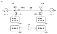
図1は、実施の形態1による故障点標定装置が設置された電力系統の構成図である。図1を参照して電力系統は、送電線102と、A端変電所において送電線102に接続された電流変成器(CT:Current Transformer)104_1および電圧変成器(VT:Voltage Transformer)105_1と、B端変電所において送電線102に接続されたCT104_2およびVT105_2と、送電線102の途中に接続された直列コンデンサ103とを備える。直列コンデンサの容量値をCとする。CT104_1,104_2の間の区間が送電線102の保護区間となっている。
[Schematic configuration of power system]
FIG. 1 is a configuration diagram of an electric power system in which the failure point locating device according to the first embodiment is installed. Referring to FIG. 1, a power system includes a
なお、電力系統は3相回路であるため、送電線102、直列コンデンサ103、ならびに各端子の変電所に設けられたCT104およびVT105は実際には3相分ある。図1では図解を容易にするために1相分のみを模式的に示している。
Since the power system is a three-phase circuit, the
送電線102のA端の遠方には3相の背後電源101_1が設けられ、送電線102のB端の遠方には3相の背後電源101_2が設けられている。背後電源101_1の各相の電圧振幅をEaとし、背後電源101_2の各相の電圧振幅をEbとする。
A three-phase back power supply 101_1 is provided far from the A end of the
さらに、電力系統は、A端変電所に設けられた故障点標定装置106_1と、B端変電所に設けられた故障点標定装置106_2と、通信装置108_1,108_2とを備える。各故障点標定装置106は、自端のCT104から電流値をサンプリングして取り込み、自端のVT105から電圧値をサンプリングして取り込む。各故障点標定装置106は、取り込んだ電流値および電圧値をA/D(Analog to Digital)変換することによって、デジタル値の電流データおよび電圧データを生成する。
Further, the power system includes a fault point locating device 106_1 provided at the A-end substation, a fault point locating device 106_2 provided at the B-end substation, and communication devices 108_1 and 108_2. Each fault
通信装置108_1,108,2は、自端の故障点標定装置106_1,106_2にそれぞれ接続される。各通信装置108は、自端の故障点標定装置106から電流データおよび電圧データの入力を受け、入力された自端の電流データおよび電圧データを相手端の通信装置108に伝送路107を介して送信する。各通信装置108は、伝送路107を介して受信した相手端の電流データおよび電圧データを自端の故障点標定装置106に出力する。
The communication devices 108_1, 108, 2 are connected to the fault point locating devices 106_1, 106_2 at their own ends, respectively. Each
各故障点標定装置106は、相手端の故障点標定装置106によってサンプリングされた電流データおよび電圧データを用いて同期処理を行う。そして、各故障点標定装置106は、伝送路107の伝送時間だけ自端のデータを遅延させることによって送電線102の両端でほぼ同時刻にサンプリングされた電圧データおよび電流データを得る。各故障点標定装置106は、これらの電圧データおよび電流データを用いて電流差動方式の保護リレー演算を行う。
Each fault
上記の同期処理の方法について補足する。具体的に、故障点標定装置106_1,106_2は、電流および電圧データを一定周期でシリアルデータとして送信することを通じて同期処理を行う。各故障点標定装置106に接続された通信装置108からの送信データには、電流および電圧データの他に、そのデータの送信タイミングを表すタイミング信号と、そのタイミング信号を送信してから相手端からのタイミング信号を受信するまでの時間差を表す信号が含まれる。各故障点標定装置106は、A端で測定した時間差TaとB端で測定した時間差Tbとが等しくなるようにどちらかの端子(例えばB端)で送信タイミングを調整することで同期を採ることができる。
A supplementary explanation will be given on the method of the above synchronization processing. Specifically, the fault point locating devices 106_1 and 106_2 perform synchronization processing by transmitting current and voltage data as serial data at a constant cycle. The transmission data from the
A端からB端への伝送遅延時間とB端からA端への伝送遅延時間が等しい場合には、上記の同期処理方法によって同期が採れる。しかしながら、両方向の伝送遅延時間に差がある場合には、(Ta−Tb)/2に相当する同期誤差が生じる。実際上の誤差の大きさは、汎用の通信装置で、最大250μ秒から500μ秒程度である。しかし、この程度の誤差であれば、電流差動リレーの動作特性を調整することによって保護動作上問題にならないようにできる。 When the transmission delay time from the A end to the B end is equal to the transmission delay time from the B end to the A end, synchronization is obtained by the above synchronization processing method. However, when there is a difference in the transmission delay time in both directions, a synchronization error corresponding to (Ta-Tb)/2 occurs. The practical size of the error is about 250 μsec to 500 μsec at the maximum in a general-purpose communication device. However, if the error is within this range, it is possible to prevent a problem in the protection operation by adjusting the operation characteristics of the current differential relay.
電流差動リレー以外の方法で保護区間での故障発生を検出する場合には同期処理は必要でない。この場合、片端、たとえば、A端の故障点標定装置106_1でのみ故障点標定を行う。B端の故障点標定装置106_2は、B端の電流および電圧を検出する機能と、A/D変換したB端の電流データおよび電圧データをA端の故障点標定装置106_1に送信する機能とを有していれば十分である。この場合、A端の故障点標定装置106_1は、A/D変換したA端の電流データおよび電圧データをB端の故障点標定装置106_2に送信する必要はない。 Synchronous processing is not necessary when a failure occurrence in the protection section is detected by a method other than the current differential relay. In this case, the fault point locating device 106_1 at one end, for example, the A end, performs fault point locating. The B-end fault point locator 106_2 has a function of detecting the B-end current and voltage and a function of transmitting A/D converted B-end current data and voltage data to the A-end fault point locator 106_1. It is enough to have. In this case, the A-point fault point locator 106_1 does not need to transmit the A/D converted current data and voltage data of the A-end to the B-point fault point locator 106_2.
ただし、電流差動リレー以外の方法で保護区間での故障発生を検出する場合においても、故障点標定を行うために、保護区間が故障中の際の両端での電流および電圧データは必要である。したがって、電流差動リレー演算に必要な精度でのサンプリング同期は必要ないとしても、ミリ秒オーダーでの同期は必要である。 However, even when a failure occurrence in the protection section is detected by a method other than the current differential relay, the current and voltage data at both ends when the protection section is in failure are necessary in order to locate the failure point. .. Therefore, even if the sampling synchronization with the accuracy required for the current differential relay calculation is not required, the synchronization in the millisecond order is necessary.
[故障点標定装置のハードウェア構成の一例]
図2は、図1の各故障点標定装置106のハードウェア構成の一例を示すブロック図である。図2の故障点標定装置106は、いわゆるデジタルリレー装置と同様の構成を有している。具体的に図2を参照して、故障点標定装置106は、入力変換部201と、A/D変換部211と、演算処理部221と、I/O(Input and Output)部231とを備える。
[Example of hardware configuration of fault location device]
FIG. 2 is a block diagram showing an example of the hardware configuration of each failure
入力変換部201は、各入力チャンネルごとに補助変成器202_1,202_2,…を備える。入力変換部201は、図1のCT104から出力された各相の電流信号および図1のVT105から出力された各相の電圧信号が入力される入力部である。各補助変成器202は、CT104およびVT105からの電流信号および電圧信号を演算処理部221および演算処理部221での信号処理に適した電圧レベルの信号に変換する。
The
A/D変換部211は、アナログフィルタ(AF:Analog Filter)212_1,212_2,…と、サンプルホールド回路(S/H:Sample Hold Circuit)213_1,213_2,…と、マルチプレクサ(MPX:Multiplexer)214と、A/D変換器215とを含む。アナログフィルタ212およびサンプルホールド回路213は、入力信号のチャンネルごとに設けられる。
The A/
各アナログフィルタ212は、A/D変換の際の折返し誤差を除去するために設けられたローパスフィルタである。各サンプルホールド回路213は、対応のアナログフィルタ212を通過した信号を規定のサンプリング周波数でサンプリングして保持する。サンプリング周波数は、たとえば、4800Hzである。マルチプレクサ214は、サンプルホールド回路213_1,213_2,…に保持された電圧信号を順次選択する。A/D変換器215は、マルチプレクサ214によって選択された信号をデジタル値に変換する。
Each
演算処理部221は、CPU(Central Processing Unit)222と、RAM(Random Access Memory)223と、ROM(Read Only Memory)224と、これらを接続するバス225とを含む。CPU222は、故障点標定装置106の全体の動作を制御する。RAM223およびROM224は、CPU222の主記憶として用いられる。ROM224は、フラッシュメモリなどの不揮発性メモリを用いることにより、プログラムおよび信号処理用の設定値などを収納することができる。
The
I/O部231は、自端の通信装置108と接続するためのインターフェース(I/F:Interface)回路232と、デジタル入力(D/I:Digital Input)回路234と、デジタル出力(D/O:Digital Output)回路235とを含む。デジタル入力回路234およびデジタル出力回路235は、CPU222と通信装置108以外の外部装置との間で通信を行う際のインターフェース回路である。
The I/
[故障点標定方法について]
以下、実施の形態1による故障点標定方法の原理について説明する。
[About fault location method]
Hereinafter, the principle of the fault location method according to the first embodiment will be described.
<1.簡易等価回路による表現>
図3は、直列コンデンサ103が送電線102の保護区間にある場合において故障点Fでa相地絡故障が生じた場合の回路図である。故障点抵抗をRとする。故障点抵抗はアーク抵抗である。図3では、直列コンデンサ103がA端と故障点Fとの間に存在している場合が示されている。
<1. Expression by simple equivalent circuit>
FIG. 3 is a circuit diagram when an a-phase ground fault occurs at the failure point F when the
図3において、A端変電所とB端変電所との間の送電線102の亘長を‘1’とした場合、A端変電所から故障点Fまでの距離の割合を‘X’とし、B端変電所から故障点Fまでの割合を‘1−X’とする。本実施の形態による故障点標定方法では、送電線102のA端およびB端の電流および電圧ならびに送電線102の線路定数を、対称座標法を用いて座標変換する。
In FIG. 3, when the length of the
図4は、図3の回路図に対応する対称座標法による等価回路である。図4に示すように、A端における正相電圧をVA1とし、B端における正相電圧をVB1とする。A端における正相電流をIA1とし、逆相電流をIA2とし、零相電流をIA0とする。B端における正相電流をIB1とし、逆相電流をIB2とし、零相電流をIB0とする。A端の背後電源101_1から出力される正相電圧をEAとし、B端の背後電源101_2から出力される正相電圧をEBとする。A端の背後電源101_1から故障点Fまでの送電線102の逆相インピーダンスをZA2とし、B端の背後電源101_2から故障点Fまでの送電線102の逆相インピーダンスをZB2とする。A端の背後電源101_1から故障点Fまでの送電線102の零相インピーダンスをZA0とし、B端の背後電源101_2から故障点Fまでの送電線102の零相インピーダンスをZB0とする。なお、逆相インピーダンスZA2には、直列コンデンサ103の逆相分のキャパシタンスが含まれる。零相インビーダンスZA0には、直列コンデンサ103の零相分のキャパシタンスが含まれる。
FIG. 4 is an equivalent circuit according to the symmetrical coordinate method corresponding to the circuit diagram of FIG. As shown in FIG. 4, the positive phase voltage at the A end is VA1 and the positive phase voltage at the B end is VB1. It is assumed that the positive-phase current at the A end is IA1, the negative-phase current is IA2, and the zero-phase current is IA0. The positive phase current at the B end is IB1, the negative phase current is IB2, and the zero phase current is IB0. The positive phase voltage output from the rear power supply 101_1 at the A terminal is EA, and the positive phase voltage output from the rear power supply 101_2 at the B terminal is EB. The anti-phase impedance of the
a相地絡故障の等価回路は、図4に示すように正相回路と逆相回路と零相回路とが故障点Fにおいて直列に接続された構成を有している。この場合、逆相回路、零相回路、および地絡点抵抗3・Rは、下式(1)のインピーダンスZFとして1つにまとめることができる。
The equivalent circuit of the a-phase ground fault has a configuration in which a positive-phase circuit, a negative-phase circuit, and a zero-phase circuit are connected in series at a fault point F, as shown in FIG. In this case, the anti-phase circuit, the zero-phase circuit, and the
ZF=ZA2//ZB2+ZA0//ZB0+3・R …(1)
上式(1)において、記号//は、並列接続のインピーダンスを表す。したがって、a相地絡故障の等価回路は、上式(1)のインピーダンスZFを用いることによって、図8(A)のように正相回路のみの簡易等価回路で表すことができる。なお、b相地絡故障およびc相地絡故障の場合も同様である。
ZF=ZA2//ZB2+ZA0/
In the above formula (1), the symbol // represents the impedance of parallel connection. Therefore, the equivalent circuit of the a-phase ground fault can be represented by a simple equivalent circuit of only the positive phase circuit as shown in FIG. 8A by using the impedance ZF of the above equation (1). The same applies to the b-phase ground fault and the c-phase ground fault.
図3および図4では1線地絡故障の場合の簡易等価回路について説明したが、他の故障種類である2線地絡故障、2線短絡故障、3相地絡故障、3相短絡故障の場合も同様の簡易等価回路で表すことができる。以下、図5〜図7を参照して簡単に説明する。 Although the simple equivalent circuit in the case of the 1-line ground fault has been described with reference to FIGS. 3 and 4, other types of the 2-line ground fault, 2-wire short-circuit fault, 3-phase ground fault, and 3-phase short-circuit fault are described. Even in the case, it can be represented by a similar simple equivalent circuit. Hereinafter, a brief description will be given with reference to FIGS.
図5は、図3の故障点Fにおいてbc相2線地絡故障が生じた場合の対称座標法による等価回路である。b相およびc相の単独の地絡点抵抗をrとし、共通の地絡点抵抗をRとする。図5に示すように、2線地絡故障の等価回路は、正相回路の故障点Fに逆相回路と零相回路とが並列に接続された構成を有する。したがって、下式(2)で表されるインピーダンスZF、すなわち、
ZF=r+(r+ZA2//ZB2)//(r+3R+ZA0//ZB0) …(2)
を用いることによって、bc相2線地絡故障の等価回路は、図8(A)の簡易等価回路で表すことができる。なお、ca相2線地絡故障およびab相2線地絡故障の場合も同様である。
FIG. 5 is an equivalent circuit based on the symmetric coordinate method when a
ZF=r+(r+ZA2//ZB2)//(r+3R+ZA0//ZB0) (2)
By using, the equivalent circuit of the bc-phase two-wire ground fault can be represented by the simple equivalent circuit of FIG. The same applies to the case of the
図6は、図3の故障点Fにおいてbc相2線短絡故障が生じた場合の対称座標法による等価回路である。図6に示すように、2線短絡故障の等価回路は、正相回路の故障点Fに逆相回路が並列に接続された構成を有する。したがって、下式(3)で表されるインピーダンスZF、すなわち、
ZF=ZA2//ZB2 …(3)
を用いることによって、bc相2線短絡故障の等価回路は、図8(A)の簡易等価回路で表すことができる。なお、ca相2線短絡故障およびab相2線短絡故障の場合も同様である。
FIG. 6 is an equivalent circuit based on the symmetric coordinate method when a
ZF=ZA2//ZB2 (3)
By using, the equivalent circuit of the bc-phase two-wire short-circuit fault can be represented by the simple equivalent circuit of FIG. The same applies to the case of a
図7は、図3の故障点Fにおいて3相地絡故障が生じた場合の正相回路である。なお、3相短絡故障の場合の正相回路は、図7において地絡点抵抗rが0になる。したがって、3相短絡故障および3相地絡故障の場合も、インピーダンスZFを用いることによって図8(A)の簡易等価回路で表すことができる。 FIG. 7 shows a positive-phase circuit in the case where a three-phase ground fault occurs at the fault point F in FIG. In the positive-phase circuit in the case of a three-phase short circuit failure, the ground fault resistance r becomes 0 in FIG. Therefore, even in the case of the three-phase short-circuit fault and the three-phase ground fault, the impedance ZF can be used to represent the simple equivalent circuit of FIG.
<2.故障点標定方法−直列コンデンサがA端と故障点Fとの間にある場合>
図8は、A端と故障点Fとの間に直列コンデンサ103が設けられている場合(すなわち、A端と直列コンデンサ103との間に故障点Fが存在せず、B端と直列コンデンサ103との間に故障点Fが存在する場合)において、正相回路による簡易等価回路と正相電圧の分布を示す図である。この明細書では、上記の場合のA端を第1端と称し、B端を第2端と称する場合がある。
<2. Fault Locating Method-When the series capacitor is located between the end A and the fault point F>
FIG. 8 shows a case where the
図8(A)に図3に対応する対称座標法による簡易等価回路が示される。上述のように、ほとんどすべての故障種類に対して図8(A)に示すように、正相回路の故障点FにインピーダンスZFを付加した簡易等価回路で電力系統を表すことができる。図8(A)において、「*」は乗算を表す記号である。 FIG. 8A shows a simple equivalent circuit according to the symmetrical coordinate method corresponding to FIG. As described above, the power system can be represented by a simple equivalent circuit in which the impedance ZF is added to the fault point F of the positive phase circuit as shown in FIG. 8A for almost all fault types. In FIG. 8A, “*” is a symbol representing multiplication.
図8(B)に図8(A)の簡易等価回路の各点における正相電圧の分布が示される。A端における正相電圧をVA1とし、正相電流をIA1とする。B端における正相電圧をVB1とし、正相電流をIB1とする。故障点Fにおける正相電圧をVFとする。 FIG. 8B shows the distribution of the positive phase voltage at each point in the simplified equivalent circuit of FIG. The positive phase voltage at the A terminal is VA1 and the positive phase current is IA1. The positive phase voltage at the B end is VB1 and the positive phase current is IB1. The positive phase voltage at the failure point F is VF.
図8(A)および図8(B)を参照して、A端からB端までの送電線102の亘長を1とし、A端から故障点Fまでの距離をXとし、B端から故障点Fまでの距離を1−Xとする。0≦X≦1が成り立つ。さらに、A端から直列コンデンサ103の設置位置までの距離をX1とし、直列コンデンサ103の設置位置から故障点Fまでの距離をX2とする。この場合、X=X1+X2が成り立つ。
8A and 8B, the length of the
さらに、A端からB端までの送電線102の亘長のインピーダンスをZとする。この場合、A端から故障点Fまでの直列コンデンサ103を含まないインピーダンスは、X*Zで表され、B端から故障点Fまでのインピーダンスは(1−X)*Zで表される。さらに、A端から直列コンデンサ103までの送電線102のインピーダンスはX1*Zであり、直列コンデンサ103から故障点Fまでの送電線102のインピーダンスはX2*Zである。
Further, the impedance of the length of the
図8(B)に示すように、直列コンデンサ103の設置点において正相電圧がVCだけ増加している。この正相電圧VCは、直列コンデンサ103のキャパシタンスCによる電圧増加である。直列コンデンサ103のインピーダンスZCは、虚数単位をjとし、系統周波数をfとして、
ZC=−j(1/ωC)、ω=2πf …(4)
で表される。したがって、直列コンデンサ103に電流IA1が流れるとその電圧VCは、
VC=ZC*IA1=−j(1/ωC)*IA1 …(5)
で表される。直列コンデンサ103の設置点ではこの電圧VCだけ正相電圧が増加する。
As shown in FIG. 8(B), the positive phase voltage increases by VC at the installation point of the
ZC=-j (1/ωC), ω=2πf (4)
It is represented by. Therefore, when the current IA1 flows through the
VC=ZC*IA1=-j(1/ωC)*IA1 (5)
It is represented by. At the installation point of the
ここで、A端の正相電圧VA1を上記の電圧VCによって補償した電圧VA1’、すなわち、
VA1’=VA1+VC …(6)
を考える。そうすると、故障点Fの正相電圧VFは、A端の補償電圧VA1’および正相電流IA1を用いて、
VF=VA1’−X*Z*IA1 …(7)
によって表される。
Here, a voltage VA1′ obtained by compensating the positive phase voltage VA1 at the A end with the above voltage VC, that is,
VA1'=VA1+VC (6)
think of. Then, the positive phase voltage VF at the fault point F is calculated by using the compensation voltage VA1′ at the A terminal and the positive phase current IA1.
VF=VA1'-X*Z*IA1 (7)
Represented by
また、故障点Fの正相電圧VFは、B端の正相電圧VB1および正相電流IB1を用いて、
VF=VB1−(1−X)*Z*IB1 …(8)
によって表される。
Further, the positive phase voltage VF at the fault point F is calculated by using the positive phase voltage VB1 at the B end and the positive phase current IB1.
VF=VB1-(1-X)*Z*IB1 (8)
Represented by
上記の(7)式および(8)式はそれぞれベクトル演算で成立するが、A端の電流および電圧データとB端の電流および電圧データとに同時刻性がないとすると、(7)式に従って計算された正相電圧VFと(8)式に従って計算された正相電圧VFとは、時間差があるために等しくならない。しかし、(7)式の正相電圧VFの振幅値と(8)式の正相電圧V故障点Fの振幅値とは、同時刻性は必要でないので、互いに等しくなる。 The above equations (7) and (8) are established by vector operations, respectively, but if the current and voltage data at the A terminal and the current and voltage data at the B terminal do not have the same time, then according to the equation (7), The calculated positive phase voltage VF and the positive phase voltage VF calculated according to the equation (8) are not equal to each other because of a time difference. However, since the amplitude value of the positive phase voltage VF of the expression (7) and the amplitude value of the positive phase voltage V failure point F of the expression (8) do not need the same time, they are equal to each other.
具体的に振幅値を記号「amp」で表すと、(7)式に対応する振幅値の関係式は、
VFamp=(VA1’−X*Z*IA1)amp …(9)
で表される。また、(8)式に対応する振幅値の関係式は、
VFamp=(VB1−(1−X)*Z*IB1)amp …(10)
で表される。したがって、
(VA1’−X*Z*IA1)amp=(VB1−(1-X)*Z*IB1)amp …(11)
が成立する。ここで、(11)式は、X以外は全て既知であるのでXを算出することができる。A端とB端との間の送電線102の実際の亘長を、算出したXに乗算することによって、A端から故障点Fまでの距離を計算することができる。
Specifically, when the amplitude value is represented by the symbol “amp”, the relational expression of the amplitude value corresponding to the expression (7) is
VFamp=(VA1'-X*Z*IA1) amp (9)
It is represented by. Further, the relational expression of the amplitude value corresponding to the expression (8) is
VFamp=(VB1-(1-X)*Z*IB1) amp (10)
It is represented by. Therefore,
(VA1'-X*Z*IA1) amp = (VB1--(1-X)*Z*IB1) amp …(11)
Is established. Here, since all the equations (11) except X are known, X can be calculated. The distance from the A end to the failure point F can be calculated by multiplying the calculated X by the actual length of the
なお、(11)式において、時系列にサンプリングされたデータを用いて振幅値を演算する方法は、公知の方法を用いることができる。たとえば、大浦好文監修、「保護リレーシステム工学」、初版、社団法人電気学会、2002年3月、p.111(非特許文献1)の表5.2に記載された各種の振幅値演算方法を適用することができる(これに限定されるものではない)。 In the equation (11), a known method can be used as the method of calculating the amplitude value using the data sampled in time series. For example, Yoshifumi Oura, "Protective Relay System Engineering", First Edition, The Institute of Electrical Engineers of Japan, March 2002, p. Various amplitude value calculation methods described in Table 5.2 of 111 (Non-Patent Document 1) can be applied (but not limited to this).
<3.故障点標定方法−直列コンデンサがB端と故障点Fとの間にある場合>
図9は、B端と故障点Fとの間に直列コンデンサ103が設けられている場合(すなわち、A端と直列コンデンサ103との間に故障点Fが存在し、B端と直列コンデンサ103との間に故障点Fが存在しない)において、簡易等価回路と正相電圧の分布を示す図である。この明細書では、上記の場合のB端を第1端と称し、A端を第2端と称する場合がある。
<3. Fault Locating Method-When the series capacitor is located between the end B and the fault point F>
9 shows a case where the
ほとんどすべての故障種類に対して図9(A)に示すように、正相回路の故障点FにインピーダンスZFを付加した簡易等価回路で電力系統を表すことができる。図9(B)に図9(A)の簡易等価回路の各点における正相電圧の分布が示される。 As shown in FIG. 9A for almost all types of failure, the power system can be represented by a simple equivalent circuit in which the impedance ZF is added to the failure point F of the positive phase circuit. FIG. 9B shows the distribution of the positive phase voltage at each point of the simple equivalent circuit of FIG. 9A.
図9(A)および図9(B)を参照して、A端からB端までの送電線102の亘長を1とし、A端から故障点Fまでの距離をXとし、B端から故障点Fまでの距離を1−Xとする。0≦X≦1が成り立つ。さらに、B端から直列コンデンサ103の設置位置までの距離をX1とし、直列コンデンサ103の設置位置から故障点Fまでの距離をX2とする。この場合、1−X=X1+X2が成り立つ。
With reference to FIGS. 9A and 9B, the length of the
直列コンデンサ103に電流IB1が流れると、直列コンデンサ103に生じる電圧VCは、
VC=ZC*IB1=−j(1/ωC)*IB1 …(12)
で表される。直列コンデンサ103の設置点ではこの電圧VCだけ正相電圧が増加する。
When the current IB1 flows through the
VC=ZC*IB1=-j(1/ωC)*IB1 (12)
It is represented by. At the installation point of the
ここで、B端の正相電圧VB1を上記の電圧VCによって補償した電圧VB1’、すなわち、
VB1’=VB1+VC …(13)
を考える。そうすると、故障点Fの正相電圧VFは、B端の補償電圧VB1’および正相電流IB1を用いて、
VF=VB1’−(1−X)*Z*IB1 …(14)
によって表される。
Here, a voltage VB1′ obtained by compensating the positive phase voltage VB1 at the B end with the above voltage VC, that is,
VB1'=VB1+VC (13)
think of. Then, the positive phase voltage VF at the failure point F is calculated by using the compensation voltage VB1′ at the B end and the positive phase current IB1.
VF=VB1'-(1-X)*Z*IB1 (14)
Represented by
また、故障点Fの正相電圧VFは、A端の正相電圧VA1および正相電流IA1を用いて、
VF=VA1−(1−X)*Z*IA1 …(15)
によって表される。
The positive phase voltage VF at the fault point F is calculated by using the positive phase voltage VA1 at the A terminal and the positive phase current IA1.
VF=VA1-(1-X)*Z*IA1 (15)
Represented by
A端の電流および電圧データとB端の電流および電圧データとの間での同時刻性を不要とするために、上式(14)および(15)の振幅値演算を行うと、
VFamp=(VB1’−(1−X)*Z*IB1)amp …(16)
VFamp=(VA1−(1−X)*Z*IA1)amp …(17)
が成立する。したがって、
(VA1−X*Z*IA1)amp=(VB1'−(1-X)*Z*IB1)amp …(18)
が成立する。ここで、(18)式は、X以外は全て既知であるのでXを算出することができる。A端とB端との間の送電線102の実際の亘長を、算出したXに乗算することによって、A端から故障点Fまでの距離を計算することができる。
In order to eliminate the need for simultaneity between the current and voltage data at the A terminal and the current and voltage data at the B terminal, the amplitude value calculation of the above equations (14) and (15) is performed.
VFamp=(VB1'-(1-X)*Z*IB1) amp (16)
VFamp=(VA1-(1-X)*Z*IA1) amp (17)
Is established. Therefore,
(VA1−X*Z*IA1) amp=(VB1′−(1-X)*Z*IB1) amp …(18)
Is established. Here, since all the equations (18) except X are known, X can be calculated. The distance from the A end to the failure point F can be calculated by multiplying the calculated X by the actual length of the
<4.直列コンデンサの設置位置と故障点Fとの関係>
次に、故障点FがA端と直列コンデンサ103との間に存在するか、B端と直列コンデンサ103との間に存在するかを簡単に判定する方法について説明する。
<4. Relationship between installation position of series capacitor and failure point F>
Next, a method of simply determining whether the fault point F exists between the A terminal and the
図10は、図8(A)の簡易等価回路におけるインピーダンス図である。図10(A)にA端から見たインピーダンス図を示し、図10(B)にB端から見たインピーダンス図を示す。 FIG. 10 is an impedance diagram in the simple equivalent circuit of FIG. FIG. 10A shows an impedance diagram seen from the A end, and FIG. 10B shows an impedance diagram seen from the B end.
図8(A)および図10(A)を参照して、A端の正相電圧VA1および正相電流IA1を用いて計算したインピーダンスをVA1/IA1とし、その位相角をφAとする。インピーダンスVA1/IA1は、A端から直列コンデンサ103までの送電線102のインピーダンスX1*Zと、直列コンデンサ103のインピーダンスZCと、直列コンデンサ103から故障点Fまでの送電線102のインピーダンスX2*Zと、故障点FのインピーダンスZFとを合成(すなわち、ベクトル加算)した値に等しい。
With reference to FIGS. 8A and 10A, the impedance calculated using the positive phase voltage VA1 and the positive phase current IA1 at the A end is VA1/IA1, and the phase angle is φA. The impedance VA1/IA1 is the impedance X1*Z of the
図8(A)および図10(B)を参照して、B端の正相電圧VB1および正相電流IB1を用いて計算したインピーダンスをVB1/IB1とし、その位相角をφBとする。インピーダンスVB1/IB1は、B端から故障点Fまでの送電線102のインピーダンス(1−X)*Zと、故障点FのインピーダンスZFとを合成した値に等しい。
With reference to FIGS. 8A and 10B, the impedance calculated using positive phase voltage VB1 and positive phase current IB1 at the B end is VB1/IB1 and its phase angle is φB. The impedance VB1/IB1 is equal to a value obtained by combining the impedance (1-X)*Z of the
図10(A)と図10(B)とを比較すると、直列コンデンサ103のインピーダンスZC=−j(1/ωC)のため、A端から見たインピーダンスVA1/IA1の位相角φAは、B端から見たインピーダンスVB1/IB1の位相角φBよりも明らかに小さい。すなわち、φA<φBとなる。
Comparing FIG. 10A and FIG. 10B, because the impedance ZC=−j(1/ωC) of the
図11は、図9(A)の簡易等価回路におけるインピーダンス図である。図11(A)にA端から見たインピーダンス図を示し、図11(B)にB端から見たインピーダンス図を示す。 FIG. 11 is an impedance diagram in the simple equivalent circuit of FIG. FIG. 11A shows an impedance diagram seen from the A end, and FIG. 11B shows an impedance diagram seen from the B end.
図9(A)および図11(A)を参照して、A端の正相電圧VA1および正相電流IA1を用いて計算したインピーダンスをVA1/IA1とし、その位相角をφAとする。インピーダンスVA1/IA1は、A端から故障点Fまでの送電線102のインピーダンスX*Zと、故障点FのインピーダンスZFとを合成した値に等しい。
With reference to FIGS. 9A and 11A, the impedance calculated using the positive phase voltage VA1 and the positive phase current IA1 at the A end is VA1/IA1 and the phase angle is φA. The impedance VA1/IA1 is equal to a value obtained by combining the impedance X*Z of the
図9(A)および図11(B)を参照して、B端の正相電圧VB1および正相電流IB1を用いて計算したインピーダンスをVB1/IB1とし、その位相角をφBとする。インピーダンスVB1/IB1は、B端から直列コンデンサ103までの送電線102のインピーダンスX1*Zと、直列コンデンサ103のインピーダンスZCと、直列コンデンサ103から故障点Fまでの送電線102のインピーダンスX2*Zと、故障点FのインピーダンスZFとを合成(すなわち、ベクトル加算)した値に等しい。
With reference to FIGS. 9A and 11B, the impedance calculated using positive phase voltage VB1 and positive phase current IB1 at the B end is VB1/IB1 and its phase angle is φB. The impedance VB1/IB1 is the impedance X1*Z of the
図11(A)と図11(B)とを比較すると、直列コンデンサ103のインピーダンスZC=−j(1/ωC)のため、A端から見たインピーダンスVA1/IA1の位相角φAは、B端から見たインピーダンスVB1/IB1の位相角φBよりも明らかに大きい。すなわち、φA>φBとなる。
Comparing FIG. 11A and FIG. 11B, since the impedance ZC=−j(1/ωC) of the
以上により、A端から見たインピーダンスVA1/IA1の位相角φAと、B端から見たインピーダンスVB1/IB1の位相角φBとを比較し、φA<φBの場合には、故障点FはB端と直列コンデンサ103との間に存在し、A端と直列コンデンサ103との間には存在しないと判定することができる。一方、φA>φBの場合には、故障点FはA端と直列コンデンサ103との間に存在し、B端と直列コンデンサ103との間には存在しないと判定することができる。
From the above, the phase angle φA of the impedance VA1/IA1 seen from the A end is compared with the phase angle φB of the impedance VB1/IB1 seen from the B end. When φA<φB, the failure point F is the B end. Can be determined to exist between the end A and the
そして、故障点FがB端と直列コンデンサ103との間に存在すると判定された場合には、前述の(5)式および(6)式に従ってA端の正相電圧を補償し、前述の(11)式に従って未知数Xを計算することができる。一方、故障点FがA端と直列コンデンサ103との間に存在すると判定された場合には、前述の(12)式および(13)式に従ってB端の正相電圧を補償し、前述の(18)式に従って未知数Xを計算することができる。
When it is determined that the fault point F exists between the B end and the
[故障点標定の具体的手順]
以下、これまでの説明を総括して、故障低標定の具体的手順について説明する。
[Specific procedure for fault location]
In the following, a specific procedure for fault low localization will be described by summarizing the above description.
図12は、実施の形態1の故障点標定装置の機能ブロック図である。図13は、実施の形態1の故障点標定手順を示すフローチャートである。図14は、図13のステップS104の手順をさらに詳しく示すフローチャートである。 FIG. 12 is a functional block diagram of the fault point locating device according to the first embodiment. FIG. 13 is a flowchart showing a fault point locating procedure according to the first embodiment. FIG. 14 is a flowchart showing the procedure of step S104 of FIG. 13 in more detail.
図12を参照して、故障点標定装置106は、機能的に見ると、電流・電圧データ入出力部120と、同期処理部121と、第1の記憶領域RAM1と、第2の記憶領域RAM2と、送電線故障検出部122と、座標変換部123と、故障区間判定部124と、端子電圧補償部125と、故障点判定部126とを含む。
With reference to FIG. 12, the failure
電流・電圧データ入出力部120は、図2の入力変換部201ならびに通信装置108に接続されたI/O部231のインターフェース回路232に対応する。第1の記憶領域RAM1および第2の記憶領域RAM2は、図2の演算処理部221のRAM223に設けられた記憶領域である。同期処理部121、送電線故障検出部122、座標変換部123、故障区間判定部124、端子電圧補償部125、および故障点判定部126の各機能は、図2の演算処理部221のCPU222によってプログラムが実行されることによって実現される。なお、図2のCPU222に代えて、FPGA(Field Programmable Gate Array)またはASIC(Application Specific Integrated Circuit)などによって構成した専用回路によっても、これらの機能を実現することができる。以下、図12の故障点標定装置106の各構成要素の動作について、図13および図14のフローチャートに沿って説明する。
The current/voltage data input/
図12および図13を参照して、ステップS100において、電流・電圧データ入出力部120(具体的には、入力変換部201)は、CT104から自端の電流値の入力を受け、VT105から自端の電圧値の入力を受ける。図2のA/D変換部211は、入力された電流値および電圧値を規定のサンプリング周波数(たとえば、4800Hz)でサンプリングし、サンプリングした電流値および電圧値をデジタル値にA/D変換する。
Referring to FIGS. 12 and 13, in step S100, current/voltage data input/output unit 120 (specifically, input conversion unit 201) receives the current value of its own end from
次のステップS101において、電流・電圧データ入出力部120(具体的には、図2の通信装置108に接続されたインターフェース回路232)は、A/D変換後の電流データおよび電圧データを、伝送路107および通信装置108_1,108_2を介して相手端の故障点標定装置106に送信する。また、ステップS102において、電流・電圧データ入出力部120(具体的には、図2の通信装置108に接続されたインターフェース回路232)は、相手端の故障点標定装置106によってサンプリングされた相手端の電流データおよび電圧データを受信する。
In the next step S101, the current/voltage data input/output unit 120 (specifically, the
次のステップS103において、各故障点標定装置106の同期処理部121は、自端の電流データおよび電圧データに対して同期処理を行う。具体的に、各故障点標定装置106は、自端から他端への伝送路107の伝送時間と他端から自端への伝送路107の伝送時間が等しいとして、伝送路107の伝送遅延時間(通常は、数m秒)だけ自端の電流データおよび電圧データのサンプリング時刻を遅らせることにより、自端のデータのサンプリング時刻と他端のデータのサンプリング時刻とをほぼ同時刻にする。
In the next step S103, the
次のステップS104において、送電線故障検出部122は、電流差動方式などによる保護リレー演算を行うことによって送電線102の保護区間(本実施形態の場合、A端とB端との間)における故障の有無を検出するとともに、電流データおよび電圧データの急変を検出する。
In the next step S104, the power transmission line
図14は、図13のステップS104の手順をさらに詳しく示すフローチャートである。図15は、第2の記憶領域RAM2のデータ保存期間を説明するためのタイミング図である。 FIG. 14 is a flowchart showing the procedure of step S104 of FIG. 13 in more detail. FIG. 15 is a timing chart for explaining the data storage period of the second storage area RAM2.
図12、図14および図15を参照して、ステップS200において、第1の記憶領域RAM1および第2の記憶領域RAM2は、同期処理後の自端および他端の電流データおよび電圧データの入力を受ける。 12, 14, and 15, in step S200, first storage area RAM1 and second storage area RAM2 receive current data and voltage data of their own ends and the other end after synchronization processing. receive.
次のステップS201において、第1の記憶領域RAM1および第2の記憶領域RAM2は、最新の自端の電流データおよび電圧データと最新の他端の電流データおよび電圧データとを格納する。このとき、第1の記憶領域RAM1および第2の記憶領域RAM2の格納データは、電流・電圧データ入出力部120によって最新のデータが取得される度に、その最新のデータが最も古いデータに置換されることによって更新される。第1の記憶領域RAM1のデータ格納期間は、電流差動リレーなどの保護リレー演算に必要な期間である。第2の記憶領域RAM2のデータ格納期間は、故障点標定に必要な期間であり、図15のT1期間である。
In the next step S201, the first storage area RAM1 and the second storage area RAM2 store the latest current data and voltage data of its own end and the latest current data and voltage data of the other end. At this time, the stored data in the first storage area RAM1 and the second storage area RAM2 are replaced with the oldest data each time the latest data is acquired by the current/voltage data input/
次のステップS202において、送電線故障検出部122は、自端(または他端)の電流データまたは電圧データが急変したか否かを検出する。この急変検出処理として、たとえば、現時点のデータと1サイクル前のデータとの差が閾値を超えているか、または、現時点のデータと半サイクル前のデータとの和が閾値を超えているかが検出される。このような処理は、一般に電流(または電圧)変化幅リレーと称され、電流差動リレーなどの保護リレー演算よりも早く異常を検出することができる。
In the next step S202, the power transmission line
この結果、電流データまたは電圧データの急変が検出された場合には(ステップS202でYES)、次のステップS205において第2の記憶領域RAM2は、その急変検出時刻t2からT2期間(T2はT1よりも小さい)の経過後にデータの更新を停止する。これによって、電流データまたは電圧データの急変が検出された時刻t2前後のT1期間(図15の時刻t1から時刻t4まで)のデータが、第2の記憶領域RAM2に保存される(図13のステップS105)。第2の記憶領域RAM2に保存されたデータは、図13のステップS106以降の故障点標定に用いられる。なお、故障点標定後に、第2の記憶領域RAM2に格納されるデータの更新が再開される。 As a result, when a sudden change in the current data or the voltage data is detected (YES in step S202), the second storage area RAM2 in the next step S205 has a T2 period (T2 is longer than T1) from the sudden change detection time t2. (Small) also stops updating the data. As a result, the data in the T1 period (from time t1 to time t4 in FIG. 15) before and after time t2 when the sudden change in the current data or the voltage data is detected is stored in the second storage area RAM2 (step in FIG. 13). S105). The data stored in the second storage area RAM2 is used for fault point localization after step S106 in FIG. After the fault point is located, the update of the data stored in the second storage area RAM2 is restarted.
このステップS202と並行して、ステップS203において送電線故障検出部122は、電流差動方式などによる保護リレー演算を行い、これにより送電線102の保護区間(本実施形態の場合、A端とB端との間)における故障の有無を検出する。この結果、保護区間内で送電線102の故障が検出された場合には(ステップS204でYES)、次のステップS106以降に処理が進み、故障点標定が実行される。
In parallel with this step S202, in step S203, the power transmission line
一方、電流または電圧の急変が検出された時刻t2からT3期間が経過しても送電線102の保護区間内での故障が検出されなかった場合には(ステップS204でNO)、ステップS105で第2の記憶領域RAM2に保存されたデータは無効とされ、第2の記憶領域RAM2に格納されるデータの更新が再開される。
On the other hand, if a failure in the protection section of the
図15において、一般的な時間設定例として、T1期間は2から3サイクルに設定され、T2期間は1から2サイクル程度に設定され、T3期間は3サイクル以上に設定される(これらの設定値に限定されるものではない)。 In FIG. 15, as a general time setting example, the T1 period is set to 2 to 3 cycles, the T2 period is set to about 1 to 2 cycles, and the T3 period is set to 3 cycles or more (these setting values are set). Is not limited to).
再び図12および図13を参照して、次のステップS106において、座標変換部123は、第2の記憶領域RAM2に格納されたT1期間のデータのうち、故障区間に相当する期間のうち振幅値演算に必要な1サイクル程度のデータを取り出す。第2の記憶領域RAM2に格納されたデータには、遮断器開放、つまり、故障除去後のデータが含まれている可能性があり、そのデータは故障点標定に用いることができないからである。座標変換部123は、取り出したA端のa相電圧Va、b相電圧Vb、c相電圧Vcの時系列データを用いてA端の正相電圧VA1の時系列データを算出する。同様に、座標変換部123は、A端のa相電流Ia、b相電流Ib、c相電流Icの時系列データを用いてA端の正相電流IA1の時系列データを算出する。さらに、座標変換部123は、B端のa相電圧Va、b相電圧Vb、c相電圧Vcの時系列データを用いてB端の正相電圧VB1の時系列データを算出し、B端のa相電流Ia、b相電流Ib、c相電流Icの時系列データを用いてB端の正相電流IB1の時系列データを算出する。
Referring again to FIG. 12 and FIG. 13, in the next step S106, the coordinate
以下、A端およびB端の正相電圧を総称してV1と記載し、A端およびB端の正相電流を総称してI1と記載する。正相電圧V1および正相電流I1は、次の(19)式および(20)式に従って計算される。 Hereinafter, the positive phase voltages at the A terminal and the B terminal will be collectively referred to as V1, and the positive phase currents at the A terminal and the B terminal will be collectively referred to as I1. The positive phase voltage V1 and the positive phase current I1 are calculated according to the following equations (19) and (20).
V1=(Va+a*Vb+(a^2)*Vc)/3 …(19)
I1=(Ia+a*Ib+(a^2)*Ic)/3 …(20)
ここで、「^」は累乗を表す記号であり、aは120°の移相を表し、
a=(1−j√3)/2 …(21)
によって定義される。したがって、a^2は240°の移相を表す。
V1=(Va+a*Vb+(a^2)*Vc)/3 (19)
I1=(Ia+a*Ib+(a^2)*Ic)/3 (20)
Here, “^” is a symbol representing a power, a represents a phase shift of 120°,
a=(1-j√3)/2 (21)
Defined by Therefore, a^2 represents a 240° phase shift.
図16は、120°および240°の移相演算方法について説明するための図である。図16を参照して、120°および240°の移相演算にはサンプリングデータの電気角で例えば60°前のデータを使って計算することができる。 FIG. 16 is a diagram for explaining a phase shift calculation method for 120° and 240°. Referring to FIG. 16, the phase shift operation of 120° and 240° can be calculated by using the electrical angle of the sampling data, for example, 60° before.
具体的に、図16において、現時点の電圧データをV(t)とし、現時点よりも電気角60°前の電圧データをV(t−60°)とする。そうすると、現時点の電圧データV(t)を120°移相した電圧データV∠120°および240°移相した電圧データV∠240°は、
V∠120°=−V(t−60°) …(22)
V∠240°=V(t−60°)−V(t) …(23)
で表される。
Specifically, in FIG. 16, voltage data at the current time point is V(t), and voltage data at an electrical angle of 60° before the current time point is V(t-60°). Then, the voltage data V∠120° obtained by phase-shifting the current voltage data V(t) by 120° and the voltage data V∠240° obtained by phase-shifting 240° are
V∠120°=−V(t−60°) (22)
V∠240°=V(t−60°)−V(t) (23)
It is represented by.
したがって、(19)式のa*Vbおよび(a^2)*Vcは、
a*Vb=Vb∠120°=−Vb(t−60°) …(24)
(a^2)*Vc=Vc∠240°=Vc(t−60°)−Vc(t) …(25)
に従って、計算することができる。正相電流I1の場合も同様である。
Therefore, a*Vb and (a^2)*Vc in equation (19) are
a*Vb=Vb∠120°=−Vb(t−60°) (24)
(A^2)*Vc=Vc∠240°=Vc(t−60°)−Vc(t) (25)
Can be calculated according to. The same applies to the case of the positive phase current I1.
次のステップS107において、故障区間判定部124は、A端から見た送電線102のインピーダンスVA1/IA1の位相角φA=Arg(VA1/IA1)と、B端から見た送電線102のインピーダンスVB2/IB2の位相角φB=Arg(VB2/IB2)とを算出する。
In the next step S107, the failure
次にステップS108において、故障区間判定部124は、位相角φAおよびφBの大小を判定する。故障区間判定部124は、φA<φBの場合には、故障点FはB端と直列コンデンサ103との間にあると判定する(ステップS109)。この場合、端子電圧補償部125は、前述の(5)式および(6)式に従ってA端の正相電圧VA1を補償した補償電圧VA1’を算出し、故障点判定部126は、前述の(11)式の未知数Xを求める。算出したXに送電線102の実際の亘長を乗算することによって、A端から故障点Fまでの距離が標定できる。
Next, in step S108, the failure
一方、故障区間判定部124は、φA>φBの場合には、故障点FはA端の直列コンデンサ103との間にあると判定する(ステップS111)。この場合、端子電圧補償部125は、前述の(12)式および(13)式に従ってB端の正相電圧VB1を補償した補償電圧VB1’を算出し、故障点判定部126は、前述の(18)式の未知数Xを求める。算出したXに送電線102の実際の亘長を乗算することによって、A端から故障点Fまでの距離が標定できる。
On the other hand, when φA>φB, the failure
故障区間判定部124は、φA=φBの場合には、故障点Fは直列コンデンサ103の配置位置であると判定して(ステップS113)、処理を終了する。もしくは、φA=φBの場合には、判定不可として(11)式および(18)式の双方で未知数Xを求めることによって、A端から故障点Fまでの距離とB端から故障点Fまでの距離とを参考値として表示するようにしてもよい。
When φA=φB, the failure
[変形例]
図13のステップS101およびステップS102において、故障点標定装置106_1,106_2は、3相電流および3相電圧を、伝送路107を介して相互にやり取りするようにしている。これに代えて、各故障点標定装置106においてまず正相電流および正相電圧に座標変換し、相手端の故障点標定装置106に正相電圧および正相電流を送信するようにしてもよい。これによって、伝送路107を介して伝送するデータ量を少なくすることができるとともに、第1の記憶領域RAM1および第2の記憶領域RAM2に格納するデータ量を少なくすることができる。
[Modification]
In steps S101 and S102 of FIG. 13, the fault point locating devices 106_1 and 106_2 mutually exchange the three-phase current and the three-phase voltage via the
図14のステップS202では、同期処理前の自端の電流データまたは電圧データをそのまま用いて電流または電圧が急変したか否かを判定するようにしてもよい。同期処理を行わないので、より早く電流または電圧の急変を検出できる。 In step S202 of FIG. 14, the current data or the voltage data of the self end before the synchronization processing may be used as it is to determine whether or not the current or the voltage suddenly changes. Since the synchronization process is not performed, a sudden change in current or voltage can be detected earlier.
図13のステップS103の同期処理は、送電線102の故障検出に電流差動方式を用いるために行っている。したがって、他の方式によって送電線102の故障検出を行う場合には同じ故障状態のデータのやりとりができればよく、正確な同期処理の必要はない。
The synchronization processing in step S103 of FIG. 13 is performed because the current differential method is used for detecting the failure of the
図17は、故障点標定装置を備えた電力系統の他の構成例を示す図である。図17の電力系統は、図1の故障点標定装置106_1,106_2に代えて電流差動方式の保護リレー装置110_1,110_2が設けられる。故障点標定装置111は、各保護リレー装置から検出された電流データおよび電圧データを受信する。
FIG. 17: is a figure which shows the other structural example of the electric power system provided with the fault location device. The electric power system of FIG. 17 is provided with current differential type protection relay devices 110_1 and 110_2 in place of the fault point locating devices 106_1 and 106_2 of FIG. The fault
この場合、故障点標定装置111は、ハードウェア構成として、図2の演算処理部221と、I/O部231のデジタル入力回路234およびデジタル出力回路235とを備える。図13のステップS105までは各保護リレー装置110および通信装置108によって実行され、故障点標定装置111は、図13のステップS106以降の各ステップを実行するように構成される。
In this case, the fault
[効果]
上記のとおり、実施の形態1の故障点標定装置106,111は、直列コンデンサ103を有する送電線102の故障点標定に好適に用いられる。
[effect]
As described above, the fault
具体的に、故障点標定装置106,111は、A端の正相電圧および正相電流から得られるインピーダンス角φAとB端の正相電圧および正相電流から得られるインピーダンス角φBとを比較することによって、故障点Fが直列コンデンサ103よりもA端の近くにあるか、B端の近くにあるかをまず判定する。そして、故障点Fが直列コンデンサ103よりもB端の近くにある場合には、直列コンデンサ電圧によってA端の正相電圧を補償し、A端の補償電圧とA端の正相電流とを用いて故障点Fの正相電圧VFを演算する。さらに、B端の正相電圧とB端の正相電流とを用いて故障点Fの正相電圧VFを演算する。これらの2通りの演算による正相電圧VFの振幅値が等しいとして、A端およびB端から故障点までの距離が求められる。故障点Fが直列コンデンサ103よりもA端の近くにある場合にも同様の計算によって故障点を標定することができる。
Specifically, the
このように、実施の形態1の故障点標定方法では、A端の電圧および電流とB端の電圧および電流とを合成(ベクトル演算)する必要がないので、両端のデータの正確なサンプリング同期は不要である。したがって、GPSを用いた高精度の同期処理を行わなくても、精度のよい故障点標定を行うことができる。さらに、実施の形態1の故障点標定方法は、故障種類によらず同一の演算式を用いることができるというメリットがある。 As described above, in the fault point locating method according to the first embodiment, it is not necessary to combine (vector operation) the voltage and current at the A terminal and the voltage and current at the B terminal, so that accurate sampling synchronization of the data at both ends is achieved. It is unnecessary. Therefore, accurate fault location can be performed without performing highly accurate synchronization processing using GPS. Further, the fault point locating method of the first embodiment has an advantage that the same arithmetic expression can be used regardless of the fault type.
実施の形態2.
実施の形態2では、図1の直列コンデンサ103に保護回路が設けられている場合について説明する。以下では、保護回路として、金属酸化物バリスタ(MOV:Metal Oxide Varistor)を例に挙げて説明する。
In the second embodiment, a case where the
図18は、保護回路MOVが並列接続された直列コンデンサSCを示す回路図と、保護回路MOVの電圧電流特性とを示す図である。図18(A)に回路図が示される。直列コンデンサSCと保護回路MOVとの並列回路に印加される電圧をVVとし、並列回路に流れる電流をIVとする。図18(B)に保護回路MOVの電圧vMOVと電流iMOVとの関係が示される。図18(B)に示すように電流iMOVが増加しても保護回路MOVに生じる電圧vMOVが制限されるために、図18(A)の電圧VVも制限される。これによって、直列コンデンサSCにかかる電圧が定格電圧を超えないように保護することができる。 FIG. 18 is a circuit diagram showing a series capacitor SC in which the protection circuit MOV is connected in parallel and a voltage-current characteristic of the protection circuit MOV. A circuit diagram is shown in FIG. The voltage applied to the parallel circuit of the series capacitor SC and the protection circuit MOV is V V, and the current flowing in the parallel circuit is I V. FIG. 18B shows the relationship between the voltage v MOV of the protection circuit MOV and the current i MOV . As shown in FIG. 18B, since the voltage v MOV generated in the protection circuit MOV is limited even if the current i MOV increases, the voltage V V in FIG. 18A is also limited. This makes it possible to protect the voltage applied to the series capacitor SC from exceeding the rated voltage.
図19は、図18(A)に示す回路の等価回路とその特性を示す図である。図18(A)に示す直列コンデンサSCと保護回路MOVとの並列接続回路は、図19(A)において抵抗RVとリアクタンスXVとの直列回路として示されている。図19(B)には、電流のIVの絶対値|IV|に対する保護回路付き直列コンデンサSCのインピーダンス特性(すなわち、抵抗RVおよびリアクタンスXVの特性)が示されている。 FIG. 19 is a diagram showing an equivalent circuit of the circuit shown in FIG. 18A and its characteristics. The parallel connection circuit of the series capacitor SC and the protection circuit MOV shown in FIG. 18A is shown as a series circuit of the resistor R V and the reactance X V in FIG. 19A. FIG. 19B shows the impedance characteristic (that is, the characteristic of the resistance R V and the reactance X V ) of the series capacitor SC with the protection circuit with respect to the absolute value |I V | of the current I V.
図19(B)に示すように、保護回路MOVを有する直列コンデンサSCは、電流に応じてインピーダンス(すなわち、抵抗およびリアクタンス)が変化する素子として特徴付けることができる。そこで、電流に対する抵抗およびリアクタンス特性をメモリに記憶することによって、図8および図9に示す直列コンデンサに生じる電圧VCを計算することができる。 As shown in FIG. 19B, the series capacitor SC having the protection circuit MOV can be characterized as an element whose impedance (that is, resistance and reactance) changes according to the current. Therefore, by storing the resistance and reactance characteristics with respect to the current in the memory, the voltage VC generated in the series capacitor shown in FIGS. 8 and 9 can be calculated.
具体的に、a相送電線に接続された保護回路付き直列コンデンサの抵抗をRvaとし、リアクタンスをXvaとする。b相送電線に接続された保護回路付き直列コンデンサの抵抗をRvbとし、リアクタンスをXvbとする。c相送電線に接続された保護回路付き直列コンデンサの抵抗をRvcとし、リアクタンスをXvcとする。この場合、保護回路付き直列コンデンサに生じる電圧VCは、前述の式(21)のa=(1−j√3)/2、a相電流Ia、b相電流Ib、およびc相電流Icを用いて、
VC=((Xva+Rva)*Ia+a*(Xvb+Rvb)*Ib+(a^2)*(Xvc+Rvc)*Ic) …(26)
で表される。上式(26)は、前述の(5)式または(12)式に代えて用いられる。
Specifically, the resistance of the series capacitor with the protection circuit connected to the a-phase power transmission line is Rva, and the reactance is Xva. The resistance of the series capacitor with the protection circuit connected to the b-phase transmission line is Rvb, and the reactance is Xvb. The resistance of the series capacitor with the protection circuit connected to the c-phase power transmission line is Rvc, and the reactance is Xvc. In this case, as the voltage VC generated in the series capacitor with the protection circuit, a=(1−j√3)/2, the a phase current Ia, the b phase current Ib, and the c phase current Ic in the above equation (21) are used. hand,
VC=((Xva+Rva)*Ia+a*(Xvb+Rvb)*Ib+(a^2)*(Xvc+Rvc)*Ic) (26)
It is represented by. The above equation (26) is used instead of the above equation (5) or equation (12).
以上をまとめると、送電線102の各相に設けられた保護回路付き直列コンデンサは、自身に流れる電流に応じてインピーダンスが変化する特性を有する。この場合、端子電圧補償部125は、各相の電流Ia,Ib,Icと保護回路付き直列コンデンサのインピーダンス特性とに基づいて、各相の保護回路付き直列コンデンサに生じる電圧を算出し、算出した各相の電圧から保護回路付き直列コンデンサに生じる正相電圧VCを計算する。
To summarize the above, the series capacitor with a protection circuit provided in each phase of the
実施の形態2の故障点標定装置のその他の点は実施の形態1の場合と同様であるので説明を繰り返さない。 Since the other points of the fault point locating device of the second embodiment are the same as those of the first embodiment, the description will not be repeated.
実施の形態3.
実施の形態1の故障点標定装置106では、対称座標を用いて送電線102の両端の3相電圧および3相電流を正相電圧および正相電流に変換し、正相電圧および正相電流を用いて故障点標定を行っていた。実施の形態3の故障点標定装置106は、クラーク変換(α−β−0法)を用いて送電線102の両端の3相電圧および3相電流をα電圧およびα電流もしくはβ電圧またはβ電流に変換し、α電圧およびα電流もしくはβ電圧またはβ電流を用いて故障点標定を行う。以下に説明するように、クラーク変換を用いる場合には、故障相の判定が必要であり、さらに故障相に応じて変換式が異なる点に注意する必要がある。
In the fault
[故障点標定方法について]
以下、実施の形態3による故障点標定方法の原理について説明する。
[About fault location method]
The principle of the fault location method according to the third embodiment will be described below.
<1.簡易等価回路による表現>
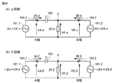
図20は、図3の故障点Fにおいて1線地絡故障が生じた場合のクラーク座標法による等価回路である。A端におけるα回路の電圧をVAαとし、α回路の電流をIAαとする。B端におけるα回路の電圧をVBαとし、α回路の電流をIBαとする。また、A端の零相電流をIA0とし、B端の零相電流IB0とする。A端の背後電源101_1のα回路における出力電圧をEAα=Eaとし、β回路における出力電圧をEAβ=−jEaとする。B端の背後電源101_2のα回路における出力電圧をEBα=Ebとし、β回路における出力電圧をEBβ=−jEbとする。
<1. Expression by simple equivalent circuit>
FIG. 20 is an equivalent circuit based on the Clark coordinate method when a one-line ground fault occurs at the fault point F in FIG. The voltage of the α circuit at the A end is VAα, and the current of the α circuit is IAα. The voltage of the α circuit at the B end is VBα, and the current of the α circuit is IBα. Further, the zero-phase current at the A end is IA0, and the zero-phase current at the B end is IB0. The output voltage in the α circuit of the rear power supply 101_1 at the A terminal is EAα=Ea, and the output voltage in the β circuit is EAβ=−jEa. The output voltage in the α circuit of the rear power supply 101_2 at the B end is EBα=Eb, and the output voltage in the β circuit is EBβ=−jEb.
図20に示すように、1線地絡故障の場合のクラーク座標法による等価回路は、故障点Fにおいてα回路と零相回路とが直列に接続された構成を有する。 As shown in FIG. 20, the equivalent circuit based on the Clark coordinate method in the case of a one-line ground fault has a configuration in which an α circuit and a zero-phase circuit are connected in series at a fault point F.
図21は、図3の故障点Fにおいて2線地絡故障が生じた場合のクラーク座標による等価回路である。A端におけるβ回路の電圧をVAβとし、β回路の電流をIAβとする。B端におけるβ回路の電圧をVBβとし、β回路の電流をIBβとする。 FIG. 21 is an equivalent circuit based on Clark coordinates when a two-wire ground fault occurs at the fault point F in FIG. The voltage of the β circuit at the A terminal is VAβ, and the current of the β circuit is IAβ. The voltage of the β circuit at the B end is VBβ, and the current of the β circuit is IBβ.
図21に示すように、2線地絡故障の場合のクラーク座標法による等価回路は、故障点Fにおいてα回路と零相回路が並列に接続されるともに、故障点Fにおいてβ回路が短絡された構成を有する。 As shown in FIG. 21, in the equivalent circuit based on the Clark coordinate method in the case of the two-wire ground fault, the α circuit and the zero-phase circuit are connected in parallel at the fault point F, and the β circuit is short-circuited at the fault point F. It has a different configuration.
図22は、図3の故障点Fにおいて2線短絡故障が生じた場合のクラーク座標による等価回路である。図22に示すように、2線短絡故障の場合のクラーク座標法による等価回路は、故障点Fにおいてβ回路が短絡された構成を有する。 22 is an equivalent circuit based on Clark coordinates when a two-wire short-circuit fault occurs at fault point F in FIG. As shown in FIG. 22, the equivalent circuit based on the Clark coordinate method in the case of a two-wire short-circuit fault has a configuration in which the β circuit is short-circuited at the fault point F.
図23は、図3の故障点Fにおいて3相故障が生じた場合のクラーク座標による等価回路である。図23に示すように、3相故障の場合のクラーク座標による等価回路は、故障点Fにおいてα回路が短絡されるとともに、故障点Fにおいてβ回路が短絡された構成を有する。 FIG. 23 is an equivalent circuit based on Clark coordinates when a three-phase failure occurs at the failure point F in FIG. As shown in FIG. 23, the Clarke coordinate equivalent circuit in the case of a three-phase fault has a configuration in which the α circuit is short-circuited at the fault point F and the β circuit is short-circuited at the fault point F.
図24は、図3の故障点Fにおいて故障が生じた場合のクラーク座標による簡易等価回路である。図24(A)はα回路による簡易等価回路を示し、故障点FにインピーダンスZFαが付加された構成を示している。故障点Fの電圧をVFαとする。図24(A)の簡易等価回路は、1線地絡故障および3相故障の場合に適用できる。 FIG. 24 is a simple equivalent circuit based on Clark coordinates when a failure occurs at the failure point F in FIG. FIG. 24A shows a simple equivalent circuit of the α circuit, and shows a configuration in which the impedance ZFα is added to the fault point F. The voltage at the failure point F is VFα. The simple equivalent circuit of FIG. 24A can be applied to the case of a one-line ground fault and a three-phase fault.
図24(B)はβ回路による簡易等価回路を示し、故障点FにインピーダンスZFβが付加された構成を示している。故障点Fの電圧をVFβとする。図24(B)の簡易等価回路は、2線地絡故障、2線短絡故障、3相故障の場合に適用できる。このように、クラーク変換の場合には、故障種類に応じて適用すべき簡易等価回路が異なる。 FIG. 24B shows a simple equivalent circuit of the β circuit, which shows a configuration in which the impedance ZFβ is added to the fault point F. The voltage at the fault point F is VFβ. The simple equivalent circuit of FIG. 24(B) can be applied to the case of a 2-wire ground fault, a 2-wire short-circuit fault, and a 3-phase fault. As described above, in the case of Clark conversion, the simple equivalent circuit to be applied differs depending on the type of failure.
<2.クラーク変換の変換式>
図25は、クラーク変換による変換式を表形式でまとめた図である。故障種類は、1線短絡故障、2線短絡故障、2線地絡故障、および3相故障の区別がある。
<2. Conversion formula of Clark conversion>
FIG. 25 is a diagram in which conversion formulas by the Clark conversion are summarized in a table format. The failure types are classified into a 1-line short-circuit fault, a 2-line short-circuit fault, a 2-line ground fault, and a 3-phase fault.
図25を参照して、1線地絡故障の場合は、α回路による簡易等価回路が用いられる。ただし、クラーク変換式が故障相に応じて異なる点に注意する必要がある。 With reference to FIG. 25, in the case of a one-line ground fault, a simple equivalent circuit using an α circuit is used. However, it should be noted that the Clark transform formula differs depending on the failure phase.
2線地絡故障または2線短絡故障の場合には、β回路による簡易等価回路が用いられる。ただし、クラーク変換式が故障相に応じて異なる点に注意する必要がある。 In the case of a two-wire ground fault or a two-wire short-circuit fault, a simple equivalent circuit using a β circuit is used. However, it should be noted that the Clark transform formula differs depending on the failure phase.
3相故障の場合には、図25では、β回路でbc相故障の場合の変換式が示されている。ただし、この場合は、他の相の変換式を用いてもよいし、α回路の変換式を用いることもできる。 In the case of a three-phase failure, FIG. 25 shows the conversion formula in the case of the bc phase failure in the β circuit. However, in this case, a conversion formula of another phase may be used, or a conversion formula of the α circuit may be used.
図25に示す変換式に従って送電線102の各端子の電圧および電流の座標変換が行われる。その後の故障点標定を行う手順については実施の形態1の場合とほぼ同様である。以下、図26および図27を参照して説明する。
Coordinate conversion of the voltage and current of each terminal of the
[故障点標定の具体的手順]
図26は、実施の形態3の故障点標定装置の機能ブロック図である。図27は、実施の形態3の故障点標定手順を示すフローチャートである。
[Specific procedure for fault location]
FIG. 26 is a functional block diagram of the fault point locating device according to the third embodiment. FIG. 27 is a flowchart showing a fault point locating procedure according to the third embodiment.
図26に示す故障点標定装置106の構成は、図12の故障点標定装置106の場合とほぼ同じである。ただし、図26の座標変換部123Aは、送電線102の各端子の電圧および電流の時系列データを、送電線故障検出部122から出力された故障相に応じて、α回路の電圧および電流の時系列データもしくはβ回路の電圧および電流の時系列データに変換する。なお、送電線故障検出部122が電流差動方式によって故障検出する場合には、故障相の特定は容易である。
The configuration of the fault
図26および図27を参照して、図27のステップS100からステップS104までは、図13および図14で説明した場合と同様であるので説明を繰り返さない。 26 and 27, steps S100 to S104 of FIG. 27 are similar to those described with reference to FIGS. 13 and 14, and therefore description thereof will not be repeated.
次のステップS105Aにおいて、第2の記憶領域RAM2は、電流または電圧の急変検出時刻の前後の予め定める期間(すなわち、図15のT1期間)におけるA端およびB端の電流および電圧時系列データを保存する。第2の記憶領域RAM2は、さらに、故障相の情報も保存する。 In the next step S105A, the second storage area RAM2 stores the current and voltage time series data of the A terminal and the B terminal in a predetermined period (that is, T1 period in FIG. 15) before and after the current or voltage sudden change detection time. save. The second storage area RAM2 also stores information on the failure phase.
次のステップS106Aにおいて、座標変換部123Aは、故障相の情報に基づいて、α回路およびβ回路のうちいずれを適用すべきかを決定するとともに、クラーク変換式を決定する。
In the next step S106A, the coordinate
図28は、図26の座標変換部123Aのより詳細な構成を示す機能ブロック図である。図28には、送電線故障検出部122の構成も示されている。
FIG. 28 is a functional block diagram showing a more detailed configuration of the coordinate
図28を参照して、送電線故障検出部122は、a相故障検出部130と、b相故障検出部131と、c相故障検出部132とを含む。a相故障検出部130は、電流差動方式によってa相送電線の保護区間における故障の有無を判定し、判定結果を座標変換部123Aに出力する。b相故障検出部131は、電流差動方式によってb相送電線の保護区間における故障の有無を判定すし、判定結果を座標変換部123Aに出力する。c相故障検出部132は、電流差動方式によってc相送電線の保護区間における故障の有無を判定し、判定結果を座標変換部123Aに出力する。
Referring to FIG. 28, the transmission line
座標変換部123Aは、a相故障検出部130、b相故障検出部131、c相故障検出部132の各出力に基づいて故障相を特定する論理演算部133〜139と、電圧電流の座標変換を行う演算部140〜145とを含む。
The coordinate
論理演算部133は、3相故障が生じているか否かを判定する。論理演算部134は、a相1線故障であるか否かを判定する。論理演算部135は、bc相の2線故障であるか否かを判定する。論理演算部136は、b相1線故障であるか否かを判定する。論理演算部137は、ca相の2線故障であるか否かを判定する。論理演算部138は、c相1線故障であるか否かを判定する。論理演算部139は、ab相の2線故障であるか否かを判定する。
The
演算部140〜145は、論理演算部133〜139の演算結果にそれぞれ基づいて、図25の表で示した変換式に従って送電線102の両端の電圧および電流の座標変換を行う。すなわち、1線故障の場合は、検出された故障相に対応する演算部は、故障相に応じた変換式を用いて、A端のα電圧VAαおよびα電流IAαとB端のα電圧VBαおよびα電流IBαとを算出する。2線故障の場合は、検出された故障相に対応する演算部は、故障相に応じた変換式を用いて、A端のβ電圧VAβおよびβ電流IAβとB端のβ電圧VBβおよびβ電流IBβとを算出する。3線故障の場合は、演算部133は、たとえば、β回路のbc相故障の場合と同じ式を用いて、A端のβ電圧VAβおよびβ電流IAβとB端のβ電圧VBβおよびβ電流IBβとを算出する(図27のステップS106A)。
The
図27の次のステップS107Aにおいて、故障区間判定部124は、ステップS106Aで算出したA端のα電圧VAαおよびα電流IAα(または、A端のβ電圧VAβおよびβ電流IAβ)を用いて、A端から見たインピーダンスVAα/IAα(または、インピーダンスVAβ/IAβ)の位相角φAを算出する。さらに、故障区間判定部124は、ステップS106Aで算出したB端のα電圧VBαおよびα電流IBα(または、B端のβ電圧VBβおよびβ電流IBβ)を用いて、B端から見たインピーダンスVBα/IBα(または、インピーダンスVBβ/IBβ)の位相角φBを算出する。
In the next step S107A of FIG. 27, the failure
次のステップS108において、故障区間判定部124は、位相角φAおよびφBの大小を判定する。故障区間判定部124は、φA<φBの場合には、故障点FはB端と直列コンデンサ103との間にあると判定する(ステップS109)。この場合、端子電圧補償部125は、前述の(5)式および(6)式に従ってA端のα電圧VAα(またはβ電圧VAβ)を補償した補償電圧VAα’(またはVAβ’)を算出し、故障点判定部126は、前述の(11)式の未知数Xを求める。ただし、前述の(5)式、(6)式、および(11)式において正相電圧はα電圧(またはβ電圧)に変更され、正相電流はα電流(またはβ電流)に変更される。
In the next step S108, the failure
実施の形態2で説明した保護回路付きの直列コンデンサ103の場合には、前述の(26)式を変更する必要がある。具体的に、a相地絡故障の場合には、保護回路付き直列コンデンサ103に生じる電圧VCは、
VC=[2*(Xva+Rva)*Ia−(Xvb+Rvb)*Ib−(Xvc+Rvc)*Ic]/3 …(27)
となる。bc相の短絡(地絡)故障および3相故障の場合は、保護回路付き直列コンデンサ103に生じる電圧VCは、Ib=−Icであるので、
VC=[(Xvb+Rvb)*Ib−(Xvc+Rvc)*Ic]/√3
=(2/√3)*(Xvb+Rvb)*Ib …(28)
となる。他相の故障の場合も上記と同様に電圧VCを計算できる。
In the case of the
VC=[2*(Xva+Rva)*Ia-(Xvb+Rvb)*Ib-(Xvc+Rvc)*Ic]/3 (27)
Becomes In the case of a short circuit (ground fault) fault and a three-phase fault of the bc phase, the voltage VC generated in the
VC=[(Xvb+Rvb)*Ib-(Xvc+Rvc)*Ic]/√3
=(2/√3)*(Xvb+Rvb)*Ib …(28)
Becomes In the case of a failure in another phase, the voltage VC can be calculated in the same manner as above.
その後の計算は実施の形態1の場合と同様に行われる。以下、簡単に説明すると、α回路(またはβ回路)のコンデンサ補償後のA端電圧VAα(β)’は、
VAα(β)’=VAα(β)+VC …(29)
となる。したがって、コンデンサ補償後のA端電圧VAα(β)’とA端電流とを用いて計算した故障点Fにおける電圧VFα(β)は、
VFα(β)=VAα(β)’−X*Z*IAα(β) …(30)
で与えられる。
Subsequent calculations are performed in the same manner as in the first embodiment. Briefly described below, the A terminal voltage VAα(β)′ after the capacitor compensation of the α circuit (or β circuit) is
VAα(β)'=VAα(β)+VC (29)
Becomes Therefore, the voltage VFα(β) at the failure point F calculated using the A-terminal voltage VAα(β)′ after the capacitor compensation and the A-terminal current is
VFα(β)=VAα(β)′−X*Z*IAα(β) (30)
Given in.
同様に、B端電圧VBα(β)とB端電流VBα(β)とを用いて計算した故障点Fにおける電圧VFα(β)は、
VFα(β)=VBα(β)−(1−X)*Z*IBα(β) …(31)
で与えられる。
Similarly, the voltage VFα(β) at the fault point F calculated using the B-terminal voltage VBα(β) and the B-terminal current VBα(β) is
VFα(β)=VBα(β)-(1-X)*Z*IBα(β) (31)
Given in.
A端の電圧および電流とB端の電圧および電流の完全な同時刻性を不要とするために、上式(30)および(31)の振幅値を演算し、故障点Fの電圧VFα(β)の振幅値VFα(β)ampの演算結果が互いに等しいとする。これによって、
(VAα(β)’−X*Z*IAα(β))amp
=(VBα(β)−(1−X)*Z*IBα(β))amp …(32)
が成立する。上式(32)において、未知数X以外は全て既知であるので、Xを算出できる。算出したXに送電線102の実際の亘長を乗算することによって、A端から故障点Fまでの距離を標定できる。
In order to eliminate the need for perfect simultaneousness of the voltage and current at the A terminal and the voltage and current at the B terminal, the amplitude values of the above equations (30) and (31) are calculated and the voltage VFα(β at the failure point F is calculated. ), the calculation results of the amplitude value VFα(β)amp are equal to each other. by this,
(VAα(β)′-X*Z*IAα(β))amp
=(VBα(β)-(1-X)*Z*IBα(β))amp (32)
Is established. In the above equation (32), all the values other than the unknown number X are known, so X can be calculated. By multiplying the calculated X by the actual length of the
一方、故障区間判定部124は、φA>φBの場合には、故障点FはA端の直列コンデンサ103との間にあると判定する(ステップS111)。この場合、端子電圧補償部125は、前述の(12)式および(13)式に従ってB端のα電圧VBα(またはβ電圧VBβ)を補償した補償電圧VBα’(またはVBβ’)を算出し、故障点判定部126は、前述の(18)式の未知数Xを求める。ただし、前述の(12)式、(13)式、および(18)式において正相電圧はα電圧(またはβ電圧)に変更され、正相電流はα電流(またはβ電流)に変更される。保護回路付きの直列コンデンサ103の場合には、直列コンデンサ103に生じる電圧VCが、前述の(27)式または(28)式に置き替えられる。算出したXに送電線102の実際の亘長を乗算することによって、A端から故障点Fまでの距離が標定できる。
On the other hand, when φA>φB, the failure
故障区間判定部124は、φA=φBの場合には、故障点Fは直列コンデンサ103の配置位置であると判定して(ステップS113)、処理を終了する。もしくは、φA=φBの場合には、判定不可として(11)式および(18)式の双方で未知数Xを求めることによって、A端から故障点Fまでの距離とB端から故障点Fまでの距離とを参考値として表示するようにしてもよい。
When φA=φB, the failure
[効果]
このようにクラーク座標法を利用する場合には、対称座標法と異なり、120°および240°の移相演算が不要である。このため、演算に必要なデータの検出期間(図15のT1期間)を短くできる。特に、保護回路付の直列コンデンサを用いる場合には、電流に応じて直列コンデンサの電圧が変化することを考慮する必要があるが、演算に必要なデータの検出期間を短くすることによって、演算誤差を減らすことができる。
[effect]
In this way, when the Clark coordinate method is used, unlike the symmetrical coordinate method, 120° and 240° phase shift calculations are unnecessary. Therefore, the detection period of data required for calculation (T1 period in FIG. 15) can be shortened. In particular, when using a series capacitor with a protection circuit, it is necessary to consider that the voltage of the series capacitor changes according to the current, but by shortening the detection period of the data required for calculation, the calculation error Can be reduced.
さらに、対称座標法を用いる実施の形態1の場合には、系統周波数が定格周波数からずれた場合に、電気角60°前のデータを用いて移相演算を行うと移相演算に誤差が生じる。これに対して、クラーク変換では現時刻の最新データしか使用しないので、座標変換による誤差を考慮する必要がないというメリットがある。
Further, in the case of the first embodiment using the symmetric coordinate method, when the system frequency deviates from the rated frequency, if the phase shift calculation is performed using the
[変形例]
実施の形態1〜3の故障点標定装置は、電流差動リレーのように送電線の両端の電流および電圧に基づいて送電線保護を行う送電線保護リレー装置に内蔵することができる。
[Modification]
The failure point locating devices of the first to third embodiments can be incorporated in a power transmission line protection relay device that protects the power transmission line based on the current and voltage at both ends of the power transmission line like a current differential relay.
今回開示された実施の形態はすべての点で例示であって制限的なものでないと考えられるべきである。この発明の範囲は上記した説明ではなくて請求の範囲によって示され、請求の範囲と均等の意味および範囲内でのすべての変更が含まれることが意図される。 The embodiments disclosed this time are to be considered as illustrative in all points and not restrictive. The scope of the present invention is shown not by the above description but by the scope of the claims, and is intended to include meanings equivalent to the scope of the claims and all modifications within the scope.
101 背後電源、102 送電線、103 直列コンデンサ、106,111 故障点標定装置、107 伝送路、108 通信装置、120 電圧データ入出力部、121 同期処理部、122 送電線故障検出部、123,123A 座標変換部、124 故障区間判定部、125 端子電圧補償部、126 故障点判定部、201 入力変換部、211 A/D変換部、221 演算処理部、222 CPU、231 I/O部、F 故障点。 101 Rear Power Supply, 102 Power Transmission Line, 103 Series Capacitor, 106, 111 Fault Locator, 107 Transmission Line, 108 Communication Device, 120 Voltage Data Input/Output Unit, 121 Synchronization Processing Unit, 122 Transmission Line Fault Detection Unit, 123, 123A Coordinate conversion unit, 124 failure section determination unit, 125 terminal voltage compensation unit, 126 failure point determination unit, 201 input conversion unit, 211 A/D conversion unit, 221 arithmetic processing unit, 222 CPU, 231 I/O unit, F failure point.
Claims (7)
前記送電線の各端子の3相電流および3相電圧の時系列データを正相電流および正相電圧の時系列データに変換する座標変換部と、
前記送電線の各端子について、前記直列コンデンサとの間に故障点が存在しない第1端子であるか、前記直列コンデンサとの間に前記故障点が存在する第2端子であるかを判定する故障区間判定部と、
前記直列コンデンサの有するインピーダンスによって生じる電圧を加算することによって前記第1端子の正相電圧を補償する端子電圧補償部と、
前記第1端子の正相電流と補償後の正相電圧とに基づく前記故障点の正相電圧の振幅と、前記第2端子の正相電流および正相電圧に基づく前記故障点の正相電圧の振幅とが等しいとして、故障点の位置を判定する故障点判定部とを備える、故障点標定装置。 A fault locator for a transmission line having a series capacitor on the line,
A coordinate conversion unit that converts time-series data of three-phase current and three-phase voltage of each terminal of the power transmission line into time-series data of positive-phase current and positive-phase voltage;
A failure that determines, for each terminal of the power transmission line, whether the terminal is the first terminal having no failure point with the series capacitor or the second terminal having the failure point with the series capacitor. A section determination unit,
A terminal voltage compensator for compensating the positive phase voltage of the first terminal by adding the voltage generated by the impedance of the series capacitor;
The amplitude of the positive phase voltage at the fault point based on the positive phase current at the first terminal and the compensated positive phase voltage, and the positive phase voltage at the fault point based on the positive phase current and the positive phase voltage at the second terminal. A fault point locating device that determines the position of the fault point assuming that the amplitudes of the fault points are equal.
前記送電線の一方の端子の正相電圧および正相電流から算出したインピーダンスの位相角と、前記送電線の他方の端子の正相電圧および正相電流から算出したインピーダンスの位相角とを比較し、
前記算出した位相角が小さいほうの端子を前記第1端子とし、前記算出した位相角が大きいほうの端子を前記第2端子とするように構成される、請求項1に記載の故障点標定装置。 The failure section determination unit,
The impedance phase angle calculated from the positive phase voltage and the positive phase current of one terminal of the transmission line is compared with the impedance phase angle calculated from the positive phase voltage and the positive phase current of the other terminal of the transmission line. ,
The fault location device according to claim 1, wherein the terminal having the smaller calculated phase angle is the first terminal and the terminal having the larger calculated phase angle is the second terminal. ..
前記端子電圧補償部は、前記第1端子の各相の電流と前記直列コンデンサのインピーダンス特性とに基づいて、前記第1端子の正相電圧に加算すべき電圧を算出する、請求項1または2に記載の故障点標定装置。 By including a protection circuit in the series capacitor, the series capacitor provided in each phase of the transmission line has a characteristic that impedance changes according to the current flowing through itself,
3. The terminal voltage compensator calculates a voltage to be added to the positive phase voltage of the first terminal based on the current of each phase of the first terminal and the impedance characteristic of the series capacitor. The fault location device described in.
前記送電線が1線故障の場合に前記送電線の各端子の3相電流および3相電圧の時系列データをα回路の電流および電圧の時系列データに座標変換し、前記送電線が2線故障の場合に前記送電線の各端子の3相電流および3相電圧の時系列データをβ回路の電流および電圧の時系列データに座標変換し、前記送電線が3相故障の場合に前記送電線の各端子の3相電流および3相電圧の時系列データをα回路およびβ回路のうちの一方の電流および電圧の時系列データに座標変換する座標変換部と、
前記送電線の各端子について、前記直列コンデンサとの間に故障点が存在しない第1端子であるか、前記直列コンデンサとの間に前記故障点が存在する第2端子であるかを判定する故障区間判定部と、
前記直列コンデンサの有するインピーダンスによって生じる電圧を加算することによって前記第1端子の前記座標変換後の電圧を補償する端子電圧補償部と、
前記第1端子の前記座標変換後の電流と前記補償された電圧とに基づく前記故障点の電圧の振幅と、前記第2端子の前記座標変換後の電流および電圧に基づく前記故障点の電圧の振幅とが等しいとして、前記故障点の位置を判定する故障点判定部とを備える、故障点標定装置。 A fault locator for a transmission line having a series capacitor on the line,
When the power transmission line has a one-line fault, the time-series data of the three-phase current and the three-phase voltage of each terminal of the power transmission line are coordinate-converted into the time-series data of the current and voltage of the α circuit, and the power transmission line has two lines. When there is a failure, the time-series data of the three-phase current and the three-phase voltage of each terminal of the power transmission line are converted into the time-series data of the current and voltage of the β circuit, and when the power transmission line has a three-phase failure, the transmission is performed. A coordinate conversion unit that converts the time-series data of the three-phase current and the three-phase voltage of each terminal of the electric wire into the time-series data of the current and voltage of one of the α circuit and the β circuit,
A failure that determines, for each terminal of the power transmission line, whether the terminal is the first terminal having no failure point with the series capacitor or the second terminal having the failure point with the series capacitor. A section determination unit,
A terminal voltage compensator for compensating the coordinate-converted voltage of the first terminal by adding the voltage generated by the impedance of the series capacitor;
Of the amplitude of the voltage at the fault point based on the coordinate-transformed current at the first terminal and the compensated voltage, and the voltage at the fault point based on the coordinate-transformed current and voltage at the second terminal. A fault point locating device, comprising: a fault point determination unit that determines the position of the fault point assuming that the amplitudes are equal.
前記送電線の一方の端子の前記座標変換後の電圧および電流から算出したインピーダンスの位相角と、前記送電線の他方の端子の前記座標変換後の電圧および電流から算出したインピーダンスの位相角とを比較し、
前記算出した位相角が小さいほうの端子を前記第1端子とし、前記算出した位相角が大きいほうの端子を前記第2端子とするように構成される、請求項4または5に記載の故障点標定装置。 The failure section determination unit,
The impedance phase angle calculated from the voltage and current after the coordinate conversion of one terminal of the power transmission line, and the phase angle of the impedance calculated from the voltage and current after the coordinate conversion of the other terminal of the power transmission line. Compare
The failure point according to claim 4 or 5, wherein the terminal having the smaller calculated phase angle is the first terminal and the terminal having the larger calculated phase angle is the second terminal. Orientation device.
前記端子電圧補償部は、前記第1端子の各相の電流と前記直列コンデンサのインピーダンス特性とに基づいて、前記第1端子の前記座標変換後の電圧に加算すべき電圧を算出する、請求項4〜6のいずれか1項に記載の故障点標定装置。
By including a protection circuit in the series capacitor, the series capacitor provided in each phase of the transmission line has a characteristic that impedance changes according to the current flowing through itself,
The terminal voltage compensator calculates a voltage to be added to the coordinate-converted voltage of the first terminal based on the current of each phase of the first terminal and the impedance characteristic of the series capacitor. The fault point locating device according to any one of 4 to 6.
Priority Applications (1)
| Application Number | Priority Date | Filing Date | Title |
|---|---|---|---|
| JP2017060880A JP6739384B2 (en) | 2017-03-27 | 2017-03-27 | Failure point locator |
Applications Claiming Priority (1)
| Application Number | Priority Date | Filing Date | Title |
|---|---|---|---|
| JP2017060880A JP6739384B2 (en) | 2017-03-27 | 2017-03-27 | Failure point locator |
Publications (2)
| Publication Number | Publication Date |
|---|---|
| JP2018163065A JP2018163065A (en) | 2018-10-18 |
| JP6739384B2 true JP6739384B2 (en) | 2020-08-12 |
Family
ID=63859809
Family Applications (1)
| Application Number | Title | Priority Date | Filing Date |
|---|---|---|---|
| JP2017060880A Active JP6739384B2 (en) | 2017-03-27 | 2017-03-27 | Failure point locator |
Country Status (1)
| Country | Link |
|---|---|
| JP (1) | JP6739384B2 (en) |
Families Citing this family (5)
| Publication number | Priority date | Publication date | Assignee | Title |
|---|---|---|---|---|
| KR102638967B1 (en) * | 2019-11-20 | 2024-02-22 | 한국전력공사 | Apparatus for imaging power data and method thereof |
| EP4196802A1 (en) * | 2020-08-11 | 2023-06-21 | Abb Schweiz Ag | Method of determining line fault of power system |
| CN113075499B (en) * | 2021-03-10 | 2022-01-07 | 华中科技大学 | Instantaneous value variation distance protection method and system based on coordinate transformation |
| CN114019283A (en) * | 2021-11-04 | 2022-02-08 | 杭州老板电器股份有限公司 | Capacitance fault detection method and device and range hood |
| CN114236305B (en) * | 2021-11-09 | 2023-08-15 | 中国电建集团华东勘测设计研究院有限公司 | Single-core cable on-line fault positioning device and method |
-
2017
- 2017-03-27 JP JP2017060880A patent/JP6739384B2/en active Active
Also Published As
| Publication number | Publication date |
|---|---|
| JP2018163065A (en) | 2018-10-18 |
Similar Documents
| Publication | Publication Date | Title |
|---|---|---|
| JP6739384B2 (en) | Failure point locator | |
| Ghorbani et al. | Negative-sequence network based fault location scheme for double-circuit multi-terminal transmission lines | |
| RU2416851C2 (en) | Method and relay of adaptive remote protection for power transmission lines | |
| US11307264B2 (en) | Phase selection for traveling wave fault detection systems | |
| US6584417B1 (en) | Method and directional element for fault direction determination in a capacitance-compensated line | |
| US8183871B2 (en) | Method and device for fault location in a two-terminal transmission or distribution power line | |
| US9476930B2 (en) | Locating multi-phase faults in ungrounded power distribution systems | |
| US10393810B2 (en) | Method for identifying the fault by current differential protection and device thereof | |
| Khan et al. | Transmission line fault detection and identification in an interconnected power network using phasor measurement units | |
| JP6271114B1 (en) | Current differential relay and sampling synchronization method | |
| EP3312621A1 (en) | Leak current detecting device | |
| Adharapurapu et al. | A novel algorithm for improving the differential protection of power transmission system | |
| KR102057201B1 (en) | Out of order discrimination apparatus and protective relay apparatus | |
| KR101986036B1 (en) | Protection relay device | |
| US20240044965A1 (en) | Parameter independent traveling wave-based fault location using unsynchronized measurements | |
| JP6804358B2 (en) | Single point of failure indicator | |
| Sharma et al. | Voltage-assisted sequence current-based pilot relaying for lines with/without TCSC | |
| JP2013090445A (en) | Power system protection system | |
| Voloh et al. | Fault locator based on line current differential relays synchronized measurements | |
| JP4921246B2 (en) | Ground fault distance relay | |
| CN109997287B (en) | Method and control system for fault direction detection | |
| Jiang et al. | A composite index to adaptively perform fault detection, classification, and direction discrimination for transmission lines | |
| Rosolowski et al. | Fault location algorithm for use with current differential protective relays of double-circuit line | |
| Kazmi et al. | Comparison of high-speed transient-based pilot directional protection algorithms for distribution grids | |
| Holbach et al. | Loop selective direction measurement for distance protection |
Legal Events
| Date | Code | Title | Description |
|---|---|---|---|
| A621 | Written request for application examination |
Free format text: JAPANESE INTERMEDIATE CODE: A621 Effective date: 20190723 |
|
| A977 | Report on retrieval |
Free format text: JAPANESE INTERMEDIATE CODE: A971007 Effective date: 20200422 |
|
| TRDD | Decision of grant or rejection written | ||
| A01 | Written decision to grant a patent or to grant a registration (utility model) |
Free format text: JAPANESE INTERMEDIATE CODE: A01 Effective date: 20200623 |
|
| A61 | First payment of annual fees (during grant procedure) |
Free format text: JAPANESE INTERMEDIATE CODE: A61 Effective date: 20200721 |
|
| R150 | Certificate of patent or registration of utility model |
Ref document number: 6739384 Country of ref document: JP Free format text: JAPANESE INTERMEDIATE CODE: R150 |
|
| R250 | Receipt of annual fees |
Free format text: JAPANESE INTERMEDIATE CODE: R250 |